EP3330484A1 - Method and device for controlling the positioning of at least one rotor disc about a tie-rod of a gas turbine rotor - Google Patents
Method and device for controlling the positioning of at least one rotor disc about a tie-rod of a gas turbine rotor Download PDFInfo
- Publication number
- EP3330484A1 EP3330484A1 EP17205557.6A EP17205557A EP3330484A1 EP 3330484 A1 EP3330484 A1 EP 3330484A1 EP 17205557 A EP17205557 A EP 17205557A EP 3330484 A1 EP3330484 A1 EP 3330484A1
- Authority
- EP
- European Patent Office
- Prior art keywords
- rotor disc
- rotor
- respect
- detecting
- parameter correlated
- Prior art date
- Legal status (The legal status is an assumption and is not a legal conclusion. Google has not performed a legal analysis and makes no representation as to the accuracy of the status listed.)
- Granted
Links
Images




Classifications
-
- F—MECHANICAL ENGINEERING; LIGHTING; HEATING; WEAPONS; BLASTING
- F01—MACHINES OR ENGINES IN GENERAL; ENGINE PLANTS IN GENERAL; STEAM ENGINES
- F01D—NON-POSITIVE DISPLACEMENT MACHINES OR ENGINES, e.g. STEAM TURBINES
- F01D25/00—Component parts, details, or accessories, not provided for in, or of interest apart from, other groups
- F01D25/28—Supporting or mounting arrangements, e.g. for turbine casing
- F01D25/285—Temporary support structures, e.g. for testing, assembling, installing, repairing; Assembly methods using such structures
-
- F—MECHANICAL ENGINEERING; LIGHTING; HEATING; WEAPONS; BLASTING
- F01—MACHINES OR ENGINES IN GENERAL; ENGINE PLANTS IN GENERAL; STEAM ENGINES
- F01D—NON-POSITIVE DISPLACEMENT MACHINES OR ENGINES, e.g. STEAM TURBINES
- F01D5/00—Blades; Blade-carrying members; Heating, heat-insulating, cooling or antivibration means on the blades or the members
- F01D5/02—Blade-carrying members, e.g. rotors
- F01D5/06—Rotors for more than one axial stage, e.g. of drum or multiple disc type; Details thereof, e.g. shafts, shaft connections
- F01D5/066—Connecting means for joining rotor-discs or rotor-elements together, e.g. by a central bolt, by clamps
-
- F—MECHANICAL ENGINEERING; LIGHTING; HEATING; WEAPONS; BLASTING
- F01—MACHINES OR ENGINES IN GENERAL; ENGINE PLANTS IN GENERAL; STEAM ENGINES
- F01D—NON-POSITIVE DISPLACEMENT MACHINES OR ENGINES, e.g. STEAM TURBINES
- F01D5/00—Blades; Blade-carrying members; Heating, heat-insulating, cooling or antivibration means on the blades or the members
- F01D5/02—Blade-carrying members, e.g. rotors
- F01D5/027—Arrangements for balancing
-
- F—MECHANICAL ENGINEERING; LIGHTING; HEATING; WEAPONS; BLASTING
- F04—POSITIVE - DISPLACEMENT MACHINES FOR LIQUIDS; PUMPS FOR LIQUIDS OR ELASTIC FLUIDS
- F04D—NON-POSITIVE-DISPLACEMENT PUMPS
- F04D29/00—Details, component parts, or accessories
- F04D29/26—Rotors specially for elastic fluids
- F04D29/32—Rotors specially for elastic fluids for axial flow pumps
- F04D29/321—Rotors specially for elastic fluids for axial flow pumps for axial flow compressors
-
- F—MECHANICAL ENGINEERING; LIGHTING; HEATING; WEAPONS; BLASTING
- F04—POSITIVE - DISPLACEMENT MACHINES FOR LIQUIDS; PUMPS FOR LIQUIDS OR ELASTIC FLUIDS
- F04D—NON-POSITIVE-DISPLACEMENT PUMPS
- F04D29/00—Details, component parts, or accessories
- F04D29/60—Mounting; Assembling; Disassembling
- F04D29/64—Mounting; Assembling; Disassembling of axial pumps
- F04D29/644—Mounting; Assembling; Disassembling of axial pumps especially adapted for elastic fluid pumps
-
- F—MECHANICAL ENGINEERING; LIGHTING; HEATING; WEAPONS; BLASTING
- F05—INDEXING SCHEMES RELATING TO ENGINES OR PUMPS IN VARIOUS SUBCLASSES OF CLASSES F01-F04
- F05D—INDEXING SCHEME FOR ASPECTS RELATING TO NON-POSITIVE-DISPLACEMENT MACHINES OR ENGINES, GAS-TURBINES OR JET-PROPULSION PLANTS
- F05D2230/00—Manufacture
- F05D2230/50—Building or constructing in particular ways
-
- F—MECHANICAL ENGINEERING; LIGHTING; HEATING; WEAPONS; BLASTING
- F05—INDEXING SCHEMES RELATING TO ENGINES OR PUMPS IN VARIOUS SUBCLASSES OF CLASSES F01-F04
- F05D—INDEXING SCHEME FOR ASPECTS RELATING TO NON-POSITIVE-DISPLACEMENT MACHINES OR ENGINES, GAS-TURBINES OR JET-PROPULSION PLANTS
- F05D2230/00—Manufacture
- F05D2230/50—Building or constructing in particular ways
- F05D2230/51—Building or constructing in particular ways in a modular way, e.g. using several identical or complementary parts or features
-
- F—MECHANICAL ENGINEERING; LIGHTING; HEATING; WEAPONS; BLASTING
- F05—INDEXING SCHEMES RELATING TO ENGINES OR PUMPS IN VARIOUS SUBCLASSES OF CLASSES F01-F04
- F05D—INDEXING SCHEME FOR ASPECTS RELATING TO NON-POSITIVE-DISPLACEMENT MACHINES OR ENGINES, GAS-TURBINES OR JET-PROPULSION PLANTS
- F05D2230/00—Manufacture
- F05D2230/60—Assembly methods
- F05D2230/64—Assembly methods using positioning or alignment devices for aligning or centring, e.g. pins
- F05D2230/644—Assembly methods using positioning or alignment devices for aligning or centring, e.g. pins for adjusting the position or the alignment, e.g. wedges or eccenters
Definitions
- the invention relates to a method and a device for controlling the positioning of a rotor disc about a tie-rod of a gas turbine rotor.
- a gas turbine rotor of an industrial plant for the production of electrical energy usually comprises a plurality of bladed rotor discs, which are aligned along an axis and are coupled at the front.
- the front coupling between adjacent rotor discs is obtained by means of Hirth joints.
- each rotor disc is provided with two respective radial teeth annuli, the so-called Hirth teeth sets, one on each face.
- the annuli are coupled to annuli of adjacent discs so as to build the so-called Hirth joints.
- the rotors discs are provided with respective blade sets and are bound into packs by a central tie-rod, which engages respective central holes of the rotor discs.
- Each bladed disc defines a compressor or turbine rotor stage.
- Gas turbine rotors must be produced and assembled with utmost precision, so as to ensure a nearly perfect balancing. Given the masses and the high rotation speeds (the rotor usually rotates at 3000 rpm or 3600 rpm, depending on the standards of the different countries), even the smallest defects can cause dangerous vibrations exceeding the allowed limits, thus forcing the plant to be stopped in order to carry out corrective interventions aimed at bringing the vibrations back to the allowed limits.
- Assembling a rotor currently involves stacking the rotor discs about a central tie-rod arranged in a vertical position.
- the rotor discs automatically center themselves, thanks to the fact that the contact between the discs occurs through the Hirth toothing described above.
- Assembling the rotor usually requires stacking a large number of rotor discs (e.g. about twenty). Therefore, having a lack of homogeneity in just one of these discs (for example, due to the fact that the disc has non-parallel faces) is enough to obtain, at the end of the stacking step, an inclined stack, namely a stack where the center of the last disc is not vertically aligned with the one of the first disc.
- the compliance of the discs is usually controlled when the rotor is already clamped and possible corrective actions often require the rotor to be disassembled.
- the invention relates to a method for controlling the positioning of rotor discs about a tie-rod of a gas turbine rotor; the method comprising the step of detecting at least one parameter correlated to the position of the rotor disc with respect to one or more references.
- a further object is to provide a device for controlling the positioning of rotor discs about a tie-rod of a gas turbine rotor, which is precise, reliable and capable of easing the operations to be carried out in order to check the compliance of the discs, thus minimizing operators' manual activities and personal assessments.
- the invention relates to a device for controlling the positioning of at least one rotor disc about a tie-rod of a gas turbine rotor; the device comprising:
- reference number 1 indicates a gas turbine rotor of a plant for the production of electrical energy comprising a plurality of discs 2 aligned along an axis A and bound into packs by means of a central tie-rod 3.
- a first group of discs 2, provided with respective first rotor blades 5, defines a compressor section 1a of the rotor 1
- a second group of discs 2, provided with respective second rotor blades 6, defines a turbine section 1b of the rotor 1.
- the compressor section 1a and the turbine section 1b are separated from one another by a disc 2 without blades, which basically acts as a spacer element and is substantially shaped like a cylinder.
- an annular combustion chamber (not shown) of the gas turbine can be arranged around the spacer disc 2.
- each rotor disc 2 is provided with a central through hole 8 and with a peripheral edge 9 provided with a plurality of seats 10 properly shaped so as to be coupled to respective first rotor blades 5 or to respective second rotor blades 6.
- the central hole 8 will be engaged, in use, by the tie-rod 3 of the rotor 1.
- Each rotor disc 2 is further provided with a radial teeth annulus 12, commonly named as Hirth toothing, on each face 13a, 13b of the rotor disc 2 (in figure 3 you can only see the face 13a of the rotor disc, whereas the face 13b is partially shown in figures 1 and 2 ).
- the radial teeth annulus 12 is arranged along the respective face close to the peripheral edge 9 of the rotor disc 2.
- the radial teeth annuli 12 are positioned and shaped so as to be coupled to the annuli of the adjacent rotor discs 2 in order to build the so-called Hirth joint and to ensure a stable coupling of the rotor discs 2.
- Figure 2 shows a partially assembled rotor 1, in which the tie-rod 3 is arranged and supported in a vertical position.
- the tie rod 3 has an end portion, which is housed in a stacking pit (not shown for the sake of simplicity), which ensures a correct and stable vertical positioning of the tie-rod 3.
- the configuration shown in figure 2 can occur both during the assembling of the rotor 1 (when the rotor discs 2 are stacked on top of one another, so that the radial teeth annuli 12 of the adjacent rotor discs 2 can be coupled to one another in order to build the Hirth joints) and during the disassembling of the rotor 1 (when the rotor discs 2 are removed one by one).
- the method for controlling the positioning of at least one rotor disc 2 about a tie-rod 3 according to the invention is applied to a partially assembled rotor 1 like in the configuration of figure 2 .
- the method comprises detecting at least one parameter correlated to the position of at least one rotor disc 2 with respect to one or more references through a device 15 coupled to a free face 13a of the rotor disc 2 (in figure 2 , the device 15 is schematically represented liked a sectional disc, more details on the device 15 will be described hereinafter with reference to figure 4 ).
- free face we here and hereinafter mean a face of the rotor disc 2 that is not coupled to a further face of the adjacent rotor disc 2.
- the method according to the invention can be applied both during the assembling and during the disassembling of the rotor 1.
- the detection of the position of the disc 2 takes place before a further rotor disc 2 is stacked on the rotor disc 2 being controlled, whereas, during the disassembling, the detection of the position of the rotor disc 2 takes place before the rotor disc 2 being controlled is removed.
- the method according to the invention requires the device 15 to be coupled to one rotor disc 2 at a time.
- this does not imply that the positioning control must be carried out for each disc of the rotor 1.
- the device 15 comprises a support 16, a centering system 17 configured to center the support 16 on the rotor disc 2 being controlled, at least one detecting assembly 19 coupled to the support 16 and configured to detect at least one parameter correlated to the position of the rotor disc 2 with respect to one or more references, and a control device 20.
- the support 16 preferably is defined by a frame configured to support the centering system 17 and the detecting assembly 19.
- the support 16 is provided with a coupling device 18 configured so as to provide hooking points for the lifting of the support 16, for example by means of an overhead crane (not shown).
- the coupling device 18 comprises a plurality of eyelets 18a, which are arranged along the outer edge of the support 16 and can be coupled to the snap links of the overhead crane (not shown).
- the support 16 has an annular shape having dimensions that are compatible with the dimensions of the tie-rod 3 and of the rotor discs 2 making up the rotor 1.
- the support 16 is defined by an annular frame, which is sized so as to make sure that the tie-rod can be easily inserted into the support 16.
- the support 16 has a first annular face 21, which is designed to face, in use, the rotor disc 2 being controlled, and a second annular face 22, which is opposite the first annular face 21.
- the support 16 comprises a hooking device, which is designed to hook the rotor disc 2.
- the hooking device can be defined, for example, by three reverse vices arranged at 120° from another, which, by expanding, get locked on the radial teeth annulus 12 of the rotor disc 2 to be lifted.
- the centering system 17 comprises at least two portions of a Hirth toothing annulus 23 couplable to a respective portion of the radial teeth (Hirth) annulus 12 arranged on a free face 13a of one of the rotor discs 2 making up the rotor 1.
- Hirth toothing annulus 23 are coupled to the first annular face 21 so as to face, in use, the rotor disc 2 being controlled.
- the portions of Hirth toothing annulus 23 must be shaped so as to have a minimum radius that is equal to the inner radius of the radial teeth annulus 12 of the smallest rotor disc 2 and a maximum radius that is equal to the outer radius of the radial teeth annulus 12 of the largest rotor disc 2.
- the portions of Hirth toothing annulus 23 must have teeth that are oriented like the teeth of the radial teeth annulus 12, namely towards the center of the rotor discs 2, preserving all other parameters thereof (inclination of the walls of the teeth, number of teeth, etc.), so as to ensure a correct and stable coupling between the portions of Hirth toothing annulus 23 and the radial teeth annulus 12 of the rotor discs 2.
- the centering system 17 comprises three portions of Hirth toothing annulus 23 that are separate and arranged on a same plane, preferably at approximately 120° from one another.
- Hirth toothing annulus 23 The three portions of Hirth toothing annulus 23 are substantially identical.
- Hirth toothing annulus 23 substantially define a coupling face of the device 16, which is designed to be arranged in contact with the free face 13a of the rotor disc 2 being controlled.
- the portions of Hirth toothing annulus 23 are manufactured as one single piece together with the support 16.
- the support 16 is coupled to the rotor disc 2 being controlled in an integral manner and is centered on the rotor disc 2 being controlled.
- the portions of Hirth toothing annulus 23 project from the first annular face 21 of the support 16, so that the support 16 does not interfere with the radial teeth annulus 12 of the rotor discs 2 (see the section along plane VI-VI shown in figure 6 ).
- the detecting assembly 19 comprises a first device 27 configured to detect at least one parameter correlated to the inclination of the rotor disc 2 with respect to a horizontal plane and a second device 28 configured to detect at least one parameter correlated to the eccentricity of the rotor disc 2 with respect to the tie-rod 3 of the rotor 1 about which the rotor disc 2 is arranged.
- the first device 27 comprises a biaxial inclinometer, which is coupled to the support 16 and is capable of providing the measure of the inclination of the support 16 with respect to two orthogonal axes.
- the inclination measures of the first device 27 reflect the inclination of the rotor disc 2 to which the device 15 is coupled.
- the first device 27 is coupled to the second annular face 22 of the support 16.
- the second device 28 comprises at least three distance detectors 30, which are coupled to the support 16, are arranged in respective points belonging to a same circumference (represented with a broken line in figure 4 ) and are oriented towards the center of the circumference.
- the distance detectors 30 detect a distance along a radial direction with respect to center of the circumference and aim at a specific target: the tie-rod 3.
- the second device 28 comprises three distance detectors 30, which are arranged at 120° with respect to one another along the circumference and are configured to detect three radial distances R1, R2, R3.
- the distance detectors 30 are coupled to the second annular face 22 of the support 16.
- the distance detectors 30 preferably are contactless detectors, for example laser triangulation systems.
- the quantities R1, R2, R3 are detected with a very high precision (resolution up to a hundredth of a millimeter).
- the distance detectors 30 aim at the tie-rod 3 along a radial direction. By so doing, the distance detectors 30 detect three radial distance values R1, R2, R3 with respect to the tie-rod 3.
- the data detected by the first device 27 and by the second device 28 are sent to the control device 20, which is schematically shown in figure 5 .
- the control device 20 is configured to process the data detected by the detecting assembly 19 and supply an assessment of the positioning of the rotor disc 2.
- the control device 20 preferably comprises a storing module 101, in which all the inclination data detected by the first device 27 are stored in succession for the different rotor discs 2, a calculation module 102, which is configured to calculate the relative inclination of each rotor disc 2 with respect to the rotor disc 2 preceding it, and an inclination assessment module 103, which is configured to assess whether the absolute inclination value detected by the first detecting device 27 and the relative inclination value calculated by the calculation module 102 are within respective tolerance limits.
- the tolerance interval for the relative inclination of a single rotor disc is +/- 1/1000°.
- the tolerance interval for the absolute inclination is +/- 2/100°.
- the calculation module 102 calculates the relative inclination as difference between detected absolute inclinations of adjacent rotor discs 2.
- control system 20 signals a fault.
- control device 20 comprises a further module, which is configured to give indications on possible corrective actions to be carried out in the light of the relative and absolute inclination data stored in the storing module 101.
- control device 20 further comprises a comparing module 105, which is configured to compare the distance data detected by the second device 28 and to signal an eccentricity occurrence when the difference between the detected distances is greater than a threshold value.
- the threshold value is approximately equal to 0.1 mm.
- the data detected by the first device 27 and by the second device 28 are sent to the control device 20 by means of wi-fi communications.
- control device 20 is not coupled to the support 16 and is integrated in an external processor (e.g. a tablet) available to the operator who follows the assembling/disassembling of the rotor 1, as you can schematically see in the accompanying figures.
- an external processor e.g. a tablet
- the tablet can give the operator information on the correct positioning of the disc on the stack, respecting all tolerances, and, in any case, store the information.
- the device 15 is further provided with a pointer 35, which is coupled to the support 16 and is configured to generate a light beam along a given direction towards the outside of the support 16.
- the beam generated by so doing can be used to provide a reference of the angular position of the device 15.
- a reference element 36 extending along a vertical axis.
- the reference element can be defined by any fixed element close to the rotor 1, which can be used as a reference point.
- the pointer 35 allows the device 15 to be always arranged, with every detection, in the same angular position with respect to the tie-rod 3.
- the pointer 35 is configured so as to generate a substantially horizontal and radial beam when the device is coupled to the rotor disc 2 being controlled.
- the device 15 and the method for controlling the positioning of a rotor disc according to the invention allow the assembling of the rotor 1 to be improved and optimized, thus avoiding assembling an unbalanced rotor and avoiding, especially, the costs deriving from one or more corrective interventions to be carried out on an already assembled rotor.
- the device 15 and the method for controlling the positioning of a rotor disc according to the invention can also be applied to already assembled rotors that were assembled with the preceding assembling techniques.
- the device 15 and the method according to the invention can be applied during the disassembling of the rotor 1 disc by disc.
- the rotor discs 2 are removed one at a time and the device 15 is used to detect the position of each rotor disc 2 until the rotor disc (or the rotor discs) is (are) found that is (are) responsible for the unbalance of the rotor 1.
- the application of the device 15 during the disassembling of the rotor 1 is advantageous compared to currently known solutions, as it gives objective indications on the positioning of each rotor disc 2, without introducing operators' personal assessment elements.
- the identification of an unbalance does not always lead to the replacement of the rotor disc 2.
- the unbalance can simply be corrected by means of proper rotations of the rotor discs.
- the device 16 has a crucial role in establishing whether the corrective actions were effective and sufficient to compensate the unbalance.
Landscapes
- Engineering & Computer Science (AREA)
- Mechanical Engineering (AREA)
- General Engineering & Computer Science (AREA)
- Turbine Rotor Nozzle Sealing (AREA)
Abstract
Description
- The invention relates to a method and a device for controlling the positioning of a rotor disc about a tie-rod of a gas turbine rotor.
- A gas turbine rotor of an industrial plant for the production of electrical energy usually comprises a plurality of bladed rotor discs, which are aligned along an axis and are coupled at the front. The front coupling between adjacent rotor discs is obtained by means of Hirth joints.
- Therefore, each rotor disc is provided with two respective radial teeth annuli, the so-called Hirth teeth sets, one on each face. The annuli are coupled to annuli of adjacent discs so as to build the so-called Hirth joints.
- The rotors discs are provided with respective blade sets and are bound into packs by a central tie-rod, which engages respective central holes of the rotor discs.
- Each bladed disc defines a compressor or turbine rotor stage.
- Gas turbine rotors must be produced and assembled with utmost precision, so as to ensure a nearly perfect balancing. Given the masses and the high rotation speeds (the rotor usually rotates at 3000 rpm or 3600 rpm, depending on the standards of the different countries), even the smallest defects can cause dangerous vibrations exceeding the allowed limits, thus forcing the plant to be stopped in order to carry out corrective interventions aimed at bringing the vibrations back to the allowed limits.
- Assembling a rotor currently involves stacking the rotor discs about a central tie-rod arranged in a vertical position. The rotor discs automatically center themselves, thanks to the fact that the contact between the discs occurs through the Hirth toothing described above.
- Assembling the rotor usually requires stacking a large number of rotor discs (e.g. about twenty). Therefore, having a lack of homogeneity in just one of these discs (for example, due to the fact that the disc has non-parallel faces) is enough to obtain, at the end of the stacking step, an inclined stack, namely a stack where the center of the last disc is not vertically aligned with the one of the first disc.
- The compliance of the discs is usually controlled when the rotor is already clamped and possible corrective actions often require the rotor to be disassembled.
- Moreover, the tools and the methods currently available take a long time to assess and correct the stacking. There are checks that control the compliance of the discs before the stacking, but they do not ensure the detection of all non-compliances of the discs, as operators need to carry out manual activities and personal assessments. Therefore, the accuracy and the times needed for the checks and the corrections cannot be considered as satisfying.
- Hence, it is important to have a method for controlling the positioning of rotor discs about a tie-rod of a gas turbine rotor that is precise and reliable and avoids, or minimizes, the occurrence of balancing errors. By so doing, you can avoid, or minimize, assessment and correction operations to be carried on an already clamped rotor.
- In accordance with these objects, the invention relates to a method for controlling the positioning of rotor discs about a tie-rod of a gas turbine rotor; the method comprising the step of detecting at least one parameter correlated to the position of the rotor disc with respect to one or more references.
- A further object is to provide a device for controlling the positioning of rotor discs about a tie-rod of a gas turbine rotor, which is precise, reliable and capable of easing the operations to be carried out in order to check the compliance of the discs, thus minimizing operators' manual activities and personal assessments.
- In accordance with these objects, the invention relates to a device for controlling the positioning of at least one rotor disc about a tie-rod of a gas turbine rotor; the device comprising:
- a support;
- a centering system configured to center the support on a rotor disc of the rotor;
- at least one detecting assembly coupled to the support and configured to detect at least one parameter correlated to the position of the rotor disc with respect to one or more references.
- The invention will now be described with reference to the accompanying drawings, which show a non-limiting embodiment thereof, wherein:
-
figure 1 is a side view of a gas turbine rotor with a section along a vertical axial plane; -
figure 2 is a side view of the rotor offigure 1 partially assembled during a step of the method according to the invention; -
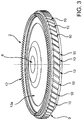
figure 3 is a perspective view of a detail of the rotor offigure 1 ; -
figure 4 is a plan view from the bottom of a device for assembling the rotor according to the invention; -
figure 5 is a plan view from the top of the device offigure 4 ; -
figure 6 is a section along plane VI-VI of the device offigure 4 ; -
figure 7 is a schematic block diagram of a detail of the device offigure 5 . - In
figure 1 ,reference number 1 indicates a gas turbine rotor of a plant for the production of electrical energy comprising a plurality ofdiscs 2 aligned along an axis A and bound into packs by means of a central tie-rod 3. A first group ofdiscs 2, provided with respectivefirst rotor blades 5, defines acompressor section 1a of therotor 1, whereas a second group ofdiscs 2, provided with respectivesecond rotor blades 6, defines aturbine section 1b of therotor 1. Thecompressor section 1a and theturbine section 1b are separated from one another by adisc 2 without blades, which basically acts as a spacer element and is substantially shaped like a cylinder. In use, an annular combustion chamber (not shown) of the gas turbine can be arranged around thespacer disc 2. - With reference to
figure 3 , eachrotor disc 2 is provided with a central throughhole 8 and with aperipheral edge 9 provided with a plurality ofseats 10 properly shaped so as to be coupled to respectivefirst rotor blades 5 or to respectivesecond rotor blades 6. - The
central hole 8 will be engaged, in use, by the tie-rod 3 of therotor 1. - Each
rotor disc 2 is further provided with aradial teeth annulus 12, commonly named as Hirth toothing, on eachface figure 3 you can only see theface 13a of the rotor disc, whereas theface 13b is partially shown infigures 1 and2 ). - Preferably, the
radial teeth annulus 12 is arranged along the respective face close to theperipheral edge 9 of therotor disc 2. - The
radial teeth annuli 12 are positioned and shaped so as to be coupled to the annuli of theadjacent rotor discs 2 in order to build the so-called Hirth joint and to ensure a stable coupling of therotor discs 2. -
Figure 2 shows a partially assembledrotor 1, in which the tie-rod 3 is arranged and supported in a vertical position. Preferably, thetie rod 3 has an end portion, which is housed in a stacking pit (not shown for the sake of simplicity), which ensures a correct and stable vertical positioning of the tie-rod 3. - The configuration shown in
figure 2 can occur both during the assembling of the rotor 1 (when therotor discs 2 are stacked on top of one another, so that the radial teeth annuli 12 of theadjacent rotor discs 2 can be coupled to one another in order to build the Hirth joints) and during the disassembling of the rotor 1 (when therotor discs 2 are removed one by one). - The method for controlling the positioning of at least one
rotor disc 2 about a tie-rod 3 according to the invention is applied to a partially assembledrotor 1 like in the configuration offigure 2 . - Indeed, the method comprises detecting at least one parameter correlated to the position of at least one
rotor disc 2 with respect to one or more references through adevice 15 coupled to afree face 13a of the rotor disc 2 (infigure 2 , thedevice 15 is schematically represented liked a sectional disc, more details on thedevice 15 will be described hereinafter with reference tofigure 4 ). - By free face we here and hereinafter mean a face of the
rotor disc 2 that is not coupled to a further face of theadjacent rotor disc 2. - Therefore, the method according to the invention can be applied both during the assembling and during the disassembling of the
rotor 1. - During the assembling, the detection of the position of the
disc 2 takes place before afurther rotor disc 2 is stacked on therotor disc 2 being controlled, whereas, during the disassembling, the detection of the position of therotor disc 2 takes place before therotor disc 2 being controlled is removed. - As a consequence, the method according to the invention requires the
device 15 to be coupled to onerotor disc 2 at a time. However, this does not imply that the positioning control must be carried out for each disc of therotor 1. It is also possible to control the positioning of groups of coupledrotor discs 2 by means of the detection of the position of therotor disc 2 belonging to the group that has a free face. - With reference to
figures 4 and 5 , thedevice 15 comprises asupport 16, acentering system 17 configured to center thesupport 16 on therotor disc 2 being controlled, at least onedetecting assembly 19 coupled to thesupport 16 and configured to detect at least one parameter correlated to the position of therotor disc 2 with respect to one or more references, and acontrol device 20. - The
support 16 preferably is defined by a frame configured to support thecentering system 17 and thedetecting assembly 19. - Preferably, the
support 16 is provided with acoupling device 18 configured so as to provide hooking points for the lifting of thesupport 16, for example by means of an overhead crane (not shown). - In the non-limiting example described and shown herein, the
coupling device 18 comprises a plurality ofeyelets 18a, which are arranged along the outer edge of thesupport 16 and can be coupled to the snap links of the overhead crane (not shown). - In the non-limiting example described and shown herein, the
support 16 has an annular shape having dimensions that are compatible with the dimensions of the tie-rod 3 and of therotor discs 2 making up therotor 1. - In particular, the
support 16 is defined by an annular frame, which is sized so as to make sure that the tie-rod can be easily inserted into thesupport 16. - With reference to
figure 4 and tofigure 5 , thesupport 16 has a firstannular face 21, which is designed to face, in use, therotor disc 2 being controlled, and a secondannular face 22, which is opposite the firstannular face 21. - According to a variant that is not shown herein, the
support 16 comprises a hooking device, which is designed to hook therotor disc 2. By so doing, the lifting of thesupport 16 determines the lifting of therotor disc 2 hooked thereto. The hooking device can be defined, for example, by three reverse vices arranged at 120° from another, which, by expanding, get locked on theradial teeth annulus 12 of therotor disc 2 to be lifted. - With reference to
figure 4 , thecentering system 17 comprises at least two portions of a Hirth toothingannulus 23 couplable to a respective portion of the radial teeth (Hirth)annulus 12 arranged on afree face 13a of one of therotor discs 2 making up therotor 1. - The portions of Hirth toothing
annulus 23 are coupled to the firstannular face 21 so as to face, in use, therotor disc 2 being controlled. - In order to be coupled to the radial teeth annulus 12 of any
rotor disc 2 of therotor 1, the portions ofHirth toothing annulus 23 must be shaped so as to have a minimum radius that is equal to the inner radius of the radial teeth annulus 12 of thesmallest rotor disc 2 and a maximum radius that is equal to the outer radius of the radial teeth annulus 12 of thelargest rotor disc 2. - Furthermore, the portions of
Hirth toothing annulus 23 must have teeth that are oriented like the teeth of theradial teeth annulus 12, namely towards the center of therotor discs 2, preserving all other parameters thereof (inclination of the walls of the teeth, number of teeth, etc.), so as to ensure a correct and stable coupling between the portions ofHirth toothing annulus 23 and the radial teeth annulus 12 of therotor discs 2. - If there are two portions of
Hirth toothing annulus 23, they are diametrically opposite. - In the non-limiting example described and shown herein, the centering
system 17 comprises three portions ofHirth toothing annulus 23 that are separate and arranged on a same plane, preferably at approximately 120° from one another. - The three portions of
Hirth toothing annulus 23 are substantially identical. - In this way, the portions of
Hirth toothing annulus 23 substantially define a coupling face of thedevice 16, which is designed to be arranged in contact with thefree face 13a of therotor disc 2 being controlled. - Preferably, the portions of
Hirth toothing annulus 23 are manufactured as one single piece together with thesupport 16. - By so doing, the
support 16 is coupled to therotor disc 2 being controlled in an integral manner and is centered on therotor disc 2 being controlled. - Preferably, the portions of
Hirth toothing annulus 23 project from the firstannular face 21 of thesupport 16, so that thesupport 16 does not interfere with the radial teeth annulus 12 of the rotor discs 2 (see the section along plane VI-VI shown infigure 6 ). - In the non-limiting embodiment described and shown herein, the detecting
assembly 19 comprises afirst device 27 configured to detect at least one parameter correlated to the inclination of therotor disc 2 with respect to a horizontal plane and asecond device 28 configured to detect at least one parameter correlated to the eccentricity of therotor disc 2 with respect to the tie-rod 3 of therotor 1 about which therotor disc 2 is arranged. - In detail, the
first device 27 comprises a biaxial inclinometer, which is coupled to thesupport 16 and is capable of providing the measure of the inclination of thesupport 16 with respect to two orthogonal axes. - Since the
support 16 is integral to therotor disc 2 to which its is coupled, the inclination measures of thefirst device 27 reflect the inclination of therotor disc 2 to which thedevice 15 is coupled. - For example, the
first device 27 is coupled to the secondannular face 22 of thesupport 16. - The
second device 28 comprises at least threedistance detectors 30, which are coupled to thesupport 16, are arranged in respective points belonging to a same circumference (represented with a broken line infigure 4 ) and are oriented towards the center of the circumference. In this way, thedistance detectors 30 detect a distance along a radial direction with respect to center of the circumference and aim at a specific target: the tie-rod 3. - In the non-limiting example described and shown herein, the
second device 28 comprises threedistance detectors 30, which are arranged at 120° with respect to one another along the circumference and are configured to detect three radial distances R1, R2, R3. - Preferably, the
distance detectors 30 are coupled to the secondannular face 22 of thesupport 16. - The
distance detectors 30 preferably are contactless detectors, for example laser triangulation systems. In the instant in which the measurement is carried out, the quantities R1, R2, R3 are detected with a very high precision (resolution up to a hundredth of a millimeter). - Is use, when the
device 15 is coupled to therotor disc 2, thedistance detectors 30 aim at the tie-rod 3 along a radial direction. By so doing, thedistance detectors 30 detect three radial distance values R1, R2, R3 with respect to the tie-rod 3. - The data detected by the
first device 27 and by thesecond device 28 are sent to thecontrol device 20, which is schematically shown infigure 5 . - The
control device 20 is configured to process the data detected by the detectingassembly 19 and supply an assessment of the positioning of therotor disc 2. - With reference to
figure 7 , thecontrol device 20 preferably comprises astoring module 101, in which all the inclination data detected by thefirst device 27 are stored in succession for thedifferent rotor discs 2, acalculation module 102, which is configured to calculate the relative inclination of eachrotor disc 2 with respect to therotor disc 2 preceding it, and aninclination assessment module 103, which is configured to assess whether the absolute inclination value detected by the first detectingdevice 27 and the relative inclination value calculated by thecalculation module 102 are within respective tolerance limits. - Preferably, the tolerance interval for the relative inclination of a single rotor disc is +/- 1/1000°.
- Preferably, the tolerance interval for the absolute inclination is +/- 2/100°.
- The
calculation module 102 calculates the relative inclination as difference between detected absolute inclinations ofadjacent rotor discs 2. - Should the relative inclination and/or the absolute inclination not be within the predefined tolerance limits, the
control system 20 signals a fault. - According to an embodiment that is not shown herein, the
control device 20 comprises a further module, which is configured to give indications on possible corrective actions to be carried out in the light of the relative and absolute inclination data stored in thestoring module 101. - Preferably, the
control device 20 further comprises a comparingmodule 105, which is configured to compare the distance data detected by thesecond device 28 and to signal an eccentricity occurrence when the difference between the detected distances is greater than a threshold value. Preferably, the threshold value is approximately equal to 0.1 mm. - Preferably, the data detected by the
first device 27 and by thesecond device 28 are sent to thecontrol device 20 by means of wi-fi communications. - Preferably, the
control device 20 is not coupled to thesupport 16 and is integrated in an external processor (e.g. a tablet) available to the operator who follows the assembling/disassembling of therotor 1, as you can schematically see in the accompanying figures. By so doing, the tablet can give the operator information on the correct positioning of the disc on the stack, respecting all tolerances, and, in any case, store the information. - With reference to
figure 2 , thedevice 15 is further provided with apointer 35, which is coupled to thesupport 16 and is configured to generate a light beam along a given direction towards the outside of thesupport 16. - The beam generated by so doing can be used to provide a reference of the angular position of the
device 15. - Preferably, beside the
rotor 1 there is areference element 36 extending along a vertical axis. - The reference element can be defined by any fixed element close to the
rotor 1, which can be used as a reference point. - Hence, the
pointer 35 allows thedevice 15 to be always arranged, with every detection, in the same angular position with respect to the tie-rod 3. - Preferably, the
pointer 35 is configured so as to generate a substantially horizontal and radial beam when the device is coupled to therotor disc 2 being controlled. - Advantageously, the
device 15 and the method for controlling the positioning of a rotor disc according to the invention allow the assembling of therotor 1 to be improved and optimized, thus avoiding assembling an unbalanced rotor and avoiding, especially, the costs deriving from one or more corrective interventions to be carried out on an already assembled rotor. - The
device 15 and the method for controlling the positioning of a rotor disc according to the invention can also be applied to already assembled rotors that were assembled with the preceding assembling techniques. - In case of already assembled rotors, the
device 15 and the method according to the invention can be applied during the disassembling of therotor 1 disc by disc. - During the disassembling, the
rotor discs 2 are removed one at a time and thedevice 15 is used to detect the position of eachrotor disc 2 until the rotor disc (or the rotor discs) is (are) found that is (are) responsible for the unbalance of therotor 1. - The application of the
device 15 during the disassembling of therotor 1 is advantageous compared to currently known solutions, as it gives objective indications on the positioning of eachrotor disc 2, without introducing operators' personal assessment elements. - Furthermore, you do not have to completely disassemble the
rotor 1, for example in the following cases: - if the
rotor disc 2 responsible for the unbalance is identified before all rotor discs are removed; - if at least two discs or two group of discs (possibly, even non-adjacent ones) are identified, which have an inclination that is such as to be capable of being compensated by a proper corrective action (i.e. a rotation with respect to the axis A of one of the discs or groups of discs), which takes the stack of rotor discs back to being aligned, as a whole, within the given tolerances.
- Basically, the identification of an unbalance does not always lead to the replacement of the
rotor disc 2. As a matter of fact, the unbalance can simply be corrected by means of proper rotations of the rotor discs. In this case, thedevice 16 has a crucial role in establishing whether the corrective actions were effective and sufficient to compensate the unbalance. - Finally, it is clear that the device and the method described herein can be subject to changes and variations, without for this reason going beyond the scope of protection of the appended claims.
Claims (18)
- Method for controlling the positioning of at least one rotor disc (2) about a tie rod (3) of a rotor (1) of a gas turbine; the method comprising the step of detecting at least one parameter correlated to the position of the rotor disc (2) with respect to one or more references.
- Method according to claim 1, wherein the step of controlling the positioning of at least one rotor disc (2) comprises detecting at least one parameter correlated to the inclination of the rotor disc (2) with respect to an horizontal plane and/or at least one parameter correlated to the eccentricity of the rotor disc (2) with respect to the tie rod (3).
- Method according to claim 2, wherein detecting at least one parameter correlated to the inclination of the rotor disc (2) with respect to an horizontal plane comprises measuring the inclination by means of an inclinometer integral with the rotor disc (2).
- Method according to claim 2, wherein detecting at least one parameter correlated to the eccentricity of the rotor disc (2) with respect to the tie rod (3) comprises detecting the radial distance (R1, R2, R3) with respect to the tie rod (3) of at least three points belonging to a same circumference.
- Method according to claim 4, wherein detecting at least one parameter correlated to the eccentricity of the rotor disc (2) with respect to the tie rod (3) comprises detecting the radial distance (R1, R2, R3) with respect to the tie rod (3) of three nonaligned points belonging to a same circumference and arranged at 120° one with respect to the other.
- Method according to claim 4 or 5, wherein detecting at least one parameter correlated to the eccentricity of the rotor disc (2) with respect to the tie rod (3) comprises comparing the detected radial distances and signaling an eccentricity occurrence when the difference between the detected radial distances is greater than a threshold value.
- Method according to any one of the foregoing claims, wherein the step of detecting at least one parameter correlated to the position of the rotor disc (2) with respect to one or more references comprises detecting at least one parameter correlated to the position of the rotor disc (2) by means of a device (15) coupled to a free face (13a) of the rotor disc (2).
- Method according to claim 7, wherein the device (15) comprises a support (16); a centering system (17) configured to center the support (16) on the rotor disc (2); at least one detecting assembly (19) coupled to the support (16) and configured to detect at least one parameter correlated to the position of the rotor disc (2) with respect to one or more references.
- Device for controlling the positioning of at least one rotor disc (2) about a tie rod (3) of a rotor (1) of a gas turbine; the device comprising:• a support (16);• a centering system (17) configured to center the support (16) on a rotor disc (2) of the rotor;• at least one detecting assembly (19) coupled to the support (16) and configured to detect at least one parameter correlated to the position of the rotor disc (2) with respect to one or more references.
- Device according to claim 9, wherein the centering system (17) comprises at least two portions of a Hirth toothing annulus (23) couplable to a respective portion of a radial teeth annulus (12) arranged on a free face (13a) of the rotor disc (2).
- Device according to claim 10, wherein the support (16) comprises the portions of a Hirth toothing annulus (23) of the centering system (17).
- Device according to any one of claims from 9 to 11, wherein the detecting assembly (19) comprises at least one first device (27) configured to detect at least one parameter correlated to the inclination of the rotor disc (2) with respect to an horizontal plane.
- Device according to claim 12, wherein the first device (27) comprises a biaxial inclinometer.
- Device according to any one of claims from 9 to 13, wherein the detecting assembly (19) comprises at least one second device (28) configured to detect at least one parameter correlated to the eccentricity of the rotor disc (2) with respect to a tie rod (3) of the rotor (1) about which the rotor disc (2) is arranged.
- Device according to claim 14, wherein the second device (28) comprises at least three distance detectors (30) coupled to the support (16) and arranged in respective points belonging to a same circumference; the distance detectors (30) being oriented so as to detect a distance (R1, R2, R3) along a radial direction with respect to the center of said circumference.
- Device according to claim 15, wherein the three distance detectors (30) are arranged at 120° one with respect to the other along the circumference.
- Device according to any one of claims from 14 to 16, comprising a control device (20) configured to process the data detected by the detecting assembly (19) and supply an assessment of the positioning of the rotor disc (2).
- Device according to claim 17, wherein the control device (20) comprises a comparing module configured to compare the distance data (R1, R2, R3) detected by the second device (28) and signaling an eccentricity occurrence when the difference between the detected distances is greater than a threshold value.
Applications Claiming Priority (1)
| Application Number | Priority Date | Filing Date | Title |
|---|---|---|---|
| IT102016000123382A IT201600123382A1 (en) | 2016-12-05 | 2016-12-05 | METHOD AND DEVICE FOR CHECKING THE POSITIONING OF AT LEAST ONE ROTOR DISC AROUND A ROTOR TIE ROD OF A GAS TURBINE |
Publications (2)
| Publication Number | Publication Date |
|---|---|
| EP3330484A1 true EP3330484A1 (en) | 2018-06-06 |
| EP3330484B1 EP3330484B1 (en) | 2026-06-24 |
Family
ID=58609762
Family Applications (1)
| Application Number | Title | Priority Date | Filing Date |
|---|---|---|---|
| EP17205557.6A Active EP3330484B1 (en) | 2016-12-05 | 2017-12-05 | Method and device for controlling the positioning of at least one rotor disc about a tie-rod of a gas turbine rotor |
Country Status (3)
| Country | Link |
|---|---|
| EP (1) | EP3330484B1 (en) |
| CN (1) | CN108180042B (en) |
| IT (1) | IT201600123382A1 (en) |
Cited By (2)
| Publication number | Priority date | Publication date | Assignee | Title |
|---|---|---|---|---|
| JP2020197158A (en) * | 2019-05-31 | 2020-12-10 | 三菱パワー株式会社 | Rotor assembly method, rotor disc holding jig, and rotor stand |
| EP3896252A1 (en) | 2020-04-16 | 2021-10-20 | ANSALDO ENERGIA S.p.A. | Method and assembly for controlling the positioning of at least one rotor disc about a tie-rod of a partially assembled rotor |
Citations (3)
| Publication number | Priority date | Publication date | Assignee | Title |
|---|---|---|---|---|
| US20080075592A1 (en) * | 2006-09-26 | 2008-03-27 | Axiam, Incorporated | Method and apparatus for geometric rotor stacking and balancing |
| EP2075406A2 (en) * | 2007-12-27 | 2009-07-01 | Pratt & Whitney Canada Corp. | Gas turbine rotor assembly method |
| US20090171491A1 (en) * | 2007-12-31 | 2009-07-02 | Karl Lee Borneman | Rotor Assembly System and Method |
Family Cites Families (4)
| Publication number | Priority date | Publication date | Assignee | Title |
|---|---|---|---|---|
| JP4634481B2 (en) * | 2007-04-11 | 2011-02-16 | 三菱重工業株式会社 | Turbine rotor shaft bending calculation system |
| BR112015004993A2 (en) * | 2012-09-07 | 2017-07-04 | Siemens Ag | method for mounting a rotor, method for partially disassembling a rotor and rotor for an axial flow turbocharger |
| US9316493B2 (en) * | 2013-12-13 | 2016-04-19 | Siemens Energy, Inc. | Method and apparatus for determining gas turbine dampening cone inner diameter |
| GB201416764D0 (en) * | 2014-09-23 | 2014-11-05 | Rolls Royce Plc | Gas turbine engine |
-
2016
- 2016-12-05 IT IT102016000123382A patent/IT201600123382A1/en unknown
-
2017
- 2017-12-05 CN CN201711268984.1A patent/CN108180042B/en active Active
- 2017-12-05 EP EP17205557.6A patent/EP3330484B1/en active Active
Patent Citations (3)
| Publication number | Priority date | Publication date | Assignee | Title |
|---|---|---|---|---|
| US20080075592A1 (en) * | 2006-09-26 | 2008-03-27 | Axiam, Incorporated | Method and apparatus for geometric rotor stacking and balancing |
| EP2075406A2 (en) * | 2007-12-27 | 2009-07-01 | Pratt & Whitney Canada Corp. | Gas turbine rotor assembly method |
| US20090171491A1 (en) * | 2007-12-31 | 2009-07-02 | Karl Lee Borneman | Rotor Assembly System and Method |
Cited By (5)
| Publication number | Priority date | Publication date | Assignee | Title |
|---|---|---|---|---|
| JP2020197158A (en) * | 2019-05-31 | 2020-12-10 | 三菱パワー株式会社 | Rotor assembly method, rotor disc holding jig, and rotor stand |
| JP7274942B2 (en) | 2019-05-31 | 2023-05-17 | 三菱重工業株式会社 | ROTOR ASSEMBLY METHOD, ROTOR DISC HOLDING JIG AND ROTOR STAND |
| EP3896252A1 (en) | 2020-04-16 | 2021-10-20 | ANSALDO ENERGIA S.p.A. | Method and assembly for controlling the positioning of at least one rotor disc about a tie-rod of a partially assembled rotor |
| CN113530608A (en) * | 2020-04-16 | 2021-10-22 | 安萨尔多能源公司 | Method and assembly for controlling the positioning of at least one rotor disc around a connecting rod of a partially assembled rotor |
| CN113530608B (en) * | 2020-04-16 | 2025-11-28 | 安萨尔多能源公司 | Method and assembly for controlling the positioning of at least one rotor disk around a connecting rod of a partially assembled rotor |
Also Published As
| Publication number | Publication date |
|---|---|
| EP3330484B1 (en) | 2026-06-24 |
| IT201600123382A1 (en) | 2018-06-05 |
| CN108180042A (en) | 2018-06-19 |
| CN108180042B (en) | 2022-08-23 |
Similar Documents
| Publication | Publication Date | Title |
|---|---|---|
| EP3896252B1 (en) | Method and assembly for controlling the positioning of at least one rotor disc about a tie-rod of a partially assembled rotor | |
| US10787275B2 (en) | Propeller health monitoring | |
| AU2016361906B2 (en) | Device for balancing a rotor of a turbomachine | |
| EP2682726B1 (en) | Tire balance measuring device | |
| US20100175256A1 (en) | Method for the manufacture of the blade tips of rotor wheels made in blisk design | |
| US8417479B2 (en) | System for calculating axial deformation of turbine rotor | |
| US11708175B2 (en) | Propeller health monitoring | |
| US8690533B2 (en) | Adjustment and measurement system for steam turbine nozzle assembly | |
| CN108180042B (en) | Method and device for controlling the positioning of a rotor disk around a tie rod | |
| CA2888008C (en) | Method of balancing a spool of a gas turbine engine | |
| CN110505938B (en) | Rotating shaft end part with measuring function | |
| US20160290156A1 (en) | Balanced turbine engine portion and turbine engine | |
| EP3153813B1 (en) | Measuring relative concentricity deviations in a confined space between two circumferential elements | |
| CN106536857B (en) | The method and auxiliary device be balanced to gas turbine rotor | |
| CN111376106A (en) | Origin detection method for machine tool and tool library | |
| WO2016147849A1 (en) | Rotational solid | |
| US11821332B2 (en) | Balancing of a rotationally symmetrical component, particularly a rotor component | |
| EP3114320B1 (en) | Rotor component with surfaces for checking concentricity | |
| JP7221152B2 (en) | Turning angle detector | |
| CN105252201A (en) | Dynamic balance disqualification remedying method for precisely-cast integral power turbine impeller | |
| CN107110641B (en) | Device for testing the consistency of a rotor disk of a gas turbine | |
| CN223229058U (en) | Solid-liquid interface detection device and crystal growth equipment | |
| US10913136B2 (en) | Apparatus for machining a component and method of machining | |
| KR20160079503A (en) | Centering Tool of Combustor for Gas Tunbine | |
| US20200103304A1 (en) | Balancing device for rotating body |
Legal Events
| Date | Code | Title | Description |
|---|---|---|---|
| PUAI | Public reference made under article 153(3) epc to a published international application that has entered the european phase |
Free format text: ORIGINAL CODE: 0009012 |
|
| STAA | Information on the status of an ep patent application or granted ep patent |
Free format text: STATUS: THE APPLICATION HAS BEEN PUBLISHED |
|
| AK | Designated contracting states |
Kind code of ref document: A1 Designated state(s): AL AT BE BG CH CY CZ DE DK EE ES FI FR GB GR HR HU IE IS IT LI LT LU LV MC MK MT NL NO PL PT RO RS SE SI SK SM TR |
|
| AX | Request for extension of the european patent |
Extension state: BA ME |
|
| STAA | Information on the status of an ep patent application or granted ep patent |
Free format text: STATUS: REQUEST FOR EXAMINATION WAS MADE |
|
| 17P | Request for examination filed |
Effective date: 20181205 |
|
| RBV | Designated contracting states (corrected) |
Designated state(s): AL AT BE BG CH CY CZ DE DK EE ES FI FR GB GR HR HU IE IS IT LI LT LU LV MC MK MT NL NO PL PT RO RS SE SI SK SM TR |
|
| STAA | Information on the status of an ep patent application or granted ep patent |
Free format text: STATUS: EXAMINATION IS IN PROGRESS |
|
| 17Q | First examination report despatched |
Effective date: 20210422 |
|
| P01 | Opt-out of the competence of the unified patent court (upc) registered |
Effective date: 20240430 |
|
| GRAP | Despatch of communication of intention to grant a patent |
Free format text: ORIGINAL CODE: EPIDOSNIGR1 |
|
| STAA | Information on the status of an ep patent application or granted ep patent |
Free format text: STATUS: GRANT OF PATENT IS INTENDED |
|
| INTG | Intention to grant announced |
Effective date: 20260121 |
|
| GRAS | Grant fee paid |
Free format text: ORIGINAL CODE: EPIDOSNIGR3 |
|
| GRAA | (expected) grant |
Free format text: ORIGINAL CODE: 0009210 |
|
| STAA | Information on the status of an ep patent application or granted ep patent |
Free format text: STATUS: THE PATENT HAS BEEN GRANTED |
|
| AK | Designated contracting states |
Kind code of ref document: B1 Designated state(s): AL AT BE BG CH CY CZ DE DK EE ES FI FR GB GR HR HU IE IS IT LI LT LU LV MC MK MT NL NO PL PT RO RS SE SI SK SM TR |
|
| REG | Reference to a national code |
Ref country code: CH Ref legal event code: F10 Free format text: ST27 STATUS EVENT CODE: U-0-0-F10-F00 (AS PROVIDED BY THE NATIONAL OFFICE) Effective date: 20260624 Ref country code: GB Ref legal event code: FG4D |
|
| REG | Reference to a national code |
Ref country code: IE Ref legal event code: FG4D |
|
| REG | Reference to a national code |
Ref country code: DE Ref legal event code: R096 Ref document number: 602017095695 Country of ref document: DE |