EP3330128A1 - Control unit, vehicle and method - Google Patents
Control unit, vehicle and method Download PDFInfo
- Publication number
- EP3330128A1 EP3330128A1 EP16202160.4A EP16202160A EP3330128A1 EP 3330128 A1 EP3330128 A1 EP 3330128A1 EP 16202160 A EP16202160 A EP 16202160A EP 3330128 A1 EP3330128 A1 EP 3330128A1
- Authority
- EP
- European Patent Office
- Prior art keywords
- vehicle
- intention
- information
- turn
- lane
- Prior art date
- Legal status (The legal status is an assumption and is not a legal conclusion. Google has not performed a legal analysis and makes no representation as to the accuracy of the status listed.)
- Granted
Links
Images

Classifications
-
- B—PERFORMING OPERATIONS; TRANSPORTING
- B60—VEHICLES IN GENERAL
- B60Q—ARRANGEMENT OF SIGNALLING OR LIGHTING DEVICES, THE MOUNTING OR SUPPORTING THEREOF OR CIRCUITS THEREFOR, FOR VEHICLES IN GENERAL
- B60Q1/00—Arrangement of optical signalling or lighting devices, the mounting or supporting thereof or circuits therefor
- B60Q1/26—Arrangement of optical signalling or lighting devices, the mounting or supporting thereof or circuits therefor the devices being primarily intended to indicate the vehicle, or parts thereof, or to give signals, to other traffic
- B60Q1/34—Arrangement of optical signalling or lighting devices, the mounting or supporting thereof or circuits therefor the devices being primarily intended to indicate the vehicle, or parts thereof, or to give signals, to other traffic for indicating change of drive direction
- B60Q1/346—Arrangement of optical signalling or lighting devices, the mounting or supporting thereof or circuits therefor the devices being primarily intended to indicate the vehicle, or parts thereof, or to give signals, to other traffic for indicating change of drive direction with automatic actuation
-
- B—PERFORMING OPERATIONS; TRANSPORTING
- B60—VEHICLES IN GENERAL
- B60Q—ARRANGEMENT OF SIGNALLING OR LIGHTING DEVICES, THE MOUNTING OR SUPPORTING THEREOF OR CIRCUITS THEREFOR, FOR VEHICLES IN GENERAL
- B60Q1/00—Arrangement of optical signalling or lighting devices, the mounting or supporting thereof or circuits therefor
- B60Q1/26—Arrangement of optical signalling or lighting devices, the mounting or supporting thereof or circuits therefor the devices being primarily intended to indicate the vehicle, or parts thereof, or to give signals, to other traffic
- B60Q1/34—Arrangement of optical signalling or lighting devices, the mounting or supporting thereof or circuits therefor the devices being primarily intended to indicate the vehicle, or parts thereof, or to give signals, to other traffic for indicating change of drive direction
- B60Q1/40—Arrangement of optical signalling or lighting devices, the mounting or supporting thereof or circuits therefor the devices being primarily intended to indicate the vehicle, or parts thereof, or to give signals, to other traffic for indicating change of drive direction having mechanical, electric or electronic automatic return to inoperative position
Definitions
- the invention relates to a control unit for controlling turn lights in a vehicle, a vehicle and a respective method.
- Highly frequented roads often comprise three or more lanes. Vehicles moving on such roads can move freely from one lane to another. However other vehicles driving behind the lane-changing vehicle may be faster and the lane-changing vehicle may obstruct their trajectory.
- a control unit for controlling turn lights in a vehicle comprises a communication interface, e.g. configured to connect the control unit to a vehicle bus of the vehicle, wherein information from other vehicle systems can be retrieved via the vehicle bus.
- the control unit further comprises a lighting controller coupled to the communication interface and configured to retrieve via the communication interface information about the vehicle movement and/or the vehicle surroundings, wherein the lighting controller is further configured to control the turn lights of the vehicle, also called indicator, based on the retrieved information about the vehicle movement and/or the vehicle surroundings.
- a vehicle comprises a control unit according to the present invention, and a vehicle bus, which connects the control unit to a number, e.g. one or more, of electronic vehicle systems.
- a method for controlling turn lights in a vehicle comprises retrieving information about the vehicle movement and/or the vehicle surroundings, e.g. via a vehicle bus, and controlling the turn lights of the vehicle based on the retrieved information about the vehicle movement and/or the vehicle surroundings.
- the present invention therefore tries to assess a driving situation of a vehicle and control the turn lights accordingly.
- the control unit uses information that is already available in the vehicle and acquires this information via e.g. a vehicle bus from other vehicle systems or ECUs.
- the further vehicle systems can e.g. be a Lane Departure Warning System, LDWS, a steering angle sensor, a GPS or navigation system, a speed sensor or the like.
- the control unit can receive values about e.g. the steering angle, the vehicle speed, a possible lane departure or information about the lanes of the road e.g. directly from the respective vehicle system or indirectly via a central gateway or the like.
- control unit Based on the acquired information the control unit can then judge whether it is necessary to turn on certain turn lights of the vehicle or not.
- the present invention therefore increases the vehicle safety especially on high speed roads and covers up driver deficiencies.
- the information about the vehicle movement can comprise a steering angle of the steering wheel of the vehicle and/or a vehicle speed. This information can be used to determine the intended course of the vehicle and the relevance of the steering angle. If for example the vehicle is driving very slowly, e.g. at the speed of a walking pedestrian, it can e.g. be assumed that the vehicle is circulating e.g. on a parking ground. In this situation turning on the turn lights may not be mandatory.
- Vehicles are usually driven at higher speeds on highways or at least on large roads, which may comprise a plurality of driving lanes in each direction. On such roads traffic coming from behind of the vehicle may be faster than the vehicle itself. Therefore, indicating to these upcoming vehicles the intention of the driver of the vehicle allows them to take evasive actions or slow down if necessary.
- the information about the vehicle surroundings can comprise road configuration information, like e.g. the number of lanes of the road as stored in a navigation system, and/or information about detected lanes and/or information about a road trajectory.
- road configuration information like e.g. the number of lanes of the road as stored in a navigation system, and/or information about detected lanes and/or information about a road trajectory.
- the information about the road configuration allows determining if the use of the turn lights is relevant in the respective driving situation of the vehicle. If e.g. the vehicle is driving on a single lane road, it is not necessary to indicate a lane change. If however the vehicle is e.g. driving in a residential zone and turns e.g. right at cross roads it can be helpful to indicate e.g. to bicycle drivers the intention to turn right via the turn lights.
- the information about detected lanes can e.g. comprise the number of lanes of the road as detected by a camera system, e.g. a lane departure warning, of the vehicle, and the lane which is currently used by the vehicle.
- the information about detected lanes can also comprise information about the position of the vehicle in the respective lane and e.g. if the vehicle or the wheels of the vehicle cross a lane boundary or marking.
- the lighting controller can comprise a driver intention calculator, which can be configured to calculate based on the information about the vehicle movement and/or the vehicle surroundings the driver's intention and to control the turn lights of the vehicle according to the calculated driver's intention.
- a driver intention calculator which can be configured to calculate based on the information about the vehicle movement and/or the vehicle surroundings the driver's intention and to control the turn lights of the vehicle according to the calculated driver's intention.
- the driving intention calculator can e.g. calculate the probability for a specific movement of the vehicle, e.g. a lane change to the left or right lane, a right or left turn at cross roads or the like.
- the probability can e.g. be calculated as a decimal value.
- a minimum threshold can e.g. be defined for assuming a certain driver intention based on the calculated probability.
- the probability can also be calculated as a binary value, wherein a positive binary value indicates that a driver intention has been recognized.
- the driver intention calculator can be configured to turn the turn lights for the respective direction on, if the driver intention calculator calculates the intention to change the driving lane or perform a turn and the turn lights are currently turned off.
- this intention should be notified by the turn lights to the following vehicles and their respective drivers. This will allow the drivers to slow down their vehicles or change to another lane of the road.
- the turn lights can then stay on as long as necessary. If e.g. it is determined that the vehicle changes from a right lane into a middle lane of a three lane road and the steering angle stays constant, the turn lights can further be turned on, to indicate a further change to the left lane.
- the driver intention calculator can also request information e.g. from a lane departure warning system or a navigation system in the vehicle. These system will e.g. detect if the road comprises a curve and provide respective information. In this case a steering angle corresponding to the curve will not trigger the turning on of the turn lights.
- the driver intention calculator can be configured to turn the turn lights for the respective direction off, if the driver intention calculator calculates the intention to stay on the current driving lane and the turn lights are currently turned on.
- the turn lights can be turned off by the driver intention calculator.
- the driver intention calculator can e.g. monitor the steering angle of the vehicle. If the steering angle stays constant during and after a lane change, i.e. the driver is still steering to one side, the driver intention calculator can keep the turn lights on. The turn lights can then e.g. be turned off after a change to the leftmost lane of the road.
- the driver intention calculator can also turn the turn lights off, after the vehicle enters the central lane and turn the turn lights on again if the steering angle stays constant and the vehicle reaches the left boundary of the central lane. This will actively show the flowing vehicles that another lane change is intended and the turn light was not accidentally kept on.
- the driver intention calculator can calculate the intention to change the driving lane and/or the intention to stay on the current driving lane based at least on the steering angle of the vehicle and the position of the vehicle in a currently used lane of the road.
- the driver of the vehicle can e.g. be driving on the right lane of a two or three lane highway. If the driver then turns the steering wheel to the left the driver intention calculator can further monitor the position of the vehicle in the lane. If the vehicle crosses the lane boundary to the left, the driver intention calculator can determine the driver's intention to change the driving lane.
- the driver intention calculator can turn on the turn lights to the left of the vehicle.
- the intention to turn left or right e.g. at cross roads can also be derived from a route of the vehicle, which is supplied by a navigation system of the vehicle.
- the intention to e.g. change a driving lane can also be derived at least in part by information of a vehicle radar and objects detected by the vehicle radar in front of the vehicle. If e.g. a slow vehicles is detected in front of the vehicle in the same lane and the vehicle crosses the lane boundaries, a lane change is probably intended by the driver.
- a threshold value can be defined, by which the vehicle has to cross the lane boundary.
- a threshold value can e.g. be defined in cm or m or in a percentage of the vehicle width.
- a timeout value can be defined, which delays the turning on or off of the turn lights. If e.g. the vehicle crosses the lane boundary, a timer can be started and only if the vehicle crosses the lane boundary longer than defined by the timeout value, will the turn lights be turned on.
- a number of times a vehicle crosses a lane boundary can also be determined and compared to a threshold value.
- Fig. 1 shows a block diagram of a control unit 1.
- the control unit 1 comprises a communication interface 2 for retrieving information 3 from electronic vehicle systems (see Fig. 2 ).
- the information 3 comprises information 3 about the vehicle movement and the vehicle surroundings.
- the information 3 is provided to a lighting controller 4 of the control unit 1.
- the lighting controller 4 will determine based on the information 3, if it is necessary to turn on any of the turn lights of the vehicle (see Fig. 2 ). If the lighting controller 4 determines that it is necessary to turn on any of the turn lights, the lighting controller 4 will provide specific control signals 6 via the control interface 5.
- the control signals 6 can e.g. be discrete currents or voltages, which are directly provided to the respective turn light. Alternatively, the control signals 6 can also be digital data signals, which instruct an ECU, Electronic Control Unit, to turn on the respective turn lights.
- the elements of the control unit 1 can also be part of or at least partially integrated into such an ECU as Hardware or Software.
- the information 3 about the vehicle movement can comprise a steering angle of the steering wheel of the vehicle and a vehicle speed.
- the information 3 about the vehicle surroundings can comprise road configuration information 3 and information 3 about detected lanes. Any other information like route information from a navigation system or the like can also be part of the information 3.
- Fig. 2 shows a block diagram of a vehicle 10 with a control unit 1.
- the lighting controller 4 of the control unit 1 in Fig. 2 comprises a driver intention calculator 15.
- the control signals 6 are provided to the turn lights 11 - 14 of the vehicle 10, where the turn lights 11 and 12 indicate a turn to the right and the turn lights 13 and 14 indicate a turn to the left.
- the vehicle 10 further comprises a plurality of electronic vehicle systems 17 - 20.
- the system 17 is a lane departure warning system 17, which can inform that the vehicle 10 is departing from a lane either to the left or the right.
- the lane departure warning system 17 can also provide information about detected lanes (See Figs. 3 - 4 ) and the trajectory of the detected lanes.
- the system 18 is a steering angle sensor 18, which provides to the control unit 1 the steering angle of the steering wheel of the vehicle 10.
- the system 19 is a navigation system 19, which can e.g. provide information about the number of lanes of the road the vehicle 10 is travelling on and their trajectories.
- the system 20 is a speed sensor 20, either a dedicated sensor or an integrated sensor e.g. of a stability control system, which provides the vehicle speed.
- the driver intention calculator 15 can calculate the position of the vehicle 10 in the future. This information can be overlaid over information about the road and the lanes of the road the vehicle 10 is travelling on, to determine if the vehicle will leave a lane.
- the driver intention calculator 15 can calculate based on the information 3 the driver's intention and generate the control signals 6 accordingly.
- the driver intention calculator 15 can e.g. calculate the intention to change the driving lane or the intention to stay on the current driving lane based at least on the steering angle of the vehicle 10 and the position of the vehicle 10 in a currently used lane or the trajectory of the lane. Further, the speed of the vehicle 10 can also be used to calculate the future position of the vehicle 10. If the future position of the vehicle 10 is outside the lane, which the vehicle 10 is driving on, the respective turn lights 11, 12 or 13, 14 can be set accordingly.
- the driver intention calculator 15 will turn the turn lights 11, 12 or 13, 14 for the respective direction on, only if the driver intention calculator 15 calculates the intention to change the driving lane or perform a turn and the turn lights 11, 12, 13, 14 are currently turned off. In addition, the driver intention calculator 15 will turn the turn lights 11, 12 or 13, 14 for the respective direction off, if the driver intention calculator 15 calculates the intention to stay on the current driving lane and the turn lights 11, 12, 13, 14 are currently turned on.
- Fig. 3 shows a diagram of a road with three lanes 30, 31, 32 to explain possible working schemes of the driver intention calculator 15.
- a vehicle 33 In a first position starting from the left of Fig. 3 a vehicle 33 is on the right lane 30 of the road. If the vehicle 33 stays in this position, e.g. for a predetermined amount of time, the driver intention calculator 15 can turn off the turn lights 11, 12 or 13, 14, if they are currently turned on.
- the vehicle 33 In a second position the vehicle 33 will perform a change from the right lane 30 to the central lane 31 and then continue on that lane 31. If prior to moving to the central lane 31, the steering angle and the speed of the vehicle 33 indicate to the driver intention calculator 15 that the vehicle 33 is to move to another lane 31, the driver intention calculator 15 will turn on the turn lights 13, 14 if the driver did not turn them on before. After moving to the central lane 31, the driver intention calculator 15 will turn the turn lights 11, 12 off again, if the driver does not do so manually. There can be specific timeouts or threshold values for turning on and of the turn lights 13, 14, which will delay the switching.
- the driver intention calculator 15 can turn on the turn lights 13, 14 when the movement of the vehicle 33 starts and keep the turn lights 13, 14 on, until the vehicle 33 reaches the left lane 32.
- the driver intention calculator 15 can also turn the turn lights 13, 14 off, when the vehicle 33 centers on the central lane 31 and turn them on again, when the vehicle 33 moves out of the center of the central lane 31 by a predetermined amount.
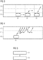
- Fig. 4 shows another diagram of a road with three lanes 40, 41, 42 to explain possible working schemes of the driver intention calculator 15.
- Fig. 4 the vehicle 43 starts on the right lane 40 and crosses to the central lane 41. However, the driver continues to move to the left lane 42. In this case the driver intention calculator 15 will wait for the final position of the vehicle 43. For example, the driver can move to the left lane 42 with at least the left vehicle wheels and then back to the central lane 41, if he wants to drive on the central lane 41, multiple crossings into the left lane can also be contemplated.
- the driver intention calculator 15 will monitor the steering angle and only turn off the turn lights 13, 14 if the steering angle normalizes and indicates a straight movement for a predetermined amount of time, e.g. 2 seconds. If, however, the driver moves farther into the left lane 42, e.g. because he wants to change to that lane 42, the driver intention calculator 15 can turn the turn lights 13, 14 off and on again to indicate that second lane change.
- Fig. 5 shows a flow diagram of a method for controlling turn lights 11, 12, 13, 14 in a vehicle 10, 33, 43, 53.
- the method comprises retrieving S1 information 3 about the vehicle movement and/or the vehicle surroundings, and controlling S2 the turn lights 11, 12, 13, 14 of the vehicle 10, 33, 43, 53 based on the retrieved information 3 about the vehicle movement and/or the vehicle surroundings.
- the information 3 about the vehicle movement can comprise a steering angle of the steering wheel of the vehicle 10, 33, 43, 53 and/or a vehicle speed.
- the information 3 about the vehicle surroundings can comprise road configuration information and/or information about detected lanes 30, 31, 32, 40, 41, 42, 50, 51, 52.
- Controlling S2 can comprise calculating based on the information 3 about the vehicle movement and/or the vehicle surroundings the driver's intention and controlling the turn lights 11, 12, 13, 14 of the vehicle 10, 33, 43, 53 according to the calculated driver's intention.
- Controlling can further comprise turning the turn lights 11, 12, 13, 14 for the respective direction on, if the intention to change the driving lane 30, 31, 32, 40, 41, 42, 50, 51, 52 or perform a turn is calculated and the turn lights 11, 12, 13, 14 are currently turned off.
- controlling can comprise turning the turn lights 11, 12, 13, 14 for the respective direction off, if the intention to stay on the current driving lane 30, 31, 32, 40, 41, 42, 50, 51, 52 is calculated and the turn lights 11, 12, 13, 14 are currently turned on.
- the intention to change the driving lane 30, 31, 32, 40, 41, 42, 50, 51, 52 and/or the intention to stay on the current driving lane 30, 31, 32, 40, 41, 42, 50, 51, 52 can be calculated based at least on the steering angle of the vehicle 10, 33, 43, 53 and the position of the vehicle 10, 33, 43, 53 in a currently used lane 30, 31, 32, 40, 41, 42, 50, 51, 52 of the road.
- the speed of the vehicle 10, 33, 43, 53 can e.g. be used as additional parameter.
Landscapes
- Engineering & Computer Science (AREA)
- Mechanical Engineering (AREA)
- Lighting Device Outwards From Vehicle And Optical Signal (AREA)
Abstract
Description
- The invention relates to a control unit for controlling turn lights in a vehicle, a vehicle and a respective method.
- Although applicable to any lighting system in a vehicle, the present invention will be described in combination with turn lights.
- Highly frequented roads often comprise three or more lanes. Vehicles moving on such roads can move freely from one lane to another. However other vehicles driving behind the lane-changing vehicle may be faster and the lane-changing vehicle may obstruct their trajectory.
- It is therefore helpful to indicate the intention to change the driving lane by a driver with the help of the turn lights. This will allow vehicles behind the lane-changing vehicle to adapt their driving accordingly, e.g. brake the vehicle or change to another lane.
- However, some drivers tend to forget the turn lights when changing lanes on a road.
- Accordingly, there is a need for an improved control of the vehicle's turn lights.
- A control unit for controlling turn lights in a vehicle comprises a communication interface, e.g. configured to connect the control unit to a vehicle bus of the vehicle, wherein information from other vehicle systems can be retrieved via the vehicle bus. The control unit further comprises a lighting controller coupled to the communication interface and configured to retrieve via the communication interface information about the vehicle movement and/or the vehicle surroundings, wherein the lighting controller is further configured to control the turn lights of the vehicle, also called indicator, based on the retrieved information about the vehicle movement and/or the vehicle surroundings.
- A vehicle comprises a control unit according to the present invention, and a vehicle bus, which connects the control unit to a number, e.g. one or more, of electronic vehicle systems.
- A method for controlling turn lights in a vehicle comprises retrieving information about the vehicle movement and/or the vehicle surroundings, e.g. via a vehicle bus, and controlling the turn lights of the vehicle based on the retrieved information about the vehicle movement and/or the vehicle surroundings.
- As explained above, some drivers tend to either not use or forget the turn lights of their vehicle. Especially on roads where vehicles travel at high speeds, like e.g. highways, not using the turn lights can lead to uncomfortable situations. The present invention therefore tries to assess a driving situation of a vehicle and control the turn lights accordingly.
- The control unit uses information that is already available in the vehicle and acquires this information via e.g. a vehicle bus from other vehicle systems or ECUs. The further vehicle systems can e.g. be a Lane Departure Warning System, LDWS, a steering angle sensor, a GPS or navigation system, a speed sensor or the like. The control unit can receive values about e.g. the steering angle, the vehicle speed, a possible lane departure or information about the lanes of the road e.g. directly from the respective vehicle system or indirectly via a central gateway or the like.
- Based on the acquired information the control unit can then judge whether it is necessary to turn on certain turn lights of the vehicle or not.
- The present invention therefore increases the vehicle safety especially on high speed roads and covers up driver deficiencies.
- Further embodiments of the present invention are subject of the further subclaims and of the following description, referring to the drawings.
- In a possible embodiment, the information about the vehicle movement can comprise a steering angle of the steering wheel of the vehicle and/or a vehicle speed. This information can be used to determine the intended course of the vehicle and the relevance of the steering angle. If for example the vehicle is driving very slowly, e.g. at the speed of a walking pedestrian, it can e.g. be assumed that the vehicle is circulating e.g. on a parking ground. In this situation turning on the turn lights may not be mandatory.
- Higher speeds, however, indicate that the use of turn lights may be helpful. Vehicles are usually driven at higher speeds on highways or at least on large roads, which may comprise a plurality of driving lanes in each direction. On such roads traffic coming from behind of the vehicle may be faster than the vehicle itself. Therefore, indicating to these upcoming vehicles the intention of the driver of the vehicle allows them to take evasive actions or slow down if necessary.
- In a possible embodiment, the information about the vehicle surroundings can comprise road configuration information, like e.g. the number of lanes of the road as stored in a navigation system, and/or information about detected lanes and/or information about a road trajectory.
- The information about the road configuration allows determining if the use of the turn lights is relevant in the respective driving situation of the vehicle. If e.g. the vehicle is driving on a single lane road, it is not necessary to indicate a lane change. If however the vehicle is e.g. driving in a residential zone and turns e.g. right at cross roads it can be helpful to indicate e.g. to bicycle drivers the intention to turn right via the turn lights.
- The information about detected lanes can e.g. comprise the number of lanes of the road as detected by a camera system, e.g. a lane departure warning, of the vehicle, and the lane which is currently used by the vehicle. The information about detected lanes can also comprise information about the position of the vehicle in the respective lane and e.g. if the vehicle or the wheels of the vehicle cross a lane boundary or marking.
- In a possible embodiment, the lighting controller can comprise a driver intention calculator, which can be configured to calculate based on the information about the vehicle movement and/or the vehicle surroundings the driver's intention and to control the turn lights of the vehicle according to the calculated driver's intention.
- The driving intention calculator can e.g. calculate the probability for a specific movement of the vehicle, e.g. a lane change to the left or right lane, a right or left turn at cross roads or the like. The probability can e.g. be calculated as a decimal value. A minimum threshold can e.g. be defined for assuming a certain driver intention based on the calculated probability. The probability can also be calculated as a binary value, wherein a positive binary value indicates that a driver intention has been recognized.
- In a possible embodiment, the driver intention calculator can be configured to turn the turn lights for the respective direction on, if the driver intention calculator calculates the intention to change the driving lane or perform a turn and the turn lights are currently turned off.
- If the intention to change the driving lane of the vehicle is detected, this intention should be notified by the turn lights to the following vehicles and their respective drivers. This will allow the drivers to slow down their vehicles or change to another lane of the road.
- The turn lights can then stay on as long as necessary. If e.g. it is determined that the vehicle changes from a right lane into a middle lane of a three lane road and the steering angle stays constant, the turn lights can further be turned on, to indicate a further change to the left lane.
- The driver intention calculator can also request information e.g. from a lane departure warning system or a navigation system in the vehicle. These system will e.g. detect if the road comprises a curve and provide respective information. In this case a steering angle corresponding to the curve will not trigger the turning on of the turn lights.
- In a possible embodiment, the driver intention calculator can be configured to turn the turn lights for the respective direction off, if the driver intention calculator calculates the intention to stay on the current driving lane and the turn lights are currently turned on.
- Drivers sometimes forget to turn of the turn lights after performing the respective driving manoeuvre, e.g. after changing a driving lane. Since the change of a driving lane usually only comprises a very small steering angle, the turn lights will not automatically be switched off by the turn light switch in the steering wheel of the vehicle.
- Therefore, if it is detected that the driver has no intention to further change the driving lane, e.g. directly after changing a lane, the turn lights can be turned off by the driver intention calculator.
- The driver intention calculator can e.g. monitor the steering angle of the vehicle. If the steering angle stays constant during and after a lane change, i.e. the driver is still steering to one side, the driver intention calculator can keep the turn lights on. The turn lights can then e.g. be turned off after a change to the leftmost lane of the road.
- However, the driver intention calculator can also turn the turn lights off, after the vehicle enters the central lane and turn the turn lights on again if the steering angle stays constant and the vehicle reaches the left boundary of the central lane. This will actively show the flowing vehicles that another lane change is intended and the turn light was not accidentally kept on.
- In a possible embodiment, the driver intention calculator can calculate the intention to change the driving lane and/or the intention to stay on the current driving lane based at least on the steering angle of the vehicle and the position of the vehicle in a currently used lane of the road.
- The driver of the vehicle can e.g. be driving on the right lane of a two or three lane highway. If the driver then turns the steering wheel to the left the driver intention calculator can further monitor the position of the vehicle in the lane. If the vehicle crosses the lane boundary to the left, the driver intention calculator can determine the driver's intention to change the driving lane.
- If in this case the turn lights are currently turned off, the driver intention calculator can turn on the turn lights to the left of the vehicle.
- The intention to turn left or right e.g. at cross roads can also be derived from a route of the vehicle, which is supplied by a navigation system of the vehicle.
- Further, the intention to e.g. change a driving lane can also be derived at least in part by information of a vehicle radar and objects detected by the vehicle radar in front of the vehicle. If e.g. a slow vehicles is detected in front of the vehicle in the same lane and the vehicle crosses the lane boundaries, a lane change is probably intended by the driver.
- Further, a threshold value can be defined, by which the vehicle has to cross the lane boundary. Such a threshold value can e.g. be defined in cm or m or in a percentage of the vehicle width.
- Further, a timeout value can be defined, which delays the turning on or off of the turn lights. If e.g. the vehicle crosses the lane boundary, a timer can be started and only if the vehicle crosses the lane boundary longer than defined by the timeout value, will the turn lights be turned on.
- Instead of or in addition to a timeout value a number of times a vehicle crosses a lane boundary can also be determined and compared to a threshold value.
- For a more complete understanding of the present invention and advantages thereof, reference is now made to the following description taken in conjunction with the accompanying drawings. The invention is explained in more detail below using exemplary embodiments which are specified in the schematic figures of the drawings, in which:
- Fig. 1
- shows a block diagram of an embodiment of a control unit according to an embodiment of the present invention;
- Fig. 2
- shows a block diagram of an embodiment of a vehicle according to an embodiment of the present invention;
- Fig. 3
- shows a diagram of a road to explain an embodiment of a control unit according to the present invention;
- Fig. 4
- shows a diagram of a road to explain an embodiment of a control unit according to the present invention; and
- Fig. 5
- shows a flow diagram of an embodiment of a method according to the present invention.
- In the figures like reference signs denote like elements unless stated otherwise.
-
Fig. 1 shows a block diagram of acontrol unit 1. Thecontrol unit 1 comprises acommunication interface 2 for retrievinginformation 3 from electronic vehicle systems (seeFig. 2 ). Theinformation 3 comprisesinformation 3 about the vehicle movement and the vehicle surroundings. Theinformation 3 is provided to alighting controller 4 of thecontrol unit 1. Thelighting controller 4 will determine based on theinformation 3, if it is necessary to turn on any of the turn lights of the vehicle (seeFig. 2 ). If thelighting controller 4 determines that it is necessary to turn on any of the turn lights, thelighting controller 4 will providespecific control signals 6 via thecontrol interface 5. The control signals 6 can e.g. be discrete currents or voltages, which are directly provided to the respective turn light. Alternatively, the control signals 6 can also be digital data signals, which instruct an ECU, Electronic Control Unit, to turn on the respective turn lights. The elements of thecontrol unit 1 can also be part of or at least partially integrated into such an ECU as Hardware or Software. - The
information 3 about the vehicle movement can comprise a steering angle of the steering wheel of the vehicle and a vehicle speed. Theinformation 3 about the vehicle surroundings can compriseroad configuration information 3 andinformation 3 about detected lanes. Any other information like route information from a navigation system or the like can also be part of theinformation 3. -
Fig. 2 shows a block diagram of avehicle 10 with acontrol unit 1. Thelighting controller 4 of thecontrol unit 1 inFig. 2 comprises adriver intention calculator 15. The control signals 6 are provided to the turn lights 11 - 14 of thevehicle 10, where the turn lights 11 and 12 indicate a turn to the right and the turn lights 13 and 14 indicate a turn to the left. - The
vehicle 10 further comprises a plurality of electronic vehicle systems 17 - 20. - The
system 17 is a lanedeparture warning system 17, which can inform that thevehicle 10 is departing from a lane either to the left or the right. In addition, the lanedeparture warning system 17 can also provide information about detected lanes (SeeFigs. 3 - 4 ) and the trajectory of the detected lanes. - The
system 18 is asteering angle sensor 18, which provides to thecontrol unit 1 the steering angle of the steering wheel of thevehicle 10. - The
system 19 is anavigation system 19, which can e.g. provide information about the number of lanes of the road thevehicle 10 is travelling on and their trajectories. - Finally, the
system 20 is aspeed sensor 20, either a dedicated sensor or an integrated sensor e.g. of a stability control system, which provides the vehicle speed. - With the help of the steering angle and the vehicle speed, the
driver intention calculator 15 can calculate the position of thevehicle 10 in the future. This information can be overlaid over information about the road and the lanes of the road thevehicle 10 is travelling on, to determine if the vehicle will leave a lane. - The
driver intention calculator 15 can calculate based on theinformation 3 the driver's intention and generate the control signals 6 accordingly. Thedriver intention calculator 15 can e.g. calculate the intention to change the driving lane or the intention to stay on the current driving lane based at least on the steering angle of thevehicle 10 and the position of thevehicle 10 in a currently used lane or the trajectory of the lane. Further, the speed of thevehicle 10 can also be used to calculate the future position of thevehicle 10. If the future position of thevehicle 10 is outside the lane, which thevehicle 10 is driving on, the respective turn lights 11, 12 or 13, 14 can be set accordingly. - To set the turn lights 11, 12 or 13, 14 accordingly, the
driver intention calculator 15 will turn the turn lights 11, 12 or 13, 14 for the respective direction on, only if thedriver intention calculator 15 calculates the intention to change the driving lane or perform a turn and the turn lights 11, 12, 13, 14 are currently turned off. In addition, thedriver intention calculator 15 will turn the turn lights 11, 12 or 13, 14 for the respective direction off, if thedriver intention calculator 15 calculates the intention to stay on the current driving lane and the turn lights 11, 12, 13, 14 are currently turned on. -
Fig. 3 shows a diagram of a road with threelanes driver intention calculator 15. - In a first position starting from the left of
Fig. 3 avehicle 33 is on theright lane 30 of the road. If thevehicle 33 stays in this position, e.g. for a predetermined amount of time, thedriver intention calculator 15 can turn off the turn lights 11, 12 or 13, 14, if they are currently turned on. - In a second position the
vehicle 33 will perform a change from theright lane 30 to thecentral lane 31 and then continue on thatlane 31. If prior to moving to thecentral lane 31, the steering angle and the speed of thevehicle 33 indicate to thedriver intention calculator 15 that thevehicle 33 is to move to anotherlane 31, thedriver intention calculator 15 will turn on the turn lights 13, 14 if the driver did not turn them on before. After moving to thecentral lane 31, thedriver intention calculator 15 will turn the turn lights 11, 12 off again, if the driver does not do so manually. There can be specific timeouts or threshold values for turning on and of the turn lights 13, 14, which will delay the switching. - In a third position the
vehicle 33 will perform a change from theright lane 30 to theleft lane 33. In this case, thedriver intention calculator 15 can turn on the turn lights 13, 14 when the movement of thevehicle 33 starts and keep the turn lights 13, 14 on, until thevehicle 33 reaches theleft lane 32. However, thedriver intention calculator 15 can also turn the turn lights 13, 14 off, when thevehicle 33 centers on thecentral lane 31 and turn them on again, when thevehicle 33 moves out of the center of thecentral lane 31 by a predetermined amount. -
Fig. 4 shows another diagram of a road with threelanes driver intention calculator 15. - In
Fig. 4 thevehicle 43 starts on theright lane 40 and crosses to thecentral lane 41. However, the driver continues to move to theleft lane 42. In this case thedriver intention calculator 15 will wait for the final position of thevehicle 43. For example, the driver can move to theleft lane 42 with at least the left vehicle wheels and then back to thecentral lane 41, if he wants to drive on thecentral lane 41, multiple crossings into the left lane can also be contemplated. Thedriver intention calculator 15 will monitor the steering angle and only turn off the turn lights 13, 14 if the steering angle normalizes and indicates a straight movement for a predetermined amount of time, e.g. 2 seconds. If, however, the driver moves farther into theleft lane 42, e.g. because he wants to change to thatlane 42, thedriver intention calculator 15 can turn the turn lights 13, 14 off and on again to indicate that second lane change. - Although the schemes of
Figs. 3 and 4 have been illustrated with lane changes starting from the right lanes, they can be applied to any lane change on any road with an arbitrary number of lanes and in any direction. -
Fig. 5 shows a flow diagram of a method for controllingturn lights vehicle - The method comprises retrieving
S1 information 3 about the vehicle movement and/or the vehicle surroundings, and controlling S2 the turn lights 11, 12, 13, 14 of thevehicle information 3 about the vehicle movement and/or the vehicle surroundings. - The
information 3 about the vehicle movement can comprise a steering angle of the steering wheel of thevehicle information 3 about the vehicle surroundings can comprise road configuration information and/or information about detectedlanes - Controlling S2 can comprise calculating based on the
information 3 about the vehicle movement and/or the vehicle surroundings the driver's intention and controlling the turn lights 11, 12, 13, 14 of thevehicle - Controlling can further comprise turning the turn lights 11, 12, 13, 14 for the respective direction on, if the intention to change the
driving lane current driving lane - Finally, the intention to change the
driving lane current driving lane vehicle vehicle lane vehicle - Although specific embodiments have been illustrated and described herein, it will be appreciated by those of ordinary skill in the art that a variety of alternate and/or equivalent implementations exist. It should be appreciated that the exemplary embodiment or exemplary embodiments are only examples, and are not intended to limit the scope, applicability, or configuration in any way. Rather, the foregoing summary and detailed description will provide those skilled in the art with a convenient road map for implementing at least one exemplary embodiment, it being understood that various changes may be made in the function and arrangement of elements described in an exemplary embodiment without departing from the scope as set forth in the appended claims and their legal equivalents. Generally, this application is intended to cover any adaptations or variations of the specific embodiments discussed herein.
- In the foregoing detailed description, various features are grouped together in one or more examples or examples for the purpose of streamlining the disclosure. It is understood that the above description is intended to be illustrative, and not restrictive. It is intended to cover all alternatives, modifications and equivalents as may be included within the scope of the invention. Many other examples will be apparent to one skilled in the art upon reviewing the above specification.
- Specific nomenclature used in the foregoing specification is used to provide a thorough understanding of the invention. However, it will be apparent to one skilled in the art in light of the specification provided herein that the specific details are not required in order to practice the invention. Thus, the foregoing descriptions of specific embodiments of the present invention are presented for purposes of illustration and description. They are not intended to be exhaustive or to limit the invention to the precise forms disclosed; obviously many modifications and variations are possible in view of the above teachings. The embodiments were chosen and described in order to best explain the principles of the invention and its practical applications, to thereby enable others skilled in the art to best utilize the invention and various embodiments with various modifications as are suited to the particular use contemplated. Throughout the specification, the terms "including" and "in which" are used as the plain-English equivalents of the respective terms "comprising" and "wherein," respectively. Moreover, the terms "first," "second," and "third," etc., are used merely as labels, and are not intended to impose numerical requirements on or to establish a certain ranking of importance of their objects.
-
- 1
- control unit
- 2
- communication interface
- 3
- information
- 4
- lighting controller
- 5
- control interface
- 6
- control signals
- 10
- vehicle
- 11, 12, 13, 14
- turn lights
- 15
- driver intention calculator
- 16
- vehicle bus
- 17, 18, 19, 20
- electronic vehicle systems
- 30, 31, 32
- lanes
- 33
- vehicle
- 40, 41, 42
- lanes
- 43
- vehicle
- 50, 51, 52
- lanes
- 53
- vehicle
- S1, S2
- method steps
Claims (15)
- Control unit (1) for controlling turn lights (11, 12, 13, 14) in a vehicle (10, 33, 43, 53), the control unit (1) comprising:a communication interface (2), anda lighting controller (4) coupled to the communication interface (2) and configured to retrieve via the communication interface (2) information (3) about the vehicle movement and/or the vehicle surroundings,wherein the lighting controller (4) is further configured to control the turn lights (11, 12, 13, 14) of the vehicle (10, 33, 43, 53) based on the retrieved information (3) about the vehicle movement and/or the vehicle surroundings.
- Control unit (1) according to claim 1,
wherein the information (3) about the vehicle movement comprises a steering angle of the steering wheel of the vehicle (10, 33, 43, 53) and/or a vehicle speed. - Control unit (1) according to anyone of the preceding claims, wherein the information (3) about the vehicle surroundings comprises road configuration information (3) and/or information (3) about detected lanes (30, 31, 32, 40, 41, 42, 50, 51, 52).
- Control unit (1) according to anyone of the preceding claims, wherein the lighting controller (4) comprises a driver intention calculator (15), which is configured to calculate based on the information (3) about the vehicle movement and/or the vehicle surroundings the drivers intention and to control the turn lights (11, 12, 13, 14) of the vehicle (10, 33, 43, 53) according to the calculated drivers intention.
- Control unit (1) according to claim 4, wherein the driver intention calculator (15) is configured to turn the turn lights (11, 12, 13, 14) for the respective direction on, if the driver intention calculator (15) calculates the intention to change the driving lane (30, 31, 32, 40, 41, 42, 50, 51, 52) or perform a turn and the turn lights (11, 12, 13, 14) are currently turned off.
- Control unit (1) according to any one of claims 4 and 5, wherein the driver intention calculator (15) is configured to turn the turn lights (11, 12, 13, 14) for the respective direction off, if the driver intention calculator (15) calculates the intention to stay on the current driving lane (30, 31, 32, 40, 41, 42, 50, 51, 52) and the turn lights (11, 12, 13, 14) are currently turned on.
- Control unit (1) according to claims 2 to 6, wherein the driver intention calculator (15) calculates the intention to change the driving lane (30, 31, 32, 40, 41, 42, 50, 51, 52) and/or the intention to stay on the current driving lane (30, 31, 32, 40, 41, 42, 50, 51, 52) based at least on the steering angle of the vehicle (10, 33, 43, 53) and the position of the vehicle (10, 33, 43, 53) in a currently used lane (30, 31, 32, 40, 41, 42, 50, 51, 52) of the road.
- Vehicle (10, 33, 43, 53) comprising
a control unit (1) according to any one of claims 1 to 7, and
a vehicle bus (16), which connects the control unit (1) to a number of electronic vehicle systems (17, 18, 19, 20). - Method for controlling turn lights (11, 12, 13, 14) in a vehicle (10, 33, 43, 53), the method comprising:retrieving (S1) information (3) about the vehicle movement and/or the vehicle surroundings, andcontrolling (S2) the turn lights (11, 12, 13, 14) of the vehicle (10, 33, 43, 53) based on the retrieved information (3) about the vehicle movement and/or the vehicle surroundings.
- Method according to claim 9,
wherein the information (3) about the vehicle movement comprises a steering angle of the steering wheel of the vehicle (10, 33, 43, 53) and/or a vehicle speed. - Method according to anyone of the preceding claims 9 and 10, wherein the information (3) about the vehicle surroundings comprises road configuration information (3) and/or information (3) about detected lanes (30, 31, 32, 40, 41, 42, 50, 51, 52).
- Method according to anyone of the preceding claims 9 to 11, wherein controlling (S2) comprises calculating based on the information (3) about the vehicle movement and/or the vehicle surroundings the drivers intention and controlling the turn lights (11, 12, 13, 14) of the vehicle (10, 33, 43, 53) according to the calculated drivers intention.
- Method according to claim 12, wherein controlling (S2) comprises turning the turn lights (11, 12, 13, 14) for the respective direction on, if the intention to change the driving lane (30, 31, 32, 40, 41, 42, 50, 51, 52) or perform a turn is calculated and the turn lights (11, 12, 13, 14) are currently turned off.
- Method according to any one of claims 12 and 13, wherein controlling (S2) comprises turning the turn lights (11, 12, 13, 14) for the respective direction off, if the intention to stay on the current driving lane (30, 31, 32, 40, 41, 42, 50, 51, 52) is calculated and the turn lights (11, 12, 13, 14) are currently turned on.
- Method according to claims 10 to 14, wherein the intention to change the driving lane (30, 31, 32, 40, 41, 42, 50, 51, 52) and/or the intention to stay on the current driving lane (30, 31, 32, 40, 41, 42, 50, 51, 52) is calculated based at least on the steering angle of the vehicle (10, 33, 43, 53) and the position of the vehicle (10, 33, 43, 53) in a currently used lane (30, 31, 32, 40, 41, 42, 50, 51, 52) of the road.
Priority Applications (1)
| Application Number | Priority Date | Filing Date | Title |
|---|---|---|---|
| EP16202160.4A EP3330128B1 (en) | 2016-12-05 | 2016-12-05 | Control unit, vehicle and method |
Applications Claiming Priority (1)
| Application Number | Priority Date | Filing Date | Title |
|---|---|---|---|
| EP16202160.4A EP3330128B1 (en) | 2016-12-05 | 2016-12-05 | Control unit, vehicle and method |
Publications (2)
| Publication Number | Publication Date |
|---|---|
| EP3330128A1 true EP3330128A1 (en) | 2018-06-06 |
| EP3330128B1 EP3330128B1 (en) | 2022-03-30 |
Family
ID=57542718
Family Applications (1)
| Application Number | Title | Priority Date | Filing Date |
|---|---|---|---|
| EP16202160.4A Active EP3330128B1 (en) | 2016-12-05 | 2016-12-05 | Control unit, vehicle and method |
Country Status (1)
| Country | Link |
|---|---|
| EP (1) | EP3330128B1 (en) |
Cited By (2)
| Publication number | Priority date | Publication date | Assignee | Title |
|---|---|---|---|---|
| CN114312785A (en) * | 2021-12-15 | 2022-04-12 | 上汽大众汽车有限公司 | Lane changing auxiliary system and method for vehicle |
| CN115042699A (en) * | 2021-10-14 | 2022-09-13 | 长城汽车股份有限公司 | Control method and device for steering lamp of vehicle and vehicle |
Citations (4)
| Publication number | Priority date | Publication date | Assignee | Title |
|---|---|---|---|---|
| DE10251357A1 (en) * | 2002-11-05 | 2004-05-13 | Daimlerchrysler Ag | Automatic operating method for automobile trafficator display with evaluation of data for identification of turning or lane changing maneuver |
| US7889065B2 (en) * | 2008-01-04 | 2011-02-15 | Smith Alexander E | Method and apparatus to determine vehicle intent |
| US20130265152A1 (en) * | 2004-03-15 | 2013-10-10 | Anita Au | Automatic signaling system for vehicles |
| US9079499B1 (en) * | 2011-11-22 | 2015-07-14 | Sara Elyse Raubvogel | Automatic activation of turn signals in a vehicle |
-
2016
- 2016-12-05 EP EP16202160.4A patent/EP3330128B1/en active Active
Patent Citations (4)
| Publication number | Priority date | Publication date | Assignee | Title |
|---|---|---|---|---|
| DE10251357A1 (en) * | 2002-11-05 | 2004-05-13 | Daimlerchrysler Ag | Automatic operating method for automobile trafficator display with evaluation of data for identification of turning or lane changing maneuver |
| US20130265152A1 (en) * | 2004-03-15 | 2013-10-10 | Anita Au | Automatic signaling system for vehicles |
| US7889065B2 (en) * | 2008-01-04 | 2011-02-15 | Smith Alexander E | Method and apparatus to determine vehicle intent |
| US9079499B1 (en) * | 2011-11-22 | 2015-07-14 | Sara Elyse Raubvogel | Automatic activation of turn signals in a vehicle |
Cited By (2)
| Publication number | Priority date | Publication date | Assignee | Title |
|---|---|---|---|---|
| CN115042699A (en) * | 2021-10-14 | 2022-09-13 | 长城汽车股份有限公司 | Control method and device for steering lamp of vehicle and vehicle |
| CN114312785A (en) * | 2021-12-15 | 2022-04-12 | 上汽大众汽车有限公司 | Lane changing auxiliary system and method for vehicle |
Also Published As
| Publication number | Publication date |
|---|---|
| EP3330128B1 (en) | 2022-03-30 |
Similar Documents
| Publication | Publication Date | Title |
|---|---|---|
| US12060073B2 (en) | Control system for vehicle and control method for vehicle | |
| CN113631448B (en) | Vehicle control method and vehicle control device | |
| US11498563B2 (en) | Vehicle control device, vehicle control method, and storage medium | |
| CN108216244B (en) | Vehicle control device | |
| US10074279B1 (en) | Inference-aware motion planning | |
| EP3372466B1 (en) | Autonomous vehicle operating apparatus and autonomous vehicle operating method | |
| EP3690586A1 (en) | Method and device for remote-controlling autonomous vehicle capable of changing driving mode between autonomous driving mode and manual driving mode | |
| KR102137933B1 (en) | Method for controlling cornering of vehicle and apparatus thereof | |
| US12539850B2 (en) | Method for operating a motor vehicle, and motor vehicle | |
| JPWO2019043847A1 (en) | Travel control device, vehicle, and travel control method | |
| US9026356B2 (en) | Vehicle navigation system and method | |
| US20190283756A1 (en) | Vehicle systems and methods for providing turn assistance at an intersection | |
| US10435020B2 (en) | Lane keeping support on roads covered by snow | |
| JP2015206655A (en) | Automatic driving plan display device and program for automatic driving plan display device | |
| JP2020142675A (en) | Vehicle control device | |
| CN107406078A (en) | Method for performing a lane change in a motor vehicle | |
| US7292920B2 (en) | Method and device for lateral guidance of a vehicle | |
| JP2021525678A (en) | Driver support system | |
| US11137759B2 (en) | Systems and methods of level 2 autonomous vehicle driving on multiply digitized roads | |
| WO2019142312A1 (en) | Vehicle control device, vehicle having same, and control method | |
| US11685404B2 (en) | Autonomous driving control method and autonomous driving control system | |
| JP6548029B2 (en) | Automatic driving system | |
| JP2017174282A (en) | Drive control device, drive control method, drive control program, and recording medium | |
| CN108829096A (en) | A kind of method and system that control pilotless automobile turns to | |
| JP2020045039A (en) | Vehicle control method and vehicle control device |
Legal Events
| Date | Code | Title | Description |
|---|---|---|---|
| PUAI | Public reference made under article 153(3) epc to a published international application that has entered the european phase |
Free format text: ORIGINAL CODE: 0009012 |
|
| STAA | Information on the status of an ep patent application or granted ep patent |
Free format text: STATUS: THE APPLICATION HAS BEEN PUBLISHED |
|
| AK | Designated contracting states |
Kind code of ref document: A1 Designated state(s): AL AT BE BG CH CY CZ DE DK EE ES FI FR GB GR HR HU IE IS IT LI LT LU LV MC MK MT NL NO PL PT RO RS SE SI SK SM TR |
|
| AX | Request for extension of the european patent |
Extension state: BA ME |
|
| STAA | Information on the status of an ep patent application or granted ep patent |
Free format text: STATUS: REQUEST FOR EXAMINATION WAS MADE |
|
| 17P | Request for examination filed |
Effective date: 20181206 |
|
| RBV | Designated contracting states (corrected) |
Designated state(s): AL AT BE BG CH CY CZ DE DK EE ES FI FR GB GR HR HU IE IS IT LI LT LU LV MC MK MT NL NO PL PT RO RS SE SI SK SM TR |
|
| RAP1 | Party data changed (applicant data changed or rights of an application transferred) |
Owner name: CONTINENTAL AUTOMOTIVE GMBH |
|
| GRAP | Despatch of communication of intention to grant a patent |
Free format text: ORIGINAL CODE: EPIDOSNIGR1 |
|
| STAA | Information on the status of an ep patent application or granted ep patent |
Free format text: STATUS: GRANT OF PATENT IS INTENDED |
|
| INTG | Intention to grant announced |
Effective date: 20211215 |
|
| GRAS | Grant fee paid |
Free format text: ORIGINAL CODE: EPIDOSNIGR3 |
|
| GRAA | (expected) grant |
Free format text: ORIGINAL CODE: 0009210 |
|
| STAA | Information on the status of an ep patent application or granted ep patent |
Free format text: STATUS: THE PATENT HAS BEEN GRANTED |
|
| AK | Designated contracting states |
Kind code of ref document: B1 Designated state(s): AL AT BE BG CH CY CZ DE DK EE ES FI FR GB GR HR HU IE IS IT LI LT LU LV MC MK MT NL NO PL PT RO RS SE SI SK SM TR |
|
| REG | Reference to a national code |
Ref country code: GB Ref legal event code: FG4D |
|
| REG | Reference to a national code |
Ref country code: CH Ref legal event code: EP |
|
| REG | Reference to a national code |
Ref country code: AT Ref legal event code: REF Ref document number: 1478902 Country of ref document: AT Kind code of ref document: T Effective date: 20220415 |
|
| REG | Reference to a national code |
Ref country code: DE Ref legal event code: R096 Ref document number: 602016070449 Country of ref document: DE |
|
| REG | Reference to a national code |
Ref country code: IE Ref legal event code: FG4D |
|
| REG | Reference to a national code |
Ref country code: LT Ref legal event code: MG9D |
|
| REG | Reference to a national code |
Ref country code: DE Ref legal event code: R081 Ref document number: 602016070449 Country of ref document: DE Owner name: CONTINENTAL AUTONOMOUS MOBILITY GERMANY GMBH, DE Free format text: FORMER OWNER: CONTINENTAL AUTOMOTIVE GMBH, 30165 HANNOVER, DE Ref country code: DE Ref legal event code: R081 Ref document number: 602016070449 Country of ref document: DE Owner name: AUMOVIO AUTONOMOUS MOBILITY GERMANY GMBH, DE Free format text: FORMER OWNER: CONTINENTAL AUTOMOTIVE GMBH, 30165 HANNOVER, DE |
|
| PG25 | Lapsed in a contracting state [announced via postgrant information from national office to epo] |
Ref country code: SE Free format text: LAPSE BECAUSE OF FAILURE TO SUBMIT A TRANSLATION OF THE DESCRIPTION OR TO PAY THE FEE WITHIN THE PRESCRIBED TIME-LIMIT Effective date: 20220330 Ref country code: RS Free format text: LAPSE BECAUSE OF FAILURE TO SUBMIT A TRANSLATION OF THE DESCRIPTION OR TO PAY THE FEE WITHIN THE PRESCRIBED TIME-LIMIT Effective date: 20220330 Ref country code: NO Free format text: LAPSE BECAUSE OF FAILURE TO SUBMIT A TRANSLATION OF THE DESCRIPTION OR TO PAY THE FEE WITHIN THE PRESCRIBED TIME-LIMIT Effective date: 20220630 Ref country code: LT Free format text: LAPSE BECAUSE OF FAILURE TO SUBMIT A TRANSLATION OF THE DESCRIPTION OR TO PAY THE FEE WITHIN THE PRESCRIBED TIME-LIMIT Effective date: 20220330 Ref country code: HR Free format text: LAPSE BECAUSE OF FAILURE TO SUBMIT A TRANSLATION OF THE DESCRIPTION OR TO PAY THE FEE WITHIN THE PRESCRIBED TIME-LIMIT Effective date: 20220330 Ref country code: BG Free format text: LAPSE BECAUSE OF FAILURE TO SUBMIT A TRANSLATION OF THE DESCRIPTION OR TO PAY THE FEE WITHIN THE PRESCRIBED TIME-LIMIT Effective date: 20220630 |
|
| REG | Reference to a national code |
Ref country code: NL Ref legal event code: MP Effective date: 20220330 |
|
| REG | Reference to a national code |
Ref country code: AT Ref legal event code: MK05 Ref document number: 1478902 Country of ref document: AT Kind code of ref document: T Effective date: 20220330 |
|
| PG25 | Lapsed in a contracting state [announced via postgrant information from national office to epo] |
Ref country code: LV Free format text: LAPSE BECAUSE OF FAILURE TO SUBMIT A TRANSLATION OF THE DESCRIPTION OR TO PAY THE FEE WITHIN THE PRESCRIBED TIME-LIMIT Effective date: 20220330 Ref country code: GR Free format text: LAPSE BECAUSE OF FAILURE TO SUBMIT A TRANSLATION OF THE DESCRIPTION OR TO PAY THE FEE WITHIN THE PRESCRIBED TIME-LIMIT Effective date: 20220701 Ref country code: FI Free format text: LAPSE BECAUSE OF FAILURE TO SUBMIT A TRANSLATION OF THE DESCRIPTION OR TO PAY THE FEE WITHIN THE PRESCRIBED TIME-LIMIT Effective date: 20220330 |
|
| PG25 | Lapsed in a contracting state [announced via postgrant information from national office to epo] |
Ref country code: NL Free format text: LAPSE BECAUSE OF FAILURE TO SUBMIT A TRANSLATION OF THE DESCRIPTION OR TO PAY THE FEE WITHIN THE PRESCRIBED TIME-LIMIT Effective date: 20220330 |
|
| PG25 | Lapsed in a contracting state [announced via postgrant information from national office to epo] |
Ref country code: SM Free format text: LAPSE BECAUSE OF FAILURE TO SUBMIT A TRANSLATION OF THE DESCRIPTION OR TO PAY THE FEE WITHIN THE PRESCRIBED TIME-LIMIT Effective date: 20220330 Ref country code: SK Free format text: LAPSE BECAUSE OF FAILURE TO SUBMIT A TRANSLATION OF THE DESCRIPTION OR TO PAY THE FEE WITHIN THE PRESCRIBED TIME-LIMIT Effective date: 20220330 Ref country code: RO Free format text: LAPSE BECAUSE OF FAILURE TO SUBMIT A TRANSLATION OF THE DESCRIPTION OR TO PAY THE FEE WITHIN THE PRESCRIBED TIME-LIMIT Effective date: 20220330 Ref country code: PT Free format text: LAPSE BECAUSE OF FAILURE TO SUBMIT A TRANSLATION OF THE DESCRIPTION OR TO PAY THE FEE WITHIN THE PRESCRIBED TIME-LIMIT Effective date: 20220801 Ref country code: ES Free format text: LAPSE BECAUSE OF FAILURE TO SUBMIT A TRANSLATION OF THE DESCRIPTION OR TO PAY THE FEE WITHIN THE PRESCRIBED TIME-LIMIT Effective date: 20220330 Ref country code: EE Free format text: LAPSE BECAUSE OF FAILURE TO SUBMIT A TRANSLATION OF THE DESCRIPTION OR TO PAY THE FEE WITHIN THE PRESCRIBED TIME-LIMIT Effective date: 20220330 Ref country code: CZ Free format text: LAPSE BECAUSE OF FAILURE TO SUBMIT A TRANSLATION OF THE DESCRIPTION OR TO PAY THE FEE WITHIN THE PRESCRIBED TIME-LIMIT Effective date: 20220330 Ref country code: AT Free format text: LAPSE BECAUSE OF FAILURE TO SUBMIT A TRANSLATION OF THE DESCRIPTION OR TO PAY THE FEE WITHIN THE PRESCRIBED TIME-LIMIT Effective date: 20220330 |
|
| PG25 | Lapsed in a contracting state [announced via postgrant information from national office to epo] |
Ref country code: PL Free format text: LAPSE BECAUSE OF FAILURE TO SUBMIT A TRANSLATION OF THE DESCRIPTION OR TO PAY THE FEE WITHIN THE PRESCRIBED TIME-LIMIT Effective date: 20220330 Ref country code: IS Free format text: LAPSE BECAUSE OF FAILURE TO SUBMIT A TRANSLATION OF THE DESCRIPTION OR TO PAY THE FEE WITHIN THE PRESCRIBED TIME-LIMIT Effective date: 20220730 Ref country code: AL Free format text: LAPSE BECAUSE OF FAILURE TO SUBMIT A TRANSLATION OF THE DESCRIPTION OR TO PAY THE FEE WITHIN THE PRESCRIBED TIME-LIMIT Effective date: 20220330 |
|
| REG | Reference to a national code |
Ref country code: DE Ref legal event code: R097 Ref document number: 602016070449 Country of ref document: DE |
|
| PG25 | Lapsed in a contracting state [announced via postgrant information from national office to epo] |
Ref country code: DK Free format text: LAPSE BECAUSE OF FAILURE TO SUBMIT A TRANSLATION OF THE DESCRIPTION OR TO PAY THE FEE WITHIN THE PRESCRIBED TIME-LIMIT Effective date: 20220330 |
|
| PLBE | No opposition filed within time limit |
Free format text: ORIGINAL CODE: 0009261 |
|
| STAA | Information on the status of an ep patent application or granted ep patent |
Free format text: STATUS: NO OPPOSITION FILED WITHIN TIME LIMIT |
|
| 26N | No opposition filed |
Effective date: 20230103 |
|
| PG25 | Lapsed in a contracting state [announced via postgrant information from national office to epo] |
Ref country code: SI Free format text: LAPSE BECAUSE OF FAILURE TO SUBMIT A TRANSLATION OF THE DESCRIPTION OR TO PAY THE FEE WITHIN THE PRESCRIBED TIME-LIMIT Effective date: 20220330 |
|
| PG25 | Lapsed in a contracting state [announced via postgrant information from national office to epo] |
Ref country code: IT Free format text: LAPSE BECAUSE OF FAILURE TO SUBMIT A TRANSLATION OF THE DESCRIPTION OR TO PAY THE FEE WITHIN THE PRESCRIBED TIME-LIMIT Effective date: 20220330 |
|
| REG | Reference to a national code |
Ref country code: CH Ref legal event code: PL |
|
| GBPC | Gb: european patent ceased through non-payment of renewal fee |
Effective date: 20221205 |
|
| REG | Reference to a national code |
Ref country code: BE Ref legal event code: MM Effective date: 20221231 |
|
| PG25 | Lapsed in a contracting state [announced via postgrant information from national office to epo] |
Ref country code: LU Free format text: LAPSE BECAUSE OF NON-PAYMENT OF DUE FEES Effective date: 20221205 |
|
| PG25 | Lapsed in a contracting state [announced via postgrant information from national office to epo] |
Ref country code: LI Free format text: LAPSE BECAUSE OF NON-PAYMENT OF DUE FEES Effective date: 20221231 Ref country code: IE Free format text: LAPSE BECAUSE OF NON-PAYMENT OF DUE FEES Effective date: 20221205 Ref country code: GB Free format text: LAPSE BECAUSE OF NON-PAYMENT OF DUE FEES Effective date: 20221205 Ref country code: CH Free format text: LAPSE BECAUSE OF NON-PAYMENT OF DUE FEES Effective date: 20221231 |
|
| PG25 | Lapsed in a contracting state [announced via postgrant information from national office to epo] |
Ref country code: BE Free format text: LAPSE BECAUSE OF NON-PAYMENT OF DUE FEES Effective date: 20221231 |
|
| PG25 | Lapsed in a contracting state [announced via postgrant information from national office to epo] |
Ref country code: HU Free format text: LAPSE BECAUSE OF FAILURE TO SUBMIT A TRANSLATION OF THE DESCRIPTION OR TO PAY THE FEE WITHIN THE PRESCRIBED TIME-LIMIT; INVALID AB INITIO Effective date: 20161205 |
|
| PG25 | Lapsed in a contracting state [announced via postgrant information from national office to epo] |
Ref country code: CY Free format text: LAPSE BECAUSE OF FAILURE TO SUBMIT A TRANSLATION OF THE DESCRIPTION OR TO PAY THE FEE WITHIN THE PRESCRIBED TIME-LIMIT Effective date: 20220330 |
|
| PG25 | Lapsed in a contracting state [announced via postgrant information from national office to epo] |
Ref country code: MK Free format text: LAPSE BECAUSE OF FAILURE TO SUBMIT A TRANSLATION OF THE DESCRIPTION OR TO PAY THE FEE WITHIN THE PRESCRIBED TIME-LIMIT Effective date: 20220330 |
|
| PG25 | Lapsed in a contracting state [announced via postgrant information from national office to epo] |
Ref country code: MC Free format text: LAPSE BECAUSE OF FAILURE TO SUBMIT A TRANSLATION OF THE DESCRIPTION OR TO PAY THE FEE WITHIN THE PRESCRIBED TIME-LIMIT Effective date: 20220330 |
|
| PG25 | Lapsed in a contracting state [announced via postgrant information from national office to epo] |
Ref country code: TR Free format text: LAPSE BECAUSE OF FAILURE TO SUBMIT A TRANSLATION OF THE DESCRIPTION OR TO PAY THE FEE WITHIN THE PRESCRIBED TIME-LIMIT Effective date: 20220330 Ref country code: MC Free format text: LAPSE BECAUSE OF FAILURE TO SUBMIT A TRANSLATION OF THE DESCRIPTION OR TO PAY THE FEE WITHIN THE PRESCRIBED TIME-LIMIT Effective date: 20220330 |
|
| PG25 | Lapsed in a contracting state [announced via postgrant information from national office to epo] |
Ref country code: MT Free format text: LAPSE BECAUSE OF FAILURE TO SUBMIT A TRANSLATION OF THE DESCRIPTION OR TO PAY THE FEE WITHIN THE PRESCRIBED TIME-LIMIT Effective date: 20220330 |
|
| REG | Reference to a national code |
Ref country code: DE Ref legal event code: R081 Ref document number: 602016070449 Country of ref document: DE Owner name: AUMOVIO AUTONOMOUS MOBILITY GERMANY GMBH, DE Free format text: FORMER OWNER: CONTINENTAL AUTONOMOUS MOBILITY GERMANY GMBH, 85057 INGOLSTADT, DE |
|
| PGFP | Annual fee paid to national office [announced via postgrant information from national office to epo] |
Ref country code: FR Payment date: 20251223 Year of fee payment: 10 |
|
| PGFP | Annual fee paid to national office [announced via postgrant information from national office to epo] |
Ref country code: DE Payment date: 20251231 Year of fee payment: 10 |