EP3330100A1 - Structurally supported tire - Google Patents
Structurally supported tire Download PDFInfo
- Publication number
- EP3330100A1 EP3330100A1 EP17204386.1A EP17204386A EP3330100A1 EP 3330100 A1 EP3330100 A1 EP 3330100A1 EP 17204386 A EP17204386 A EP 17204386A EP 3330100 A1 EP3330100 A1 EP 3330100A1
- Authority
- EP
- European Patent Office
- Prior art keywords
- rings
- tire
- fabric
- layer
- set forth
- Prior art date
- Legal status (The legal status is an assumption and is not a legal conclusion. Google has not performed a legal analysis and makes no representation as to the accuracy of the status listed.)
- Withdrawn
Links
- 239000004744 fabric Substances 0.000 claims description 60
- 239000000835 fiber Substances 0.000 claims description 27
- 230000002787 reinforcement Effects 0.000 claims description 23
- 239000002184 metal Substances 0.000 claims description 4
- 239000004033 plastic Substances 0.000 claims description 4
- 229920003023 plastic Polymers 0.000 claims description 4
- 239000005060 rubber Substances 0.000 claims description 4
- 239000010410 layer Substances 0.000 description 53
- 238000010276 construction Methods 0.000 description 12
- 239000000463 material Substances 0.000 description 8
- 125000006850 spacer group Chemical group 0.000 description 3
- 239000011324 bead Substances 0.000 description 2
- 229920006253 high performance fiber Polymers 0.000 description 2
- 238000012423 maintenance Methods 0.000 description 2
- 230000003014 reinforcing effect Effects 0.000 description 2
- 229920002748 Basalt fiber Polymers 0.000 description 1
- 229920000049 Carbon (fiber) Polymers 0.000 description 1
- 239000004698 Polyethylene Substances 0.000 description 1
- 229920000297 Rayon Polymers 0.000 description 1
- 239000012790 adhesive layer Substances 0.000 description 1
- 238000013459 approach Methods 0.000 description 1
- 229920006231 aramid fiber Polymers 0.000 description 1
- 239000004917 carbon fiber Substances 0.000 description 1
- 239000003575 carbonaceous material Substances 0.000 description 1
- 239000002131 composite material Substances 0.000 description 1
- 150000001875 compounds Chemical class 0.000 description 1
- 230000006835 compression Effects 0.000 description 1
- 238000007906 compression Methods 0.000 description 1
- 230000003247 decreasing effect Effects 0.000 description 1
- 230000001419 dependent effect Effects 0.000 description 1
- 239000002657 fibrous material Substances 0.000 description 1
- 239000000945 filler Substances 0.000 description 1
- 229920005570 flexible polymer Polymers 0.000 description 1
- 239000006260 foam Substances 0.000 description 1
- 239000000446 fuel Substances 0.000 description 1
- 239000003365 glass fiber Substances 0.000 description 1
- 239000003562 lightweight material Substances 0.000 description 1
- 239000007769 metal material Substances 0.000 description 1
- VNWKTOKETHGBQD-UHFFFAOYSA-N methane Chemical compound C VNWKTOKETHGBQD-UHFFFAOYSA-N 0.000 description 1
- 238000012544 monitoring process Methods 0.000 description 1
- 229920001778 nylon Polymers 0.000 description 1
- 229920000728 polyester Polymers 0.000 description 1
- -1 polyethylene Polymers 0.000 description 1
- 229920000573 polyethylene Polymers 0.000 description 1
- 229920000642 polymer Polymers 0.000 description 1
- 239000002861 polymer material Substances 0.000 description 1
- 239000002964 rayon Substances 0.000 description 1
- 238000005096 rolling process Methods 0.000 description 1
- 239000012812 sealant material Substances 0.000 description 1
- 239000007787 solid Substances 0.000 description 1
- 239000004753 textile Substances 0.000 description 1
Images





Classifications
-
- B—PERFORMING OPERATIONS; TRANSPORTING
- B60—VEHICLES IN GENERAL
- B60B—VEHICLE WHEELS; CASTORS; AXLES FOR WHEELS OR CASTORS; INCREASING WHEEL ADHESION
- B60B9/00—Wheels of high resiliency, e.g. with conical interacting pressure-surfaces
- B60B9/26—Wheels of high resiliency, e.g. with conical interacting pressure-surfaces comprising resilient spokes
-
- B—PERFORMING OPERATIONS; TRANSPORTING
- B60—VEHICLES IN GENERAL
- B60C—VEHICLE TYRES; TYRE INFLATION; TYRE CHANGING; CONNECTING VALVES TO INFLATABLE ELASTIC BODIES IN GENERAL; DEVICES OR ARRANGEMENTS RELATED TO TYRES
- B60C7/00—Non-inflatable or solid tyres
-
- B—PERFORMING OPERATIONS; TRANSPORTING
- B60—VEHICLES IN GENERAL
- B60C—VEHICLE TYRES; TYRE INFLATION; TYRE CHANGING; CONNECTING VALVES TO INFLATABLE ELASTIC BODIES IN GENERAL; DEVICES OR ARRANGEMENTS RELATED TO TYRES
- B60C7/00—Non-inflatable or solid tyres
- B60C7/10—Non-inflatable or solid tyres characterised by means for increasing resiliency
- B60C7/14—Non-inflatable or solid tyres characterised by means for increasing resiliency using springs
-
- B—PERFORMING OPERATIONS; TRANSPORTING
- B60—VEHICLES IN GENERAL
- B60C—VEHICLE TYRES; TYRE INFLATION; TYRE CHANGING; CONNECTING VALVES TO INFLATABLE ELASTIC BODIES IN GENERAL; DEVICES OR ARRANGEMENTS RELATED TO TYRES
- B60C7/00—Non-inflatable or solid tyres
- B60C7/10—Non-inflatable or solid tyres characterised by means for increasing resiliency
- B60C7/14—Non-inflatable or solid tyres characterised by means for increasing resiliency using springs
- B60C7/146—Non-inflatable or solid tyres characterised by means for increasing resiliency using springs extending substantially radially, e.g. like spokes
-
- B—PERFORMING OPERATIONS; TRANSPORTING
- B60—VEHICLES IN GENERAL
- B60C—VEHICLE TYRES; TYRE INFLATION; TYRE CHANGING; CONNECTING VALVES TO INFLATABLE ELASTIC BODIES IN GENERAL; DEVICES OR ARRANGEMENTS RELATED TO TYRES
- B60C7/00—Non-inflatable or solid tyres
- B60C7/10—Non-inflatable or solid tyres characterised by means for increasing resiliency
- B60C7/14—Non-inflatable or solid tyres characterised by means for increasing resiliency using springs
- B60C7/16—Non-inflatable or solid tyres characterised by means for increasing resiliency using springs of helical or flat coil form
- B60C7/18—Non-inflatable or solid tyres characterised by means for increasing resiliency using springs of helical or flat coil form disposed radially relative to wheel axis
-
- B—PERFORMING OPERATIONS; TRANSPORTING
- B60—VEHICLES IN GENERAL
- B60C—VEHICLE TYRES; TYRE INFLATION; TYRE CHANGING; CONNECTING VALVES TO INFLATABLE ELASTIC BODIES IN GENERAL; DEVICES OR ARRANGEMENTS RELATED TO TYRES
- B60C7/00—Non-inflatable or solid tyres
- B60C7/22—Non-inflatable or solid tyres having inlays other than for increasing resiliency, e.g. for armouring
Definitions
- the present invention relates to a tire, and more particularly, to a radial passenger tire or a high performance tire having a three dimensional spacer component. It provides a structurally supported tire as a lightweight tire.
- the pneumatic tire has been the solution of choice for vehicular mobility for over a century. Modern belted, radial carcass, pneumatic tires are remarkable products that provide an effective means for supporting applied loads while allowing reasonable vertical and lateral compliance.
- the pneumatic tire obtains its mechanical attributes largely due to the action of internal air pressure in the tire cavity. Reaction to the inflation pressure corrects rigidities to the belt and carcass components. Inflation pressure is then one of the most important design parameters for a pneumatic tire.
- a tire designed to operate without inflation pressure may eliminate many of the problems and compromises associated with a pneumatic tire. Neither pressure maintenance nor pressure monitoring is required. Structurally supported tires such as solid tires or other elastomeric structures to date have not provided the levels of performance required from a conventional pneumatic tire. A structurally supported tire solution that delivers pneumatic tire-like performance would be a desirous improvement.
- the invention relates to a tire in accordance with claim 1.
- a first tire in accordance with the present invention has an axis of rotation.
- the first tire includes a circular tread band, a circular hub for attachment to an axle, and a structure including a plurality of annular rings interconnecting the tread band and the hub and transferring a load from the tread band to the hub.
- a first group of rings are disposed axially adjacent each other and a second group of rings are concentric and disposed radially adjacent each other.
- the rings of the plurality of rings include layers of fabric.
- the rings of the plurality of rings include reinforcement members of yarn, filaments, fibers, and/or fabric.
- the rings of the plurality of rings include layers connected together by reinforcement members.
- the rings of the plurality of rings include knitted layers.
- the rings of the plurality of rings include an "open" layer of individual pile fibers connecting a first layer of fabric and a second layer of fabric.
- the rings of the plurality of rings include a "closed" layer of fabric piles connecting a first layer and a second layer.
- the plurality of rings are interconnected by annular bands.
- the annular bands are constructed or rubber, of plastic or of metal.
- a second tire in accordance with the present invention has an axis of rotation.
- the second tire includes a circular tread band, a circular hub for attachment to an axle, and a structure including a plurality of spokes interconnecting the tread band and the hub and transferring a load from the tread band to the hub, the structure having a group of radially extending spokes disposed axially adjacent each other.
- the spokes include layers of twisted fabric.
- the spokes include reinforcement members of yarn, filaments, fibers, and/or fabric.
- the spokes include layers connected together by reinforcement members.
- the spokes include knitted layers.
- the spokes include an "open" layer of individual pile fibers connecting a first layer of fabric and a second layer of fabric.
- the spokes include a "closed" layer of fabric piles connecting a first layer and a second layer.
- Axial and “Axially” mean the lines or directions that are parallel to the axis of rotation of the tire.
- Carcass means the tire structure apart from the belt structure, tread, undertread over the plies, but including the beads.
- “Casing” means the carcass, belt structure, beads, sidewalls and all other components of the tire excepting the tread and undertread, i.e., the whole tire.
- “Circumferential” most often means circular lines or directions extending along the perimeter of the surface of the annular tread perpendicular to the axial direction; it can also refer to the direction of the sets of adjacent circular curves whose radii define the axial curvature of the tread, as viewed in cross section.
- Keatted means a structure producible by interlocking a series of loops of one or more yarns by means of needles or wires, such as warp knits and weft knits.
- “Lateral” means a direction parallel to the axial direction.
- Ring and radially mean directions radially toward or away from the axis of rotation of the tire.
- Three dimensional spacer structure may mean a three dimensional structure composed from two outer layers of fabric, each outer layer of fabric having reinforcement members (such as yarns, filaments, fibers, and/or fabric) which extend in a first and a second direction, the two outer layers connected together by reinforcement members (yarns, filaments, fibers, and/or fabric) or other knitted layers extending in a defined third direction.
- An "open" three dimensional spacer structure comprises individual pile fibers or reinforcements connecting the first and the second layer of fabric.
- a "closed" three dimensional structure utilizes fabric piles that connect the first and the second layers.
- Thread band means an annular structure that may include a shear band, a tread band, and/or a belt structure.
- Three dimensional fabric may provide large design freedom for different lightweight pneumatic and non-pneumatic tire components and designs.
- Three dimensional fabric may be tuned to yield varied mechanical, thermal, and/or electrical properties.
- Three dimensional fabric may further efficiently distribute stress from one direction to others directions.
- FIGS. 1-2 show an example tire 100 in accordance with the present invention.
- the tire 100 includes a circular tread band 110, a circular hub 115 for attachment to an axle (not shown), and a structure including a plurality of annular rings 120 interconnecting the tread band 110 and the hub 115 and transferring a load from the tread band to the hub.
- the annular rings 120 preferably include several rings disposed axially adjacent each other (three in FIG. 2 ) as well as several concentric rings disposed radially adjacent each other (three in FIGS. 1-2 ).
- These rings 120 preferably include layers of fabric. Some layers may have reinforcement members (such as yarns, filaments, fibers, and/or fabric) which extend in a first and a second direction. Other layers may be connected together by reinforcement members (yarns, filaments, fibers, and/or fabric) or other knitted layers extending in a defined third direction.
- An "open” layer may include individual pile fibers or reinforcements connecting a first and a second layer of fabric.
- a "closed” layer may include fabric piles connecting a first layer and a second layer.
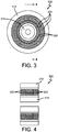
- FIGS. 3-4 show an example tire 300 in accordance with the present invention.
- the tire 300 includes a circular tread band 310, a circular hub 315 for attachment to an axle (not shown), and a structure including a plurality of annular rings 320 interconnecting the tread band 310 and the hub 315 and transferring a load from the tread band to the hub.
- the rings 320 are preferably interconnected by annular bands 330 constructed of materials such as rubber, plastic, metal, and/or other suitable material.
- the annular rings 320 preferably include several rings disposed axially adjacent each other (three in FIG. 4 ) as well as several concentric rings disposed radially adjacent each other (three in FIGS. 3-4 ).
- These rings 320 may include layers of fabric. Some layers may have reinforcement members (such as yarns, filaments, fibers, and/or fabric) which extend in a first and a second direction. Other layers may be connected together by reinforcement members (yarns, filaments, fibers, and/or fabric) or other knitted layers extending in a defined third direction.
- An "open” layer may include individual pile fibers or reinforcements connecting a first and a second layer of fabric.
- a "closed” layer may include fabric piles connecting a first layer and a second layer.
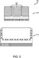
- FIG. 5 shows an example assembly step 500 in accordance with the present invention.
- a tire casing 510 preferable includes a plurality of annular rings 520 (three in FIG. 5 ) that may or may not be similar to the rings 120, 320 of FIGS. 1-4 .
- the annular rings 520 may have identical or different constructions, as desired.
- the rings 520 together define a cartridge 530 for replacement in the corresponding casing 510.
- FIGS. 6-7 show an example tire 600 in accordance with the present invention.
- the tire 600 includes a circular tread band 610, a circular hub 615 for attachment to an axle (not shown), and a structure including a plurality of radially extending twisted spokes 620 interconnecting the tread band 610 and the hub 615 and transferring a load from the tread band to the hub.
- the spokes 620 may be constructed of materials such as rubber, plastic, metal, and/or other suitable material.
- the annular rings 320 may include several spokes disposed axially adjacent each other (three in FIG. 7 ).
- the rings 120, 320 and spokes 620 preferably include layers of fabric. Some layers may have reinforcement members (such as yarns, filaments, fibers, and/or fabric) which extend in a first and a second direction. Other layers may be connected together by reinforcement members (yarns, filaments, fibers, and/or fabric) or other knitted layers extending in a defined third direction.
- An "open” layer may include individual pile fibers or reinforcements connecting a first and a second layer of fabric.
- a "closed” layer may include fabric piles connecting a first layer and a second layer.
- the hub 115, 315, 615 may be metal, polymer and/or carbon material.
- Each ring 120, 320 and/or spoke 620 may be coated/dipped in a dedicated solution for increasing rigidity and strength.
- successive concentric rings 120, 320 of decreasing radius are joined together, preferably by a flexible polymer adhesive layer with or without radial reinforcement.
- the fabric may be constructed of polyester-terephthalate (polyethylene-terehthalate), high performance fibers, etc. These fibers may be constructed as a single component, from such materials as nylon fiber, rayon fiber, polyester fiber, carbon fiber, glass fiber, basalt fiber, polyethylene fiber, aramid fiber, and/or other suitable high performance fibers or of multi component fibers consisting of a combination of these materials.
- the light weight and enhanced mechanical properties of these fibers may allow for many design improvements effecting cost, weight, rolling resistance, etc.
- Thickness of deck layers e.g., shear bands of a non-pneumatic tire
- roll width, density, and height of vertical piles may be adjusted to meet various tire requirements.
- the cells between two deck layers may be filled with light weight material, wires, tubes, foam, sealant material, sensors, etc.
- the materials and material properties of textile reinforced composite structures 120, 320, 620 may be specially customized for particular load situations by modifying the fiber material and/or architecture.
- one five centimeter cube 400 of a three dimensional fabric may weigh only 6.5 grams ( FIG. 8 ).
- the cube 800 may have a plurality of open cells 810 defined by the three-dimensional structure of the fabric 820.
- Another example structure 900 may be five centimeters by five centimeters by 0.7 centimeters and weigh 1.1 grams ( Fig. 9 ).
- a conventional chipper compound of the same dimensions may weigh 30.0 grams.
- the structure 900 may have a plurality of open cells 910 defined by the three-dimensional structure of the fabric 920.
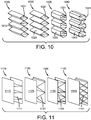
- Fig. 10 shows four example hexagonal constructions 1010, 1020, 1030, 1040 that may be used as rings 120, 320 and/or spokes 620 in a non-pneumatic tire 100, 300, 600.
- the constructions 1010, 1020, 1030, 1040 may have a plurality of closed cells 1011, 1021, 1031, 1041 defined by the three-dimensional structure of the fabric 1013, 1023, 1033, 1043.
- Fig. 11 shows four examples three plane constructions 1110, 1120, 1130, 1140 that may be used as rings 120, 320 and/or spokes 620 in a non-pneumatic tire 100, 300, 600.
- the constructions 1110, 1120, 1130, 1140 may have a plurality of closed cells 1111, 1121, 1131, 1141 defined by the three-dimensional structure of the fabric 1113, 1123, 1133, 1143.
- Fig. 12 shows four example two plane constructions 1210, 1220, 1230, 1240 that may be used as rings 120, 320 and/or 620 in a non-pneumatic tire 100, 300, 600.
- the constructions 1210, 1220, 1230, 1240 may have a plurality of closed cells 1211, 1221, 1231, 1241 defined by the three-dimensional structure of the fabric 1213, 1223, 1233, 1243.
- Fig. 13 shows three example curved constructions 1310, 1320, 1330 that may be used as rings 120, 320 and/or spokes 620 in a non-pneumatic tire 100, 300, 600.
- the constructions 1310, 1320, 1330 may have a plurality of closed cells 1311, 1321, 1331 defined by the three-dimensional structure of the fabric 1313, 1323, 1333.
- Fig. 14 shows an enhanced view of an example construction 1400 detailing the interrelationships of individual fibers 1401 for use as rings 120, 320 and/or spokes 620 in a non-pneumatic tire 100, 300, 600.
- the construction 1400 may have a plurality of open cells 1411 defined by the three-dimensional structure of the fabric 1401.
Landscapes
- Engineering & Computer Science (AREA)
- Mechanical Engineering (AREA)
- Tires In General (AREA)
Abstract
A tire (300) comprising a circular tread band (310), a circular hub (315) for attachment to an axle and a structure located radially between the tread band (310) and the hub (315), wherein the structure includes a plurality of annular rings (320) which respectively interconnect the tread band (310) and the hub (315) and are configured to transfer a load from the tread band (310) to the hub (315), and the plurality of annular rings (320) comprises a first group of rings being disposed axially adjacent each other and a second group of rings being concentric and disposed radially adjacent each other.
Description
- The present invention relates to a tire, and more particularly, to a radial passenger tire or a high performance tire having a three dimensional spacer component. It provides a structurally supported tire as a lightweight tire.
- The pneumatic tire has been the solution of choice for vehicular mobility for over a century. Modern belted, radial carcass, pneumatic tires are remarkable products that provide an effective means for supporting applied loads while allowing reasonable vertical and lateral compliance. The pneumatic tire obtains its mechanical attributes largely due to the action of internal air pressure in the tire cavity. Reaction to the inflation pressure corrects rigidities to the belt and carcass components. Inflation pressure is then one of the most important design parameters for a pneumatic tire.
- Good pressure maintenance is required to obtain the best performance from a pneumatic tire. Inflation pressure below that specified can result in a loss of fuel economy. Of primary importance is that a conventional pneumatic tire is capable of very limited use after a complete loss of inflation pressure. Many tire constructions have been proposed for continued mobility of a vehicle after a complete loss of air pressure from the tire. Commercially available runflat tire solutions are pneumatic tires having added sidewall reinforcements or fillers to permit the sidewalls to act in compression as load supporting members during deflated operation. This added reinforcement often results in the disadvantages of higher tire mass and reduced riding comfort. Other attempts to provide runflat capability utilize essentially annular reinforcing bands in the tire crown portion. In these solutions, the rigidity of the tread portion results partly from the inherent properties of the annular reinforcing band and partly from the reaction to inflation pressure. Still other solutions rely on secondary internal support structures attached to the wheel. These supports add mass to the mounted assembly and either increase mounting difficulty or may require the use of multiple piece rims. All of these approaches are hybrids of an otherwise pneumatic tire structure and suffer from design compromises that are optimal for neither the inflated nor deflated states. In addition, these runflat solutions require the use of some means to monitor tire inflation pressure and to inform the vehicle operator if the inflation pressure is outside the recommended limits.
- A tire designed to operate without inflation pressure may eliminate many of the problems and compromises associated with a pneumatic tire. Neither pressure maintenance nor pressure monitoring is required. Structurally supported tires such as solid tires or other elastomeric structures to date have not provided the levels of performance required from a conventional pneumatic tire. A structurally supported tire solution that delivers pneumatic tire-like performance would be a desirous improvement.
- The invention relates to a tire in accordance with claim 1.
- Dependent claims refer to preferred embodiments of the invention.
- A first tire in accordance with the present invention has an axis of rotation. The first tire includes a circular tread band, a circular hub for attachment to an axle, and a structure including a plurality of annular rings interconnecting the tread band and the hub and transferring a load from the tread band to the hub. A first group of rings are disposed axially adjacent each other and a second group of rings are concentric and disposed radially adjacent each other.
- According to a preferred aspect of the invention, the rings of the plurality of rings include layers of fabric.
- According to another preferred aspect of the invention, the rings of the plurality of rings include reinforcement members of yarn, filaments, fibers, and/or fabric.
- According to another preferred aspect of the invention, the rings of the plurality of rings include layers connected together by reinforcement members.
- According to another preferred aspect of the invention, the rings of the plurality of rings include knitted layers.
- According to another preferred aspect of the invention, the rings of the plurality of rings include an "open" layer of individual pile fibers connecting a first layer of fabric and a second layer of fabric.
- According to another preferred aspect of the invention, the rings of the plurality of rings include a "closed" layer of fabric piles connecting a first layer and a second layer.
- According to another preferred aspect of the invention, the plurality of rings are interconnected by annular bands.
- According to another preferred aspect of the invention, the annular bands are constructed or rubber, of plastic or of metal.
- A second tire in accordance with the present invention has an axis of rotation. The second tire includes a circular tread band, a circular hub for attachment to an axle, and a structure including a plurality of spokes interconnecting the tread band and the hub and transferring a load from the tread band to the hub, the structure having a group of radially extending spokes disposed axially adjacent each other.
- According to a preferred aspect of the invention, the spokes include layers of twisted fabric.
- According to another preferred aspect of the invention, the spokes include reinforcement members of yarn, filaments, fibers, and/or fabric.
- According to another preferred aspect of the invention, the spokes include layers connected together by reinforcement members.
- According to another preferred aspect of the invention, the spokes include knitted layers.
- According to another preferred aspect of the invention, the spokes include an "open" layer of individual pile fibers connecting a first layer of fabric and a second layer of fabric.
- According to another preferred aspect of the invention, the spokes include a "closed" layer of fabric piles connecting a first layer and a second layer.
- "Axial" and "Axially" mean the lines or directions that are parallel to the axis of rotation of the tire.
- "Carcass" means the tire structure apart from the belt structure, tread, undertread over the plies, but including the beads.
- "Casing" means the carcass, belt structure, beads, sidewalls and all other components of the tire excepting the tread and undertread, i.e., the whole tire.
- "Circumferential" most often means circular lines or directions extending along the perimeter of the surface of the annular tread perpendicular to the axial direction; it can also refer to the direction of the sets of adjacent circular curves whose radii define the axial curvature of the tread, as viewed in cross section.
- "Knitted" means a structure producible by interlocking a series of loops of one or more yarns by means of needles or wires, such as warp knits and weft knits.
- "Lateral" means a direction parallel to the axial direction.
- "Radial" and "radially" mean directions radially toward or away from the axis of rotation of the tire.
- "Three dimensional spacer structure" may mean a three dimensional structure composed from two outer layers of fabric, each outer layer of fabric having reinforcement members (such as yarns, filaments, fibers, and/or fabric) which extend in a first and a second direction, the two outer layers connected together by reinforcement members (yarns, filaments, fibers, and/or fabric) or other knitted layers extending in a defined third direction. An "open" three dimensional spacer structure comprises individual pile fibers or reinforcements connecting the first and the second layer of fabric. A "closed" three dimensional structure utilizes fabric piles that connect the first and the second layers.
- "Tread band" means an annular structure that may include a shear band, a tread band, and/or a belt structure.
- The structure, operation, and advantages of the invention will become more apparent upon contemplation of the following description taken in conjunction with the accompanying drawings, wherein:
-
FIG. 1 represents a schematic cross-sectional view of an example tire in accordance with the present invention; -
FIG. 2 represents a schematic sectional view taken along line '2-2' inFIG. 1 ; -
FIG. 3 represents a schematic cross-sectional view of another example tire in accordance with the present invention; -
FIG. 4 represents a schematic sectional view taken along line '4-4' inFIG. 3 ; -
FIG. 5 represents a schematic detail of an assembly step in accordance with the present invention; -
FIG. 6 represents a schematic cross-sectional view of still another example tire in accordance with the present invention; -
FIG. 7 represents a schematic sectional view taken along line '7-7' inFIG. 6 ; -
FIG. 8 represents a schematic detail of an example three-dimensional fabric for use with the present invention; -
FIG. 9 represents a schematic detail of another example three-dimensional fabric in accordance with the present invention; -
FIG. 10 represents a schematic detail of still another example three-dimensional fabric in accordance with the present invention; -
FIG. 11 represents a schematic detail of yet another example three-dimensional fabric in accordance with the present invention; -
FIG. 12 represents a schematic detail of still another example three-dimensional fabric in accordance with the present invention; -
FIG. 13 represents a schematic detail of yet another example three-dimensional fabric in accordance with the present invention; and -
FIG. 14 represents a schematic detail of still another example three-dimensional fabric in accordance with the present invention. - Three dimensional fabric may provide large design freedom for different lightweight pneumatic and non-pneumatic tire components and designs. Three dimensional fabric may be tuned to yield varied mechanical, thermal, and/or electrical properties. Three dimensional fabric may further efficiently distribute stress from one direction to others directions.
-
FIGS. 1-2 show anexample tire 100 in accordance with the present invention. Thetire 100 includes acircular tread band 110, acircular hub 115 for attachment to an axle (not shown), and a structure including a plurality ofannular rings 120 interconnecting thetread band 110 and thehub 115 and transferring a load from the tread band to the hub. The annular rings 120 preferably include several rings disposed axially adjacent each other (three inFIG. 2 ) as well as several concentric rings disposed radially adjacent each other (three inFIGS. 1-2 ). - These
rings 120 preferably include layers of fabric. Some layers may have reinforcement members (such as yarns, filaments, fibers, and/or fabric) which extend in a first and a second direction. Other layers may be connected together by reinforcement members (yarns, filaments, fibers, and/or fabric) or other knitted layers extending in a defined third direction. An "open" layer may include individual pile fibers or reinforcements connecting a first and a second layer of fabric. A "closed" layer may include fabric piles connecting a first layer and a second layer. -
FIGS. 3-4 show anexample tire 300 in accordance with the present invention. Thetire 300 includes acircular tread band 310, acircular hub 315 for attachment to an axle (not shown), and a structure including a plurality ofannular rings 320 interconnecting thetread band 310 and thehub 315 and transferring a load from the tread band to the hub. Therings 320 are preferably interconnected byannular bands 330 constructed of materials such as rubber, plastic, metal, and/or other suitable material. The annular rings 320 preferably include several rings disposed axially adjacent each other (three inFIG. 4 ) as well as several concentric rings disposed radially adjacent each other (three inFIGS. 3-4 ). - These
rings 320 may include layers of fabric. Some layers may have reinforcement members (such as yarns, filaments, fibers, and/or fabric) which extend in a first and a second direction. Other layers may be connected together by reinforcement members (yarns, filaments, fibers, and/or fabric) or other knitted layers extending in a defined third direction. An "open" layer may include individual pile fibers or reinforcements connecting a first and a second layer of fabric. A "closed" layer may include fabric piles connecting a first layer and a second layer. -
FIG. 5 shows anexample assembly step 500 in accordance with the present invention. Atire casing 510 preferable includes a plurality of annular rings 520 (three inFIG. 5 ) that may or may not be similar to therings FIGS. 1-4 . The annular rings 520 may have identical or different constructions, as desired. Preferably, therings 520 together define acartridge 530 for replacement in thecorresponding casing 510. -
FIGS. 6-7 show anexample tire 600 in accordance with the present invention. Thetire 600 includes acircular tread band 610, acircular hub 615 for attachment to an axle (not shown), and a structure including a plurality of radially extendingtwisted spokes 620 interconnecting thetread band 610 and thehub 615 and transferring a load from the tread band to the hub. Thespokes 620 may be constructed of materials such as rubber, plastic, metal, and/or other suitable material. The annular rings 320 may include several spokes disposed axially adjacent each other (three inFIG. 7 ). - The
rings spokes 620 preferably include layers of fabric. Some layers may have reinforcement members (such as yarns, filaments, fibers, and/or fabric) which extend in a first and a second direction. Other layers may be connected together by reinforcement members (yarns, filaments, fibers, and/or fabric) or other knitted layers extending in a defined third direction. An "open" layer may include individual pile fibers or reinforcements connecting a first and a second layer of fabric. A "closed" layer may include fabric piles connecting a first layer and a second layer. - The
hub ring - Preferably, successive
concentric rings - The fabric may be constructed of polyester-terephthalate (polyethylene-terehthalate), high performance fibers, etc. These fibers may be constructed as a single component, from such materials as nylon fiber, rayon fiber, polyester fiber, carbon fiber, glass fiber, basalt fiber, polyethylene fiber, aramid fiber, and/or other suitable high performance fibers or of multi component fibers consisting of a combination of these materials. The light weight and enhanced mechanical properties of these fibers may allow for many design improvements effecting cost, weight, rolling resistance, etc. Thickness of deck layers (e.g., shear bands of a non-pneumatic tire), roll width, density, and height of vertical piles may be adjusted to meet various tire requirements. The cells between two deck layers may be filled with light weight material, wires, tubes, foam, sealant material, sensors, etc.
- The materials and material properties of textile reinforced
composite structures FIG. 8 ). Thecube 800 may have a plurality ofopen cells 810 defined by the three-dimensional structure of thefabric 820. Anotherexample structure 900 may be five centimeters by five centimeters by 0.7 centimeters and weigh 1.1 grams (Fig. 9 ). A conventional chipper compound of the same dimensions may weigh 30.0 grams. Thestructure 900 may have a plurality ofopen cells 910 defined by the three-dimensional structure of thefabric 920. -
Fig. 10 shows four examplehexagonal constructions rings spokes 620 in anon-pneumatic tire constructions closed cells fabric -
Fig. 11 shows four examples threeplane constructions rings spokes 620 in anon-pneumatic tire constructions closed cells fabric -
Fig. 12 shows four example twoplane constructions rings non-pneumatic tire constructions closed cells fabric -
Fig. 13 shows three example curvedconstructions rings spokes 620 in anon-pneumatic tire constructions closed cells fabric -
Fig. 14 shows an enhanced view of anexample construction 1400 detailing the interrelationships ofindividual fibers 1401 for use asrings spokes 620 in anon-pneumatic tire construction 1400 may have a plurality ofopen cells 1411 defined by the three-dimensional structure of thefabric 1401.
Claims (15)
- A tire having an axis of rotation, the tire (300, 600) comprising a circular tread band (310, 610), a circular hub (315, 615) for attachment to an axle and a structure located radially between the tread band (310, 610) and the hub (315, 615), the structure including a plurality of annular rings (320) and/or a plurality of spokes (620), wherein the rings (320) or spokes (620) respectively interconnect the tread band (300, 600) and the hub (315, 615) and are configured to transfer a load from the tread band (310, 610) to the hub (315, 615), and wherein (i) the plurality of rings (320) comprises a first group of rings being disposed axially adjacent each other and a second group of rings being concentric and disposed radially adjacent each other; and/or (ii) the plurality of spokes (620) comprises a group of radially extending spokes disposed axially adjacent each other.
- The tire as set forth in claim 1 wherein the rings (320) of the plurality of rings include reinforcement members of yarn, filaments, fibers, and/or fabric; or wherein the rings (320) include layers of fabric.
- The tire as set forth in claim 1 or 2 wherein the rings (320) of the plurality of rings include layers connected together by reinforcement members.
- The tire as set forth in at least one of the previous claims wherein the rings (320) of the plurality of rings include knitted layers.
- The tire as set forth in at least one of the previous claims wherein the rings (320) of the plurality of rings include a layer of individual pile fibers connecting a first layer of fabric and a second layer of fabric.
- The tire as set forth in at least one of the previous claims wherein the rings (320) of the plurality of rings include a layer of fabric piles connecting a first layer and a second layer.
- The tire as set forth in at least one of the previous claims wherein the plurality of rings (320) are interconnected by annular bands.
- The tire as set forth in claim 7 wherein the annular bands are constructed of rubber, of plastic or of metal.
- The tire as set forth in at least one of the previous claims wherein the first group of rings comprises from 2-20 or from 3 to 10 axially adjacent distinct rings and/or wherein the second group of rings comprises 2 to 10 or from 2 to 5 concentric and radially adjacent distinct rings.
- The tire as set forth in at least one of the previous claims wherein the spokes (620) include layers of twisted fabric; or wherein the spokes (620) include reinforcement members of yarn, filaments, fibers, and/or fabric.
- The tire as set forth in at least one of the previous claims wherein the spokes (620) include layers connected together by reinforcement members.
- The tire as set forth in at least one of the previous claims wherein the spokes (620) include knitted layers.
- The tire as set forth in at least one of the previous claims wherein the spokes (620) include a layer of individual pile fibers connecting a first layer of fabric and a second layer of fabric.
- The tire as set forth in at least one of the previous claims wherein the spokes (620) include a layer of fabric piles connecting a first layer and a second layer.
- The tire as set forth in at least one of the previous claims wherein the tire (300, 600) is a non-pneumatic tire.
Applications Claiming Priority (1)
| Application Number | Priority Date | Filing Date | Title |
|---|---|---|---|
| US15/366,075 US20180154694A1 (en) | 2016-12-01 | 2016-12-01 | Lightweight tire assembly |
Publications (1)
| Publication Number | Publication Date |
|---|---|
| EP3330100A1 true EP3330100A1 (en) | 2018-06-06 |
Family
ID=60515201
Family Applications (1)
| Application Number | Title | Priority Date | Filing Date |
|---|---|---|---|
| EP17204386.1A Withdrawn EP3330100A1 (en) | 2016-12-01 | 2017-11-29 | Structurally supported tire |
Country Status (4)
| Country | Link |
|---|---|
| US (1) | US20180154694A1 (en) |
| EP (1) | EP3330100A1 (en) |
| JP (1) | JP2018090241A (en) |
| CN (1) | CN108128099A (en) |
Families Citing this family (11)
| Publication number | Priority date | Publication date | Assignee | Title |
|---|---|---|---|---|
| FR3045462B1 (en) | 2015-12-17 | 2017-12-29 | Michelin & Cie | PNEUMATIC ASSEMBLY COMPRISING IMPREGNATED FABRIC (S) OR KNIT (S) AND MEANS FOR SACRIFICIAL MAINTENANCE |
| FR3045463B1 (en) * | 2015-12-17 | 2017-12-29 | Michelin & Cie | PNEUMATIC ASSEMBLY COMPRISING FABRIC (S) OR KNIT (S) COMPRISING PRE-ENCOLATED WIRED ELEMENTS |
| FR3061674A1 (en) * | 2017-01-12 | 2018-07-13 | Compagnie Generale Des Etablissements Michelin | ASSEMBLY COMPRISING PARTIALLY BREAKABLE FABRIC AND CARRIER STRUCTURE |
| FR3061675A1 (en) * | 2017-01-12 | 2018-07-13 | Compagnie Generale Des Etablissements Michelin | ASSEMBLY COMPRISING A ROMPABLE STRUCTURE AND A CARRIER STRUCTURE |
| US11518158B2 (en) * | 2017-10-18 | 2022-12-06 | Compagnie Generale Des Etablissements Michelin | Method for manufacturing a sub-assembly for a tire comprising a three-dimensional fabric or knitted material and using a securing element |
| EP3902689B1 (en) * | 2018-12-28 | 2024-02-21 | Bridgestone Americas Tire Operations, LLC | Flexible metallic web elements for non-pneumatic tire |
| US20210170795A1 (en) * | 2019-12-10 | 2021-06-10 | The Goodyear Tire & Rubber Company | Shear band |
| US11511566B2 (en) | 2019-12-10 | 2022-11-29 | The Goodyear Tire & Rubber Company | Shear band |
| US20210300120A1 (en) * | 2020-03-30 | 2021-09-30 | The Goodyear Tire & Rubber Company | Shear band |
| US12065003B2 (en) | 2021-03-29 | 2024-08-20 | The Goodyear Tire & Rubber Company | Shear band construction |
| US20250091387A1 (en) * | 2023-09-18 | 2025-03-20 | The Goodyear Tire & Rubber Company | Non-pneumatic tire |
Citations (5)
| Publication number | Priority date | Publication date | Assignee | Title |
|---|---|---|---|---|
| US20110168313A1 (en) * | 2008-11-10 | 2011-07-14 | Zheng-Dong Ma | Ultralightweight runflat tires based upon negative poisson ratio (npr) auxetic structures |
| US20150174954A1 (en) * | 2013-12-24 | 2015-06-25 | Bridgestone Americas Tire Operations, Llc | Airless tire construction having variable stiffness |
| WO2016089480A1 (en) * | 2014-12-03 | 2016-06-09 | Bridgestone Americas Tire Operations, Llc | Non-pneumatic tire |
| WO2016109702A1 (en) * | 2014-12-31 | 2016-07-07 | Compagnie Generale Des Etablissements Michelin | Cross spoke non-pneumatic tire |
| EP3231636A1 (en) * | 2016-04-13 | 2017-10-18 | The Goodyear Tire & Rubber Company | Non-pneumatic tire |
Family Cites Families (5)
| Publication number | Priority date | Publication date | Assignee | Title |
|---|---|---|---|---|
| US2882950A (en) * | 1956-03-01 | 1959-04-21 | William G Grove | Vehicle tire |
| CN2302910Y (en) * | 1997-06-05 | 1999-01-06 | 宋河金 | Resilient composite hollow non-inflatable inner tube |
| CN2794895Y (en) * | 2005-03-25 | 2006-07-12 | 牛赡光 | Inflation-free tire |
| US8555941B2 (en) * | 2010-08-12 | 2013-10-15 | The Boeing Company | Non-pneumatic survivable tire, cover and fabrication processes |
| KR101796231B1 (en) * | 2016-07-29 | 2017-12-01 | 금호타이어 주식회사 | Non pneumatic tire |
-
2016
- 2016-12-01 US US15/366,075 patent/US20180154694A1/en not_active Abandoned
-
2017
- 2017-11-28 JP JP2017227556A patent/JP2018090241A/en active Pending
- 2017-11-29 EP EP17204386.1A patent/EP3330100A1/en not_active Withdrawn
- 2017-12-01 CN CN201711248333.6A patent/CN108128099A/en active Pending
Patent Citations (5)
| Publication number | Priority date | Publication date | Assignee | Title |
|---|---|---|---|---|
| US20110168313A1 (en) * | 2008-11-10 | 2011-07-14 | Zheng-Dong Ma | Ultralightweight runflat tires based upon negative poisson ratio (npr) auxetic structures |
| US20150174954A1 (en) * | 2013-12-24 | 2015-06-25 | Bridgestone Americas Tire Operations, Llc | Airless tire construction having variable stiffness |
| WO2016089480A1 (en) * | 2014-12-03 | 2016-06-09 | Bridgestone Americas Tire Operations, Llc | Non-pneumatic tire |
| WO2016109702A1 (en) * | 2014-12-31 | 2016-07-07 | Compagnie Generale Des Etablissements Michelin | Cross spoke non-pneumatic tire |
| EP3231636A1 (en) * | 2016-04-13 | 2017-10-18 | The Goodyear Tire & Rubber Company | Non-pneumatic tire |
Also Published As
| Publication number | Publication date |
|---|---|
| JP2018090241A (en) | 2018-06-14 |
| US20180154694A1 (en) | 2018-06-07 |
| CN108128099A (en) | 2018-06-08 |
Similar Documents
| Publication | Publication Date | Title |
|---|---|---|
| US20180154694A1 (en) | Lightweight tire assembly | |
| JP6542100B2 (en) | Pneumatic tire with three-dimensional parts | |
| US20220063353A1 (en) | Tire for vehicle comprising a stiffening structure | |
| US10071603B2 (en) | Lightweight tire | |
| CN108068549B (en) | Non-inflatable support structure | |
| US7926533B2 (en) | Pneumatic tire with increased lower sidewall durability | |
| EP3231635A1 (en) | Shear band and non-pneumatic tire | |
| US5535800A (en) | Pneumatic tire for extended mobility featuring composite ribs | |
| EP3558694B1 (en) | Non-pneumatic wheel and hub | |
| JP2018083620A (en) | Shear band for structurally supported tire | |
| KR20170117337A (en) | Non-pneumatic tire | |
| JP2017197176A (en) | Lightweight tire | |
| EP1094956B1 (en) | Runflat tire having a fabric underlay for improving tread circumferential and meridional rigidity and method of constructing | |
| EP4177078B1 (en) | Non-pneumatic tire and wheel assembly and method of manufacturing | |
| EP3075570B1 (en) | A crown reinforcement for a pneumatic tire | |
| US11697307B2 (en) | Wheel for a support structure | |
| JP6435835B2 (en) | Assembly tire | |
| WO2000020236A1 (en) | Improved construction for runflat tire | |
| EP3176005A1 (en) | A bidirectional monobelt construction for a pneumatic tire | |
| US11975574B2 (en) | Tire/wheel assembly for a support structure | |
| US11794513B2 (en) | Wheel for a support structure | |
| EP4177077B1 (en) | Non-pneumatic tire and wheel assembly and method of manufacturing |
Legal Events
| Date | Code | Title | Description |
|---|---|---|---|
| PUAI | Public reference made under article 153(3) epc to a published international application that has entered the european phase |
Free format text: ORIGINAL CODE: 0009012 |
|
| AK | Designated contracting states |
Kind code of ref document: A1 Designated state(s): AL AT BE BG CH CY CZ DE DK EE ES FI FR GB GR HR HU IE IS IT LI LT LU LV MC MK MT NL NO PL PT RO RS SE SI SK SM TR |
|
| AX | Request for extension of the european patent |
Extension state: BA ME |
|
| STAA | Information on the status of an ep patent application or granted ep patent |
Free format text: STATUS: THE APPLICATION IS DEEMED TO BE WITHDRAWN |
|
| 18D | Application deemed to be withdrawn |
Effective date: 20181207 |