EP3330053B1 - Configurable cooling assembly and cooling method - Google Patents
Configurable cooling assembly and cooling method Download PDFInfo
- Publication number
- EP3330053B1 EP3330053B1 EP17199095.5A EP17199095A EP3330053B1 EP 3330053 B1 EP3330053 B1 EP 3330053B1 EP 17199095 A EP17199095 A EP 17199095A EP 3330053 B1 EP3330053 B1 EP 3330053B1
- Authority
- EP
- European Patent Office
- Prior art keywords
- cooling blocks
- cooling
- assembly
- blocks
- skin
- Prior art date
- Legal status (The legal status is an assumption and is not a legal conclusion. Google has not performed a legal analysis and makes no representation as to the accuracy of the status listed.)
- Active
Links
Images



Classifications
-
- B—PERFORMING OPERATIONS; TRANSPORTING
- B29—WORKING OF PLASTICS; WORKING OF SUBSTANCES IN A PLASTIC STATE IN GENERAL
- B29C—SHAPING OR JOINING OF PLASTICS; SHAPING OF MATERIAL IN A PLASTIC STATE, NOT OTHERWISE PROVIDED FOR; AFTER-TREATMENT OF THE SHAPED PRODUCTS, e.g. REPAIRING
- B29C73/00—Repairing of articles made from plastics or substances in a plastic state, e.g. of articles shaped or produced by using techniques covered by this subclass or subclass B29D
- B29C73/04—Repairing of articles made from plastics or substances in a plastic state, e.g. of articles shaped or produced by using techniques covered by this subclass or subclass B29D using preformed elements
- B29C73/10—Repairing of articles made from plastics or substances in a plastic state, e.g. of articles shaped or produced by using techniques covered by this subclass or subclass B29D using preformed elements using patches sealing on the surface of the article
- B29C73/12—Apparatus therefor, e.g. for applying
-
- B—PERFORMING OPERATIONS; TRANSPORTING
- B64—AIRCRAFT; AVIATION; COSMONAUTICS
- B64F—GROUND OR AIRCRAFT-CARRIER-DECK INSTALLATIONS SPECIALLY ADAPTED FOR USE IN CONNECTION WITH AIRCRAFT; DESIGNING, MANUFACTURING, ASSEMBLING, CLEANING, MAINTAINING OR REPAIRING AIRCRAFT, NOT OTHERWISE PROVIDED FOR; HANDLING, TRANSPORTING, TESTING OR INSPECTING AIRCRAFT COMPONENTS, NOT OTHERWISE PROVIDED FOR
- B64F5/00—Designing, manufacturing, assembling, cleaning, maintaining or repairing aircraft, not otherwise provided for; Handling, transporting, testing or inspecting aircraft components, not otherwise provided for
- B64F5/40—Maintaining or repairing aircraft
-
- B—PERFORMING OPERATIONS; TRANSPORTING
- B29—WORKING OF PLASTICS; WORKING OF SUBSTANCES IN A PLASTIC STATE IN GENERAL
- B29C—SHAPING OR JOINING OF PLASTICS; SHAPING OF MATERIAL IN A PLASTIC STATE, NOT OTHERWISE PROVIDED FOR; AFTER-TREATMENT OF THE SHAPED PRODUCTS, e.g. REPAIRING
- B29C35/00—Heating, cooling or curing, e.g. crosslinking or vulcanising; Apparatus therefor
- B29C35/16—Cooling
-
- B—PERFORMING OPERATIONS; TRANSPORTING
- B29—WORKING OF PLASTICS; WORKING OF SUBSTANCES IN A PLASTIC STATE IN GENERAL
- B29C—SHAPING OR JOINING OF PLASTICS; SHAPING OF MATERIAL IN A PLASTIC STATE, NOT OTHERWISE PROVIDED FOR; AFTER-TREATMENT OF THE SHAPED PRODUCTS, e.g. REPAIRING
- B29C65/00—Joining or sealing of preformed parts, e.g. welding of plastics materials; Apparatus therefor
- B29C65/02—Joining or sealing of preformed parts, e.g. welding of plastics materials; Apparatus therefor by heating, with or without pressure
- B29C65/18—Joining or sealing of preformed parts, e.g. welding of plastics materials; Apparatus therefor by heating, with or without pressure using heated tools
- B29C65/24—Joining or sealing of preformed parts, e.g. welding of plastics materials; Apparatus therefor by heating, with or without pressure using heated tools characterised by the means for heating the tool
- B29C65/242—Joining or sealing of preformed parts, e.g. welding of plastics materials; Apparatus therefor by heating, with or without pressure using heated tools characterised by the means for heating the tool the heat transfer being achieved by contact, i.e. a heated tool being brought into contact with the welding tool and afterwards withdrawn from it
-
- B—PERFORMING OPERATIONS; TRANSPORTING
- B29—WORKING OF PLASTICS; WORKING OF SUBSTANCES IN A PLASTIC STATE IN GENERAL
- B29C—SHAPING OR JOINING OF PLASTICS; SHAPING OF MATERIAL IN A PLASTIC STATE, NOT OTHERWISE PROVIDED FOR; AFTER-TREATMENT OF THE SHAPED PRODUCTS, e.g. REPAIRING
- B29C73/00—Repairing of articles made from plastics or substances in a plastic state, e.g. of articles shaped or produced by using techniques covered by this subclass or subclass B29D
- B29C73/24—Apparatus or accessories not otherwise provided for
-
- B—PERFORMING OPERATIONS; TRANSPORTING
- B32—LAYERED PRODUCTS
- B32B—LAYERED PRODUCTS, i.e. PRODUCTS BUILT-UP OF STRATA OF FLAT OR NON-FLAT, e.g. CELLULAR OR HONEYCOMB, FORM
- B32B27/00—Layered products comprising a layer of synthetic resin
-
- B—PERFORMING OPERATIONS; TRANSPORTING
- B32—LAYERED PRODUCTS
- B32B—LAYERED PRODUCTS, i.e. PRODUCTS BUILT-UP OF STRATA OF FLAT OR NON-FLAT, e.g. CELLULAR OR HONEYCOMB, FORM
- B32B37/00—Methods or apparatus for laminating, e.g. by curing or by ultrasonic bonding
- B32B37/06—Methods or apparatus for laminating, e.g. by curing or by ultrasonic bonding characterised by the heating method
-
- F—MECHANICAL ENGINEERING; LIGHTING; HEATING; WEAPONS; BLASTING
- F28—HEAT EXCHANGE IN GENERAL
- F28F—DETAILS OF HEAT-EXCHANGE AND HEAT-TRANSFER APPARATUS, OF GENERAL APPLICATION
- F28F7/00—Elements not covered by group F28F1/00, F28F3/00 or F28F5/00
- F28F7/02—Blocks traversed by passages for heat-exchange media
-
- B—PERFORMING OPERATIONS; TRANSPORTING
- B29—WORKING OF PLASTICS; WORKING OF SUBSTANCES IN A PLASTIC STATE IN GENERAL
- B29C—SHAPING OR JOINING OF PLASTICS; SHAPING OF MATERIAL IN A PLASTIC STATE, NOT OTHERWISE PROVIDED FOR; AFTER-TREATMENT OF THE SHAPED PRODUCTS, e.g. REPAIRING
- B29C73/00—Repairing of articles made from plastics or substances in a plastic state, e.g. of articles shaped or produced by using techniques covered by this subclass or subclass B29D
- B29C73/24—Apparatus or accessories not otherwise provided for
- B29C73/30—Apparatus or accessories not otherwise provided for for local pressing or local heating
- B29C73/34—Apparatus or accessories not otherwise provided for for local pressing or local heating for local heating
-
- B—PERFORMING OPERATIONS; TRANSPORTING
- B29—WORKING OF PLASTICS; WORKING OF SUBSTANCES IN A PLASTIC STATE IN GENERAL
- B29K—INDEXING SCHEME ASSOCIATED WITH SUBCLASSES B29B, B29C OR B29D, RELATING TO MOULDING MATERIALS OR TO MATERIALS FOR MOULDS, REINFORCEMENTS, FILLERS OR PREFORMED PARTS, e.g. INSERTS
- B29K2101/00—Use of unspecified macromolecular compounds as moulding material
- B29K2101/10—Thermosetting resins
-
- B—PERFORMING OPERATIONS; TRANSPORTING
- B29—WORKING OF PLASTICS; WORKING OF SUBSTANCES IN A PLASTIC STATE IN GENERAL
- B29K—INDEXING SCHEME ASSOCIATED WITH SUBCLASSES B29B, B29C OR B29D, RELATING TO MOULDING MATERIALS OR TO MATERIALS FOR MOULDS, REINFORCEMENTS, FILLERS OR PREFORMED PARTS, e.g. INSERTS
- B29K2105/00—Condition, form or state of moulded material or of the material to be shaped
- B29K2105/24—Condition, form or state of moulded material or of the material to be shaped crosslinked or vulcanised
- B29K2105/246—Uncured, e.g. green
-
- B—PERFORMING OPERATIONS; TRANSPORTING
- B29—WORKING OF PLASTICS; WORKING OF SUBSTANCES IN A PLASTIC STATE IN GENERAL
- B29K—INDEXING SCHEME ASSOCIATED WITH SUBCLASSES B29B, B29C OR B29D, RELATING TO MOULDING MATERIALS OR TO MATERIALS FOR MOULDS, REINFORCEMENTS, FILLERS OR PREFORMED PARTS, e.g. INSERTS
- B29K2105/00—Condition, form or state of moulded material or of the material to be shaped
- B29K2105/25—Solid
- B29K2105/253—Preform
-
- B—PERFORMING OPERATIONS; TRANSPORTING
- B29—WORKING OF PLASTICS; WORKING OF SUBSTANCES IN A PLASTIC STATE IN GENERAL
- B29L—INDEXING SCHEME ASSOCIATED WITH SUBCLASS B29C, RELATING TO PARTICULAR ARTICLES
- B29L2009/00—Layered products
-
- B—PERFORMING OPERATIONS; TRANSPORTING
- B29—WORKING OF PLASTICS; WORKING OF SUBSTANCES IN A PLASTIC STATE IN GENERAL
- B29L—INDEXING SCHEME ASSOCIATED WITH SUBCLASS B29C, RELATING TO PARTICULAR ARTICLES
- B29L2031/00—Other particular articles
- B29L2031/30—Vehicles, e.g. ships or aircraft, or body parts thereof
- B29L2031/3076—Aircrafts
-
- B—PERFORMING OPERATIONS; TRANSPORTING
- B32—LAYERED PRODUCTS
- B32B—LAYERED PRODUCTS, i.e. PRODUCTS BUILT-UP OF STRATA OF FLAT OR NON-FLAT, e.g. CELLULAR OR HONEYCOMB, FORM
- B32B2305/00—Condition, form or state of the layers or laminate
- B32B2305/77—Uncured, e.g. green
-
- B—PERFORMING OPERATIONS; TRANSPORTING
- B32—LAYERED PRODUCTS
- B32B—LAYERED PRODUCTS, i.e. PRODUCTS BUILT-UP OF STRATA OF FLAT OR NON-FLAT, e.g. CELLULAR OR HONEYCOMB, FORM
- B32B2309/00—Parameters for the laminating or treatment process; Apparatus details
- B32B2309/02—Temperature
-
- B—PERFORMING OPERATIONS; TRANSPORTING
- B32—LAYERED PRODUCTS
- B32B—LAYERED PRODUCTS, i.e. PRODUCTS BUILT-UP OF STRATA OF FLAT OR NON-FLAT, e.g. CELLULAR OR HONEYCOMB, FORM
- B32B2398/00—Unspecified macromolecular compounds
- B32B2398/10—Thermosetting resins
-
- B—PERFORMING OPERATIONS; TRANSPORTING
- B32—LAYERED PRODUCTS
- B32B—LAYERED PRODUCTS, i.e. PRODUCTS BUILT-UP OF STRATA OF FLAT OR NON-FLAT, e.g. CELLULAR OR HONEYCOMB, FORM
- B32B2605/00—Vehicles
- B32B2605/18—Aircraft
Definitions
- the present disclosure generally relates to an apparatus according to claim 1 and to a method according to claim 10 for cooling structures, and deals more particularly with an array of configurable cooling blocks for conducting heat away from a structure.
- HSM heat sensitive materials
- chilled air and/or fans can be used to cool the skin between the edge of the heating blanket and the HSM, in order to prevent overheating of the HSM.
- the distance between the edge of the heating blanket and the HSM may be relatively small, for example on the order of a few inches, limiting the effectiveness of cooling fans.
- the challenge of preventing overheating of HSMs is made more difficult by complicated structural geometries and repair areas that are hard-to-reach.
- Patent document US 2013/0216445 A1 published on 22 August 2013 , in accordance with its abstract states a Fischer Tropsch ("FT") unit including at least one FT reactor tube.
- the FT reactor tube is configured to convert syngas into one or more hydrocarbon products.
- Inside the tube is a nano-sized catalyst particles dispersed in a micro-fibrous substrate.
- the FT reactor tube may be positioned within a cooling block that may be made of aluminum or another metal.
- the cooling block includes an aperture, wherein the FT reactor tube is housed within the aperture.
- At least one cooling channel is located on the cooling block.
- the cooling channel houses at least one cooling tube that is designed to dissipate the heat produced by the FT reaction.
- Patent document US 2015/0366105 A1, published 17 December 2015 in accordance with its abstract states a configurable heat transfer grids that provide cooling to computing components.
- Some embodiments may include a configurable heat transfer grid comprising a cooling frame and one or more cooling elements.
- the cooling frame may define a plurality of receptacles that are each configured to receive one or more cooling elements.
- the one or more cooling elements may include an elongated shape and may be configured to be disposed within one or more of the plurality of receptacles, such as through apertures at outer ends of the cooling frame.
- the cooling elements may include heat pipes and/or heat spreaders.
- Some embodiments may provide for configurable heat transfer grids that include split cooling frames that can be opened for cooling element placement.
- Some embodiments may further provide for configuring a configurable heat transfer grid to implement effective and inexpensive heat removal for a wide range of specific printed circuit board assembly (PCBA) layouts, dimensions, and component types.
- PCBA printed circuit board assembly
- the disclosure relates in general to cooling of structures to prevent overheating of HSMs, and more specifically to a configurable cooling assembly for use in conducting heat away from HSMs in the proximity of a bonded repair.
- an apparatus for cooling a structure, comprising an assembly of configurable, thermally conductive cooling blocks.
- the cooling blocks are configured to be placed against a surface of the structure and fit within a predetermined volume of space adjacent to the structure, wherein the cooling blocks include interconnections coupling the cooling blocks together, wherein the interconnections are releasable to allow the shape of the assembly of the cooling blocks to be reconfigured.
- a method is provided of managing the temperature of heat sensitive materials located near a repair patch being thermally cured on a composite skin using a heating blanket.
- the method comprises configuring an assembly of thermally conductive cooling blocks to fit within a space between the heat blanket and the heat sensitive material, and installing the assembly of thermally conductive cooling blocks against the skin within the space.
- an apparatus being for cooling a structure
- the apparatus comprising: an assembly of configurable, thermally conductive cooling blocks configured to be placed against a surface of the structure and fit within a predetermined volume of space adjacent the structure, wherein the cooling blocks include interconnections coupling the cooling blocks together, wherein the interconnections are releasable to allow the shape of the assembly of the cooling blocks to be reconfigured, wherein the apparatus is used for preventing overheating of heat sensitive materials near a repair patch being thermally cured on a composite skin by a heat source.
- cooling assembly is simple, passive, may be installed in tight spaces and is readily configurable to suit unusual or complex geometries of a structure requiring cooling.
- Another advantage of the cooling assembly is that it is reusable and can be reconfigured to achieve different heat sink shapes and levels of cooling required in different applications.
- a further advantage of the cooling assembly is that it avoids the need for interrupting thermal curing of a composite patch when there is a risk of overheating of the adjacent HSMs.
- Figure 1 illustrates a composite laminate structure such as a composite aircraft skin 20 having an area 22 (hereinafter "repair area”) requiring in-situ repair or rework in order to correct an out-of-specification condition such as impact damage.
- the repair is carried out using a cured or uncured composite laminate patch that is bonded to the skin 20 using a bonding adhesive.
- a curing assembly (not shown) that includes a heating blanket 28, is used to thermally cure the bonding adhesive and/or the repair patch, which is typically comprised of a fiber reinforced, thermoset or a thermoplastic laminate.
- the curing assembly may also include a vacuum bag (not shown) that is used to compact the repair patch during the cure process.
- the repair area 22 is located near a heat sensitive material (HSM) 24 which, in the illustrated example, comprises a structural stiffener 24a having a cap 26 which is bonded or otherwise fixed to the surface 20a of the skin 20.
- HSM heat sensitive material
- the stiffener 24a may comprise a HSM 24 such as, for example and without limitation, a peened titanium or aluminum which may be impacted if heated above a certain temperature.
- the temperature at which the HSM 24 is impacted is less than the cure temperature (in the case of a thermoset patch) or consolidation temperature (in the case of a thermoplastic patch) of the repair patch.
- cure temperature refers to the cure temperature of a composite laminate repair patch formed of a thermosetting polymer resin, a thermoplastic polymer resin, hybrid material systems containing both thermosets and thermoplastics, and bonding adhesives used to bond such patches to an underlying structure such as the skin 20.
- Peened titanium stiffener 24a may be impacted when exposed to temperatures exceeding 93.33 °C (200°F) whereas the heating blanket 28 may generate temperatures well in excess of 93.33 °C (200°F), for example 148.89 °C - 176.67 °C -(300°F - 350°F) for a thermoset repair patch.
- thermal energy generated by the heating blanket 28 is transferred both by conduction 30 through the skin 20 and radiation 32 to the stiffener 24a, thereby raising the temperature of the HSM 24.
- cooling block assembly an assembly 36 of thermally conductive cooling blocks 38 (hereinafter “cooling block assembly”), arranged in a three-dimensional array, is placed against the surface 20a of the skin 20.
- the cooling block assembly 36 is used to manage the temperature of the HSM 24.
- the cooling block assembly 36 is configured to fit within the space 34 ( Figure 1 ) between the edge of the heating blanket 28 and the cap 26 of the stiffener 24a.
- the cooling block assembly 36 comprises a three-dimensional array of individual cooling blocks 38, arranged in five layers on an underlying support 39 that holds the cooling block assembly 36 against the skin surface 20a.
- the support 39 comprises a flat plate driven upwardly by a jack or similar force applicator, forcing the assembly 36 of cooling blocks 38 against the skin surface 20a.
- a variety of other means of supporting the cooling blocks 38 and forcing them against the skin surface 20a are possible, such as straps, scaffolding, etc.
- five layers 44 of cooling blocks 38 are illustrated in Figures 2 and 3 , more than five layers 44 or as few as one layer 44 may be suitable, depending upon the application.
- the layers 44 of cooling blocks 38 are shown as staggered relative to each other in Figures 2 and 3 to increase the exposed surface area of the assembly, they may be vertically aligned so as to form rows and columns.
- the cooling block assembly 36 manages the temperature of the HSM 24 by acting as a heat sink, conducting a portion 46 of the heat out of the skin away from the HSM 24, such that only a residual portion 48 of the heat conducted through the skin 20 reaches the HSM 24.
- the amount of heat that is conducted away from the skin 20 by the cooling block assembly 36 will depend on a number of factors, including but not limited to the number of cooling blocks 38 in contact with the surface 20a of the skin 20, the thermal conductivity of the cooling blocks 38, the collective mass of the cooling blocks 38 and the surface area of the cooling blocks 38 that is exposed to the surrounding environment.
- the cooling block assembly 36 In addition to reducing the heat conducted through the skin 20 to the HSM 24, the cooling block assembly 36 also absorbs heat that is radiated 32 by the heating blanket 28, which would otherwise impact the HSM 24.
- each of the cooling blocks 38 is in the shape of a cube, having a height H, width W, and length L dimensions that are equal. In other examples, however, these dimensions may be unequal.
- each of the cooling blocks 38 maybe elongate, wherein its length L is considerably greater than either its height H or width W.
- the illustrated cooling block 38 is a shape that has flat sides which maximize the surface contact between the cooling blocks 38, other shapes are possible.
- the cooling blocks 38 may be rectangular, cylindrical or pyramidal in shape, to name only a few possibilities.
- the surfaces of the cooling blocks 38 should have smooth surfaces with minimal porosity in order to maximize heat transfer between the interfacial boundaries of adjacent blocks 38.
- the cooling blocks 38 are formed of a material that is relatively high in thermal conductivity and is easily machined, such as, without limitation, copper or aluminum, or an alloy of these two or other thermally conductive materials.
- the thermal conductivity of the cooling blocks 38 should be sufficient to result in minimal residual heat conduction 48 to the HSM 24.
- certain cooling blocks 38 may have one or more through-holes 40 therein, each of which has a suitable diameter.
- the top or first layer 44 of cooling blocks 38 in contact with the skin 20 do not have any through-holes 40, while the cooling blocks 38 in the second and third layers 44 each have a single through-hole 40, and the cooling blocks 38 in the fourth and fifth layers 44 each have four through-holes 40.
- the through-holes 40 increase the exposed surface area of the cooling blocks 38 and therefore increase the amount of heat that is radiated away from the cooling blocks 38 to the surrounding environment.
- cooling blocks 38 closest to the skin 20 that do not have through-holes 40 because the absence of through-holes 40 increases the thermal mass of those cooling blocks 38, allowing them to conduct heat away from the skin 20 more quickly.
- the cooling blocks 38 may be arranged such that the through-holes 40 are aligned to form continuous air passageways 42 through the cooling block assembly 36, allowing passive convection cooling.
- active cooling may be achieved by employing a fan 52 or other forced air source to force air 50 through the passageways 42.
- the air 50 flowing through the passageways 42 draws heat away from the cooling block assembly 36, thereby enhancing its ability to cool the skin 20 and reduce elevation of the temperature of the HSM 24 caused by the heating blanket 28.
- FIG 6 illustrates one arrangement for mechanically interconnecting the cooling blocks 38 using interlocking gibs 54 and ways 56 which allow the cooling blocks 38 to be slidably assembled with each other.
- Figure 7 illustrates another arrangement in which each of the cooling blocks 38 includes one or more recessed magnets 58. The magnets 58 in adjacent cooling blocks 38 are aligned with and attract each other, holding the cooling blocks 38 together in the assembly 36 by magnetic forces.
- Figure 8 illustrates a further arrangement in which pins or releasable snap fit fasteners 60, such as, without limitation, ball and socket connections are used to interconnect the cooling blocks 38. In some applications the fasteners 60 may comprise simple pins. A variety of other techniques can be used to hold the cooling blocks 38 together as an assembly 36, including but not limited to thermally conductive adhesives.
- FIGS 9 and 10 illustrate another example in which an assembly 36 of cooling blocks 38 (only three of which are shown in the Figures) are held against a composite skin 20 using the force of gravity G.
- the bottom 38a of each of the cooling blocks 38 is provided with one or more raised locating balls 64 that are received within corresponding indexing recesses 62 in the top surfaces 38b of an underlying cooling block 38.
- the cooling block assembly 36 may be used to conduct heat away from a curved or contoured composite skin 20.
- one or more layers 44 of cooling blocks 38 are arranged on top of a composite skin 20, positioned within a space 34 between the edge 28a of a heating blanket 28, and an underlying stiffener 24a formed of a HSM 24.
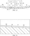
- the composite skin 20 is curved in two dimensions, and the cooling block assembly 36 substantially conforms to the contour of the skin 20.
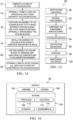
- the bottom 38a of each cooling block 38 is substantially flat, and thus forms a slight gap 68 ( Figure 13 ) between the cooling block 38 and the skin surface 20a.
- a thermally conductive liquid shim 70 may be used to fill the gap 68 in order to prevent or minimize reduction of the heat transferred from the skin 20 to the cooling blocks 38.
- a relatively small, pie-shaped gap 66 may be formed between the walls of adjacent ones of the cooling blocks 38.
- the gaps 66 may be used to allow convective air currents to pass through the cooling block assembly 36, optionally aided by a fan ( Figure 5 ) that forces air through the gap 66.
- the gaps 66 may be filled with the liquid shim 70.
- thermally conductive metal shims (not shown) may be employed to fill either of the gaps 66, 68.
- Figure 14 illustrates a method for cooling a structure such as a skin 20 that includes a heat sensitive material 24.
- a plurality of cooling blocks 38 are fabricated, and optionally at 74, at least one through hole 40 is formed in at least certain of the cooling blocks 38.
- an assembly 36 of the cooling blocks 38 is configured to fit a space 34 between a heating blanket 28 and the heat sensitive material 24.
- the cooling blocks 38 may be interconnected.
- the assembly 36 of the cooling blocks 38 is installed against the composite skin 20 within the space 34 between the heating blanket 28 and the heat sensitive material 24.
- the assembly 36 of cooling blocks 38 is used to transfer heat away from the composite skin 20 to the ambient environment.
- active cooling may be employed, as by using a fan 52 to force air 50 over/through the cooling blocks 38.
- Aircraft applications of the disclosed embodiments may include, for example, without limitation, fuel and hydraulic systems that use tubes containing pressurized fluids.
- exemplary method 84 may include specification and design 88 of the aircraft 86 and material procurement 90.
- component and subassembly manufacturing 92 and system integration 94 of the aircraft 86 takes place.
- the aircraft 86 may go through certification and delivery 96 in order to be placed in service 98. While in service by a customer, the aircraft 86 is scheduled for routine maintenance and service 100, which may also include modification, reconfiguration, refurbishment, and so on.
- Each of the processes of method 84 may be performed or carried out by a system integrator, a third party, and/or an operator (e.g., a customer).
- a system integrator may include without limitation any number of aircraft manufacturers and major-system subcontractors
- a third party may include without limitation any number of vendors, subcontractors, and suppliers
- an operator may be an airline, leasing company, military entity, service organization, and so on.
- the aircraft 86 produced by exemplary method 84 may include an airframe 102 with a plurality of systems 104 and an interior 106.
- the airframe 102 may include heat sensitive materials that must be protected from overheating during for example, thermal curing of composite repairs.
- Examples of high-level systems 104 include one or more of a propulsion system 108, an electrical system 110, a hydraulic system 112 and an environmental system 114. Any number of other systems may be included.
- an aerospace example is shown, the principles of the disclosure may be applied to other industries, such as the marine and automotive industries.
- Systems and methods embodied herein may be employed during any one or more of the stages of the production and service method 84.
- components or subassemblies corresponding to production process 92 may be fabricated or manufactured in a manner similar to components or subassemblies produced while the aircraft 86 is in service.
- one or more apparatus embodiments, method embodiments, or a combination thereof may be utilized during the production stages 92 and 94, for example, by substantially expediting assembly of or reducing the cost of an aircraft 86.
- apparatus embodiments, method embodiments, or a combination thereof may be utilized while the aircraft 86 is in service, for example and without limitation, to maintenance and service 100.
- the phrase "at least one of', when used with a list of items, means different combinations of one or more of the listed items may be used and only one of each item in the list may be needed.
- “at least one of item A, item B, and item C” may include, without limitation, item A, item A and item B, or item B. This example also may include item A, item B, and item C or item B and item C.
- the item may be a particular object, thing, or a category. In other words, at least one of means any combination items and number of items may be used from the list but not all of the items in the list are required.
Landscapes
- Engineering & Computer Science (AREA)
- Mechanical Engineering (AREA)
- Physics & Mathematics (AREA)
- Thermal Sciences (AREA)
- Health & Medical Sciences (AREA)
- Oral & Maxillofacial Surgery (AREA)
- General Engineering & Computer Science (AREA)
- Manufacturing & Machinery (AREA)
- Transportation (AREA)
- Aviation & Aerospace Engineering (AREA)
- Thermotherapy And Cooling Therapy Devices (AREA)
- Cooling Or The Like Of Electrical Apparatus (AREA)
Description
- The present disclosure generally relates to an apparatus according to
claim 1 and to a method according to claim 10 for cooling structures, and deals more particularly with an array of configurable cooling blocks for conducting heat away from a structure. - It is sometimes necessary to protect heat sensitive structures against overheating. For example, in order to carry out an in-situ repair of a composite structure such as a composite aircraft skin, a heating blanket is used to thermally cure a composite repair patch placed on area of the skin requiring repair. In some cases, the skin repair area is located close to heat sensitive materials (HSM) such as an underlying peened titanium or aluminum stiffener.
- Depending on the difficulty of the application, shot bags that act as heat sinks, chilled air and/or fans can be used to cool the skin between the edge of the heating blanket and the HSM, in order to prevent overheating of the HSM. In other applications, however, the distance between the edge of the heating blanket and the HSM may be relatively small, for example on the order of a few inches, limiting the effectiveness of cooling fans. The challenge of preventing overheating of HSMs is made more difficult by complicated structural geometries and repair areas that are hard-to-reach.
- Patent document
US 2013/0216445 A1, published on 22 August 2013 , in accordance with its abstract states a Fischer Tropsch ("FT") unit including at least one FT reactor tube. The FT reactor tube is configured to convert syngas into one or more hydrocarbon products. Inside the tube is a nano-sized catalyst particles dispersed in a micro-fibrous substrate. The FT reactor tube may be positioned within a cooling block that may be made of aluminum or another metal. The cooling block includes an aperture, wherein the FT reactor tube is housed within the aperture. At least one cooling channel is located on the cooling block. The cooling channel houses at least one cooling tube that is designed to dissipate the heat produced by the FT reaction. - Patent document
US 2015/0366105 A1, published 17 December 2015 , in accordance with its abstract states a configurable heat transfer grids that provide cooling to computing components. Some embodiments may include a configurable heat transfer grid comprising a cooling frame and one or more cooling elements. The cooling frame may define a plurality of receptacles that are each configured to receive one or more cooling elements. The one or more cooling elements may include an elongated shape and may be configured to be disposed within one or more of the plurality of receptacles, such as through apertures at outer ends of the cooling frame. The cooling elements may include heat pipes and/or heat spreaders. Some embodiments may provide for configurable heat transfer grids that include split cooling frames that can be opened for cooling element placement. Some embodiments may further provide for configuring a configurable heat transfer grid to implement effective and inexpensive heat removal for a wide range of specific printed circuit board assembly (PCBA) layouts, dimensions, and component types. - The disclosure relates in general to cooling of structures to prevent overheating of HSMs, and more specifically to a configurable cooling assembly for use in conducting heat away from HSMs in the proximity of a bonded repair.
- According to one aspect, an apparatus is provided for cooling a structure, comprising an assembly of configurable, thermally conductive cooling blocks. The cooling blocks are configured to be placed against a surface of the structure and fit within a predetermined volume of space adjacent to the structure, wherein the cooling blocks include interconnections coupling the cooling blocks together, wherein the interconnections are releasable to allow the shape of the assembly of the cooling blocks to be reconfigured.
- According to another aspect, a method is provided of managing the temperature of heat sensitive materials located near a repair patch being thermally cured on a composite skin using a heating blanket. The method comprises configuring an assembly of thermally conductive cooling blocks to fit within a space between the heat blanket and the heat sensitive material, and installing the assembly of thermally conductive cooling blocks against the skin within the space.
- According to still another aspect, use of an apparatus is provided, the apparatus being for cooling a structure, the apparatus comprising: an assembly of configurable, thermally conductive cooling blocks configured to be placed against a surface of the structure and fit within a predetermined volume of space adjacent the structure, wherein the cooling blocks include interconnections coupling the cooling blocks together, wherein the interconnections are releasable to allow the shape of the assembly of the cooling blocks to be reconfigured, wherein the apparatus is used for preventing overheating of heat sensitive materials near a repair patch being thermally cured on a composite skin by a heat source.
- One of the advantages of the cooling assembly is that it is simple, passive, may be installed in tight spaces and is readily configurable to suit unusual or complex geometries of a structure requiring cooling. Another advantage of the cooling assembly is that it is reusable and can be reconfigured to achieve different heat sink shapes and levels of cooling required in different applications. A further advantage of the cooling assembly is that it avoids the need for interrupting thermal curing of a composite patch when there is a risk of overheating of the adjacent HSMs.
- The features, functions, and advantages can be achieved independently in various embodiments of the present disclosure or may be combined in yet other embodiments in which further details can be seen with reference to the following description and drawings.
- The novel features believed characteristic of the illustrative embodiments are set forth in the appended claims. The illustrative embodiments, however, as well as a preferred mode of use, further objectives and advantages thereof, will best be understood by reference to the following detailed description of an illustrative embodiment of the present disclosure when read in conjunction with the accompanying drawings, wherein:
-
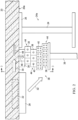
Figure 1 is an illustration of a diagrammatic cross-sectional view of a composite skin in which an HSM is located near an area of skin requiring repair. -
Figure 2 is an illustration similar toFigure 1 but showing installation of a configurable cooling block assembly. -
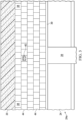
Figure 3 is an illustration of a sectional view taken along the line 3-3 inFigure 2 , wherein one of the cooling blocks is broken away in section to reveal an internal through-hole. -
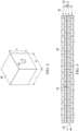
Figure 4 is an illustration of a perspective view of one of the cooling blocks forming part of the configurable cooling block assembly. -
Figure 5 is an illustration of a fragmentary side view of one row of the cooling blocks shown inFigures 2 and3 , wherein the blocks are broken away in section to reveal a continuous air passageway through the row. -
Figure 6 is an illustration of an end view of several of the cooling blocks, showing one form of interconnection between the cooling blocks. -
Figure 7 is an illustration of an end view of several cooling blocks, showing another form of interconnection between the cooling blocks. -
Figure 8 is an illustration of an end view of several cooling blocks, showing a further form of interconnection between the cooling blocks. -
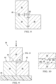
Figure 9 is an illustration of an end view of several the cooling blocks held against an underlying composite skin by the force of gravity. -
Figure 10 is an illustration of the area designated as "FIG. 10 " inFigure 9 . -
Figure 11 is an illustration of a fragmentary, perspective view showing use of the cooling blocks during repair of a composite skin curved in two dimensions. -
Figure 12 is an illustration of an end view of two of the cooling blocks supported on an underlying contoured skin surface. -
Figure 13 is an illustration of the area designated as "FIG. 13 " inFigure 12 . -
Figure 14 is an illustration of a flow diagram of a method for cooling a structure that includes HSMs. -
Figure 15 is an illustration of a flow diagram of aircraft production and service methodology. -
Figure 16 is an illustration of a block diagram of an aircraft. -
Figure 1 illustrates a composite laminate structure such as acomposite aircraft skin 20 having an area 22 (hereinafter "repair area") requiring in-situ repair or rework in order to correct an out-of-specification condition such as impact damage. Although not shown in the Figures, the repair is carried out using a cured or uncured composite laminate patch that is bonded to theskin 20 using a bonding adhesive. A curing assembly (not shown) that includes aheating blanket 28, is used to thermally cure the bonding adhesive and/or the repair patch, which is typically comprised of a fiber reinforced, thermoset or a thermoplastic laminate. The curing assembly may also include a vacuum bag (not shown) that is used to compact the repair patch during the cure process. - The
repair area 22 is located near a heat sensitive material (HSM) 24 which, in the illustrated example, comprises astructural stiffener 24a having acap 26 which is bonded or otherwise fixed to thesurface 20a of theskin 20. A minimal amount ofspace 34 is present between theedge 28a of theheating blanket 28 and the HSM 24. Thestiffener 24a may comprise aHSM 24 such as, for example and without limitation, a peened titanium or aluminum which may be impacted if heated above a certain temperature. The temperature at which theHSM 24 is impacted is less than the cure temperature (in the case of a thermoset patch) or consolidation temperature (in the case of a thermoplastic patch) of the repair patch. For convenience in the remaining description "cure temperature" refers to the cure temperature of a composite laminate repair patch formed of a thermosetting polymer resin, a thermoplastic polymer resin, hybrid material systems containing both thermosets and thermoplastics, and bonding adhesives used to bond such patches to an underlying structure such as theskin 20. Peenedtitanium stiffener 24a may be impacted when exposed to temperatures exceeding 93.33 °C (200°F) whereas theheating blanket 28 may generate temperatures well in excess of 93.33 °C (200°F), for example 148.89 °C - 176.67 °C -(300°F - 350°F) for a thermoset repair patch. During thermal curing of the repair patch, thermal energy generated by theheating blanket 28 is transferred both byconduction 30 through theskin 20 andradiation 32 to thestiffener 24a, thereby raising the temperature of theHSM 24. - Referring now to
Figures 2-4 , anassembly 36 of thermally conductive cooling blocks 38 (hereinafter "cooling block assembly"), arranged in a three-dimensional array, is placed against thesurface 20a of theskin 20. As will be discussed below in more detail, thecooling block assembly 36 is used to manage the temperature of theHSM 24. Thecooling block assembly 36 is configured to fit within the space 34 (Figure 1 ) between the edge of theheating blanket 28 and thecap 26 of thestiffener 24a. In the illustrated example, thecooling block assembly 36 comprises a three-dimensional array of individual cooling blocks 38, arranged in five layers on anunderlying support 39 that holds thecooling block assembly 36 against theskin surface 20a. In the Figures, thesupport 39 comprises a flat plate driven upwardly by a jack or similar force applicator, forcing theassembly 36 of cooling blocks 38 against theskin surface 20a. However, a variety of other means of supporting the cooling blocks 38 and forcing them against theskin surface 20a are possible, such as straps, scaffolding, etc. While fivelayers 44 of cooling blocks 38 are illustrated inFigures 2 and3 , more than fivelayers 44 or as few as onelayer 44 may be suitable, depending upon the application. Also, while thelayers 44 of cooling blocks 38 are shown as staggered relative to each other inFigures 2 and3 to increase the exposed surface area of the assembly, they may be vertically aligned so as to form rows and columns. - The
cooling block assembly 36 manages the temperature of theHSM 24 by acting as a heat sink, conducting aportion 46 of the heat out of the skin away from theHSM 24, such that only aresidual portion 48 of the heat conducted through theskin 20 reaches theHSM 24. The amount of heat that is conducted away from theskin 20 by thecooling block assembly 36 will depend on a number of factors, including but not limited to the number of cooling blocks 38 in contact with thesurface 20a of theskin 20, the thermal conductivity of the cooling blocks 38, the collective mass of the cooling blocks 38 and the surface area of the cooling blocks 38 that is exposed to the surrounding environment. In addition to reducing the heat conducted through theskin 20 to theHSM 24, thecooling block assembly 36 also absorbs heat that is radiated 32 by theheating blanket 28, which would otherwise impact theHSM 24. - As best seen in
Figure 4 , each of the cooling blocks 38 is in the shape of a cube, having a height H, width W, and length L dimensions that are equal. In other examples, however, these dimensions may be unequal. For example, each of the cooling blocks 38 maybe elongate, wherein its length L is considerably greater than either its height H or width W. Further, while the illustratedcooling block 38 is a shape that has flat sides which maximize the surface contact between the cooling blocks 38, other shapes are possible. For example, the cooling blocks 38 may be rectangular, cylindrical or pyramidal in shape, to name only a few possibilities. The surfaces of the cooling blocks 38 should have smooth surfaces with minimal porosity in order to maximize heat transfer between the interfacial boundaries ofadjacent blocks 38. The cooling blocks 38 are formed of a material that is relatively high in thermal conductivity and is easily machined, such as, without limitation, copper or aluminum, or an alloy of these two or other thermally conductive materials. The thermal conductivity of the cooling blocks 38 should be sufficient to result in minimalresidual heat conduction 48 to theHSM 24. - Depending on the application, certain cooling blocks 38 may have one or more through-
holes 40 therein, each of which has a suitable diameter. In the illustrated example, the top orfirst layer 44 of cooling blocks 38 in contact with theskin 20 do not have any through-holes 40, while the cooling blocks 38 in the second andthird layers 44 each have a single through-hole 40, and the cooling blocks 38 in the fourth andfifth layers 44 each have four through-holes 40. The through-holes 40 increase the exposed surface area of the cooling blocks 38 and therefore increase the amount of heat that is radiated away from the cooling blocks 38 to the surrounding environment. In applications where the space 34 (Figure 1 ) between theedge 28a of theheating blanket 28 and theHSM 24 is relatively small, it may be desirable to use cooling blocks 38 closest to theskin 20 that do not have through-holes 40 because the absence of through-holes 40 increases the thermal mass of those cooling blocks 38, allowing them to conduct heat away from theskin 20 more quickly. - Referring now also to
Figure 5 , the cooling blocks 38 may be arranged such that the through-holes 40 are aligned to formcontinuous air passageways 42 through thecooling block assembly 36, allowing passive convection cooling. Optionally, active cooling may be achieved by employing afan 52 or other forced air source to forceair 50 through thepassageways 42. Theair 50 flowing through thepassageways 42 draws heat away from thecooling block assembly 36, thereby enhancing its ability to cool theskin 20 and reduce elevation of the temperature of theHSM 24 caused by theheating blanket 28. - Depending on the application, it may be necessary or desirable to releaseably connect the cooling blocks 38 together, either by releasable mechanical interconnections, adherents or other means.
Figure 6 illustrates one arrangement for mechanically interconnecting the cooling blocks 38 using interlockinggibs 54 andways 56 which allow the cooling blocks 38 to be slidably assembled with each other.Figure 7 illustrates another arrangement in which each of the cooling blocks 38 includes one or more recessedmagnets 58. Themagnets 58 in adjacent cooling blocks 38 are aligned with and attract each other, holding the cooling blocks 38 together in theassembly 36 by magnetic forces.Figure 8 illustrates a further arrangement in which pins or releasable snapfit fasteners 60, such as, without limitation, ball and socket connections are used to interconnect the cooling blocks 38. In some applications thefasteners 60 may comprise simple pins. A variety of other techniques can be used to hold the cooling blocks 38 together as anassembly 36, including but not limited to thermally conductive adhesives. -
Figures 9 and 10 illustrate another example in which anassembly 36 of cooling blocks 38 (only three of which are shown in the Figures) are held against acomposite skin 20 using the force of gravity G. In order to locate and position layers of the cooling blocks 38 relative to each other, the bottom 38a of each of the cooling blocks 38 is provided with one or more raised locatingballs 64 that are received within corresponding indexing recesses 62 in thetop surfaces 38b of anunderlying cooling block 38. - The
cooling block assembly 36 may be used to conduct heat away from a curved or contouredcomposite skin 20. For example, referring toFigures 11-13 , one ormore layers 44 of cooling blocks 38 are arranged on top of acomposite skin 20, positioned within aspace 34 between theedge 28a of aheating blanket 28, and anunderlying stiffener 24a formed of aHSM 24. Thecomposite skin 20 is curved in two dimensions, and thecooling block assembly 36 substantially conforms to the contour of theskin 20. Referring particularly toFigures 12 and 13 , the bottom 38a of each coolingblock 38 is substantially flat, and thus forms a slight gap 68 (Figure 13 ) between the coolingblock 38 and theskin surface 20a. - Depending on the application, a thermally conductive
liquid shim 70 may be used to fill thegap 68 in order to prevent or minimize reduction of the heat transferred from theskin 20 to the cooling blocks 38. Depending on the degree of curvature of theskin surface 20a, a relatively small, pie-shapedgap 66 may be formed between the walls of adjacent ones of the cooling blocks 38. Thegaps 66 may be used to allow convective air currents to pass through thecooling block assembly 36, optionally aided by a fan (Figure 5 ) that forces air through thegap 66. Alternatively, thegaps 66 may be filled with theliquid shim 70. In some applications, thermally conductive metal shims (not shown) may be employed to fill either of thegaps -
Figure 14 illustrates a method for cooling a structure such as askin 20 that includes a heatsensitive material 24. Beginning at 72, a plurality of cooling blocks 38 are fabricated, and optionally at 74, at least one throughhole 40 is formed in at least certain of the cooling blocks 38. At 76, anassembly 36 of the cooling blocks 38 is configured to fit aspace 34 between aheating blanket 28 and the heatsensitive material 24. Optionally, the cooling blocks 38 may be interconnected. At 78, theassembly 36 of the cooling blocks 38 is installed against thecomposite skin 20 within thespace 34 between theheating blanket 28 and the heatsensitive material 24. At 80, theassembly 36 of cooling blocks 38 is used to transfer heat away from thecomposite skin 20 to the ambient environment. Optionally, as shown at 82, active cooling may be employed, as by using afan 52 to forceair 50 over/through the cooling blocks 38. - The disclosure may find use in a variety of potential applications, particularly in the transportation industry, including for example, aerospace, marine, automotive applications and other application where heat sensitive materials must be protected from overheating. Thus, referring now to
Figures 15 and 16 , the disclosure may be used in the context of an aircraft manufacturing andservice method 84 as shown inFigure 15 and anaircraft 86 as shown inFigure 16 . Aircraft applications of the disclosed embodiments may include, for example, without limitation, fuel and hydraulic systems that use tubes containing pressurized fluids. During pre-production,exemplary method 84 may include specification anddesign 88 of theaircraft 86 andmaterial procurement 90. During production, component andsubassembly manufacturing 92 andsystem integration 94 of theaircraft 86 takes place. Thereafter, theaircraft 86 may go through certification anddelivery 96 in order to be placed inservice 98. While in service by a customer, theaircraft 86 is scheduled for routine maintenance andservice 100, which may also include modification, reconfiguration, refurbishment, and so on. - Each of the processes of
method 84 may be performed or carried out by a system integrator, a third party, and/or an operator (e.g., a customer). For the purposes of this description, a system integrator may include without limitation any number of aircraft manufacturers and major-system subcontractors; a third party may include without limitation any number of vendors, subcontractors, and suppliers; and an operator may be an airline, leasing company, military entity, service organization, and so on. - As shown in
Figure 16 theaircraft 86 produced byexemplary method 84 may include anairframe 102 with a plurality ofsystems 104 and an interior 106. Theairframe 102 may include heat sensitive materials that must be protected from overheating during for example, thermal curing of composite repairs. Examples of high-level systems 104 include one or more of apropulsion system 108, anelectrical system 110, ahydraulic system 112 and anenvironmental system 114. Any number of other systems may be included. Although an aerospace example is shown, the principles of the disclosure may be applied to other industries, such as the marine and automotive industries. - Systems and methods embodied herein may be employed during any one or more of the stages of the production and
service method 84. For example, components or subassemblies corresponding toproduction process 92 may be fabricated or manufactured in a manner similar to components or subassemblies produced while theaircraft 86 is in service. Also, one or more apparatus embodiments, method embodiments, or a combination thereof may be utilized during the production stages 92 and 94, for example, by substantially expediting assembly of or reducing the cost of anaircraft 86. Similarly, one or more of apparatus embodiments, method embodiments, or a combination thereof may be utilized while theaircraft 86 is in service, for example and without limitation, to maintenance andservice 100. - As used herein, the phrase "at least one of', when used with a list of items, means different combinations of one or more of the listed items may be used and only one of each item in the list may be needed. For example, "at least one of item A, item B, and item C" may include, without limitation, item A, item A and item B, or item B. This example also may include item A, item B, and item C or item B and item C. The item may be a particular object, thing, or a category. In other words, at least one of means any combination items and number of items may be used from the list but not all of the items in the list are required.
- The description of the different illustrative embodiments has been presented for purposes of illustration and description, and is not intended to be exhaustive or limited to the embodiments in the form disclosed. Many modifications and variations will be apparent to those of ordinary skill in the art. Further, different illustrative embodiments may provide different advantages as compared to other illustrative embodiments.
Claims (15)
- Apparatus for cooling a structure (20), comprising:an assembly (36) of configurable, thermally conductive cooling blocks (38) configured to be placed against a surface (20a) of the structure (20) and fit within a predetermined volume of space (34) adjacent the structure (20),wherein the cooling blocks (38) include interconnections (54, 56, 58, 60) coupling the cooling blocks (38) together,wherein the interconnections (54, 56, 58, 60) are releasable to allow the shape of the assembly (36) of the cooling blocks (38) to be reconfigured.
- The apparatus of claim 1, wherein the assembly (36) includes a plurality of the cooling blocks (38) arranged in a three-dimensional array.
- The apparatus of claim 1 or 2, wherein each of the cooling blocks (38) is formed from one of:copper, andaluminum.
- The apparatus of claim 1, 2 or 3, wherein the interconnections (54, 56, 58, 60) include one of:ways (56) and gibs (54) formed in each of the cooling blocks (38),pins (60) between the cooling blocks (38),snap fit fasteners (60),magnets (58), anda conductive adhesive between the cooling blocks.
- The apparatus of any one of claims 1 to 4, wherein at least one of the cooling blocks (38) includes at least one through-hole (40) allowing passage of air (50) therethrough.
- The apparatus of any one of claims 1 to 5, wherein the assembly (36) includes a plurality of the cooling blocks (38) arranged in a row and having through-holes (40) therein aligned to form an air passageway (42) through the cooling blocks (38) in the row.
- The apparatus of claim 6, including a fan (52) configured to force air (50) through the air passageway (42).
- The apparatus of any one of claims 1 to 7, wherein the cooling blocks (38) have smooth or flat surfaces with minimal porosity in order to maximize heat transfer between interfacial boundaries of adjacent blocks (38).
- The apparatus of any one of claims 1 to 8, wherein the structure is a composite skin (20), wherein the apparatus is for managing the temperature of heat sensitive materials (24) located near a repair patch being thermally cured on the composite skin (20) using a heating blanked (28).
- A method of managing the temperature of heat sensitive materials (24) located near a repair patch being thermally cured on a composite skin (20) using a heating blanket (28), comprising:configuring an assembly (36) of thermally conductive cooling blocks (38) to fit within a space (34) between the heating blanket (28) and the heat sensitive material (24), wherein the cooling blocks (38) include interconnections (54, 56, 58, 60) coupling the cooling blocks (38) together, wherein the interconnections (54, 56, 58, 60) are releasable to allow the shape of the assembly (36) of the cooling blocks (38) to be reconfigured; andinstalling the assembly (36) of thermally conductive cooling blocks (38) against the skin (20) within the space (34).
- The method of claim 10, wherein the configuring includes:placing the cooling blocks (38) in an arrangement of rows and columns, andholding the cooling blocks (38) in the arrangement.
- The method of claim 10 or 11, wherein the configuring includes forming through-holes (40) in at least certain of the cooling blocks (38) allowing air (50) to pass therethrough.
- The method of claim 12, including drawing heat away from the cooling blocks (38) by forcing air (50) through the through-holes (40).
- The method of any one of claims 10 to 13, further comprising:disassembling the assembly (36) of the cooling blocks (38); andreassembling the cooling blocks (38) in another configuration.
- Use of an apparatus according to any of the claims 1-9 for preventing overheating of heat sensitive materials near a repair patch being thermally cured on a composite skin by a heat source.
Priority Applications (1)
| Application Number | Priority Date | Filing Date | Title |
|---|---|---|---|
| EP24183727.7A EP4414160B1 (en) | 2016-11-30 | 2017-10-30 | Configurable cooling assembly and cooling method |
Applications Claiming Priority (1)
| Application Number | Priority Date | Filing Date | Title |
|---|---|---|---|
| US15/365,215 US20180147800A1 (en) | 2016-11-30 | 2016-11-30 | Configurable Cooling Assembly and Cooling Method |
Related Child Applications (2)
| Application Number | Title | Priority Date | Filing Date |
|---|---|---|---|
| EP24183727.7A Division-Into EP4414160B1 (en) | 2016-11-30 | 2017-10-30 | Configurable cooling assembly and cooling method |
| EP24183727.7A Division EP4414160B1 (en) | 2016-11-30 | 2017-10-30 | Configurable cooling assembly and cooling method |
Publications (2)
| Publication Number | Publication Date |
|---|---|
| EP3330053A1 EP3330053A1 (en) | 2018-06-06 |
| EP3330053B1 true EP3330053B1 (en) | 2024-08-07 |
Family
ID=60191228
Family Applications (2)
| Application Number | Title | Priority Date | Filing Date |
|---|---|---|---|
| EP17199095.5A Active EP3330053B1 (en) | 2016-11-30 | 2017-10-30 | Configurable cooling assembly and cooling method |
| EP24183727.7A Active EP4414160B1 (en) | 2016-11-30 | 2017-10-30 | Configurable cooling assembly and cooling method |
Family Applications After (1)
| Application Number | Title | Priority Date | Filing Date |
|---|---|---|---|
| EP24183727.7A Active EP4414160B1 (en) | 2016-11-30 | 2017-10-30 | Configurable cooling assembly and cooling method |
Country Status (5)
| Country | Link |
|---|---|
| US (2) | US20180147800A1 (en) |
| EP (2) | EP3330053B1 (en) |
| JP (1) | JP7149064B2 (en) |
| CN (2) | CN115432202B (en) |
| SG (1) | SG10201709444VA (en) |
Families Citing this family (12)
| Publication number | Priority date | Publication date | Assignee | Title |
|---|---|---|---|---|
| US20180147800A1 (en) | 2016-11-30 | 2018-05-31 | The Boeing Company | Configurable Cooling Assembly and Cooling Method |
| CN109502046A (en) * | 2018-11-23 | 2019-03-22 | 国营芜湖机械厂 | A kind of small space is interior to solidify the magnetic force pressure method repaired and subsidized with splicing |
| US11230066B2 (en) | 2019-08-06 | 2022-01-25 | The Boeing Company | Induction welding using a heat sink and/or cooling |
| CN112344781B (en) * | 2019-08-06 | 2025-02-11 | 波音公司 | Heat sink for induction welding and method of forming heat sink |
| US11351738B2 (en) | 2019-08-06 | 2022-06-07 | The Boeing Company | Induction welding using a heat sink and/or cooling |
| US11358344B2 (en) | 2019-08-06 | 2022-06-14 | The Boeiog Company | Induction welding using a heat sink and/or cooling |
| US11364688B2 (en) * | 2019-08-06 | 2022-06-21 | The Boeing Company | Induction welding using a heat sink and/or cooling |
| US11292204B2 (en) | 2019-08-06 | 2022-04-05 | The Boeing Company | Induction welding using a heat sink and/or cooling |
| US11458691B2 (en) | 2019-08-06 | 2022-10-04 | The Boeing Company | Induction welding using a heat sink and/or cooling |
| US11524467B2 (en) | 2019-08-06 | 2022-12-13 | The Boeing Company | Induction welding using a heat sink and/or cooling |
| CN113500788B (en) * | 2021-07-19 | 2022-08-02 | 南京航空航天大学 | Skin repairing method and skin repairing equipment |
| CN118144336A (en) * | 2024-04-15 | 2024-06-07 | 中国南方航空股份有限公司 | A temperature control system and method for bonding, repairing and curing composite material workpieces |
Family Cites Families (25)
| Publication number | Priority date | Publication date | Assignee | Title |
|---|---|---|---|---|
| US3833837A (en) | 1973-07-20 | 1974-09-03 | B West | Modular cooling enclosure with expandable cooling cells |
| US4497363A (en) | 1982-04-28 | 1985-02-05 | Heronemus William E | Plate-pin panel heat exchanger and panel components therefor |
| US5799943A (en) | 1995-05-11 | 1998-09-01 | Morgan; Jeffrey D. | Three-dimensional word game |
| US6036464A (en) | 1995-08-18 | 2000-03-14 | Northrop Grumman Corporation | Heat blanket buffer assembly |
| US5753271A (en) | 1995-08-18 | 1998-05-19 | Northrop Grumman Corporation | Heat blanket buffer assembly |
| FR2777496B1 (en) * | 1998-04-17 | 2000-08-04 | Sunkiss Aeronautique | PROCESS FOR OBTAINING, REPAIRING OR RECONSTRUCTING AN OBJECT WITH A PART OR COMPOSITE MATERIAL |
| JP3078671U (en) | 2000-12-28 | 2001-07-10 | 鼎沛股▲ふん▼有限公司 | Heat radiation piece assembly structure |
| US7272005B2 (en) * | 2005-11-30 | 2007-09-18 | International Business Machines Corporation | Multi-element heat exchange assemblies and methods of fabrication for a cooling system |
| JP5055168B2 (en) | 2008-03-03 | 2012-10-24 | 三菱重工業株式会社 | Composite material repair method and composite material repair device |
| DE102008029056A1 (en) * | 2008-06-18 | 2009-12-31 | GKN Aerospace Services Limited, East Cowes | Manufacturing method of fiber reinforced composite components with microwaves |
| DE102008035823A1 (en) | 2008-07-31 | 2010-02-25 | Airbus Deutschland Gmbh | Heat exchanger for the outer skin of an aircraft |
| US8545650B2 (en) * | 2009-12-08 | 2013-10-01 | The Boeing Company | Method of repairing a composite structure |
| CN102803888A (en) | 2012-01-05 | 2012-11-28 | 萨帕有限公司 | Radiator and manufacturing method thereof |
| US9162935B2 (en) * | 2012-02-21 | 2015-10-20 | Ceramatec, Inc. | Compact FT combined with micro-fibrous supported nano-catalyst |
| EP2644361A1 (en) * | 2012-03-30 | 2013-10-02 | MBDA UK Limited | Composite material suitable for a morphing skin |
| US9817452B2 (en) * | 2013-01-11 | 2017-11-14 | The Boeing Company | System and method for thermal management guidance |
| JP2014188993A (en) * | 2013-03-28 | 2014-10-06 | Mitsubishi Aircraft Corp | Honeycomb core sandwich panel repair method, and repair apparatus |
| US9674899B2 (en) * | 2013-06-04 | 2017-06-06 | The Boeing Company | Shim manufacturing system |
| WO2015011477A1 (en) * | 2013-07-23 | 2015-01-29 | The Sure Chill Company Limited | Refrigeration apparatus and method |
| US20150366105A1 (en) * | 2014-06-12 | 2015-12-17 | Birchbridge Incorporated | Configurable heat transfer grids and related methods |
| US10225891B2 (en) * | 2014-07-09 | 2019-03-05 | The Boeing Company | In-situ induction cured radius filler |
| US9731453B2 (en) * | 2015-03-04 | 2017-08-15 | The Boeing Company | Co-curing process for the joining of composite structures |
| US10213964B2 (en) * | 2015-05-08 | 2019-02-26 | The Boeing Company | Methods and apparatus for repairing composite materials |
| CA3007508A1 (en) * | 2015-12-22 | 2017-06-29 | Dana Canada Corporation | Segmented conformal heat exchanger |
| US20180147800A1 (en) | 2016-11-30 | 2018-05-31 | The Boeing Company | Configurable Cooling Assembly and Cooling Method |
-
2016
- 2016-11-30 US US15/365,215 patent/US20180147800A1/en not_active Abandoned
-
2017
- 2017-10-30 EP EP17199095.5A patent/EP3330053B1/en active Active
- 2017-10-30 EP EP24183727.7A patent/EP4414160B1/en active Active
- 2017-10-31 CN CN202211222236.0A patent/CN115432202B/en active Active
- 2017-10-31 CN CN201711043235.9A patent/CN108116694B/en active Active
- 2017-11-10 JP JP2017217316A patent/JP7149064B2/en active Active
- 2017-11-16 SG SG10201709444VA patent/SG10201709444VA/en unknown
-
2020
- 2020-04-01 US US16/837,226 patent/US11117336B2/en active Active
Also Published As
| Publication number | Publication date |
|---|---|
| EP4414160A3 (en) | 2024-11-13 |
| CN115432202B (en) | 2025-02-11 |
| US20180147800A1 (en) | 2018-05-31 |
| EP3330053A1 (en) | 2018-06-06 |
| EP4414160A2 (en) | 2024-08-14 |
| US11117336B2 (en) | 2021-09-14 |
| CN115432202A (en) | 2022-12-06 |
| CN108116694B (en) | 2022-10-28 |
| JP7149064B2 (en) | 2022-10-06 |
| US20200223163A1 (en) | 2020-07-16 |
| EP4414160B1 (en) | 2026-08-05 |
| CN108116694A (en) | 2018-06-05 |
| SG10201709444VA (en) | 2018-06-28 |
| JP2018127193A (en) | 2018-08-16 |
Similar Documents
| Publication | Publication Date | Title |
|---|---|---|
| US11117336B2 (en) | Configurable cooling assembly and cooling method | |
| JP7757480B2 (en) | heat sink | |
| CN112930078A (en) | Cold plate assembly for electronic components | |
| JP6558940B2 (en) | Method and apparatus for layup tooling | |
| US9943992B2 (en) | Controlling temperature in exothermic reactions with a phase change material | |
| CA2659944C (en) | Mixed carbon foam/metallic heat exchanger | |
| JP7724606B2 (en) | Induction welding with heat sink and/or cooling | |
| KR20090124939A (en) | Heat treatment apparatus and method of manufacturing the apparatus | |
| CN107710497A (en) | Thermoelectric module with temporarily compressible compression limiter for vehicle battery | |
| Schultz et al. | Microfluidic two-phase cooling of a high power microprocessor part A: Design and fabrication | |
| US8804337B2 (en) | Structural assembly for cold plate cooling | |
| CN106827328B (en) | Apparatus and method for heating a component | |
| US20210039283A1 (en) | Apparatus and method for emulating temperature during a thermal cure cycle | |
| Sarno et al. | Integration, cooling and packaging issues for aerospace equipments | |
| EP2803461A1 (en) | Thermal curing of cell-based structural arrays | |
| Silverman | Product development of engineered thermal composites for cooling spacecraft electronics | |
| US11665858B2 (en) | High-performance thermal interfaces for cylindrical or other curved heat sources or heat sinks | |
| Sarvar et al. | IGBT package design for high power aircraft electronic systems | |
| CN114799451A (en) | Multifunctional pressure pad for induction welding | |
| US20260005641A1 (en) | Aerospace panel assemblies for modular solar arrays and methods | |
| Grondin et al. | CALICE Si/W ECAL: Endcap structures and cooling system | |
| US20220248562A1 (en) | Reinforced graphite heat-spreader for a housing surface of an electronic device | |
| Krumweide et al. | Applications of high thermally conductive K1100X/resin systems to spacecraft structure and equipment | |
| Banisaukas et al. | Carbon fiber composites for spacecraft thermal management opportunities | |
| Kothari | Design and analysis of multifunctional structures for embedded electronics in unmanned aerial vehicles |
Legal Events
| Date | Code | Title | Description |
|---|---|---|---|
| PUAI | Public reference made under article 153(3) epc to a published international application that has entered the european phase |
Free format text: ORIGINAL CODE: 0009012 |
|
| STAA | Information on the status of an ep patent application or granted ep patent |
Free format text: STATUS: REQUEST FOR EXAMINATION WAS MADE |
|
| 17P | Request for examination filed |
Effective date: 20171030 |
|
| AK | Designated contracting states |
Kind code of ref document: A1 Designated state(s): AL AT BE BG CH CY CZ DE DK EE ES FI FR GB GR HR HU IE IS IT LI LT LU LV MC MK MT NL NO PL PT RO RS SE SI SK SM TR |
|
| AX | Request for extension of the european patent |
Extension state: BA ME |
|
| STAA | Information on the status of an ep patent application or granted ep patent |
Free format text: STATUS: EXAMINATION IS IN PROGRESS |
|
| 17Q | First examination report despatched |
Effective date: 20210630 |
|
| RAP3 | Party data changed (applicant data changed or rights of an application transferred) |
Owner name: THE BOEING COMPANY |
|
| GRAP | Despatch of communication of intention to grant a patent |
Free format text: ORIGINAL CODE: EPIDOSNIGR1 |
|
| STAA | Information on the status of an ep patent application or granted ep patent |
Free format text: STATUS: GRANT OF PATENT IS INTENDED |
|
| RIC1 | Information provided on ipc code assigned before grant |
Ipc: B29C 73/34 20060101ALN20230302BHEP Ipc: B29C 73/10 20060101ALN20230302BHEP Ipc: B29C 73/24 20060101ALI20230302BHEP Ipc: B29C 35/16 20060101AFI20230302BHEP |
|
| RIC1 | Information provided on ipc code assigned before grant |
Ipc: B29C 73/34 20060101ALN20230323BHEP Ipc: B29C 73/10 20060101ALN20230323BHEP Ipc: B29C 73/24 20060101ALI20230323BHEP Ipc: B29C 35/16 20060101AFI20230323BHEP |
|
| INTG | Intention to grant announced |
Effective date: 20230405 |
|
| GRAJ | Information related to disapproval of communication of intention to grant by the applicant or resumption of examination proceedings by the epo deleted |
Free format text: ORIGINAL CODE: EPIDOSDIGR1 |
|
| STAA | Information on the status of an ep patent application or granted ep patent |
Free format text: STATUS: EXAMINATION IS IN PROGRESS |
|
| INTC | Intention to grant announced (deleted) | ||
| GRAP | Despatch of communication of intention to grant a patent |
Free format text: ORIGINAL CODE: EPIDOSNIGR1 |
|
| STAA | Information on the status of an ep patent application or granted ep patent |
Free format text: STATUS: GRANT OF PATENT IS INTENDED |
|
| RIC1 | Information provided on ipc code assigned before grant |
Ipc: B29C 73/34 20060101ALN20240215BHEP Ipc: B29C 73/10 20060101ALN20240215BHEP Ipc: B29C 73/24 20060101ALI20240215BHEP Ipc: B29C 35/16 20060101AFI20240215BHEP |
|
| INTG | Intention to grant announced |
Effective date: 20240305 |
|
| GRAS | Grant fee paid |
Free format text: ORIGINAL CODE: EPIDOSNIGR3 |
|
| GRAA | (expected) grant |
Free format text: ORIGINAL CODE: 0009210 |
|
| STAA | Information on the status of an ep patent application or granted ep patent |
Free format text: STATUS: THE PATENT HAS BEEN GRANTED |
|
| AK | Designated contracting states |
Kind code of ref document: B1 Designated state(s): AL AT BE BG CH CY CZ DE DK EE ES FI FR GB GR HR HU IE IS IT LI LT LU LV MC MK MT NL NO PL PT RO RS SE SI SK SM TR |
|
| REG | Reference to a national code |
Ref country code: GB Ref legal event code: FG4D |
|
| REG | Reference to a national code |
Ref country code: CH Ref legal event code: EP |
|
| P01 | Opt-out of the competence of the unified patent court (upc) registered |
Free format text: CASE NUMBER: APP_42813/2024 Effective date: 20240721 |
|
| REG | Reference to a national code |
Ref country code: IE Ref legal event code: FG4D |
|
| REG | Reference to a national code |
Ref country code: DE Ref legal event code: R096 Ref document number: 602017083841 Country of ref document: DE |
|
| REG | Reference to a national code |
Ref country code: LT Ref legal event code: MG9D |
|
| REG | Reference to a national code |
Ref country code: NL Ref legal event code: MP Effective date: 20240807 |
|
| PG25 | Lapsed in a contracting state [announced via postgrant information from national office to epo] |
Ref country code: NO Free format text: LAPSE BECAUSE OF FAILURE TO SUBMIT A TRANSLATION OF THE DESCRIPTION OR TO PAY THE FEE WITHIN THE PRESCRIBED TIME-LIMIT Effective date: 20241107 |
|
| REG | Reference to a national code |
Ref country code: AT Ref legal event code: MK05 Ref document number: 1710459 Country of ref document: AT Kind code of ref document: T Effective date: 20240807 |
|
| PG25 | Lapsed in a contracting state [announced via postgrant information from national office to epo] |
Ref country code: PL Free format text: LAPSE BECAUSE OF FAILURE TO SUBMIT A TRANSLATION OF THE DESCRIPTION OR TO PAY THE FEE WITHIN THE PRESCRIBED TIME-LIMIT Effective date: 20240807 Ref country code: FI Free format text: LAPSE BECAUSE OF FAILURE TO SUBMIT A TRANSLATION OF THE DESCRIPTION OR TO PAY THE FEE WITHIN THE PRESCRIBED TIME-LIMIT Effective date: 20240807 Ref country code: PT Free format text: LAPSE BECAUSE OF FAILURE TO SUBMIT A TRANSLATION OF THE DESCRIPTION OR TO PAY THE FEE WITHIN THE PRESCRIBED TIME-LIMIT Effective date: 20241209 Ref country code: GR Free format text: LAPSE BECAUSE OF FAILURE TO SUBMIT A TRANSLATION OF THE DESCRIPTION OR TO PAY THE FEE WITHIN THE PRESCRIBED TIME-LIMIT Effective date: 20241108 Ref country code: NL Free format text: LAPSE BECAUSE OF FAILURE TO SUBMIT A TRANSLATION OF THE DESCRIPTION OR TO PAY THE FEE WITHIN THE PRESCRIBED TIME-LIMIT Effective date: 20240807 |
|
| PG25 | Lapsed in a contracting state [announced via postgrant information from national office to epo] |
Ref country code: BG Free format text: LAPSE BECAUSE OF FAILURE TO SUBMIT A TRANSLATION OF THE DESCRIPTION OR TO PAY THE FEE WITHIN THE PRESCRIBED TIME-LIMIT Effective date: 20240807 |
|
| PG25 | Lapsed in a contracting state [announced via postgrant information from national office to epo] |
Ref country code: LV Free format text: LAPSE BECAUSE OF FAILURE TO SUBMIT A TRANSLATION OF THE DESCRIPTION OR TO PAY THE FEE WITHIN THE PRESCRIBED TIME-LIMIT Effective date: 20240807 |
|
| PG25 | Lapsed in a contracting state [announced via postgrant information from national office to epo] |
Ref country code: AT Free format text: LAPSE BECAUSE OF FAILURE TO SUBMIT A TRANSLATION OF THE DESCRIPTION OR TO PAY THE FEE WITHIN THE PRESCRIBED TIME-LIMIT Effective date: 20240807 Ref country code: IS Free format text: LAPSE BECAUSE OF FAILURE TO SUBMIT A TRANSLATION OF THE DESCRIPTION OR TO PAY THE FEE WITHIN THE PRESCRIBED TIME-LIMIT Effective date: 20241207 |
|
| PG25 | Lapsed in a contracting state [announced via postgrant information from national office to epo] |
Ref country code: HR Free format text: LAPSE BECAUSE OF FAILURE TO SUBMIT A TRANSLATION OF THE DESCRIPTION OR TO PAY THE FEE WITHIN THE PRESCRIBED TIME-LIMIT Effective date: 20240807 |
|
| PG25 | Lapsed in a contracting state [announced via postgrant information from national office to epo] |
Ref country code: ES Free format text: LAPSE BECAUSE OF FAILURE TO SUBMIT A TRANSLATION OF THE DESCRIPTION OR TO PAY THE FEE WITHIN THE PRESCRIBED TIME-LIMIT Effective date: 20240807 Ref country code: RS Free format text: LAPSE BECAUSE OF FAILURE TO SUBMIT A TRANSLATION OF THE DESCRIPTION OR TO PAY THE FEE WITHIN THE PRESCRIBED TIME-LIMIT Effective date: 20241107 |
|
| PG25 | Lapsed in a contracting state [announced via postgrant information from national office to epo] |
Ref country code: RS Free format text: LAPSE BECAUSE OF FAILURE TO SUBMIT A TRANSLATION OF THE DESCRIPTION OR TO PAY THE FEE WITHIN THE PRESCRIBED TIME-LIMIT Effective date: 20241107 Ref country code: PT Free format text: LAPSE BECAUSE OF FAILURE TO SUBMIT A TRANSLATION OF THE DESCRIPTION OR TO PAY THE FEE WITHIN THE PRESCRIBED TIME-LIMIT Effective date: 20241209 Ref country code: PL Free format text: LAPSE BECAUSE OF FAILURE TO SUBMIT A TRANSLATION OF THE DESCRIPTION OR TO PAY THE FEE WITHIN THE PRESCRIBED TIME-LIMIT Effective date: 20240807 Ref country code: NO Free format text: LAPSE BECAUSE OF FAILURE TO SUBMIT A TRANSLATION OF THE DESCRIPTION OR TO PAY THE FEE WITHIN THE PRESCRIBED TIME-LIMIT Effective date: 20241107 Ref country code: NL Free format text: LAPSE BECAUSE OF FAILURE TO SUBMIT A TRANSLATION OF THE DESCRIPTION OR TO PAY THE FEE WITHIN THE PRESCRIBED TIME-LIMIT Effective date: 20240807 Ref country code: LV Free format text: LAPSE BECAUSE OF FAILURE TO SUBMIT A TRANSLATION OF THE DESCRIPTION OR TO PAY THE FEE WITHIN THE PRESCRIBED TIME-LIMIT Effective date: 20240807 Ref country code: IS Free format text: LAPSE BECAUSE OF FAILURE TO SUBMIT A TRANSLATION OF THE DESCRIPTION OR TO PAY THE FEE WITHIN THE PRESCRIBED TIME-LIMIT Effective date: 20241207 Ref country code: HR Free format text: LAPSE BECAUSE OF FAILURE TO SUBMIT A TRANSLATION OF THE DESCRIPTION OR TO PAY THE FEE WITHIN THE PRESCRIBED TIME-LIMIT Effective date: 20240807 Ref country code: GR Free format text: LAPSE BECAUSE OF FAILURE TO SUBMIT A TRANSLATION OF THE DESCRIPTION OR TO PAY THE FEE WITHIN THE PRESCRIBED TIME-LIMIT Effective date: 20241108 Ref country code: FI Free format text: LAPSE BECAUSE OF FAILURE TO SUBMIT A TRANSLATION OF THE DESCRIPTION OR TO PAY THE FEE WITHIN THE PRESCRIBED TIME-LIMIT Effective date: 20240807 Ref country code: ES Free format text: LAPSE BECAUSE OF FAILURE TO SUBMIT A TRANSLATION OF THE DESCRIPTION OR TO PAY THE FEE WITHIN THE PRESCRIBED TIME-LIMIT Effective date: 20240807 Ref country code: BG Free format text: LAPSE BECAUSE OF FAILURE TO SUBMIT A TRANSLATION OF THE DESCRIPTION OR TO PAY THE FEE WITHIN THE PRESCRIBED TIME-LIMIT Effective date: 20240807 Ref country code: AT Free format text: LAPSE BECAUSE OF FAILURE TO SUBMIT A TRANSLATION OF THE DESCRIPTION OR TO PAY THE FEE WITHIN THE PRESCRIBED TIME-LIMIT Effective date: 20240807 |
|
| PG25 | Lapsed in a contracting state [announced via postgrant information from national office to epo] |
Ref country code: SM Free format text: LAPSE BECAUSE OF FAILURE TO SUBMIT A TRANSLATION OF THE DESCRIPTION OR TO PAY THE FEE WITHIN THE PRESCRIBED TIME-LIMIT Effective date: 20240807 Ref country code: DK Free format text: LAPSE BECAUSE OF FAILURE TO SUBMIT A TRANSLATION OF THE DESCRIPTION OR TO PAY THE FEE WITHIN THE PRESCRIBED TIME-LIMIT Effective date: 20240807 Ref country code: RO Free format text: LAPSE BECAUSE OF FAILURE TO SUBMIT A TRANSLATION OF THE DESCRIPTION OR TO PAY THE FEE WITHIN THE PRESCRIBED TIME-LIMIT Effective date: 20240807 |
|
| PG25 | Lapsed in a contracting state [announced via postgrant information from national office to epo] |
Ref country code: EE Free format text: LAPSE BECAUSE OF FAILURE TO SUBMIT A TRANSLATION OF THE DESCRIPTION OR TO PAY THE FEE WITHIN THE PRESCRIBED TIME-LIMIT Effective date: 20240807 |
|
| PG25 | Lapsed in a contracting state [announced via postgrant information from national office to epo] |
Ref country code: CZ Free format text: LAPSE BECAUSE OF FAILURE TO SUBMIT A TRANSLATION OF THE DESCRIPTION OR TO PAY THE FEE WITHIN THE PRESCRIBED TIME-LIMIT Effective date: 20240807 |
|
| PG25 | Lapsed in a contracting state [announced via postgrant information from national office to epo] |
Ref country code: SK Free format text: LAPSE BECAUSE OF FAILURE TO SUBMIT A TRANSLATION OF THE DESCRIPTION OR TO PAY THE FEE WITHIN THE PRESCRIBED TIME-LIMIT Effective date: 20240807 |
|
| REG | Reference to a national code |
Ref country code: DE Ref legal event code: R097 Ref document number: 602017083841 Country of ref document: DE |
|
| REG | Reference to a national code |
Ref country code: CH Ref legal event code: PL |
|
| PLBE | No opposition filed within time limit |
Free format text: ORIGINAL CODE: 0009261 |
|
| STAA | Information on the status of an ep patent application or granted ep patent |
Free format text: STATUS: NO OPPOSITION FILED WITHIN TIME LIMIT |
|
| PG25 | Lapsed in a contracting state [announced via postgrant information from national office to epo] |
Ref country code: MC Free format text: LAPSE BECAUSE OF FAILURE TO SUBMIT A TRANSLATION OF THE DESCRIPTION OR TO PAY THE FEE WITHIN THE PRESCRIBED TIME-LIMIT Effective date: 20240807 |
|
| PG25 | Lapsed in a contracting state [announced via postgrant information from national office to epo] |
Ref country code: BE Free format text: LAPSE BECAUSE OF NON-PAYMENT OF DUE FEES Effective date: 20241031 Ref country code: LU Free format text: LAPSE BECAUSE OF NON-PAYMENT OF DUE FEES Effective date: 20241030 |
|
| 26N | No opposition filed |
Effective date: 20250508 |
|
| PG25 | Lapsed in a contracting state [announced via postgrant information from national office to epo] |
Ref country code: CH Free format text: LAPSE BECAUSE OF NON-PAYMENT OF DUE FEES Effective date: 20241031 |
|
| REG | Reference to a national code |
Ref country code: BE Ref legal event code: MM Effective date: 20241031 |
|
| PG25 | Lapsed in a contracting state [announced via postgrant information from national office to epo] |
Ref country code: SE Free format text: LAPSE BECAUSE OF FAILURE TO SUBMIT A TRANSLATION OF THE DESCRIPTION OR TO PAY THE FEE WITHIN THE PRESCRIBED TIME-LIMIT Effective date: 20240807 |
|
| PG25 | Lapsed in a contracting state [announced via postgrant information from national office to epo] |
Ref country code: IE Free format text: LAPSE BECAUSE OF NON-PAYMENT OF DUE FEES Effective date: 20241030 |
|
| PGFP | Annual fee paid to national office [announced via postgrant information from national office to epo] |
Ref country code: DE Payment date: 20251029 Year of fee payment: 9 |
|
| PGFP | Annual fee paid to national office [announced via postgrant information from national office to epo] |
Ref country code: GB Payment date: 20251027 Year of fee payment: 9 |
|
| PGFP | Annual fee paid to national office [announced via postgrant information from national office to epo] |
Ref country code: FR Payment date: 20251027 Year of fee payment: 9 |
|
| PG25 | Lapsed in a contracting state [announced via postgrant information from national office to epo] |
Ref country code: IT Free format text: LAPSE BECAUSE OF FAILURE TO SUBMIT A TRANSLATION OF THE DESCRIPTION OR TO PAY THE FEE WITHIN THE PRESCRIBED TIME-LIMIT Effective date: 20240807 |
|
| PG25 | Lapsed in a contracting state [announced via postgrant information from national office to epo] |
Ref country code: HU Free format text: LAPSE BECAUSE OF FAILURE TO SUBMIT A TRANSLATION OF THE DESCRIPTION OR TO PAY THE FEE WITHIN THE PRESCRIBED TIME-LIMIT; INVALID AB INITIO Effective date: 20171030 |
|
| PG25 | Lapsed in a contracting state [announced via postgrant information from national office to epo] |
Ref country code: CY Free format text: LAPSE BECAUSE OF FAILURE TO SUBMIT A TRANSLATION OF THE DESCRIPTION OR TO PAY THE FEE WITHIN THE PRESCRIBED TIME-LIMIT; INVALID AB INITIO Effective date: 20171030 |
|
| PG25 | Lapsed in a contracting state [announced via postgrant information from national office to epo] |
Ref country code: TR Free format text: LAPSE BECAUSE OF FAILURE TO SUBMIT A TRANSLATION OF THE DESCRIPTION OR TO PAY THE FEE WITHIN THE PRESCRIBED TIME-LIMIT Effective date: 20240807 |
|
| PG25 | Lapsed in a contracting state [announced via postgrant information from national office to epo] |
Ref country code: SI Free format text: LAPSE BECAUSE OF FAILURE TO SUBMIT A TRANSLATION OF THE DESCRIPTION OR TO PAY THE FEE WITHIN THE PRESCRIBED TIME-LIMIT Effective date: 20240807 |
|
| PG25 | Lapsed in a contracting state [announced via postgrant information from national office to epo] |
Ref country code: LT Free format text: LAPSE BECAUSE OF FAILURE TO SUBMIT A TRANSLATION OF THE DESCRIPTION OR TO PAY THE FEE WITHIN THE PRESCRIBED TIME-LIMIT Effective date: 20240807 |