EP3329495B1 - Source wire assembly for radiographic applications - Google Patents
Source wire assembly for radiographic applications Download PDFInfo
- Publication number
- EP3329495B1 EP3329495B1 EP16798016.8A EP16798016A EP3329495B1 EP 3329495 B1 EP3329495 B1 EP 3329495B1 EP 16798016 A EP16798016 A EP 16798016A EP 3329495 B1 EP3329495 B1 EP 3329495B1
- Authority
- EP
- European Patent Office
- Prior art keywords
- wire assembly
- source
- source wire
- cable
- assembly
- Prior art date
- Legal status (The legal status is an assumption and is not a legal conclusion. Google has not performed a legal analysis and makes no representation as to the accuracy of the status listed.)
- Active
Links
Images

Classifications
-
- G—PHYSICS
- G21—NUCLEAR PHYSICS; NUCLEAR ENGINEERING
- G21F—PROTECTION AGAINST X-RADIATION, GAMMA RADIATION, CORPUSCULAR RADIATION OR PARTICLE BOMBARDMENT; TREATING RADIOACTIVELY CONTAMINATED MATERIAL; DECONTAMINATION ARRANGEMENTS THEREFOR
- G21F5/00—Transportable or portable shielded containers
- G21F5/015—Transportable or portable shielded containers for storing radioactive sources, e.g. source carriers for irradiation units; Radioisotope containers
-
- A—HUMAN NECESSITIES
- A61—MEDICAL OR VETERINARY SCIENCE; HYGIENE
- A61B—DIAGNOSIS; SURGERY; IDENTIFICATION
- A61B6/00—Apparatus or devices for radiation diagnosis; Apparatus or devices for radiation diagnosis combined with radiation therapy equipment
- A61B6/10—Safety means specially adapted therefor
- A61B6/107—Protection against radiation, e.g. shielding
-
- A—HUMAN NECESSITIES
- A61—MEDICAL OR VETERINARY SCIENCE; HYGIENE
- A61B—DIAGNOSIS; SURGERY; IDENTIFICATION
- A61B6/00—Apparatus or devices for radiation diagnosis; Apparatus or devices for radiation diagnosis combined with radiation therapy equipment
- A61B6/44—Constructional features of apparatus for radiation diagnosis
- A61B6/4429—Constructional features of apparatus for radiation diagnosis related to the mounting of source units and detector units
-
- F—MECHANICAL ENGINEERING; LIGHTING; HEATING; WEAPONS; BLASTING
- F16—ENGINEERING ELEMENTS AND UNITS; GENERAL MEASURES FOR PRODUCING AND MAINTAINING EFFECTIVE FUNCTIONING OF MACHINES OR INSTALLATIONS; THERMAL INSULATION IN GENERAL
- F16C—SHAFTS; FLEXIBLE SHAFTS; ELEMENTS OR CRANKSHAFT MECHANISMS; ROTARY BODIES OTHER THAN GEARING ELEMENTS; BEARINGS
- F16C1/00—Flexible shafts; Mechanical means for transmitting movement in a flexible sheathing
- F16C1/10—Means for transmitting linear movement in a flexible sheathing, e.g. "Bowden-mechanisms"
- F16C1/12—Arrangements for transmitting movement to or from the flexible member
- F16C1/14—Construction of the end-piece of the flexible member; Attachment thereof to the flexible member
-
- F—MECHANICAL ENGINEERING; LIGHTING; HEATING; WEAPONS; BLASTING
- F16—ENGINEERING ELEMENTS AND UNITS; GENERAL MEASURES FOR PRODUCING AND MAINTAINING EFFECTIVE FUNCTIONING OF MACHINES OR INSTALLATIONS; THERMAL INSULATION IN GENERAL
- F16C—SHAFTS; FLEXIBLE SHAFTS; ELEMENTS OR CRANKSHAFT MECHANISMS; ROTARY BODIES OTHER THAN GEARING ELEMENTS; BEARINGS
- F16C1/00—Flexible shafts; Mechanical means for transmitting movement in a flexible sheathing
- F16C1/26—Construction of guiding-sheathings or guiding-tubes
-
- G—PHYSICS
- G21—NUCLEAR PHYSICS; NUCLEAR ENGINEERING
- G21F—PROTECTION AGAINST X-RADIATION, GAMMA RADIATION, CORPUSCULAR RADIATION OR PARTICLE BOMBARDMENT; TREATING RADIOACTIVELY CONTAMINATED MATERIAL; DECONTAMINATION ARRANGEMENTS THEREFOR
- G21F1/00—Shielding characterised by the composition of the materials
- G21F1/02—Selection of uniform shielding materials
- G21F1/08—Metals; Alloys; Cermets, i.e. sintered mixtures of ceramics and metals
-
- G—PHYSICS
- G21—NUCLEAR PHYSICS; NUCLEAR ENGINEERING
- G21F—PROTECTION AGAINST X-RADIATION, GAMMA RADIATION, CORPUSCULAR RADIATION OR PARTICLE BOMBARDMENT; TREATING RADIOACTIVELY CONTAMINATED MATERIAL; DECONTAMINATION ARRANGEMENTS THEREFOR
- G21F3/00—Shielding characterised by its physical form, e.g. granules, or shape of the material
-
- F—MECHANICAL ENGINEERING; LIGHTING; HEATING; WEAPONS; BLASTING
- F16—ENGINEERING ELEMENTS AND UNITS; GENERAL MEASURES FOR PRODUCING AND MAINTAINING EFFECTIVE FUNCTIONING OF MACHINES OR INSTALLATIONS; THERMAL INSULATION IN GENERAL
- F16C—SHAFTS; FLEXIBLE SHAFTS; ELEMENTS OR CRANKSHAFT MECHANISMS; ROTARY BODIES OTHER THAN GEARING ELEMENTS; BEARINGS
- F16C2316/00—Apparatus in health or amusement
- F16C2316/10—Apparatus in health or amusement in medical appliances, e.g. in diagnosis, dentistry, instruments, prostheses, medical imaging appliances
Definitions
- the present disclosure relates to a source wire assembly for radiographic applications, particularly for guiding a gamma ray source through a tubular path, such as with a radiographic projector.
- the source wire assembly includes a core of flexible metal cable, such as, but not limited to, aircraft cable, which may include wires and/or strands which are woven, helix wound, twisted or braided.
- a source wire assembly be somewhat stiff or rigid, but with flexibility to accommodate curvature within the tube path and elasticity so that the source wire assembly is not permanently deformed by the curvature within the path.
- the source wire assembly includes a core of flexible metal cable, such as, but not limited to, aircraft cable, which may include strands which are woven, helix wound, twisted, braided, or otherwise intertwined, the strands further including a plurality of metallic wires which may be woven, helix wound, twisted, braided or otherwise intertwined.
- a core of flexible metal cable such as, but not limited to, aircraft cable, which may include strands which are woven, helix wound, twisted, braided, or otherwise intertwined, the strands further including a plurality of metallic wires which may be woven, helix wound, twisted, braided or otherwise intertwined.
- This flexibility of the core provides the desired elasticity and eliminates or reduces any permanent deformation of the source wire assembly when driven through curved paths.
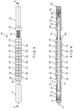
- Figure 1 is a cross-sectional view of an embodiment of the source wire assembly 10 of the present disclosure.
- Source wire assembly 10 is substantially rotationally symmetric about longitudinal axis 11 and is intended for radiographic uses such as, but not limited to, a radiographic projector which includes a curved or serpentine path.
- the curved or serpentine path of the radiographic projector is typically bounded by heavy radiological shielding.
- the curved or serpentine path in combination with the heavy radiological shielding, provides for substantially reduced radiation emitted through the path to the exterior, particularly if there is no line of sight from the exterior of the radiological projector to the radiological source of the source wire assembly 10.
- the total shielding is further increased, and the emitted radiation to the exterior of the radiographic projector is decreased, by the various metallic or otherwise shielding elements comprising the source wire assembly 10.
- Source wire assembly 10 includes an interior cylindrical core 12 of flexible metal cable.
- An exemplary, but non-limiting, embodiment of the flexible metal cable is shown in Figure 2 , wherein aircraft-type cable is presented with seven strands 13, each of the strands including seven metallic wires, resulting in what is commonly known as 7 x 7 aircraft cable.
- the wires are twisted, helix wound, woven, or braided together within each strand and the strands are likewise twisted, helix wound, woven or braided together to form the resulting cable.
- other configurations of aircraft cable or flexible metallic cable may be substituted for 7 x 7 aircraft cable.
- the various components of the source wire assembly 10 are mounted, directly or indirectly, on the cylindrical core 12. This allows the source wire assembly 10 to operate with freedom of movement in multiple planes and degrees of motion.
- Radioactive source capsule assembly 14 includes a radioactive gamma ray source 16 encased within a housing 18.
- the housing 18 includes a blind aperture 20 for receiving, surrounding and securing the distal end 22 of the cylindrical core 12. It is intended that a wide range of prior art or standard radioactive source capsule assemblies 14 may be adaptable to this embodiment.
- the source capsule assembly 14 is permanently attached to the cylindrical core 12. The source capsule assembly 14 being attached at the end of cylindrical core 12 allows for axial radiographic applications of the radiographic projector (not shown).
- the shield beads 26 are metallic toroidal rings with a central passageway through which the cylindrical core 12 passes.
- the shield beads 26 provide radiological shielding from the source capsule assembly 14.
- the cylindrical spacer sleeve 24 further assures that all gaps are filled between the shield beads 26, thereby eliminating or reducing any catch points.
- the cylindrical spacer sleeve 24 further aids in the permanent attachment process by preventing shield beads 26 from falling into the swaging assembly and further allows the active source capsule assembly 14 to be cut off when the assembly is returned for disposal.
- Shield beads 26 which are made from a gamma shielding material, such as, but not limited to, tungsten, are illustrated in Figure 1 as a series of ten individual toroidal rings abutting each other, with a hollow passageway through which cylindrical core 12 passes. Those skilled in the art, after review of the present disclosure, will recognize that a range of equivalent shielding materials may be used, depending upon the application. Shield beads 26 radiologically shield the proximal end of the source wire assembly 10, as well as any attached equipment such as the rear port of a radiographic projector (not shown), from the radioactive source 16. Shield beads 26 may further include beveled outer circular edges to aid in the flexure of the source wire assembly 10.
- a gamma shielding material such as, but not limited to, tungsten
- the leftmost or most distal shield bead 26 is of a reduced diameter and has a more pronounced chamfered face.
- the purpose of this profile is to gradually transfer from the larger diameter of the shield beads 26 to the smaller diameter of the sleeve 24. This helps to prevent or minimize "hang-up" incidents or accidents from occurring.
- the remaining shield beads 26 have a diameter for a tight tolerance within the passageway of the radiographic projector in order to provide sufficient radiological shielding.
- Spacer beads 28 and coil spring 30 sequentially engage the interior cylindrical core 12.
- the spacer beads 28 are typically made from a metal, such as, but not limited to, stainless steel. Those skilled in the art, after review of the present disclosure, will recognize that a range of equivalent materials may be used, depending upon the application.
- a first end of coil spring 30 may be engaged within undercut cylindrical slot 29 of rightmost spacer bead 28, radially outwardly adjacent from cylindrical core 12, in order to prevent coil spring 30 from riding over the chamfered surface of the rightmost spacer bead 28 and likewise eliminates or reduces any snagging of the first end of coil spring 30 during operation of the source wire assembly 10 (commonly known as a "hang-up incident" or "hang-up accident").
- Coil spring 30 further engages against connector housing 32 whereby a second end of coil spring 30 enters a cylindrical slot 33 formed by an indented relationship between sleeve 35 (swaged onto cylindrical core 12) and connector housing 32.
- This configuration is intended to eliminate or reduce any snagging of the second end of coil spring 30 during operation of the source wire assembly 10 (commonly known as a "hang-up incident” or "hang-up accident”).
- Connector housing 32 includes an enlarged distal lip 34 to further provide a diameter similar to or greater than that of shield beads 26 and spacer beads 28. This ensures that the source assembly adequately activates the source locking mechanism inside the radiographic projector (not shown) during operation.
- Cylindrical core 12 is engaged within the hollow interior 36 of connector housing 32 so that the proximal end of the cable 12 is surrounded by the enlarged distal lip 34 and sleeve 35.
- Hollow interior 36 further houses cylindrical connector shield 38, which may be made from tungsten, which provides further shielding to any attached equipment such as the rear port of a radiographic projector (not shown), from the radioactive source 16.
- Connector shield 38 may be biased in position by internal coil spring 40.
- Connector housing 32 further provides a standard connection device 42 for attachment to driving equipment, such as, but not limited to, a push-pull operation associated with a radiographic projector, which may include source wire locking and safety mechanisms.
- the two spacer beads 28 after the rightmost spacer bead 28 have been replaced by four additional shield beads 26 (with a single spacer bead 28 remaining in the rightmost position).
- This alternative embodiment of the source wire assembly 10 is expected to provide for increased shielding efficiency in the associated radiography projector (not shown) by reducing the radioactive dose emanating from the rear port of the projector (not shown) when the source wire assembly 10 is in the locked secure position. This results in increased safety to the operator or handler of the device and further provides a safety factor to avoid potential non-conforming shield efficiency profiles when the projector and the source wire assembly 10 enter the production stage of manufacture.
Landscapes
- Engineering & Computer Science (AREA)
- Health & Medical Sciences (AREA)
- Life Sciences & Earth Sciences (AREA)
- General Engineering & Computer Science (AREA)
- High Energy & Nuclear Physics (AREA)
- Physics & Mathematics (AREA)
- Medical Informatics (AREA)
- Animal Behavior & Ethology (AREA)
- Molecular Biology (AREA)
- Veterinary Medicine (AREA)
- Nuclear Medicine, Radiotherapy & Molecular Imaging (AREA)
- Optics & Photonics (AREA)
- Pathology (AREA)
- Radiology & Medical Imaging (AREA)
- Biomedical Technology (AREA)
- Heart & Thoracic Surgery (AREA)
- Biophysics (AREA)
- Surgery (AREA)
- Public Health (AREA)
- General Health & Medical Sciences (AREA)
- Oral & Maxillofacial Surgery (AREA)
- Mechanical Engineering (AREA)
- Ceramic Engineering (AREA)
- Metallurgy (AREA)
- Apparatus For Radiation Diagnosis (AREA)
- Projection Apparatus (AREA)
Description
- The present disclosure relates to a source wire assembly for radiographic applications, particularly for guiding a gamma ray source through a tubular path, such as with a radiographic projector. The source wire assembly includes a core of flexible metal cable, such as, but not limited to, aircraft cable, which may include wires and/or strands which are woven, helix wound, twisted or braided.
- An assembly as defined in the preamble of claim 1 is known from
US 6 166 388 A . - In the prior art, it is known to drive a gamma or other radiographic source though a tubular path in order to produce radiographic scans with respect to the integrity of a structure, such as a pipe or similar construction. This may be done in connection with a radiographic projector or similar device. Representative prior art includes
U.S. Published Patent Application 2011/0309272 entitled "Radiographic Projector", published on December 22, 2011 on behalf of Cole;U.S. Patent No. 6,627,908 entitled "Radiation Source Assembly and Connector Press Used in Producing Such Assemblies", issued on September 30, 2003 to Han et al.;U.S. Patent No. 6,481,914 entitled "Radiographic Source Connector with Improved Coupling Mechanism", issued on November 19, 2002 to Grenier et al.; andU.S. Patent No. 4,827,493 entitled "Radiographic Source", issued on May 2, 1989 to Parsons et al. - Typically, it is desired that a source wire assembly be somewhat stiff or rigid, but with flexibility to accommodate curvature within the tube path and elasticity so that the source wire assembly is not permanently deformed by the curvature within the path.
- It is therefore an object of the present disclosure to provide a source wire assembly which is stiff or rigid, but having sufficient flexibility to accommodate curvature within the tube path of a radiological projector (or similar equipment) and with sufficient elasticity to avoid permanent deformation within the curved path.
- This and other objects are attained by the present disclosure of a source wire assembly as defined in claim 1. The source wire assembly includes a core of flexible metal cable, such as, but not limited to, aircraft cable, which may include strands which are woven, helix wound, twisted, braided, or otherwise intertwined, the strands further including a plurality of metallic wires which may be woven, helix wound, twisted, braided or otherwise intertwined.
- This flexibility of the core provides the desired elasticity and eliminates or reduces any permanent deformation of the source wire assembly when driven through curved paths.
- Further objects and advantages of the disclosure will become apparent from the following description and from the accompanying drawings, wherein:
-
Figure 1 is a cross-sectional view an embodiment of the source wire assembly of the present disclosure. -
Figure 2 is a cross-sectional view of a non-exclusive example of flexible cable which may be used for the core of the source wire assembly ofFigure 1 . -
Figure 3 is a side plan view of an alternative embodiment of the source wire assembly of the present disclosure. -
Figure 4 is a cross-sectional view along plane 4-4 ofFigure 3 , illustrating an alternative embodiment of the source wire assembly of the present disclosure. - Referring now to the figures in detail, wherein like numerals indicate like elements throughout the several views, one sees that
Figure 1 is a cross-sectional view of an embodiment of thesource wire assembly 10 of the present disclosure. -
Source wire assembly 10 is substantially rotationally symmetric aboutlongitudinal axis 11 and is intended for radiographic uses such as, but not limited to, a radiographic projector which includes a curved or serpentine path. The curved or serpentine path of the radiographic projector is typically bounded by heavy radiological shielding. The curved or serpentine path, in combination with the heavy radiological shielding, provides for substantially reduced radiation emitted through the path to the exterior, particularly if there is no line of sight from the exterior of the radiological projector to the radiological source of thesource wire assembly 10. The total shielding is further increased, and the emitted radiation to the exterior of the radiographic projector is decreased, by the various metallic or otherwise shielding elements comprising thesource wire assembly 10. -
Source wire assembly 10 includes an interiorcylindrical core 12 of flexible metal cable. An exemplary, but non-limiting, embodiment of the flexible metal cable is shown inFigure 2 , wherein aircraft-type cable is presented with sevenstrands 13, each of the strands including seven metallic wires, resulting in what is commonly known as 7 x 7 aircraft cable. The wires are twisted, helix wound, woven, or braided together within each strand and the strands are likewise twisted, helix wound, woven or braided together to form the resulting cable. However, as will be appreciated by those skilled in the art after review of this disclosure, other configurations of aircraft cable or flexible metallic cable may be substituted for 7 x 7 aircraft cable. The various components of thesource wire assembly 10 are mounted, directly or indirectly, on thecylindrical core 12. This allows thesource wire assembly 10 to operate with freedom of movement in multiple planes and degrees of motion. - Radioactive
source capsule assembly 14 includes a radioactivegamma ray source 16 encased within ahousing 18. Thehousing 18 includes ablind aperture 20 for receiving, surrounding and securing thedistal end 22 of thecylindrical core 12. It is intended that a wide range of prior art or standard radioactivesource capsule assemblies 14 may be adaptable to this embodiment. Typically, thesource capsule assembly 14 is permanently attached to thecylindrical core 12. Thesource capsule assembly 14 being attached at the end ofcylindrical core 12 allows for axial radiographic applications of the radiographic projector (not shown). - A
cylindrical spacer sleeve 24, typically metallic, coaxially surrounds a portion of the cylindrical core and is used to space theradioactive source assembly 14 from theshield beads 26 and maintain the proper axial alignment of the various components. Theshield beads 26 are metallic toroidal rings with a central passageway through which thecylindrical core 12 passes. Theshield beads 26 provide radiological shielding from thesource capsule assembly 14. Thecylindrical spacer sleeve 24 further assures that all gaps are filled between theshield beads 26, thereby eliminating or reducing any catch points. The cylindrical spacer sleeve 24 further aids in the permanent attachment process by preventingshield beads 26 from falling into the swaging assembly and further allows the activesource capsule assembly 14 to be cut off when the assembly is returned for disposal. -
Shield beads 26, which are made from a gamma shielding material, such as, but not limited to, tungsten, are illustrated inFigure 1 as a series of ten individual toroidal rings abutting each other, with a hollow passageway through whichcylindrical core 12 passes. Those skilled in the art, after review of the present disclosure, will recognize that a range of equivalent shielding materials may be used, depending upon the application.Shield beads 26 radiologically shield the proximal end of thesource wire assembly 10, as well as any attached equipment such as the rear port of a radiographic projector (not shown), from theradioactive source 16.Shield beads 26 may further include beveled outer circular edges to aid in the flexure of thesource wire assembly 10. The leftmost or mostdistal shield bead 26 is of a reduced diameter and has a more pronounced chamfered face. The purpose of this profile is to gradually transfer from the larger diameter of theshield beads 26 to the smaller diameter of thesleeve 24. This helps to prevent or minimize "hang-up" incidents or accidents from occurring. However, theremaining shield beads 26 have a diameter for a tight tolerance within the passageway of the radiographic projector in order to provide sufficient radiological shielding. - Spacer beads 28 and
coil spring 30 sequentially engage the interiorcylindrical core 12. Thespacer beads 28 are typically made from a metal, such as, but not limited to, stainless steel. Those skilled in the art, after review of the present disclosure, will recognize that a range of equivalent materials may be used, depending upon the application. A first end ofcoil spring 30 may be engaged within undercutcylindrical slot 29 ofrightmost spacer bead 28, radially outwardly adjacent fromcylindrical core 12, in order to preventcoil spring 30 from riding over the chamfered surface of therightmost spacer bead 28 and likewise eliminates or reduces any snagging of the first end ofcoil spring 30 during operation of the source wire assembly 10 (commonly known as a "hang-up incident" or "hang-up accident"). The capturing of the interiorcylindrical core 12 of flexible metal cable bycylindrical spacer sleeve 24,coil spring 30 andbeads shield beads 26 andspacer beads 28 allow for minimal bend radii of the overallsource wire assembly 10. -
Coil spring 30 further engages againstconnector housing 32 whereby a second end ofcoil spring 30 enters a cylindrical slot 33 formed by an indented relationship between sleeve 35 (swaged onto cylindrical core 12) andconnector housing 32. This configuration is intended to eliminate or reduce any snagging of the second end ofcoil spring 30 during operation of the source wire assembly 10 (commonly known as a "hang-up incident" or "hang-up accident").Connector housing 32 includes an enlargeddistal lip 34 to further provide a diameter similar to or greater than that ofshield beads 26 andspacer beads 28. This ensures that the source assembly adequately activates the source locking mechanism inside the radiographic projector (not shown) during operation.Cylindrical core 12 is engaged within thehollow interior 36 of connector housing 32 so that the proximal end of thecable 12 is surrounded by the enlargeddistal lip 34 andsleeve 35.Hollow interior 36 further housescylindrical connector shield 38, which may be made from tungsten, which provides further shielding to any attached equipment such as the rear port of a radiographic projector (not shown), from theradioactive source 16.Connector shield 38 may be biased in position byinternal coil spring 40.Connector housing 32 further provides astandard connection device 42 for attachment to driving equipment, such as, but not limited to, a push-pull operation associated with a radiographic projector, which may include source wire locking and safety mechanisms. - In the alternative embodiment of the
source wire assembly 10 ofFigures 3 and 4 , the twospacer beads 28 after therightmost spacer bead 28 have been replaced by four additional shield beads 26 (with a single spacer bead 28 remaining in the rightmost position). This alternative embodiment of thesource wire assembly 10 is expected to provide for increased shielding efficiency in the associated radiography projector (not shown) by reducing the radioactive dose emanating from the rear port of the projector (not shown) when thesource wire assembly 10 is in the locked secure position. This results in increased safety to the operator or handler of the device and further provides a safety factor to avoid potential non-conforming shield efficiency profiles when the projector and thesource wire assembly 10 enter the production stage of manufacture. - Thus the several aforementioned objects and advantages are most effectively attained. Although preferred embodiments of the invention have been disclosed and described in detail herein, it should be understood that this invention is in no sense limited thereby.
Claims (14)
- A source wire assembly (10) for radiographic applications, including traversing a curved path of a radiographic projector, including:- an axial core (12) comprising a cable, the axial core (12) including a distal end (22) and a proximal end;- the distal end (22) including a device for holding a radiographic source (16) and the proximal end including a device for connecting to a drive apparatus; and- a plurality of toroidal rings mounted on the cable,wherein a first portion of the toroidal rings are metallic shielding beads (26),
characterized in that
the cable of the axial core (12) includes a plurality of strands (13), and that a second portion of the toroidal rings is at least one metallic spacer bead (28) positioned to a proximal side of the metallic shielding beads (26),
wherein the at least one metallic spacer bead (28) is comprised of stainless steel, and
wherein the plurality of strands (13) are comprised of metal. - The source wire assembly (10) of Claim 1,
wherein the plurality of strands (13) are intertwined with each other in a configuration chosen from the group consisting of twisted, helix wound, woven and braided. - The source wire assembly (10) of Claim 2,
wherein each of the strands (13) include a plurality of metal wires. - The source wire assembly (10) of Claim 3,
wherein the plurality of metal wires within each strand (13) are intertwined with each other in a configuration chosen from the group consisting of twisted, helix wound, woven and braided. - The source wire assembly (10) of one of the preceding Claims,
wherein the metallic shielding beads (26) are comprised of tungsten. - The source wire assembly (10) of one of the preceding Claims, further including a coil spring (30) wrapped around the core (12) and engaging, on a first end, a metallic spacer bead (28) and, on a second end, a housing (32) of the device for connecting to a drive apparatus.
- The source wire assembly (10) of Claim 8,
wherein the housing (32) further includes an enlarged lip (34) with a diameter equal to or greater than that of the plurality of toroidal rings. - The source wire assembly (10) of Claim 6 or 7,
wherein the metallic spacer bead (28) engaged by the first end of the coil spring (30) includes an undercut cylindrical slot (29) radially outward from the core (12) for receiving the first end of the coil spring (30). - The source wire assembly (10) of Claim 8,
wherein the second end of the spring (30) urges against the enlarged lip (34) of the housing (32). - The source wire assembly (10) of Claim 9,
wherein the enlarged lip (34) of the housing (32) surrounds a proximal end of the cable. - The source wire assembly (10) of one of the preceding Claims,
wherein the device for holding a radiological source (16) includes a blind aperture (20) for engaging and securing a distal end (22) of the cable. - The source wire assembly (10) of one of the preceding Claims,
further including a spacer sleeve (24) coaxially surrounding a portion of the cable, the spacer sleeve (24) including a first end and a second end, the first end of the spacer sleeve (24) abutting the device for holding a radiographic source (16) and the second end of the spacer sleeve (24) abutting a most distal metallic shielding bead . - The wire source assembly of one of the preceding Claims,
wherein the most distal metallic shielding bead (26) has a lesser diameter than a diameter of other shielding beads (26). - The source wire assembly (10) of one of the preceding Claims,
wherein the device for holding a radiological source (16) further includes a capsule assembly (14) for encasing a radiological source (16).
Priority Applications (1)
| Application Number | Priority Date | Filing Date | Title |
|---|---|---|---|
| PL16798016T PL3329495T3 (en) | 2015-07-28 | 2016-05-11 | Source wire assembly for radiographic applications |
Applications Claiming Priority (3)
| Application Number | Priority Date | Filing Date | Title |
|---|---|---|---|
| US201562197873P | 2015-07-28 | 2015-07-28 | |
| US201562268720P | 2015-12-17 | 2015-12-17 | |
| PCT/US2016/031736 WO2017019148A1 (en) | 2015-07-28 | 2016-05-11 | Source wire assembly for radiographic applications |
Publications (2)
| Publication Number | Publication Date |
|---|---|
| EP3329495A1 EP3329495A1 (en) | 2018-06-06 |
| EP3329495B1 true EP3329495B1 (en) | 2019-11-20 |
Family
ID=57346041
Family Applications (1)
| Application Number | Title | Priority Date | Filing Date |
|---|---|---|---|
| EP16798016.8A Active EP3329495B1 (en) | 2015-07-28 | 2016-05-11 | Source wire assembly for radiographic applications |
Country Status (6)
| Country | Link |
|---|---|
| US (1) | US10403410B2 (en) |
| EP (1) | EP3329495B1 (en) |
| KR (1) | KR102512189B1 (en) |
| CN (1) | CN108028084B (en) |
| PL (1) | PL3329495T3 (en) |
| WO (1) | WO2017019148A1 (en) |
Families Citing this family (1)
| Publication number | Priority date | Publication date | Assignee | Title |
|---|---|---|---|---|
| US20260018311A1 (en) * | 2024-05-23 | 2026-01-15 | Qsa Global Inc. | Radiography sources and radiation exposure devices having keyed locking devices |
Family Cites Families (13)
| Publication number | Priority date | Publication date | Assignee | Title |
|---|---|---|---|---|
| GB2061080B (en) | 1979-10-06 | 1984-08-30 | Pantatron Systems Ltd | Shielding container |
| US4827493A (en) | 1987-10-05 | 1989-05-02 | Amersham Corporation | Radiographic source |
| CN2149007Y (en) * | 1993-01-16 | 1993-12-08 | 中国原子能科学研究院 | Improved annular neutron source |
| US5460592A (en) * | 1994-01-24 | 1995-10-24 | Amersham Holdings, Inc. | Apparatus and method for making carrier assembly for radioactive seed carrier |
| GB9601502D0 (en) | 1996-01-25 | 1996-03-27 | Weir Donald | Source guide tube for radiography source projector system, system containing tube and flexible radiation attenuating sleeve for a tube |
| US6159165A (en) * | 1997-12-05 | 2000-12-12 | Micrus Corporation | Three dimensional spherical micro-coils manufactured from radiopaque nickel-titanium microstrand |
| AU745288B2 (en) * | 1998-02-12 | 2002-03-21 | Robert Robertson | Encapsulated low-energy brachytherapy sources |
| US6481914B1 (en) | 1999-04-08 | 2002-11-19 | Aea Technology Qsa Inc. | Radiographic source connector with improved coupling mechanism |
| MXPA02000375A (en) * | 1999-07-14 | 2002-07-30 | Novoste Corp | Radioactive source train. |
| US6627908B1 (en) | 1999-08-17 | 2003-09-30 | Korea Atomic Energy Research Institute | Radiation source assembly and connector press used in producing such assemblies |
| US6773390B2 (en) * | 2002-03-20 | 2004-08-10 | Cordis Corporation | Radioactive source ribbon assembly |
| US7199375B2 (en) * | 2004-10-12 | 2007-04-03 | Bard Brachytherapy, Inc. | Radiation shielding container that encloses a vial of one or more radioactive seeds |
| GB0902353D0 (en) | 2009-02-13 | 2009-04-01 | Gilligan Engineering Services | Radiographic projector |
-
2016
- 2016-05-11 PL PL16798016T patent/PL3329495T3/en unknown
- 2016-05-11 CN CN201680042672.6A patent/CN108028084B/en active Active
- 2016-05-11 WO PCT/US2016/031736 patent/WO2017019148A1/en not_active Ceased
- 2016-05-11 EP EP16798016.8A patent/EP3329495B1/en active Active
- 2016-05-11 KR KR1020187001581A patent/KR102512189B1/en active Active
- 2016-05-11 US US15/742,978 patent/US10403410B2/en active Active
Non-Patent Citations (1)
| Title |
|---|
| None * |
Also Published As
| Publication number | Publication date |
|---|---|
| EP3329495A1 (en) | 2018-06-06 |
| US20180226164A1 (en) | 2018-08-09 |
| CN108028084B (en) | 2021-06-18 |
| US10403410B2 (en) | 2019-09-03 |
| KR20180033175A (en) | 2018-04-02 |
| CN108028084A (en) | 2018-05-11 |
| WO2017019148A1 (en) | 2017-02-02 |
| PL3329495T3 (en) | 2020-06-01 |
| KR102512189B1 (en) | 2023-03-20 |
Similar Documents
| Publication | Publication Date | Title |
|---|---|---|
| DE10023392A1 (en) | Curved section for insertion section of endoscope; has connection rings containing rotatable guide elements with guide holes for curve control wire and stop devices to secure them in connection rings | |
| EP3586344B1 (en) | Irradiation targets for the production of radioisotopes and related method of manufacturing | |
| US20090264883A1 (en) | Radiolucent orthopedic fixation plate | |
| US10403410B2 (en) | Source wire assembly for radiographic applications | |
| EP3712312B1 (en) | Net, tether accommodating device, and method for producing net | |
| KR20180019507A (en) | Temperature measurement unit with tubular spring | |
| WO2015136064A1 (en) | Endoscope having a distal electrical feed-through and method for assembling an endoscope | |
| EP3361109B1 (en) | Control cable | |
| WO2007054769A3 (en) | Method and apparatus for radiation imaging | |
| JP7134861B2 (en) | Optical fiber cable and method for manufacturing optical fiber cable | |
| CA3039810A1 (en) | Delivering radiation | |
| EP2984672B1 (en) | Arrangement for a quick electron beam x-ray computer tomography | |
| EP3518012B1 (en) | Optical fiber unit and optical fiber cable | |
| CA2243672C (en) | Source guide tube for radiography source projector system, system containing tube and flexible radiation attenuating sleeve for a tube | |
| CN102592928A (en) | X-ray tube with secondary discharge attenuation | |
| US20220132646A1 (en) | Methods and apparatus for control of radiographic source exposure | |
| GB2061080A (en) | Shielding container | |
| EP4030087B1 (en) | Hose device and method for producing a hose device | |
| CN213140999U (en) | Cable winding device | |
| CN119828302B (en) | A radiation-resistant tubular material shielding structure | |
| CN218899834U (en) | Medical stent system | |
| SU468565A1 (en) | Magazine of nuclear reactor | |
| CN210073385U (en) | High-strength shielded cable | |
| EP3199090A1 (en) | Endoscope flexible tube | |
| DE102007059047A1 (en) | Geiger-Muller counter for use as measuring device for measuring radioactivity in electrical system, has anode and cathode that are electrically connected with evaluation unit, where cathode and anode are bendably designed |
Legal Events
| Date | Code | Title | Description |
|---|---|---|---|
| STAA | Information on the status of an ep patent application or granted ep patent |
Free format text: STATUS: UNKNOWN |
|
| STAA | Information on the status of an ep patent application or granted ep patent |
Free format text: STATUS: THE INTERNATIONAL PUBLICATION HAS BEEN MADE |
|
| PUAI | Public reference made under article 153(3) epc to a published international application that has entered the european phase |
Free format text: ORIGINAL CODE: 0009012 |
|
| STAA | Information on the status of an ep patent application or granted ep patent |
Free format text: STATUS: REQUEST FOR EXAMINATION WAS MADE |
|
| 17P | Request for examination filed |
Effective date: 20180103 |
|
| AK | Designated contracting states |
Kind code of ref document: A1 Designated state(s): AL AT BE BG CH CY CZ DE DK EE ES FI FR GB GR HR HU IE IS IT LI LT LU LV MC MK MT NL NO PL PT RO RS SE SI SK SM TR |
|
| AX | Request for extension of the european patent |
Extension state: BA ME |
|
| DAV | Request for validation of the european patent (deleted) | ||
| DAX | Request for extension of the european patent (deleted) | ||
| STAA | Information on the status of an ep patent application or granted ep patent |
Free format text: STATUS: EXAMINATION IS IN PROGRESS |
|
| 17Q | First examination report despatched |
Effective date: 20181203 |
|
| GRAP | Despatch of communication of intention to grant a patent |
Free format text: ORIGINAL CODE: EPIDOSNIGR1 |
|
| STAA | Information on the status of an ep patent application or granted ep patent |
Free format text: STATUS: GRANT OF PATENT IS INTENDED |
|
| INTG | Intention to grant announced |
Effective date: 20190613 |
|
| GRAS | Grant fee paid |
Free format text: ORIGINAL CODE: EPIDOSNIGR3 |
|
| GRAA | (expected) grant |
Free format text: ORIGINAL CODE: 0009210 |
|
| STAA | Information on the status of an ep patent application or granted ep patent |
Free format text: STATUS: THE PATENT HAS BEEN GRANTED |
|
| AK | Designated contracting states |
Kind code of ref document: B1 Designated state(s): AL AT BE BG CH CY CZ DE DK EE ES FI FR GB GR HR HU IE IS IT LI LT LU LV MC MK MT NL NO PL PT RO RS SE SI SK SM TR |
|
| REG | Reference to a national code |
Ref country code: GB Ref legal event code: FG4D |
|
| REG | Reference to a national code |
Ref country code: CH Ref legal event code: EP |
|
| REG | Reference to a national code |
Ref country code: DE Ref legal event code: R096 Ref document number: 602016024792 Country of ref document: DE |
|
| REG | Reference to a national code |
Ref country code: IE Ref legal event code: FG4D |
|
| REG | Reference to a national code |
Ref country code: AT Ref legal event code: REF Ref document number: 1205114 Country of ref document: AT Kind code of ref document: T Effective date: 20191215 |
|
| REG | Reference to a national code |
Ref country code: NL Ref legal event code: MP Effective date: 20191120 |
|
| REG | Reference to a national code |
Ref country code: LT Ref legal event code: MG4D |
|
| PG25 | Lapsed in a contracting state [announced via postgrant information from national office to epo] |
Ref country code: BG Free format text: LAPSE BECAUSE OF FAILURE TO SUBMIT A TRANSLATION OF THE DESCRIPTION OR TO PAY THE FEE WITHIN THE PRESCRIBED TIME-LIMIT Effective date: 20200220 Ref country code: NO Free format text: LAPSE BECAUSE OF FAILURE TO SUBMIT A TRANSLATION OF THE DESCRIPTION OR TO PAY THE FEE WITHIN THE PRESCRIBED TIME-LIMIT Effective date: 20200220 Ref country code: FI Free format text: LAPSE BECAUSE OF FAILURE TO SUBMIT A TRANSLATION OF THE DESCRIPTION OR TO PAY THE FEE WITHIN THE PRESCRIBED TIME-LIMIT Effective date: 20191120 Ref country code: GR Free format text: LAPSE BECAUSE OF FAILURE TO SUBMIT A TRANSLATION OF THE DESCRIPTION OR TO PAY THE FEE WITHIN THE PRESCRIBED TIME-LIMIT Effective date: 20200221 Ref country code: SE Free format text: LAPSE BECAUSE OF FAILURE TO SUBMIT A TRANSLATION OF THE DESCRIPTION OR TO PAY THE FEE WITHIN THE PRESCRIBED TIME-LIMIT Effective date: 20191120 Ref country code: LV Free format text: LAPSE BECAUSE OF FAILURE TO SUBMIT A TRANSLATION OF THE DESCRIPTION OR TO PAY THE FEE WITHIN THE PRESCRIBED TIME-LIMIT Effective date: 20191120 Ref country code: LT Free format text: LAPSE BECAUSE OF FAILURE TO SUBMIT A TRANSLATION OF THE DESCRIPTION OR TO PAY THE FEE WITHIN THE PRESCRIBED TIME-LIMIT Effective date: 20191120 Ref country code: NL Free format text: LAPSE BECAUSE OF FAILURE TO SUBMIT A TRANSLATION OF THE DESCRIPTION OR TO PAY THE FEE WITHIN THE PRESCRIBED TIME-LIMIT Effective date: 20191120 |
|
| PG25 | Lapsed in a contracting state [announced via postgrant information from national office to epo] |
Ref country code: IS Free format text: LAPSE BECAUSE OF FAILURE TO SUBMIT A TRANSLATION OF THE DESCRIPTION OR TO PAY THE FEE WITHIN THE PRESCRIBED TIME-LIMIT Effective date: 20200320 Ref country code: HR Free format text: LAPSE BECAUSE OF FAILURE TO SUBMIT A TRANSLATION OF THE DESCRIPTION OR TO PAY THE FEE WITHIN THE PRESCRIBED TIME-LIMIT Effective date: 20191120 Ref country code: RS Free format text: LAPSE BECAUSE OF FAILURE TO SUBMIT A TRANSLATION OF THE DESCRIPTION OR TO PAY THE FEE WITHIN THE PRESCRIBED TIME-LIMIT Effective date: 20191120 |
|
| PG25 | Lapsed in a contracting state [announced via postgrant information from national office to epo] |
Ref country code: AL Free format text: LAPSE BECAUSE OF FAILURE TO SUBMIT A TRANSLATION OF THE DESCRIPTION OR TO PAY THE FEE WITHIN THE PRESCRIBED TIME-LIMIT Effective date: 20191120 |
|
| PG25 | Lapsed in a contracting state [announced via postgrant information from national office to epo] |
Ref country code: ES Free format text: LAPSE BECAUSE OF FAILURE TO SUBMIT A TRANSLATION OF THE DESCRIPTION OR TO PAY THE FEE WITHIN THE PRESCRIBED TIME-LIMIT Effective date: 20191120 Ref country code: DK Free format text: LAPSE BECAUSE OF FAILURE TO SUBMIT A TRANSLATION OF THE DESCRIPTION OR TO PAY THE FEE WITHIN THE PRESCRIBED TIME-LIMIT Effective date: 20191120 Ref country code: EE Free format text: LAPSE BECAUSE OF FAILURE TO SUBMIT A TRANSLATION OF THE DESCRIPTION OR TO PAY THE FEE WITHIN THE PRESCRIBED TIME-LIMIT Effective date: 20191120 Ref country code: RO Free format text: LAPSE BECAUSE OF FAILURE TO SUBMIT A TRANSLATION OF THE DESCRIPTION OR TO PAY THE FEE WITHIN THE PRESCRIBED TIME-LIMIT Effective date: 20191120 Ref country code: PT Free format text: LAPSE BECAUSE OF FAILURE TO SUBMIT A TRANSLATION OF THE DESCRIPTION OR TO PAY THE FEE WITHIN THE PRESCRIBED TIME-LIMIT Effective date: 20200412 |
|
| REG | Reference to a national code |
Ref country code: AT Ref legal event code: MK05 Ref document number: 1205114 Country of ref document: AT Kind code of ref document: T Effective date: 20191120 |
|
| REG | Reference to a national code |
Ref country code: DE Ref legal event code: R097 Ref document number: 602016024792 Country of ref document: DE |
|
| PG25 | Lapsed in a contracting state [announced via postgrant information from national office to epo] |
Ref country code: SM Free format text: LAPSE BECAUSE OF FAILURE TO SUBMIT A TRANSLATION OF THE DESCRIPTION OR TO PAY THE FEE WITHIN THE PRESCRIBED TIME-LIMIT Effective date: 20191120 Ref country code: SK Free format text: LAPSE BECAUSE OF FAILURE TO SUBMIT A TRANSLATION OF THE DESCRIPTION OR TO PAY THE FEE WITHIN THE PRESCRIBED TIME-LIMIT Effective date: 20191120 |
|
| PLBE | No opposition filed within time limit |
Free format text: ORIGINAL CODE: 0009261 |
|
| STAA | Information on the status of an ep patent application or granted ep patent |
Free format text: STATUS: NO OPPOSITION FILED WITHIN TIME LIMIT |
|
| 26N | No opposition filed |
Effective date: 20200821 |
|
| PG25 | Lapsed in a contracting state [announced via postgrant information from national office to epo] |
Ref country code: AT Free format text: LAPSE BECAUSE OF FAILURE TO SUBMIT A TRANSLATION OF THE DESCRIPTION OR TO PAY THE FEE WITHIN THE PRESCRIBED TIME-LIMIT Effective date: 20191120 Ref country code: SI Free format text: LAPSE BECAUSE OF FAILURE TO SUBMIT A TRANSLATION OF THE DESCRIPTION OR TO PAY THE FEE WITHIN THE PRESCRIBED TIME-LIMIT Effective date: 20191120 |
|
| PG25 | Lapsed in a contracting state [announced via postgrant information from national office to epo] |
Ref country code: LI Free format text: LAPSE BECAUSE OF NON-PAYMENT OF DUE FEES Effective date: 20200531 Ref country code: MC Free format text: LAPSE BECAUSE OF FAILURE TO SUBMIT A TRANSLATION OF THE DESCRIPTION OR TO PAY THE FEE WITHIN THE PRESCRIBED TIME-LIMIT Effective date: 20191120 Ref country code: CH Free format text: LAPSE BECAUSE OF NON-PAYMENT OF DUE FEES Effective date: 20200531 Ref country code: IT Free format text: LAPSE BECAUSE OF FAILURE TO SUBMIT A TRANSLATION OF THE DESCRIPTION OR TO PAY THE FEE WITHIN THE PRESCRIBED TIME-LIMIT Effective date: 20191120 |
|
| PG25 | Lapsed in a contracting state [announced via postgrant information from national office to epo] |
Ref country code: LU Free format text: LAPSE BECAUSE OF NON-PAYMENT OF DUE FEES Effective date: 20200511 |
|
| PG25 | Lapsed in a contracting state [announced via postgrant information from national office to epo] |
Ref country code: FR Free format text: LAPSE BECAUSE OF NON-PAYMENT OF DUE FEES Effective date: 20200531 Ref country code: IE Free format text: LAPSE BECAUSE OF NON-PAYMENT OF DUE FEES Effective date: 20200511 |
|
| PG25 | Lapsed in a contracting state [announced via postgrant information from national office to epo] |
Ref country code: TR Free format text: LAPSE BECAUSE OF FAILURE TO SUBMIT A TRANSLATION OF THE DESCRIPTION OR TO PAY THE FEE WITHIN THE PRESCRIBED TIME-LIMIT Effective date: 20191120 Ref country code: MT Free format text: LAPSE BECAUSE OF FAILURE TO SUBMIT A TRANSLATION OF THE DESCRIPTION OR TO PAY THE FEE WITHIN THE PRESCRIBED TIME-LIMIT Effective date: 20191120 Ref country code: CY Free format text: LAPSE BECAUSE OF FAILURE TO SUBMIT A TRANSLATION OF THE DESCRIPTION OR TO PAY THE FEE WITHIN THE PRESCRIBED TIME-LIMIT Effective date: 20191120 |
|
| PG25 | Lapsed in a contracting state [announced via postgrant information from national office to epo] |
Ref country code: MK Free format text: LAPSE BECAUSE OF FAILURE TO SUBMIT A TRANSLATION OF THE DESCRIPTION OR TO PAY THE FEE WITHIN THE PRESCRIBED TIME-LIMIT Effective date: 20191120 |
|
| P01 | Opt-out of the competence of the unified patent court (upc) registered |
Effective date: 20230606 |
|
| PGFP | Annual fee paid to national office [announced via postgrant information from national office to epo] |
Ref country code: PL Payment date: 20250422 Year of fee payment: 10 Ref country code: DE Payment date: 20250529 Year of fee payment: 10 |
|
| PGFP | Annual fee paid to national office [announced via postgrant information from national office to epo] |
Ref country code: GB Payment date: 20250527 Year of fee payment: 10 |
|
| PGFP | Annual fee paid to national office [announced via postgrant information from national office to epo] |
Ref country code: BE Payment date: 20250527 Year of fee payment: 10 |
|
| PGFP | Annual fee paid to national office [announced via postgrant information from national office to epo] |
Ref country code: CZ Payment date: 20250425 Year of fee payment: 10 |