EP3329478B1 - Wireless emergency alert notifications - Google Patents
Wireless emergency alert notifications Download PDFInfo
- Publication number
- EP3329478B1 EP3329478B1 EP16744999.0A EP16744999A EP3329478B1 EP 3329478 B1 EP3329478 B1 EP 3329478B1 EP 16744999 A EP16744999 A EP 16744999A EP 3329478 B1 EP3329478 B1 EP 3329478B1
- Authority
- EP
- European Patent Office
- Prior art keywords
- message
- alert message
- audio
- language
- notification server
- Prior art date
- Legal status (The legal status is an assumption and is not a legal conclusion. Google has not performed a legal analysis and makes no representation as to the accuracy of the status listed.)
- Active
Links
Images




Classifications
-
- H—ELECTRICITY
- H04—ELECTRIC COMMUNICATION TECHNIQUE
- H04L—TRANSMISSION OF DIGITAL INFORMATION, e.g. TELEGRAPHIC COMMUNICATION
- H04L41/00—Arrangements for maintenance, administration or management of data switching networks, e.g. of packet switching networks
- H04L41/06—Management of faults, events, alarms or notifications
- H04L41/0631—Management of faults, events, alarms or notifications using root cause analysis; using analysis of correlation between notifications, alarms or events based on decision criteria, e.g. hierarchy, tree or time analysis
-
- G—PHYSICS
- G08—SIGNALLING
- G08B—SIGNALLING SYSTEMS, e.g. PERSONAL CALLING SYSTEMS; ORDER TELEGRAPHS; ALARM SYSTEMS
- G08B25/00—Alarm systems in which the location of the alarm condition is signalled to a central station, e.g. fire or police telegraphic systems
- G08B25/01—Alarm systems in which the location of the alarm condition is signalled to a central station, e.g. fire or police telegraphic systems characterised by the transmission medium
- G08B25/10—Alarm systems in which the location of the alarm condition is signalled to a central station, e.g. fire or police telegraphic systems characterised by the transmission medium using wireless transmission systems
-
- G—PHYSICS
- G06—COMPUTING OR CALCULATING; COUNTING
- G06F—ELECTRIC DIGITAL DATA PROCESSING
- G06F40/00—Handling natural language data
- G06F40/40—Processing or translation of natural language
-
- G—PHYSICS
- G08—SIGNALLING
- G08B—SIGNALLING SYSTEMS, e.g. PERSONAL CALLING SYSTEMS; ORDER TELEGRAPHS; ALARM SYSTEMS
- G08B17/00—Fire alarms; Alarms responsive to explosion
-
- G—PHYSICS
- G08—SIGNALLING
- G08B—SIGNALLING SYSTEMS, e.g. PERSONAL CALLING SYSTEMS; ORDER TELEGRAPHS; ALARM SYSTEMS
- G08B17/00—Fire alarms; Alarms responsive to explosion
- G08B17/06—Electric actuation of the alarm, e.g. using a thermally-operated switch
-
- G—PHYSICS
- G08—SIGNALLING
- G08B—SIGNALLING SYSTEMS, e.g. PERSONAL CALLING SYSTEMS; ORDER TELEGRAPHS; ALARM SYSTEMS
- G08B21/00—Alarms responsive to a single specified undesired or abnormal condition and not otherwise provided for
- G08B21/18—Status alarms
- G08B21/24—Reminder alarms, e.g. anti-loss alarms
-
- G—PHYSICS
- G08—SIGNALLING
- G08B—SIGNALLING SYSTEMS, e.g. PERSONAL CALLING SYSTEMS; ORDER TELEGRAPHS; ALARM SYSTEMS
- G08B25/00—Alarm systems in which the location of the alarm condition is signalled to a central station, e.g. fire or police telegraphic systems
- G08B25/009—Signalling of the alarm condition to a substation whose identity is signalled to a central station, e.g. relaying alarm signals in order to extend communication range
-
- G—PHYSICS
- G08—SIGNALLING
- G08B—SIGNALLING SYSTEMS, e.g. PERSONAL CALLING SYSTEMS; ORDER TELEGRAPHS; ALARM SYSTEMS
- G08B25/00—Alarm systems in which the location of the alarm condition is signalled to a central station, e.g. fire or police telegraphic systems
- G08B25/14—Central alarm receiver or annunciator arrangements
-
- G—PHYSICS
- G08—SIGNALLING
- G08B—SIGNALLING SYSTEMS, e.g. PERSONAL CALLING SYSTEMS; ORDER TELEGRAPHS; ALARM SYSTEMS
- G08B3/00—Audible signalling systems, e.g. audible personal calling systems
- G08B3/10—Audible signalling systems, e.g. audible personal calling systems using electric transmission; using electromagnetic transmission
-
- G—PHYSICS
- G10—MUSICAL INSTRUMENTS; ACOUSTICS
- G10L—SPEECH ANALYSIS TECHNIQUES OR SPEECH SYNTHESIS; SPEECH RECOGNITION; SPEECH OR VOICE PROCESSING TECHNIQUES; SPEECH OR AUDIO CODING OR DECODING
- G10L13/00—Speech synthesis; Text to speech systems
-
- G—PHYSICS
- G08—SIGNALLING
- G08B—SIGNALLING SYSTEMS, e.g. PERSONAL CALLING SYSTEMS; ORDER TELEGRAPHS; ALARM SYSTEMS
- G08B1/00—Systems for signalling characterised solely by the form of transmission of the signal
- G08B1/08—Systems for signalling characterised solely by the form of transmission of the signal using electric transmission ; transformation of alarm signals to electrical signals from a different medium, e.g. transmission of an electric alarm signal upon detection of an audible alarm signal
Definitions
- This application relates to a safety alarm system that signals an emergency condition.
- Audio capabilities enable emergency communication to be passed between fire control panels and/or audio panels in an alarm system.
- audio capabilities have been integrated with building fire alarm systems such as mass notification systems, the need has emerged for alerts to be tailored or directed to individuals.
- individuals with unique requirements may be present in a building or on a campus.
- Such individuals may have a disability or problems understanding the language or words in a typical alert message that is broadcast in a building via fire control panels and/or audio panels.
- US 2013/154822 A1 discloses a method for alarm event notification from a server system in relation to a premises such as a home or building.
- the server system acts as a centralized monitoring and notification security system for monitoring of the premises and receiving an alarm event from an on-premises monitoring system.
- the method includes: receiving in a server system an alarm event in relation to the premises, determining a presence status of a client application, generating a message in relation to the alarm event, and sending the message to the client application having the presence status of being present.
- the message may be generated to include message content
- US 2003/067386 A1 discloses methods and an apparatus for detecting the occurrence of an event and notifying a user of the event as well as the nature of the event.
- Verification of the crash event may be performed at the server in a variety of ways, including the simultaneous receipt of crash event notifications from multiple co-located devices. What is needed in the art is an approach for generating and sending directed messages to individuals that may be tailored to the individual's needs or limitations. which varies in dependence of capabilities of the client application having the presence status of being present.
- US 2003/067386 A1 discloses methods and an apparatus for detecting the occurrence of an event and notifying a user of the event as well as the nature of the event. The user can be in practically any local or remote location relative to the location of the event. The user can establish criteria in accordance with which an alerting message is routed to any of various destinations which can be various types of communication devices monitored by the user.
- a safety alarm system is damaged during an emergency and is unable to send audio messages via the buildings fire panels and speakers.
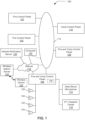
- the building fire and audio alarm system may have numerous fire control panels, such as fire control panels 102 and 104, fire and voice control panels 106 and 108, and voice control panels 110. In other implementations there may be more or fewer devices in the building fire and audio alarm system. In yet other implementations, additional panels such as security panels or HVAC control panels may be present.
- the panels 102-110 may be networked together by a data network 112.
- the data network may have a physical layer of wire, radio waves, fiber optic cables, coaxial cable, or a combination of any of the above. Over the physical layer, additional protocol layers may be implemented to carry data, such as a TCP/IP network (commonly called the internet).
- the data network 112 may be configured as a local area network (LAN) that connects the panels and building automation systems.
- LAN local area network
- the fire and voice control panel such as fire and voice control panel 106, may have associated desk mounted microphones 114 and/or connection to an emergency center, such as a 911 dispatch center 116. Additionally, the fire and voice control panel 106 may have audio outputs for connection to speakers, such as speaker 128-134 and/or amplifiers (not shown). In other implementations, the desk microphone 114 may be an internal microphone or other audio input device.
- the fire control panel 106 may also be coupled via the internet 118 to a notification server, such as internet notification server 126 and a wireless station server 120 that enable communication with wired or wireless communication devices.
- the internet notification server 126 may resides in the cloud (distributed network) coupled to the internet 118 or be located locally.
- An example of a wireless station server 120 is a server that resides in a cellular communication network and is able to communicate with wireless devices (for example wireless device 122) such as tables, smartphones, or similar devices. Communication may also be achieved over wired network with wired devices such as computer 124.
- Computer 124 is shown as connected to the internet 118, but in other implementations it may be coupled indirectly to the internet via other networks (see dotted lines in FIG. 1 ). Examples of messaging (wired or wireless) may include instant messaging text messaging, electronic mail (email), and/or smart devices notification message (text or digitized messaging such as digitized audio).
- FIG. 2 a block diagram 200 of the fire and voice control panel 106 is depicted in accordance with an example implementation of the invention.
- the desk mounted microphone 114 may be connected to a microphone module 202 that supports one or more audio inputs 203 (two in the current example).
- the microphone module 202 is in signal communication with an input analog audio handling module 204.
- the input analog audio handling module 204 may provide separate channels to an ADC DAC codec 206 that is able to handle two audio channel inputs.
- the ADC DAC codec 206 may have a 48 kHz sampling rate with at least a 16 bit resolution.
- the analog to digital converter (ADC) and digital to analog converter (DAC) in the ADC DAC codec 206 may be implemented as slave devices.
- the analog channels may then be routed to the output analog audio handling module 208 for transmission on one of the analog outputs 210.
- One or more amplifiers and/or speakers may be in signal communication with the digital audio router 212, such as amplifiers 228-234 via I2S buses 236 and 238 (two I2S buses are used in the current example).
- I2S buses 236 and 238 each have a respective L and R channels, i.e. 240, 242 and 244, 246.
- the output of each of the amplifiers 228-238 may be connected to speakers 118-124 of FIG. 1 respectively.
- a supervisory module 236 may monitor the operation of the fire and voice control panel 106.
- a block diagram 300 of the fire and voice control panel 106 in communication with wireless device 122 and computer 124 of FIG. 1 is depicted in accordance with an example implementation of the invention.
- the fire and voice control panel 106 pushes a text based message to a cloud gateway 314 that is able to send the message 302 to internet notification server 126 in the form of an email, SMS, instant message, tweet, text, or similar text message and/or to wireless station server 120.
- the message 302 is converted in the cloud gateway 314 from a text message into a first audio alert message 310 (another message) having a first language (i.e. English) via the text-to-speech translation module 304 in the internet notification server 126.
- the text-to-speech translation may occur in the wireless station server 120.
- the message 302 may also be converted into a second audio alert message 312 having a second language (i.e. German) by the multilingual speech translation module 306 in the internet notification server 126.
- the multilingual speech translations may occur in the wireless station server 120.
- the multilingual speech translation module 306 may convert the first audio alert message from the text-to-speech translation module 304 into the second audio alert message 312 having the second language.
- a database 308 may be associated with the wireless station server 120 that identifies the devices (such as wireless device 102, 122, and/or 124) to receive one of the audio alert messages 310 or 312. Part of that database may also identify the language of the alert message. For example, a German user's wireless communication device would be identifiable in database 308 and the wireless station server would only send the second audio alert message that has been translated into German to that wireless communication device.
- the wireless station server 120 also may provide supervision between the fire and voice control panel 106 and the wireless station server 120.
- the supervision may be a periodic supervision message that is sent at predetermined times, such as every hour.
- the periodic supervision message when received at the wireless station server 120, may result in a wireless supervision message being sent to a cellular modem 136 located or associated with the fire and voice control panel 106.
- sending a supervision message from the fire and voice control panel 106, internet 118, wireless station server 120, resulting in a wireless supervision message being sent to the cellular modem 136 verifies the communication path is operational.
- supervision may be accomplished between the computer 124, wireless device 122, and other fire control panels (such as 102) by periodically sending at predetermined times, supervision messages to those devices.
- a device receiving the supervision message responds with a supervision acknowledgement message.
- An application may be running on the computer 124, wireless device 122, and other fire control panels, that monitor the communication link for supervision messages. When the application receives the supervision message, a supervision acknowledgement message is generated and sent back to the fire and voice control panel 106 via network 112, internet 118, and/or cellular modem 136.
- the fire and voice control panel 106 may track which communication devices respond to supervision messages and generate alerts or logs of identifying what communication devices have and/or have not responded to the supervision messages.
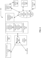
- FIG. 4 a block diagram 400 of the fire and voice control panel 106 sending a first audio alert message 310 via an emergency notification module 402 to wireless device 122 is depicted in accordance with an example implementation of the invention.
- An audio or text message may be send to the cloud (internet notification server 126) and then onto the wireless station server 120 from the fire and voice control panel 106.
- the internet notification server 126 may then translate the message if needed using modules 304 and/or 306. It is noted that the internet notification server 126 and cloud gateway 314 are implemented as a single device or co-located device.
- the resulting audio alert message 310 or 312 may then be sent to wireless device 122 by wireless emergency alert (WEA).
- WEA wireless emergency alert
- the WEA may be a vibration and/or unique audio sound.
- WEA enables government officials to target emergency alerts to specific geographic areas (e.g. lower Manhattan) through cell towers. The cell towers broadcast the emergency alerts for reception by WEA-enabled mobile devices.
- WEA complements the existing Emergency Alert System (EAS) which is implemented by the FCC and FEMA at the federal level through broadcasters and other media service providers.
- EAS Emergency Alert System
- WEA and the EAS are part of FEMA's Integrated Public Alert and Warning System (IPAWS).
- Wireless companies volunteer to participate in WEA, which is the result of a unique public/private partnership between the FCC, FEMA and the wireless industry to enhance public safety. Participating wireless carriers were required to deploy WEA by April 7, 2012.
- a block diagram 500 of the fire and voice control panel 106 of FIG. 1 sending a message 302 as a text message 508 via the wireless station server 120 is depicted in accordance with an example implementation of the invention.
- the fire and voice control panel 106 may send a message 302 (audio message) to be played at voice and fire panels located in the building or campus.
- the message may also be sent via the internet or other network (i.e. phone, wireless, Packet) to a wireless station server 120.
- the internet notification server 126 has a speech-to-text translation module 504 that translates the audio message into a text message 508.
- the text message 508 may also be translated into different language (either predefined or identified from database 308) via the multilingual translation module 506.
- the text messages 508 may then be sent from the internet notification server 126 to wireless device 122, fire control panel 102 (if fire control panels are configured to receive text messages), computer 124, and notification devices 510.
- the selection of the text message (i.e. which language) may be based upon information contained in the database 308.
- the information in the database 308 contains an identifier for a device (such as wireless device 122) and a language identifier.
- Notification devices include LED scroll messaging boards, ticker displays on monitors, and similar text displaying devices.
- the text message 508 may be broadcast via a cellular wireless network that is in communication with the wireless station server 120.
- the fire control panel may have the capability to send and receive text messages. This may be accomplished by incorporating a cellular modem 136 in the fire control panels, such as fire control panel 102, fire and voice control panel 108, and voice control panel
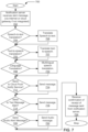
- a flow diagram 700 of an approach for notification of devices i.e. 122, 102, 124, and 510) from fire and voice control panel 106 is depicted in accordance with and example implementation of the invention.
- the notification server such as internet notification server 126, receives a message (i.e. alert message) in step 702.
- the message may originate from a fire and voice control panel 106 or the internet.
- a cloud gateway 314 may also assist in the transmission of the message from fire and voice control panel 106 and/or internet. In other implementations, other types of panels may generate the message.
- the audio message in step 704 may be converted to a text based message by the text-to-speech translation module 304 in step 706. If the message received at the internet notification server is a text based message, then the text message in step 705 may be converted to an audio (i.e. speech) message in step 707. If the message needs to be converted into a different language in step 708, then the message may be translated into another language by the multilingual speech translation in step 710.
- the message may be sent from the internet notification server 126 to the cloud push notify server 604 in step 714.
- the message may be sent via the internet or other network connections. If the text based message need to be sent as a text alert message 508 in step 714, then may be sent to a wireless station server 120 or directly to other networked devices (i.e. 102, 124, and 510) in step 718. If an audio message 310 and/or 312 needs to be sent in step 720, then the audio message may be sent by the internet notification server 126 to wireless station server 120, fire control panel 102, and/or computer 124 in step 722.
- the notification server in step 724 may receive confirmation that the sent message in step 714, 718, and/or 722 was received.
- FIG. 8 a flow diagram 800 of an approach for alert messages being passed between fire panels, such as panels 102 and 106 in accordance with an example implementation of the invention is depicted.
- An alert message may be received at fire and voice control panel 106 in step 802 via a wireless modem 136.
- the message may then be formatted for transmission to other fire control panels in step 804.
- the formatting may include security being added to the message for verification at the receiving panel.
- the formatted alert message may then be sent as text or encoded digitized audio to other control panels in step 806.
- a confirmation may be received at the sending fire control panel, such as fire and voice control panel 106, from the fire control panel that received the alert message in step 808.
- a confirmation of receipt message may be generated and sent by the fire and voice control panel 106 to the originator of the initial alert message in step 810.
- one or more processes, sub-processes, or process steps described in connection with Figs. 7-8 may be performed by hardware and/or software (machine readable instructions). If the approach is performed by software, the software may reside in software memory (not shown) in a suitable electronic processing component or system such as one or more of the functional components or modules schematically depicted in the figures.
Landscapes
- Physics & Mathematics (AREA)
- Engineering & Computer Science (AREA)
- General Physics & Mathematics (AREA)
- Emergency Management (AREA)
- Business, Economics & Management (AREA)
- Computational Linguistics (AREA)
- Health & Medical Sciences (AREA)
- Audiology, Speech & Language Pathology (AREA)
- Theoretical Computer Science (AREA)
- Computer Networks & Wireless Communication (AREA)
- Human Computer Interaction (AREA)
- Multimedia (AREA)
- Acoustics & Sound (AREA)
- Artificial Intelligence (AREA)
- General Health & Medical Sciences (AREA)
- General Engineering & Computer Science (AREA)
- Signal Processing (AREA)
- Electromagnetism (AREA)
- Alarm Systems (AREA)
Description
- This application relates to a safety alarm system that signals an emergency condition.
- In alarm systems, such as building fire alarm systems, it is desirable to have alert capabilities such as audio and visual alert capabilities. Audio capabilities enable emergency communication to be passed between fire control panels and/or audio panels in an alarm system. As audio capabilities have been integrated with building fire alarm systems such as mass notification systems, the need has emerged for alerts to be tailored or directed to individuals. At times, individuals with unique requirements may be present in a building or on a campus. Such individuals may have a disability or problems understanding the language or words in a typical alert message that is broadcast in a building via fire control panels and/or audio panels.
-
US 2013/154822 A1 discloses a method for alarm event notification from a server system in relation to a premises such as a home or building. The server system acts as a centralized monitoring and notification security system for monitoring of the premises and receiving an alarm event from an on-premises monitoring system. The method includes: receiving in a server system an alarm event in relation to the premises, determining a presence status of a client application, generating a message in relation to the alarm event, and sending the message to the client application having the presence status of being present. The message may be generated to include message contentUS 2003/067386 A1 discloses methods and an apparatus for detecting the occurrence of an event and notifying a user of the event as well as the nature of the event. The user can be in practically any local or remote location relative to the location of the event. The user can establish criteria in accordance with which an alerting message is routed to any of various destinations which can be various types of communication devices monitored by the user. The user can also establish criteria in accordance with which the mode of the alerting message is presented to the user.
US 2014/070939 A1 discloses an interactive wireless life safety communications system. A central coordination server is linked to a first network, over which there is a connection to at least one resident life safety device at a specific location or for specific resident. An alarm signal is generated by the resident life safety device upon detection of an alarm condition and transmitted to the central coordination server. A caregiver communications device is connected to the central coordination server over a second network, and is receptive to an alarm notification that is generated by the central coordination server in response to the alarm signal. The caregiver communications device is also receptive to a caregiver user input, from which an action status response is generated for transmission to the central coordination server.
US 2011/279263 A1 discloses a location aware mobile device including an accelerometer or similar motion sensing component that can measure changes in speed or direction. An application executing in the mobile device can determine whether particular motion changes are indicative of the mobile device being involved in a crash event. If the motion parameters indicate that a crash event has occurred, the mobile device can communicate a crash event notification to a server, which can alert an emergency response unit about the crash, including the crash location, without the need for human intervention. Verification of the crash event may be performed at the server in a variety of ways, including the simultaneous receipt of crash event notifications from multiple co-located devices.
What is needed in the art is an approach for generating and sending directed messages to individuals that may be tailored to the individual's needs or limitations.
which varies in dependence of capabilities of the client application having the presence status of being present.
US 2003/067386 A1 discloses methods and an apparatus for detecting the occurrence of an event and notifying a user of the event as well as the nature of the event. The user can be in practically any local or remote location relative to the location of the event. The user can establish criteria in accordance with which an alerting message is routed to any of various destinations which can be various types of communication devices monitored by the user. The user can also establish criteria in accordance with which the mode of the alerting message is presented to the user.
US 2014/070939 A1 discloses an interactive wireless life safety communications system. A central coordination server is linked to a first network, over which there is a connection to at least one resident life safety device at a specific location or for specific resident. An alarm signal is generated by the resident life safety device upon detection of an alarm condition and transmitted to the central coordination server. A caregiver communications device is connected to the central coordination server over a second network, and is receptive to an alarm notification that is generated by the central coordination server in response to the alarm signal. The caregiver communications device is also receptive to a caregiver user input, from which an action status response is generated for transmission to the central coordination server.
US 2011/279263 A1 discloses a location aware mobile device including an accelerometer or similar motion sensing component that can measure changes in speed or direction. An application executing in the mobile device can determine whether particular motion changes are indicative of the mobile device being involved in a crash event. If the motion parameters indicate that a crash event has occurred, the mobile device can communicate a crash event notification to a server, which can alert an emergency response unit about the crash, including the crash location, without the need for human intervention. Verification of the crash event may be performed at the server in a variety of ways, including the simultaneous receipt of crash event notifications from multiple co-located devices.
What is needed in the art is an approach for generating and sending directed messages to individuals that may be tailored to the individual's needs or limitations. - In accordance with one embodiment of the disclosure, a safety alarm system having the features of claim 1 is described.
- It is also possible that a safety alarm system is damaged during an emergency and is unable to send audio messages via the buildings fire panels and speakers. In such instances, it is advantageous to have a second communication approach or path to send alert messages to building or campus occupants.
- The above described features and advantages, as well as others, will become more readily apparent to those of ordinary skill in the art by reference to the following detailed description and accompanying drawings. While it is desirable to provide notification (sometime referred to as alerts) to user communication devices, the teachings disclosed herein also extend to those embodiments which fall within the scope of the appended claims, regardless of whether they accomplish one or more of the above-mentioned advantages.
-
-
FIG. 1 is an exemplary topology diagram for a building fire alarm system; -
FIG. 2 is a block diagram of the fire and voice control panel ofFIG. 1 is depicted in accordance with an example implementation of the invention; -
FIG. 3 is a block diagram 300 of the fire and voice control panel in communication with wireless device and computer ofFIG. 1 in accordance with an example implementation of the invention; -
FIG. 4 is a block diagram of the fire and voice control panel ofFIG.1 sending a first audio alert message via an emergency notification module to wireless device in accordance with an example implementation of the invention. -
FIG. 5 is a block diagram of the fire and voice control panel sending a first audio alert message as text via the wireless station server ofFIG. 1 in accordance with an example implementation of the invention; -
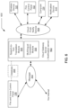
FIG. 6 is a block diagram of the fire and voice control panel ofFIG. 1 sending a message to a cloud gateway server to format the message to be pushed to user communication device in accordance with an example implementation of the invention; -
Fig. 7 is a flow diagram of an approach for notification of devices from fire and voice control panel is depicted in accordance with and example implementation of the invention; and -
Fig. 8 is a flow diagram of an approach for alert messages being passed between fire panels is depicted in accordance with an example implementation of the invention. - An example emergency alert notification approach for handling fire alarm and notification events is presented.
- With reference to
Fig. 1 , an exemplary topology diagram 100 for a building fire and audio alarm system (safety alarm system) approach is shown. The building fire and audio alarm system may have numerous fire control panels, such asfire control panels voice control panels voice control panels 110. In other implementations there may be more or fewer devices in the building fire and audio alarm system. In yet other implementations, additional panels such as security panels or HVAC control panels may be present. The panels 102-110 may be networked together by adata network 112. The data network may have a physical layer of wire, radio waves, fiber optic cables, coaxial cable, or a combination of any of the above. Over the physical layer, additional protocol layers may be implemented to carry data, such as a TCP/IP network (commonly called the internet). Thedata network 112 may be configured as a local area network (LAN) that connects the panels and building automation systems. - The fire and voice control panel, such as fire and
voice control panel 106, may have associated desk mountedmicrophones 114 and/or connection to an emergency center, such as a 911 dispatch center 116. Additionally, the fire andvoice control panel 106 may have audio outputs for connection to speakers, such as speaker 128-134 and/or amplifiers (not shown). In other implementations, thedesk microphone 114 may be an internal microphone or other audio input device. - The
fire control panel 106 may also be coupled via theinternet 118 to a notification server, such asinternet notification server 126 and awireless station server 120 that enable communication with wired or wireless communication devices. Theinternet notification server 126 may resides in the cloud (distributed network) coupled to theinternet 118 or be located locally. An example of awireless station server 120 is a server that resides in a cellular communication network and is able to communicate with wireless devices (for example wireless device 122) such as tables, smartphones, or similar devices. Communication may also be achieved over wired network with wired devices such ascomputer 124.Computer 124 is shown as connected to theinternet 118, but in other implementations it may be coupled indirectly to the internet via other networks (see dotted lines inFIG. 1 ). Examples of messaging (wired or wireless) may include instant messaging text messaging, electronic mail (email), and/or smart devices notification message (text or digitized messaging such as digitized audio). - Turning to
Fig. 2 , a block diagram 200 of the fire andvoice control panel 106 is depicted in accordance with an example implementation of the invention. The desk mountedmicrophone 114 may be connected to amicrophone module 202 that supports one or more audio inputs 203 (two in the current example). Themicrophone module 202 is in signal communication with an input analogaudio handling module 204. The input analogaudio handling module 204 may provide separate channels to anADC DAC codec 206 that is able to handle two audio channel inputs. TheADC DAC codec 206 may have a 48 kHz sampling rate with at least a 16 bit resolution. The analog to digital converter (ADC) and digital to analog converter (DAC) in theADC DAC codec 206 may be implemented as slave devices. The analog channels may then be routed to the output analogaudio handling module 208 for transmission on one of the analog outputs 210. - The
ADC DAC codec 206 also communicates withDigital Audio Router 212 that may be implemented with a field-programmable gate array (FPGA) via a two-wayI2S audio bus 214. An I2S audio bus (also called I2S, Inter-IC Sound, Integrated Interchip Sound, or IIS) is an electrical serial bus interface that consists of three lines, 1) bit clock line, 2) word clock line, and 3) at least one multiplexed data line. It may also include a master clock and a multiplexed data line for upload. Typically the I2S bus carries PCM digital audio data or signals. The I2S allows two channels to be sent on the same data line. The two channels are commonly called right (R) channel and left (L) channel. The word clock is typically a 50% duty-cycle signal that has the same frequency as the sample frequency. The I2S audio bus is defined by the Philips Semiconductor I2S bus specification (February 1986, revised June 5, 1996). - The
Digital audio router 212 enables digitized audio, such as digitized analog audio frommicrophone 114 may be provided to anIP audio module 216. TheIP audio module 216 converts the digitized audio into voice over IP (VOIP) encoded data. An example of theIP audio module 216 isIP Audio Module 102 produced by BARIX. The output of theIP audio module 216 is VOIP encoded data. The VOIP encoded data is made available to aswitch 218 that enables the VOIP encoded data to be transported by an IP network (Ethernet 220) bynetwork interface 222.Network interface 222 may also be coupled to theinternet 118. - The
digital audio router 212 may also be connected tomemory 224 via adata bus 226, where pre-recorded digitized audio messages may be stored inmemory 224. The memory may also store metrics and operational data for the Fire and Voice Control Panel's operation. Thememory 224 may be implemented as electronic nonvolatile computer storage device that can be electrically erased and reprogrammed, i.e. flash memory. In other implementations, other types of memory such as RAM, DRAM, SDRAM, EEPROM may be employed. - One or more amplifiers and/or speakers may be in signal communication with the
digital audio router 212, such as amplifiers 228-234 viaI2S buses 236 and 238 (two I2S buses are used in the current example). Each of thebuses FIG. 1 respectively. Asupervisory module 236 may monitor the operation of the fire andvoice control panel 106. - In
Fig. 3 , a block diagram 300 of the fire andvoice control panel 106 in communication withwireless device 122 andcomputer 124 ofFIG. 1 is depicted in accordance with an example implementation of the invention. The fire andvoice control panel 106 pushes a text based message to acloud gateway 314 that is able to send themessage 302 tointernet notification server 126 in the form of an email, SMS, instant message, tweet, text, or similar text message and/or towireless station server 120. Themessage 302 is converted in thecloud gateway 314 from a text message into a first audio alert message 310 (another message) having a first language (i.e. English) via the text-to-speech translation module 304 in theinternet notification server 126. In other implementations, the text-to-speech translation may occur in thewireless station server 120. Themessage 302 may also be converted into a second audioalert message 312 having a second language (i.e. German) by the multilingualspeech translation module 306 in theinternet notification server 126. In other implementations the multilingual speech translations may occur in thewireless station server 120. In yet other implementations, the multilingualspeech translation module 306 may convert the first audio alert message from the text-to-speech translation module 304 into the second audioalert message 312 having the second language. - Modules, such as multilingual
speech translation module 306 and text-to-speech translation module 304 may be implemented in software (plurality of machine readable instructions), hardware, or a combination of software and hardware. Examples of existing text-to-speech translation software include NATURALREADER, ULTRA HAL TTS READER, and READCLIP. Examples of existing speech-to-text software include NUANCE COMMUNICATIONS' DRAGON NATURALLY SPEAKING, SPEECHGEAR INTERACT, and BRAINA. - The first audio
alert message 310 and second audioalert message 312 may be sent towireless devices 122 via wireless networks and via the internet protocol to fire control panels (such as fire control panel 102) andcomputers 124. These devices then may play the first or second audio message on the device. In other implementations, the audio message may be streamed audio messages. In yet other implementations, the audio messages may trigger dedicated applications running on thewireless device 122,computer 124, and/orfire control panel 102 to play the alert audio messages. - A
database 308 may be associated with thewireless station server 120 that identifies the devices (such aswireless device alert messages database 308 and the wireless station server would only send the second audio alert message that has been translated into German to that wireless communication device. - The
wireless station server 120 also may provide supervision between the fire andvoice control panel 106 and thewireless station server 120. The supervision may be a periodic supervision message that is sent at predetermined times, such as every hour. The periodic supervision message, when received at thewireless station server 120, may result in a wireless supervision message being sent to acellular modem 136 located or associated with the fire andvoice control panel 106. Thus, sending a supervision message from the fire andvoice control panel 106,internet 118,wireless station server 120, resulting in a wireless supervision message being sent to thecellular modem 136 verifies the communication path is operational. - Similarly, supervision may be accomplished between the
computer 124,wireless device 122, and other fire control panels (such as 102) by periodically sending at predetermined times, supervision messages to those devices. A device receiving the supervision message responds with a supervision acknowledgement message. An application may be running on thecomputer 124,wireless device 122, and other fire control panels, that monitor the communication link for supervision messages. When the application receives the supervision message, a supervision acknowledgement message is generated and sent back to the fire andvoice control panel 106 vianetwork 112,internet 118, and/orcellular modem 136. The fire andvoice control panel 106 may track which communication devices respond to supervision messages and generate alerts or logs of identifying what communication devices have and/or have not responded to the supervision messages. - Turning to
Fig. 4 , a block diagram 400 of the fire andvoice control panel 106 sending a first audioalert message 310 via anemergency notification module 402 towireless device 122 is depicted in accordance with an example implementation of the invention. An audio or text message may be send to the cloud (internet notification server 126) and then onto thewireless station server 120 from the fire andvoice control panel 106. Theinternet notification server 126 may then translate the message if needed usingmodules 304 and/or 306. It is noted that theinternet notification server 126 andcloud gateway 314 are implemented as a single device or co-located device. The resulting audioalert message wireless device 122 by wireless emergency alert (WEA). The WEA may be a vibration and/or unique audio sound. An advantage to the WEA approach is everyone in an area covered by sectors of a cellular cell or micro cell across a campus will received notification. Multiple notifications such the first audioalert message 310 and second audioalert message 312 may be sent one after the other to everyone covered by the cellular or micro cell sites. - The WEA service (formerly known as the Commercial Mobile Alert System (CMAS) or Personal Localized Alerting Network (PLAN)) is a public safety system that allows customers who own certain wireless phone models and other enabled mobile devices to receive geographically-targeted, text-like messages alerting them of imminent threats to safety in their area. The technology ensures that emergency alerts will not get stuck in highly congested areas, which can happen with standard mobile voice and texting services. WEA was established pursuant to the Warning, Alert and Response Network (WARN) Act.
- WEA enables government officials to target emergency alerts to specific geographic areas (e.g. lower Manhattan) through cell towers. The cell towers broadcast the emergency alerts for reception by WEA-enabled mobile devices. WEA complements the existing Emergency Alert System (EAS) which is implemented by the FCC and FEMA at the federal level through broadcasters and other media service providers. WEA and the EAS are part of FEMA's Integrated Public Alert and Warning System (IPAWS). Wireless companies volunteer to participate in WEA, which is the result of a unique public/private partnership between the FCC, FEMA and the wireless industry to enhance public safety. Participating wireless carriers were required to deploy WEA by April 7, 2012.
- Pre-authorized national, state or local governments may send emergency alerts regarding public safety emergencies, such as evacuation orders or shelter in place orders due to severe weather, a terrorist threat or chemical spill, to WEA. Alerts from authenticated public safety officials are sent through FEMA's IPAWS to participating wireless carriers. Participating wireless carriers push the alerts from cell towers to mobile devices in the affected area. The alerts appear like text messages on mobile devices. Alerts are broadcast only from cell towers in the zone of an emergency. The alerts are geographically targeted to cell towers in the location of the emergency. Phones that are using the cell towers in the alert zone will receive the WEA. This means that if an alert is sent to an area in New York, all WEA-capable phones in the alert area can receive the WEA, even if they are phones that are roaming or visiting from another state. In other words, a customer visiting New York from Chicago would receive alerts in New York if they have a WEA-enabled mobile device and their phone is using a cell tower in the alert zone in New York.
- In
Fig. 5 , a block diagram 500 of the fire andvoice control panel 106 ofFIG. 1 sending amessage 302 as atext message 508 via thewireless station server 120 is depicted in accordance with an example implementation of the invention. The fire andvoice control panel 106 may send a message 302 (audio message) to be played at voice and fire panels located in the building or campus. The message may also be sent via the internet or other network (i.e. phone, wireless, Packet) to awireless station server 120. Theinternet notification server 126 has a speech-to-text translation module 504 that translates the audio message into atext message 508. The text message 508 (another message) may also be translated into different language (either predefined or identified from database 308) via themultilingual translation module 506. Thetext messages 508 may then be sent from theinternet notification server 126 towireless device 122, fire control panel 102 (if fire control panels are configured to receive text messages),computer 124, andnotification devices 510. The selection of the text message (i.e. which language) may be based upon information contained in thedatabase 308. The information in thedatabase 308 contains an identifier for a device (such as wireless device 122) and a language identifier. Notification devices include LED scroll messaging boards, ticker displays on monitors, and similar text displaying devices. Thetext message 508 may be broadcast via a cellular wireless network that is in communication with thewireless station server 120. In other implementations, the fire control panel may have the capability to send and receive text messages. This may be accomplished by incorporating acellular modem 136 in the fire control panels, such asfire control panel 102, fire andvoice control panel 108, andvoice control panel 110. - It is understood that the
modules emergency notification module 402 enables direct communication with wireless station servers and may be implemented as a cellular communication device. - Turning to
Fig. 6 , a block diagram 600 of the fire andvoice control panel 106 ofFIG. 1 sending amessage 302 to acloud gateway server 602 to format the message to be pushed to user communication device is depicted in accordance with an example implementation of the invention. The fire andvoice control panel 106 may send amessage 302 to acloud gateway 602. The message fire andvoice control panel 106 may be coupled to the cloud gateway via a network connection using a SSH tunnel with a socket connectivity to thecloud gateway server 602. Examples of a cloud gateway server include a server on Amazon's EC2, Google App Engine or Microsoft Azure. Thecloud gateway server 602 may convert the message into a format that can be "pushed" down to user communication devices. A cloud push notifyserver 604 may then push the message to devices such aswireless device 122,fire control panel 102,computer 124, andnotification device 510. The cloud gateway server may provide the functions of the internet notification server. In some implementations the cloud gateway server may be a sub-type ofinternet notification server 126. - The devices that receive the "pushed" message may receive the message at an application that is running as a back ground application. Upon receipt of the "pushed" message, the application may respond to the cloud gateway server when the message is accessed or read. The message may also consist of a URL of the audio message which may be automatically played on the wireless devices once received.
- In
Fig. 7 , a flow diagram 700 of an approach for notification of devices (i.e. 122, 102, 124, and 510) from fire andvoice control panel 106 is depicted in accordance with and example implementation of the invention. The notification server, such asinternet notification server 126, receives a message (i.e. alert message) instep 702. The message may originate from a fire andvoice control panel 106 or the internet. Acloud gateway 314 may also assist in the transmission of the message from fire andvoice control panel 106 and/or internet. In other implementations, other types of panels may generate the message. If the message received at the internet notification server is an audio based message, then the audio message instep 704 may be converted to a text based message by the text-to-speech translation module 304 instep 706. If the message received at the internet notification server is a text based message, then the text message instep 705 may be converted to an audio (i.e. speech) message instep 707. If the message needs to be converted into a different language instep 708, then the message may be translated into another language by the multilingual speech translation instep 710. - If the text alert message needs to be sent to a cloud push notify
server 604 instep 712, then the message may be sent from theinternet notification server 126 to the cloud push notifyserver 604 instep 714. The message may be sent via the internet or other network connections. If the text based message need to be sent as atext alert message 508 instep 714, then may be sent to awireless station server 120 or directly to other networked devices (i.e. 102, 124, and 510) instep 718. If anaudio message 310 and/or 312 needs to be sent instep 720, then the audio message may be sent by theinternet notification server 126 towireless station server 120,fire control panel 102, and/orcomputer 124 instep 722. The notification server instep 724 may receive confirmation that the sent message instep - Turning to
Fig. 8 , a flow diagram 800 of an approach for alert messages being passed between fire panels, such aspanels voice control panel 106 instep 802 via awireless modem 136. The message may then be formatted for transmission to other fire control panels instep 804. The formatting may include security being added to the message for verification at the receiving panel. The formatted alert message may then be sent as text or encoded digitized audio to other control panels instep 806. A confirmation may be received at the sending fire control panel, such as fire andvoice control panel 106, from the fire control panel that received the alert message instep 808. A confirmation of receipt message may be generated and sent by the fire andvoice control panel 106 to the originator of the initial alert message instep 810. - It will be understood, and is appreciated by persons skilled in the art, that one or more processes, sub-processes, or process steps described in connection with
Figs. 7-8 may be performed by hardware and/or software (machine readable instructions). If the approach is performed by software, the software may reside in software memory (not shown) in a suitable electronic processing component or system such as one or more of the functional components or modules schematically depicted in the figures. - The software in software memory may include an ordered listing of executable instructions for implementing logical functions (that is, "logic" that may be implemented either in digital form such as digital circuitry or source code or in analog form such as analog circuitry or an analog source such an analog electrical, sound or video signal), and may selectively be embodied in any computer-readable medium for use by or in connection with an instruction execution system, apparatus, or device, such as a computer-based system, processor-containing system, or other system that may selectively fetch the instructions from the instruction execution system, apparatus, or device and execute the instructions. In the context of this disclosure, a "computer-readable medium" is any tangible means that may contain or store the program for use by or in connection with the instruction execution system, apparatus, or device. The tangible computer readable medium may selectively be, for example, but is not limited to, an electronic, magnetic, optical, electromagnetic, infrared, or semiconductor system, apparatus or device. More specific examples, but nonetheless a non-exhaustive list, of tangible computer-readable media would include the following: a portable computer diskette (magnetic), a RAM (electronic), a read-only memory "ROM" (electronic), an erasable programmable read-only memory (EPROM or Flash memory) (electronic) and a portable compact disc read-only memory "CDROM" (optical). Note that the computer-readable medium may even be paper (punch cards or punch tape) or another suitable medium upon which the instructions may be electronically captured, then compiled, interpreted or otherwise processed in a suitable manner if necessary, and stored in a computer memory.
- The foregoing detailed description of one or more embodiments of the approach for handling fire alarm and notification events has been presented herein by way of example only and not limitation. It will be recognized that there are advantages to certain individual features and functions described herein that may be obtained without incorporating other features and functions described herein. Presently unforeseen or unanticipated alternatives, modifications, variations, or improvements therein may be subsequently made by those skilled in the art which are also intended to be encompassed by the appended claims.
Claims (15)
- A safety alarm system (100) that signals an emergency condition, comprising:a notification server (126) with a network interface;a wireless station server (120) configured to enable communication with communication devices (102, 122, 124);a database (308) associated with the wireless station server (120), wherein the database (308) contains identifiers for the communication devices (102, 122, 124) and a language identifier; anda control panel (106) configured to push a text-based alert message (302) to a cloud gateway (314) that is able to send the alert message (302) to the notification server (126),where the notification server (126) is arranged for receiving the alert message (302) at the network interface and for converting the alert message (302) into a first audio alert message (310) and a second audio alert message (312) being formatted for transmission to communication devices (102, 122, 124) and where the first audio alert message (310) and the second audio alert message (312) provide notice of the emergency condition,where the first audio alert message (310) having a first language is converted in a cloud gateway (314) from a text message via a text-to-speech translation module (304) in the notification server (126),where the second audio alert message (312) having a second language is converted by a multilingual speech translation module (306, 506) in the notification server (126),where the wireless station server (120) identifies the communication devices (102, 122, 124) to receive one of the first audio alert message (310) or the second audio alert message (312) based on the language of the alert message (302) identified by part of the database, andwherein the notification server (126) and the cloud gateway (314) are implemented as a single device or co-located device.
- A safety alarm system (100) of claim 1, where the notification server (126) is a cloud gateway sever (602) and the one of the first audio alert message (310) or the second audio alert message (312) is a pushed message sent for receipt by a cloud push notify service (604) to the communication devices (102, 122, 124), the pushed message is configured for consisting of a URL of an audio message which is configured for automatically playing on the communication devices (102, 122, 124) once received.
- The safety alarm system (100) of claim 1, where the notification server (126) is an internet notification server and the alert message (302) is received via internet.
- The safety alarm system of claim 1, where the alert message (302) is a text message and results in the first audio alert message (310) that is generated by the text-to-speech translation module (304), and where the second audio alert message (312) is in particular changed from the first language to the second language by the multilingual speech translation module (306, 506).
- The safety alarm system (100) of claim 1, where the alert message (302) is a text message having the first language and results in the second audio alert message (312) with a audio message having the second language.
- The safety alarm system (100) of claim 1, where the notification server (126) is an internet notification server where the first audio alert message (310) and the second audio alert message (312) are digital audio messages formatted for transmission by an emergency notification module (402) for receipt by the communication devices (102, 122, 124).
- The safety alarm system (100) of claim 1, where the alert message (302) is a digital audio message that results in a text message (508) by a speech-to-text translation module (504), and where the text message (508) is in particular translated from the first language to the second language by the multilingual translation module (306, 506).
- The safety alarm system (100) of claim 1 where the notification server (126) is a fire control panel (106) and the communication device is another fire control panel (102).
- A method for signal of an emergency condition in a safety alarm system (100), comprising:coupling a notification server (126) at a network interface with a network (118);pushing a text-based alert message (302) to a cloud gateway (314) that is able to send the alert message to the notification server (126);receiving (802) the alert message (302) at the network interface;converting the alert message (302) into a first audio alert message (310) and a second audio alert message (312) for transmission to the at least one communication device (102, 122, 124) in response to receipt of the alert message (302), where the first audio alert message (310) and the second audio alert message (312) provide notice of the emergency condition;identifying, in database (308) associated with a wireless station server (120), the communication devices (102, 122, 124) to receive one of the first audio alert message (310) or the second audio alert message (312), based on the language of the alert message (302) identified by part of the database, wherein the database (308) contains identifiers for the communication devices (102, 122, 124) and a language identifier, where the wireless station server (120) enables communication with the communication devices (102, 122, 124),where the first audio alert message (310) having a first language is converted via a text-to-speech translation module (304) in the notification server (126),where the second audio alert message (312) having a second language is converted by a multilingual speech translation module (306, 506) in the notification server (126), andwherein the notification server (126) and the cloud gateway (314) are implemented as a single device or co-located device.
- The method for signaling of an emergency condition in a safety alarm system (100) of claim 9, where the notification server (126) is a cloud gateway sever (602) and the one of the first audio alert message (310) or the second audio alert message (312) is a pushed message sent for receipt by a cloud push notify service (604) to the communication devices (102, 122, 124), and includes, automatically playing an audio message on the communication devices (102, 122, 124) once the pushed message consisting of a URL of the audio message is received.
- The method for signaling of an emergency condition in a safety alarm system (100) of claim 9 includes, receiving the alert message (302) via the internet (118) and where the notification server (126) is an internet notification server (126).
- The method for signaling of an emergency condition in a safety alarm system (100) of claim 9, where the first audio alert message (310) is generated with the text-to-speech translation module (304) in response to receipt of the alert message (302) where the alert message (302) is a text message, and where the second audio alert message (312) is in particular changed from a first language to a second language by the multilingual speech translation module (306, 506).
- The method for signaling of an emergency condition in a safety alarm system (100) of claim 9 where first audio alert message (310) and the second audio alert message (312) are digital audio messages for transmission by an emergency notification module (402) located at the notification server (126) for receipt by communication devices (102,122, 124), where the notification server (126) is an internet notification server.
- The method for signaling of an emergency condition in a safety alarm system (100) of claim 9, further comprising converting (706) the alert message (302) that is a digital audio message into a text message (508) with a speech-to-text translation module (504), and in particular translating (710) the text message (508) from the first language to the second language with the multilingual translation module (306, 506).
- The method for signaling of an emergency condition in a safety alarm system (100) of claim 9 includes, translating the alert message (302) that is a digital audio message in the first language into a text message (508) in the second language.
Applications Claiming Priority (2)
| Application Number | Priority Date | Filing Date | Title |
|---|---|---|---|
| US14/815,410 US10249174B2 (en) | 2015-07-31 | 2015-07-31 | Wireless emergency alert notifications |
| PCT/US2016/042018 WO2017023501A1 (en) | 2015-07-31 | 2016-07-13 | Wireless emergency alert notifications |
Publications (3)
| Publication Number | Publication Date |
|---|---|
| EP3329478A1 EP3329478A1 (en) | 2018-06-06 |
| EP3329478C0 EP3329478C0 (en) | 2025-04-09 |
| EP3329478B1 true EP3329478B1 (en) | 2025-04-09 |
Family
ID=56551582
Family Applications (1)
| Application Number | Title | Priority Date | Filing Date |
|---|---|---|---|
| EP16744999.0A Active EP3329478B1 (en) | 2015-07-31 | 2016-07-13 | Wireless emergency alert notifications |
Country Status (8)
| Country | Link |
|---|---|
| US (1) | US10249174B2 (en) |
| EP (1) | EP3329478B1 (en) |
| KR (1) | KR102063452B1 (en) |
| CN (2) | CN116527475A (en) |
| BR (1) | BR112018000189B1 (en) |
| CA (1) | CA2994108C (en) |
| MX (1) | MX391119B (en) |
| WO (1) | WO2017023501A1 (en) |
Families Citing this family (18)
| Publication number | Priority date | Publication date | Assignee | Title |
|---|---|---|---|---|
| US10129916B1 (en) | 2017-05-11 | 2018-11-13 | Honeywell International Inc. | System and method for controlling network parameters for a plurality of home security/home system control panels |
| US10176366B1 (en) * | 2017-11-01 | 2019-01-08 | Sorenson Ip Holdings Llc | Video relay service, communication system, and related methods for performing artificial intelligence sign language translation services in a video relay service environment |
| US20190197855A1 (en) * | 2017-12-22 | 2019-06-27 | Carrier Corporation | Emergency notification system and method |
| WO2019161230A1 (en) * | 2018-02-15 | 2019-08-22 | Federal Signal Corporation | Localized distribution of emergency mass notification alerts |
| WO2020263549A1 (en) * | 2019-06-27 | 2020-12-30 | Carrier Corporation | Spatial and temporal pattern analysis for integrated smoke detection and localization |
| US11282352B2 (en) | 2019-07-12 | 2022-03-22 | Carrier Corporation | Security system with distributed audio and video sources |
| CN110766922A (en) * | 2019-11-20 | 2020-02-07 | 安徽观澜谷科技有限公司 | Mobile phone alarm audio and video recording and distributing system supporting accurate positioning |
| US20210182932A1 (en) * | 2019-12-12 | 2021-06-17 | Olaseni Akintola Bello, JR. | Medical Travel Companion |
| US11557198B2 (en) | 2020-08-31 | 2023-01-17 | Siemens Industry, Inc. | Network distribution using common communication and power |
| US12361807B2 (en) * | 2021-02-19 | 2025-07-15 | Tyco Fire & Security Gmbh | Security / automation system control panel graphical user interface |
| US12046121B2 (en) | 2021-02-19 | 2024-07-23 | Johnson Controls Tyco IP Holdings LLP | Security / automation system control panel with short range communication disarming |
| US12022574B2 (en) | 2021-02-19 | 2024-06-25 | Johnson Controls Tyco IP Holdings LLP | Security / automation system with cloud-communicative sensor devices |
| US11961377B2 (en) | 2021-02-19 | 2024-04-16 | Johnson Controls Tyco IP Holdings LLP | Security / automation system control panel with acoustic signature detection |
| US12026243B2 (en) | 2021-02-19 | 2024-07-02 | Johnson Controls Tyco IP Holdings LLP | Facial recognition by a security / automation system control panel |
| US12131586B2 (en) | 2021-04-09 | 2024-10-29 | Sorenson Ip Holdings, Llc | Methods, systems, and machine-readable media for translating sign language content into word content and vice versa |
| US20250070903A1 (en) * | 2023-08-25 | 2025-02-27 | T-Mobile Usa, Inc. | Methods and systems for expanding language set for wireless emergency alerting |
| US12380774B2 (en) * | 2023-09-19 | 2025-08-05 | Honeywell International Inc. | Broadcasting a location of a fire by a sounder device |
| US12518614B2 (en) * | 2024-04-24 | 2026-01-06 | Honeywell International Inc. | Building management system with inter-panel communication as a secondary communication pathway for aiding in reporting alarms to a remote or cloud device |
Citations (1)
| Publication number | Priority date | Publication date | Assignee | Title |
|---|---|---|---|---|
| CN103297326B (en) * | 2013-05-29 | 2017-12-29 | 深圳Tcl新技术有限公司 | The method and apparatus of message push |
Family Cites Families (22)
| Publication number | Priority date | Publication date | Assignee | Title |
|---|---|---|---|---|
| US6703930B2 (en) | 2001-10-05 | 2004-03-09 | Hewlett-Packard Development Company, L.P. | Personal alerting apparatus and methods |
| US8392192B2 (en) * | 2007-09-18 | 2013-03-05 | Samuel Seungmin Cho | Method and apparatus for improving transaction success rates for voice reminder applications in E-commerce |
| US8280207B2 (en) * | 2008-11-06 | 2012-10-02 | Luxtera Inc. | Method and system for coupling optical signals into silicon optoelectronic chips |
| RU2012108951A (en) * | 2009-08-13 | 2013-09-20 | Акуфокус, Инк. | HIDDED INTRAOCULAR IMPLANTS AND LENSES |
| US9246610B2 (en) * | 2010-04-09 | 2016-01-26 | Weather Decision Technologies, Inc. | Multimedia alerting |
| US20110279263A1 (en) | 2010-05-13 | 2011-11-17 | Ryan Scott Rodkey | Event Detection |
| KR101248157B1 (en) * | 2011-05-02 | 2013-03-26 | 민병설 | system for warnig disaster by voice provided in multinational language |
| US8694587B2 (en) * | 2011-05-17 | 2014-04-08 | Damaka, Inc. | System and method for transferring a call bridge between communication devices |
| US8970400B2 (en) * | 2011-05-24 | 2015-03-03 | Verna Ip Holdings, Llc | Unmanned vehicle civil communications systems and methods |
| US8995950B2 (en) * | 2011-11-01 | 2015-03-31 | GreatCall, Inc. | Emergency mobile notification handling |
| US20130154822A1 (en) | 2011-12-20 | 2013-06-20 | Rogers Communications Inc. | Method and system for cross media alarm event notification |
| US8749375B2 (en) * | 2012-03-26 | 2014-06-10 | Sony Corporation | Hands-free home automation application |
| JP5590349B2 (en) * | 2012-07-18 | 2014-09-17 | Tdk株式会社 | Magnetic sensor system |
| US9770128B2 (en) * | 2012-08-06 | 2017-09-26 | Conair Corporation | Dual heater coffee maker |
| US9531560B2 (en) | 2012-08-07 | 2016-12-27 | Tyco Fire & Security Gmbh | Method and apparatus for using rendezvous server to make connections to fire alarm panels |
| US20140070939A1 (en) | 2012-09-12 | 2014-03-13 | Michael Halverson | Interactive wireless life safety communications system |
| KR101352488B1 (en) * | 2012-09-13 | 2014-01-21 | 최성열 | Fire fight safety system connected to mobile device for architecture |
| US9626841B2 (en) | 2012-09-21 | 2017-04-18 | Google Inc. | Occupant notification of visitor interaction with a doorbell at a smart-home |
| US10136276B2 (en) * | 2013-06-25 | 2018-11-20 | Siemens Schweiz Ag | Modality-centric mass notification system |
| JP6171651B2 (en) * | 2013-07-16 | 2017-08-02 | ノーリツプレシジョン株式会社 | Image processing program and image processing apparatus |
| CN203870768U (en) * | 2014-03-18 | 2014-10-08 | 福建一丁芯智能技术有限公司 | CO sensor system |
| US20150281928A1 (en) * | 2014-04-01 | 2015-10-01 | West Corporation | System and method for flexibly sending commercial mobile alert system messages (cmas) and earthquake and tsunami warning system (ewts) alert messages |
-
2015
- 2015-07-31 US US14/815,410 patent/US10249174B2/en active Active
-
2016
- 2016-07-13 MX MX2018001249A patent/MX391119B/en unknown
- 2016-07-13 CN CN202310546112.6A patent/CN116527475A/en active Pending
- 2016-07-13 BR BR112018000189-9A patent/BR112018000189B1/en active IP Right Grant
- 2016-07-13 WO PCT/US2016/042018 patent/WO2017023501A1/en not_active Ceased
- 2016-07-13 EP EP16744999.0A patent/EP3329478B1/en active Active
- 2016-07-13 KR KR1020187005881A patent/KR102063452B1/en active Active
- 2016-07-13 CA CA2994108A patent/CA2994108C/en active Active
- 2016-07-13 CN CN201680044749.3A patent/CN107851366A/en active Pending
Patent Citations (1)
| Publication number | Priority date | Publication date | Assignee | Title |
|---|---|---|---|---|
| CN103297326B (en) * | 2013-05-29 | 2017-12-29 | 深圳Tcl新技术有限公司 | The method and apparatus of message push |
Also Published As
| Publication number | Publication date |
|---|---|
| EP3329478C0 (en) | 2025-04-09 |
| US10249174B2 (en) | 2019-04-02 |
| EP3329478A1 (en) | 2018-06-06 |
| WO2017023501A1 (en) | 2017-02-09 |
| CN116527475A (en) | 2023-08-01 |
| CN107851366A (en) | 2018-03-27 |
| MX391119B (en) | 2025-03-21 |
| KR102063452B1 (en) | 2020-01-08 |
| BR112018000189B1 (en) | 2024-01-09 |
| CA2994108A1 (en) | 2017-02-09 |
| CA2994108C (en) | 2020-06-16 |
| KR20180035866A (en) | 2018-04-06 |
| BR112018000189A2 (en) | 2018-09-04 |
| MX2018001249A (en) | 2018-04-13 |
| US20170032660A1 (en) | 2017-02-02 |
Similar Documents
| Publication | Publication Date | Title |
|---|---|---|
| CA2994108C (en) | Wireless emergency alert notifications | |
| US11403932B2 (en) | Digitized voice alerts | |
| US10282960B2 (en) | Digitized voice alerts | |
| CA3156945C (en) | Systems and methods of live streaming emergency dispatch data to first responders | |
| KR101831603B1 (en) | Public address system and method performing multi transmission based on non-audible frequency | |
| EP3662633A1 (en) | Push to talk for the internet of things | |
| US20190180735A1 (en) | Ambient sound classification based message routing for local security and remote internet query systems | |
| WO2009158296A1 (en) | Method and apparatus for communication between a security system and a monitoring center | |
| US20130027197A1 (en) | Audio buffering in two-way voice alarm systems | |
| WO2012071642A1 (en) | Automated audio messaging in two-way voice alarm systems | |
| US11818288B2 (en) | Method, system, and computer program product for accessing data about a caller from multiple data sources in real time | |
| US20140342686A1 (en) | Multiple Language Emergency Alert System Message | |
| US20150098553A1 (en) | System And Method For Providing Alerts | |
| US8699989B2 (en) | System and method for the definition and scope of commercial mobile alerts | |
| US9826377B2 (en) | Information processing apparatus, information processing system, and information processing method | |
| US10999889B2 (en) | System, instrument, and method for monitoring a premises | |
| EP3832571B1 (en) | System and method for a control room message broker for mission critical communication | |
| KR102298732B1 (en) | Method of transmitting broadcast contents of broadcasting equipment | |
| KR102200080B1 (en) | Failure in control communication equipment integrated alarm system and method thereof | |
| JP2022113958A (en) | Notification relay device, notification system, notification relay method, and program | |
| JP5902921B2 (en) | Wireless communication system |
Legal Events
| Date | Code | Title | Description |
|---|---|---|---|
| STAA | Information on the status of an ep patent application or granted ep patent |
Free format text: STATUS: THE INTERNATIONAL PUBLICATION HAS BEEN MADE |
|
| PUAI | Public reference made under article 153(3) epc to a published international application that has entered the european phase |
Free format text: ORIGINAL CODE: 0009012 |
|
| STAA | Information on the status of an ep patent application or granted ep patent |
Free format text: STATUS: REQUEST FOR EXAMINATION WAS MADE |
|
| 17P | Request for examination filed |
Effective date: 20180111 |
|
| AK | Designated contracting states |
Kind code of ref document: A1 Designated state(s): AL AT BE BG CH CY CZ DE DK EE ES FI FR GB GR HR HU IE IS IT LI LT LU LV MC MK MT NL NO PL PT RO RS SE SI SK SM TR |
|
| AX | Request for extension of the european patent |
Extension state: BA ME |
|
| DAV | Request for validation of the european patent (deleted) | ||
| DAX | Request for extension of the european patent (deleted) | ||
| RIC1 | Information provided on ipc code assigned before grant |
Ipc: G08B 1/08 20060101ALN20191002BHEP Ipc: G08B 25/14 20060101ALI20191002BHEP Ipc: G08B 25/00 20060101AFI20191002BHEP |
|
| STAA | Information on the status of an ep patent application or granted ep patent |
Free format text: STATUS: EXAMINATION IS IN PROGRESS |
|
| 17Q | First examination report despatched |
Effective date: 20200415 |
|
| GRAP | Despatch of communication of intention to grant a patent |
Free format text: ORIGINAL CODE: EPIDOSNIGR1 |
|
| STAA | Information on the status of an ep patent application or granted ep patent |
Free format text: STATUS: GRANT OF PATENT IS INTENDED |
|
| INTG | Intention to grant announced |
Effective date: 20241212 |
|
| GRAS | Grant fee paid |
Free format text: ORIGINAL CODE: EPIDOSNIGR3 |
|
| GRAA | (expected) grant |
Free format text: ORIGINAL CODE: 0009210 |
|
| STAA | Information on the status of an ep patent application or granted ep patent |
Free format text: STATUS: THE PATENT HAS BEEN GRANTED |
|
| AK | Designated contracting states |
Kind code of ref document: B1 Designated state(s): AL AT BE BG CH CY CZ DE DK EE ES FI FR GB GR HR HU IE IS IT LI LT LU LV MC MK MT NL NO PL PT RO RS SE SI SK SM TR |
|
| REG | Reference to a national code |
Ref country code: GB Ref legal event code: FG4D |
|
| REG | Reference to a national code |
Ref country code: CH Ref legal event code: EP |
|
| REG | Reference to a national code |
Ref country code: DE Ref legal event code: R096 Ref document number: 602016091841 Country of ref document: DE |
|
| REG | Reference to a national code |
Ref country code: IE Ref legal event code: FG4D |
|
| U01 | Request for unitary effect filed |
Effective date: 20250415 |
|
| U07 | Unitary effect registered |
Designated state(s): AT BE BG DE DK EE FI FR IT LT LU LV MT NL PT RO SE SI Effective date: 20250423 |
|
| U20 | Renewal fee for the european patent with unitary effect paid |
Year of fee payment: 10 Effective date: 20250718 |
|
| REG | Reference to a national code |
Ref country code: CH Ref legal event code: U11 Free format text: ST27 STATUS EVENT CODE: U-0-0-U10-U11 (AS PROVIDED BY THE NATIONAL OFFICE) Effective date: 20251006 |
|
| PG25 | Lapsed in a contracting state [announced via postgrant information from national office to epo] |
Ref country code: ES Free format text: LAPSE BECAUSE OF FAILURE TO SUBMIT A TRANSLATION OF THE DESCRIPTION OR TO PAY THE FEE WITHIN THE PRESCRIBED TIME-LIMIT Effective date: 20250409 |
|
| PG25 | Lapsed in a contracting state [announced via postgrant information from national office to epo] |
Ref country code: GR Free format text: LAPSE BECAUSE OF FAILURE TO SUBMIT A TRANSLATION OF THE DESCRIPTION OR TO PAY THE FEE WITHIN THE PRESCRIBED TIME-LIMIT Effective date: 20250710 Ref country code: NO Free format text: LAPSE BECAUSE OF FAILURE TO SUBMIT A TRANSLATION OF THE DESCRIPTION OR TO PAY THE FEE WITHIN THE PRESCRIBED TIME-LIMIT Effective date: 20250709 |
|
| PG25 | Lapsed in a contracting state [announced via postgrant information from national office to epo] |
Ref country code: PL Free format text: LAPSE BECAUSE OF FAILURE TO SUBMIT A TRANSLATION OF THE DESCRIPTION OR TO PAY THE FEE WITHIN THE PRESCRIBED TIME-LIMIT Effective date: 20250409 |
|
| PGFP | Annual fee paid to national office [announced via postgrant information from national office to epo] |
Ref country code: GB Payment date: 20250811 Year of fee payment: 10 |
|
| PG25 | Lapsed in a contracting state [announced via postgrant information from national office to epo] |
Ref country code: HR Free format text: LAPSE BECAUSE OF FAILURE TO SUBMIT A TRANSLATION OF THE DESCRIPTION OR TO PAY THE FEE WITHIN THE PRESCRIBED TIME-LIMIT Effective date: 20250409 |
|
| PG25 | Lapsed in a contracting state [announced via postgrant information from national office to epo] |
Ref country code: RS Free format text: LAPSE BECAUSE OF FAILURE TO SUBMIT A TRANSLATION OF THE DESCRIPTION OR TO PAY THE FEE WITHIN THE PRESCRIBED TIME-LIMIT Effective date: 20250709 |
|
| PG25 | Lapsed in a contracting state [announced via postgrant information from national office to epo] |
Ref country code: IS Free format text: LAPSE BECAUSE OF FAILURE TO SUBMIT A TRANSLATION OF THE DESCRIPTION OR TO PAY THE FEE WITHIN THE PRESCRIBED TIME-LIMIT Effective date: 20250809 |
|
| PG25 | Lapsed in a contracting state [announced via postgrant information from national office to epo] |
Ref country code: SM Free format text: LAPSE BECAUSE OF FAILURE TO SUBMIT A TRANSLATION OF THE DESCRIPTION OR TO PAY THE FEE WITHIN THE PRESCRIBED TIME-LIMIT Effective date: 20250409 |
|
| PGFP | Annual fee paid to national office [announced via postgrant information from national office to epo] |
Ref country code: CH Payment date: 20251006 Year of fee payment: 10 |
|
| PG25 | Lapsed in a contracting state [announced via postgrant information from national office to epo] |
Ref country code: CZ Free format text: LAPSE BECAUSE OF FAILURE TO SUBMIT A TRANSLATION OF THE DESCRIPTION OR TO PAY THE FEE WITHIN THE PRESCRIBED TIME-LIMIT Effective date: 20250409 |
|
| PG25 | Lapsed in a contracting state [announced via postgrant information from national office to epo] |
Ref country code: SK Free format text: LAPSE BECAUSE OF FAILURE TO SUBMIT A TRANSLATION OF THE DESCRIPTION OR TO PAY THE FEE WITHIN THE PRESCRIBED TIME-LIMIT Effective date: 20250409 |
|
| PLBE | No opposition filed within time limit |
Free format text: ORIGINAL CODE: 0009261 |
|
| STAA | Information on the status of an ep patent application or granted ep patent |
Free format text: STATUS: NO OPPOSITION FILED WITHIN TIME LIMIT |
|
| REG | Reference to a national code |
Ref country code: CH Ref legal event code: L10 Free format text: ST27 STATUS EVENT CODE: U-0-0-L10-L00 (AS PROVIDED BY THE NATIONAL OFFICE) Effective date: 20260218 |
|
| 26N | No opposition filed |
Effective date: 20260112 |