EP3328301B1 - Post-operative prediction - Google Patents
Post-operative prediction Download PDFInfo
- Publication number
- EP3328301B1 EP3328301B1 EP16831963.0A EP16831963A EP3328301B1 EP 3328301 B1 EP3328301 B1 EP 3328301B1 EP 16831963 A EP16831963 A EP 16831963A EP 3328301 B1 EP3328301 B1 EP 3328301B1
- Authority
- EP
- European Patent Office
- Prior art keywords
- joint
- surgery
- computer
- determining
- ligaments
- Prior art date
- Legal status (The legal status is an assumption and is not a legal conclusion. Google has not performed a legal analysis and makes no representation as to the accuracy of the status listed.)
- Active
Links
Images




Classifications
-
- A—HUMAN NECESSITIES
- A61—MEDICAL OR VETERINARY SCIENCE; HYGIENE
- A61B—DIAGNOSIS; SURGERY; IDENTIFICATION
- A61B17/00—Surgical instruments, devices or methods
- A61B17/56—Surgical instruments or methods for treatment of bones or joints; Devices specially adapted therefor
-
- A—HUMAN NECESSITIES
- A61—MEDICAL OR VETERINARY SCIENCE; HYGIENE
- A61B—DIAGNOSIS; SURGERY; IDENTIFICATION
- A61B34/00—Computer-aided surgery; Manipulators or robots specially adapted for use in surgery
- A61B34/10—Computer-aided planning, simulation or modelling of surgical operations
-
- A—HUMAN NECESSITIES
- A61—MEDICAL OR VETERINARY SCIENCE; HYGIENE
- A61B—DIAGNOSIS; SURGERY; IDENTIFICATION
- A61B6/00—Apparatus or devices for radiation diagnosis; Apparatus or devices for radiation diagnosis combined with radiation therapy equipment
- A61B6/02—Arrangements for diagnosis sequentially in different planes; Stereoscopic radiation diagnosis
- A61B6/03—Computed tomography [CT]
- A61B6/032—Transmission computed tomography [CT]
-
- A—HUMAN NECESSITIES
- A61—MEDICAL OR VETERINARY SCIENCE; HYGIENE
- A61B—DIAGNOSIS; SURGERY; IDENTIFICATION
- A61B6/00—Apparatus or devices for radiation diagnosis; Apparatus or devices for radiation diagnosis combined with radiation therapy equipment
- A61B6/50—Apparatus or devices for radiation diagnosis; Apparatus or devices for radiation diagnosis combined with radiation therapy equipment specially adapted for specific body parts; specially adapted for specific clinical applications
- A61B6/505—Apparatus or devices for radiation diagnosis; Apparatus or devices for radiation diagnosis combined with radiation therapy equipment specially adapted for specific body parts; specially adapted for specific clinical applications for diagnosis of bone
-
- A—HUMAN NECESSITIES
- A61—MEDICAL OR VETERINARY SCIENCE; HYGIENE
- A61B—DIAGNOSIS; SURGERY; IDENTIFICATION
- A61B6/00—Apparatus or devices for radiation diagnosis; Apparatus or devices for radiation diagnosis combined with radiation therapy equipment
- A61B6/52—Devices using data or image processing specially adapted for radiation diagnosis
- A61B6/5211—Devices using data or image processing specially adapted for radiation diagnosis involving processing of medical diagnostic data
- A61B6/5217—Devices using data or image processing specially adapted for radiation diagnosis involving processing of medical diagnostic data extracting a diagnostic or physiological parameter from medical diagnostic data
-
- A—HUMAN NECESSITIES
- A61—MEDICAL OR VETERINARY SCIENCE; HYGIENE
- A61F—FILTERS IMPLANTABLE INTO BLOOD VESSELS; PROSTHESES; DEVICES PROVIDING PATENCY TO, OR PREVENTING COLLAPSING OF, TUBULAR STRUCTURES OF THE BODY, e.g. STENTS; ORTHOPAEDIC, NURSING OR CONTRACEPTIVE DEVICES; FOMENTATION; TREATMENT OR PROTECTION OF EYES OR EARS; BANDAGES, DRESSINGS OR ABSORBENT PADS; FIRST-AID KITS
- A61F2/00—Filters implantable into blood vessels; Prostheses, i.e. artificial substitutes or replacements for parts of the body; Appliances for connecting them with the body; Devices providing patency to, or preventing collapsing of, tubular structures of the body, e.g. stents
- A61F2/02—Prostheses implantable into the body
- A61F2/30—Joints
- A61F2/46—Special tools for implanting artificial joints
-
- G—PHYSICS
- G16—INFORMATION AND COMMUNICATION TECHNOLOGY [ICT] SPECIALLY ADAPTED FOR SPECIFIC APPLICATION FIELDS
- G16H—HEALTHCARE INFORMATICS, i.e. INFORMATION AND COMMUNICATION TECHNOLOGY [ICT] SPECIALLY ADAPTED FOR THE HANDLING OR PROCESSING OF MEDICAL OR HEALTHCARE DATA
- G16H50/00—ICT specially adapted for medical diagnosis, medical simulation or medical data mining; ICT specially adapted for detecting, monitoring or modelling epidemics or pandemics
- G16H50/30—ICT specially adapted for medical diagnosis, medical simulation or medical data mining; ICT specially adapted for detecting, monitoring or modelling epidemics or pandemics for calculating health indices; for individual health risk assessment
-
- G—PHYSICS
- G16—INFORMATION AND COMMUNICATION TECHNOLOGY [ICT] SPECIALLY ADAPTED FOR SPECIFIC APPLICATION FIELDS
- G16H—HEALTHCARE INFORMATICS, i.e. INFORMATION AND COMMUNICATION TECHNOLOGY [ICT] SPECIALLY ADAPTED FOR THE HANDLING OR PROCESSING OF MEDICAL OR HEALTHCARE DATA
- G16H50/00—ICT specially adapted for medical diagnosis, medical simulation or medical data mining; ICT specially adapted for detecting, monitoring or modelling epidemics or pandemics
- G16H50/50—ICT specially adapted for medical diagnosis, medical simulation or medical data mining; ICT specially adapted for detecting, monitoring or modelling epidemics or pandemics for simulation or modelling of medical disorders
-
- A—HUMAN NECESSITIES
- A61—MEDICAL OR VETERINARY SCIENCE; HYGIENE
- A61B—DIAGNOSIS; SURGERY; IDENTIFICATION
- A61B34/00—Computer-aided surgery; Manipulators or robots specially adapted for use in surgery
- A61B34/10—Computer-aided planning, simulation or modelling of surgical operations
- A61B2034/101—Computer-aided simulation of surgical operations
- A61B2034/102—Modelling of surgical devices, implants or prosthesis
- A61B2034/104—Modelling the effect of the tool, e.g. the effect of an implanted prosthesis or for predicting the effect of ablation or burring
-
- A—HUMAN NECESSITIES
- A61—MEDICAL OR VETERINARY SCIENCE; HYGIENE
- A61B—DIAGNOSIS; SURGERY; IDENTIFICATION
- A61B34/00—Computer-aided surgery; Manipulators or robots specially adapted for use in surgery
- A61B34/10—Computer-aided planning, simulation or modelling of surgical operations
- A61B2034/101—Computer-aided simulation of surgical operations
- A61B2034/105—Modelling of the patient, e.g. for ligaments or bones
Definitions
- the prediction is more accurate than other methods that rely on only bone geometries to predict a surgery outcome. This is an advantage because the surgeon can plan the surgery more accurately, which also means the patient outcome will be improved. As a result, treated patients have increased quality of live as they are able to perform more activities due to the improved surgery outcome.
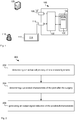
- Fig. 1 illustrates a computer system 100 for assisting surgery of a joint.
- the computer system 100 comprises a processor 102 connected to a program memory 104, a data memory 106, a communication port 108 and a user port 110.
- the program memory 104 is a non-transitory computer readable medium, such as a hard drive, a solid state disk or CD-ROM.
- Software that is, an executable program stored on program memory 104 causes the processor 102 to perform the method in Fig. 2 , that is, processor 102 determines a mechanical property of the ligaments and a predicted post-operative characteristic, such as laxity of the joint.
- Laxity may be defined by a set of angles and/or movement of the joint under different loads and poses.
- the term "determining a laxity" refers to calculating one or more values that are indicative of the laxity.
- the processor 102 may then store the laxity on data store 106, such as on RAM or a processor register. Processor 102 may also send the determined laxity via communication port 108 to a server, such as patient management database.
- a server such as patient management database.
- the processor 102 may receive data, such as X-ray image data , from data memory 106 as well as from the communications port 108 and the user port 110, which is connected to a display 112 that shows a visual representation 114 of the image data to a surgeon 116 or other user or operator.
- processor 102 receives image data from an X-ray, magnetic resonance imaging (MRI) or computer tomography (CT) imaging device via communications port 108, such as by using a Wi-Fi network according to IEEE 802.11.
- the Wi-Fi network may be a decentralised ad-hoc network, such that no dedicated management infrastructure, such as a router, is required or a centralised network with a router or access point managing the network.
- communications port 108 and user port 110 are shown as distinct entities, it is to be understood that any kind of data port may be used to receive data, such as a network connection, a memory interface, a pin of the chip package of processor 102, or logical ports, such as IP sockets or parameters of functions stored on program memory 104 and executed by processor 102. These parameters may be stored on data memory 106 and may be handled by-value or by-reference, that is, as a pointer, in the source code.
- the processor 102 may receive data through all these interfaces, which includes memory access of volatile memory, such as cache or RAM, or non-volatile memory, such as an optical disk drive, hard disk drive, storage server or cloud storage.
- volatile memory such as cache or RAM
- non-volatile memory such as an optical disk drive, hard disk drive, storage server or cloud storage.
- the computer system 100 may further be implemented within a cloud computing environment, such as a managed group of interconnected servers hosting a dynamic number of virtual machines.
- any receiving step may be preceded by the processor 102 determining or computing the data that is later received.
- the processor 102 determines measurement data and stores the measurement data in data memory 106, such as RAM or a processor register.
- the processor 102 requests the data from the data memory 106, such as by providing a read signal together with a memory address.
- the data memory 106 provides the data as a voltage signal on a physical bit line and the processor 102 receives the measurement data via a memory interface.
- nodes, edges, graphs, solutions, variables, surgery plans, dimensions, locations and the like refer to data structures, which are physically stored on data memory 106 or processed by processor 102. Further, for the sake of brevity when reference is made to particular variable names, such as "predicted characteristic” or “spatial parameter of the surgery” this is to be understood to refer to values of variables stored as physical data in computer system 100.
- the joint comprises a kinematic system of two bones, such as the tibia and femur in the example of knee surgery or hip and femur in the example of hip surgery.
- the kinematic system may comprise more than two bones including the patella, for example.
- Processor 102 commences performing method 200 by determining a mechanical property of one or more ligaments associated with the joint. For example, processor determines a stiffness and a length value, which may be a free length, a reference length or a taut length. This calculation is based on measurement data indicative of a movement of the bones relative to each other under multiple mechanical loads. In one example, processor 102 determines the measurement data based on multiple X-ray images, which are also referred to as 'first' images, and an MRI image, that is also referred to as 'second' image.
- 'image' may refer to a two-dimensional image, such in X-ray image stored on data memory 106 in the form of a two-dimensional pixel matrix comprising one intensity value for each pixel in the case of a grey scale image.
- 'image' may also refer to a three-dimensional image comprising multiple two-dimensional images, such as an MRI or CT image which a surgeon can peruse on a two-dimensional screen by selecting different depth values and different viewing angles.
- Two-dimensional and three-dimensional images may be stored on data memory 106 as multiple image values, such as in a two-dimensional or three-dimensional pixel matrix.
- the images are stored in a parameterised representation, such as a spline representation and processor 102 generates a two-dimensional view on a screen by interpolation based on the spline parameters.
- Fig. 3a illustrates an X-ray image 300 of a knee joint in an unloaded state, that is, the patient is lying without externally applied forces.
- X-ray image 300 shows the femur 302 the tibia 304 and an absolute reference 306 that was place next to the knee when taking the X-ray image.
- Processor 102 detects the edges of the femur 302 and tibia 304 using a Sobel operator, for example. In another example, processor 102 performs a method for 2D-3D image registration as described in the following publications:
- Fig. 3b illustrates an X-ray image 350 of the knee joint in a loaded state.
- the patient is standing on one leg on a step and a weight is attached to the foot of the other leg that is relaxed and hangs off the step.
- processor 102 detects the edges of femur 302 and tibia 304 and determines a minimum distance 352 in millimetres between them.
- Processor 102 can then calculate the change in distance from 308 to 352 as well as rotation difference, which is indicative of the relative movement of the femur 302 in relation to the tibia 304 or vice versa.
- processor 102 can determine these mechanical characteristics based on a mechanical model and the measured distances 308 and 352.
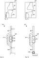
- Fig. 4a illustrates a simplified mechanical model 400 of the knee in the unloaded state related to X-ray image 300 while Fig. 4b illustrates the mechanical model of the knee in a loaded state related to X-ray image 350.
- the mechanical model 400 comprises an upper rod 402 representing the femur 302 and a lower rod 404 representing the tibia 304.
- the two rods 402 and 404 are mechanically coupled by a joint 402 that allows rotation with one degree of rotational freedom as indicated by arrows 406 and 408 to model the flexion and extension of a human knee.
- Joint 402 also allows translational movement with one degree of freedom as indicated by arrows 410 and 412 to represent stretching of the knee under load.
- the translational movement 410 and 412 is restricted by a spring 414, that is, spring 414 pulls the upper rod 402 towards the lower rod 404 with a force that increases with the distance between the upper rod 402 and the lower rod 404.
- Fig. 4b illustrates the mechanical model 400 of the knee as in Fig. 4a but now the mechanical model is under load as shown in X-ray image of Fig 3b.
- Fig. 4b illustrates a weight 452 that is attached to the lower rod 404.
- the weight 452 there is translational movement of the lower rod 404 in relation to the upper rod 402 against the pull force of spring 414 resulting in a distance 452 in the joint 402.
- the distance in the joint is zero in the unloaded case in Fig. 4a for simplicity.
- F is the force applied by weight 452, such as 5 kg
- x is the measured movement 452, both of which are stored on data memory 106.
- Figs. 4a and 4b relate to determining the stiffness of only a single ligament
- processor 102 determines the stiffness of multiple ligaments.
- the knee can be separated into three physiological anatomical compartments: the patellofemoral compartment, the medial compartment, and the lateral compartment.
- the lateral compartment is bounded medially by the anterior cruciate ligament, laterally by the lateral capsular ligament, the ilio-tibial tract, and the fibula lateral ligament and posteriorly by the arcuate complex and the posterior capsule.
- These structures are all supported by the iliotibial band, the poplitius muscle, the biceps muscle and an extension of the semimembranosus muscle called the oblique popliteal ligament.
- processor 102 may determine the movement 352 for multiple different mechanical loads.
- Each ligament generates another unknown in a linear system of equations based on the above formula and each measurement of a different load generates an observation.
- the number of different loads is at least the number of ligaments.
- the accuracy can be increased by having each linear equation linearly independent from the other equations. Therefore, the load may be applied to the knee at different flexion angles of the knee such that different ligaments are stretched at different angles.
- the measurement data may comprise data generated by a stress device that applies the different mechanical loads to the knee.
- the stress device is a Telos stress device by Austin & Associates, Inc./Telos GmbH. It is noted that other devices may also be used to generate the measurement data.
- processor determines 204 a predicted characteristic of the joint after the surgery, such as predicted post-op laxity. This step is based on a spatial parameter of the surgery and based on the previously determined mechanical property of the one or more ligaments.
- the surgery may comprise the insertion of an implant, which likely affects the three-dimensional geometries of the joint.
- the cut angle of the tibia on which the implant is mounted is an important spatial parameter that affects the angles of the knee.
- Other spatial parameters relate to the geometry of the particular implant. This geometry may be retrieved from an implant library that stores the geometries of a wide range of available implants.
- Processor 102 then generates 206 an output signal indicative of the predicted characteristic to assist the surgery.
- the output signal is a display to be shown to the surgeon on a computer screen.
- the display may comprise numbers representing the determined varus/valgus at different stress test or may comprises a graphical indication of predicted post-operative laxity, such as curves of varus/valgus at applied moments to the model at different flexion angles. This informs the surgeon on whether the planned parameters of the operation are satisfactory or whether the cut angle for the implant should be adjusted, for example.
- the surgeon enters a desired laxity or the planning software determines a desired laxity based on particular activities that the patient wants to perform after the surgery. For example, kneeling down would be easier with a less tight knee, that is, more laxity, while playing tennis would be easier with a tighter knee, that is, less laxity.
- the output signal is then indicative of whether the predicted characteristic corresponds to the desired characteristic, such as by highlighting in red colour the values for relative movement or angles when processor 102 applies forces to the mechanical model as described above.
- the output signal may also be a data signal representing a report of the predicted characteristic of the joint after surgery. The report may also include the pre-operative characteristic.
- Figs. 7a, 7b and 7c illustrate laxity envelopes for femoral internal/external rotation 702, femoral varus/valgus 704 and anterior/posterior laxity 706, respectively, over a range of flexion from 0 to 120 degrees.
- Implant System Details may be Femoral Component: Omni Apex Right CR Femur Size 5 Tibial Component: Omni Apex Tibial Tray Size 6 Tibial Insert: Omni Apex CR Insert Size 5 10mm Patella Button: Omni Apex Patella Button Size 35 8mm
- Figs. 8a to 8f graphically illustrate the predicted characteristic of the knee after surgery in the form of rendered images of the mechanical model of the knee for the load of 6Nm applied to the model.
- Figs. 8a to 8c relate to full extension
- Figs. 8d to 8f relate to a fully flexed knee.
- the surgeon can clearly see that a varus torque of 6Nm results in a predicted varus of 3 degrees at full extension (see Fig. 8a and a varus of 4 degrees at full flexion (see Fig. 8d ).
- the unloaded knee is balanced at full extension, that is has 0 degrees varus/valgus (see Fig. 8b ) but has a 1 degree varus at full flexion (see Fig. 8e ).
- Fig. 9 illustrates a more detailed version of method 200 in the form of a flow chart 900.
- the flow chart 900 may also be implemented by corresponding software modules.
- the central module is a ligaments optimisation module 902 that optimises the mechanical properties of the ligaments to best fit to the observations of the movement of the bones under different mechanical loads.
- ligaments optimisation module 902 receives patient geometry data from a patient geometry data module 904.
- the ligaments optimisation module 902 further receives measurement data, such as the three-dimensional position of bones in X-rays under different load conditions from pose estimation module 906.
- the knee optimisation module 902 may start from a starting position, such as 0° flexion, neutral moves the knee to the position obtained from pose estimation.
- Processor 102 calculates ligament properties, stiffness and free length values within bounds so that the knee can reach to its desired position.
- Figs. 15a and 15b illustrate an example of a navigation system that provides different measurement data, such as varus/valgus at different flexion angles.
Landscapes
- Health & Medical Sciences (AREA)
- Engineering & Computer Science (AREA)
- Life Sciences & Earth Sciences (AREA)
- Medical Informatics (AREA)
- Public Health (AREA)
- Biomedical Technology (AREA)
- General Health & Medical Sciences (AREA)
- Surgery (AREA)
- Veterinary Medicine (AREA)
- Animal Behavior & Ethology (AREA)
- Heart & Thoracic Surgery (AREA)
- Nuclear Medicine, Radiotherapy & Molecular Imaging (AREA)
- Molecular Biology (AREA)
- Pathology (AREA)
- Physics & Mathematics (AREA)
- High Energy & Nuclear Physics (AREA)
- Biophysics (AREA)
- Radiology & Medical Imaging (AREA)
- Optics & Photonics (AREA)
- Orthopedic Medicine & Surgery (AREA)
- Data Mining & Analysis (AREA)
- Primary Health Care (AREA)
- Epidemiology (AREA)
- Databases & Information Systems (AREA)
- Oral & Maxillofacial Surgery (AREA)
- Robotics (AREA)
- Pulmonology (AREA)
- Theoretical Computer Science (AREA)
- Physiology (AREA)
- Computer Vision & Pattern Recognition (AREA)
- Transplantation (AREA)
- Dentistry (AREA)
- Physical Education & Sports Medicine (AREA)
- Cardiology (AREA)
- Vascular Medicine (AREA)
- Apparatus For Radiation Diagnosis (AREA)
- Prostheses (AREA)
Description
- The present application claims priority from
Australian Provisional Patent Application No 2015903060 filed on 31 July 2015 - This disclosure relates to methods and systems to assist in surgery of a joint.
- The success of orthopaedic surgery often depends on a spatial parameter of the surgery, such as the angle at which a bone is cut in order to attach an implant, such as an artificial joint. For example, the cutting angle of the tibia for a knee replacement influences the degree of varus/valgus, which is also known as bow-legged/cross-legged.
- In many cases, surgeons have the experience and knowledge to decide on a cutting angle or use computers to calculate an optimal cutting angle. However, in many cases the actual outcome of the surgery is not optimal, that is, the patient is less mobile after the surgery than what would be possible with a different cutting angle. S. Martelli et al: "Total knee arthroplasty kinematics", THE JOURNAL OF ARTHROPLASTY, vol. 13, no. 2, 1 February 1998, pages 145-155, discloses computer simulations for intraoperative testing of the passive kinematics of knee prostheses based on an anatomic model of the reconstructed joint, represented in the sagittal plane.
- Any discussion of documents, acts, materials, devices, articles or the like which has been included in the present specification is not to be taken as an admission that any or all of these matters form part of the prior art base or were common general knowledge in the field relevant to the present disclosure as it existed before the priority date of each claim of this application.
- Throughout this specification the word "comprise", or variations such as "comprises" or "comprising", will be understood to imply the inclusion of a stated element, integer or step, or group of elements, integers or steps, but not the exclusion of any other element, integer or step, or group of elements, integers or steps.
- The present invention is defined by the independent claims. Advantageous embodiments are described by the dependent claims.
- Since the predicted characteristic of the joint is determined based on the mechanical property of the ligaments, the prediction is more accurate than other methods that rely on only bone geometries to predict a surgery outcome. This is an advantage because the surgeon can plan the surgery more accurately, which also means the patient outcome will be improved. As a result, treated patients have increased quality of live as they are able to perform more activities due to the improved surgery outcome.
- Optional features described of any aspect of method, computer readable medium or computer system, where appropriate, similarly apply to the other aspects also described here.
- An example will be described with reference to:
-
Fig. 1 illustrates a computer system for assisting surgery of a joint. -
Fig. 2 illustrates a method for assisting surgery of a joint. -
Fig. 3a illustrates an X-ray image of a knee joint in an unloaded state. -
Fig. 3b illustrates an X-ray image of the knee joint in a loaded state. -
Fig. 4a illustrates a simplified mechanical model of the knee in the unloaded state. -
Fig. 4b illustrates the mechanical model of the knee in the loaded state. -
Fig. 5 illustrates a mechanical model of a knee under three different mechanical loads. -
Fig. 6 illustrates the mechanical model of the knee under four further different mechanical loads. -
Figs. 7a, 7b and7c illustrate respective laxity envelopes. -
Figs. 8a to 8f graphically illustrate predicted characteristic of the knee after surgery. -
Fig. 9 illustrates another method for assisting surgery of a joint. -
Figs. 10a to 10d illustrate registration between X-ray image data and a mechanical model. -
Fig. 11 illustrates an initialisation of an iterative landmark-to-ray 2D-3D registration. -
Fig. 12 illustrates finding 3D point pairs for the iterative landmark-to-ray 2D-3D registration. -
Fig 13 illustrates an example of the optimization model. -
Fig. 14 illustrates a post-op laxity assessment simulation display. -
Figs. 15a and 15b illustrate an example of a navigation system. -
Fig. 1 illustrates acomputer system 100 for assisting surgery of a joint. Thecomputer system 100 comprises aprocessor 102 connected to aprogram memory 104, adata memory 106, acommunication port 108 and auser port 110. Theprogram memory 104 is a non-transitory computer readable medium, such as a hard drive, a solid state disk or CD-ROM. Software, that is, an executable program stored onprogram memory 104 causes theprocessor 102 to perform the method inFig. 2 , that is,processor 102 determines a mechanical property of the ligaments and a predicted post-operative characteristic, such as laxity of the joint. Laxity may be defined by a set of angles and/or movement of the joint under different loads and poses. The term "determining a laxity" refers to calculating one or more values that are indicative of the laxity. - The
processor 102 may then store the laxity ondata store 106, such as on RAM or a processor register.Processor 102 may also send the determined laxity viacommunication port 108 to a server, such as patient management database. - The
processor 102 may receive data, such as X-ray image data , fromdata memory 106 as well as from thecommunications port 108 and theuser port 110, which is connected to adisplay 112 that shows avisual representation 114 of the image data to asurgeon 116 or other user or operator. In one example,processor 102 receives image data from an X-ray, magnetic resonance imaging (MRI) or computer tomography (CT) imaging device viacommunications port 108, such as by using a Wi-Fi network according to IEEE 802.11. The Wi-Fi network may be a decentralised ad-hoc network, such that no dedicated management infrastructure, such as a router, is required or a centralised network with a router or access point managing the network. - Although
communications port 108 anduser port 110 are shown as distinct entities, it is to be understood that any kind of data port may be used to receive data, such as a network connection, a memory interface, a pin of the chip package ofprocessor 102, or logical ports, such as IP sockets or parameters of functions stored onprogram memory 104 and executed byprocessor 102. These parameters may be stored ondata memory 106 and may be handled by-value or by-reference, that is, as a pointer, in the source code. - The
processor 102 may receive data through all these interfaces, which includes memory access of volatile memory, such as cache or RAM, or non-volatile memory, such as an optical disk drive, hard disk drive, storage server or cloud storage. Thecomputer system 100 may further be implemented within a cloud computing environment, such as a managed group of interconnected servers hosting a dynamic number of virtual machines. - It is to be understood that any receiving step may be preceded by the
processor 102 determining or computing the data that is later received. For example, theprocessor 102 determines measurement data and stores the measurement data indata memory 106, such as RAM or a processor register. Theprocessor 102 then requests the data from thedata memory 106, such as by providing a read signal together with a memory address. Thedata memory 106 provides the data as a voltage signal on a physical bit line and theprocessor 102 receives the measurement data via a memory interface. - It is to be understood that throughout this disclosure unless stated otherwise, nodes, edges, graphs, solutions, variables, surgery plans, dimensions, locations and the like refer to data structures, which are physically stored on
data memory 106 or processed byprocessor 102. Further, for the sake of brevity when reference is made to particular variable names, such as "predicted characteristic" or "spatial parameter of the surgery" this is to be understood to refer to values of variables stored as physical data incomputer system 100. -
Fig. 2 illustrates amethod 200 as performed byprocessor 102 for assisting surgery of a joint.Fig. 2 is to be understood as a blueprint for the software program and may be implemented step-by-step, such that each step inFig. 2 is represented by a function in a programming language, such as C++ or Java. The resulting source code is then compiled and stored as computer executable instructions onprogram memory 104. - The joint comprises a kinematic system of two bones, such as the tibia and femur in the example of knee surgery or hip and femur in the example of hip surgery. The kinematic system may comprise more than two bones including the patella, for example.
-
Processor 102 commences performingmethod 200 by determining a mechanical property of one or more ligaments associated with the joint. For example, processor determines a stiffness and a length value, which may be a free length, a reference length or a taut length. This calculation is based on measurement data indicative of a movement of the bones relative to each other under multiple mechanical loads. In one example,processor 102 determines the measurement data based on multiple X-ray images, which are also referred to as 'first' images, and an MRI image, that is also referred to as 'second' image. - It is to be understood that 'image' may refer to a two-dimensional image, such in X-ray image stored on
data memory 106 in the form of a two-dimensional pixel matrix comprising one intensity value for each pixel in the case of a grey scale image. However, 'image' may also refer to a three-dimensional image comprising multiple two-dimensional images, such as an MRI or CT image which a surgeon can peruse on a two-dimensional screen by selecting different depth values and different viewing angles. Two-dimensional and three-dimensional images may be stored ondata memory 106 as multiple image values, such as in a two-dimensional or three-dimensional pixel matrix. In other examples, the images are stored in a parameterised representation, such as a spline representation andprocessor 102 generates a two-dimensional view on a screen by interpolation based on the spline parameters. -
Fig. 3a illustrates anX-ray image 300 of a knee joint in an unloaded state, that is, the patient is lying without externally applied forces.X-ray image 300 shows thefemur 302 thetibia 304 and anabsolute reference 306 that was place next to the knee when taking the X-ray image.Processor 102 detects the edges of thefemur 302 andtibia 304 using a Sobel operator, for example. In another example,processor 102 performs a method for 2D-3D image registration as described in the following publications: - Youngjun Kim, Kang-Il Kim, Jin hyeok Choi, Kunwoo Lee, "Novel methods for 3D postoperative analysis of total knee arthroplasty using 2D―3D image registration", Clinical Biomechanics 26 (2011) 384-391;
- Guoyan Zheng, Xuan Zhang "Computer assisted determination of acetabular cup orientation using 2D―3D image registration", International Journal of Computer Assisted Radiology and Surgery, September 2010, ; and
- Guoyan Zheng, Simon Steppacher, Xuan Zhang, Moritz Tannast, "Precise Estimation of Postoperative Cup Alignment from Single Standard X-Ray Radiograph with Gonadal Shielding", Medical Image Computing and Computer-Assisted Intervention ― MICCAI 2007, Lecture Notes in Computer Science Volume 4792, 2007, pp 951-959.
-
Processor 102 then determines aminimum distance 308 between thefemur 302 andtibia 304 as a number of image pixels.Processor 102 can then detect theabsolute scale 306 to transform the number of image pixels into an absolute measurement in millimetres, for example. -
Fig. 3b illustrates anX-ray image 350 of the knee joint in a loaded state. In this example, the patient is standing on one leg on a step and a weight is attached to the foot of the other leg that is relaxed and hangs off the step. As can be seen inFig. 3b there has been movement of thefemur 302 and thetibia 304 relative to each other under the two different mechanical loads, that is, a movement betweenFig. 3a and Fig. 3b . Againprocessor 102 detects the edges offemur 302 andtibia 304 and determines aminimum distance 352 in millimetres between them.Processor 102 can then calculate the change in distance from 308 to 352 as well as rotation difference, which is indicative of the relative movement of thefemur 302 in relation to thetibia 304 or vice versa. - Since the
distance 352 under load depends on the mechanical characteristics of the ligaments,processor 102 can determine these mechanical characteristics based on a mechanical model and the measureddistances -
Fig. 4a illustrates a simplifiedmechanical model 400 of the knee in the unloaded state related toX-ray image 300 whileFig. 4b illustrates the mechanical model of the knee in a loaded state related toX-ray image 350. In this example, themechanical model 400 comprises anupper rod 402 representing thefemur 302 and alower rod 404 representing thetibia 304. The tworods arrows arrows translational movement spring 414, that is,spring 414 pulls theupper rod 402 towards thelower rod 404 with a force that increases with the distance between theupper rod 402 and thelower rod 404. -
Fig. 4b illustrates themechanical model 400 of the knee as inFig. 4a but now the mechanical model is under load as shown in X-ray image ofFig 3b. Fig. 4b illustrates aweight 452 that is attached to thelower rod 404. As a result of theweight 452 there is translational movement of thelower rod 404 in relation to theupper rod 402 against the pull force ofspring 414 resulting in adistance 452 in the joint 402. In this example, it is assumed that the distance in the joint is zero in the unloaded case inFig. 4a for simplicity. - The force F applied by
spring 414 with spring constant k at length x is F = ―kx , which can be re-arranged to
weight 452, such as 5 kg, and x is the measuredmovement 452, both of which are stored ondata memory 106. As a result,processor 102 can determine the spring constant k, which is also referred to as the stiffness value of the ligament. By setting the value for F to zero,processor 102 can also calculate the free length, which is the result for x given the determined spring constant k and F=0. - While the example of
Figs. 4a and 4b relates to determining the stiffness of only a single ligament, inother examples processor 102 determines the stiffness of multiple ligaments. For example, the knee can be separated into three physiological anatomical compartments: the patellofemoral compartment, the medial compartment, and the lateral compartment. The lateral compartment is bounded medially by the anterior cruciate ligament, laterally by the lateral capsular ligament, the ilio-tibial tract, and the fibula lateral ligament and posteriorly by the arcuate complex and the posterior capsule. These structures are all supported by the iliotibial band, the poplitius muscle, the biceps muscle and an extension of the semimembranosus muscle called the oblique popliteal ligament. - The medial compartment is bounded medially by the deep third of the mid-capsular ligament, the medial collateral ligament, and the posterior oblique ligament and laterally by the posterior cruciate ligament. Anteriorly, these compartments have extensions of the medial capsule as well as patellotibial and patellofemoral expansions, as well as the patella tendon.
- Since each ligament may have a different stiffness value and free-length value,
processor 102 may determine themovement 352 for multiple different mechanical loads. Each ligament generates another unknown in a linear system of equations based on the above formula and each measurement of a different load generates an observation. Preferably, the number of different loads is at least the number of ligaments. Further, the accuracy can be increased by having each linear equation linearly independent from the other equations. Therefore, the load may be applied to the knee at different flexion angles of the knee such that different ligaments are stretched at different angles. - The measurement data may comprise data generated by a stress device that applies the different mechanical loads to the knee. In one example, the stress device is a Telos stress device by Austin & Associates, Inc./Telos GmbH. It is noted that other devices may also be used to generate the measurement data.
- Before processing the X-ray images of the loaded knee,
processor 102 may determine the attachment locations of each ligament to the bone and the shape and size of the bones to refine themechanical model 400. For example, theprocessor 102 may process an MRI scan of the bone. The ligaments are clearly visible on MRI but hardly visible on an X-ray image. However, it is difficult to apply mechanical force to the knee while taking an MRI scan due to the relatively long time the MRI scan takes and due to the strong magnetic field of the MRI scanner. Therefore, the MRI is only captured once to define the static characteristic of the joint, including the 3D geometries and landmarks from which to measure the movement, such as medial and lateral condyles. Then, multiple X-rays are captured at different loads and flexion angles. - Instead of the
single distance measurement 352 ofFig. 3b , the measurement data may include multiple measurements for each mechanical load, such as distances from medial and lateral condyles to the tibia to define vargus and valgus.Processor 102 may further calculate a pre-operative characteristic of the knee, such as pre-op laxity. - Returning back to
Fig. 2 , after the mechanical properties of the ligaments are determined, processor determines 204 a predicted characteristic of the joint after the surgery, such as predicted post-op laxity. This step is based on a spatial parameter of the surgery and based on the previously determined mechanical property of the one or more ligaments. The surgery may comprise the insertion of an implant, which likely affects the three-dimensional geometries of the joint. In particular, the cut angle of the tibia on which the implant is mounted is an important spatial parameter that affects the angles of the knee. Other spatial parameters relate to the geometry of the particular implant. This geometry may be retrieved from an implant library that stores the geometries of a wide range of available implants.Processor 102 receives the data indicative of the planned cut angle and the geometries of the implant. Based on this data and the mechanical characteristic of the ligaments,processor 102 calculates a predicted characteristic of the knee after the surgery. That is,processor 102 applies the same loads as above on the mechanical model considering the determined ligament properties but now for a changed geometry as a result of the planned surgery. For example,processor 102 determines the post-operative varus/valgus values and post-operative laxity of the knee joint using spring constants k and new geometries. -
Processor 102 then generates 206 an output signal indicative of the predicted characteristic to assist the surgery. In one example, the output signal is a display to be shown to the surgeon on a computer screen. The display may comprise numbers representing the determined varus/valgus at different stress test or may comprises a graphical indication of predicted post-operative laxity, such as curves of varus/valgus at applied moments to the model at different flexion angles. This informs the surgeon on whether the planned parameters of the operation are satisfactory or whether the cut angle for the implant should be adjusted, for example. - For example, the surgeon may perform a surgical technique called gap balancing where the surgeon cuts the tibia surface first then distracts the joint to find balance. Then the femoral component alignment, particularly rotation, is planned accordingly to achieve that balance. However, the definition of balance may differ between surgeons and may be subjective. By measuring the applied force or pressure during the joint distraction,
processor 102 can generate an output signal that objectively indicates to the surgeon how to balance the knee based on the mechanical simulation model. - In another example, the output signal to assist the surgery is a feedback signal to a planning software that automatically optimises the spatial parameters, such as iteratively adjusts the cut angle until the output signal is indicative of a desired laxity. In that example, the surgeon may enter an intended cut angle which is received by the
processor 102 as a pre-defined value of the spatial parameter of the surgery. If the output signal generated byprocessor 120 is indicative of an unsatisfactory laxity, the planning software adjusts the pre-define value to optimise the laxity. - In yet another example, the surgeon enters a desired laxity or the planning software determines a desired laxity based on particular activities that the patient wants to perform after the surgery. For example, kneeling down would be easier with a less tight knee, that is, more laxity, while playing tennis would be easier with a tighter knee, that is, less laxity. The output signal is then indicative of whether the predicted characteristic corresponds to the desired characteristic, such as by highlighting in red colour the values for relative movement or angles when
processor 102 applies forces to the mechanical model as described above. The output signal may also be a data signal representing a report of the predicted characteristic of the joint after surgery. The report may also include the pre-operative characteristic. -
Fig. 5 illustrates a mechanical model of a knee under three different mechanical loads, that is, while one leg is hanging 502, when the knee is weight bearing 504 and undervarus stress 506.Fig. 6 illustrates the mechanical model of the knee under four further different mechanical loads, that is,valgus stress 602,anterior draw test 604,posterior draw test 606 andextension laxity test 608. -
Figs. 7a, 7b and7c illustrate laxity envelopes for femoral internal/external rotation 702, femoral varus/valgus 704 and anterior/posterior laxity 706, respectively, over a range of flexion from 0 to 120 degrees. - In one example, the ligament laxity order is:
Ligaments Tight by percentage LCL 20 % MCL 10% PCL - - Implant System Details may be
Femoral Component: Omni Apex Right CR Femur Size 5Tibial Component: Omni Apex Tibial Tray Size 6 Tibial Insert: Omni Apex CR Insert Size 5 10mmPatella Button: Omni Apex Patella Button Size 35 8mm - Component Placement Information may be:
Femoral Component Tibial Component TibioFemoral Alignment Sagittal: 4.0° Flexion 3.0° Slope Coronal: 0.0° Varus 0.0° Varus 0.0° Varus Transverse: 0.0° Internal 0.0° Internal 0.0° Internal AP 2mm anterior from Best fit to resected position PCA tibia geometry SI position Level with distal condyle 11mm cut from medial plateau ML position Best fit to resected geometry Best fit to resected geometry -
Figs. 8a to 8f graphically illustrate the predicted characteristic of the knee after surgery in the form of rendered images of the mechanical model of the knee for the load of 6Nm applied to the model.Figs. 8a to 8c relate to full extension, whileFigs. 8d to 8f relate to a fully flexed knee. For example, the surgeon can clearly see that a varus torque of 6Nm results in a predicted varus of 3 degrees at full extension (seeFig. 8a and a varus of 4 degrees at full flexion (seeFig. 8d ). Further, the unloaded knee is balanced at full extension, that is has 0 degrees varus/valgus (seeFig. 8b ) but has a 1 degree varus at full flexion (seeFig. 8e ). -
Fig. 9 illustrates a more detailed version ofmethod 200 in the form of aflow chart 900. Theflow chart 900 may also be implemented by corresponding software modules. The central module is aligaments optimisation module 902 that optimises the mechanical properties of the ligaments to best fit to the observations of the movement of the bones under different mechanical loads. For these calculationsligaments optimisation module 902 receives patient geometry data from a patientgeometry data module 904. Theligaments optimisation module 902 further receives measurement data, such as the three-dimensional position of bones in X-rays under different load conditions frompose estimation module 906. Thepose estimation module 906, in turn, receives the X-ray data fromX-ray data module 908, such as X-ray images at different functional positions including one or more of: Varus at 0° flexion, Valgus at 0° flexion, Anterior draw at 0° flexion, Posterior draw 0° flexion, Weight bearing and Hyperextend knee. -
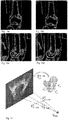
Figs. 10a to 10d illustrate the registration step between the X-ray image data as schematically shown inFigs. 3a and 3b and the mechanical model inFigs. 4a and 4b . In this example, the image data is registered to a femur model. The X-ray image data in darker shading, while model outline is shown in brighter shading. This registration step may be part of the steps for determining the measurement data indicative of a movement of the bones relative to each other under multiple mechanical loads.Figs. 10a and 10c illustrate the image data and the model before registration whileFigs. 10b and 10d illustrate the image data and the model after registration where the femur model matches the X-ray image data. -
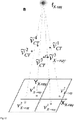
Fig. 11 illustrates an initialisation of an iterative landmark-to-ray 2D-3D registration, whileFig. 12 illustrates finding 3D point pairs for the iterative landmark-to-ray 2D-3D registration. - The
knee optimisation module 902 may start from a starting position, such as 0° flexion, neutral moves the knee to the position obtained from pose estimation.Processor 102 calculates ligament properties, stiffness and free length values within bounds so that the knee can reach to its desired position. -
Fig 13 illustrates an example of the optimization model that is optimised to determine the mechanical characteristic of the ligaments. In this example, from X-ray image data the joint is at 5° varus when flexed at 20°. The ligament optimization model may iteratively change ligament stiffness and free length value to achieve equilibrium at that position. The determined ligament properties to be used later are then the values at the equilibrium. - The ligament properties together with implants position and
geometry 910 and patient geometry data frompatient geometry module 904 are forwarded to a post-operativelaxity prediction module 912, which determines apost-operative laxity 912, such as varus at extension, valgus at extension, varus at 90° flexion and valgus at 90° flexion and agraphical representation 914 of these characteristics. These results are sent to areporting module 916, which generates the report as described above in relation toFigs. 5 to 8 . -
Fig. 14 illustrates an example of a post-op laxityassessment simulation display 1400 comprising a three-dimensionalgraphical representation 1402 of the knee, which may be animated to indicate angle of flexion or angle of valgus/varus, for example.Display 1400 further comprises afirst graph 1404 indicating thetorque 1406 applied to the mechanical model and the resulting valgus/varus angle 1408.Display 1400 also comprises a second graph 1410 indicating the resulting simulated ligament forces 1412 of each of the multiple ligaments in the knee over the valgus/varus angle 1414, where each line in second graph 1410 represents a different ligament.Display 1400 may be provided to a surgeon during the planning phase of the surgery, such as on a screen in the consulting room of the surgeon or on a screen in theatre. - While some examples herein relate to image data that represents the movement of the bones relative to each other, it is to be understood that different measurement data may also be used which does not fall under the scope of the claimed invention, such as a direct measurement of the movement of the bones under load by measuring the positions of landmarks that are accessible through the skin or even during surgery, such as by measuring the distances from the medial or lateral condyle using a surgical calliper without the use of X-ray or other images. These methods therefore provide contact-based data since these methods are based on contacting the bones either directly or through the skin.
- Further, the measurement data used to determine the mechanical properties of the ligaments may be reported computer assisted surgery data, such as kinematics between bones captured by a navigation system the as surgeon assesses the joint with various movements.
-
Figs. 15a and 15b illustrate an example of a navigation system that provides different measurement data, such as varus/valgus at different flexion angles. - It will be appreciated by persons skilled in the art that numerous variations and/or modifications may be made to the specific embodiments without departing from the scope as defined in the claims.
- It should be understood that the techniques of the present disclosure might be implemented using a variety of technologies. For example, the methods described herein may be implemented by a series of computer executable instructions residing on a suitable computer readable medium. Suitable computer readable media may include volatile (e.g. RAM) and/or non-volatile (e.g. ROM, disk) memory, carrier waves and transmission media. Exemplary carrier waves may take the form of electrical, electromagnetic or optical signals conveying digital data steams along a local network or a publically accessible network such as the internet.
- It should also be understood that, unless specifically stated otherwise as apparent from the following discussion, it is appreciated that throughout the description, discussions utilizing terms such as "estimating" or "processing" or "computing" or "calculating", "optimizing" or "determining" or "displaying" or "maximising" or the like, refer to the action and processes of a computer system, or similar electronic computing device, that processes and transforms data represented as physical (electronic) quantities within the computer system's registers and memories into other data similarly represented as physical quantities within the computer system memories or registers or other such information storage, transmission or display devices.
- The present embodiments are, therefore, to be considered in all respects as illustrative and not restrictive.
Claims (10)
- A computer-implemented method (200) for assisting surgery of a joint (402) comprising a kinematic system of two bones (402, 404), the joint being a knee, the method comprising:determining a predicted characteristic of the joint after the surgery; wherein determining the predicted characteristic of the joint after the surgery is based on a spatial parameter of the surgery and based on a mechanical property of the one or more ligaments, the predicted characteristic being a predicted laxity of the joint, the mechanical property comprising a stiffness value or a length value or both of the one or more ligaments;
andgenerating an output signal indicative of the predicted characteristic to assist the surgery;characterised by:determining the mechanical property of one or more ligaments (414) associated with the joint based on measurement data indicative of a movement of the bones relative to each other under multiple mechanical loads (452);determining the measurement data based on multiple first images, each of the multiple first images representing a position of the bones relative to each other under the respective mechanical load. - The computer-implemented method of claim 1, wherein the kinematic system comprises three or more bones.
- The computer-implemented method of claim 1 or 2, wherein the spatial parameter of the surgery is a cutting angle for attaching an implant.
- The computer-implemented method of any one of the preceding claims, further comprising using the output signal to optimise the spatial parameter of the surgery and optimising the spatial parameter of the surgery comprises adjusting a pre-defined value of the spatial parameter of the surgery.
- The computer-implemented method of any one of the preceding claims, wherein determining the mechanical property comprises determining the mechanical property based on a spatial configuration of the joint.
- The computer-implemented method of claim 5, further comprising determining the spatial configuration of the joint based on a 3D scan of the joint.
- The computer-implemented method of claim 6, wherein determining the spatial configuration of the joint comprises determining the spatial configuration of the joint based on a CT scan or MRI scan or both.
- The computer-implemented method of any one of the preceding claims, further comprising receiving input data indicative of a desired characteristic of the joint, wherein generating an output signal comprises generating an output signal that is indicative of a correspondence between the desired characteristic and the predicted characteristic.
- The computer-implemented method of any one of the preceding claims, wherein determining the mechanical property of the one or more ligaments comprises determining the mechanical property of the one or more ligaments based on measurement data indicative of the movement of the bones relative to each other under multiple angles between the two bones.
- A computer system (100) for assisting surgery of a joint (402) comprising a kinematic system of two bones (402, 404), the joint being a knee, the computer system comprising:a processor configured to:determine a predicted characteristic of the joint after the surgery;wherein determining the predicted characteristic of the joint after the surgery is based on a spatial parameter of the surgery and based on a mechanical property of the one or more ligaments, the predicted characteristic being a predicted laxity of the joint, the mechanical property comprising a stiffness value or a length value or both of the one or more ligaments;
andan output port for an output signal indicative of the predicted characteristic to assist the surgery;characterised in thatthe computer system further comprisesan input port (108) configured to receive multiple first images;and the processor is further configured to determine the mechanical property of one or more ligaments (414)
associated with the joint based on measurement data indicative of a movement of the bones relative to each other under multiple mechanical loads (452);to determine the measurement data based on the multiple first images, each of the multiple first images representing a position of the bones relative to each other under the respective mechanical load.
Applications Claiming Priority (2)
| Application Number | Priority Date | Filing Date | Title |
|---|---|---|---|
| AU2015903060A AU2015903060A0 (en) | 2015-07-31 | Post-operative prediction | |
| PCT/AU2016/050661 WO2017020069A1 (en) | 2015-07-31 | 2016-07-25 | Post-operative prediction |
Publications (3)
| Publication Number | Publication Date |
|---|---|
| EP3328301A1 EP3328301A1 (en) | 2018-06-06 |
| EP3328301A4 EP3328301A4 (en) | 2019-03-27 |
| EP3328301B1 true EP3328301B1 (en) | 2021-11-10 |
Family
ID=57942132
Family Applications (1)
| Application Number | Title | Priority Date | Filing Date |
|---|---|---|---|
| EP16831963.0A Active EP3328301B1 (en) | 2015-07-31 | 2016-07-25 | Post-operative prediction |
Country Status (4)
| Country | Link |
|---|---|
| US (1) | US11096721B2 (en) |
| EP (1) | EP3328301B1 (en) |
| AU (1) | AU2016302388B2 (en) |
| WO (1) | WO2017020069A1 (en) |
Families Citing this family (7)
| Publication number | Priority date | Publication date | Assignee | Title |
|---|---|---|---|---|
| EP3595567A1 (en) * | 2017-03-14 | 2020-01-22 | Smith & Nephew, Inc. | Systems and methods for measuring bone joint laxity |
| KR101886650B1 (en) * | 2017-04-13 | 2018-08-10 | 주식회사 티제이씨라이프 | Material Properties Evaluaion Method for Ligaments in the Tibiofemoral |
| JP6958261B2 (en) * | 2017-11-09 | 2021-11-02 | コニカミノルタ株式会社 | Paper loading device and image forming system |
| RU2748271C1 (en) * | 2020-07-02 | 2021-05-21 | Общество с ограниченной ответственностью "МОТУС" | Apparatus for determining stiffness of patellar ligamentous apparatus and method of use thereof |
| AU2021371301A1 (en) | 2020-10-30 | 2023-06-15 | Mako Surgical Corp. | Robotic surgical system with cut selection logic |
| EP4262605A1 (en) | 2020-12-15 | 2023-10-25 | MAKO Surgical Corp. | Dynamic gap capture and flexion widget |
| USD1044829S1 (en) | 2021-07-29 | 2024-10-01 | Mako Surgical Corp. | Display screen or portion thereof with graphical user interface |
Family Cites Families (10)
| Publication number | Priority date | Publication date | Assignee | Title |
|---|---|---|---|---|
| US6161080A (en) * | 1997-11-17 | 2000-12-12 | The Trustees Of Columbia University In The City Of New York | Three dimensional multibody modeling of anatomical joints |
| AU2002346407A1 (en) * | 2001-11-14 | 2003-05-26 | University Of British Columbia | Methods and systems for intraoperative measurement of soft tissue constraints in computer aided total joint replacement surgery |
| US20030153978A1 (en) | 2002-02-08 | 2003-08-14 | Whiteside Biomechanics, Inc. | Apparatus and method of ligament balancing and component fit check in total knee arthroplasty |
| US7490012B2 (en) * | 2002-05-29 | 2009-02-10 | Japan Science And Technology Agency | Body dynamics calculation method, body dynamics model and model data thereof, and body-model generation method |
| JP2008526427A (en) * | 2005-01-18 | 2008-07-24 | スミス アンド ネフュー インコーポレーテッド | Computer-aided ligament balancing in knee arthroplasty |
| US8078440B2 (en) * | 2008-09-19 | 2011-12-13 | Smith & Nephew, Inc. | Operatively tuning implants for increased performance |
| US8983813B2 (en) * | 2011-02-25 | 2015-03-17 | Optimized Ortho Pty Ltd | Computer-implemented method, a computing device and a computer readable storage medium for providing alignment information data for the alignment of an orthopaedic implant for a joint of a patient |
| BR112014001295A2 (en) * | 2011-07-20 | 2017-02-21 | Smith & Nephew Inc | systems and methods for optimizing the fit of an implant to anatomy |
| US9788975B2 (en) | 2011-10-28 | 2017-10-17 | Zimmer, Inc. | Method of estimating soft tissue balance for knee arthroplasty |
| WO2014145267A1 (en) * | 2013-03-15 | 2014-09-18 | Conformis, Inc. | Kinematic and parameterized modeling for patient-adapted implants, tools, and surgical procedures |
-
2016
- 2016-07-25 EP EP16831963.0A patent/EP3328301B1/en active Active
- 2016-07-25 WO PCT/AU2016/050661 patent/WO2017020069A1/en not_active Ceased
- 2016-07-25 AU AU2016302388A patent/AU2016302388B2/en active Active
- 2016-07-25 US US15/747,317 patent/US11096721B2/en active Active
Non-Patent Citations (1)
| Title |
|---|
| J C KENNEDY ET AL: "Medial and anterior instability of the knee. An anatomical and clinical study using stress machines", THE JOURNAL OF BONE & JOINT SURGERY. 53(7), 31 October 1971 (1971-10-31), pages 1257 - 1270, XP055656307, Retrieved from the Internet <URL:http://www.ncbi.nlm.nih.gov/pubmed/5170981> [retrieved on 20200109] * |
Also Published As
| Publication number | Publication date |
|---|---|
| EP3328301A1 (en) | 2018-06-06 |
| WO2017020069A1 (en) | 2017-02-09 |
| EP3328301A4 (en) | 2019-03-27 |
| AU2016302388B2 (en) | 2021-07-29 |
| US20180214180A1 (en) | 2018-08-02 |
| US11096721B2 (en) | 2021-08-24 |
| AU2016302388A1 (en) | 2018-02-15 |
Similar Documents
| Publication | Publication Date | Title |
|---|---|---|
| US11096721B2 (en) | Post-operative prediction | |
| Fregly et al. | Theoretical accuracy of model-based shape matching for measuring natural knee kinematics with single-plane fluoroscopy | |
| Jamali et al. | Do small changes in rotation affect measurements of lower extremity limb alignment? | |
| CN107847275B (en) | System and method for positioning soft tissue for preoperative planning | |
| Burssens et al. | Reliability and correlation analysis of computed methods to convert conventional 2D radiological hindfoot measurements to a 3D setting using weightbearing CT | |
| Tarassoli et al. | Long leg radiographs underestimate the degree of constitutional varus limb alignment and joint line obliquity in comparison with computed tomography: a radiographic study | |
| Jarrett et al. | Axial oblique CT to assess femoral anteversion | |
| Guggenberger et al. | Assessment of lower limb length and alignment by biplanar linear radiography: comparison with supine CT and upright full-length radiography | |
| Lansdown et al. | Variations in knee kinematics after ACL injury and after reconstruction are correlated with bone shape differences | |
| WO2020056443A1 (en) | Method of surgery | |
| Hernandez-Vaquero et al. | Computer-assisted surgery improves rotational positioning of the femoral component but not the tibial component in total knee arthroplasty | |
| Mathon et al. | Healthy middle-aged Asian and Caucasian populations present with large intra-and inter-individual variations of lower limb torsion | |
| Oussedik et al. | Is femoral component rotation in a TKA reliably guided by the functional flexion axis? | |
| Wright et al. | Strong correlation between the morphology of the proximal femur and the geometry of the distal femoral trochlea | |
| Thorhauer et al. | Validation of a method for combining biplanar radiography and magnetic resonance imaging to estimate knee cartilage contact | |
| Dunbar et al. | Longitudinal migration and inducible displacement of the Mobility Total Ankle System: radiostereometry in 23 patients with 2 years of follow-up | |
| Lebailly et al. | Semi-automated stereoradiographic upper limb 3D reconstructions using a combined parametric and statistical model: a preliminary study | |
| Cavaignac et al. | Experimental study of an original radiographic view for diagnosis of cam-type anterior femoroacetabular impingement | |
| Morvan et al. | Femoral torsion: impact of femur position on CT and stereoradiography measurements | |
| Suter et al. | Comparison of measurements of the glenopolar angle in 3D CT reconstructions of the scapula and 2D plain radiographic views | |
| Koh et al. | Gender differences exist in rotational anatomy of the distal femur in osteoarthritic knees using MRI | |
| Arora et al. | The role of pre-operative templating in primary total knee replacement | |
| Bartels et al. | Computed tomography-based joint locations affect calculation of joint moments during gait when compared to scaling approaches | |
| Dandu et al. | Future directions in patellofemoral imaging and 3D modeling | |
| Lee et al. | Computer-aided automatic measurement of leg length on full leg radiographs |
Legal Events
| Date | Code | Title | Description |
|---|---|---|---|
| STAA | Information on the status of an ep patent application or granted ep patent |
Free format text: STATUS: THE INTERNATIONAL PUBLICATION HAS BEEN MADE |
|
| PUAI | Public reference made under article 153(3) epc to a published international application that has entered the european phase |
Free format text: ORIGINAL CODE: 0009012 |
|
| STAA | Information on the status of an ep patent application or granted ep patent |
Free format text: STATUS: REQUEST FOR EXAMINATION WAS MADE |
|
| 17P | Request for examination filed |
Effective date: 20180221 |
|
| AK | Designated contracting states |
Kind code of ref document: A1 Designated state(s): AL AT BE BG CH CY CZ DE DK EE ES FI FR GB GR HR HU IE IS IT LI LT LU LV MC MK MT NL NO PL PT RO RS SE SI SK SM TR |
|
| AX | Request for extension of the european patent |
Extension state: BA ME |
|
| DAV | Request for validation of the european patent (deleted) | ||
| DAX | Request for extension of the european patent (deleted) | ||
| A4 | Supplementary search report drawn up and despatched |
Effective date: 20190225 |
|
| RIC1 | Information provided on ipc code assigned before grant |
Ipc: A61B 34/10 20160101ALI20190219BHEP Ipc: G16H 50/50 20180101ALI20190219BHEP Ipc: A61B 6/00 20060101ALI20190219BHEP Ipc: A61B 17/56 20060101AFI20190219BHEP |
|
| STAA | Information on the status of an ep patent application or granted ep patent |
Free format text: STATUS: EXAMINATION IS IN PROGRESS |
|
| 17Q | First examination report despatched |
Effective date: 20200124 |
|
| REG | Reference to a national code |
Ref country code: DE Ref legal event code: R079 Ref document number: 602016066130 Country of ref document: DE Free format text: PREVIOUS MAIN CLASS: A61B0017560000 Ipc: A61B0034100000 |
|
| GRAP | Despatch of communication of intention to grant a patent |
Free format text: ORIGINAL CODE: EPIDOSNIGR1 |
|
| STAA | Information on the status of an ep patent application or granted ep patent |
Free format text: STATUS: GRANT OF PATENT IS INTENDED |
|
| RIC1 | Information provided on ipc code assigned before grant |
Ipc: A61B 34/10 20160101AFI20210511BHEP Ipc: G16H 50/50 20180101ALI20210511BHEP Ipc: A61B 6/00 20060101ALI20210511BHEP |
|
| INTG | Intention to grant announced |
Effective date: 20210602 |
|
| GRAS | Grant fee paid |
Free format text: ORIGINAL CODE: EPIDOSNIGR3 |
|
| GRAA | (expected) grant |
Free format text: ORIGINAL CODE: 0009210 |
|
| STAA | Information on the status of an ep patent application or granted ep patent |
Free format text: STATUS: THE PATENT HAS BEEN GRANTED |
|
| AK | Designated contracting states |
Kind code of ref document: B1 Designated state(s): AL AT BE BG CH CY CZ DE DK EE ES FI FR GB GR HR HU IE IS IT LI LT LU LV MC MK MT NL NO PL PT RO RS SE SI SK SM TR |
|
| REG | Reference to a national code |
Ref country code: GB Ref legal event code: FG4D |
|
| REG | Reference to a national code |
Ref country code: AT Ref legal event code: REF Ref document number: 1445342 Country of ref document: AT Kind code of ref document: T Effective date: 20211115 Ref country code: CH Ref legal event code: EP |
|
| REG | Reference to a national code |
Ref country code: DE Ref legal event code: R096 Ref document number: 602016066130 Country of ref document: DE |
|
| REG | Reference to a national code |
Ref country code: IE Ref legal event code: FG4D |
|
| REG | Reference to a national code |
Ref country code: LT Ref legal event code: MG9D |
|
| REG | Reference to a national code |
Ref country code: NL Ref legal event code: MP Effective date: 20211110 |
|
| REG | Reference to a national code |
Ref country code: AT Ref legal event code: MK05 Ref document number: 1445342 Country of ref document: AT Kind code of ref document: T Effective date: 20211110 |
|
| PG25 | Lapsed in a contracting state [announced via postgrant information from national office to epo] |
Ref country code: RS Free format text: LAPSE BECAUSE OF FAILURE TO SUBMIT A TRANSLATION OF THE DESCRIPTION OR TO PAY THE FEE WITHIN THE PRESCRIBED TIME-LIMIT Effective date: 20211110 Ref country code: LT Free format text: LAPSE BECAUSE OF FAILURE TO SUBMIT A TRANSLATION OF THE DESCRIPTION OR TO PAY THE FEE WITHIN THE PRESCRIBED TIME-LIMIT Effective date: 20211110 Ref country code: FI Free format text: LAPSE BECAUSE OF FAILURE TO SUBMIT A TRANSLATION OF THE DESCRIPTION OR TO PAY THE FEE WITHIN THE PRESCRIBED TIME-LIMIT Effective date: 20211110 Ref country code: BG Free format text: LAPSE BECAUSE OF FAILURE TO SUBMIT A TRANSLATION OF THE DESCRIPTION OR TO PAY THE FEE WITHIN THE PRESCRIBED TIME-LIMIT Effective date: 20220210 Ref country code: AT Free format text: LAPSE BECAUSE OF FAILURE TO SUBMIT A TRANSLATION OF THE DESCRIPTION OR TO PAY THE FEE WITHIN THE PRESCRIBED TIME-LIMIT Effective date: 20211110 |
|
| PG25 | Lapsed in a contracting state [announced via postgrant information from national office to epo] |
Ref country code: IS Free format text: LAPSE BECAUSE OF FAILURE TO SUBMIT A TRANSLATION OF THE DESCRIPTION OR TO PAY THE FEE WITHIN THE PRESCRIBED TIME-LIMIT Effective date: 20220310 Ref country code: SE Free format text: LAPSE BECAUSE OF FAILURE TO SUBMIT A TRANSLATION OF THE DESCRIPTION OR TO PAY THE FEE WITHIN THE PRESCRIBED TIME-LIMIT Effective date: 20211110 Ref country code: PT Free format text: LAPSE BECAUSE OF FAILURE TO SUBMIT A TRANSLATION OF THE DESCRIPTION OR TO PAY THE FEE WITHIN THE PRESCRIBED TIME-LIMIT Effective date: 20220310 Ref country code: PL Free format text: LAPSE BECAUSE OF FAILURE TO SUBMIT A TRANSLATION OF THE DESCRIPTION OR TO PAY THE FEE WITHIN THE PRESCRIBED TIME-LIMIT Effective date: 20211110 Ref country code: NO Free format text: LAPSE BECAUSE OF FAILURE TO SUBMIT A TRANSLATION OF THE DESCRIPTION OR TO PAY THE FEE WITHIN THE PRESCRIBED TIME-LIMIT Effective date: 20220210 Ref country code: NL Free format text: LAPSE BECAUSE OF FAILURE TO SUBMIT A TRANSLATION OF THE DESCRIPTION OR TO PAY THE FEE WITHIN THE PRESCRIBED TIME-LIMIT Effective date: 20211110 Ref country code: LV Free format text: LAPSE BECAUSE OF FAILURE TO SUBMIT A TRANSLATION OF THE DESCRIPTION OR TO PAY THE FEE WITHIN THE PRESCRIBED TIME-LIMIT Effective date: 20211110 Ref country code: HR Free format text: LAPSE BECAUSE OF FAILURE TO SUBMIT A TRANSLATION OF THE DESCRIPTION OR TO PAY THE FEE WITHIN THE PRESCRIBED TIME-LIMIT Effective date: 20211110 Ref country code: GR Free format text: LAPSE BECAUSE OF FAILURE TO SUBMIT A TRANSLATION OF THE DESCRIPTION OR TO PAY THE FEE WITHIN THE PRESCRIBED TIME-LIMIT Effective date: 20220211 Ref country code: ES Free format text: LAPSE BECAUSE OF FAILURE TO SUBMIT A TRANSLATION OF THE DESCRIPTION OR TO PAY THE FEE WITHIN THE PRESCRIBED TIME-LIMIT Effective date: 20211110 |
|
| PG25 | Lapsed in a contracting state [announced via postgrant information from national office to epo] |
Ref country code: SM Free format text: LAPSE BECAUSE OF FAILURE TO SUBMIT A TRANSLATION OF THE DESCRIPTION OR TO PAY THE FEE WITHIN THE PRESCRIBED TIME-LIMIT Effective date: 20211110 Ref country code: SK Free format text: LAPSE BECAUSE OF FAILURE TO SUBMIT A TRANSLATION OF THE DESCRIPTION OR TO PAY THE FEE WITHIN THE PRESCRIBED TIME-LIMIT Effective date: 20211110 Ref country code: RO Free format text: LAPSE BECAUSE OF FAILURE TO SUBMIT A TRANSLATION OF THE DESCRIPTION OR TO PAY THE FEE WITHIN THE PRESCRIBED TIME-LIMIT Effective date: 20211110 Ref country code: EE Free format text: LAPSE BECAUSE OF FAILURE TO SUBMIT A TRANSLATION OF THE DESCRIPTION OR TO PAY THE FEE WITHIN THE PRESCRIBED TIME-LIMIT Effective date: 20211110 Ref country code: DK Free format text: LAPSE BECAUSE OF FAILURE TO SUBMIT A TRANSLATION OF THE DESCRIPTION OR TO PAY THE FEE WITHIN THE PRESCRIBED TIME-LIMIT Effective date: 20211110 Ref country code: CZ Free format text: LAPSE BECAUSE OF FAILURE TO SUBMIT A TRANSLATION OF THE DESCRIPTION OR TO PAY THE FEE WITHIN THE PRESCRIBED TIME-LIMIT Effective date: 20211110 |
|
| REG | Reference to a national code |
Ref country code: DE Ref legal event code: R097 Ref document number: 602016066130 Country of ref document: DE |
|
| PLBE | No opposition filed within time limit |
Free format text: ORIGINAL CODE: 0009261 |
|
| STAA | Information on the status of an ep patent application or granted ep patent |
Free format text: STATUS: NO OPPOSITION FILED WITHIN TIME LIMIT |
|
| 26N | No opposition filed |
Effective date: 20220811 |
|
| PG25 | Lapsed in a contracting state [announced via postgrant information from national office to epo] |
Ref country code: AL Free format text: LAPSE BECAUSE OF FAILURE TO SUBMIT A TRANSLATION OF THE DESCRIPTION OR TO PAY THE FEE WITHIN THE PRESCRIBED TIME-LIMIT Effective date: 20211110 |
|
| PG25 | Lapsed in a contracting state [announced via postgrant information from national office to epo] |
Ref country code: SI Free format text: LAPSE BECAUSE OF FAILURE TO SUBMIT A TRANSLATION OF THE DESCRIPTION OR TO PAY THE FEE WITHIN THE PRESCRIBED TIME-LIMIT Effective date: 20211110 |
|
| PG25 | Lapsed in a contracting state [announced via postgrant information from national office to epo] |
Ref country code: MC Free format text: LAPSE BECAUSE OF FAILURE TO SUBMIT A TRANSLATION OF THE DESCRIPTION OR TO PAY THE FEE WITHIN THE PRESCRIBED TIME-LIMIT Effective date: 20211110 |
|
| REG | Reference to a national code |
Ref country code: BE Ref legal event code: MM Effective date: 20220731 |
|
| PG25 | Lapsed in a contracting state [announced via postgrant information from national office to epo] |
Ref country code: LU Free format text: LAPSE BECAUSE OF NON-PAYMENT OF DUE FEES Effective date: 20220725 |
|
| PG25 | Lapsed in a contracting state [announced via postgrant information from national office to epo] |
Ref country code: IT Free format text: LAPSE BECAUSE OF FAILURE TO SUBMIT A TRANSLATION OF THE DESCRIPTION OR TO PAY THE FEE WITHIN THE PRESCRIBED TIME-LIMIT Effective date: 20211110 Ref country code: BE Free format text: LAPSE BECAUSE OF NON-PAYMENT OF DUE FEES Effective date: 20220731 |
|
| P01 | Opt-out of the competence of the unified patent court (upc) registered |
Effective date: 20230516 |
|
| PG25 | Lapsed in a contracting state [announced via postgrant information from national office to epo] |
Ref country code: IE Free format text: LAPSE BECAUSE OF NON-PAYMENT OF DUE FEES Effective date: 20220725 |
|
| PG25 | Lapsed in a contracting state [announced via postgrant information from national office to epo] |
Ref country code: HU Free format text: LAPSE BECAUSE OF FAILURE TO SUBMIT A TRANSLATION OF THE DESCRIPTION OR TO PAY THE FEE WITHIN THE PRESCRIBED TIME-LIMIT; INVALID AB INITIO Effective date: 20160725 |
|
| PG25 | Lapsed in a contracting state [announced via postgrant information from national office to epo] |
Ref country code: MK Free format text: LAPSE BECAUSE OF FAILURE TO SUBMIT A TRANSLATION OF THE DESCRIPTION OR TO PAY THE FEE WITHIN THE PRESCRIBED TIME-LIMIT Effective date: 20211110 Ref country code: CY Free format text: LAPSE BECAUSE OF FAILURE TO SUBMIT A TRANSLATION OF THE DESCRIPTION OR TO PAY THE FEE WITHIN THE PRESCRIBED TIME-LIMIT Effective date: 20211110 |
|
| PG25 | Lapsed in a contracting state [announced via postgrant information from national office to epo] |
Ref country code: MT Free format text: LAPSE BECAUSE OF FAILURE TO SUBMIT A TRANSLATION OF THE DESCRIPTION OR TO PAY THE FEE WITHIN THE PRESCRIBED TIME-LIMIT Effective date: 20211110 |
|
| REG | Reference to a national code |
Ref country code: DE Ref legal event code: R081 Ref document number: 602016066130 Country of ref document: DE Owner name: KICO KNEE INNOVATION COMPANY PTY LIMITED, FREN, AU Free format text: FORMER OWNER: 360 KNEE SYSTEMS PTY LTD., PYMBLE, NEW SOUTH WALES, AU |
|
| PGFP | Annual fee paid to national office [announced via postgrant information from national office to epo] |
Ref country code: DE Payment date: 20250729 Year of fee payment: 10 |
|
| PGFP | Annual fee paid to national office [announced via postgrant information from national office to epo] |
Ref country code: GB Payment date: 20250728 Year of fee payment: 10 |
|
| PGFP | Annual fee paid to national office [announced via postgrant information from national office to epo] |
Ref country code: FR Payment date: 20250725 Year of fee payment: 10 |
|
| PGFP | Annual fee paid to national office [announced via postgrant information from national office to epo] |
Ref country code: CH Payment date: 20250801 Year of fee payment: 10 |
|
| REG | Reference to a national code |
Ref country code: GB Ref legal event code: 732E Free format text: REGISTERED BETWEEN 20251009 AND 20251015 |
|
| PG25 | Lapsed in a contracting state [announced via postgrant information from national office to epo] |
Ref country code: TR Free format text: LAPSE BECAUSE OF FAILURE TO SUBMIT A TRANSLATION OF THE DESCRIPTION OR TO PAY THE FEE WITHIN THE PRESCRIBED TIME-LIMIT Effective date: 20211110 |
|
| REG | Reference to a national code |
Ref country code: CH Ref legal event code: R14 Free format text: ST27 STATUS EVENT CODE: U-0-0-R10-R14 (AS PROVIDED BY THE NATIONAL OFFICE) Effective date: 20260422 |