EP3327882A1 - Spark plug - Google Patents
Spark plug Download PDFInfo
- Publication number
- EP3327882A1 EP3327882A1 EP17204164.2A EP17204164A EP3327882A1 EP 3327882 A1 EP3327882 A1 EP 3327882A1 EP 17204164 A EP17204164 A EP 17204164A EP 3327882 A1 EP3327882 A1 EP 3327882A1
- Authority
- EP
- European Patent Office
- Prior art keywords
- gasket
- seat portion
- spark plug
- arithmetic average
- average roughness
- Prior art date
- Legal status (The legal status is an assumption and is not a legal conclusion. Google has not performed a legal analysis and makes no representation as to the accuracy of the status listed.)
- Withdrawn
Links
Images

Classifications
-
- H—ELECTRICITY
- H01—ELECTRIC ELEMENTS
- H01T—SPARK GAPS; OVERVOLTAGE ARRESTERS USING SPARK GAPS; SPARKING PLUGS; CORONA DEVICES; GENERATING IONS TO BE INTRODUCED INTO NON-ENCLOSED GASES
- H01T13/00—Sparking plugs
- H01T13/20—Sparking plugs characterised by features of the electrodes or insulation
-
- H—ELECTRICITY
- H01—ELECTRIC ELEMENTS
- H01T—SPARK GAPS; OVERVOLTAGE ARRESTERS USING SPARK GAPS; SPARKING PLUGS; CORONA DEVICES; GENERATING IONS TO BE INTRODUCED INTO NON-ENCLOSED GASES
- H01T13/00—Sparking plugs
- H01T13/02—Details
-
- H—ELECTRICITY
- H01—ELECTRIC ELEMENTS
- H01T—SPARK GAPS; OVERVOLTAGE ARRESTERS USING SPARK GAPS; SPARKING PLUGS; CORONA DEVICES; GENERATING IONS TO BE INTRODUCED INTO NON-ENCLOSED GASES
- H01T13/00—Sparking plugs
- H01T13/02—Details
- H01T13/08—Mounting, fixing or sealing of sparking plugs, e.g. in combustion chamber
-
- H—ELECTRICITY
- H01—ELECTRIC ELEMENTS
- H01T—SPARK GAPS; OVERVOLTAGE ARRESTERS USING SPARK GAPS; SPARKING PLUGS; CORONA DEVICES; GENERATING IONS TO BE INTRODUCED INTO NON-ENCLOSED GASES
- H01T13/00—Sparking plugs
- H01T13/40—Sparking plugs structurally combined with other devices
-
- H—ELECTRICITY
- H01—ELECTRIC ELEMENTS
- H01T—SPARK GAPS; OVERVOLTAGE ARRESTERS USING SPARK GAPS; SPARKING PLUGS; CORONA DEVICES; GENERATING IONS TO BE INTRODUCED INTO NON-ENCLOSED GASES
- H01T13/00—Sparking plugs
- H01T13/02—Details
- H01T13/16—Means for dissipating heat
Definitions
- the present invention relates to a spark plug and particularly relates to a spark plug that allows improvement of thermal resistance.
- a spark plug is mounted to an engine by a screw portion of a metal shell holding an insulator being joined into a screw hole of the engine.
- a gasket is disposed between the engine and a seat portion, of the metal shell, which projects radially outward (see, for example, Patent Document 1).
- Patent Document 1 is Japanese Patent Application Laid-Open ( kokai ) No. 2013-149623 .
- the present invention has been conceived to meet the above-described need, and an object of the invention is to provide a spark plug that allows improvement of heat transfer property and improvement of thermal resistance.
- a cylindrical metal shell extending in an axis direction has a seat portion projecting radially outward, and an annular gasket is disposed so as to oppose a front end surface of the seat portion.
- a value G/S obtained by dividing an arithmetic average roughness G of a first surface, of the gasket, which comes into contact with the front end surface of the seat portion by an arithmetic average roughness S of the front end surface of the seat portion satisfies 0.5 ⁇ G/S ⁇ 2.0.
- the arithmetic average roughness G is not more than 0.16 ⁇ m.
- a spark plug including a cylindrical metal shell extending in an axis direction and including a seat portion projecting radially outward, with the seat portion having a front end surface with a first arithmetic average roughness S.
- the spark plug further includes an annular gasket configured to oppose the front end surface of the seat portion, the gasket having a first surface in contact with the front end surface of the seat portion and a second surface opposite the first surface, the first surface of the gasket having a second arithmetic average roughness G.
- the second arithmetic average roughness G of the first surface of the gasket is not more than 0.16 ⁇ m, and a value G/S is obtained by dividing the second arithmetic average roughness G of the first surface of the gasket by the first arithmetic average roughness S of the front end surface of the seat portion, such that the value G/S satisfies 0.5 ⁇ G/S ⁇ 2.0. Also, an average of an area of the second surface of the gasket and an area of the first surface of the gasket is not more than 280 mm 2 .
- the gasket is formed into a solid plate shape, a cross-sectional area, of the gasket, which contributes to thermal conduction can be ensured. Therefore, in addition to the effect of the first aspect of the present invention, an effect of improving thermal conductivity of the gasket and improving thermal resistance can be obtained.
- the gasket may have flat first and second surfaces.
- the gasket may be a flat annular gasket, and the annular part is preferably solid, i.e. not hollow.
- the gasket has an outer diameter of not more than 15 mm, an effect of reducing the diameter of the spark plug and ensuring thermal resistance can be obtained in addition to the effect of the first aspect or the second aspect of the present invention.
- FIG. 1 is a cross-sectional view of one side of a spark plug 10 according to an embodiment of the present invention.
- the lower side on the surface of the drawing sheet is referred to as a front side of the spark plug 10
- the upper side on the surface of the drawing sheet is referred to as a rear side of the spark plug 10.
- the spark plug 10 includes an insulator 11 and a metal shell 15.
- the insulator 11 is a member made of alumina or the like which is excellent in mechanical property and insulation property at a high temperature, and has an axial hole 12 that penetrates therethrough along an axis O.
- a center electrode 13 is disposed on the front side of the axial hole 12.
- the center electrode 13 is a rod-shaped member which extends along the axis O and in which a core material made of copper or a core material that contains copper as a main component is covered with nickel or a nickel-based alloy.
- the center electrode 13 is held by the insulator 11 and has a front end that is exposed from the axial hole 12.
- a metal terminal 14 is a rod-shaped member to which a high-voltage cable (not shown) is connected, and is made of a metal material (e.g., low-carbon steel or the like) having conductivity.
- the metal terminal 14 has a front end side portion pressed in the axial hole 12, and is fixed to a rear end portion of the insulator 11.
- the metal shell 15 is crimped and fixed, around the outer circumference of the insulator 11, to the front end side portion thereof which is distant from the rear end of the insulator 11 by a predetermined distance in the axis O direction such that an insulation distance between the metal shell 15 and the metal terminal 14 is ensured.
- the metal shell 15 is a substantially cylindrical member made of a metal material (e.g., low-carbon steel or the like) having conductivity.
- the metal shell 15 includes an annular seat portion 16 that is flange-shaped and projects radially outward, and a screw portion 18 that is formed on the outer circumferential surface of the metal shell 15 in a portion forward of the seat portion 16.
- the metal shell 15 is fixed by the screw portion 18 being fastened into a screw hole of an engine 30 (cylinder head).
- a gasket 20 (described later) is disposed between a front end surface 17 of the seat portion 16 and the engine 30.
- a ground electrode 19 is a metal member (e.g., made of a nickel-based alloy) that is joined to the front end of the metal shell 15.
- the ground electrode 19 is formed in a bar shape, and has a front end side portion that is bent to oppose the center electrode 13.
- a spark gap is formed between the ground electrode 19 and the center electrode 13.
- the gasket 20 is an annular member and includes a first surface 21 that comes into contact with the front end surface 17 of the seat portion 16 and a second surface 22 that opposes the engine 30.
- the gasket 20 is held between the seat portion 16 and the engine 30, and prevents leakage of combustion gas from the screw hole of the engine 30.
- the gasket 20 is made of a metal and contains copper as a main component, and contains elements such as nickel, tin, and phosphorus as well as copper.
- the gasket 20 is not limited to the gasket that is made of a metal and that contains copper as a main component, and, as a matter of course, another publicly known material such as mild steel, pure iron, stainless steel, aluminum, titanium, or the like may be adopted.
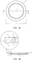
- FIG. 2A is a plan view of the gasket 20, and FIG. 2B is a cross-sectional view of the gasket 20, including the axis O, taken along the line IIb-IIb shown in FIG. 2A .
- the gasket 20 is formed into a solid plate shape. Solid means stuffed and having no hollow portion, and specifically means that the gasket is not formed by a plate material being bent.
- the gasket 20 includes the annular first surface 21, the annular second surface 22 that is disposed on the side opposite to the first surface 21 side, an outer peripheral side surface 23 that connects between the second surface 22 and the first surface 21 on the outer peripheral side of the gasket 20, a projection portion 24 that projects radially inward from a portion in the vicinity of the first surface 21, and an inner peripheral side surface 26 that connects between the projection portion 24 and the second surface 22.
- the projection portion 24 is engaged with a rear end portion of the screw portion 18 (see FIG. 1 ) to regulate movement of the gasket 20 in an axis direction with respect to the screw portion 18.
- An inner peripheral surface 25 of the projection portion 24 is tilted with respect to the axis O.
- the first surface 21 comes into contact with the front end surface 17 of the seat portion 16 (see FIG. 1 ), and is adjacent to the outer peripheral side surface 23 and the inner peripheral surface 25.
- the second surface 22 comes into contact with the engine 30 (see FIG. 1 ), and is adjacent to the outer peripheral side surface 23 and the inner peripheral side surface 26.
- the average obtained by adding the area of the first surface 21 and the area of the second surface 22 and dividing the total area of the two surfaces by two, is set to be not more than 280 mm 2 .
- the gasket 20 has an outer diameter D of not more than 15 mm.
- an arithmetic average roughness Ra (hereinafter referred to as "G") of the first surface 21 of the gasket 20 is set to be not more than 0.16 ⁇ m, and a value G/S, obtained by dividing the arithmetic average roughness G by an arithmetic average roughness Ra (hereinafter referred to as "S") of the front end surface 17 of the seat portion 16, satisfies 0.5 ⁇ G/S ⁇ 2.0.
- the surface roughness refers to the surface roughness, of each of the seat portion 16 and the gasket 20, obtained before the spark plug 10 is mounted to the engine 30.
- the arithmetic average roughness G and the arithmetic average roughness S are each calculated on the basis of JIS B0601 (2013 edition).
- the arithmetic average roughness G is an average of values, of arithmetic average roughness, at eight locations at which the first surface 21 can be divided into eight equal portions in a circumferential direction.
- the arithmetic average roughness S is an average of values, of arithmetic average roughness, at eight locations at which the front end surface 17 can be divided into eight equal portions in a circumferential direction.
- the arithmetic average roughness of the first surface 21 is measured in the back side portion of the second surface 22 (portion other than the projection portion 24).
- the gasket 20 is formed into a solid plate shape, a cross-sectional area of the gasket 20 orthogonal to the axis O can be ensured. Since the cross-sectional area of the gasket 20 contributes to thermal conduction, thermal conductivity of the gasket 20 can be improved and thermal resistance of the spark plug 10 can be improved.
- the diameter of the spark plug 10 can be reduced.
- the gasket 20 has the outer diameter D of not more than 15 mm.
- heat transfer property so-called heat conduction
- the diameter of the spark plug 10 can be reduced while thermal resistance of the spark plug 10 can be ensured.
- the screw portion 18 of the spark plug 10 was fastened into a nut that was made of an aluminum alloy and that was supported by an arm, and the gasket 20 was held between the seat portion 16 of the spark plug 10 and the nut.
- a test was performed to evaluate the heat transfer property of the gasket 20 by heating, by means of a burner, the ground electrode 19 projecting from the nut and measuring a difference in temperature between the seat portion 16 and the gasket 20.
- a test method will be described.
- the nominal diameter of the screw portion 18 was 10 mm.
- the gasket 20 was an annular solid plate material made of a metal that contains copper as a main component, and the dimensions were such that the outer diameter was 14.8 mm (tolerance +0.3 mm, -0 mm), the inner diameter was 9.9 mm (tolerance +0.1 mm, -0 mm), and the thickness was 1.5 mm (tolerance ⁇ 0.05 mm).
- the outer diameter of the seat portion 16 of the spark plug 10 was made greater than the outer diameter of the gasket 20.
- the dimensions of the nut into which the screw portion 18 was fastened were such that the width across flats (opposed sides of a hexagon) was 30 mm (tolerance +0 mm, -0.5 mm) and the thickness was about 10 mm.
- Various spark plugs 10 (samples 1 to 23) were prepared such that the size and material were the same among the samples of the spark plug 10 (including the gasket 20), and only the surface roughness of each of the seat portion 16 and the gasket 20 was different among the samples.
- the spark plugs 10 (samples 24 to 29), in each of which the nominal diameter of the screw portion 18 was 12 mm, were prepared and the spark plugs 10 (samples 30 to 33), in each of which the nominal diameter of the screw portion 18 was 14 mm, were prepared.
- the gaskets 20 in samples 24 to 33 were each formed also into an annular solid plate material made of a metal that contains copper as a main component. In each of the samples 1 to 33, the average, obtained by adding the area of the first surface 21 of the gasket 20 and the area of the second surface 22 of the gasket 20 and dividing the total area of the two surfaces by two, was obtained.
- the arithmetic average roughness Ra of the front end surface 17 of the seat portion 16 was measured by means of a contact-type surface roughness measuring machine on the basis of JIS B0601 (2013 edition).
- the arithmetic average roughness is an average of values, of arithmetic average roughness, at eight locations at which each of the front end surface 17, the first surface 21, and the second surface 22 can be divided into eight equal portions in a circumferential direction.
- a roughness component of each measurement location was measured.
- the measurement length at one measurement location was about 800 ⁇ m.
- the screw portion 18 of the spark plug 10 was screwed into the nut supported by the arm with a torque of 15 N.m, and the spark plug 10 was mounted in a state where the gasket 20 was held between the seat portion 16 and the nut.
- the front end of the ground electrode 19 was heated in flame of a burner, such that the temperature of the ground electrode 19 in the spark plug 10 became 900°C, and the temperature of the center of a side surface of the seat portion 16 and the temperature of the center of the outer peripheral side surface 23 of the gasket 20 were measured by means of a thermocouple after elapse of five minutes from the start of the heating.
- Table 1 indicates the average of the area of the first surface 21 and the area of the second surface 22, the arithmetic average roughness of the front end surface 17 of the seat portion 16, the arithmetic average roughness of the first surface 21 of the gasket 20, and the arithmetic average roughness of the second surface 22 of the gasket 20, the temperature of the center of the side surface of the seat portion 16, the temperature of the center of the outer peripheral side surface 23 of the gasket 20, the difference in temperature between the two centers, and evaluations.
- the present invention has been described based on the embodiments, the present invention is not limited to the above-described embodiments at all. It can be easily understood that various modifications can be devised without departing from the gist of the present invention.
- the shape, dimensions, and the like of the gasket 20 are not limited to the above-described ones and can be set as appropriate.
- the present invention is not necessarily limited thereto.
- a gasket in which a plate material is bent to provide a hollow portion thereinside such that elasticity of the gasket is increased may be adopted. This is because, since compatibility between the gasket and the seat portion 16 can be made good by setting the surface roughness of the seat portion 16 side surface of the gasket and the surface roughness of the front end surface 17 of the seat portion 16, the heat transfer between the seat portion and the gasket can be improved.
- the structure of a spark plug is not limited thereto.
- the technique of the present embodiment may be applied to another type of spark plug including the gasket 20.
- Examples of the other type of spark plug include, for example, a spark plug in which the ground electrode 19 opposes the side surface of the center electrode 13, a multi-ground electrodes type spark plug in which the plurality of the ground electrodes 19 are joined to the metal shell 15, a spark plug in which an annular ground electrode is provided at the front end of the metal shell that projects in the axis direction as compared with the center electrode, a spark plug in which the ground electrode 19 is omitted and the center electrode is covered with a cylindrical insulator having a bottom, and the like.
Landscapes
- Chemical & Material Sciences (AREA)
- Engineering & Computer Science (AREA)
- Combustion & Propulsion (AREA)
- Spark Plugs (AREA)
Abstract
Description
- The present invention relates to a spark plug and particularly relates to a spark plug that allows improvement of thermal resistance.
- A spark plug is mounted to an engine by a screw portion of a metal shell holding an insulator being joined into a screw hole of the engine. In order to prevent leakage of combustion gas from the screw hole, a gasket is disposed between the engine and a seat portion, of the metal shell, which projects radially outward (see, for example, Patent Document 1).
- Patent Document 1 is Japanese Patent Application Laid-Open (kokai) No.
2013-149623 - However, in the above-described conventional technique, there is a need for improving thermal resistance.
- The present invention has been conceived to meet the above-described need, and an object of the invention is to provide a spark plug that allows improvement of heat transfer property and improvement of thermal resistance.
- In order to attain the above object, in a spark plug according to the present invention, a cylindrical metal shell extending in an axis direction has a seat portion projecting radially outward, and an annular gasket is disposed so as to oppose a front end surface of the seat portion. A value G/S obtained by dividing an arithmetic average roughness G of a first surface, of the gasket, which comes into contact with the front end surface of the seat portion by an arithmetic average roughness S of the front end surface of the seat portion satisfies 0.5≤G/S≤2.0. The arithmetic average roughness G is not more than 0.16 µm. An average of an area of a second surface on a back side of the first surface and an area of the first surface is not more than 280 mm2. In other words, a spark plug is provided including a cylindrical metal shell extending in an axis direction and including a seat portion projecting radially outward, with the seat portion having a front end surface with a first arithmetic average roughness S. The spark plug further includes an annular gasket configured to oppose the front end surface of the seat portion, the gasket having a first surface in contact with the front end surface of the seat portion and a second surface opposite the first surface, the first surface of the gasket having a second arithmetic average roughness G. The second arithmetic average roughness G of the first surface of the gasket is not more than 0.16 µm, and a value G/S is obtained by dividing the second arithmetic average roughness G of the first surface of the gasket by the first arithmetic average roughness S of the front end surface of the seat portion, such that the value G/S satisfies 0.5≤G/S≤2.0. Also, an average of an area of the second surface of the gasket and an area of the first surface of the gasket is not more than 280 mm2.
- In the spark plug according to a first aspect of the present invention, since heat transfer from the seat portion to the gasket can be improved and heat can be dissipated to the engine through the gasket in which the average of the area of the first surface and the area of the second surface is not more than 280 mm2, an effect of improving thermal resistance can be obtained.
- In the spark plug according to a second aspect of the present invention, since the gasket is formed into a solid plate shape, a cross-sectional area, of the gasket, which contributes to thermal conduction can be ensured. Therefore, in addition to the effect of the first aspect of the present invention, an effect of improving thermal conductivity of the gasket and improving thermal resistance can be obtained. The gasket may have flat first and second surfaces. The gasket may be a flat annular gasket, and the annular part is preferably solid, i.e. not hollow.
- In the spark plug according to a third aspect of the present invention, since the gasket has an outer diameter of not more than 15 mm, an effect of reducing the diameter of the spark plug and ensuring thermal resistance can be obtained in addition to the effect of the first aspect or the second aspect of the present invention.
- Illustrative aspects of the invention will be described in detail with reference to the following figures wherein:
-
FIG. 1 is a cross-sectional view of one side of a spark plug according to an embodiment of the present invention. -
FIG. 2A is a plan view of a gasket. -
FIG. 2B is a cross-sectional view of the gasket, including an axis O, taken along the line IIb-IIb shown inFIG. 2A . - Hereinafter, preferred embodiments of the present invention will be described with reference to the accompanying drawings.
FIG. 1 is a cross-sectional view of one side of aspark plug 10 according to an embodiment of the present invention. InFIG. 1 , the lower side on the surface of the drawing sheet is referred to as a front side of thespark plug 10, and the upper side on the surface of the drawing sheet is referred to as a rear side of thespark plug 10. Thespark plug 10 includes aninsulator 11 and ametal shell 15. - The
insulator 11 is a member made of alumina or the like which is excellent in mechanical property and insulation property at a high temperature, and has anaxial hole 12 that penetrates therethrough along an axis O.A center electrode 13 is disposed on the front side of theaxial hole 12. - The
center electrode 13 is a rod-shaped member which extends along the axis O and in which a core material made of copper or a core material that contains copper as a main component is covered with nickel or a nickel-based alloy. Thecenter electrode 13 is held by theinsulator 11 and has a front end that is exposed from theaxial hole 12. - A
metal terminal 14 is a rod-shaped member to which a high-voltage cable (not shown) is connected, and is made of a metal material (e.g., low-carbon steel or the like) having conductivity. Themetal terminal 14 has a front end side portion pressed in theaxial hole 12, and is fixed to a rear end portion of theinsulator 11. - The
metal shell 15 is crimped and fixed, around the outer circumference of theinsulator 11, to the front end side portion thereof which is distant from the rear end of theinsulator 11 by a predetermined distance in the axis O direction such that an insulation distance between themetal shell 15 and themetal terminal 14 is ensured. Themetal shell 15 is a substantially cylindrical member made of a metal material (e.g., low-carbon steel or the like) having conductivity. Themetal shell 15 includes anannular seat portion 16 that is flange-shaped and projects radially outward, and ascrew portion 18 that is formed on the outer circumferential surface of themetal shell 15 in a portion forward of theseat portion 16. Themetal shell 15 is fixed by thescrew portion 18 being fastened into a screw hole of an engine 30 (cylinder head). A gasket 20 (described later) is disposed between afront end surface 17 of theseat portion 16 and theengine 30. - A
ground electrode 19 is a metal member (e.g., made of a nickel-based alloy) that is joined to the front end of themetal shell 15. In the present embodiment, theground electrode 19 is formed in a bar shape, and has a front end side portion that is bent to oppose thecenter electrode 13. A spark gap is formed between theground electrode 19 and thecenter electrode 13. - The
gasket 20 is an annular member and includes afirst surface 21 that comes into contact with thefront end surface 17 of theseat portion 16 and asecond surface 22 that opposes theengine 30. Thegasket 20 is held between theseat portion 16 and theengine 30, and prevents leakage of combustion gas from the screw hole of theengine 30. Thegasket 20 is made of a metal and contains copper as a main component, and contains elements such as nickel, tin, and phosphorus as well as copper. However, thegasket 20 is not limited to the gasket that is made of a metal and that contains copper as a main component, and, as a matter of course, another publicly known material such as mild steel, pure iron, stainless steel, aluminum, titanium, or the like may be adopted. -
FIG. 2A is a plan view of thegasket 20, andFIG. 2B is a cross-sectional view of thegasket 20, including the axis O, taken along the line IIb-IIb shown inFIG. 2A . In the present embodiment, thegasket 20 is formed into a solid plate shape. Solid means stuffed and having no hollow portion, and specifically means that the gasket is not formed by a plate material being bent. - The
gasket 20 includes the annularfirst surface 21, the annularsecond surface 22 that is disposed on the side opposite to thefirst surface 21 side, an outerperipheral side surface 23 that connects between thesecond surface 22 and thefirst surface 21 on the outer peripheral side of thegasket 20, aprojection portion 24 that projects radially inward from a portion in the vicinity of thefirst surface 21, and an innerperipheral side surface 26 that connects between theprojection portion 24 and thesecond surface 22. Theprojection portion 24 is engaged with a rear end portion of the screw portion 18 (seeFIG. 1 ) to regulate movement of thegasket 20 in an axis direction with respect to thescrew portion 18. An innerperipheral surface 25 of theprojection portion 24 is tilted with respect to the axis O. - The
first surface 21 comes into contact with thefront end surface 17 of the seat portion 16 (seeFIG. 1 ), and is adjacent to the outerperipheral side surface 23 and the innerperipheral surface 25. Thesecond surface 22 comes into contact with the engine 30 (seeFIG. 1 ), and is adjacent to the outerperipheral side surface 23 and the innerperipheral side surface 26. - In the
gasket 20, the average, obtained by adding the area of thefirst surface 21 and the area of thesecond surface 22 and dividing the total area of the two surfaces by two, is set to be not more than 280 mm2. In the present embodiment, thegasket 20 has an outer diameter D of not more than 15 mm. - In the
spark plug 10, an arithmetic average roughness Ra (hereinafter referred to as "G") of thefirst surface 21 of thegasket 20 is set to be not more than 0.16 µm, and a value G/S, obtained by dividing the arithmetic average roughness G by an arithmetic average roughness Ra (hereinafter referred to as "S") of thefront end surface 17 of theseat portion 16, satisfies 0.5≤G/S≤2.0. It is noted that the surface roughness refers to the surface roughness, of each of theseat portion 16 and thegasket 20, obtained before thespark plug 10 is mounted to theengine 30. - The arithmetic average roughness G and the arithmetic average roughness S are each calculated on the basis of JIS B0601 (2013 edition). The arithmetic average roughness G is an average of values, of arithmetic average roughness, at eight locations at which the
first surface 21 can be divided into eight equal portions in a circumferential direction. The arithmetic average roughness S is an average of values, of arithmetic average roughness, at eight locations at which thefront end surface 17 can be divided into eight equal portions in a circumferential direction. The arithmetic average roughness of thefirst surface 21 is measured in the back side portion of the second surface 22 (portion other than the projection portion 24). This is because, since, in theprojection portion 24, compressive stress is not generated by thefirst surface 21 and thesecond surface 22 being pressed, theseat portion 16 hardly contributes to thermal conduction of thegasket 20. Therefore, the surface roughness of thefirst surface 21 in the portion other than theprojection portion 24 is measured. - When the roughness of the
front end surface 17 of theseat portion 16 and the roughness of thefirst surface 21 of thegasket 20 satisfy G≤0.16 µm and 0.5≤G/S≤2.0, the heat transfer from theseat portion 16 to thegasket 20 can be improved and heat can be dissipated to theengine 30 through thegasket 20. As a result, thermal resistance of thespark plug 10 can be improved. - Since the
gasket 20 is formed into a solid plate shape, a cross-sectional area of thegasket 20 orthogonal to the axis O can be ensured. Since the cross-sectional area of thegasket 20 contributes to thermal conduction, thermal conductivity of thegasket 20 can be improved and thermal resistance of thespark plug 10 can be improved. - Since, in the
gasket 20, the average of the area of thefirst surface 21 and the area of thesecond surface 22 is set to be not more than 280 mm2, the diameter of thespark plug 10 can be reduced. In the present embodiment, thegasket 20 has the outer diameter D of not more than 15 mm. However, since, in thespark plug 10 having a small outer diameter, the cross-sectional areas of thecenter electrode 13 and themetal shell 15 become small, heat transfer property (so-called heat conduction) is likely to decrease. However, since, by setting as above the roughness of each of thefront end surface 17 and thefirst surface 21, it is possible to improve the heat transfer property of thegasket 20 in which the average of the area of thefirst surface 21 and the area of thesecond surface 22 is not more than 280 mm2, the diameter of thespark plug 10 can be reduced while thermal resistance of thespark plug 10 can be ensured. - The present invention will be more specifically described according to examples. However, the present invention is not limited to the examples.
- The
screw portion 18 of thespark plug 10 was fastened into a nut that was made of an aluminum alloy and that was supported by an arm, and thegasket 20 was held between theseat portion 16 of thespark plug 10 and the nut. A test was performed to evaluate the heat transfer property of thegasket 20 by heating, by means of a burner, theground electrode 19 projecting from the nut and measuring a difference in temperature between theseat portion 16 and thegasket 20. Hereinafter, a test method will be described. - In the
spark plug 10 used in the test, the nominal diameter of thescrew portion 18 was 10 mm. Thegasket 20 was an annular solid plate material made of a metal that contains copper as a main component, and the dimensions were such that the outer diameter was 14.8 mm (tolerance +0.3 mm, -0 mm), the inner diameter was 9.9 mm (tolerance +0.1 mm, -0 mm), and the thickness was 1.5 mm (tolerance ±0.05 mm). The outer diameter of theseat portion 16 of thespark plug 10 was made greater than the outer diameter of thegasket 20. The dimensions of the nut into which thescrew portion 18 was fastened were such that the width across flats (opposed sides of a hexagon) was 30 mm (tolerance +0 mm, -0.5 mm) and the thickness was about 10 mm. Various spark plugs 10 (samples 1 to 23) were prepared such that the size and material were the same among the samples of the spark plug 10 (including the gasket 20), and only the surface roughness of each of theseat portion 16 and thegasket 20 was different among the samples. - For comparison, the spark plugs 10 (
samples 24 to 29), in each of which the nominal diameter of thescrew portion 18 was 12 mm, were prepared and the spark plugs 10 (samples 30 to 33), in each of which the nominal diameter of thescrew portion 18 was 14 mm, were prepared. Thegaskets 20 insamples 24 to 33 were each formed also into an annular solid plate material made of a metal that contains copper as a main component. In each of the samples 1 to 33, the average, obtained by adding the area of thefirst surface 21 of thegasket 20 and the area of thesecond surface 22 of thegasket 20 and dividing the total area of the two surfaces by two, was obtained. - Before the
gasket 20 was mounted to themetal shell 15, the arithmetic average roughness Ra of thefront end surface 17 of theseat portion 16, the arithmetic average roughness Ra of thefirst surface 21 of thegasket 20, and the arithmetic average roughness Ra of thesecond surface 22 of thegasket 20 were measured by means of a contact-type surface roughness measuring machine on the basis of JIS B0601 (2013 edition). The arithmetic average roughness is an average of values, of arithmetic average roughness, at eight locations at which each of thefront end surface 17, thefirst surface 21, and thesecond surface 22 can be divided into eight equal portions in a circumferential direction. By removing a long-wavelength component (waviness component) through a high-pass filter with a cutoff value λc of 80 µm, a roughness component of each measurement location was measured. The measurement length at one measurement location was about 800 µm. - After the
gasket 20 was mounted to themetal shell 15, thescrew portion 18 of thespark plug 10 was screwed into the nut supported by the arm with a torque of 15 N.m, and thespark plug 10 was mounted in a state where thegasket 20 was held between theseat portion 16 and the nut. The front end of theground electrode 19 was heated in flame of a burner, such that the temperature of theground electrode 19 in thespark plug 10 became 900°C, and the temperature of the center of a side surface of theseat portion 16 and the temperature of the center of the outerperipheral side surface 23 of thegasket 20 were measured by means of a thermocouple after elapse of five minutes from the start of the heating. - In this test, the heat transferred from the
seat portion 16 to thegasket 20 was transferred from the nut to the arm. Therefore, it is possible to say that, when the difference in temperature between theseat portion 16 and thegasket 20 is smaller, the heat transfer property of thegasket 20 is better. Accordingly, a sample in which the difference in temperature between the center of the side surface of theseat portion 16 and the center of the outerperipheral side surface 23 of thegasket 20 was not more than 2°C was evaluated as "excellent". - Table 1 indicates the average of the area of the
first surface 21 and the area of thesecond surface 22, the arithmetic average roughness of thefront end surface 17 of theseat portion 16, the arithmetic average roughness of thefirst surface 21 of thegasket 20, and the arithmetic average roughness of thesecond surface 22 of thegasket 20, the temperature of the center of the side surface of theseat portion 16, the temperature of the center of the outerperipheral side surface 23 of thegasket 20, the difference in temperature between the two centers, and evaluations.Table 1 No Average of areas of first surface and second surface (mm2) Arithmetic average roughness Temperature Gasket Front end surface of seat portion (S) (µm) G/S (-) Seat portion (°C) Gasket (°C) Difference (°C) Evaluation Second surface (µm) First surface (G) (µm) 1 280 0.18 0.09 0.08 1.13 293 292 1 Excellent 2 280 0.18 0.14 0.08 1.75 293 292 1 Excellent 3 280 0.18 0.16 0.08 2.00 293 291 2 Excellent 4 280 0.18 0.09 0.12 0.75 293 292 1 Excellent 5 280 0.18 0.08 0.16 0.50 293 291 2 Excellent 6 280 0.25 0.09 0.08 1.13 305 304 1 Excellent 7 280 0.25 0.09 0.12 0.75 306 305 1 Excellent 8 280 0.25 0.14 0.08 1.75 307 305 2 Excellent 9 280 0.25 0.16 0.08 2.00 306 304 2 Excellent 10 280 0.25 0.08 0.16 0.50 305 303 2 Excellent 11 280 0.30 0.09 0.08 1.13 309 308 1 Excellent 12 280 0.30 0.16 0.08 2.00 309 308 1 Excellent 13 280 0.18 0.20 0.40 0.50 295 290 5 Good 14 280 0.18 0.20 0.08 2.50 295 290 5 Good 15 280 0.18 1.00 0.08 12.50 298 291 7 Good 16 280 0.18 0.09 0.48 0.19 299 291 8 Good 17 280 0.25 0.20 0.08 2.50 308 305 3 Good 18 280 0.25 0.09 0.30 0.30 308 303 5 Good 19 280 0.25 0.16 0.48 0.33 309 302 7 Good 20 280 0.25 1.00 0.08 12.50 309 302 7 Good 21 280 0.30 0.20 0.08 2.50 313 309 4 Good 22 280 0.30 0.09 0.30 0.30 314 310 4 Good 23 280 0.30 0.09 0.48 0.19 316 309 7 Good 24 380 0.18 0.09 0.08 1.13 162 160 2 Excellent 25 380 0.25 0.09 0.08 1.13 163 162 1 Excellent 26 380 0.30 0.09 0.08 1.13 162 161 1 Excellent 27 380 0.18 0.20 0.40 0.50 163 162 1 Excellent 28 380 0.25 0.20 0.08 2.50 163 161 2 Excellent 29 380 0.30 0.20 0.08 2.50 164 163 1 Excellent 30 495 0.18 0.09 0.08 1.13 132 130 2 Excellent 31 495 0.25 0.09 0.08 1.13 133 132 1 Excellent 32 495 0.18 0.20 0.40 0.50 133 131 2 Excellent 33 495 0.25 0.20 0.08 2.50 132 131 1 Excellent - According to Table 1, it has been confirmed that, in samples 1 to 12 in which the arithmetic average roughness (G) of the
first surface 21 of thegasket 20 that came into contact with theseat portion 16 was not more than 0.16 µm and the value G/S, obtained by dividing the arithmetic average roughness (G) of thefirst surface 21 by the arithmetic average roughness (S) of thefront end surface 17 of theseat portion 16, satisfied 0.5≤G/S≤2.0, the difference in temperature between theseat portion 16 and thegasket 20 was able to be made not more than 2°C, regardless of the arithmetic average roughness of thesecond surface 22 of thegasket 20 that came into contact with theengine 30. - Meanwhile, in
samples first surface 21 was not more than 0.16 µm, the difference in temperature between theseat portion 16 and thegasket 20 was not able to be made not more than 2°C. Insamples seat portion 16 to thegasket 20 depends on a relation (G/S) between the arithmetic average roughness (G) of thefirst surface 21 of thegasket 20 and the arithmetic average roughness (S) of thefront end surface 17 of theseat portion 16. - In addition, it was found that, in samples 27 to 29, 32, and 33, although the arithmetic average roughness (G) of the
first surface 21 was 0.2 µm and G was greater than 0.16 µm, the difference in temperature between theseat portion 16 and thegasket 20 was able to be made not more than 2°C. It is assumed that, since, in samples 27 to 29, 32, and 33, the average of the area of thefirst surface 21 and the area of thesecond surface 22 was 380 mm2 or 495 mm2 that was greater than 280 mm2, the heat transfer from theseat portion 16 to thegasket 20 was able to be ensured without controlling the surface roughness of each of thegasket 20 and thefront end surface 17. - According to these examples, it has been confirmed that, in a case where the arithmetic average roughness (G) of the
first surface 21 of thegasket 20 is not more than 0.16 µm and the value G/S, obtained by dividing the arithmetic average roughness (G) of thefirst surface 21 by the arithmetic average roughness (S) of thefront end surface 17 of theseat portion 16, satisfies 0.5≤G/S≤2.0, the heat transfer from theseat portion 16 to thegasket 20 is able to be improved although, in thegasket 20, the average of the area of thefirst surface 21 and the area of thesecond surface 22 is not more than 280 mm2. It is assumed that, in each of samples 1 to 12, compatibility between thefirst surface 21 of thegasket 20 and thefront end surface 17 of theseat portion 16 was able to be better and heat transfer property was able to be improved. It is clear that, when the heat transfer from theseat portion 16 to thegasket 20 is improved, heat in themetal shell 15 and theinsulator 11 can be sufficiently dissipated to theengine 30 through thegasket 20 and thus it is possible to improve thermal resistance of thespark plug 10, having a small diameter, to which a gasket having a small surface area is mounted. - As described above, although the present invention has been described based on the embodiments, the present invention is not limited to the above-described embodiments at all. It can be easily understood that various modifications can be devised without departing from the gist of the present invention. For example, the shape, dimensions, and the like of the
gasket 20 are not limited to the above-described ones and can be set as appropriate. - Although, in the above embodiment, a case where the
gasket 20 is formed into a solid plate material has been described, the present invention is not necessarily limited thereto. As a matter of course, a gasket in which a plate material is bent to provide a hollow portion thereinside such that elasticity of the gasket is increased, may be adopted. This is because, since compatibility between the gasket and theseat portion 16 can be made good by setting the surface roughness of theseat portion 16 side surface of the gasket and the surface roughness of thefront end surface 17 of theseat portion 16, the heat transfer between the seat portion and the gasket can be improved. - Although, in the above embodiment, the
spark plug 10 in which theground electrode 19 opposes the front end of thecenter electrode 13 has been described, the structure of a spark plug is not limited thereto. As a matter of course, the technique of the present embodiment may be applied to another type of spark plug including thegasket 20. Examples of the other type of spark plug include, for example, a spark plug in which theground electrode 19 opposes the side surface of thecenter electrode 13, a multi-ground electrodes type spark plug in which the plurality of theground electrodes 19 are joined to themetal shell 15, a spark plug in which an annular ground electrode is provided at the front end of the metal shell that projects in the axis direction as compared with the center electrode, a spark plug in which theground electrode 19 is omitted and the center electrode is covered with a cylindrical insulator having a bottom, and the like. -
- 10:
- spark plug
- 15:
- metal shell
- 16:
- seat portion
- 17:
- front end surface
- 20:
- gasket
- 21:
- first surface
- 22:
- second surface
- O:
- axis
Claims (3)
- A spark plug comprising:a cylindrical metal shell extending in an axis direction and including a seat portion projecting radially outward, the seat portion having a front end surface with a first arithmetic average roughness S; andan annular gasket configured to oppose the front end surface of the seat portion, the gasket having a first surface in contact with the front end surface of the seat portion and a second surface opposite the first surface, the first surface of the gasket having a second arithmetic average roughness G, whereina value G/S satisfies 0.5≤G/S≤2.0;the second arithmetic average roughness G is not more than 0.16 µm; andan average of an area of the second surface of the annular gasket and an area of the first surface of the annular gasket is not more than 280 mm2.
- A spark plug according to claim 1, wherein the gasket is formed into a solid plate shape.
- A spark plug according to claim 1 or 2, wherein the gasket has an outer diameter of not more than 15 mm.
Applications Claiming Priority (2)
| Application Number | Priority Date | Filing Date | Title |
|---|---|---|---|
| JP2016230790 | 2016-11-29 | ||
| JP2017098796A JP6373447B2 (en) | 2016-11-29 | 2017-05-18 | Spark plug |
Publications (1)
| Publication Number | Publication Date |
|---|---|
| EP3327882A1 true EP3327882A1 (en) | 2018-05-30 |
Family
ID=60484214
Family Applications (1)
| Application Number | Title | Priority Date | Filing Date |
|---|---|---|---|
| EP17204164.2A Withdrawn EP3327882A1 (en) | 2016-11-29 | 2017-11-28 | Spark plug |
Country Status (3)
| Country | Link |
|---|---|
| US (1) | US9985418B1 (en) |
| EP (1) | EP3327882A1 (en) |
| CN (1) | CN108123367A (en) |
Cited By (1)
| Publication number | Priority date | Publication date | Assignee | Title |
|---|---|---|---|---|
| DE102022208848A1 (en) * | 2022-08-26 | 2024-02-29 | Robert Bosch Gesellschaft mit beschränkter Haftung | Spark plug with improved sealing properties |
Families Citing this family (1)
| Publication number | Priority date | Publication date | Assignee | Title |
|---|---|---|---|---|
| GB202106015D0 (en) * | 2021-04-27 | 2021-06-09 | Sub Drill Supply Ltd | Gasket apparatus and method of forming |
Citations (2)
| Publication number | Priority date | Publication date | Assignee | Title |
|---|---|---|---|---|
| US20130334954A1 (en) * | 2012-06-12 | 2013-12-19 | Ngk Spark Plug Co., Ltd. | Spark plug and method of manufacturing the same |
| US20140145405A1 (en) * | 2011-07-11 | 2014-05-29 | Ngk Spark Plug Co., Ltd. | Spark plug |
Family Cites Families (7)
| Publication number | Priority date | Publication date | Assignee | Title |
|---|---|---|---|---|
| US2921109A (en) * | 1955-12-02 | 1960-01-12 | Jet Igniton Co Inc | Spark plugs |
| US7272970B2 (en) * | 2005-03-31 | 2007-09-25 | Ngk Spark Plug Co., Ltd. | Spark plug having combustion pressure detecting function |
| JP4530418B2 (en) * | 2005-03-31 | 2010-08-25 | 日本特殊陶業株式会社 | Spark plug with combustion pressure detection function |
| US8970097B2 (en) * | 2009-01-23 | 2015-03-03 | Ngk Spark Plug Co., Ltd. | Spark plug for internal combustion engine |
| JP5867327B2 (en) * | 2012-07-18 | 2016-02-24 | 株式会社デンソー | Spark plug mounting gasket and spark plug mounting structure |
| CN104995806B (en) * | 2013-02-15 | 2016-12-28 | 日本特殊陶业株式会社 | Spark plug |
| JP2013149623A (en) | 2013-03-11 | 2013-08-01 | Ngk Spark Plug Co Ltd | Spark plug |
-
2017
- 2017-06-30 CN CN201710521538.0A patent/CN108123367A/en active Pending
- 2017-11-22 US US15/820,522 patent/US9985418B1/en not_active Expired - Fee Related
- 2017-11-28 EP EP17204164.2A patent/EP3327882A1/en not_active Withdrawn
Patent Citations (2)
| Publication number | Priority date | Publication date | Assignee | Title |
|---|---|---|---|---|
| US20140145405A1 (en) * | 2011-07-11 | 2014-05-29 | Ngk Spark Plug Co., Ltd. | Spark plug |
| US20130334954A1 (en) * | 2012-06-12 | 2013-12-19 | Ngk Spark Plug Co., Ltd. | Spark plug and method of manufacturing the same |
Cited By (1)
| Publication number | Priority date | Publication date | Assignee | Title |
|---|---|---|---|---|
| DE102022208848A1 (en) * | 2022-08-26 | 2024-02-29 | Robert Bosch Gesellschaft mit beschränkter Haftung | Spark plug with improved sealing properties |
Also Published As
| Publication number | Publication date |
|---|---|
| CN108123367A (en) | 2018-06-05 |
| US9985418B1 (en) | 2018-05-29 |
| US20180152006A1 (en) | 2018-05-31 |
Similar Documents
| Publication | Publication Date | Title |
|---|---|---|
| KR101392135B1 (en) | Spark Plug | |
| EP2672587B1 (en) | Spark plug | |
| EP2876752B1 (en) | Spark plug | |
| EP2704269B1 (en) | Spark plug and assembling structure thereof | |
| US7449824B2 (en) | Spark plug | |
| EP2408071B1 (en) | Spark plug for internal combustion engine and method of manufacturing same | |
| EP2876751B1 (en) | Spark plug, and production method therefor. | |
| KR101665900B1 (en) | Spark plug | |
| EP2889971B1 (en) | Spark plug | |
| EP3280012B1 (en) | Ignition plug and ignition device | |
| US20130214671A1 (en) | Spark plug | |
| US9985418B1 (en) | Spark plug | |
| EP3373402B1 (en) | Spark plug | |
| US10868409B2 (en) | Spark plug | |
| EP2469668B1 (en) | Spark plug | |
| US8704434B2 (en) | Spark plug and method of manufacturing the same | |
| EP3477801B1 (en) | Spark plug | |
| EP3065238B1 (en) | Spark plug | |
| JP5973928B2 (en) | Spark plug and manufacturing method thereof | |
| WO2023281957A1 (en) | Spark plug | |
| JP6373447B2 (en) | Spark plug | |
| US7906893B2 (en) | Spark plug of internal combustion engine having glaze layers on the spark plug | |
| EP3220496B1 (en) | Ignition plug | |
| KR20120058528A (en) | Spark plug for internal combustion engine and method for manufacturing same | |
| JP2018195412A (en) | Spark plug |
Legal Events
| Date | Code | Title | Description |
|---|---|---|---|
| PUAI | Public reference made under article 153(3) epc to a published international application that has entered the european phase |
Free format text: ORIGINAL CODE: 0009012 |
|
| STAA | Information on the status of an ep patent application or granted ep patent |
Free format text: STATUS: THE APPLICATION HAS BEEN PUBLISHED |
|
| AK | Designated contracting states |
Kind code of ref document: A1 Designated state(s): AL AT BE BG CH CY CZ DE DK EE ES FI FR GB GR HR HU IE IS IT LI LT LU LV MC MK MT NL NO PL PT RO RS SE SI SK SM TR |
|
| AX | Request for extension of the european patent |
Extension state: BA ME |
|
| STAA | Information on the status of an ep patent application or granted ep patent |
Free format text: STATUS: REQUEST FOR EXAMINATION WAS MADE |
|
| 17P | Request for examination filed |
Effective date: 20181128 |
|
| RBV | Designated contracting states (corrected) |
Designated state(s): AL AT BE BG CH CY CZ DE DK EE ES FI FR GB GR HR HU IE IS IT LI LT LU LV MC MK MT NL NO PL PT RO RS SE SI SK SM TR |
|
| RAP1 | Party data changed (applicant data changed or rights of an application transferred) |
Owner name: NGK SPARK PLUG CO., LTD. |
|
| RIN1 | Information on inventor provided before grant (corrected) |
Inventor name: KANEMARU, TOMONORI |
|
| GRAP | Despatch of communication of intention to grant a patent |
Free format text: ORIGINAL CODE: EPIDOSNIGR1 |
|
| STAA | Information on the status of an ep patent application or granted ep patent |
Free format text: STATUS: GRANT OF PATENT IS INTENDED |
|
| RIC1 | Information provided on ipc code assigned before grant |
Ipc: F02P 13/00 20060101ALI20190731BHEP Ipc: H01T 13/08 20060101AFI20190731BHEP Ipc: H01T 13/16 20060101ALN20190731BHEP |
|
| INTG | Intention to grant announced |
Effective date: 20190819 |
|
| STAA | Information on the status of an ep patent application or granted ep patent |
Free format text: STATUS: THE APPLICATION IS DEEMED TO BE WITHDRAWN |
|
| 18D | Application deemed to be withdrawn |
Effective date: 20200103 |