EP3327546A1 - Interactive display device and interactive display system - Google Patents
Interactive display device and interactive display system Download PDFInfo
- Publication number
- EP3327546A1 EP3327546A1 EP17171212.8A EP17171212A EP3327546A1 EP 3327546 A1 EP3327546 A1 EP 3327546A1 EP 17171212 A EP17171212 A EP 17171212A EP 3327546 A1 EP3327546 A1 EP 3327546A1
- Authority
- EP
- European Patent Office
- Prior art keywords
- unit
- interactive display
- display device
- image
- image capture
- Prior art date
- Legal status (The legal status is an assumption and is not a legal conclusion. Google has not performed a legal analysis and makes no representation as to the accuracy of the status listed.)
- Granted
Links
Images




Classifications
-
- G—PHYSICS
- G06—COMPUTING OR CALCULATING; COUNTING
- G06F—ELECTRIC DIGITAL DATA PROCESSING
- G06F3/00—Input arrangements for transferring data to be processed into a form capable of being handled by the computer; Output arrangements for transferring data from processing unit to output unit, e.g. interface arrangements
- G06F3/01—Input arrangements or combined input and output arrangements for interaction between user and computer
- G06F3/011—Arrangements for interaction with the human body, e.g. for user immersion in virtual reality
-
- G—PHYSICS
- G06—COMPUTING OR CALCULATING; COUNTING
- G06T—IMAGE DATA PROCESSING OR GENERATION, IN GENERAL
- G06T19/00—Manipulating three-dimensional [3D] models or images for computer graphics
- G06T19/006—Mixed reality
-
- G—PHYSICS
- G02—OPTICS
- G02B—OPTICAL ELEMENTS, SYSTEMS OR APPARATUS
- G02B27/00—Optical systems or apparatus not provided for by any of the groups G02B1/00 - G02B26/00, G02B30/00
- G02B27/01—Head-up displays
- G02B27/017—Head mounted
-
- A—HUMAN NECESSITIES
- A61—MEDICAL OR VETERINARY SCIENCE; HYGIENE
- A61B—DIAGNOSIS; SURGERY; IDENTIFICATION
- A61B34/00—Computer-aided surgery; Manipulators or robots specially adapted for use in surgery
- A61B34/20—Surgical navigation systems; Devices for tracking or guiding surgical instruments, e.g. for frameless stereotaxis
-
- A—HUMAN NECESSITIES
- A61—MEDICAL OR VETERINARY SCIENCE; HYGIENE
- A61B—DIAGNOSIS; SURGERY; IDENTIFICATION
- A61B90/00—Instruments, implements or accessories specially adapted for surgery or diagnosis and not covered by any of the groups A61B1/00 - A61B50/00, e.g. for luxation treatment or for protecting wound edges
- A61B90/36—Image-producing devices or illumination devices not otherwise provided for
- A61B90/37—Surgical systems with images on a monitor during operation
-
- G—PHYSICS
- G02—OPTICS
- G02B—OPTICAL ELEMENTS, SYSTEMS OR APPARATUS
- G02B27/00—Optical systems or apparatus not provided for by any of the groups G02B1/00 - G02B26/00, G02B30/00
- G02B27/01—Head-up displays
- G02B27/017—Head mounted
- G02B27/0172—Head mounted characterised by optical features
-
- G—PHYSICS
- G02—OPTICS
- G02B—OPTICAL ELEMENTS, SYSTEMS OR APPARATUS
- G02B27/00—Optical systems or apparatus not provided for by any of the groups G02B1/00 - G02B26/00, G02B30/00
- G02B27/42—Diffraction optics, i.e. systems including a diffractive element being designed for providing a diffractive effect
- G02B27/4205—Diffraction optics, i.e. systems including a diffractive element being designed for providing a diffractive effect having a diffractive optical element [DOE] contributing to image formation, e.g. whereby modulation transfer function MTF or optical aberrations are relevant
-
- G—PHYSICS
- G06—COMPUTING OR CALCULATING; COUNTING
- G06T—IMAGE DATA PROCESSING OR GENERATION, IN GENERAL
- G06T3/00—Geometric image transformations in the plane of the image
- G06T3/40—Scaling of whole images or parts thereof, e.g. expanding or contracting
-
- G—PHYSICS
- G06—COMPUTING OR CALCULATING; COUNTING
- G06T—IMAGE DATA PROCESSING OR GENERATION, IN GENERAL
- G06T7/00—Image analysis
- G06T7/70—Determining position or orientation of objects or cameras
-
- H—ELECTRICITY
- H04—ELECTRIC COMMUNICATION TECHNIQUE
- H04N—PICTORIAL COMMUNICATION, e.g. TELEVISION
- H04N23/00—Cameras or camera modules comprising electronic image sensors; Control thereof
- H04N23/56—Cameras or camera modules comprising electronic image sensors; Control thereof provided with illuminating means
-
- H—ELECTRICITY
- H04—ELECTRIC COMMUNICATION TECHNIQUE
- H04N—PICTORIAL COMMUNICATION, e.g. TELEVISION
- H04N9/00—Details of colour television systems
- H04N9/12—Picture reproducers
- H04N9/31—Projection devices for colour picture display, e.g. using electronic spatial light modulators [ESLM]
- H04N9/3179—Video signal processing therefor
-
- A—HUMAN NECESSITIES
- A61—MEDICAL OR VETERINARY SCIENCE; HYGIENE
- A61B—DIAGNOSIS; SURGERY; IDENTIFICATION
- A61B34/00—Computer-aided surgery; Manipulators or robots specially adapted for use in surgery
- A61B34/20—Surgical navigation systems; Devices for tracking or guiding surgical instruments, e.g. for frameless stereotaxis
- A61B2034/2046—Tracking techniques
- A61B2034/2048—Tracking techniques using an accelerometer or inertia sensor
-
- A—HUMAN NECESSITIES
- A61—MEDICAL OR VETERINARY SCIENCE; HYGIENE
- A61B—DIAGNOSIS; SURGERY; IDENTIFICATION
- A61B90/00—Instruments, implements or accessories specially adapted for surgery or diagnosis and not covered by any of the groups A61B1/00 - A61B50/00, e.g. for luxation treatment or for protecting wound edges
- A61B90/30—Devices for illuminating a surgical field, the devices having an interrelation with other surgical devices or with a surgical procedure
- A61B2090/309—Devices for illuminating a surgical field, the devices having an interrelation with other surgical devices or with a surgical procedure using white LEDs
-
- A—HUMAN NECESSITIES
- A61—MEDICAL OR VETERINARY SCIENCE; HYGIENE
- A61B—DIAGNOSIS; SURGERY; IDENTIFICATION
- A61B90/00—Instruments, implements or accessories specially adapted for surgery or diagnosis and not covered by any of the groups A61B1/00 - A61B50/00, e.g. for luxation treatment or for protecting wound edges
- A61B90/36—Image-producing devices or illumination devices not otherwise provided for
- A61B2090/364—Correlation of different images or relation of image positions in respect to the body
- A61B2090/366—Correlation of different images or relation of image positions in respect to the body using projection of images directly onto the body
-
- A—HUMAN NECESSITIES
- A61—MEDICAL OR VETERINARY SCIENCE; HYGIENE
- A61B—DIAGNOSIS; SURGERY; IDENTIFICATION
- A61B90/00—Instruments, implements or accessories specially adapted for surgery or diagnosis and not covered by any of the groups A61B1/00 - A61B50/00, e.g. for luxation treatment or for protecting wound edges
- A61B90/36—Image-producing devices or illumination devices not otherwise provided for
- A61B90/37—Surgical systems with images on a monitor during operation
- A61B2090/372—Details of monitor hardware
-
- A—HUMAN NECESSITIES
- A61—MEDICAL OR VETERINARY SCIENCE; HYGIENE
- A61B—DIAGNOSIS; SURGERY; IDENTIFICATION
- A61B90/00—Instruments, implements or accessories specially adapted for surgery or diagnosis and not covered by any of the groups A61B1/00 - A61B50/00, e.g. for luxation treatment or for protecting wound edges
- A61B90/50—Supports for surgical instruments, e.g. articulated arms
- A61B2090/502—Headgear, e.g. helmet, spectacles
-
- G—PHYSICS
- G02—OPTICS
- G02B—OPTICAL ELEMENTS, SYSTEMS OR APPARATUS
- G02B27/00—Optical systems or apparatus not provided for by any of the groups G02B1/00 - G02B26/00, G02B30/00
- G02B27/01—Head-up displays
- G02B27/0101—Head-up displays characterised by optical features
- G02B2027/0138—Head-up displays characterised by optical features comprising image capture systems, e.g. camera
-
- G—PHYSICS
- G02—OPTICS
- G02B—OPTICAL ELEMENTS, SYSTEMS OR APPARATUS
- G02B27/00—Optical systems or apparatus not provided for by any of the groups G02B1/00 - G02B26/00, G02B30/00
- G02B27/01—Head-up displays
- G02B27/0101—Head-up displays characterised by optical features
- G02B2027/014—Head-up displays characterised by optical features comprising information/image processing systems
-
- G—PHYSICS
- G02—OPTICS
- G02B—OPTICAL ELEMENTS, SYSTEMS OR APPARATUS
- G02B27/00—Optical systems or apparatus not provided for by any of the groups G02B1/00 - G02B26/00, G02B30/00
- G02B27/01—Head-up displays
- G02B27/017—Head mounted
- G02B2027/0178—Eyeglass type
-
- G—PHYSICS
- G02—OPTICS
- G02B—OPTICAL ELEMENTS, SYSTEMS OR APPARATUS
- G02B27/00—Optical systems or apparatus not provided for by any of the groups G02B1/00 - G02B26/00, G02B30/00
- G02B27/01—Head-up displays
- G02B27/0179—Display position adjusting means not related to the information to be displayed
- G02B2027/0187—Display position adjusting means not related to the information to be displayed slaved to motion of at least a part of the body of the user, e.g. head, eye
Definitions
- the present disclosure relates to display devices and display systems, and, especially, to an interactive display device and an interactive display system having image positioning capability.
- HMD head-mounted display
- smart glasses such as Google glass
- the user can use the head-mounted display or smart glasses to obtain the immediate image, and transmit the image to remote ends to communicate with them.
- the user and the remote ends cannot accurately communicate with the image alone.
- the precise location to be repaired or to be rescued cannot be described, but only a rough location indicated by up, down, left, and right directions with oral expressions. This not only results in longer communication time between the two sides, but also is more likely to cause time delay for repair or rescue.
- An interactive display device comprising: a body having a microprocessor therein, an optical project unit provided on the body and controlled by the microprocessor for projecting a pattern to a scene; an image capture unit provided on the body and controlled by the microprocessor for capturing an image containing the pattern in the scene; and a display unit provided on the body for displaying the image.
- An interactive display system comprising an interactive display device and an electronic device, wherein the interactive display device comprises a body having a microprocessor therein, an optical project unit provided on the body and controlled by the microprocessor for projecting a pattern to a scene, an image capture unit provided on the body and controlled by the microprocessor for capturing an image containing the pattern in the scene, and a display unit provided on the body for displaying the image, and the electronic device is connected to the interactive display device through a network for receiving and displaying the image on a screen of the electronic device.
- the interactive display device comprises a body having a microprocessor therein, an optical project unit provided on the body and controlled by the microprocessor for projecting a pattern to a scene, an image capture unit provided on the body and controlled by the microprocessor for capturing an image containing the pattern in the scene, and a display unit provided on the body for displaying the image
- the electronic device is connected to the interactive display device through a network for receiving and displaying the image on a screen of the electronic device.
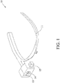
- an interactive display device 10 of a first embodiment includes a body 11, an optical project unit 13, an image capture unit 14, and a display unit 15.
- the body 11 may be an eyeglass, a mobile phone or a tablet computer. In an embodiment, the body 11 will be described as an eyeglass, but the present disclosure is not limited thereto.
- the optical project unit 13 is provided on the body 11, for example, on the right stand of a spectacle frame.
- the body 11 is provided with a microprocessor (not shown), and the optical project unit 13 is controlled by a microprocessor and can project a pattern to a scene.
- the image capture unit 14 is also provided on the body 11, for example, on the right stand of a spectacle frame.
- the image capture unit 14 is also controlled by the microprocessor. After the optical project unit 13 projects the pattern to the scene, the image capture unit 14 captures the image containing the pattern in the scene.
- the display unit 15 is also provided on the body 11, for example, in front of the position of the right lens of a spectacle. When a user wears the interactive display device 10, the right eye of the user can see the image displayed by the display unit 15.
- the arrangement positions of the optical project unit 13, the image capture unit 14, and the display unit 15 are merely examples, and the present disclosure is not limited thereto.
- the optical project unit 13 is a laser having a laser light source and a diffraction element, wherein the diffraction element may be an optical hologram or a microstructural optical film.
- the optical project unit 13 may project a pattern through a laser light source and a diffraction element, and the pattern is a checkerboard pattern or a concentric circle pattern.
- the pattern 44 is a checkerboard pattern, where the horizontal axis is marked by A to F and the vertical axis is marked by 1 to 4. Nevertheless, the present disclosure is not limited to the form of the pattern, nor the designations of the vertical and horizontal axes.
- the image capture unit 14 is a camera, which may comprise a color complementary metal-oxide-semiconductor (CMOS) image sensor or a color-coupled device (CCD) image sensor, but the disclosure is not limited thereto.
- CMOS complementary metal-oxide-semiconductor
- CCD color-coupled device
- the display unit 15 is a micro-display panel, such as a liquid-crystal display (LCD) or a panel produced by liquid crystal on silicon (LCOS) technology, with a virtual image magnifying optical element in the panel, which can magnify an image captured by the image capture unit 14 to a degree that users can view.
- LCD liquid-crystal display
- LCOS liquid crystal on silicon
- the interactive display device 10 of a second embodiment according to the present disclosure is different from the first embodiment in that the optical project unit 13 and the image capture unit 14 are not directly provided on the body 11.
- the interactive display device 10 further includes an angle adjustment unit 17 provided on the body 11, for example, on a right stand of a spectacle frame, and the optical project unit 13 and the image capture unit 14 are connected to the body 11 through the angle adjustment unit 17.
- the angle adjustment unit 17 is a spindle motor, such that the optical projection unit 13 and the image pickup unit 14 can simultaneously rotate with respect to the body 11.
- the rotation method may be that the microprocessor inside the body 11 controls the spindle motor according to a tilt angle detected by a gyroscope inside the body 11 to further control the rotation angle of the optical project unit 13 and the image capture unit 14.
- the angle adjustment unit 17 may be a rotary shaft without power, and a user may manually adjust the rotation angles of the optical project unit 13 and the image capture unit 14.
- the purpose of providing the angle adjustment unit 17 in the interactive display device 10 of the present disclosure is to align the line of sight of a user with the pattern projection direction of the optical project unit and the image capture direction of the image capture unit.
- FIG. 3A after a user wears the interactive display device 10 according to the present disclosure and plans to project a pattern 44 in a scene 45, if the interactive display device 10 is not provided with the angle adjustment unit 17, the sight line 41 of the user is liable to be inconsistent with the pattern projection direction 42 of the optical project unit 13 and the image capture direction 43 of the image capture unit 14 when the user bows the head to look at the near scene 45. This is due to the viewing angle of the human eye is considerably large.
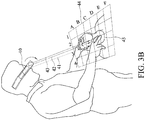
- the interactive display device 10 To accurately project the pattern 44 onto the scene 45, the user obviously has to take a lower head posture, which is likely to cause neck discomfort. Therefore, as shown in FIG. 3B , the interactive display device 10 according to the present disclosure is provided with an angle adjustment unit 17 that projects the pattern 44 to the scene 45 by rotating the optical project unit 13 and the image capture unit 14. The user does not have to take a lower head position, and hence the interactive display device 10 does not incur a burden on the user.
- the interactive display device 10 of the third example according to the present disclosure is different from the first embodiment in that the interactive display device 10 of the third embodiment further comprises a reflection unit 18.
- the reflection unit 18 is provided on the body 11 through a spindle motor 19, for example, on a right stand of a spectacle frame.
- the optical project unit 13 and the image capture unit 14 are provided on the right stand of the spectacle frame, but below the reflection unit 18. That is, the reflection unit 18 is provided in the proceeding path of the pattern projection direction of the optical project unit 13 and the image capture direction of the image capture unit 14.
- the reflective unit 18 may be a reflecting mirror, and may be used to change the pattern projection direction and the image capture direction.
- the method is that a microprocessor within the body 11 controls the spindle motor 19 according to a tilt angle detected by a gyroscope provided within the body 11 to further control the rotation angle of the reflection unit 18.
- the interactive display device 10 may further comprise a wireless transmission unit (not shown) for transmitting images to a terminal unit to display.
- the wireless transmission unit may be configured to use Bluetooth, Wi-Fi, 3G or 4G wireless network transmission, but the disclosure is not limited thereto.
- the interactive display system 1 comprises an interactive display device 10 and an electronic device 20.
- the interactive display device 10 comprises a body 11, an optical project unit 13, an image capture unit 14, and a display unit 15.
- the body 11 of the interactive display device 10 is provided with a microprocessor 12 for controlling the optical project unit 13 and the image capture unit 14.
- the detailed technical content of the interactive display device 10 has been described above and will not be described in detail here.
- the electronic device 20 is connected to a wireless transmission unit 16 of the interactive display device 10 via a network 30 for receiving an image containing a pattern captured by the image capture unit 14 of the interactive display device 10.
- the electronic device 20 comprises a screen 22 on which images containing the patterns captured by the image capture unit 14 of the interactive display device 10 are displayed.
- the electronic device 20 is a mobile phone, tablet or desktop computer with a processor, and the network may be a Bluetooth, Wi-Fi, 3G or 4G wireless network.
- the electronic device 20 comprises a marking module 21.
- the module according to the present disclosure is a software that can be executed by a processor.
- the marking module 21 is used to mark an image, for example, editing the image by using an image software such as MS Paint.
- the tagged image can be transmitted via the network 30 to the interactive display device 10 and displayed on the display unit 15.
- a user wears the interactive display device 10 and projects a pattern 44 on a scene 45 (for example, a casualty), and the user can see the image containing the pattern 44 in the display unit 15.
- the interactive display device 10 transfers the captured image containing the pattern 44 to the electronic device 20 through the network 30 and displays the image on the screen 22 of the electronic device 20.
- the user viewing the electronic device 20 can easily communicate with the user wearing the interactive display device 10 based on the pattern 44 because the image contains the pattern 44 (for example, a checkerboard pattern), and both parties have common coordinate cognition. For example, the position of pressing C3 may be indicated.
- the user viewing the electronic device 20 may make a mark 47 to the image on the screen 22 (e.g., draw a circle at the C3 position), and the marked image may be transmitted to the interactive display device 10 through the network 30 and displayed on the display unit 15.
- the user wearing the interactive display device 10 can see the mark 47' in the image on the display unit 15.
- the precise position can be determined by the marks 47 and 47' in the images such that communications of both sides can go more smoothly.
- the body 11 of the interactive display device 10 according to the present disclosure may be a mobile phone or a tablet computer
- the optical project unit 13 may be a plug-in project unit
- the image capturing unit 14 may be a camera on a mobile phone or a tablet computer
- the display unit 15 may be a screen on a mobile phone or a tablet computer.
- the present disclosure is not limited thereto.
- An interactive display device 10 of a fourth embodiment according to the present disclosure comprises a body 11, an optical project unit 13, an image capture unit 14, and a display 15.
- the body 11 is a helmet.
- the present disclosure is described as the body 11 is exemplified by, but not limited to, a helmet.
- the display unit 15 is disposed on the body 11.
- the interactive display device 10 may have two display units 15 disposed at positions in front of two eyes of a user, to allow the user to view the image displayed on the display units 15 with two eyes, respectively.
- the optical project unit 13 and the image capture unit 14 may be connected to the body 11 via the angle adjustment unit 17.
- the angle adjustment unit 17 may have a bendable structure such as a plastic soft pipe having a wire embedded therein.
- the angle adjustment unit 17 allows the optical project unit 13 and the image capture unit 14 to be fixed to a specific position with respect to the body 11 at the same time. Therefore, a user is allowed to use the angle adjustment unit 17 to adjust the pattern projection direction of the optical project unit 13 and the image capture direction of the image capture unit 14.
- the optical project unit 13 is, but not limited to, a light emitting diode, or a laser having a laser light source and a diffraction element.
- the optical project unit 13 surrounds the image capture unit 14, and uses a knob 23 to adjust the intensity of light emitted by the optical project unit 13 such as a light emitting diode.
- FIG. 8 illustrates an interactive display device 10 of a fifth embodiment according to the present disclosure.
- the fifth embodiment differs from the fourth embodiment in the number of the angle adjustment unit 17, the optical project unit 13 and the image capture unit 14.
- the interactive display device 10 shown in FIG. 8 has two angle adjustment units 17, two optical project units 13 and two image capture units 14, and can constitute 3D images, to allow a user to view 3D images via the display unit 15.
- FIG. 9 illustrates an interactive display device 10 of a sixth embodiment according to the present disclosure.
- the sixth embodiment differs from the fourth embodiment of FIG. 7 in that the angle adjustment unit 17 of the sixth embodiment can be a clamshell-type structure pivotally connected to the body 11.
- FIG. 10 illustrates an interactive display device 10 of a seventh embodiment according to the present disclosure.
- the seventh embodiment differs from the fourth embodiment of FIG. 7 in that the angle adjustment unit 17 of the seventh embodiment can be universal bearing.
- the interactive display device 10 allows a user to view images by aiming the eyes directly on the display unit 15 when using the optical project unit 13 and the image capture unit 14 to capture images, without bowing the head to look downward. A user can easily and quickly manipulate the interactive display device 10 according to the present disclosure.
- the optical project unit of the interactive display device can project a pattern
- the image capture unit of the interactive display device can capture an image containing the pattern, which can be transmitted to an electronic device, such that both sides of users can precisely position through the images containing the pattern.
- users can also mark the images containing the pattern by a marking module of an electronic device. Therefore, the present disclosure has an effect of easy communication, and allows a user to manipulate with the eyes and hands at his will and ease.
- young doctors can wear the interactive display device of the present disclosure for examining patients, and senior doctors can assist in determining patients' conditions by images containing a pattern displayed by the electronic device or mark the images for facilitating the communication between the two sides.
- the present disclosure can further be applied in the fields of maintenance, disaster relief, medical treatment and surgery, including watch/clock maintenance, vehicle maintenance, oral treatment, intravenous injection, surgery, cooking teaching guidance, eyelash extension and nail painting, as a bridge between the first-line user and the back-end support center.
Landscapes
- Engineering & Computer Science (AREA)
- Physics & Mathematics (AREA)
- General Physics & Mathematics (AREA)
- Health & Medical Sciences (AREA)
- Theoretical Computer Science (AREA)
- Life Sciences & Earth Sciences (AREA)
- Surgery (AREA)
- Optics & Photonics (AREA)
- General Engineering & Computer Science (AREA)
- Nuclear Medicine, Radiotherapy & Molecular Imaging (AREA)
- Multimedia (AREA)
- Signal Processing (AREA)
- Animal Behavior & Ethology (AREA)
- General Health & Medical Sciences (AREA)
- Veterinary Medicine (AREA)
- Public Health (AREA)
- Molecular Biology (AREA)
- Medical Informatics (AREA)
- Heart & Thoracic Surgery (AREA)
- Biomedical Technology (AREA)
- Pathology (AREA)
- Oral & Maxillofacial Surgery (AREA)
- Gynecology & Obstetrics (AREA)
- Radiology & Medical Imaging (AREA)
- Human Computer Interaction (AREA)
- Computer Hardware Design (AREA)
- Software Systems (AREA)
- Computer Graphics (AREA)
- Computer Vision & Pattern Recognition (AREA)
- Robotics (AREA)
- Controls And Circuits For Display Device (AREA)
- User Interface Of Digital Computer (AREA)
Abstract
Description
- The present disclosure is based on, and claims priority from Taiwan Application Number
105138621, filed on November 24, 2016 - The present disclosure relates to display devices and display systems, and, especially, to an interactive display device and an interactive display system having image positioning capability.
- The emergence and popularization of head-mounted display (HMD) or smart glasses (such as Google glass) has been widely used in various fields, such as maintenance, disaster relief, medical treatment, surgery and other special fields. In these applications, the user can use the head-mounted display or smart glasses to obtain the immediate image, and transmit the image to remote ends to communicate with them. However, the user and the remote ends cannot accurately communicate with the image alone. For example, the precise location to be repaired or to be rescued cannot be described, but only a rough location indicated by up, down, left, and right directions with oral expressions. This not only results in longer communication time between the two sides, but also is more likely to cause time delay for repair or rescue.
- Therefore, how to provide an interactive display device and an interactive display system having image positioning capability is one of the urgent issues to be solved.
- An interactive display device is provided, comprising: a body having a microprocessor therein, an optical project unit provided on the body and controlled by the microprocessor for projecting a pattern to a scene; an image capture unit provided on the body and controlled by the microprocessor for capturing an image containing the pattern in the scene; and a display unit provided on the body for displaying the image.
- An interactive display system is also provided, comprising an interactive display device and an electronic device, wherein the interactive display device comprises a body having a microprocessor therein, an optical project unit provided on the body and controlled by the microprocessor for projecting a pattern to a scene, an image capture unit provided on the body and controlled by the microprocessor for capturing an image containing the pattern in the scene, and a display unit provided on the body for displaying the image, and the electronic device is connected to the interactive display device through a network for receiving and displaying the image on a screen of the electronic device.
-
-
FIG. 1 is a three-dimensional schematic diagram illustrating a first embodiment of an interactive display device according to the present disclosure; -
FIG. 2 is a three-dimensional schematic diagram illustrating a second embodiment of an interactive display device according to the present disclosure; -
FIGs. 3A and3B are schematic diagrams of an interactive display device according to the present disclosure; -
FIG. 4 is a three-dimensional schematic diagram illustrating a third embodiment of an interactive display device according to the present disclosure; -
FIG. 5 is a functional block diagram of an interactive display system according to the present disclosure; -
FIG. 6 is a schematic diagram of an interactive display system according to the present disclosure; -
FIG. 7 is a schematic diagram of an interactive display system of a fourth embodiment according to the present disclosure; -
FIG. 8 is a schematic diagram of an interactive display system of a fifth embodiment according to the present disclosure; -
FIG. 9 is a schematic diagram of an interactive display system of a sixth embodiment according to the present disclosure; and -
FIG. 10 is a schematic diagram of an interactive display system of a seventh embodiment according to the present disclosure. - The embodiments of the present disclosure are explained by following specific examples. One skilled in the art can readily comprehend other advantages and efficacies of the present disclosure in view of the disclosure of this specification. The present disclosure can also be implemented or applied by other specific examples.
- Referring to
FIG. 1 , aninteractive display device 10 of a first embodiment according to the present disclosure includes abody 11, anoptical project unit 13, animage capture unit 14, and adisplay unit 15. Thebody 11 may be an eyeglass, a mobile phone or a tablet computer. In an embodiment, thebody 11 will be described as an eyeglass, but the present disclosure is not limited thereto. - As shown in
FIG. 1 , theoptical project unit 13 is provided on thebody 11, for example, on the right stand of a spectacle frame. Thebody 11 is provided with a microprocessor (not shown), and theoptical project unit 13 is controlled by a microprocessor and can project a pattern to a scene. - The
image capture unit 14 is also provided on thebody 11, for example, on the right stand of a spectacle frame. Theimage capture unit 14 is also controlled by the microprocessor. After theoptical project unit 13 projects the pattern to the scene, theimage capture unit 14 captures the image containing the pattern in the scene. - The
display unit 15 is also provided on thebody 11, for example, in front of the position of the right lens of a spectacle. When a user wears theinteractive display device 10, the right eye of the user can see the image displayed by thedisplay unit 15. The arrangement positions of theoptical project unit 13, theimage capture unit 14, and thedisplay unit 15 are merely examples, and the present disclosure is not limited thereto. - In an embodiment, the
optical project unit 13 is a laser having a laser light source and a diffraction element, wherein the diffraction element may be an optical hologram or a microstructural optical film. Theoptical project unit 13 may project a pattern through a laser light source and a diffraction element, and the pattern is a checkerboard pattern or a concentric circle pattern. As shown inFIG. 3A , thepattern 44 is a checkerboard pattern, where the horizontal axis is marked by A to F and the vertical axis is marked by 1 to 4. Nevertheless, the present disclosure is not limited to the form of the pattern, nor the designations of the vertical and horizontal axes. - In an embodiment, the
image capture unit 14 is a camera, which may comprise a color complementary metal-oxide-semiconductor (CMOS) image sensor or a color-coupled device (CCD) image sensor, but the disclosure is not limited thereto. - In an embodiment, the
display unit 15 is a micro-display panel, such as a liquid-crystal display (LCD) or a panel produced by liquid crystal on silicon (LCOS) technology, with a virtual image magnifying optical element in the panel, which can magnify an image captured by theimage capture unit 14 to a degree that users can view. - Please refer to the
interactive display device 10 of a second embodiment according to the present disclosure illustrated byFIG. 2 . Only the difference between the second embodiment and the first embodiment will be described. Theinteractive display device 10 of the second embodiment according to the present disclosure is different from the first embodiment in that theoptical project unit 13 and theimage capture unit 14 are not directly provided on thebody 11. In an embodiment, theinteractive display device 10 further includes anangle adjustment unit 17 provided on thebody 11, for example, on a right stand of a spectacle frame, and theoptical project unit 13 and theimage capture unit 14 are connected to thebody 11 through theangle adjustment unit 17. - In an embodiment, the
angle adjustment unit 17 is a spindle motor, such that theoptical projection unit 13 and theimage pickup unit 14 can simultaneously rotate with respect to thebody 11. The rotation method may be that the microprocessor inside thebody 11 controls the spindle motor according to a tilt angle detected by a gyroscope inside thebody 11 to further control the rotation angle of theoptical project unit 13 and theimage capture unit 14. - In another embodiment, the
angle adjustment unit 17 may be a rotary shaft without power, and a user may manually adjust the rotation angles of theoptical project unit 13 and theimage capture unit 14. - The purpose of providing the
angle adjustment unit 17 in theinteractive display device 10 of the present disclosure is to align the line of sight of a user with the pattern projection direction of the optical project unit and the image capture direction of the image capture unit. Referring toFIG. 3A , after a user wears theinteractive display device 10 according to the present disclosure and plans to project apattern 44 in ascene 45, if theinteractive display device 10 is not provided with theangle adjustment unit 17, thesight line 41 of the user is liable to be inconsistent with thepattern projection direction 42 of theoptical project unit 13 and theimage capture direction 43 of theimage capture unit 14 when the user bows the head to look at thenear scene 45. This is due to the viewing angle of the human eye is considerably large. To accurately project thepattern 44 onto thescene 45, the user obviously has to take a lower head posture, which is likely to cause neck discomfort. Therefore, as shown inFIG. 3B , theinteractive display device 10 according to the present disclosure is provided with anangle adjustment unit 17 that projects thepattern 44 to thescene 45 by rotating theoptical project unit 13 and theimage capture unit 14. The user does not have to take a lower head position, and hence theinteractive display device 10 does not incur a burden on the user. - Please refer to the
interactive display device 10 of a third example according to the present disclosure illustrated inFIG. 4 . Only the difference between the third embodiment and the first embodiment will be described. Theinteractive display device 10 of the third example according to the present disclosure is different from the first embodiment in that theinteractive display device 10 of the third embodiment further comprises areflection unit 18. Thereflection unit 18 is provided on thebody 11 through aspindle motor 19, for example, on a right stand of a spectacle frame. In an embodiment, theoptical project unit 13 and theimage capture unit 14 are provided on the right stand of the spectacle frame, but below thereflection unit 18. That is, thereflection unit 18 is provided in the proceeding path of the pattern projection direction of theoptical project unit 13 and the image capture direction of theimage capture unit 14. In an embodiment, thereflective unit 18 may be a reflecting mirror, and may be used to change the pattern projection direction and the image capture direction. The method is that a microprocessor within thebody 11 controls thespindle motor 19 according to a tilt angle detected by a gyroscope provided within thebody 11 to further control the rotation angle of thereflection unit 18. - In an embodiment, the
interactive display device 10 may further comprise a wireless transmission unit (not shown) for transmitting images to a terminal unit to display. In an embodiment, the wireless transmission unit may be configured to use Bluetooth, Wi-Fi, 3G or 4G wireless network transmission, but the disclosure is not limited thereto. - Referring to
FIGs. 1 and5 , the interactive display system 1 according to the present disclosure comprises aninteractive display device 10 and anelectronic device 20. Theinteractive display device 10 comprises abody 11, anoptical project unit 13, animage capture unit 14, and adisplay unit 15. Thebody 11 of theinteractive display device 10 is provided with amicroprocessor 12 for controlling theoptical project unit 13 and theimage capture unit 14. The detailed technical content of theinteractive display device 10 has been described above and will not be described in detail here. - The
electronic device 20 is connected to awireless transmission unit 16 of theinteractive display device 10 via anetwork 30 for receiving an image containing a pattern captured by theimage capture unit 14 of theinteractive display device 10. Theelectronic device 20 comprises ascreen 22 on which images containing the patterns captured by theimage capture unit 14 of theinteractive display device 10 are displayed. - In an embodiment, the
electronic device 20 is a mobile phone, tablet or desktop computer with a processor, and the network may be a Bluetooth, Wi-Fi, 3G or 4G wireless network. - In an embodiment, the
electronic device 20 comprises a markingmodule 21. The module according to the present disclosure is a software that can be executed by a processor. The markingmodule 21 is used to mark an image, for example, editing the image by using an image software such as MS Paint. The tagged image can be transmitted via thenetwork 30 to theinteractive display device 10 and displayed on thedisplay unit 15. - As shown in
FIG. 6 , when the interactive display system 1 according to the present disclosure is applied, a user wears theinteractive display device 10 and projects apattern 44 on a scene 45 (for example, a casualty), and the user can see the image containing thepattern 44 in thedisplay unit 15. Theinteractive display device 10 transfers the captured image containing thepattern 44 to theelectronic device 20 through thenetwork 30 and displays the image on thescreen 22 of theelectronic device 20. The user viewing theelectronic device 20 can easily communicate with the user wearing theinteractive display device 10 based on thepattern 44 because the image contains the pattern 44 (for example, a checkerboard pattern), and both parties have common coordinate cognition. For example, the position of pressing C3 may be indicated. In an embodiment, the user viewing theelectronic device 20 may make amark 47 to the image on the screen 22 (e.g., draw a circle at the C3 position), and the marked image may be transmitted to theinteractive display device 10 through thenetwork 30 and displayed on thedisplay unit 15. The user wearing theinteractive display device 10 can see the mark 47' in the image on thedisplay unit 15. The precise position can be determined by themarks 47 and 47' in the images such that communications of both sides can go more smoothly. - Although the
interactive display device 10 according to the present disclosure is explained by taking an example of thebody 11 as a spectacle, thebody 11 of theinteractive display device 10 according to the present disclosure may be a mobile phone or a tablet computer, theoptical project unit 13 may be a plug-in project unit, theimage capturing unit 14 may be a camera on a mobile phone or a tablet computer, and thedisplay unit 15 may be a screen on a mobile phone or a tablet computer. The present disclosure is not limited thereto. - Please refer to
FIG. 7 . Aninteractive display device 10 of a fourth embodiment according to the present disclosure comprises abody 11, anoptical project unit 13, animage capture unit 14, and adisplay 15. In an embodiment, thebody 11 is a helmet. In the following, the present disclosure is described as thebody 11 is exemplified by, but not limited to, a helmet. - The
display unit 15 is disposed on thebody 11. In an embodiment, theinteractive display device 10 may have twodisplay units 15 disposed at positions in front of two eyes of a user, to allow the user to view the image displayed on thedisplay units 15 with two eyes, respectively. - The
optical project unit 13 and theimage capture unit 14 may be connected to thebody 11 via theangle adjustment unit 17. In an embodiment, theangle adjustment unit 17 may have a bendable structure such as a plastic soft pipe having a wire embedded therein. Theangle adjustment unit 17 allows theoptical project unit 13 and theimage capture unit 14 to be fixed to a specific position with respect to thebody 11 at the same time. Therefore, a user is allowed to use theangle adjustment unit 17 to adjust the pattern projection direction of theoptical project unit 13 and the image capture direction of theimage capture unit 14. - In an embodiment, the
optical project unit 13 is, but not limited to, a light emitting diode, or a laser having a laser light source and a diffraction element. In another embodiment, theoptical project unit 13 surrounds theimage capture unit 14, and uses aknob 23 to adjust the intensity of light emitted by theoptical project unit 13 such as a light emitting diode. - Please refer to
FIG. 8 , which illustrates aninteractive display device 10 of a fifth embodiment according to the present disclosure. The fifth embodiment differs from the fourth embodiment in the number of theangle adjustment unit 17, theoptical project unit 13 and theimage capture unit 14. Theinteractive display device 10 shown inFIG. 8 has twoangle adjustment units 17, twooptical project units 13 and twoimage capture units 14, and can constitute 3D images, to allow a user to view 3D images via thedisplay unit 15. - Please refer to
FIG. 9 , which illustrates aninteractive display device 10 of a sixth embodiment according to the present disclosure. The sixth embodiment differs from the fourth embodiment ofFIG. 7 in that theangle adjustment unit 17 of the sixth embodiment can be a clamshell-type structure pivotally connected to thebody 11. - Please refer to
FIG. 10 , which illustrates aninteractive display device 10 of a seventh embodiment according to the present disclosure. The seventh embodiment differs from the fourth embodiment ofFIG. 7 in that theangle adjustment unit 17 of the seventh embodiment can be universal bearing. - The
interactive display device 10 according to the present disclosure allows a user to view images by aiming the eyes directly on thedisplay unit 15 when using theoptical project unit 13 and theimage capture unit 14 to capture images, without bowing the head to look downward. A user can easily and quickly manipulate theinteractive display device 10 according to the present disclosure. - With the interactive display device and system according to the present disclosure, the optical project unit of the interactive display device can project a pattern, and the image capture unit of the interactive display device can capture an image containing the pattern, which can be transmitted to an electronic device, such that both sides of users can precisely position through the images containing the pattern. Moreover, users can also mark the images containing the pattern by a marking module of an electronic device. Therefore, the present disclosure has an effect of easy communication, and allows a user to manipulate with the eyes and hands at his will and ease. In the application, young doctors can wear the interactive display device of the present disclosure for examining patients, and senior doctors can assist in determining patients' conditions by images containing a pattern displayed by the electronic device or mark the images for facilitating the communication between the two sides. The present disclosure can further be applied in the fields of maintenance, disaster relief, medical treatment and surgery, including watch/clock maintenance, vehicle maintenance, oral treatment, intravenous injection, surgery, cooking teaching guidance, eyelash extension and nail painting, as a bridge between the first-line user and the back-end support center.
- The embodiments described above are only illustrative of the technical principles, features, and effects of the present disclosure, and are not intended to limit the scope of the present disclosure. Any person skilled in the art can, without departing from the spirit and scope of the present disclosure, modify and change the embodiments. However, any equivalent modifications and variations that can be made with the teachings of the present disclosure are intended to be encompassed by the following claims. And the scope of protection of the present disclosure is set forth in the following claims.
Claims (27)
- An interactive display device, comprising:a body having a microprocessor therein;an optical project unit provided on the body and controlled by the microprocessor for projecting a pattern to a scene;an image capture unit provided on the body and controlled by the microprocessor for capturing an image containing the pattern in the scene; anda display unit provided on the body for displaying the image.
- The interactive display device according to claim 1, wherein the body is an eyeglass, a helmet, a mobile phone or a tablet computer.
- The interactive display device according to claim 1, wherein the optical project unit is a light emitting diode, or a laser having a laser light source and a diffraction element.
- The interactive display device according to claim 3, wherein the diffraction element is an optical whole-picture or a microstructural optical film.
- The interactive display device according to claim 1, wherein the pattern is a checkerboard pattern or a concentric circle pattern.
- The interactive display device according to claim 1, wherein the image capture unit is a camera including a color complementary metal semiconductor image sensor or a color photosensitive coupling element image sensor.
- The interactive display device according to claim 1, wherein the display unit is a micro-display panel having a virtual image magnifying optical element.
- The interactive display device according to claim 1, further comprising a wireless transmission unit configured for transmitting the image to a terminal unit to display, wherein the wireless transmission unit uses Bluetooth, Wi-Fi, 3G or 4G wireless network transmission.
- The interactive display device according to claim 1, further comprising an angle adjustment unit provided on the body and connected to the optical project unit and the image capture unit such that the optical project unit and the image capture unit rotate simultaneously with respect to the body, or are fixed to a specific position.
- The interactive display device according to claim 9, wherein the angle adjustment unit has a bendable structure, a clamshell-type structure or a universal bearing.
- The interactive display device according to claim 9, wherein the angle adjustment unit is a spindle motor, and the microprocessor controls the spindle motor in accordance with a gyroscope provided in the body to control a rotation angle of the optical project unit and the image capture unit.
- The interactive display device according to claim 1, further comprising a reflecting unit provided on the body and located in a pattern projection direction of the optical project unit and an image capture direction of the image capture unit for changing the pattern projection direction and the image capture direction.
- The interactive display device according to claim 12, wherein the reflecting unit is provided on the body through a spindle motor, and the microprocessor controls the spindle motor in accordance with a gyroscope provided in the body to control a rotation angle of the reflection unit.
- An interactive display system comprising:an interactive display device comprising:a body having a microprocessor therein;an optical project unit provided on the body and controlled by the microprocessor for projecting a pattern to a scene;an image capture unit provided on the body and controlled by the microprocessor for capturing an image containing the pattern in the scene; anda display unit provided on the body for displaying the image; andan electronic device connected to the interactive display device through a network to receive and display the image on a screen of the electronic device.
- The interactive display system according to claim 14, wherein the body is an eyeglass, a helmet, a mobile phone or a tablet computer, and the electronic device is a mobile phone, a tablet computer or a desktop computer.
- The interactive display system according to claim 14, wherein the optical project unit is a light emitting diode, or a laser having a laser light source and a diffraction element.
- The interactive display system according to claim 16, wherein the diffraction element is an optical whole-picture or a microstructural optical film.
- The interactive display system according to claim 14, wherein the pattern is a checkerboard pattern or a concentric circle pattern.
- The interactive display system according to claim 14, wherein the image capture unit is a camera including a color complementary metal semiconductor image sensor or a color photosensitive coupling element image sensor.
- The interactive display system according to claim 14, wherein the display unit is a micro-display panel having a virtual image magnifying optical element.
- The interactive display system according to claim 14, wherein the interactive display device further includes a wireless transmission unit for being connected with the electronic device through the network, and the network is a Bluetooth, a Wi-Fi, 3G or 4G wireless network.
- The interactive display system according to claim 14, wherein the interactive display device further comprises an angle adjustment unit provided on the body and connected to the optical project unit and the image capture unit such that the optical project unit and the image capture unit rotate simultaneously with respect to the body, or are fixed to a specific position.
- The interactive display system according to claim 22, wherein the angle adjustment unit has a bendable structure, a clamshell-type structure or a universal bearing.
- The interactive display system according to claim 22, wherein the angle adjustment unit is a spindle motor, and the microprocessor controls the spindle motor in accordance with a gyroscope provided in the body to control a rotation angle of the optical project unit and the image capture unit.
- The interactive display system according to claim 14, wherein the interactive display device further comprises a reflecting unit provided on the body and located in a pattern projection direction of the optical project unit and an image capture direction of the image capture unit for changing the pattern projection direction and the image capture direction.
- The interactive display system according to claim 25, wherein the reflecting unit is provided on the body through a spindle motor, and the microprocessor controls the spindle motor in accordance with a gyroscope provided in the body to control a rotation angle of the reflection unit.
- The interactive display system according to claim 14, wherein the electronic device comprises a marking module for marking the image and the marked image can be transmitted to the interactive display device through the network and displayed on the display unit.
Applications Claiming Priority (1)
| Application Number | Priority Date | Filing Date | Title |
|---|---|---|---|
| TW105138621A TWI587206B (en) | 2016-11-24 | 2016-11-24 | Interactive display device and system thereof |
Publications (2)
| Publication Number | Publication Date |
|---|---|
| EP3327546A1 true EP3327546A1 (en) | 2018-05-30 |
| EP3327546B1 EP3327546B1 (en) | 2019-11-06 |
Family
ID=59030743
Family Applications (1)
| Application Number | Title | Priority Date | Filing Date |
|---|---|---|---|
| EP17171212.8A Active EP3327546B1 (en) | 2016-11-24 | 2017-05-16 | Interactive display device and interactive display system |
Country Status (4)
| Country | Link |
|---|---|
| US (1) | US20180144551A1 (en) |
| EP (1) | EP3327546B1 (en) |
| CN (1) | CN108107573B (en) |
| TW (1) | TWI587206B (en) |
Citations (4)
| Publication number | Priority date | Publication date | Assignee | Title |
|---|---|---|---|---|
| US20090096783A1 (en) * | 2005-10-11 | 2009-04-16 | Alexander Shpunt | Three-dimensional sensing using speckle patterns |
| US20120249416A1 (en) * | 2011-03-29 | 2012-10-04 | Giuliano Maciocci | Modular mobile connected pico projectors for a local multi-user collaboration |
| US20150302648A1 (en) * | 2014-02-18 | 2015-10-22 | Sulon Technologies Inc. | Systems and methods for mapping an environment using structured light |
| US20160140766A1 (en) * | 2012-12-12 | 2016-05-19 | Sulon Technologies Inc. | Surface projection system and method for augmented reality |
Family Cites Families (9)
| Publication number | Priority date | Publication date | Assignee | Title |
|---|---|---|---|---|
| US6678395B2 (en) * | 2001-03-22 | 2004-01-13 | Robert N. Yonover | Video search and rescue device |
| JP4504728B2 (en) * | 2003-11-21 | 2010-07-14 | 健爾 西 | Image display device and simulation device |
| EP2625845B1 (en) * | 2010-10-04 | 2021-03-03 | Gerard Dirk Smits | System and method for 3-d projection and enhancements for interactivity |
| TWI436150B (en) * | 2011-02-15 | 2014-05-01 | Asia Optical Co Inc | Projector with dual projection function and its external kit |
| US9069164B2 (en) * | 2011-07-12 | 2015-06-30 | Google Inc. | Methods and systems for a virtual input device |
| CN103135233B (en) * | 2011-12-01 | 2015-10-14 | 财团法人车辆研究测试中心 | Head-up display device |
| JP5912059B2 (en) * | 2012-04-06 | 2016-04-27 | ソニー株式会社 | Information processing apparatus, information processing method, and information processing system |
| CN203084407U (en) * | 2013-02-05 | 2013-07-24 | 陕西恒通智能机器有限公司 | Ultraviolet light projector |
| US20150097719A1 (en) * | 2013-10-03 | 2015-04-09 | Sulon Technologies Inc. | System and method for active reference positioning in an augmented reality environment |
-
2016
- 2016-11-24 TW TW105138621A patent/TWI587206B/en active
- 2016-12-23 US US15/390,407 patent/US20180144551A1/en not_active Abandoned
-
2017
- 2017-04-14 CN CN201710244207.7A patent/CN108107573B/en active Active
- 2017-05-16 EP EP17171212.8A patent/EP3327546B1/en active Active
Patent Citations (4)
| Publication number | Priority date | Publication date | Assignee | Title |
|---|---|---|---|---|
| US20090096783A1 (en) * | 2005-10-11 | 2009-04-16 | Alexander Shpunt | Three-dimensional sensing using speckle patterns |
| US20120249416A1 (en) * | 2011-03-29 | 2012-10-04 | Giuliano Maciocci | Modular mobile connected pico projectors for a local multi-user collaboration |
| US20160140766A1 (en) * | 2012-12-12 | 2016-05-19 | Sulon Technologies Inc. | Surface projection system and method for augmented reality |
| US20150302648A1 (en) * | 2014-02-18 | 2015-10-22 | Sulon Technologies Inc. | Systems and methods for mapping an environment using structured light |
Also Published As
| Publication number | Publication date |
|---|---|
| CN108107573A (en) | 2018-06-01 |
| CN108107573B (en) | 2020-09-29 |
| TWI587206B (en) | 2017-06-11 |
| EP3327546B1 (en) | 2019-11-06 |
| US20180144551A1 (en) | 2018-05-24 |
| TW201820108A (en) | 2018-06-01 |
Similar Documents
| Publication | Publication Date | Title |
|---|---|---|
| US12069233B2 (en) | Head-mounted augmented reality near eye display device | |
| US10725535B2 (en) | Head-worn image display apparatus for stereoscopic microsurgery | |
| US9298012B2 (en) | Eyebox adjustment for interpupillary distance | |
| US9223138B2 (en) | Pixel opacity for augmented reality | |
| CN204595327U (en) | Head-mounted display apparatus | |
| KR102812246B1 (en) | Smartphone-enabled portable augmented reality (AR) device and clip-on unit for adjustable attachment to user's glasses | |
| US20180180893A1 (en) | Auxiliary device for head-mounted displays | |
| TW201530187A (en) | Head mounted display and control method thereof | |
| CN108427193A (en) | Augmented reality display system | |
| CN204595328U (en) | Head-mounted display apparatus | |
| US20200133395A1 (en) | Display device and method for controlling display device | |
| CN108446011A (en) | A kind of medical householder method and equipment based on augmented reality | |
| CN117222932A (en) | Eye wearable device projector brightness control | |
| CN108427194A (en) | A kind of display methods and equipment based on augmented reality | |
| WO2016101861A1 (en) | Head-worn display device | |
| CN107111143B (en) | Vision system and film viewer | |
| EP3327546B1 (en) | Interactive display device and interactive display system | |
| TW201805689A (en) | External near-eye display device | |
| CN205899165U (en) | Three -dimensional piece ware of seeing of visual system and wear -type | |
| US20260050163A1 (en) | Devices with Adjustable Displays | |
| WO2023095082A1 (en) | Optical arrangement to create extended reality | |
| CN205142370U (en) | Hiccough |
Legal Events
| Date | Code | Title | Description |
|---|---|---|---|
| PUAI | Public reference made under article 153(3) epc to a published international application that has entered the european phase |
Free format text: ORIGINAL CODE: 0009012 |
|
| STAA | Information on the status of an ep patent application or granted ep patent |
Free format text: STATUS: REQUEST FOR EXAMINATION WAS MADE |
|
| 17P | Request for examination filed |
Effective date: 20170523 |
|
| AK | Designated contracting states |
Kind code of ref document: A1 Designated state(s): AL AT BE BG CH CY CZ DE DK EE ES FI FR GB GR HR HU IE IS IT LI LT LU LV MC MK MT NL NO PL PT RO RS SE SI SK SM TR |
|
| AX | Request for extension of the european patent |
Extension state: BA ME |
|
| STAA | Information on the status of an ep patent application or granted ep patent |
Free format text: STATUS: EXAMINATION IS IN PROGRESS |
|
| 17Q | First examination report despatched |
Effective date: 20181031 |
|
| GRAP | Despatch of communication of intention to grant a patent |
Free format text: ORIGINAL CODE: EPIDOSNIGR1 |
|
| STAA | Information on the status of an ep patent application or granted ep patent |
Free format text: STATUS: GRANT OF PATENT IS INTENDED |
|
| INTG | Intention to grant announced |
Effective date: 20190603 |
|
| GRAS | Grant fee paid |
Free format text: ORIGINAL CODE: EPIDOSNIGR3 |
|
| GRAA | (expected) grant |
Free format text: ORIGINAL CODE: 0009210 |
|
| STAA | Information on the status of an ep patent application or granted ep patent |
Free format text: STATUS: THE PATENT HAS BEEN GRANTED |
|
| AK | Designated contracting states |
Kind code of ref document: B1 Designated state(s): AL AT BE BG CH CY CZ DE DK EE ES FI FR GB GR HR HU IE IS IT LI LT LU LV MC MK MT NL NO PL PT RO RS SE SI SK SM TR |
|
| REG | Reference to a national code |
Ref country code: GB Ref legal event code: FG4D |
|
| REG | Reference to a national code |
Ref country code: CH Ref legal event code: EP Ref country code: AT Ref legal event code: REF Ref document number: 1199658 Country of ref document: AT Kind code of ref document: T Effective date: 20191115 |
|
| REG | Reference to a national code |
Ref country code: IE Ref legal event code: FG4D |
|
| REG | Reference to a national code |
Ref country code: DE Ref legal event code: R096 Ref document number: 602017008346 Country of ref document: DE |
|
| REG | Reference to a national code |
Ref country code: NL Ref legal event code: MP Effective date: 20191106 |
|
| REG | Reference to a national code |
Ref country code: LT Ref legal event code: MG4D |
|
| PG25 | Lapsed in a contracting state [announced via postgrant information from national office to epo] |
Ref country code: FI Free format text: LAPSE BECAUSE OF FAILURE TO SUBMIT A TRANSLATION OF THE DESCRIPTION OR TO PAY THE FEE WITHIN THE PRESCRIBED TIME-LIMIT Effective date: 20191106 Ref country code: BG Free format text: LAPSE BECAUSE OF FAILURE TO SUBMIT A TRANSLATION OF THE DESCRIPTION OR TO PAY THE FEE WITHIN THE PRESCRIBED TIME-LIMIT Effective date: 20200206 Ref country code: NO Free format text: LAPSE BECAUSE OF FAILURE TO SUBMIT A TRANSLATION OF THE DESCRIPTION OR TO PAY THE FEE WITHIN THE PRESCRIBED TIME-LIMIT Effective date: 20200206 Ref country code: PT Free format text: LAPSE BECAUSE OF FAILURE TO SUBMIT A TRANSLATION OF THE DESCRIPTION OR TO PAY THE FEE WITHIN THE PRESCRIBED TIME-LIMIT Effective date: 20200306 Ref country code: SE Free format text: LAPSE BECAUSE OF FAILURE TO SUBMIT A TRANSLATION OF THE DESCRIPTION OR TO PAY THE FEE WITHIN THE PRESCRIBED TIME-LIMIT Effective date: 20191106 Ref country code: LV Free format text: LAPSE BECAUSE OF FAILURE TO SUBMIT A TRANSLATION OF THE DESCRIPTION OR TO PAY THE FEE WITHIN THE PRESCRIBED TIME-LIMIT Effective date: 20191106 Ref country code: PL Free format text: LAPSE BECAUSE OF FAILURE TO SUBMIT A TRANSLATION OF THE DESCRIPTION OR TO PAY THE FEE WITHIN THE PRESCRIBED TIME-LIMIT Effective date: 20191106 Ref country code: LT Free format text: LAPSE BECAUSE OF FAILURE TO SUBMIT A TRANSLATION OF THE DESCRIPTION OR TO PAY THE FEE WITHIN THE PRESCRIBED TIME-LIMIT Effective date: 20191106 Ref country code: NL Free format text: LAPSE BECAUSE OF FAILURE TO SUBMIT A TRANSLATION OF THE DESCRIPTION OR TO PAY THE FEE WITHIN THE PRESCRIBED TIME-LIMIT Effective date: 20191106 Ref country code: GR Free format text: LAPSE BECAUSE OF FAILURE TO SUBMIT A TRANSLATION OF THE DESCRIPTION OR TO PAY THE FEE WITHIN THE PRESCRIBED TIME-LIMIT Effective date: 20200207 |
|
| PG25 | Lapsed in a contracting state [announced via postgrant information from national office to epo] |
Ref country code: IS Free format text: LAPSE BECAUSE OF FAILURE TO SUBMIT A TRANSLATION OF THE DESCRIPTION OR TO PAY THE FEE WITHIN THE PRESCRIBED TIME-LIMIT Effective date: 20200306 Ref country code: HR Free format text: LAPSE BECAUSE OF FAILURE TO SUBMIT A TRANSLATION OF THE DESCRIPTION OR TO PAY THE FEE WITHIN THE PRESCRIBED TIME-LIMIT Effective date: 20191106 Ref country code: RS Free format text: LAPSE BECAUSE OF FAILURE TO SUBMIT A TRANSLATION OF THE DESCRIPTION OR TO PAY THE FEE WITHIN THE PRESCRIBED TIME-LIMIT Effective date: 20191106 |
|
| PG25 | Lapsed in a contracting state [announced via postgrant information from national office to epo] |
Ref country code: AL Free format text: LAPSE BECAUSE OF FAILURE TO SUBMIT A TRANSLATION OF THE DESCRIPTION OR TO PAY THE FEE WITHIN THE PRESCRIBED TIME-LIMIT Effective date: 20191106 |
|
| PG25 | Lapsed in a contracting state [announced via postgrant information from national office to epo] |
Ref country code: DK Free format text: LAPSE BECAUSE OF FAILURE TO SUBMIT A TRANSLATION OF THE DESCRIPTION OR TO PAY THE FEE WITHIN THE PRESCRIBED TIME-LIMIT Effective date: 20191106 Ref country code: EE Free format text: LAPSE BECAUSE OF FAILURE TO SUBMIT A TRANSLATION OF THE DESCRIPTION OR TO PAY THE FEE WITHIN THE PRESCRIBED TIME-LIMIT Effective date: 20191106 Ref country code: ES Free format text: LAPSE BECAUSE OF FAILURE TO SUBMIT A TRANSLATION OF THE DESCRIPTION OR TO PAY THE FEE WITHIN THE PRESCRIBED TIME-LIMIT Effective date: 20191106 Ref country code: CZ Free format text: LAPSE BECAUSE OF FAILURE TO SUBMIT A TRANSLATION OF THE DESCRIPTION OR TO PAY THE FEE WITHIN THE PRESCRIBED TIME-LIMIT Effective date: 20191106 Ref country code: RO Free format text: LAPSE BECAUSE OF FAILURE TO SUBMIT A TRANSLATION OF THE DESCRIPTION OR TO PAY THE FEE WITHIN THE PRESCRIBED TIME-LIMIT Effective date: 20191106 |
|
| REG | Reference to a national code |
Ref country code: DE Ref legal event code: R097 Ref document number: 602017008346 Country of ref document: DE |
|
| REG | Reference to a national code |
Ref country code: AT Ref legal event code: MK05 Ref document number: 1199658 Country of ref document: AT Kind code of ref document: T Effective date: 20191106 |
|
| PG25 | Lapsed in a contracting state [announced via postgrant information from national office to epo] |
Ref country code: SK Free format text: LAPSE BECAUSE OF FAILURE TO SUBMIT A TRANSLATION OF THE DESCRIPTION OR TO PAY THE FEE WITHIN THE PRESCRIBED TIME-LIMIT Effective date: 20191106 Ref country code: SM Free format text: LAPSE BECAUSE OF FAILURE TO SUBMIT A TRANSLATION OF THE DESCRIPTION OR TO PAY THE FEE WITHIN THE PRESCRIBED TIME-LIMIT Effective date: 20191106 |
|
| PLBE | No opposition filed within time limit |
Free format text: ORIGINAL CODE: 0009261 |
|
| STAA | Information on the status of an ep patent application or granted ep patent |
Free format text: STATUS: NO OPPOSITION FILED WITHIN TIME LIMIT |
|
| 26N | No opposition filed |
Effective date: 20200807 |
|
| PG25 | Lapsed in a contracting state [announced via postgrant information from national office to epo] |
Ref country code: AT Free format text: LAPSE BECAUSE OF FAILURE TO SUBMIT A TRANSLATION OF THE DESCRIPTION OR TO PAY THE FEE WITHIN THE PRESCRIBED TIME-LIMIT Effective date: 20191106 Ref country code: SI Free format text: LAPSE BECAUSE OF FAILURE TO SUBMIT A TRANSLATION OF THE DESCRIPTION OR TO PAY THE FEE WITHIN THE PRESCRIBED TIME-LIMIT Effective date: 20191106 |
|
| PG25 | Lapsed in a contracting state [announced via postgrant information from national office to epo] |
Ref country code: LI Free format text: LAPSE BECAUSE OF NON-PAYMENT OF DUE FEES Effective date: 20200531 Ref country code: IT Free format text: LAPSE BECAUSE OF FAILURE TO SUBMIT A TRANSLATION OF THE DESCRIPTION OR TO PAY THE FEE WITHIN THE PRESCRIBED TIME-LIMIT Effective date: 20191106 Ref country code: CH Free format text: LAPSE BECAUSE OF NON-PAYMENT OF DUE FEES Effective date: 20200531 Ref country code: MC Free format text: LAPSE BECAUSE OF FAILURE TO SUBMIT A TRANSLATION OF THE DESCRIPTION OR TO PAY THE FEE WITHIN THE PRESCRIBED TIME-LIMIT Effective date: 20191106 |
|
| REG | Reference to a national code |
Ref country code: BE Ref legal event code: MM Effective date: 20200531 |
|
| PG25 | Lapsed in a contracting state [announced via postgrant information from national office to epo] |
Ref country code: LU Free format text: LAPSE BECAUSE OF NON-PAYMENT OF DUE FEES Effective date: 20200516 |
|
| PG25 | Lapsed in a contracting state [announced via postgrant information from national office to epo] |
Ref country code: IE Free format text: LAPSE BECAUSE OF NON-PAYMENT OF DUE FEES Effective date: 20200516 Ref country code: FR Free format text: LAPSE BECAUSE OF NON-PAYMENT OF DUE FEES Effective date: 20200531 |
|
| PG25 | Lapsed in a contracting state [announced via postgrant information from national office to epo] |
Ref country code: BE Free format text: LAPSE BECAUSE OF NON-PAYMENT OF DUE FEES Effective date: 20200531 |
|
| GBPC | Gb: european patent ceased through non-payment of renewal fee |
Effective date: 20210516 |
|
| PG25 | Lapsed in a contracting state [announced via postgrant information from national office to epo] |
Ref country code: GB Free format text: LAPSE BECAUSE OF NON-PAYMENT OF DUE FEES Effective date: 20210516 |
|
| PG25 | Lapsed in a contracting state [announced via postgrant information from national office to epo] |
Ref country code: TR Free format text: LAPSE BECAUSE OF FAILURE TO SUBMIT A TRANSLATION OF THE DESCRIPTION OR TO PAY THE FEE WITHIN THE PRESCRIBED TIME-LIMIT Effective date: 20191106 Ref country code: MT Free format text: LAPSE BECAUSE OF FAILURE TO SUBMIT A TRANSLATION OF THE DESCRIPTION OR TO PAY THE FEE WITHIN THE PRESCRIBED TIME-LIMIT Effective date: 20191106 Ref country code: CY Free format text: LAPSE BECAUSE OF FAILURE TO SUBMIT A TRANSLATION OF THE DESCRIPTION OR TO PAY THE FEE WITHIN THE PRESCRIBED TIME-LIMIT Effective date: 20191106 |
|
| PG25 | Lapsed in a contracting state [announced via postgrant information from national office to epo] |
Ref country code: MK Free format text: LAPSE BECAUSE OF FAILURE TO SUBMIT A TRANSLATION OF THE DESCRIPTION OR TO PAY THE FEE WITHIN THE PRESCRIBED TIME-LIMIT Effective date: 20191106 |
|
| PGFP | Annual fee paid to national office [announced via postgrant information from national office to epo] |
Ref country code: DE Payment date: 20250529 Year of fee payment: 9 |