EP3327525A1 - Manufacturing process management system, manufacturing process management method, and manufacturing process management program - Google Patents
Manufacturing process management system, manufacturing process management method, and manufacturing process management program Download PDFInfo
- Publication number
- EP3327525A1 EP3327525A1 EP15899567.0A EP15899567A EP3327525A1 EP 3327525 A1 EP3327525 A1 EP 3327525A1 EP 15899567 A EP15899567 A EP 15899567A EP 3327525 A1 EP3327525 A1 EP 3327525A1
- Authority
- EP
- European Patent Office
- Prior art keywords
- manufacturing process
- graph
- corresponds
- line segment
- display
- Prior art date
- Legal status (The legal status is an assumption and is not a legal conclusion. Google has not performed a legal analysis and makes no representation as to the accuracy of the status listed.)
- Withdrawn
Links
Images





Classifications
-
- G—PHYSICS
- G06—COMPUTING OR CALCULATING; COUNTING
- G06Q—INFORMATION AND COMMUNICATION TECHNOLOGY [ICT] SPECIALLY ADAPTED FOR ADMINISTRATIVE, COMMERCIAL, FINANCIAL, MANAGERIAL OR SUPERVISORY PURPOSES; SYSTEMS OR METHODS SPECIALLY ADAPTED FOR ADMINISTRATIVE, COMMERCIAL, FINANCIAL, MANAGERIAL OR SUPERVISORY PURPOSES, NOT OTHERWISE PROVIDED FOR
- G06Q10/00—Administration; Management
- G06Q10/06—Resources, workflows, human or project management; Enterprise or organisation planning; Enterprise or organisation modelling
- G06Q10/063—Operations research, analysis or management
- G06Q10/0639—Performance analysis of employees; Performance analysis of enterprise or organisation operations
-
- G—PHYSICS
- G05—CONTROLLING; REGULATING
- G05B—CONTROL OR REGULATING SYSTEMS IN GENERAL; FUNCTIONAL ELEMENTS OF SUCH SYSTEMS; MONITORING OR TESTING ARRANGEMENTS FOR SUCH SYSTEMS OR ELEMENTS
- G05B19/00—Program-control systems
- G05B19/02—Program-control systems electric
- G05B19/418—Total factory control, i.e. centrally controlling a plurality of machines, e.g. direct or distributed numerical control [DNC], flexible manufacturing systems [FMS], integrated manufacturing systems [IMS] or computer integrated manufacturing [CIM]
-
- G—PHYSICS
- G06—COMPUTING OR CALCULATING; COUNTING
- G06Q—INFORMATION AND COMMUNICATION TECHNOLOGY [ICT] SPECIALLY ADAPTED FOR ADMINISTRATIVE, COMMERCIAL, FINANCIAL, MANAGERIAL OR SUPERVISORY PURPOSES; SYSTEMS OR METHODS SPECIALLY ADAPTED FOR ADMINISTRATIVE, COMMERCIAL, FINANCIAL, MANAGERIAL OR SUPERVISORY PURPOSES, NOT OTHERWISE PROVIDED FOR
- G06Q50/00—Information and communication technology [ICT] specially adapted for implementation of business processes of specific business sectors, e.g. utilities or tourism
- G06Q50/04—Manufacturing
-
- G—PHYSICS
- G06—COMPUTING OR CALCULATING; COUNTING
- G06T—IMAGE DATA PROCESSING OR GENERATION, IN GENERAL
- G06T11/00—Two-dimensional [2D] image generation
- G06T11/20—Drawing from basic elements
- G06T11/26—Drawing of charts or graphs
-
- H—ELECTRICITY
- H04—ELECTRIC COMMUNICATION TECHNIQUE
- H04N—PICTORIAL COMMUNICATION, e.g. TELEVISION
- H04N23/00—Cameras or camera modules comprising electronic image sensors; Control thereof
- H04N23/60—Control of cameras or camera modules
- H04N23/63—Control of cameras or camera modules by using electronic viewfinders
-
- H—ELECTRICITY
- H04—ELECTRIC COMMUNICATION TECHNIQUE
- H04N—PICTORIAL COMMUNICATION, e.g. TELEVISION
- H04N23/00—Cameras or camera modules comprising electronic image sensors; Control thereof
- H04N23/90—Arrangement of cameras or camera modules, e.g. multiple cameras in TV studios or sports stadiums
-
- G—PHYSICS
- G05—CONTROLLING; REGULATING
- G05B—CONTROL OR REGULATING SYSTEMS IN GENERAL; FUNCTIONAL ELEMENTS OF SUCH SYSTEMS; MONITORING OR TESTING ARRANGEMENTS FOR SUCH SYSTEMS OR ELEMENTS
- G05B2219/00—Program-control systems
- G05B2219/30—Nc systems
- G05B2219/31—From computer integrated manufacturing till monitoring
- G05B2219/31447—Process error event detection and continuous process image detection, storage
-
- G—PHYSICS
- G05—CONTROLLING; REGULATING
- G05B—CONTROL OR REGULATING SYSTEMS IN GENERAL; FUNCTIONAL ELEMENTS OF SUCH SYSTEMS; MONITORING OR TESTING ARRANGEMENTS FOR SUCH SYSTEMS OR ELEMENTS
- G05B2219/00—Program-control systems
- G05B2219/30—Nc systems
- G05B2219/31—From computer integrated manufacturing till monitoring
- G05B2219/31472—Graphical display of process
-
- G—PHYSICS
- G05—CONTROLLING; REGULATING
- G05B—CONTROL OR REGULATING SYSTEMS IN GENERAL; FUNCTIONAL ELEMENTS OF SUCH SYSTEMS; MONITORING OR TESTING ARRANGEMENTS FOR SUCH SYSTEMS OR ELEMENTS
- G05B2219/00—Program-control systems
- G05B2219/30—Nc systems
- G05B2219/31—From computer integrated manufacturing till monitoring
- G05B2219/31479—Operator select part of process he wants to see, video image is displayed
-
- Y—GENERAL TAGGING OF NEW TECHNOLOGICAL DEVELOPMENTS; GENERAL TAGGING OF CROSS-SECTIONAL TECHNOLOGIES SPANNING OVER SEVERAL SECTIONS OF THE IPC; TECHNICAL SUBJECTS COVERED BY FORMER USPC CROSS-REFERENCE ART COLLECTIONS [XRACs] AND DIGESTS
- Y02—TECHNOLOGIES OR APPLICATIONS FOR MITIGATION OR ADAPTATION AGAINST CLIMATE CHANGE
- Y02P—CLIMATE CHANGE MITIGATION TECHNOLOGIES IN THE PRODUCTION OR PROCESSING OF GOODS
- Y02P90/00—Enabling technologies with a potential contribution to greenhouse gas [GHG] emissions mitigation
- Y02P90/02—Total factory control, e.g. smart factories, flexible manufacturing systems [FMS] or integrated manufacturing systems [IMS]
Definitions
- the present invention relates to a manufacturing process management system, a manufacturing process management method, and a manufacturing process management program.
- the user may desire to check how work in the process is performed.
- One aspect of the present invention provides a manufacturing process management system, a manufacturing process management method, and a manufacturing process management program that may display an image which corresponds to a designated process.
- the manufacturing process management system includes at least a management apparatus.
- the management apparatus has a graph display unit, a specifying unit, and an image display unit.
- a graph display unit displays a graph that represents an elapsed time from a start to a finish of each manufacturing process of the plurality of manufacturing processes, based on information of starting times and finishing times of the manufacturing processes, in a state where the plurality of manufacturing processes are divided into each of manufacturing processes in an execution order, while time axes are aligned in a same direction.
- a specifying unit specifies a captured image that corresponds to the manufacturing process which corresponds to a designated position among captured images of the plurality of manufacturing processes which are stored in a storage unit in accordance with the designated position on the displayed graph.
- the image display unit displays the specified captured image.
- An image that corresponds to a designated process may be displayed.
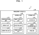
- FIG. 1 is a block diagram that illustrates one example of a configuration of the manufacturing process management system of the embodiment.
- a manufacturing process management system 1 illustrated in FIG. 1 has a management apparatus 100.
- the manufacturing process management system 1 may include a control apparatus of each manufacturing process, a control apparatus of a machine tool, and various kinds of examination apparatuses for a temperature examination and so forth, for example, other than the management apparatus 100.
- the management apparatus 100 may acquire log data from various kinds of apparatuses.
- the manufacturing process management system 1 may include a terminal apparatus for an administrator.
- the management apparatus 100 and various kinds of apparatuses are connected so as to be capable of mutual communication via a network, which is not illustrated. Note that in the following description, a case where various kinds of information of an assembly line of a product are acquired as log data.
- the management apparatus 100 of the manufacturing process management system 1 illustrated in FIG. 1 displays a manufacturing status of a product that is manufactured through a plurality of manufacturing processes.
- the displayed manufacturing statuses are a graph based on information of starting times and finishing times of the manufacturing processes based on the log data and captured images in which the manufacturing processes are captured, for example. Note that in the following description, the manufacturing process may simply be referred to as process.
- the management apparatus 100 displays a graph that represents the elapsed time from the start to the finish of each manufacturing process of a plurality of manufacturing processes, based on the information of the starting times and the finishing times of the manufacturing processes, in a state where the plurality of manufacturing processes are divided into each of manufacturing processes in the execution order, while the time axes are aligned in the same direction.
- the management apparatus 100 specifies the captured image that corresponds to the manufacturing process which corresponds to a designated position among captured images of the plurality of manufacturing processes that are stored in a storage unit in accordance with the designated position on the displayed graph.
- the management apparatus 100 displays the specified captured image. Accordingly, the management apparatus 100 may display the image that corresponds to the designated process.
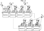
- FIG. 2 is a diagram that illustrates one example of the manufacturing processes.
- the manufacturing processes have seven processes of process A to process G.
- a worker carries out assembly work for the product.
- the starting and finishing timings of the respective processes are denoted by P1 to P8.
- P1 to P8 the starting and finishing timings of the respective processes.
- the starting and finishing timings of the processes may be different timings. Further, in the example of the manufacturing processes in FIG.
- a camera C1 that captures an image of process A a camera C2 that captures an image of process B and process C, a camera C3 that captures an image of process D, and a camera C4 that captures an image of processes E to G are placed.
- FIG. 3 is a diagram that illustrates one example of the graph which represents the statuses of the manufacturing processes.
- the graph that represents the statuses of the manufacturing processes corresponds to the manufacturing processes illustrated in FIG. 2 and is the graph that indicates the elapsed times in the respective processes.
- a time axis P1 of the time line graph illustrated in FIG. 3 corresponds to the starting timing P1 of process A in FIG. 2 .
- a time axis P2 of the time line graph illustrated in FIG. 3 corresponds to the finish timing of process A and the starting timing P2 of process B in FIG. 2 .
- time axes P3 to P8 of the time line graph illustrated in FIG. 3 correspond to the starting and finishing timings P3 to P8 of the respective processes in FIG. 2 .
- the upper portion of the time line graph in FIG. 3 indicates the relationships between the cameras C1 to C4 and processes A to G, which are illustrated in FIG. 2 .
- the flow of the product is indicated by line segments that connect the processes. The line segment is expressed as trace graph because the line segment traces the flow of the product in the manufacturing processes.
- the management apparatus 100 has a communication unit 110, a display unit 111, an operation unit 112, a storage unit 120, and a control unit 130.
- the management apparatus 100 may have various kinds of function units, which a known computer has, other than the function units illustrated in FIG. 1 , for example, function units such as various kinds of input devices and sound output devices.
- the communication unit 110 is realized by a network interface card (NIC), for example.
- the communication unit 110 is a communication interface that is connected with various kinds of apparatuses via a network, which is not illustrated, in a wired or wireless manner and that conducts communication of information among the various kinds of apparatuses.
- the communication unit 110 receives the log data from the various kinds of apparatuses.
- the communication unit 110 outputs the received log data to the control unit 130.
- the display unit 111 is a display device for displaying various kinds of information.
- the display unit 111 is realized as a display device by a liquid crystal display or the like, for example.
- the display unit 111 displays various kinds of screens such as display screens that are input from the control unit 130.
- the operation unit 112 is an input device that accepts various kinds of operations from the administrator of the manufacturing process management system 1.
- the operation unit 112 is realized as an input device by a keyboard, a mouse, or the like, for example.
- the operation unit 112 outputs an operation input by the administrator as operation information to the control unit 130.
- the operation information includes position information on the display screen in a pointing operation to bring a mouse cursor to a displayed object (hereinafter also referred to as cursor position information), for example.
- cursor position information position information on the display screen in a pointing operation to bring a mouse cursor to a displayed object
- the operation unit 112 may be realized as the input device by a touch panel or the like, and the display device of the display unit 111 and the input device of the operation unit 112 may be integrated.
- the storage unit 120 is realized by a storage apparatus such as a random access memory (RAM), a semiconductor memory element such as a flash memory, a hard disk, or an optical disk, for example.
- the storage unit 120 has a history database 121, a camera definition table 122, and an image database 123. Note that in the following description, database is expressed while abbreviated as DB. Further, the storage unit 120 stores information that is used in processing in the control unit 130.
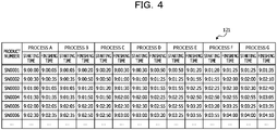
- the history DB 121 is a database that stores a history of the product, which is manufactured by sequential performance of manufacturing by a plurality of processes, in each of the manufacturing processes. That is, the history DB 121 stores the times of starting and finishing the manufacturing in each of the processes as a history with respect to each of the products based on the log data.
- FIG. 4 is a diagram that illustrates one example of the history DB. As illustrated in FIG. 4 , the history DB 121 has items such as "product number" and "starting time” and “finishing time” of each of the processes. The history DB 121 stores one record for each of the products, for example.
- Process number is a number that is uniquely given to each of the products which is manufactured in a factory and is an identifier that identifies the product.
- Startting time is information that indicates the time when manufacturing is started in the corresponding process.
- Fluishing time is information that indicates the time when manufacturing is finished in the corresponding process.
- the example in the first row in FIG. 4 indicates that, as for the product of the product number "SN0001", process A is started at “9:00:00” and finished at “9:00:05”, process B is started at “9:00:05” and finished at “9:00:20”, and process C is started at “9:00:20” and finished at “9:00:30".
- the example in the first row in FIG. 4 then indicates the starting time and the finishing time of each of the processes about processes D to G, similarly.
- the camera definition table 122 stores a camera ID of the camera that corresponds to each of the processes.
- FIG. 5 is a diagram that illustrates one example of the camera definition table. As illustrated in FIG. 5 , the camera definition table 122 has items such as "process”, “camera ID”, “mask”, “X”, “Y”, “width”, and “height”. The camera definition table 122 stores one record for each of the processes, for example.
- Process is an identifier that identifies the process.
- Camera ID is an identifier that identifies the camera which captures an image of each of the processes.
- Mask is information about whether or not the other processes are masked in order to individually display the designated process in a case where the camera captures an image of a plurality of processes.
- “Mask” is indicated as “True” in a case where the other processes are masked but is indicated as “False” in a case where the other processes are not masked.
- X” and “Y” are coordinate information for designating the origin of a displayed rectangle in a case where the "mask” is “True”.
- “Width” and “height” are information for designating the width and height of the displayed rectangle in a case where "mask” is “True”.
- the image DB 123 stores the captured image that is captured by the camera.
- FIG. 6 is a diagram that illustrates one example of the image DB. As illustrated in FIG. 6 , the image DB 123 has items such as "camera ID”, “recording starting date”, “recording finishing date”, and "file name”. The image DB 123 stores one record for each piece of recording of the captured image, for example.
- “Camera ID” is the identifier that identifies the camera which captures an image of each of the processes.
- Recording starting date is information that indicates the recording starting date of the captured image.
- Recording finishing date is information that indicates the recording finishing date of the captured image.
- "File name” is information that indicates a file name of the captured image that is stored in the storage unit 120. "File name” is decided based on the camera ID and the recording starting date or the recording finishing date, for example.
- the example in the first row in FIG. 6 indicates that, as for the camera ID "camera C1", the file name of the captured image for which recording is started at "2015/7/10 8:55" and recording is finished at "2015/7/10 19:05” is "C1-20150710.mp4". That is, the image DB 123 may specify the file of the desired captured image based on the camera ID and the date in a case where the captured image is searched for. Note that the captured image may be a moving image, may be a still image, or may include
- a central processing unit CPU
- a micro processing unit MPU
- the control unit 130 is thereby realized.
- the control unit 130 may be realized by an integrated circuit such as an application specific integrated circuit (ASIC) or a field programmable gate array (FPGA), for example.
- the control unit 130 has a graph display unit 131, a specifying unit 132, and an image display unit 133 and realizes or executes functions and operation of information processing, which are described in the following. Note that an internal configuration of the control unit 130 is not limited to the configuration illustrated in FIG.
- the line segment that corresponds to each of the products is also expressed as trace graph, and the whole graph that includes the respective time axes of the processes and the trace graphs which correspond to the products is expressed as time line graph.
- the graph display unit 131 refers to the history DB 121 and generates the time line graph in a case where the operation information for displaying the display screen that displays the manufacturing statuses is input from the operation unit 112. That is, the graph display unit 131 generates the time line graph that represents the elapsed time from the start to the finish of each manufacturing process of the plurality of manufacturing processes based on the information of the starting times and the finishing times of the manufacturing processes. Further, the graph display unit 131 causes the display unit 111 to display the generated time line graph in a state where the plurality of manufacturing processes are divided into each of manufacturing processes in the execution order, while the time axes are aligned in the same direction.
- the graph display unit 131 acquires the starting time and the finishing time of each of the products in each of the processes in the history DB 121.
- the graph display unit 131 generates the time axes P1 to P8 that indicate the elapsed times of the respective processes and generates the line segment (trace graph) that connects the time axes for each of the product.
- the graph display unit 131 generates the time axes such that the directions of the time axes go along the time order from the upper side toward the lower side of the time line graph, for example.
- a portion between the time axes corresponds to each of the processes.
- the portion between the time axes P1 and P2 indicates the time requested for process A.
- the graph display unit 131 similarly generates the line segment for each of the products.
- the graph display unit 131 arranges the time axes P1 to P8 and processes A to G in the execution order of the processes, that is, in the order of processes A to G in the examples in FIG. 2 and FIG. 3 .
- the graph display unit 131 generates the display screen that includes the time line graph in which the processes, the time axes, and the line segments are arranged, outputs the generated display screen to the display unit 111, and causes the display unit 111 to display the generated display screen.
- the display screen includes regions for displaying the time line graph and the captured images by the cameras. Further, the graph display unit 131 outputs the generated display screen to the specifying unit 132 and the image display unit 133.
- the specifying unit 132 specifies the captured image based on the cursor position information of the operation information that is input from the operation unit 112. That is, the specifying unit 132 specifies the captured image that corresponds to the manufacturing process which corresponds to the designated position based on the cursor position information among the captured images of the plurality of manufacturing processes that are stored in the image DB 123 in accordance with the designated position on the displayed time line graph.
- the specifying unit 132 compares the cursor position information with the coordinates on the display screen and assesses whether or not the line segment is selected by a click operation. In a case where the line segment is not selected, the specifying unit 132 executes usual mode processing. As the usual mode processing, the specifying unit 132 first calculates a display designation date based on a pointed position that is indicated by the cursor position information. Further, the specifying unit 132 specifies a display designation process based on the pointed position. Note that the pointed position is the pointed position that is indicated by a touch position in a case where the operation unit 112 is a touch panel.
- the specifying unit 132 assesses whether or not the pointed position is on any process based on the calculated display designation date and the specified display designation process. In a case where the pointed position is not on any process, the specifying unit 132 refers to the image DB 123, acquires the captured images by all the cameras on the display designation date, and outputs the acquired captured images to the image display unit 133.
- the specifying unit 132 refers to the camera definition table 122 and acquires the camera ID of the camera that corresponds to the process on which the pointed position is, that is, the camera ID of a display designation camera.
- the specifying unit 132 assesses which of emphasis or individual display of display methods is selected based on the selection situation of an emphasis button and an individual display button that are provided on the display screen.
- the specifying unit 132 refers to the image DB 123, acquires the captured images by all the cameras on the display designation date, and outputs the acquired captured images to the image display unit 133. Further, the specifying unit 132 outputs, to the image display unit 133, an emphasis instruction for emphatically displaying a display frame of the captured image that corresponds to the acquired camera ID.
- the specifying unit 132 refers to the image DB 123, acquires the captured image on the display designation date, which corresponds to the acquired camera ID, and outputs the acquired captured image to the image display unit 133. Further, the specifying unit 132 refers to the camera definition table 122 and assesses whether or not the mask item of the acquired camera ID is "True". In a case where the mask item of the acquired camera ID is "True”, the specifying unit 132 outputs, to the image display unit 133, a masking instruction for masking the other processes than the process that corresponds to the acquired camera ID.
- the specifying unit 132 decides the size and position of the mask based on the items of "X", “Y”, “width”, and “height" of the camera definition table 122. In a case where the mask item of the acquired camera ID is not "True", the specifying unit 132 does not output the masking instruction. Note that in a case where the emphasis or the individual display is selected, the specifying unit 132 may set the display regions of the captured images as different regions between the emphasis and the individual display or may perform the display in the same region while the emphasis and the individual display are switched.
- the specifying unit 132 executes similar processing to a case where the emphasis is selected for the region that displays the captured images by all the cameras. Further, the specifying unit 132 executes similar processing to a case where the individual display is selected for the region that displays the captured image for the individual display. That is, the case where both of the emphasis and the individual display are selected is a case where the captured images are displayed in different regions for the emphasis and the individual display.
- FIG. 7 is a diagram that illustrates one example of the display screen in the usual mode.
- a display screen 21 is one example of the display screen in the usual mode and has a region 22 that displays the time line graph, a region 23 that displays the captured images by all the cameras, and a region 24 that individually displays the captured image by the camera which corresponds to the process corresponding to the pointed position.
- the region 23 for example, in a case where four cameras are present, the region 23 is divided into four regions, and the captured images that correspond to the cameras are displayed in the respective regions.
- the display screen 21 has a usual mode button 25 and a selection mode button 26 for selecting an action mode.
- the display screen 21 has an emphasis button 27 and an individual display button 28 for selecting the display method.
- the emphasis and the individual display are not performed, but the captured images by all the cameras are displayed in the region 24 for the individual display, similarly to the region 23.
- the captured images displayed in this case are the captured images at time to that is indicated by a line 30 which corresponds to the pointed position by the cursor 29.
- FIG. 8 is a diagram that illustrates another example of the display screen in the usual mode.
- the cursor 29 is present on process C, and an icon 32, which indicates the target of the emphasis and the individual display, points the same position as the cursor 29.
- the captured images at time t 1 that is indicated by the line 30 which corresponds to the positions of the cursor 29 and the icon 32 are displayed in the region 23 and the region 24.
- a captured image 33 by the camera C2 that corresponds to process C is emphatically displayed by performing thickening, coloring, or the like of the display frame, for example.
- a captured image 34 by the camera C2 is individually displayed. Note that the region 24 may be emphatically displayed by performing thickening, coloring, or the like of the display frame in a case of the individual display.
- FIG. 9 is a diagram that illustrates another example of the display screen in the usual mode.
- the cursor 29 is present on a line segment 36 of process C, and the icon 32 points the same position as the cursor 29.
- the line segment 36 is displayed in a different color from the other line segments, for example, in order to indicate a fact the line segment 36 is pointed by the cursor 29.
- the captured images at time t 2 that is indicated by a line 37 which corresponds to the positions of the cursor 29 and the icon 32 are displayed in the region 23 and the region 24.
- a captured image 38 by the camera C2 that corresponds to process C is emphatically displayed by performing thickening, coloring, or the like of the display frame, for example.
- an image of the product that corresponds to the line segment 36 is captured.
- a captured image 39 by the camera C2 is individually displayed.
- an image of the product that corresponds to the line segment 36 is captured.
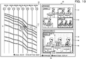
- FIG. 10 is a diagram that illustrates another example of the display screen in the usual mode.
- the cursor 29 is present on a line segment 41 of process E, and the icon 32 points the same position as the cursor 29.
- the line segment 41 is displayed in a different color from the other line segments, for example, in order to indicate a fact the line segment 41 is pointed by the cursor 29.
- the captured images at time t 3 that is indicated by a line 42 which corresponds to the positions of the cursor 29 and the icon 32 are displayed in the region 23 and the region 24.
- a captured image 43 by the camera C4 that corresponds to process E is emphatically displayed by performing thickening, coloring, or the like of the display frame, for example.
- an image of the product that corresponds to the line segment 41 is captured.
- a captured image 44 by the camera C4 is individually displayed.
- a mask 45 is displayed so as to mask other portions than a region 46 that corresponds to process E such that process E and the product that corresponds to the line segment 41 may easily be distinguished.
- the specifying unit 132 executes selection mode processing.
- the specifying unit 132 first calculates the display designation date based on the pointed position that is indicated by the cursor position information.
- the display designation process is specified by selection of the line segment.
- the specifying unit 132 assesses whether or not the display designation date is within all process times of the selected product. That is, the specifying unit 132 assesses whether or not the display designation date is between the time of the time axis P1 and the time of the time axis P8 of the line segment that corresponds to the selected product.
- a selection mode is canceled in a case where the selected line segment or a portion off the line segment is clicked. Further, in the selection mode, the clicked line segment is selected in a case where the other line segment is clicked while the line segment is selected.
- the specifying unit 132 In a case where the display designation date is not within all the process times of the selected product, the specifying unit 132 outputs, to the image display unit 133, an out-of-range instruction that displays a fact that the display designation date is out of range in the region for displaying the captured image. In a case where the display designation date is within all the process times of the selected product, the specifying unit 132 sets the intersection point between the line segment of the selected product and the line that indicates the display designation date as a display target and specifies the display designation process. Here, the cursor may be in another portion than the line segment of the selected product.
- the specifying unit 132 refers to the camera definition table 122 and acquires the camera ID of the display designation camera that corresponds to the process in which the intersection point as the display target is.
- the specifying unit 132 assesses which of the emphasis or the individual display of the display methods is selected based on the selection situation of the emphasis button and the individual display button that are provided on the display screen.
- the processing based on the assessment about which of the emphasis or the individual display of the display methods is selected is similar to the cases of the usual mode, and a description thereof is thus not made.
- the specifying unit 132 assesses whether or not the operation information for finishing the display is input from the operation unit 112 while the display screen of the time line graph and the captured images are displayed. In a case where the operation information for finishing the display is not input, the specifying unit 132 continues to display the display screen of the time line graph and the captured images and executes the usual mode processing or the selection mode processing based on presence or absence of selection of the line segment. In a case where the operation information for finishing the display is input, the specifying unit 132 outputs, to the image display unit 133, a finishing instruction that finishes the display of the display screen of the time line graph and the captured images.
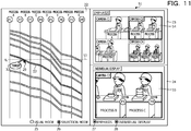
- FIG. 11 is a diagram that illustrates one example of the display screen in the selection mode.
- a display screen 51 similarly to the display screen in the usual mode, a display screen 51 has the region 22 that displays the time line graph, the region 23 that displays the captured images by all the cameras, and the region 24 that individually displays the captured image by the camera which corresponds to the process corresponding to the pointed position.
- the region 23 for example, similarly to the display screen in the usual mode, in a case where four cameras are present, the region 23 is divided into four regions, and the captured images that correspond to the cameras are displayed in the respective regions.
- the display screen 51 similarly to the display screen in the usual mode, the display screen 51 has the usual mode button 25 and the selection mode button 26 for selecting the action mode. Note that in the display screen 51, the selection mode button 26 is selected.
- the display screen 51 similarly to the display screen in the usual mode, has the emphasis button 27 and the individual display button 28 for selecting the display method.
- the cursor 29 is present on process B, and the icon 32, which indicates the target of the emphasis and the individual display, points the same position as the cursor 29.
- a line segment 52 is displayed in a different color from the other line segments, for example, in order to indicate a fact the line segment 52 is clicked and selected by the cursor 29.
- the captured images at time t 4 that is indicated by a line 53 which corresponds to the positions of the cursor 29 and the icon 32 are displayed in the region 23 and the region 24. Note that the positions of the cursor 29 and the icon 32 are a first designated position.
- a captured image 54 by the camera C2 that corresponds to process B is emphatically displayed by performing thickening, coloring, or the like of the display frame, for example.
- the captured image 54 an image of the product that corresponds to the line segment 52 is captured.
- a captured image 55 by the camera C2 is individually displayed.
- the captured image 55 similarly to the captured image 54, an image of the product that corresponds to the line segment 52 is captured.
- the region 24 may be emphatically displayed by performing thickening, coloring, or the like of the display frame in a case of the individual display.
- FIG. 12 is a diagram that illustrates another example of the display screen in the selection mode.
- the cursor 29 is positioned in a different region from the position of the line segment 52 that is specified by the first designated position in FIG. 11 .
- the position of the cursor 29 is a second designated position that is pointed.
- the line 53 moves in the time axis direction in response to the movement of the cursor 29.
- the icon 32 moves on the line segment 52 and indicates the intersection point between the line segment 52 on process D and the line 53.
- the line segment 52 is displayed in a different color from the other line segments, for example, in order to indicate a fact the line segment 52 is selected.
- the captured images at time t 5 that is indicated by the line 53 which corresponds to the position of the icon 32 are displayed in the region 23 and the region 24.
- a captured image 57 by the camera C3 that corresponds to process D is emphatically displayed by performing thickening, coloring, or the like of the display frame, for example.
- an image of the product that corresponds to the line segment 52 is captured.
- a captured image 58 by the camera C3 is individually displayed.
- an image of the product that corresponds to the line segment 52 is captured.
- FIG. 13 is a diagram that illustrates another example of the display screen in the selection mode.
- the cursor 29 is positioned in a different region from the position of the line segment 52 that is specified by the first designated position in FIG. 11 .
- the position of the cursor 29 is the second designated position that is pointed.
- the line 53 moves in the time axis direction in response to the movement of the cursor 29.
- the icon 32 moves on the line segment 52 and indicates the intersection point between the line segment 52 on process E and the line 53.
- the line segment 52 is displayed in a different color from the other line segments, for example, in order to indicate a fact the line segment 52 is selected.
- the captured images at time t 6 that is indicated by the line 53 which corresponds to the position of the icon 32 are displayed in the region 23 and the region 24.
- a captured image 60 by the camera C4 that corresponds to process E is emphatically displayed by performing thickening, coloring, or the like of the display frame, for example.
- an image of the product that corresponds to the line segment 52 is captured.
- a captured image 61 by the camera C4 is individually displayed.
- the captured image 61 similarly to the captured image 60, an image of the product that corresponds to the line segment 52 is captured.
- a mask 62 is displayed so as to mask other portions than a region 63 that corresponds to process E such that process E and the product that corresponds to the line segment 52 may easily be distinguished.
- FIG. 14 is a diagram that illustrates another example of the display screen in the selection mode.
- the cursor 29 in a display screen 64, the cursor 29 is positioned in a different region from the position of the line segment 52 that is specified by the first designated position in FIG. 11 .
- the position of the cursor 29 is the second designated position that is pointed.
- the line 53 moves in the time axis direction in response to the movement of the cursor 29.
- the cursor 29 and the line 53 are out of the range of the starting time and the finishing time of the line segment 52. Note that the line segment 52 is displayed in a different color from the other line segments, for example, in order to indicate a fact the line segment 52 is selected.
- the captured images at time t 7 that is indicated by the line 53 are not displayed because the line 53 is out of the range of the starting time and the finishing time of the line segment 52.
- display 65 that indicates out of range is displayed.
- display 66 that indicates out of range is displayed.
- FIG. 15 is a diagram that illustrates one example of an additional assessment region in selection of the line segment.
- regions 67a and 67b that are adjacent to the line segment 67 are set as the additional assessment regions.
- the regions 67a and 67b are set as the widths to distances d that are equivalent distances from the line segment 67, for example.
- the interval between the line segments is distance 2d or less in a portion.
- the middle of the line segment 68 and the line segment 69 is set as the border between the region 68b and a region 69a.
- regions 69a and 69b that are adjacent to the line segment 69 are set as the additional assessment regions.
- the display screen is input from the graph display unit 131 to the image display unit 133.
- the image display unit 133 updates the display screen such that the captured image is displayed in the region for displaying the captured image by the camera in the display screen.
- the image display unit 133 updates the display screen such that the display frame of the captured image that corresponds to the emphasis instruction is emphatically displayed.
- the image display unit 133 refers to the camera definition table 122 and updates the display screen such that the mask that corresponds to the masking instruction is drawn.
- the image display unit 133 updates the display screen such that the display that indicates out of range is performed in the region for displaying the captured image by the camera in the display screen.
- the image display unit 133 finishes the display of the display screen.
- FIG. 16 is a flowchart that illustrates one example of management processing of the embodiment.
- the graph display unit 131 refers to the history DB 121 and generates the time line graph in a case where the operation information for displaying the display screen that displays the manufacturing statuses is input from the operation unit 112 (step S1).
- the graph display unit 131 generates the display screen that includes the generated time line graph, outputs the generated display screen to the display unit 111, and causes the display unit 111 to display the generated display screen. Further, the graph display unit 131 outputs the generated display screen to the specifying unit 132 and the image display unit 133.
- the specifying unit 132 compares the cursor position information of the operation information input from the operation unit 112 with the coordinates on the display screen and assesses whether or not the line segment is selected by the click operation (step S2). In a case where the line segment is not selected (step S2: negative), the specifying unit 132 executes the usual mode processing (step S3).
- FIG. 17 is a flowchart that illustrates one example of the usual mode processing.
- the specifying unit 132 first calculates the display designation date based on the pointed position that is indicated by the cursor position information (step S31). Further, the specifying unit 132 specifies the display designation process based on the pointed position (step S32).
- the specifying unit 132 assesses whether or not the pointed position is on any process based on the calculated display designation date and the specified display designation process (step S33). In a case where the pointed position is not on any process (step S33: negative), the specifying unit 132 refers to the image DB 123, acquires the captured images by all the cameras on the display designation date, and outputs the acquired captured images to the image display unit 133. In a case where the captured images are input from the specifying unit 132, the image display unit 133 updates the display screen such that the captured images are displayed in the regions for displaying the captured images by the cameras in the display screen (step S34), and the usual mode processing returns to the original processing.
- the specifying unit 132 acquires the camera ID of the display designation camera from the camera definition table 122 (step S35). The specifying unit 132 assesses which of the emphasis or the individual display of the display methods is selected based on the selection situation of the emphasis button and the individual display button that are provided on the display screen (step S36). In a case where the emphasis is selected (step S36: emphasis), the specifying unit 132 refers to the image DB 123, acquires the captured images by all the cameras on the display designation date, and outputs the acquired captured images to the image display unit 133. In a case where the captured image is input from the specifying unit 132, the image display unit 133 updates the display screen such that the captured images are displayed in the region for displaying the captured images by the cameras in the display screen (step S37).
- the specifying unit 132 outputs, to the image display unit 133, the emphasis instruction for emphatically displaying the display frame of the captured image that corresponds to the acquired camera ID.
- the image display unit 133 updates the display screen such that the display frame of the captured image that corresponds to the emphasis instruction is emphatically displayed (step S38), and the usual mode processing returns to the original processing.
- the specifying unit 132 refers to the image DB 123, acquires the captured image on the display designation date, which corresponds to the acquired camera ID, and outputs the acquired captured image to the image display unit 133.
- the image display unit 133 updates the display screen such that the captured image is displayed in the region for displaying the captured image by the camera in the display screen (step S39).
- the specifying unit 132 refers to the camera definition table 122 and assesses whether or not the mask item of the acquired camera ID is "True” (step S40). In a case where the mask item of the acquired camera ID is "True” (step S40: affirmative), the specifying unit 132 outputs, to the image display unit 133, the masking instruction for masking the other processes than the process that corresponds to the acquired camera ID. In a case where the masking instruction is input from the specifying unit 132, the image display unit 133 updates the display screen such that the mask that corresponds to the masking instruction is drawn (step S41), and the usual mode processing returns to the original processing. In a case where the mask item of the acquired camera ID is not "True” (step S40: negative), the specifying unit 132 does not output the masking instruction, and the usual mode processing returns to the original processing.
- the specifying unit 132 executes steps S37 and S38 for the region that displays the captured images by all the cameras (step S42). Further, the specifying unit 132 executes steps S39 to S41 for the region that displays the captured image for the individual display (step S43), and the usual mode processing returns to the original processing. Accordingly, the management apparatus 100 may display the image that corresponds to the designated process by pointing.
- step S4 the specifying unit 132 executes the selection mode processing (step S4).
- the selection mode processing is described by using FIG. 18.
- FIG. 18 is a flowchart that illustrates one example of the selection mode processing.
- the specifying unit 132 first calculates the display designation date based on the pointed position that is indicated by the cursor position information (step S51). The specifying unit 132 assesses whether or not the display designation date is within all the process times of the selected product (step S52). In a case where the display designation date is not within all the process times of the selected product (step S52: negative), the specifying unit 132 outputs, to the image display unit 133, the out-of-range instruction that displays a fact that the display designation date is out of range in the region for displaying the captured image.
- the image display unit 133 updates the display screen such that the display that indicates out of range is performed in the region for displaying the captured image by the camera in the display screen (step S53), and the selection mode processing returns to the original processing.
- the specifying unit 132 sets the intersection point between the line segment of the selected product and the line that indicates the display designation date as the display target and specifies the display designation process (step S54).
- the specifying unit 132 refers to the camera definition table 122 and acquires the camera ID of the display designation camera that corresponds to the process in which the intersection point as the display target is (step S55).
- the specifying unit 132 assesses which of the emphasis or the individual display of the display methods is selected based on the selection situation of the emphasis button and the individual display button that are provided on the display screen (step S56). In a case where the emphasis is selected (step S56: emphasis), the specifying unit 132 refers to the image DB 123, acquires the captured images by all the cameras on the display designation date, and outputs the acquired captured images to the image display unit 133. In a case where the captured images are input from the specifying unit 132, the image display unit 133 updates the display screen such that the captured images are displayed in the region for displaying the captured images by the cameras in the display screen (step S57).
- the specifying unit 132 outputs, to the image display unit 133, the emphasis instruction for emphatically displaying the display frame of the captured image that corresponds to the acquired camera ID.
- the image display unit 133 updates the display screen such that the display frame of the captured image that corresponds to the emphasis instruction is emphatically displayed (step S58), and the selection mode processing returns to the original processing.
- the specifying unit 132 refers to the image DB 123, acquires the captured image on the display designation date, which corresponds to the acquired camera ID, and outputs the acquired captured image to the image display unit 133.
- the image display unit 133 updates the display screen such that the captured image is displayed in the region for displaying the captured image by the camera in the display screen (step S59).
- the specifying unit 132 refers to the camera definition table 122 and assesses whether or not the mask item of the acquired camera ID is "True” (step S60). In a case where the mask item of the acquired camera ID is "True” (step S60: affirmative), the specifying unit 132 outputs, to the image display unit 133, the masking instruction for masking the other processes than the process that corresponds to the acquired camera ID. In a case where the masking instruction is input from the specifying unit 132, the image display unit 133 updates the display screen such that the mask that corresponds to the masking instruction is drawn (step S61), and the selection mode processing returns to the original processing. In a case where the mask item of the acquired camera ID is not "True” (step S60: negative), the specifying unit 132 does not output the masking instruction, and the selection mode processing returns to the original processing.
- the specifying unit 132 executes steps S57 and S58 for the region that displays the captured images by all the cameras (step S62). Further, the specifying unit 132 executes steps S59 to S61 for the region that displays the captured image for the individual display (step S63), and the selection mode processing returns to the original processing. Accordingly, the management apparatus 100 may display the image that corresponds to the process which is selected and thereby designated.
- the specifying unit 132 assesses whether or not the operation information for finishing the display is input from the operation unit 112 (step S5). That is, the specifying unit 132 assesses whether or not the operation information for finishing the display is input from the operation unit 112 while the display screen of the time line graph and the captured images is displayed.
- step S5 negative
- step S5: affirmative the specifying unit 132 outputs, to the image display unit 133, the finishing instruction that finishes the display of the display screen of the time line graph and the captured images.
- the finishing instruction is input from the specifying unit 132
- the image display unit 133 finishes the display of the display screen. Accordingly, the management apparatus 100 may display the image that corresponds to the designated process.
- the management apparatus 100 displays the graph that represents the elapsed time from the start to the finish of each manufacturing process of a plurality of manufacturing processes, based on the information of the starting times and the finishing times of the manufacturing processes, in a state where the plurality of manufacturing processes are divided into each of manufacturing processes in the execution order, while the time axes are aligned in the same direction. Further, the management apparatus 100 specifies the captured image that corresponds to the manufacturing process which corresponds to the designated position among the captured images of the plurality of manufacturing processes that are stored in the image DB 123 in accordance with the designated position on the displayed graph. Further, the management apparatus 100 displays the specified captured image. As a result, the image that corresponds to the designated process may be displayed. Further, it becomes easy to check, by images, the state of the processing time of the whole manufacturing line and the circumstance of the manufacturing performed in a specific process.
- the management apparatus 100 performs the display such that it is possible to distinguish which is the specified captured image among the plurality of captured images. As a result, the captured image of the desired process or product may easily be displayed in a distinguishable manner.
- the graph is displayed with the line segments, and the designated position is in any position on the line segment.
- the correspondence relationship between the designated process and the corresponding image may clearly be displayed.
- the any position on the line segment is based on the designation of the line segment and the designation of the time and corresponds to the position that corresponds to the designated time on the designated line segment.
- the image that corresponds to the designated time on the designated line segment may be displayed.
- the graph is displayed with the line segments, and the designated position is a position on the closest line segment to the pointed position or the touch position that is not on any line segment. As a result, even in a case where the line segment is thin, the line segment may easily be selected.
- the graph is displayed with the line segments. Further, the management apparatus 100 specifies the product related to the manufacturing process that corresponds to the first designated position as any position on the line segment on the graph and, after specifying the product, specifies the captured image that corresponds to the manufacturing process of the specified product in accordance with the time that corresponds to the second designated position on the graph which is different from the first designated position. As a result, the cursor is moved after selection of the line segment, and the captured image of each of the manufacturing processes related to the product of the selected line segment may thereby be displayed.
- the portion that corresponds to the pointed process is displayed by masking processing.
- the masking processing is not performed, but the administrator of the manufacturing process management system may determine the image of which process is the desired image with respect to the captured image in which the image of the plurality of processes is captured. Accordingly, because previous and subsequent circumstances of the product may be displayed, it becomes easier to recognize the situation.
- the selection mode is canceled in a case where the selected line segment or a portion off the line segment is clicked.
- embodiments are not limited to this.
- a radio button of the usual mode that is provided in the display screen is selected, the selection mode is thereby switched to the usual mode, and the selection mode may be canceled.
- the configuration elements of the portions in the illustrations do not necessarily have to be physically configured as the illustrations. That is, specific manners of distribution and integration of the portions are not limited to the manners in the illustrations. All or a portion thereof may be configured by functionally or physically distributing or integrating those by any set in accordance with various kinds of loads, usage condition, and so forth.
- the graph display unit 131 and the image display unit 133 may be integrated.
- the pieces of processing in the illustrations are not limited to the above orders but may simultaneously be carried out or may be carried out while sequences are rearranged in the scope in which processing contents do not contradict.
- all or an arbitrary portion of various kinds of processing functions performed by apparatuses may be executed in a CPU (or a microcomputer such as an MPU or a micro controller unit (MCU)). Further, it is matter of course that all or an arbitrary portion of various kinds of processing functions may be executed on a program that is analyzed and executed by the CPU (or the microcomputer such as the MPU or the MCU) or on hardware by wired logic.
- a CPU or a microcomputer such as an MPU or a micro controller unit (MCU)
- MCU micro controller unit
- FIG. 19 is a diagram that illustrates one example of a computer that executes the manufacturing process management program.
- a computer 200 has a CPU 201 that executes various kinds of computing processing, an input apparatus 202 that accepts data inputs, and a monitor 203. Further, the computer 200 has a medium reading apparatus 204 that reads a program or the like from a storage medium, an interface apparatus 205 for connection with various kinds of apparatuses, and a communication apparatus 206 for connecting with other information processing apparatuses and so forth in a wired or wireless manner. Further, the computer 200 has a RAM 207 that temporarily stores various kinds of information and a hard disk apparatus 208. Further, the apparatuses 201 to 208 are connected with a bus 209.
- the hard disk apparatus 208 stores the manufacturing process management program that has similar functions to the processing units as the graph display unit 131, the specifying unit 132, and the image display unit 133, which are illustrated in FIG. 1 . Further, the hard disk apparatus 208 stores various kinds of data for realizing the history DB 121, the camera definition table 122, the image DB 123, and the manufacturing process management program.
- the input apparatus 202 accepts inputs of various kinds of information such as operation information and management information from an administrator of the computer 200, for example.
- the monitor 203 displays the display screen, a screen of the management information, and various kinds of screens to the administrator of the computer 200, for example.
- the interface apparatus 205 is connected with a printing apparatus or the like, for example.
- the communication apparatus 206 has a similar function to the communication unit 110 illustrated in FIG. 1 , is connected with a network that is not illustrated, and interchanges various kinds of information with various kinds of apparatuses, for example.
- the CPU 201 reads out each program stored in the hard disk apparatus 208, expands each of the programs in the RAM 207, executes the program, and thereby performs various kinds of processing. Further, those programs may cause the computer 200 to function as the graph display unit 131, the specifying unit 132, and the image display unit 133, which are illustrated in FIG. 1 .
- the above manufacturing process management program does not necessarily have to be stored in the hard disk apparatus 208.
- the computer 200 may read out and execute the program that is stored in a storage medium which is readable by the computer 200.
- the storage medium that is readable by the computer 200 corresponds to a portable recording medium such as a CD-ROM, a DVD disk, or a universal serial bus (USB) memory, a semiconductor memory such as a flash memory, a hard disk drive, or the like, for example.
- this manufacturing process management program is stored in apparatuses that are connected with a public line, the Internet, a LAN, and so forth, and the computer 200 may thereby read out the manufacturing process management program from those and execute the manufacturing process management program.
Landscapes
- Engineering & Computer Science (AREA)
- Business, Economics & Management (AREA)
- Human Resources & Organizations (AREA)
- General Physics & Mathematics (AREA)
- Physics & Mathematics (AREA)
- Strategic Management (AREA)
- Economics (AREA)
- Theoretical Computer Science (AREA)
- Marketing (AREA)
- Educational Administration (AREA)
- Tourism & Hospitality (AREA)
- General Business, Economics & Management (AREA)
- Entrepreneurship & Innovation (AREA)
- Development Economics (AREA)
- Quality & Reliability (AREA)
- Manufacturing & Machinery (AREA)
- Signal Processing (AREA)
- Multimedia (AREA)
- General Health & Medical Sciences (AREA)
- Operations Research (AREA)
- Health & Medical Sciences (AREA)
- Game Theory and Decision Science (AREA)
- Primary Health Care (AREA)
- General Engineering & Computer Science (AREA)
- Automation & Control Theory (AREA)
- General Factory Administration (AREA)
- Management, Administration, Business Operations System, And Electronic Commerce (AREA)
- Image Generation (AREA)
- User Interface Of Digital Computer (AREA)
- Image Processing (AREA)
Abstract
Description
- The present invention relates to a manufacturing process management system, a manufacturing process management method, and a manufacturing process management program.
- Accumulation and utilization of data accompanying activities of a company have been performed. For example, data such as action logs of a manufacturing apparatus in an assembly line of a product are accumulated and utilized for an improvement in a production process. Further, it has been suggested that the flow of product is plotted on a graph expressed by processes and times and the manufacturing statuses in the processes are thereby visualized and displayed. An example of related art is disclosed in Japanese Laid-open Patent Publication No.
2015-075795 - However, in a case where a user views the graph that visualizes the manufacturing statuses of the processes and notices the presence of the process in which a further check is requested, the user may desire to check how work in the process is performed.
- One aspect of the present invention provides a manufacturing process management system, a manufacturing process management method, and a manufacturing process management program that may display an image which corresponds to a designated process.
- In one embodiment, in a manufacturing process management system that displays a manufacturing status of a product which is manufactured through a plurality of manufacturing processes, the manufacturing process management system includes at least a management apparatus. The management apparatus has a graph display unit, a specifying unit, and an image display unit. A graph display unit displays a graph that represents an elapsed time from a start to a finish of each manufacturing process of the plurality of manufacturing processes, based on information of starting times and finishing times of the manufacturing processes, in a state where the plurality of manufacturing processes are divided into each of manufacturing processes in an execution order, while time axes are aligned in a same direction. A specifying unit specifies a captured image that corresponds to the manufacturing process which corresponds to a designated position among captured images of the plurality of manufacturing processes which are stored in a storage unit in accordance with the designated position on the displayed graph. The image display unit displays the specified captured image.
- An image that corresponds to a designated process may be displayed.
-
-
FIG. 1 is a block diagram that illustrates one example of a configuration of a manufacturing process management system of an embodiment. -
FIG. 2 is a diagram that illustrates one example of manufacturing processes. -
FIG. 3 is a diagram that illustrates one example of a graph which represents statuses of manufacturing processes. -
FIG. 4 is a diagram that illustrates one example of a history DB. -
FIG. 5 is a diagram that illustrates one example of a camera definition table. -
FIG. 6 is a diagram that illustrates one example of an image DB. -
FIG. 7 is a diagram that illustrates one example of a display screen in a usual mode. -
FIG. 8 is a diagram that illustrates another example of the display screen in the usual mode. -
FIG. 9 is a diagram that illustrates another example of the display screen in the usual mode. -
FIG. 10 is a diagram that illustrates another example of the display screen in the usual mode. -
FIG. 11 is a diagram that illustrates one example of a display screen in a selection mode. -
FIG. 12 is a diagram that illustrates another example of the display screen in the selection mode. -
FIG. 13 is a diagram that illustrates another example of the display screen in the selection mode. -
FIG. 14 is a diagram that illustrates another example of the display screen in the selection mode. -
FIG. 15 is a diagram that illustrates one example of an additional assessment region in selection of a line segment. -
FIG. 16 is a flowchart that illustrates one example of management processing of the embodiment. -
FIG. 17 is a flowchart that illustrates one example of usual mode processing. -
FIG. 18 is a flowchart that illustrates one example of selection mode processing. -
FIG. 19 is a diagram that illustrates one example of a computer which executes a manufacturing process management program. - An embodiment of a manufacturing process management system, a manufacturing process management method, and a manufacturing process management program, which are disclosed by this application, is hereinafter be described in detail with reference to drawings. Note that the disclosed techniques are not limited by this embodiment. Further, the following embodiment may appropriately be combined in the scope in which a contradiction does not occur.
-
FIG. 1 is a block diagram that illustrates one example of a configuration of the manufacturing process management system of the embodiment. A manufacturingprocess management system 1 illustrated inFIG. 1 has amanagement apparatus 100. The manufacturingprocess management system 1 may include a control apparatus of each manufacturing process, a control apparatus of a machine tool, and various kinds of examination apparatuses for a temperature examination and so forth, for example, other than themanagement apparatus 100. Themanagement apparatus 100 may acquire log data from various kinds of apparatuses. Further, the manufacturingprocess management system 1 may include a terminal apparatus for an administrator. Themanagement apparatus 100 and various kinds of apparatuses are connected so as to be capable of mutual communication via a network, which is not illustrated. Note that in the following description, a case where various kinds of information of an assembly line of a product are acquired as log data. - The
management apparatus 100 of the manufacturingprocess management system 1 illustrated inFIG. 1 displays a manufacturing status of a product that is manufactured through a plurality of manufacturing processes. The displayed manufacturing statuses are a graph based on information of starting times and finishing times of the manufacturing processes based on the log data and captured images in which the manufacturing processes are captured, for example. Note that in the following description, the manufacturing process may simply be referred to as process. Themanagement apparatus 100 displays a graph that represents the elapsed time from the start to the finish of each manufacturing process of a plurality of manufacturing processes, based on the information of the starting times and the finishing times of the manufacturing processes, in a state where the plurality of manufacturing processes are divided into each of manufacturing processes in the execution order, while the time axes are aligned in the same direction. Themanagement apparatus 100 specifies the captured image that corresponds to the manufacturing process which corresponds to a designated position among captured images of the plurality of manufacturing processes that are stored in a storage unit in accordance with the designated position on the displayed graph. Themanagement apparatus 100 displays the specified captured image. Accordingly, themanagement apparatus 100 may display the image that corresponds to the designated process. - One example of the manufacturing processes in this embodiment is described by using
FIG. 2. FIG. 2 is a diagram that illustrates one example of the manufacturing processes. As illustrated inFIG. 2 , the manufacturing processes have seven processes of process A to process G. In each of the processes, for example, a worker carries out assembly work for the product. In the example inFIG. 2 , the starting and finishing timings of the respective processes are denoted by P1 to P8. In this embodiment, for example, because the product flows on a manufacturing line, a description is made on an assumption that the finishing timing of process A is simultaneous with the starting timing of process B, for example. Note that in a case where the product is moved between the processes, the starting and finishing timings of the processes may be different timings. Further, in the example of the manufacturing processes inFIG. 2 , a camera C1 that captures an image of process A, a camera C2 that captures an image of process B and process C, a camera C3 that captures an image of process D, and a camera C4 that captures an image of processes E to G are placed. - One example of the graph that represents the statuses of the manufacturing processes in this embodiment is described by using
FIG. 3. FIG. 3 is a diagram that illustrates one example of the graph which represents the statuses of the manufacturing processes. As illustrated inFIG. 3 , the graph that represents the statuses of the manufacturing processes (hereinafter referred to as time line graph) corresponds to the manufacturing processes illustrated inFIG. 2 and is the graph that indicates the elapsed times in the respective processes. A time axis P1 of the time line graph illustrated inFIG. 3 corresponds to the starting timing P1 of process A inFIG. 2 . Further, a time axis P2 of the time line graph illustrated inFIG. 3 corresponds to the finish timing of process A and the starting timing P2 of process B inFIG. 2 . Then, similarly, time axes P3 to P8 of the time line graph illustrated inFIG. 3 correspond to the starting and finishing timings P3 to P8 of the respective processes inFIG. 2 . Further, the upper portion of the time line graph inFIG. 3 indicates the relationships between the cameras C1 to C4 and processes A to G, which are illustrated inFIG. 2 . Further, in the time line graph, the flow of the product is indicated by line segments that connect the processes. The line segment is expressed as trace graph because the line segment traces the flow of the product in the manufacturing processes. - Next, returning to
FIG. 1 , a configuration of themanagement apparatus 100 is described. As illustrated inFIG. 1 , themanagement apparatus 100 has acommunication unit 110, adisplay unit 111, anoperation unit 112, astorage unit 120, and acontrol unit 130. Note that themanagement apparatus 100 may have various kinds of function units, which a known computer has, other than the function units illustrated inFIG. 1 , for example, function units such as various kinds of input devices and sound output devices. - The
communication unit 110 is realized by a network interface card (NIC), for example. Thecommunication unit 110 is a communication interface that is connected with various kinds of apparatuses via a network, which is not illustrated, in a wired or wireless manner and that conducts communication of information among the various kinds of apparatuses. Thecommunication unit 110 receives the log data from the various kinds of apparatuses. Thecommunication unit 110 outputs the received log data to thecontrol unit 130. - The
display unit 111 is a display device for displaying various kinds of information. Thedisplay unit 111 is realized as a display device by a liquid crystal display or the like, for example. Thedisplay unit 111 displays various kinds of screens such as display screens that are input from thecontrol unit 130. - The
operation unit 112 is an input device that accepts various kinds of operations from the administrator of the manufacturingprocess management system 1. Theoperation unit 112 is realized as an input device by a keyboard, a mouse, or the like, for example. Theoperation unit 112 outputs an operation input by the administrator as operation information to thecontrol unit 130. The operation information includes position information on the display screen in a pointing operation to bring a mouse cursor to a displayed object (hereinafter also referred to as cursor position information), for example. Note that theoperation unit 112 may be realized as the input device by a touch panel or the like, and the display device of thedisplay unit 111 and the input device of theoperation unit 112 may be integrated. - The
storage unit 120 is realized by a storage apparatus such as a random access memory (RAM), a semiconductor memory element such as a flash memory, a hard disk, or an optical disk, for example. Thestorage unit 120 has ahistory database 121, a camera definition table 122, and animage database 123. Note that in the following description, database is expressed while abbreviated as DB. Further, thestorage unit 120 stores information that is used in processing in thecontrol unit 130. - The
history DB 121 is a database that stores a history of the product, which is manufactured by sequential performance of manufacturing by a plurality of processes, in each of the manufacturing processes. That is, thehistory DB 121 stores the times of starting and finishing the manufacturing in each of the processes as a history with respect to each of the products based on the log data.FIG. 4 is a diagram that illustrates one example of the history DB. As illustrated inFIG. 4 , thehistory DB 121 has items such as "product number" and "starting time" and "finishing time" of each of the processes. Thehistory DB 121 stores one record for each of the products, for example. - "Product number" is a number that is uniquely given to each of the products which is manufactured in a factory and is an identifier that identifies the product. "Starting time" is information that indicates the time when manufacturing is started in the corresponding process. "Finishing time" is information that indicates the time when manufacturing is finished in the corresponding process. The example in the first row in
FIG. 4 indicates that, as for the product of the product number "SN0001", process A is started at "9:00:00" and finished at "9:00:05", process B is started at "9:00:05" and finished at "9:00:20", and process C is started at "9:00:20" and finished at "9:00:30". The example in the first row inFIG. 4 then indicates the starting time and the finishing time of each of the processes about processes D to G, similarly. - Returning to the description of
FIG. 1 , the camera definition table 122 stores a camera ID of the camera that corresponds to each of the processes.FIG. 5 is a diagram that illustrates one example of the camera definition table. As illustrated inFIG. 5 , the camera definition table 122 has items such as "process", "camera ID", "mask", "X", "Y", "width", and "height". The camera definition table 122 stores one record for each of the processes, for example. - "Process" is an identifier that identifies the process. "Camera ID" is an identifier that identifies the camera which captures an image of each of the processes. "Mask" is information about whether or not the other processes are masked in order to individually display the designated process in a case where the camera captures an image of a plurality of processes. "Mask" is indicated as "True" in a case where the other processes are masked but is indicated as "False" in a case where the other processes are not masked. "X" and "Y" are coordinate information for designating the origin of a displayed rectangle in a case where the "mask" is "True". "Width" and "height" are information for designating the width and height of the displayed rectangle in a case where "mask" is "True".
- Returning to the description of
FIG. 1 , theimage DB 123 stores the captured image that is captured by the camera.FIG. 6 is a diagram that illustrates one example of the image DB. As illustrated inFIG. 6 , theimage DB 123 has items such as "camera ID", "recording starting date", "recording finishing date", and "file name". Theimage DB 123 stores one record for each piece of recording of the captured image, for example. - "Camera ID" is the identifier that identifies the camera which captures an image of each of the processes. "Recording starting date" is information that indicates the recording starting date of the captured image. "Recording finishing date" is information that indicates the recording finishing date of the captured image. "File name" is information that indicates a file name of the captured image that is stored in the
storage unit 120. "File name" is decided based on the camera ID and the recording starting date or the recording finishing date, for example. The example in the first row inFIG. 6 indicates that, as for the camera ID "camera C1", the file name of the captured image for which recording is started at "2015/7/10 8:55" and recording is finished at "2015/7/10 19:05" is "C1-20150710.mp4". That is, theimage DB 123 may specify the file of the desired captured image based on the camera ID and the date in a case where the captured image is searched for. Note that the captured image may be a moving image, may be a still image, or may include sound. - Returning to the description of
FIG. 1 , for example, a central processing unit (CPU), a micro processing unit (MPU), or the like executes a program stored in an internal storage apparatus with a RAM serving as a work area, and thecontrol unit 130 is thereby realized. Further, thecontrol unit 130 may be realized by an integrated circuit such as an application specific integrated circuit (ASIC) or a field programmable gate array (FPGA), for example. Thecontrol unit 130 has agraph display unit 131, a specifyingunit 132, and animage display unit 133 and realizes or executes functions and operation of information processing, which are described in the following. Note that an internal configuration of thecontrol unit 130 is not limited to the configuration illustrated inFIG. 1 but may be another configuration as long as the configuration performs information processing described later. Note that in the following description, the line segment that corresponds to each of the products is also expressed as trace graph, and the whole graph that includes the respective time axes of the processes and the trace graphs which correspond to the products is expressed as time line graph. - The
graph display unit 131 refers to thehistory DB 121 and generates the time line graph in a case where the operation information for displaying the display screen that displays the manufacturing statuses is input from theoperation unit 112. That is, thegraph display unit 131 generates the time line graph that represents the elapsed time from the start to the finish of each manufacturing process of the plurality of manufacturing processes based on the information of the starting times and the finishing times of the manufacturing processes. Further, thegraph display unit 131 causes thedisplay unit 111 to display the generated time line graph in a state where the plurality of manufacturing processes are divided into each of manufacturing processes in the execution order, while the time axes are aligned in the same direction. - The
graph display unit 131 acquires the starting time and the finishing time of each of the products in each of the processes in thehistory DB 121. Thegraph display unit 131 generates the time axes P1 to P8 that indicate the elapsed times of the respective processes and generates the line segment (trace graph) that connects the time axes for each of the product. Note that thegraph display unit 131 generates the time axes such that the directions of the time axes go along the time order from the upper side toward the lower side of the time line graph, for example. In the time line graph, a portion between the time axes corresponds to each of the processes. In the example inFIG. 3 , the portion between the time axes P1 and P2 indicates the time requested for process A. Thegraph display unit 131 similarly generates the line segment for each of the products. - The
graph display unit 131 arranges the time axes P1 to P8 and processes A to G in the execution order of the processes, that is, in the order of processes A to G in the examples inFIG. 2 andFIG. 3 . Thegraph display unit 131 generates the display screen that includes the time line graph in which the processes, the time axes, and the line segments are arranged, outputs the generated display screen to thedisplay unit 111, and causes thedisplay unit 111 to display the generated display screen. Note that the display screen includes regions for displaying the time line graph and the captured images by the cameras. Further, thegraph display unit 131 outputs the generated display screen to the specifyingunit 132 and theimage display unit 133. - In a case where the display screen is input from the
graph display unit 131, the specifyingunit 132 specifies the captured image based on the cursor position information of the operation information that is input from theoperation unit 112. That is, the specifyingunit 132 specifies the captured image that corresponds to the manufacturing process which corresponds to the designated position based on the cursor position information among the captured images of the plurality of manufacturing processes that are stored in theimage DB 123 in accordance with the designated position on the displayed time line graph. - The specifying
unit 132 compares the cursor position information with the coordinates on the display screen and assesses whether or not the line segment is selected by a click operation. In a case where the line segment is not selected, the specifyingunit 132 executes usual mode processing. As the usual mode processing, the specifyingunit 132 first calculates a display designation date based on a pointed position that is indicated by the cursor position information. Further, the specifyingunit 132 specifies a display designation process based on the pointed position. Note that the pointed position is the pointed position that is indicated by a touch position in a case where theoperation unit 112 is a touch panel. - The specifying
unit 132 assesses whether or not the pointed position is on any process based on the calculated display designation date and the specified display designation process. In a case where the pointed position is not on any process, the specifyingunit 132 refers to theimage DB 123, acquires the captured images by all the cameras on the display designation date, and outputs the acquired captured images to theimage display unit 133. - In a case where the pointed position is on any process, the specifying
unit 132 refers to the camera definition table 122 and acquires the camera ID of the camera that corresponds to the process on which the pointed position is, that is, the camera ID of a display designation camera. The specifyingunit 132 assesses which of emphasis or individual display of display methods is selected based on the selection situation of an emphasis button and an individual display button that are provided on the display screen. In a case where the emphasis is selected, the specifyingunit 132 refers to theimage DB 123, acquires the captured images by all the cameras on the display designation date, and outputs the acquired captured images to theimage display unit 133. Further, the specifyingunit 132 outputs, to theimage display unit 133, an emphasis instruction for emphatically displaying a display frame of the captured image that corresponds to the acquired camera ID. - In a case where the individual display is selected, the specifying
unit 132 refers to theimage DB 123, acquires the captured image on the display designation date, which corresponds to the acquired camera ID, and outputs the acquired captured image to theimage display unit 133. Further, the specifyingunit 132 refers to the camera definition table 122 and assesses whether or not the mask item of the acquired camera ID is "True". In a case where the mask item of the acquired camera ID is "True", the specifyingunit 132 outputs, to theimage display unit 133, a masking instruction for masking the other processes than the process that corresponds to the acquired camera ID. Note that the specifyingunit 132 decides the size and position of the mask based on the items of "X", "Y", "width", and "height" of the camera definition table 122. In a case where the mask item of the acquired camera ID is not "True", the specifyingunit 132 does not output the masking instruction. Note that in a case where the emphasis or the individual display is selected, the specifyingunit 132 may set the display regions of the captured images as different regions between the emphasis and the individual display or may perform the display in the same region while the emphasis and the individual display are switched. - In a case where both of the emphasis and the individual display are selected, the specifying
unit 132 executes similar processing to a case where the emphasis is selected for the region that displays the captured images by all the cameras. Further, the specifyingunit 132 executes similar processing to a case where the individual display is selected for the region that displays the captured image for the individual display. That is, the case where both of the emphasis and the individual display are selected is a case where the captured images are displayed in different regions for the emphasis and the individual display. - Here, examples of the display screen in the usual mode are described by using
FIG. 7 to FIG. 10 . Note that inFIG. 7 to FIG. 10 , it is assumed that the emphasis and the individual display are selected as the display methods.FIG. 7 is a diagram that illustrates one example of the display screen in the usual mode. As illustrated inFIG. 7 , adisplay screen 21 is one example of the display screen in the usual mode and has aregion 22 that displays the time line graph, aregion 23 that displays the captured images by all the cameras, and aregion 24 that individually displays the captured image by the camera which corresponds to the process corresponding to the pointed position. In theregion 23, for example, in a case where four cameras are present, theregion 23 is divided into four regions, and the captured images that correspond to the cameras are displayed in the respective regions. Further, thedisplay screen 21 has ausual mode button 25 and aselection mode button 26 for selecting an action mode. In addition, thedisplay screen 21 has anemphasis button 27 and anindividual display button 28 for selecting the display method. - In the example in
FIG. 7 , because acursor 29 is not present on any process of theregion 22, the emphasis and the individual display are not performed, but the captured images by all the cameras are displayed in theregion 24 for the individual display, similarly to theregion 23. The captured images displayed in this case are the captured images at time to that is indicated by aline 30 which corresponds to the pointed position by thecursor 29. -
FIG. 8 is a diagram that illustrates another example of the display screen in the usual mode. As illustrated inFIG. 8 , in adisplay screen 31, thecursor 29 is present on process C, and anicon 32, which indicates the target of the emphasis and the individual display, points the same position as thecursor 29. Further, in thedisplay screen 31, the captured images at time t1 that is indicated by theline 30 which corresponds to the positions of thecursor 29 and theicon 32 are displayed in theregion 23 and theregion 24. In theregion 23, a captured image 33 by the camera C2 that corresponds to process C is emphatically displayed by performing thickening, coloring, or the like of the display frame, for example. Further, in theregion 24, a capturedimage 34 by the camera C2 is individually displayed. Note that theregion 24 may be emphatically displayed by performing thickening, coloring, or the like of the display frame in a case of the individual display. -
FIG. 9 is a diagram that illustrates another example of the display screen in the usual mode. As illustrated inFIG. 9 , in adisplay screen 35, thecursor 29 is present on aline segment 36 of process C, and theicon 32 points the same position as thecursor 29. Theline segment 36 is displayed in a different color from the other line segments, for example, in order to indicate a fact theline segment 36 is pointed by thecursor 29. Further, in thedisplay screen 35, the captured images at time t2 that is indicated by aline 37 which corresponds to the positions of thecursor 29 and theicon 32 are displayed in theregion 23 and theregion 24. In theregion 23, a capturedimage 38 by the camera C2 that corresponds to process C is emphatically displayed by performing thickening, coloring, or the like of the display frame, for example. Here, in the capturedimage 38, an image of the product that corresponds to theline segment 36 is captured. Further, in theregion 24, a capturedimage 39 by the camera C2 is individually displayed. In the capturedimage 39, similarly to the capturedimage 38, an image of the product that corresponds to theline segment 36 is captured. -
FIG. 10 is a diagram that illustrates another example of the display screen in the usual mode. As illustrated inFIG. 10 , in adisplay screen 40, thecursor 29 is present on aline segment 41 of process E, and theicon 32 points the same position as thecursor 29. Theline segment 41 is displayed in a different color from the other line segments, for example, in order to indicate a fact theline segment 41 is pointed by thecursor 29. Further, in thedisplay screen 40, the captured images at time t3 that is indicated by aline 42 which corresponds to the positions of thecursor 29 and theicon 32 are displayed in theregion 23 and theregion 24. In theregion 23, a capturedimage 43 by the camera C4 that corresponds to process E is emphatically displayed by performing thickening, coloring, or the like of the display frame, for example. Here, in the capturedimage 43, an image of the product that corresponds to theline segment 41 is captured. Further, in theregion 24, a capturedimage 44 by the camera C4 is individually displayed. In the capturedimage 44, amask 45 is displayed so as to mask other portions than aregion 46 that corresponds to process E such that process E and the product that corresponds to theline segment 41 may easily be distinguished. - Returning to the description of
FIG. 1 , in a case where the line segment is selected in the assessment about whether or not the line segment is selected, the specifyingunit 132 executes selection mode processing. As the selection mode processing, the specifyingunit 132 first calculates the display designation date based on the pointed position that is indicated by the cursor position information. Note that the display designation process is specified by selection of the line segment. The specifyingunit 132 assesses whether or not the display designation date is within all process times of the selected product. That is, the specifyingunit 132 assesses whether or not the display designation date is between the time of the time axis P1 and the time of the time axis P8 of the line segment that corresponds to the selected product. Note that a selection mode is canceled in a case where the selected line segment or a portion off the line segment is clicked. Further, in the selection mode, the clicked line segment is selected in a case where the other line segment is clicked while the line segment is selected. - In a case where the display designation date is not within all the process times of the selected product, the specifying
unit 132 outputs, to theimage display unit 133, an out-of-range instruction that displays a fact that the display designation date is out of range in the region for displaying the captured image. In a case where the display designation date is within all the process times of the selected product, the specifyingunit 132 sets the intersection point between the line segment of the selected product and the line that indicates the display designation date as a display target and specifies the display designation process. Here, the cursor may be in another portion than the line segment of the selected product. The specifyingunit 132 refers to the camera definition table 122 and acquires the camera ID of the display designation camera that corresponds to the process in which the intersection point as the display target is. - The specifying
unit 132 assesses which of the emphasis or the individual display of the display methods is selected based on the selection situation of the emphasis button and the individual display button that are provided on the display screen. The processing based on the assessment about which of the emphasis or the individual display of the display methods is selected is similar to the cases of the usual mode, and a description thereof is thus not made. - The specifying
unit 132 assesses whether or not the operation information for finishing the display is input from theoperation unit 112 while the display screen of the time line graph and the captured images are displayed. In a case where the operation information for finishing the display is not input, the specifyingunit 132 continues to display the display screen of the time line graph and the captured images and executes the usual mode processing or the selection mode processing based on presence or absence of selection of the line segment. In a case where the operation information for finishing the display is input, the specifyingunit 132 outputs, to theimage display unit 133, a finishing instruction that finishes the display of the display screen of the time line graph and the captured images. - Here, examples of the display screen in the selection mode are described by using
FIG. 11 to FIG. 14 . Note that inFIG. 11 to FIG. 14 , it is assumed that the emphasis and the individual display are selected as the display methods.FIG. 11 is a diagram that illustrates one example of the display screen in the selection mode. As illustrated inFIG. 11 , similarly to the display screen in the usual mode, adisplay screen 51 has theregion 22 that displays the time line graph, theregion 23 that displays the captured images by all the cameras, and theregion 24 that individually displays the captured image by the camera which corresponds to the process corresponding to the pointed position. In theregion 23, for example, similarly to the display screen in the usual mode, in a case where four cameras are present, theregion 23 is divided into four regions, and the captured images that correspond to the cameras are displayed in the respective regions. Further, similarly to the display screen in the usual mode, thedisplay screen 51 has theusual mode button 25 and theselection mode button 26 for selecting the action mode. Note that in thedisplay screen 51, theselection mode button 26 is selected. In addition, similarly to the display screen in the usual mode, thedisplay screen 51 has theemphasis button 27 and theindividual display button 28 for selecting the display method. - In the
display screen 51, thecursor 29 is present on process B, and theicon 32, which indicates the target of the emphasis and the individual display, points the same position as thecursor 29. Aline segment 52 is displayed in a different color from the other line segments, for example, in order to indicate a fact theline segment 52 is clicked and selected by thecursor 29. Further, in thedisplay screen 51, the captured images at time t4 that is indicated by aline 53 which corresponds to the positions of thecursor 29 and theicon 32 are displayed in theregion 23 and theregion 24. Note that the positions of thecursor 29 and theicon 32 are a first designated position. In theregion 23, a capturedimage 54 by the camera C2 that corresponds to process B is emphatically displayed by performing thickening, coloring, or the like of the display frame, for example. Here, in the capturedimage 54, an image of the product that corresponds to theline segment 52 is captured. Further, in theregion 24, a capturedimage 55 by the camera C2 is individually displayed. In the capturedimage 55, similarly to the capturedimage 54, an image of the product that corresponds to theline segment 52 is captured. Note that similarly to the usual mode, theregion 24 may be emphatically displayed by performing thickening, coloring, or the like of the display frame in a case of the individual display. -
FIG. 12 is a diagram that illustrates another example of the display screen in the selection mode. As illustrated inFIG. 12 , in adisplay screen 56, thecursor 29 is positioned in a different region from the position of theline segment 52 that is specified by the first designated position inFIG. 11 . The position of thecursor 29 is a second designated position that is pointed. In thedisplay screen 56, theline 53 moves in the time axis direction in response to the movement of thecursor 29. Here, theicon 32 moves on theline segment 52 and indicates the intersection point between theline segment 52 on process D and theline 53. Note that theline segment 52 is displayed in a different color from the other line segments, for example, in order to indicate a fact theline segment 52 is selected. Further, in thedisplay screen 56, the captured images at time t5 that is indicated by theline 53 which corresponds to the position of theicon 32 are displayed in theregion 23 and theregion 24. In theregion 23, a capturedimage 57 by the camera C3 that corresponds to process D is emphatically displayed by performing thickening, coloring, or the like of the display frame, for example. Here, in the capturedimage 57, an image of the product that corresponds to theline segment 52 is captured. Further, in theregion 24, a capturedimage 58 by the camera C3 is individually displayed. In the capturedimage 58, similarly to the capturedimage 57, an image of the product that corresponds to theline segment 52 is captured. -
FIG. 13 is a diagram that illustrates another example of the display screen in the selection mode. As illustrated inFIG. 13 , in adisplay screen 59, thecursor 29 is positioned in a different region from the position of theline segment 52 that is specified by the first designated position inFIG. 11 . The position of thecursor 29 is the second designated position that is pointed. In thedisplay screen 59, theline 53 moves in the time axis direction in response to the movement of thecursor 29. Here, theicon 32 moves on theline segment 52 and indicates the intersection point between theline segment 52 on process E and theline 53. Note that theline segment 52 is displayed in a different color from the other line segments, for example, in order to indicate a fact theline segment 52 is selected. Further, in thedisplay screen 59, the captured images at time t6 that is indicated by theline 53 which corresponds to the position of theicon 32 are displayed in theregion 23 and theregion 24. In theregion 23, a capturedimage 60 by the camera C4 that corresponds to process E is emphatically displayed by performing thickening, coloring, or the like of the display frame, for example. Here, in the capturedimage 60, an image of the product that corresponds to theline segment 52 is captured. Further, in theregion 24, a capturedimage 61 by the camera C4 is individually displayed. In the capturedimage 61, similarly to the capturedimage 60, an image of the product that corresponds to theline segment 52 is captured. In the capturedimage 61, amask 62 is displayed so as to mask other portions than aregion 63 that corresponds to process E such that process E and the product that corresponds to theline segment 52 may easily be distinguished. -
FIG. 14 is a diagram that illustrates another example of the display screen in the selection mode. As illustrated inFIG. 14 , in adisplay screen 64, thecursor 29 is positioned in a different region from the position of theline segment 52 that is specified by the first designated position inFIG. 11 . The position of thecursor 29 is the second designated position that is pointed. In thedisplay screen 64, theline 53 moves in the time axis direction in response to the movement of thecursor 29. In thedisplay screen 64, thecursor 29 and theline 53 are out of the range of the starting time and the finishing time of theline segment 52. Note that theline segment 52 is displayed in a different color from the other line segments, for example, in order to indicate a fact theline segment 52 is selected. Further, in thedisplay screen 64, the captured images at time t7 that is indicated by theline 53 are not displayed because theline 53 is out of the range of the starting time and the finishing time of theline segment 52. In theregion 23,display 65 that indicates out of range is displayed. In theregion 24,display 66 that indicates out of range is displayed. - Further, in a case where the line segment is selected, a thin line segment may not be pointed well.
FIG. 15 is a diagram that illustrates one example of an additional assessment region in selection of the line segment. In the example inFIG. 15 , in a case where aline segment 67 is pointed,regions line segment 67 are set as the additional assessment regions. Theregions line segment 67, for example. In this case, even in any cases of acursor 29a that is pointed on theline segment 67, acursor 29b that is pointed on theregion 67b, and acursor 29c that is pointed on theregion 67a, it is assessed that theline segment 67 is pointed. - Further, as for a
line segment 68 and aline segment 69 inFIG. 15 , the interval between the line segments is distance 2d or less in a portion. In this case, for the portion in which the interval between the line segments on theline segment 69 side is distance 2d or less inregions line segment 68, the middle of theline segment 68 and theline segment 69 is set as the border between theregion 68b and aregion 69a. Note that for theline segment 69,regions line segment 69 are set as the additional assessment regions. - Returning to the description of
FIG. 1 , the display screen is input from thegraph display unit 131 to theimage display unit 133. In a case where the captured image is input from the specifyingunit 132, theimage display unit 133 updates the display screen such that the captured image is displayed in the region for displaying the captured image by the camera in the display screen. Further, in a case where the emphasis instruction is input from the specifyingunit 132, theimage display unit 133 updates the display screen such that the display frame of the captured image that corresponds to the emphasis instruction is emphatically displayed. Further, in a case where the masking instruction is input from the specifyingunit 132, theimage display unit 133 refers to the camera definition table 122 and updates the display screen such that the mask that corresponds to the masking instruction is drawn. In a case where the out-of-range instruction is input from the specifyingunit 132, theimage display unit 133 updates the display screen such that the display that indicates out of range is performed in the region for displaying the captured image by the camera in the display screen. In addition, in a case where the finishing instruction is input from the specifyingunit 132, theimage display unit 133 finishes the display of the display screen. - Next, an action of the
management apparatus 100 of the embodiment is described.FIG. 16 is a flowchart that illustrates one example of management processing of the embodiment. - The
graph display unit 131 refers to thehistory DB 121 and generates the time line graph in a case where the operation information for displaying the display screen that displays the manufacturing statuses is input from the operation unit 112 (step S1). Thegraph display unit 131 generates the display screen that includes the generated time line graph, outputs the generated display screen to thedisplay unit 111, and causes thedisplay unit 111 to display the generated display screen. Further, thegraph display unit 131 outputs the generated display screen to the specifyingunit 132 and theimage display unit 133. - In a case where the display screen is input from the
graph display unit 131, the specifyingunit 132 compares the cursor position information of the operation information input from theoperation unit 112 with the coordinates on the display screen and assesses whether or not the line segment is selected by the click operation (step S2). In a case where the line segment is not selected (step S2: negative), the specifyingunit 132 executes the usual mode processing (step S3). - Here, the usual mode processing is described by using
FIG. 17. FIG. 17 is a flowchart that illustrates one example of the usual mode processing. As the usual mode processing, the specifyingunit 132 first calculates the display designation date based on the pointed position that is indicated by the cursor position information (step S31). Further, the specifyingunit 132 specifies the display designation process based on the pointed position (step S32). - The specifying
unit 132 assesses whether or not the pointed position is on any process based on the calculated display designation date and the specified display designation process (step S33). In a case where the pointed position is not on any process (step S33: negative), the specifyingunit 132 refers to theimage DB 123, acquires the captured images by all the cameras on the display designation date, and outputs the acquired captured images to theimage display unit 133. In a case where the captured images are input from the specifyingunit 132, theimage display unit 133 updates the display screen such that the captured images are displayed in the regions for displaying the captured images by the cameras in the display screen (step S34), and the usual mode processing returns to the original processing. - In a case where the pointed position is on any process (step S33: affirmative), the specifying
unit 132 acquires the camera ID of the display designation camera from the camera definition table 122 (step S35). The specifyingunit 132 assesses which of the emphasis or the individual display of the display methods is selected based on the selection situation of the emphasis button and the individual display button that are provided on the display screen (step S36). In a case where the emphasis is selected (step S36: emphasis), the specifyingunit 132 refers to theimage DB 123, acquires the captured images by all the cameras on the display designation date, and outputs the acquired captured images to theimage display unit 133. In a case where the captured image is input from the specifyingunit 132, theimage display unit 133 updates the display screen such that the captured images are displayed in the region for displaying the captured images by the cameras in the display screen (step S37). - The specifying
unit 132 outputs, to theimage display unit 133, the emphasis instruction for emphatically displaying the display frame of the captured image that corresponds to the acquired camera ID. In a case where the emphasis instruction is input from the specifyingunit 132, theimage display unit 133 updates the display screen such that the display frame of the captured image that corresponds to the emphasis instruction is emphatically displayed (step S38), and the usual mode processing returns to the original processing. - In a case where the individual display is selected (step S36: individual display), the specifying
unit 132 refers to theimage DB 123, acquires the captured image on the display designation date, which corresponds to the acquired camera ID, and outputs the acquired captured image to theimage display unit 133. In a case where the captured image is input from the specifyingunit 132, theimage display unit 133 updates the display screen such that the captured image is displayed in the region for displaying the captured image by the camera in the display screen (step S39). - The specifying
unit 132 refers to the camera definition table 122 and assesses whether or not the mask item of the acquired camera ID is "True" (step S40). In a case where the mask item of the acquired camera ID is "True" (step S40: affirmative), the specifyingunit 132 outputs, to theimage display unit 133, the masking instruction for masking the other processes than the process that corresponds to the acquired camera ID. In a case where the masking instruction is input from the specifyingunit 132, theimage display unit 133 updates the display screen such that the mask that corresponds to the masking instruction is drawn (step S41), and the usual mode processing returns to the original processing. In a case where the mask item of the acquired camera ID is not "True" (step S40: negative), the specifyingunit 132 does not output the masking instruction, and the usual mode processing returns to the original processing. - In a case where both of the emphasis and the individual display are selected (step S36: both), the specifying
unit 132 executes steps S37 and S38 for the region that displays the captured images by all the cameras (step S42). Further, the specifyingunit 132 executes steps S39 to S41 for the region that displays the captured image for the individual display (step S43), and the usual mode processing returns to the original processing. Accordingly, themanagement apparatus 100 may display the image that corresponds to the designated process by pointing. - Returning to the description of the management processing in
FIG. 16 , in a case where the line segment is selected in step S2 (step S2: affirmative), the specifyingunit 132 executes the selection mode processing (step S4). Here, the selection mode processing is described by usingFIG. 18. FIG. 18 is a flowchart that illustrates one example of the selection mode processing. - As the selection mode processing, the specifying
unit 132 first calculates the display designation date based on the pointed position that is indicated by the cursor position information (step S51). The specifyingunit 132 assesses whether or not the display designation date is within all the process times of the selected product (step S52). In a case where the display designation date is not within all the process times of the selected product (step S52: negative), the specifyingunit 132 outputs, to theimage display unit 133, the out-of-range instruction that displays a fact that the display designation date is out of range in the region for displaying the captured image. In a case where the out-of-range instruction is input from the specifyingunit 132, theimage display unit 133 updates the display screen such that the display that indicates out of range is performed in the region for displaying the captured image by the camera in the display screen (step S53), and the selection mode processing returns to the original processing. - In a case where the display designation date is within all the process times of the selected product (step S52: affirmative), the specifying
unit 132 sets the intersection point between the line segment of the selected product and the line that indicates the display designation date as the display target and specifies the display designation process (step S54). The specifyingunit 132 refers to the camera definition table 122 and acquires the camera ID of the display designation camera that corresponds to the process in which the intersection point as the display target is (step S55). - The specifying
unit 132 assesses which of the emphasis or the individual display of the display methods is selected based on the selection situation of the emphasis button and the individual display button that are provided on the display screen (step S56). In a case where the emphasis is selected (step S56: emphasis), the specifyingunit 132 refers to theimage DB 123, acquires the captured images by all the cameras on the display designation date, and outputs the acquired captured images to theimage display unit 133. In a case where the captured images are input from the specifyingunit 132, theimage display unit 133 updates the display screen such that the captured images are displayed in the region for displaying the captured images by the cameras in the display screen (step S57). - The specifying
unit 132 outputs, to theimage display unit 133, the emphasis instruction for emphatically displaying the display frame of the captured image that corresponds to the acquired camera ID. In a case where the emphasis instruction is input from the specifyingunit 132, theimage display unit 133 updates the display screen such that the display frame of the captured image that corresponds to the emphasis instruction is emphatically displayed (step S58), and the selection mode processing returns to the original processing. - In a case where the individual display is selected (step S56: individual display), the specifying
unit 132 refers to theimage DB 123, acquires the captured image on the display designation date, which corresponds to the acquired camera ID, and outputs the acquired captured image to theimage display unit 133. In a case where the captured image is input from the specifyingunit 132, theimage display unit 133 updates the display screen such that the captured image is displayed in the region for displaying the captured image by the camera in the display screen (step S59). - The specifying
unit 132 refers to the camera definition table 122 and assesses whether or not the mask item of the acquired camera ID is "True" (step S60). In a case where the mask item of the acquired camera ID is "True" (step S60: affirmative), the specifyingunit 132 outputs, to theimage display unit 133, the masking instruction for masking the other processes than the process that corresponds to the acquired camera ID. In a case where the masking instruction is input from the specifyingunit 132, theimage display unit 133 updates the display screen such that the mask that corresponds to the masking instruction is drawn (step S61), and the selection mode processing returns to the original processing. In a case where the mask item of the acquired camera ID is not "True" (step S60: negative), the specifyingunit 132 does not output the masking instruction, and the selection mode processing returns to the original processing. - In a case where both of the emphasis and the individual display are selected (step S56: both), the specifying
unit 132 executes steps S57 and S58 for the region that displays the captured images by all the cameras (step S62). Further, the specifyingunit 132 executes steps S59 to S61 for the region that displays the captured image for the individual display (step S63), and the selection mode processing returns to the original processing. Accordingly, themanagement apparatus 100 may display the image that corresponds to the process which is selected and thereby designated. - Returning to the description of the management processing in
FIG. 16 , in a case where the usual mode processing or the selection mode processing is finished, the specifyingunit 132 assesses whether or not the operation information for finishing the display is input from the operation unit 112 (step S5). That is, the specifyingunit 132 assesses whether or not the operation information for finishing the display is input from theoperation unit 112 while the display screen of the time line graph and the captured images is displayed. - In a case where the operation information for finishing the display is not input (step S5: negative), the specifying
unit 132 returns to step S2. In a case where the operation information for finishing the display is input (step S5: affirmative), the specifyingunit 132 outputs, to theimage display unit 133, the finishing instruction that finishes the display of the display screen of the time line graph and the captured images. In a case where the finishing instruction is input from the specifyingunit 132, theimage display unit 133 finishes the display of the display screen. Accordingly, themanagement apparatus 100 may display the image that corresponds to the designated process. - In such a manner, the
management apparatus 100 displays the graph that represents the elapsed time from the start to the finish of each manufacturing process of a plurality of manufacturing processes, based on the information of the starting times and the finishing times of the manufacturing processes, in a state where the plurality of manufacturing processes are divided into each of manufacturing processes in the execution order, while the time axes are aligned in the same direction. Further, themanagement apparatus 100 specifies the captured image that corresponds to the manufacturing process which corresponds to the designated position among the captured images of the plurality of manufacturing processes that are stored in theimage DB 123 in accordance with the designated position on the displayed graph. Further, themanagement apparatus 100 displays the specified captured image. As a result, the image that corresponds to the designated process may be displayed. Further, it becomes easy to check, by images, the state of the processing time of the whole manufacturing line and the circumstance of the manufacturing performed in a specific process. - Further, in a case where a plurality of captured images about the plurality of manufacturing processes, which include the specified captured image, are displayed, the
management apparatus 100 performs the display such that it is possible to distinguish which is the specified captured image among the plurality of captured images. As a result, the captured image of the desired process or product may easily be displayed in a distinguishable manner. - Further, in the
management apparatus 100, the graph is displayed with the line segments, and the designated position is in any position on the line segment. As a result, the correspondence relationship between the designated process and the corresponding image may clearly be displayed. - Further, in the
management apparatus 100, the any position on the line segment is based on the designation of the line segment and the designation of the time and corresponds to the position that corresponds to the designated time on the designated line segment. As a result, the image that corresponds to the designated time on the designated line segment may be displayed. - Further, in the
management apparatus 100, the graph is displayed with the line segments, and the designated position is a position on the closest line segment to the pointed position or the touch position that is not on any line segment. As a result, even in a case where the line segment is thin, the line segment may easily be selected. - Further, in the
management apparatus 100, the graph is displayed with the line segments. Further, themanagement apparatus 100 specifies the product related to the manufacturing process that corresponds to the first designated position as any position on the line segment on the graph and, after specifying the product, specifies the captured image that corresponds to the manufacturing process of the specified product in accordance with the time that corresponds to the second designated position on the graph which is different from the first designated position. As a result, the cursor is moved after selection of the line segment, and the captured image of each of the manufacturing processes related to the product of the selected line segment may thereby be displayed. - Note that in the above embodiment, in a case where the captured image in which an image of a plurality of processes is captured is displayed, the portion that corresponds to the pointed process is displayed by masking processing. However, embodiments are not limited to this. For example, the masking processing is not performed, but the administrator of the manufacturing process management system may determine the image of which process is the desired image with respect to the captured image in which the image of the plurality of processes is captured. Accordingly, because previous and subsequent circumstances of the product may be displayed, it becomes easier to recognize the situation.
- Further, in the above embodiment, the selection mode is canceled in a case where the selected line segment or a portion off the line segment is clicked. However, embodiments are not limited to this. For example, a radio button of the usual mode that is provided in the display screen is selected, the selection mode is thereby switched to the usual mode, and the selection mode may be canceled.
- Further, the configuration elements of the portions in the illustrations do not necessarily have to be physically configured as the illustrations. That is, specific manners of distribution and integration of the portions are not limited to the manners in the illustrations. All or a portion thereof may be configured by functionally or physically distributing or integrating those by any set in accordance with various kinds of loads, usage condition, and so forth. For example, the
graph display unit 131 and theimage display unit 133 may be integrated. Further, the pieces of processing in the illustrations are not limited to the above orders but may simultaneously be carried out or may be carried out while sequences are rearranged in the scope in which processing contents do not contradict. - In addition, all or an arbitrary portion of various kinds of processing functions performed by apparatuses may be executed in a CPU (or a microcomputer such as an MPU or a micro controller unit (MCU)). Further, it is matter of course that all or an arbitrary portion of various kinds of processing functions may be executed on a program that is analyzed and executed by the CPU (or the microcomputer such as the MPU or the MCU) or on hardware by wired logic.
- Incidentally, the various kinds of processing that are described in the above embodiment may be realized by executing a program, which is in advance prepared, by a computer. Thus, in the following, a description is made about one example of a computer that executes a program which has similar functions to the above embodiment.
FIG. 19 is a diagram that illustrates one example of a computer that executes the manufacturing process management program. - As illustrated in
FIG. 19 , acomputer 200 has aCPU 201 that executes various kinds of computing processing, aninput apparatus 202 that accepts data inputs, and amonitor 203. Further, thecomputer 200 has amedium reading apparatus 204 that reads a program or the like from a storage medium, aninterface apparatus 205 for connection with various kinds of apparatuses, and acommunication apparatus 206 for connecting with other information processing apparatuses and so forth in a wired or wireless manner. Further, thecomputer 200 has aRAM 207 that temporarily stores various kinds of information and ahard disk apparatus 208. Further, theapparatuses 201 to 208 are connected with abus 209. - The
hard disk apparatus 208 stores the manufacturing process management program that has similar functions to the processing units as thegraph display unit 131, the specifyingunit 132, and theimage display unit 133, which are illustrated inFIG. 1 . Further, thehard disk apparatus 208 stores various kinds of data for realizing thehistory DB 121, the camera definition table 122, theimage DB 123, and the manufacturing process management program. Theinput apparatus 202 accepts inputs of various kinds of information such as operation information and management information from an administrator of thecomputer 200, for example. Themonitor 203 displays the display screen, a screen of the management information, and various kinds of screens to the administrator of thecomputer 200, for example. Theinterface apparatus 205 is connected with a printing apparatus or the like, for example. Thecommunication apparatus 206 has a similar function to thecommunication unit 110 illustrated inFIG. 1 , is connected with a network that is not illustrated, and interchanges various kinds of information with various kinds of apparatuses, for example. - The
CPU 201 reads out each program stored in thehard disk apparatus 208, expands each of the programs in theRAM 207, executes the program, and thereby performs various kinds of processing. Further, those programs may cause thecomputer 200 to function as thegraph display unit 131, the specifyingunit 132, and theimage display unit 133, which are illustrated inFIG. 1 . - Note that the above manufacturing process management program does not necessarily have to be stored in the
hard disk apparatus 208. For example, thecomputer 200 may read out and execute the program that is stored in a storage medium which is readable by thecomputer 200. The storage medium that is readable by thecomputer 200 corresponds to a portable recording medium such as a CD-ROM, a DVD disk, or a universal serial bus (USB) memory, a semiconductor memory such as a flash memory, a hard disk drive, or the like, for example. Further, this manufacturing process management program is stored in apparatuses that are connected with a public line, the Internet, a LAN, and so forth, and thecomputer 200 may thereby read out the manufacturing process management program from those and execute the manufacturing process management program. -
- 1 Manufacturing process management system
- 100 Management apparatus
- 110 Communication unit
- 111 Display unit
- 112 Operation unit
- 120 Storage unit
- 121 History database
- 122 Camera definition table
- 123 Image database
- 130 Control unit
- 131 Graph display unit
- 132 Specifying unit
- 133 Image display unit
Claims (18)
- A manufacturing process management system that displays a manufacturing status of a product which is manufactured through a plurality of manufacturing processes, the manufacturing process management system comprising:at least a management apparatus, whereinthe management apparatus hasa graph display unit that displays a graph which represents an elapsed time from a start to a finish of each of the plurality of manufacturing processes, based on information of starting times and finishing times of the manufacturing processes, in a state where the plurality of manufacturing processes are divided into each of manufacturing processes in an execution order, while time axes are aligned in a same direction,a specifying unit that specifies a captured image which corresponds to the manufacturing process which corresponds to a designated position among captured images of the plurality of manufacturing processes which are stored in a storage unit in accordance with the designated position on the displayed graph, andan image display unit that displays the specified captured image.
- The manufacturing process management system according to claim 1, wherein in a case where a plurality of captured images about the plurality of manufacturing processes, the plurality of captured images including the specified captured image, are displayed, the image display unit performs display such that it is possible to distinguish which is the specified captured image among the plurality of captured images.
- The manufacturing process management system according to claim 1, wherein the graph is displayed with line segments and the designated position is any position on the line segment.
- The manufacturing process management system according to claim 3, wherein the any position on the line segment is based on designation of the line segment and designation of time and corresponds to a position that corresponds to the designated time on the designated line segment.
- The manufacturing process management system according to claim 1, wherein the graph is displayed with line segments and the designated position is a position on a closest line segment to a pointed position or a touch position that is not on any line segment.
- The manufacturing process management system according to claim 1, wherein
the graph is displayed with the line segments, and
the specifying unit specifies the product related to the manufacturing process that corresponds to a first designated position as any position on the line segment on the graph and, after specifying the product, specifies a captured image that corresponds to the manufacturing process of the specified product in accordance with time that corresponds to a second designated position on the graph, the second designated position being different from the first designated position. - A manufacturing process management method that displays a manufacturing status of a product which is manufactured through a plurality of manufacturing processes, the manufacturing process management method comprising:displaying a graph a graph which represents an elapsed time from a start to a finish of each of the plurality of manufacturing processes, based on information of starting times and finishing times of the manufacturing processes, in a state where the plurality of manufacturing processes are divided into each of manufacturing processes in an execution order, while time axes are aligned in a same direction,specifying a captured image which corresponds to the manufacturing process which corresponds to a designated position among captured images of the plurality of manufacturing processes which are stored in a storage unit in accordance with the designated position on the displayed graph, anddisplaying the specified captured image.
- The manufacturing process management method according to claim 7, further comprising:
in a case where a plurality of captured images about the plurality of manufacturing processes, the plurality of captured images including the specified captured image, are displayed, performing display such that it is possible to distinguish which is the specified captured image among the plurality of captured images. - The manufacturing process management method according to claim 7, wherein the graph is displayed with line segments and the designated position is any position on the line segment.
- The manufacturing process management method according to claim 9, wherein the any position on the line segment is based on designation of the line segment and designation of time and corresponds to a position that corresponds to the designated time on the designated line segment.
- The manufacturing process management method according to claim 7, wherein the graph is displayed with line segments and the designated position is a position on a closest line segment to a pointed position or a touch position that is not on any line segment.
- The manufacturing process management method according to claim 7, wherein
the graph is displayed with the line segments, and
further comprising:specify the product related to the manufacturing process that corresponds to a first designated position as any position on the line segment on the graph and, after specifying the product, andspecify a captured image that corresponds to the manufacturing process of the specified product in accordance with time that corresponds to a second designated position on the graph, the second designated position being different from the first designated position. - A manufacturing process management program which causes a computer to perform a process in a manufacturing process management method that displays a manufacturing status of a product which is manufactured through a plurality of manufacturing processes, the process comprising:displaying a graph a graph which represents an elapsed time from a start to a finish of each of the plurality of manufacturing processes, based on information of starting times and finishing times of the manufacturing processes, in a state where the plurality of manufacturing processes are divided into each of manufacturing processes in an execution order, while time axes are aligned in a same direction,specifying a captured image which corresponds to the manufacturing process which corresponds to a designated position among captured images of the plurality of manufacturing processes which are stored in a storage unit in accordance with the designated position on the displayed graph, anddisplaying the specified captured image.
- The manufacturing process management program according to claim 13, further comprising:
in a case where a plurality of captured images about the plurality of manufacturing processes, the plurality of captured images including the specified captured image, are displayed, performing display such that it is possible to distinguish which is the specified captured image among the plurality of captured images. - The manufacturing process management program according to claim 13, wherein the graph is displayed with line segments and the designated position is any position on the line segment.
- The manufacturing process management program according to claim 15, wherein the any position on the line segment is based on designation of the line segment and designation of time and corresponds to a position that corresponds to the designated time on the designated line segment.
- The manufacturing process management program according to claim 13, wherein the graph is displayed with line segments and the designated position is a position on a closest line segment to a pointed position or a touch position that is not on any line segment.
- The manufacturing process management program according to claim 13, wherein
the graph is displayed with the line segments, and
further comprising:specify the product related to the manufacturing process that corresponds to a first designated position as any position on the line segment on the graph and, after specifying the product, andspecify a captured image that corresponds to the manufacturing process of the specified product in accordance with time that corresponds to a second designated position on the graph, the second designated position being different from the first designated position.
Applications Claiming Priority (1)
| Application Number | Priority Date | Filing Date | Title |
|---|---|---|---|
| PCT/JP2015/071160 WO2017017733A1 (en) | 2015-07-24 | 2015-07-24 | Manufacturing process management system, manufacturing process management method, and manufacturing process management program |
Publications (2)
| Publication Number | Publication Date |
|---|---|
| EP3327525A1 true EP3327525A1 (en) | 2018-05-30 |
| EP3327525A4 EP3327525A4 (en) | 2018-08-15 |
Family
ID=57885528
Family Applications (1)
| Application Number | Title | Priority Date | Filing Date |
|---|---|---|---|
| EP15899567.0A Withdrawn EP3327525A4 (en) | 2015-07-24 | 2015-07-24 | Manufacturing process management system, manufacturing process management method, and manufacturing process management program |
Country Status (6)
| Country | Link |
|---|---|
| US (1) | US10540626B2 (en) |
| EP (1) | EP3327525A4 (en) |
| JP (1) | JP6519656B2 (en) |
| CN (1) | CN107850888B (en) |
| PH (1) | PH12018500141A1 (en) |
| WO (1) | WO2017017733A1 (en) |
Families Citing this family (12)
| Publication number | Priority date | Publication date | Assignee | Title |
|---|---|---|---|---|
| JP6511860B2 (en) * | 2015-02-27 | 2019-05-15 | 富士通株式会社 | Display control system, graph display method and graph display program |
| JP7133775B2 (en) * | 2017-07-14 | 2022-09-09 | パナソニックIpマネジメント株式会社 | Display device, manufacturing system and display method |
| US11442435B2 (en) | 2018-03-27 | 2022-09-13 | Kabushiki Kaisha Toshiba | Visualization system |
| JP7251057B2 (en) * | 2018-06-13 | 2023-04-04 | 富士フイルムビジネスイノベーション株式会社 | Display system and program |
| JP6926032B2 (en) * | 2018-06-14 | 2021-08-25 | 株式会社 日立産業制御ソリューションズ | Manufacturing control system and method |
| JP6938563B2 (en) * | 2019-05-17 | 2021-09-22 | 株式会社日立製作所 | Systems and methods to support manufacturing control |
| DE112019007392T5 (en) * | 2019-05-30 | 2022-02-17 | Yamaha Hatsudoki Kabushiki Kaisha | Component mounting management device, component mounting management method, component mounting management program and recording medium |
| CN113647207B (en) * | 2019-05-30 | 2023-02-17 | 雅马哈发动机株式会社 | Component mounting management device, component mounting management method, component mounting management program, recording medium |
| JP7516037B2 (en) * | 2019-12-11 | 2024-07-16 | 株式会社東芝 | CALCULATION SYSTEM, CALCULATION METHOD, PROGRAM, AND STORAGE MEDIUM |
| JP6931439B1 (en) * | 2020-07-03 | 2021-09-08 | 株式会社東京ファクトリー | Programs, methods, and systems |
| CN116940910B (en) * | 2021-03-17 | 2026-03-17 | 三菱电机株式会社 | Process management device, process management method, and storage medium for storing process management programs |
| EP4509936A1 (en) * | 2023-08-15 | 2025-02-19 | Siemens Aktiengesellschaft | Control system for a technical installation and operating method |
Family Cites Families (13)
| Publication number | Priority date | Publication date | Assignee | Title |
|---|---|---|---|---|
| JPH06187355A (en) * | 1991-04-24 | 1994-07-08 | Hitachi Ltd | Process management support method and apparatus |
| JP2003150230A (en) * | 2001-11-14 | 2003-05-23 | Sharp Corp | Work image management system and work image management method |
| JP3922266B2 (en) * | 2004-04-19 | 2007-05-30 | オムロン株式会社 | MONITORING DEVICE, MONITORING METHOD, PROGRAM, AND RECORDING MEDIUM CONTAINING THE PROGRAM |
| JP2006172350A (en) * | 2004-12-20 | 2006-06-29 | Hitachi Kokusai Electric Inc | Image recording system and recorded image display method |
| JP4670455B2 (en) * | 2005-04-22 | 2011-04-13 | オムロン株式会社 | Process abnormality detection system |
| JP4735172B2 (en) * | 2005-10-06 | 2011-07-27 | オムロン株式会社 | Production management device, production management method, production management program, recording medium recording production management program, and production system |
| JP5192938B2 (en) * | 2008-08-08 | 2013-05-08 | 株式会社日立製作所 | Work management system and work management method |
| EP2755096A4 (en) * | 2011-09-05 | 2014-12-31 | Kobayashi Manufacture Co Ltd | Work management system, work management terminal, program and work management method |
| JP6075912B2 (en) * | 2013-03-14 | 2017-02-08 | Juki株式会社 | Image processing apparatus and image processing method |
| JP6075180B2 (en) * | 2013-04-18 | 2017-02-08 | オムロン株式会社 | Work management system and work management method |
| JP6287018B2 (en) * | 2013-10-04 | 2018-03-07 | 富士通株式会社 | Visualization method, display method, information processing apparatus, visualization program, and display program |
| JP6177122B2 (en) * | 2013-12-25 | 2017-08-09 | 東芝テック株式会社 | Product sales data processing apparatus and program |
| US9910501B2 (en) * | 2014-01-07 | 2018-03-06 | Toshiba Global Commerce Solutions Holdings Corporation | Systems and methods for implementing retail processes based on machine-readable images and user gestures |
-
2015
- 2015-07-24 JP JP2017530476A patent/JP6519656B2/en not_active Expired - Fee Related
- 2015-07-24 CN CN201580081760.2A patent/CN107850888B/en not_active Expired - Fee Related
- 2015-07-24 WO PCT/JP2015/071160 patent/WO2017017733A1/en not_active Ceased
- 2015-07-24 EP EP15899567.0A patent/EP3327525A4/en not_active Withdrawn
-
2018
- 2018-01-08 US US15/864,959 patent/US10540626B2/en active Active
- 2018-01-18 PH PH12018500141A patent/PH12018500141A1/en unknown
Also Published As
| Publication number | Publication date |
|---|---|
| WO2017017733A1 (en) | 2017-02-02 |
| JPWO2017017733A1 (en) | 2018-06-14 |
| JP6519656B2 (en) | 2019-05-29 |
| PH12018500141A1 (en) | 2018-07-23 |
| CN107850888A (en) | 2018-03-27 |
| US20180129991A1 (en) | 2018-05-10 |
| EP3327525A4 (en) | 2018-08-15 |
| CN107850888B (en) | 2020-10-09 |
| US10540626B2 (en) | 2020-01-21 |
Similar Documents
| Publication | Publication Date | Title |
|---|---|---|
| EP3327525A1 (en) | Manufacturing process management system, manufacturing process management method, and manufacturing process management program | |
| US10791297B2 (en) | Manufacturing-state display system, manufacturing-state display method, and computer-readable recording medium | |
| US7796031B2 (en) | Monitoring apparatus and monitoring method | |
| US20190339848A1 (en) | Bi-directional search and sorting | |
| CN114174969B (en) | Systems, methods, and computer program products for generating customized user interfaces to accomplish tasks | |
| US9754054B2 (en) | Automatic explode based on occlusion | |
| JP2015191631A (en) | Production plan creation support program, production plan creation support method, and production plan creation support device | |
| CN109476014A (en) | Touchscreen test platform for engaging dynamically positioned target features | |
| EP3009900B1 (en) | Dynamic recommendation of elements suitable for use in an engineering configuration | |
| CN112783406A (en) | Operation execution method and device and electronic equipment | |
| JP5788125B1 (en) | System construction support apparatus, method, and recording medium | |
| CN111819506B (en) | Information processing device, control method and program | |
| JP2021022232A (en) | Production result recording system and production result recording program | |
| JP6584294B2 (en) | Drilling position designation system | |
| Kumar et al. | Challenges for interface designers in designing sensor dashboards in the context of industry 4.0 | |
| US11514384B2 (en) | Productivity improvement support system and productivity improvement support method | |
| JP7069076B2 (en) | Information processing equipment, information processing systems, and programs | |
| JPWO2022230285A5 (en) | ||
| JP2009271600A (en) | Business management system, business management program, and business management method | |
| JP2024020077A (en) | Image processing device, control method for image processing device, and program | |
| JP7080615B2 (en) | Monitoring device, its method, and its system | |
| WO2025094932A1 (en) | Information processing method, information processing device, and information processing program | |
| CN114003832A (en) | Method, device and equipment for displaying multiple data reports and storage medium | |
| JPH1139128A (en) | Graphical display method | |
| JP2021044663A (en) | Processing device, monitoring system, and monitoring method |
Legal Events
| Date | Code | Title | Description |
|---|---|---|---|
| PUAI | Public reference made under article 153(3) epc to a published international application that has entered the european phase |
Free format text: ORIGINAL CODE: 0009012 |
|
| 17P | Request for examination filed |
Effective date: 20180116 |
|
| AK | Designated contracting states |
Kind code of ref document: A1 Designated state(s): AL AT BE BG CH CY CZ DE DK EE ES FI FR GB GR HR HU IE IS IT LI LT LU LV MC MK MT NL NO PL PT RO RS SE SI SK SM TR |
|
| AX | Request for extension of the european patent |
Extension state: BA ME |
|
| A4 | Supplementary search report drawn up and despatched |
Effective date: 20180713 |
|
| RIC1 | Information provided on ipc code assigned before grant |
Ipc: G06Q 50/04 20120101ALI20180709BHEP Ipc: G05B 19/418 20060101AFI20180709BHEP Ipc: G06Q 10/06 20120101ALI20180709BHEP Ipc: G06T 11/20 20060101ALI20180709BHEP |
|
| DAV | Request for validation of the european patent (deleted) | ||
| DAX | Request for extension of the european patent (deleted) | ||
| STAA | Information on the status of an ep patent application or granted ep patent |
Free format text: STATUS: THE APPLICATION HAS BEEN WITHDRAWN |
|
| 18W | Application withdrawn |
Effective date: 20190906 |