EP3327300A1 - Bearing unit - Google Patents
Bearing unit Download PDFInfo
- Publication number
- EP3327300A1 EP3327300A1 EP16827481.9A EP16827481A EP3327300A1 EP 3327300 A1 EP3327300 A1 EP 3327300A1 EP 16827481 A EP16827481 A EP 16827481A EP 3327300 A1 EP3327300 A1 EP 3327300A1
- Authority
- EP
- European Patent Office
- Prior art keywords
- stationary ring
- flange
- flange part
- ring
- thickness
- Prior art date
- Legal status (The legal status is an assumption and is not a legal conclusion. Google has not performed a legal analysis and makes no representation as to the accuracy of the status listed.)
- Granted
Links
- 238000005096 rolling process Methods 0.000 description 7
- 238000005242 forging Methods 0.000 description 5
- 230000002093 peripheral effect Effects 0.000 description 5
- 230000015572 biosynthetic process Effects 0.000 description 3
- 238000009826 distribution Methods 0.000 description 3
- 230000000630 rising effect Effects 0.000 description 3
- 229910000677 High-carbon steel Inorganic materials 0.000 description 1
- 229910000954 Medium-carbon steel Inorganic materials 0.000 description 1
- 230000008878 coupling Effects 0.000 description 1
- 238000010168 coupling process Methods 0.000 description 1
- 238000005859 coupling reaction Methods 0.000 description 1
- 238000005520 cutting process Methods 0.000 description 1
- 230000000694 effects Effects 0.000 description 1
- 238000010438 heat treatment Methods 0.000 description 1
- 238000004519 manufacturing process Methods 0.000 description 1
- 239000000463 material Substances 0.000 description 1
- 238000000034 method Methods 0.000 description 1
- 230000036316 preload Effects 0.000 description 1
- 230000002265 prevention Effects 0.000 description 1
- 230000002035 prolonged effect Effects 0.000 description 1
- 238000007789 sealing Methods 0.000 description 1
- 238000009751 slip forming Methods 0.000 description 1
- 230000001629 suppression Effects 0.000 description 1
- 239000000725 suspension Substances 0.000 description 1
Images





Classifications
-
- B—PERFORMING OPERATIONS; TRANSPORTING
- B60—VEHICLES IN GENERAL
- B60B—VEHICLE WHEELS; CASTORS; AXLES FOR WHEELS OR CASTORS; INCREASING WHEEL ADHESION
- B60B35/00—Axle units; Parts thereof ; Arrangements for lubrication of axles
- B60B35/12—Torque-transmitting axles
- B60B35/14—Torque-transmitting axles composite or split, e.g. half- axles; Couplings between axle parts or sections
-
- B—PERFORMING OPERATIONS; TRANSPORTING
- B60—VEHICLES IN GENERAL
- B60B—VEHICLE WHEELS; CASTORS; AXLES FOR WHEELS OR CASTORS; INCREASING WHEEL ADHESION
- B60B35/00—Axle units; Parts thereof ; Arrangements for lubrication of axles
- B60B35/12—Torque-transmitting axles
- B60B35/18—Arrangement of bearings
-
- F—MECHANICAL ENGINEERING; LIGHTING; HEATING; WEAPONS; BLASTING
- F16—ENGINEERING ELEMENTS AND UNITS; GENERAL MEASURES FOR PRODUCING AND MAINTAINING EFFECTIVE FUNCTIONING OF MACHINES OR INSTALLATIONS; THERMAL INSULATION IN GENERAL
- F16C—SHAFTS; FLEXIBLE SHAFTS; ELEMENTS OR CRANKSHAFT MECHANISMS; ROTARY BODIES OTHER THAN GEARING ELEMENTS; BEARINGS
- F16C19/00—Bearings with rolling contact, for exclusively rotary movement
- F16C19/02—Bearings with rolling contact, for exclusively rotary movement with bearing balls essentially of the same size in one or more circular rows
- F16C19/14—Bearings with rolling contact, for exclusively rotary movement with bearing balls essentially of the same size in one or more circular rows for both radial and axial load
- F16C19/18—Bearings with rolling contact, for exclusively rotary movement with bearing balls essentially of the same size in one or more circular rows for both radial and axial load with two or more rows of balls
- F16C19/181—Bearings with rolling contact, for exclusively rotary movement with bearing balls essentially of the same size in one or more circular rows for both radial and axial load with two or more rows of balls with angular contact
- F16C19/183—Bearings with rolling contact, for exclusively rotary movement with bearing balls essentially of the same size in one or more circular rows for both radial and axial load with two or more rows of balls with angular contact with two rows at opposite angles
- F16C19/184—Bearings with rolling contact, for exclusively rotary movement with bearing balls essentially of the same size in one or more circular rows for both radial and axial load with two or more rows of balls with angular contact with two rows at opposite angles in O-arrangement
- F16C19/186—Bearings with rolling contact, for exclusively rotary movement with bearing balls essentially of the same size in one or more circular rows for both radial and axial load with two or more rows of balls with angular contact with two rows at opposite angles in O-arrangement with three raceways provided integrally on parts other than race rings, e.g. third generation hubs
-
- F—MECHANICAL ENGINEERING; LIGHTING; HEATING; WEAPONS; BLASTING
- F16—ENGINEERING ELEMENTS AND UNITS; GENERAL MEASURES FOR PRODUCING AND MAINTAINING EFFECTIVE FUNCTIONING OF MACHINES OR INSTALLATIONS; THERMAL INSULATION IN GENERAL
- F16C—SHAFTS; FLEXIBLE SHAFTS; ELEMENTS OR CRANKSHAFT MECHANISMS; ROTARY BODIES OTHER THAN GEARING ELEMENTS; BEARINGS
- F16C33/00—Parts of bearings; Special methods for making bearings or parts thereof
- F16C33/30—Parts of ball or roller bearings
- F16C33/58—Raceways; Race rings
- F16C33/583—Details of specific parts of races
- F16C33/586—Details of specific parts of races outside the space between the races, e.g. end faces or bore of inner ring
-
- F—MECHANICAL ENGINEERING; LIGHTING; HEATING; WEAPONS; BLASTING
- F16—ENGINEERING ELEMENTS AND UNITS; GENERAL MEASURES FOR PRODUCING AND MAINTAINING EFFECTIVE FUNCTIONING OF MACHINES OR INSTALLATIONS; THERMAL INSULATION IN GENERAL
- F16C—SHAFTS; FLEXIBLE SHAFTS; ELEMENTS OR CRANKSHAFT MECHANISMS; ROTARY BODIES OTHER THAN GEARING ELEMENTS; BEARINGS
- F16C2240/00—Specified values or numerical ranges of parameters; Relations between them
- F16C2240/40—Linear dimensions, e.g. length, radius, thickness, gap
- F16C2240/60—Thickness, e.g. thickness of coatings
-
- F—MECHANICAL ENGINEERING; LIGHTING; HEATING; WEAPONS; BLASTING
- F16—ENGINEERING ELEMENTS AND UNITS; GENERAL MEASURES FOR PRODUCING AND MAINTAINING EFFECTIVE FUNCTIONING OF MACHINES OR INSTALLATIONS; THERMAL INSULATION IN GENERAL
- F16C—SHAFTS; FLEXIBLE SHAFTS; ELEMENTS OR CRANKSHAFT MECHANISMS; ROTARY BODIES OTHER THAN GEARING ELEMENTS; BEARINGS
- F16C2240/00—Specified values or numerical ranges of parameters; Relations between them
- F16C2240/40—Linear dimensions, e.g. length, radius, thickness, gap
- F16C2240/70—Diameters; Radii
-
- F—MECHANICAL ENGINEERING; LIGHTING; HEATING; WEAPONS; BLASTING
- F16—ENGINEERING ELEMENTS AND UNITS; GENERAL MEASURES FOR PRODUCING AND MAINTAINING EFFECTIVE FUNCTIONING OF MACHINES OR INSTALLATIONS; THERMAL INSULATION IN GENERAL
- F16C—SHAFTS; FLEXIBLE SHAFTS; ELEMENTS OR CRANKSHAFT MECHANISMS; ROTARY BODIES OTHER THAN GEARING ELEMENTS; BEARINGS
- F16C2326/00—Articles relating to transporting
- F16C2326/01—Parts of vehicles in general
- F16C2326/02—Wheel hubs or castors
Definitions
- the present invention relates to, for example, a bearing unit configured to rotatably support a wheel-side component (for example, a disc wheel) of an automobile to a vehicle body-side component (for example, a suspension device (knuckle)), and more particularly, to improvements on a stationary ring configuring a bearing unit and to be mounted to the vehicle body-side component.
- a wheel-side component for example, a disc wheel
- vehicle body-side component for example, a suspension device (knuckle)
- the bearing unit includes a rotating ring (hub ring) 4, a stationary ring (outer ring) 2, and a plurality of rolling elements 6, 8.
- a mounting flange (rotating ring-side flange) 12a protrudes from an outer peripheral surface of the rotating ring 4.
- the rotating ring-side flange 12a is mounted to a wheel-side component (not shown) such as a disc wheel, so that the rotating ring 4 is coupled to be rotatable together with the wheel-side component.
- the stationary ring 2 is disposed to be relatively rotatable to the rotating ring 4 at a radially outward side of the rotating ring 4.
- a mounting flange (stationary ring-side flange) 2a protrudes from an outer peripheral surface of the stationary ring 2.
- the stationary ring-side flange 2a is mounted to a vehicle body-side component N such as a knuckle, so that the stationary ring 2 is coupled (kept) to the wheel-side component in a non-rotating state.
- the plurality of rolling elements 6, 8 is incorporated to be rotatable in multiple rows (for example, two rows) between the stationary ring 2 and the rotating ring 4.
- a seal member for example, a vehicle-side combined seal 10a and a wheel-side lip seal 10b for sealing an inside of the bearing unit is provided between the stationary ring 2 and the rotating ring 4 in the radial direction.
- the rolling elements 6, 8 the “balls” are exemplified in FIG. 10 .
- “rollers” may also be applied, depending on a type, a using purpose and the like of the bearing unit.
- the stationary ring (outer ring) 2 has a hollow cylindrical shape, and is disposed to cover the outer periphery of the rotating ring (inner ring) 4.
- the stationary ring (outer ring) 2 has an outboard-side cylindrical part P1 having a hollow cylindrical shape and continuing to a wheel-side (outboard-side) of the stationary ring-side flange 2a, and an inboard-side cylindrical part P2 having a hollow cylindrical shape and continuing to a vehicle-side (inboard-side) of the stationary ring-side flange 2a.
- the outboard-side cylindrical part P1 continues in a circumferential direction with a predetermined thickness ranging from the stationary ring-side flange 2a to a wheel-side end portion E1.
- the inboard-side cylindrical part P2 continues in the circumferential direction with a predetermined thickness ranging from the stationary ring-side flange 2a to a vehicle body-side end portion E2.
- the stationary ring-side flange 2a is provided in an unequal distribution in the circumferential direction of the outer peripheral surface of the stationary ring 2.
- the stationary ring-side flange 2a has four mounting holes 2b for coupling the same to the vehicle body-side component (knuckle) N via bolts (knuckle bolts) Bt.
- the rotating ring (inner ring) 4 is provided with a hub 12 having a substantially cylindrical shape and configured to support a wheel-side component (for example, a disc wheel) and to rotate together with the wheel-side component.
- a hub flange (rotating ring-side flange) 12a to which a disc wheel, for example, is fixed protrudes from the hub 12.
- the hub flange 12a protrudes radially outward beyond the stationary ring (outer ring) 2.
- a plurality of hub bolts 14 arranged at predetermined intervals in the circumferential direction is provided in the vicinity of a protruding tip end edge of the hub flange 12a.
- the plurality of hub bolts 14 is inserted into bolt holes (not shown) formed in the disc wheel, and is fastened with hub nuts (not shown), so that it is possible to position and fix the disc wheel to the hub flange 12a.
- the rotating ring (inner ring) 4 is fitted at its inboard-side with an annular rotating ring configuring body 16 (a separate inner ring that configures the rotating ring 4 together with the hub 12).
- annular rotating ring configuring body 16 a separate inner ring that configures the rotating ring 4 together with the hub 12.
- the rotating ring configuring body 16 is fitted to a step portion 12b formed at the hub 12.
- a swaged region 12m of a vehicle body-side end portion of the hub 12 is plastically deformed, so that the swaged region 12m is swaged (closely contacted) along an axial end face 16s of the rotating ring configuring body 16. Thereby, it is possible to fix the rotating ring configuring body 16 to the rotating ring 4 (hub 12).
- the bearing unit is applied with a predetermined preload.
- the respective rolling elements 6, 8 of the multiple rows are rotatably incorporated with predetermined contact angles between the stationary ring 2 and the rotating ring 4 (specifically, between stationary ring raceways S1, S2 of the multiple rows and rotating ring raceways T1, T2 facing the same).
- action lines (not shown) connecting two contact points are perpendicular to each of the raceways S1, S2, T1, T2, pass centers of the rolling elements 6, 8, and intersect at one point (point of load application) on a central line of the bearing unit.
- DB back-to-back arrangement
- the force that is applied to wheels during traveling of an automobile is all transmitted from the disc wheel to the knuckle N via the bearing unit.
- the bearing unit is applied with diverse loads (radial load, axial load, moment load and the like).
- the bearing unit is configured as the back-to-back arrangement (DB) bearing as described above, the high stiffness is kept against the diverse loads.
- the bearing unit is coupled with a constant-velocity joint (CVJ).
- CVJ constant-velocity joint
- the constant-velocity joint (CVJ) is freely changed in terms of the angle, in conformity to a change in angle of a drive shaft, so that a driving force of predetermined torque is smoothly transmitted to the disc wheel via the bearing unit.
- the stationary ring-side flange 2a is warped (deformed), so that a posture of the stationary ring 2 is deformed and a knuckle pilot portion of the inboard-side cylindrical part P2 is contacted to the knuckle N.
- the roundness (a degree of a circular shape deviating from a geometrically exact circle) of the stationary ring raceways S1, S2 of the multiple rows continuously formed in the circumferential direction along the inner periphery of the stationary ring (outer ring) 2 may be changed for worse.
- a fastening force (a fastening force denoted with an arrow D1 in FIG. 10 ) is applied to the outboard-side cylindrical part P1 and the inboard-side cylindrical part P2.
- the fastening force applied to the outboard-side cylindrical part P1 partially acts in a direction of pulling the outboard-side cylindrical part P1 toward the stationary ring-side flange 2a (in other words, a direction of stretching the outboard-side cylindrical part P1; a direction denoted with an arrow D2 in FIG. 10 ).
- the roundness of the outboard-side raceway S1 is changed for worse by a stretched degree of the outboard-side cylindrical part P1 toward the stationary ring-side flange part 2a. Then, the outboard-side raceway S1 is deformed into an elliptical shape of which a diameter is lengthened in one direction (an upper and lower direction in FIG. 10 ).
- the fastening force applied to the inboard-side cylindrical part P2 partially acts in a direction of shrinking the inboard-side cylindrical part P2 from the stationary ring-side flange part 2a (in other words, a direction of shrinking the inboard-side cylindrical part P2; a direction denoted with an arrow D3 in FIG. 10 ).
- a direction of shrinking the inboard-side cylindrical part P2 a direction denoted with an arrow D3 in FIG. 10 .
- the inboard-side raceway S2 is deformed into an elliptical shape of which a diameter is lengthened in the other direction (i.e., a horizontal direction perpendicular to the upper and lower direction in which the outboard-side cylindrical part P1 is stretched).
- the stationary ring-side flange part 2a is deformed in a convex shape toward the wheel-side (outboard-side), and the deformation is spread to the outboard-side cylindrical part P1 and the inboard-side cylindrical part P2, so that the roundness of the outboard-side raceway S1 and the inboard-side raceway S2 is changed for worse.
- the flange surface 2m and the bearing mounting surface Nm of the knuckle N are deformed in the vicinity of the mounting holes 2b of the stationary ring-side flange 2a due to an influence of an axial force of the knuckle bolt Bt.
- the stationary ring-side flange part 2a is deformed in a convex shape toward the wheel-side (outboard-side), and the deformation is spread to the outboard-side cylindrical part P1 and the inboard-side cylindrical part P2, so that the roundness of the outboard-side raceway S1 and the inboard-side raceway S2 is changed for worse.
- a surface hardening treatment may be implemented for any one of the flange surface 2m and the bearing mounting surface Nm.
- the stationary ring (outer ring) 2 of which the outboard-side raceway S1 and the inboard-side raceway S2 are subjected to grinding processing after a predetermined heat treatment it is difficult to implement the surface hardening treatment for the flange surface 2m without influencing each of the raceways S1, S2.
- thicknesses of the outboard-side cylindrical part P1 and the inboard-side cylindrical part P2 of the stationary ring (outer ring) 2 may be increased to improve the stiffness thereof. According to this method, it is possible to prevent the roundness of the outboard-side raceway S1 and the inboard-side raceway S2 from being changed for worse.
- the thicknesses of the outboard-side cylindrical part P1 and the inboard-side cylindrical part P2 are increased, the entire mass of the bearing unit is increased. In this case, an unsprung mass (weight) increases, which is contrary to the improvement of gas mileage and the energy saving and deteriorates the comfortability and drivability. Also, interference occurs when mounting and replacing the hub bolt.
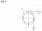
- Patent Document 1 is to prevent the deformation (the roundness change for worse of the outer ring) by increasing a thickness of a cylindrical part of the outer ring in the upper and lower direction. That is, Patent Document 1 discloses a bearing unit using a stationary ring (outer ring) 2 in which a region A3 located in the upper and lower direction is thickened and a region A4 located in a horizontal direction is thinned so as to prevent the mounting deformation upon fastening with the knuckle (refer to FIG. 11 ).
- Patent Document 1 has following problems.
- Patent Document 1 JP-A-2012-148591
- the present invention has been made in view of the above problems, and an object thereof is to provide a bearing unit capable of preventing deformation of a stationary ring-side mounting flange, and preventing deformation of a stationary ring raceway after mounting a vehicle body-side component.
- a first invention of the present invention has a following configuration.
- a bearing unit comprising:
- a second invention of the present invention has a following configuration.
- a third invention of the present invention has a following configuration.
- the bearing unit of the embodiments has substantially the same configuration as the bearing unit shown in FIG. 10 , except for the configuration of the stationary ring (outer ring) 2.
- the descriptions of the same configurations as the bearing unit shown in FIG. 10 are omitted, and only characteristic configurations of the stationary ring (outer ring) 2 are described.
- FIGS. 1A to 3B are schematic views depicting an example of a first embodiment of the stationary ring (outer ring) 2 that is applied to the bearing unit of the present invention.
- the stationary ring (outer ring) 2 is provided integrally with a mounting flange (stationary ring-side flange) 2a.
- the mounting flange 2a includes an annular part 20a protruding radially outward from an outer peripheral surface of the stationary ring 2 by a predetermined radial height, and a plurality of protruding piece portions 20b protruding further radially outward from predetermined positions of an outer peripheral surface of the annular part 20a.
- the four protruding piece portions 20b are arranged at unequal intervals in a circumferential direction.
- Each of the protruding piece portions 20b is formed with a mounting hole 2b for fixing the stationary ring (outer ring) 2 to the vehicle body-side component (knuckle) N.
- a region A1 in which a distance between the mounting holes 2b adjacent in the circumferential direction is larger is set as a first flange part 30, and a region A2 in which a distance between the adjacent mounting holes 2b is smaller is set as a second flange part 40.
- the first flange part 30 is formed to be radially thicker than the second flange part 40 (a radial thickness W1 of the first flange part 30>a radial thickness W2 of the second flange part 40).
- a difference between the radial thickness W1 of the first flange part 30 and the radial thickness W2 of the second flange part 40 is not limited to the shown example, and can be design-changed within the scope of the present invention.
- the radial thickness W1 of the first flange part 30 is constant in the region A1.
- the present invention is not limited thereto, and the radial thickness W1 may not be constant in the region A1.
- the first flange part 30 reaches a rising portion of the protruding piece portion 20b. That is, as compared to the rising portion of the protruding piece portion 20b of the second flange part 40-side, the rising portion of the first flange part 30-side is thicker.
- the radial thickness of the first flange part 30 in which the distance between the mounting holes 2b adjacent in the circumferential direction is large is formed to be thicker than the radial thickness of the second flange part 40 in which the distance between the adjacent mounting holes 2b is small, so that when inserting, fastening and fixing the knuckle bolts Bt into the mounting holes 2b of the stationary ring-side flange 2a, it is possible to prevent the stationary ring-side flange 2a from being warped (deformed), and to prevent deformation of the outer ring raceways S1, S2 after mounting the knuckle.
- the axial surface portion 30a is recessed to form a thickness-reduced portion 50 (refer to FIGS. 1A , 2A and 3A ).
- the axial surface portion 30a may be formed to be axially stepped shape in order to form a thickness-reduced portion 60 (refer to FIGS. 1B , 2B and 3B ).
- the thickness-reduced portion 50 or the thickness-reduced portion 60 is provided, so that a contact area with the bearing mounting surface Nm of the knuckle N is reduced to decrease a contact probability to the concavity and convexity of the bearing mounting surface Nm of the knuckle N. That is, the mounting deformation due to the influence of the concavity and convexity in the mounting surface region is reduced to contribute to the further deformation prevention of the outer ring raceways S1, S2 after mounting the knuckle.
- the thickness-reduced portion 50 or the thickness-reduced portion 60 is not limited to the shown example, and can be design-changed within the scope of the present invention.
- a circumferential length, a radial width, an axial depth and the like of the thickness-reduced portion 50 or the thickness-reduced portion 60 can be design-changed within the scope of the present invention.
- a circumferential length and a radial width of the axial surface portion 30a after forming the thickness-reduced portion 60 are also arbitrary.
- the thickness-reduced portion 50 or the thickness-reduced portion 60 has the continuing groove shape (step shape) but may also be configured by a plurality of groove portions (step portions) divided in the circumferential direction. Also, a circumferential length, a radial width, an axial depth and the like of each divided thickness-reduced portion are arbitrary. In the meantime, it is optional whether the thickness-reduced portion is formed to have a step shape or a concave shape. However, when the thickness-reduced portion is formed to have a step shape, the lifetime of the forging die is prolonged. Also, when the concave shape is formed, like the thickness-reduced portion 50, since the stiffness of the first flange part 30 is improved, it is possible to suppress the roundness break of the double row stationary ring raceways S1, S2.
- FIGS. 4 to 6 are schematic views depicting an example of a second embodiment of the stationary ring (outer ring) 2 that is applied to the bearing unit of the present invention.
- the first flange part 30 located in the region A1 in which the distance between the mounting holes 2b adjacent in the circumferential direction is larger is formed to be axially thicker than the second flange part 40 located in the region A2 in which the distance between the adjacent mounting holes 2b is smaller (an axial thickness W3 of the first flange part 30 >an axial thickness W4 of the second flange part 40).
- a difference between the axial thickness W3 of the first flange part 30 and the axial thickness W4 of the second flange part 40 is not limited to the shown example, and can be design-changed within the scope of the present invention.
- the axial thickness W3 of the first flange part 30 is constant in the region A1. However, the present invention is not limited thereto, and the thickness may not be constant in the region A1.
- the axial thickness W3 (a thickness in the cylinder axis of the cylindrical part of the outer ring) of the first flange part 30 in which the distance between the mounting holes 2b adjacent in the circumferential direction is large is formed to be greater than the axial thickness W4 of the second flange part 40 in which the distance between the adjacent mounting holes 2b is small, so that when inserting, fastening and fixing the knuckle bolts Bt into the mounting holes 2b of the stationary ring-side flange 2a, it is possible to prevent the stationary ring-side flange 2a from being warped (deformed), and to prevent deformation of the outer ring raceways S1, S2 after mounting the knuckle.
- FIGS. 7A to 9B are schematic views depicting an example of a third embodiment of the stationary ring (outer ring) 2 that is applied to the bearing unit of the present invention.
- the radial thickness W1 of the first flange part 30 located in the region A1 in which the distance between the mounting holes 2b adjacent in the circumferential direction is larger is formed to be greater than the radial thickness W2 of the second flange part 40 located in the region A2 in which the distance between the adjacent mounting holes 2b is smaller, and the axial thickness W3 of the first flange part 30 is formed to be greater than the axial thickness W4 of the second flange part 40 (the radial thickness W1 of the first flange part 30>the radial thickness W2 of the second flange part 40, and the axial thickness W3 of the first flange part 30>the axial thickness W4 of the second flange part 40).
- the differences between the radial and axial thicknesses of the first flange part 30 and the second flange part 40 are not limited to the shown example, and can be design-changed within the scope of the present invention.
- the radial thickness W1 and the axial thickness W3 of the first flange part 30 in which the distance between the mounting holes 2b adjacent in the circumferential direction is large are formed to be greater than the radial thickness W2 and the axial thickness W4 of the second flange part 40 in which the distance between the adjacent mounting holes 2b is small, so that when inserting, fastening and fixing the knuckle bolts Bt into the mounting holes 2b of the stationary ring-side flange 2a, it is possible to further prevent the stationary ring-side flange 2a from being warped (deformed), and to prevent deformation of the outer ring raceways S1, S2 after mounting the knuckle.
- the axial surface portion 30a of the first flange part 30 facing the inboard-side cylindrical part P2 is recessed (thickness-reduced) to form the thickness-reduced portion 50 (refer to FIGS. 7A , 8A and 9A ).
- the axial surface portion 30a may be formed to be axially stepped shape in order to to form the thickness-reduced portion 60 (refer to FIGS. 7B , 8B and 9B ).
- the other configurations are the same as the first and second embodiments, the descriptions thereof are omitted.
- the outer diameter surface of the outer ring 2 since the outer diameter surface of the outer ring 2 has the true circle shape, it is easy to provide the outer dimeter surface with a datum surface for grinding.
Landscapes
- Engineering & Computer Science (AREA)
- General Engineering & Computer Science (AREA)
- Mechanical Engineering (AREA)
- Rolling Contact Bearings (AREA)
Abstract
Description
- The present invention relates to, for example, a bearing unit configured to rotatably support a wheel-side component (for example, a disc wheel) of an automobile to a vehicle body-side component (for example, a suspension device (knuckle)), and more particularly, to improvements on a stationary ring configuring a bearing unit and to be mounted to the vehicle body-side component.
- As shown in
FIG. 10 , for example, the bearing unit includes a rotating ring (hub ring) 4, a stationary ring (outer ring) 2, and a plurality ofrolling elements 6, 8. - A mounting flange (rotating ring-side flange) 12a protrudes from an outer peripheral surface of the rotating ring 4. The rotating ring-
side flange 12a is mounted to a wheel-side component (not shown) such as a disc wheel, so that the rotating ring 4 is coupled to be rotatable together with the wheel-side component. - The
stationary ring 2 is disposed to be relatively rotatable to the rotating ring 4 at a radially outward side of the rotating ring 4. A mounting flange (stationary ring-side flange) 2a protrudes from an outer peripheral surface of thestationary ring 2. The stationary ring-side flange 2a is mounted to a vehicle body-side component N such as a knuckle, so that thestationary ring 2 is coupled (kept) to the wheel-side component in a non-rotating state. - The plurality of
rolling elements 6, 8 is incorporated to be rotatable in multiple rows (for example, two rows) between thestationary ring 2 and the rotating ring 4. - A seal member (for example, a vehicle-side combined
seal 10a and a wheel-side lip seal 10b) for sealing an inside of the bearing unit is provided between thestationary ring 2 and the rotating ring 4 in the radial direction. In the meantime, as therolling elements 6, 8, the "balls" are exemplified inFIG. 10 . However, "rollers" may also be applied, depending on a type, a using purpose and the like of the bearing unit. - The stationary ring (outer ring) 2 has a hollow cylindrical shape, and is disposed to cover the outer periphery of the rotating ring (inner ring) 4.
- The stationary ring (outer ring) 2 has an outboard-side cylindrical part P1 having a hollow cylindrical shape and continuing to a wheel-side (outboard-side) of the stationary ring-
side flange 2a, and an inboard-side cylindrical part P2 having a hollow cylindrical shape and continuing to a vehicle-side (inboard-side) of the stationary ring-side flange 2a. The outboard-side cylindrical part P1 continues in a circumferential direction with a predetermined thickness ranging from the stationary ring-side flange 2a to a wheel-side end portion E1. The inboard-side cylindrical part P2 continues in the circumferential direction with a predetermined thickness ranging from the stationary ring-side flange 2a to a vehicle body-side end portion E2. - The stationary ring-
side flange 2a is provided in an unequal distribution in the circumferential direction of the outer peripheral surface of thestationary ring 2. The stationary ring-side flange 2a has fourmounting holes 2b for coupling the same to the vehicle body-side component (knuckle) N via bolts (knuckle bolts) Bt. - The rotating ring (inner ring) 4 is provided with a
hub 12 having a substantially cylindrical shape and configured to support a wheel-side component (for example, a disc wheel) and to rotate together with the wheel-side component. A hub flange (rotating ring-side flange) 12a to which a disc wheel, for example, is fixed protrudes from thehub 12. Thehub flange 12a protrudes radially outward beyond the stationary ring (outer ring) 2. A plurality ofhub bolts 14 arranged at predetermined intervals in the circumferential direction is provided in the vicinity of a protruding tip end edge of thehub flange 12a. The plurality ofhub bolts 14 is inserted into bolt holes (not shown) formed in the disc wheel, and is fastened with hub nuts (not shown), so that it is possible to position and fix the disc wheel to thehub flange 12a. - The rotating ring (inner ring) 4 is fitted at its inboard-side with an annular rotating ring configuring body 16 (a separate inner ring that configures the rotating ring 4 together with the hub 12). In this case, for example, at a state where the plurality of
rolling elements 6, 8 is incorporated between thestationary ring 2 and the rotating ring 4 (specifically, at a state where each of therolling elements 6, 8 is held with a cage 18), the rotatingring configuring body 16 is fitted to astep portion 12b formed at thehub 12. Then, aswaged region 12m of a vehicle body-side end portion of thehub 12 is plastically deformed, so that theswaged region 12m is swaged (closely contacted) along an axial end face 16s of the rotatingring configuring body 16. Thereby, it is possible to fix the rotatingring configuring body 16 to the rotating ring 4 (hub 12). - At this time, the bearing unit is applied with a predetermined preload. At this state, the respective
rolling elements 6, 8 of the multiple rows are rotatably incorporated with predetermined contact angles between thestationary ring 2 and the rotating ring 4 (specifically, between stationary ring raceways S1, S2 of the multiple rows and rotating ring raceways T1, T2 facing the same). At this time, action lines (not shown) connecting two contact points are perpendicular to each of the raceways S1, S2, T1, T2, pass centers of therolling elements 6, 8, and intersect at one point (point of load application) on a central line of the bearing unit. Thereby, a back-to-back arrangement (DB) bearing is configured. - In the above configuration, the force that is applied to wheels during traveling of an automobile is all transmitted from the disc wheel to the knuckle N via the bearing unit. At this time, the bearing unit is applied with diverse loads (radial load, axial load, moment load and the like). However, since the bearing unit is configured as the back-to-back arrangement (DB) bearing as described above, the high stiffness is kept against the diverse loads.
- In the meantime, the bearing unit is coupled with a constant-velocity joint (CVJ). For example, the constant-velocity joint (CVJ) is freely changed in terms of the angle, in conformity to a change in angle of a drive shaft, so that a driving force of predetermined torque is smoothly transmitted to the disc wheel via the bearing unit.
- In the meantime, when fixing the stationary ring (outer ring) 2 to the knuckle N, the four knuckle bolts Bt are respectively inserted and fastened into the
respective mounting holes 2b of the stationary ring-side flange 2a from the vehicle-side (inboard-side) of the knuckle N. At this time, the stationary ring-side flange 2a is warped (deformed), so that a posture of thestationary ring 2 is deformed and a knuckle pilot portion of the inboard-side cylindrical part P2 is contacted to the knuckle N. Thereby, the roundness (a degree of a circular shape deviating from a geometrically exact circle) of the stationary ring raceways S1, S2 of the multiple rows continuously formed in the circumferential direction along the inner periphery of the stationary ring (outer ring) 2 may be changed for worse. - That is, when the knuckle bolt Bt is inserted and fastened in the
mounting hole 2b of the stationary ring-side flange 2a, a fastening force (a fastening force denoted with an arrow D1 inFIG. 10 ) is applied to the outboard-side cylindrical part P1 and the inboard-side cylindrical part P2. At this time, the fastening force applied to the outboard-side cylindrical part P1 partially acts in a direction of pulling the outboard-side cylindrical part P1 toward the stationary ring-side flange 2a (in other words, a direction of stretching the outboard-side cylindrical part P1; a direction denoted with an arrow D2 inFIG. 10 ). Thereby, the roundness of the outboard-side raceway S1 is changed for worse by a stretched degree of the outboard-side cylindrical part P1 toward the stationary ring-side flange part 2a. Then, the outboard-side raceway S1 is deformed into an elliptical shape of which a diameter is lengthened in one direction (an upper and lower direction inFIG. 10 ). - Also, the fastening force applied to the inboard-side cylindrical part P2 partially acts in a direction of shrinking the inboard-side cylindrical part P2 from the stationary ring-
side flange part 2a (in other words, a direction of shrinking the inboard-side cylindrical part P2; a direction denoted with an arrow D3 inFIG. 10 ). Thereby, the roundness of the inboard-side raceway S2 is changed for worse by a shrunken degree of the inboard-side cylindrical part P2 from the stationary ring-side flange part 2a. Then, the inboard-side raceway S2 is deformed into an elliptical shape of which a diameter is lengthened in the other direction (i.e., a horizontal direction perpendicular to the upper and lower direction in which the outboard-side cylindrical part P1 is stretched). - As a first cause of the above deformation, flatness of a
flange surface 2m of the stationary ring-side flange 2a or a bearing mounting surface Nm of the knuckle N is problematic. That is, since the planar surfaces, which are not the geometrically perfect flat surfaces, are closely contacted to each other by the plurality of (for example, three or four) knuckle bolts Bt, the portions adjacent to the respective knuckle bolts Bt can be closely contacted but the portions between the knuckle bolts Bt are deformed in a direction in which a gap is formed. As a result, the stationary ring-side flange part 2a is deformed in a convex shape toward the wheel-side (outboard-side), and the deformation is spread to the outboard-side cylindrical part P1 and the inboard-side cylindrical part P2, so that the roundness of the outboard-side raceway S1 and the inboard-side raceway S2 is changed for worse. - As measures against the above problem, for example, it may be considered to improve the flatness of the
flange surface 2m and the bearing mounting surface Nm. However, the surface processing of intermittently cutting medium or high-carbon steel, which a source material of the stationary ring (outer ring) 2, requires much time and labor, so that the manufacturing cost of the bearing unit increases. - As a second cause of the above deformation, the
flange surface 2m and the bearing mounting surface Nm of the knuckle N are deformed in the vicinity of themounting holes 2b of the stationary ring-side flange 2a due to an influence of an axial force of the knuckle bolt Bt. Also in this deformation, like the first cause, the stationary ring-side flange part 2a is deformed in a convex shape toward the wheel-side (outboard-side), and the deformation is spread to the outboard-side cylindrical part P1 and the inboard-side cylindrical part P2, so that the roundness of the outboard-side raceway S1 and the inboard-side raceway S2 is changed for worse. - As measures against the above problem, a surface hardening treatment may be implemented for any one of the
flange surface 2m and the bearing mounting surface Nm. However, in the case of the stationary ring (outer ring) 2 of which the outboard-side raceway S1 and the inboard-side raceway S2 are subjected to grinding processing after a predetermined heat treatment, it is difficult to implement the surface hardening treatment for theflange surface 2m without influencing each of the raceways S1, S2. - Also, as the other measures, for example, thicknesses of the outboard-side cylindrical part P1 and the inboard-side cylindrical part P2 of the stationary ring (outer ring) 2 may be increased to improve the stiffness thereof. According to this method, it is possible to prevent the roundness of the outboard-side raceway S1 and the inboard-side raceway S2 from being changed for worse. However, when the thicknesses of the outboard-side cylindrical part P1 and the inboard-side cylindrical part P2 are increased, the entire mass of the bearing unit is increased. In this case, an unsprung mass (weight) increases, which is contrary to the improvement of gas mileage and the energy saving and deteriorates the comfortability and drivability. Also, interference occurs when mounting and replacing the hub bolt.
-
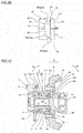
Patent Document 1 is to prevent the deformation (the roundness change for worse of the outer ring) by increasing a thickness of a cylindrical part of the outer ring in the upper and lower direction. That is,Patent Document 1 discloses a bearing unit using a stationary ring (outer ring) 2 in which a region A3 located in the upper and lower direction is thickened and a region A4 located in a horizontal direction is thinned so as to prevent the mounting deformation upon fastening with the knuckle (refer toFIG. 11 ). - However, the structure disclosed in
Patent Document 1 has following problems. - (1) According to the mounting surface stiffness distribution (structurally, the stiffness is different depending on places) of the knuckle structure, it cannot be said that the deformation in the upper and lower direction (vertical direction) is always high, and the deformation of the region in which a distance between the mounting holes of the stationary ring-side flange is large may be increased.
- (2) According to the concavity and convexity distribution (flatness) of the mounting surface of the knuckle-side, it cannot be said that the deformation in the upper and lower direction (vertical direction) is always high, and the deformation of the region in which the distance between the mounting holes is large may be increased.
- (3) The outer ring raceway is ground by an inner surface grinder on the basis of an outer diameter of the outer ring. When an outer diameter surface of the outer ring is made to have a non-circular shape so as to change a thickness, a datum surface cannot be secured, so that it is not possible to perform the grinding. Also, when the circular knuckle pilot portion is set as a datum surface, an axial distance with the raceway is increased, so that it is difficult to obtain the roundness of the raceway.
- Patent Document 1:
JP-A-2012-148591 - The present invention has been made in view of the above problems, and an object thereof is to provide a bearing unit capable of preventing deformation of a stationary ring-side mounting flange, and preventing deformation of a stationary ring raceway after mounting a vehicle body-side component.
- In order to achieve the above object, a first invention of the present invention has a following configuration.
- A bearing unit comprising:
- an annular stationary ring mounted to a vehicle body-side component and to be held in a non-rotating state, and
- a rotating ring provided to face the stationary ring, and configured to rotate together with a wheel-side component with being mounted thereto,
- wherein the stationary ring is provided with a mounting flange along a circumferential direction,
- wherein the mounting flange is provided with a plurality of mounting holes which is arranged at unequal intervals in the circumferential direction and which is used to fasten the stationary ring to the vehicle body-side component via bolts,
- wherein the mounting flange includes a first flange part located in a region in which a distance between the mounting holes adjacent in the circumferential direction is larger, and a second flange part located in a region in which the distance between the adjacent mounting holes is smaller, and
- wherein the first flange part has a radial thickness greater than the second flange part.
- Regarding the first invention, a second invention of the present invention has a following configuration.
- The bearing unit of
Claim 1, wherein a surface of the first flange part facing the vehicle body-side component is provided with a thickness-reduced portion to reduce a contact area with a mounting surface of the vehicle body-side component. - Regarding the first or second invention, a third invention of the present invention has a following configuration.
- The bearing unit of
Claim - According to the present invention, it is possible to prevent deformation of the stationary ring-side mounting flange, and to prevent deformation of a stationary ring raceway after mounting a knuckle.
-
-
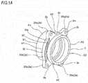
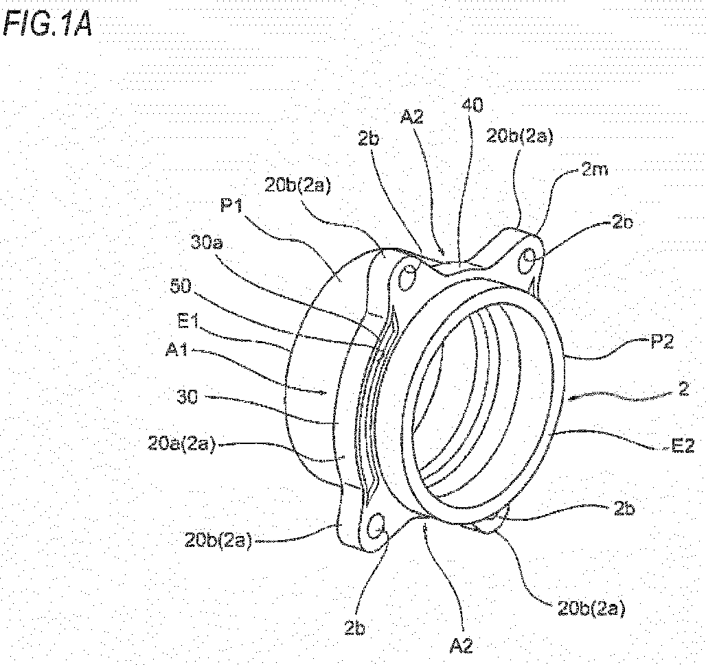
FIG. 1A is a schematic perspective view of a stationary ring of a first embodiment. -
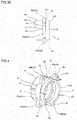
FIG. 1B is a schematic perspective view of another stationary ring of the first embodiment. -
FIG. 2A is a schematic side view of the stationary ring shown inFIG. 1A . -
FIG. 2B is a schematic side view of the stationary ring shown inFIG. 1B . -
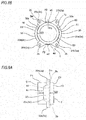
FIG. 3A is a schematic front view of the stationary ring shown inFIG. 1A . -
FIG. 3B is a schematic front view of the stationary ring shown inFIG. 1B . -
FIG. 4 is a schematic perspective view of a stationary ring of a second embodiment. -
FIG. 5 is a schematic side view of the stationary ring shown inFIG. 4 . -
FIG. 6 is a schematic front view of the stationary ring shown inFIG. 4 . -
FIG. 7A is a schematic perspective view of a stationary ring of a third embodiment. -
FIG. 7B is a schematic perspective view of the stationary ring of the third embodiment. -
FIG. 8A is a schematic side view of the stationary ring shown inFIG. 7A . -
FIG. 8B is a schematic side view of the stationary ring shown inFIG. 7B . -
FIG. 9A is a schematic front view of the stationary ring shown inFIG. 7A . -
FIG. 9B is a schematic front view of the stationary ring shown inFIG. 7B . -
FIG. 10 is a schematic longitudinal sectional view depicting an example of the related art. -
FIG. 11 depicts a stationary ring disclosed inPatent Document 1. - Hereinafter, a bearing unit of embodiments of the present invention will be described with reference to the accompanying drawings. The bearing unit of the embodiments has substantially the same configuration as the bearing unit shown in
FIG. 10 , except for the configuration of the stationary ring (outer ring) 2. The descriptions of the same configurations as the bearing unit shown inFIG. 10 are omitted, and only characteristic configurations of the stationary ring (outer ring) 2 are described. -
FIGS. 1A to 3B are schematic views depicting an example of a first embodiment of the stationary ring (outer ring) 2 that is applied to the bearing unit of the present invention. - The stationary ring (outer ring) 2 is provided integrally with a mounting flange (stationary ring-side flange) 2a. The mounting
flange 2a includes anannular part 20a protruding radially outward from an outer peripheral surface of thestationary ring 2 by a predetermined radial height, and a plurality of protrudingpiece portions 20b protruding further radially outward from predetermined positions of an outer peripheral surface of theannular part 20a. - The four
protruding piece portions 20b are arranged at unequal intervals in a circumferential direction. Each of the protrudingpiece portions 20b is formed with a mountinghole 2b for fixing the stationary ring (outer ring) 2 to the vehicle body-side component (knuckle) N. - As shown in
FIGS. 1 and2 , a region A1 in which a distance between the mountingholes 2b adjacent in the circumferential direction is larger is set as afirst flange part 30, and a region A2 in which a distance between the adjacent mountingholes 2b is smaller is set as asecond flange part 40. Thefirst flange part 30 is formed to be radially thicker than the second flange part 40 (a radial thickness W1 of thefirst flange part 30>a radial thickness W2 of the second flange part 40). A difference between the radial thickness W1 of thefirst flange part 30 and the radial thickness W2 of thesecond flange part 40 is not limited to the shown example, and can be design-changed within the scope of the present invention. Also, the radial thickness W1 of thefirst flange part 30 is constant in the region A1. However, the present invention is not limited thereto, and the radial thickness W1 may not be constant in the region A1. Also, in the first embodiment, thefirst flange part 30 reaches a rising portion of the protrudingpiece portion 20b. That is, as compared to the rising portion of the protrudingpiece portion 20b of the second flange part 40-side, the rising portion of the first flange part 30-side is thicker. - In this way, the radial thickness of the
first flange part 30 in which the distance between the mountingholes 2b adjacent in the circumferential direction is large is formed to be thicker than the radial thickness of thesecond flange part 40 in which the distance between the adjacent mountingholes 2b is small, so that when inserting, fastening and fixing the knuckle bolts Bt into the mountingholes 2b of the stationary ring-side flange 2a, it is possible to prevent the stationary ring-side flange 2a from being warped (deformed), and to prevent deformation of the outer ring raceways S1, S2 after mounting the knuckle. - Also, when forming (forging) an
axial surface portion 30a of thefirst flange part 30 facing the inboard-side cylindrical part P2 (knuckle pilot portion), theaxial surface portion 30a is recessed to form a thickness-reduced portion 50 (refer toFIGS. 1A ,2A and3A ). Alternatively, upon the formation (forging), theaxial surface portion 30a may be formed to be axially stepped shape in order to form a thickness-reduced portion 60 (refer toFIGS. 1B ,2B and3B ). In this way, the thickness-reducedportion 50 or the thickness-reducedportion 60 is provided, so that a contact area with the bearing mounting surface Nm of the knuckle N is reduced to decrease a contact probability to the concavity and convexity of the bearing mounting surface Nm of the knuckle N. That is, the mounting deformation due to the influence of the concavity and convexity in the mounting surface region is reduced to contribute to the further deformation prevention of the outer ring raceways S1, S2 after mounting the knuckle. - In the meantime, the thickness-reduced
portion 50 or the thickness-reducedportion 60 is not limited to the shown example, and can be design-changed within the scope of the present invention. For example, a circumferential length, a radial width, an axial depth and the like of the thickness-reducedportion 50 or the thickness-reducedportion 60 can be design-changed within the scope of the present invention. In the meantime, a circumferential length and a radial width of theaxial surface portion 30a after forming the thickness-reducedportion 60 are also arbitrary. Also, in the first embodiment, the thickness-reducedportion 50 or the thickness-reducedportion 60 has the continuing groove shape (step shape) but may also be configured by a plurality of groove portions (step portions) divided in the circumferential direction. Also, a circumferential length, a radial width, an axial depth and the like of each divided thickness-reduced portion are arbitrary. In the meantime, it is optional whether the thickness-reduced portion is formed to have a step shape or a concave shape. However, when the thickness-reduced portion is formed to have a step shape, the lifetime of the forging die is prolonged. Also, when the concave shape is formed, like the thickness-reducedportion 50, since the stiffness of thefirst flange part 30 is improved, it is possible to suppress the roundness break of the double row stationary ring raceways S1, S2. -
FIGS. 4 to 6 are schematic views depicting an example of a second embodiment of the stationary ring (outer ring) 2 that is applied to the bearing unit of the present invention. - As shown in
FIGS. 4 to 6 , in the second embodiment, thefirst flange part 30 located in the region A1 in which the distance between the mountingholes 2b adjacent in the circumferential direction is larger is formed to be axially thicker than thesecond flange part 40 located in the region A2 in which the distance between the adjacent mountingholes 2b is smaller (an axial thickness W3 of thefirst flange part 30 >an axial thickness W4 of the second flange part 40). A difference between the axial thickness W3 of thefirst flange part 30 and the axial thickness W4 of thesecond flange part 40 is not limited to the shown example, and can be design-changed within the scope of the present invention. Also, the axial thickness W3 of thefirst flange part 30 is constant in the region A1. However, the present invention is not limited thereto, and the thickness may not be constant in the region A1. - In this way, the axial thickness W3 (a thickness in the cylinder axis of the cylindrical part of the outer ring) of the
first flange part 30 in which the distance between the mountingholes 2b adjacent in the circumferential direction is large is formed to be greater than the axial thickness W4 of thesecond flange part 40 in which the distance between the adjacent mountingholes 2b is small, so that when inserting, fastening and fixing the knuckle bolts Bt into the mountingholes 2b of the stationary ring-side flange 2a, it is possible to prevent the stationary ring-side flange 2a from being warped (deformed), and to prevent deformation of the outer ring raceways S1, S2 after mounting the knuckle. When an axial dimension of the stationary ring-side flange 2a increases, the stiffness cubically increases with respect to the influence of the concavity and convexity of the bearing mounting surface Nm of the knuckle N. Therefore, the deformation suppression effect of the stationary ring-side flange 2a of the second embodiment further increases, as compared to the first embodiment. In the meantime, since the other configurations are the same as the first embodiment, the descriptions thereof are omitted. -
FIGS. 7A to 9B are schematic views depicting an example of a third embodiment of the stationary ring (outer ring) 2 that is applied to the bearing unit of the present invention. - As shown in
FIGS. 7A to 9B , in the third embodiment, the radial thickness W1 of thefirst flange part 30 located in the region A1 in which the distance between the mountingholes 2b adjacent in the circumferential direction is larger is formed to be greater than the radial thickness W2 of thesecond flange part 40 located in the region A2 in which the distance between the adjacent mountingholes 2b is smaller, and the axial thickness W3 of thefirst flange part 30 is formed to be greater than the axial thickness W4 of the second flange part 40 (the radial thickness W1 of thefirst flange part 30>the radial thickness W2 of thesecond flange part 40, and the axial thickness W3 of thefirst flange part 30>the axial thickness W4 of the second flange part 40). The differences between the radial and axial thicknesses of thefirst flange part 30 and thesecond flange part 40 are not limited to the shown example, and can be design-changed within the scope of the present invention. - In this way, the radial thickness W1 and the axial thickness W3 of the
first flange part 30 in which the distance between the mountingholes 2b adjacent in the circumferential direction is large are formed to be greater than the radial thickness W2 and the axial thickness W4 of thesecond flange part 40 in which the distance between the adjacent mountingholes 2b is small, so that when inserting, fastening and fixing the knuckle bolts Bt into the mountingholes 2b of the stationary ring-side flange 2a, it is possible to further prevent the stationary ring-side flange 2a from being warped (deformed), and to prevent deformation of the outer ring raceways S1, S2 after mounting the knuckle. - Also, in the third embodiment, like the first embodiment, upon the formation (forging), the
axial surface portion 30a of thefirst flange part 30 facing the inboard-side cylindrical part P2 (knuckle pilot portion) is recessed (thickness-reduced) to form the thickness-reduced portion 50 (refer toFIGS. 7A ,8A and9A ). Alternatively, upon the formation (forging), theaxial surface portion 30a may be formed to be axially stepped shape in order to to form the thickness-reduced portion 60 (refer toFIGS. 7B ,8B and9B ). In the meantime, since the other configurations are the same as the first and second embodiments, the descriptions thereof are omitted. - According to each embodiment, since the outer diameter surface of the
outer ring 2 has the true circle shape, it is easy to provide the outer dimeter surface with a datum surface for grinding. - The subject application is based on a Japanese Patent Application No.
2015-144016 filed on July 21, 2015 -
- 2: stationary ring (outer ring)
- 2a: stationary ring-side flange part
- 2b: mounting hole
- 4: rotating ring (inner ring)
- 20b: protruding piece
- 20a: annular part
- 30: first flange part
- 40: second flange part
- N: vehicle body-side component (knuckle)
Claims (3)
- A bearing unit comprising:an annular stationary ring mounted to a vehicle body-side component and to be held in a non-rotating state, anda rotating ring provided to face the stationary ring, and configured to rotate together with a wheel-side component with being mounted thereto,wherein the stationary ring is provided with a mounting flange along a circumferential direction,wherein the mounting flange is provided with a plurality of mounting holes which is arranged at unequal intervals in the circumferential direction and which is used to fasten the stationary ring to the vehicle body-side component via bolts,wherein the mounting flange includes a first flange part located in a region in which a distance between the mounting holes adjacent in the circumferential direction is larger, and a second flange part located in a region in which the distance between the adjacent mounting holes is smaller, andwherein a radial thickness of the first flange part is greater than a radial thickness of the second flange part.
- The bearing unit according to Claim I, wherein a surface of the first flange part facing the vehicle body-side component is provided with a thickness-reduced portion to reduce a contact area with a mounting surface of the vehicle body-side component.
- The bearing unit according to Claim 1 or 2, wherein an axial thickness of the first flange part is greater than an axial thickness of the second flange part.
Applications Claiming Priority (2)
| Application Number | Priority Date | Filing Date | Title |
|---|---|---|---|
| JP2015144016A JP2017025998A (en) | 2015-07-21 | 2015-07-21 | Bearing unit |
| PCT/JP2016/062934 WO2017013917A1 (en) | 2015-07-21 | 2016-04-25 | Bearing unit |
Publications (3)
| Publication Number | Publication Date |
|---|---|
| EP3327300A1 true EP3327300A1 (en) | 2018-05-30 |
| EP3327300A4 EP3327300A4 (en) | 2018-05-30 |
| EP3327300B1 EP3327300B1 (en) | 2019-12-11 |
Family
ID=57835184
Family Applications (1)
| Application Number | Title | Priority Date | Filing Date |
|---|---|---|---|
| EP16827481.9A Active EP3327300B1 (en) | 2015-07-21 | 2016-04-25 | Bearing unit |
Country Status (5)
| Country | Link |
|---|---|
| US (1) | US10520028B2 (en) |
| EP (1) | EP3327300B1 (en) |
| JP (1) | JP2017025998A (en) |
| CN (1) | CN107923441A (en) |
| WO (1) | WO2017013917A1 (en) |
Families Citing this family (4)
| Publication number | Priority date | Publication date | Assignee | Title |
|---|---|---|---|---|
| CN108688405A (en) * | 2018-07-25 | 2018-10-23 | 上汽通用五菱汽车股份有限公司 | A kind of automobile drive axle wheel hub end structure |
| DE102019108836B4 (en) * | 2019-04-04 | 2021-07-01 | Hirschvogel Umformtechnik Gmbh | Arrangement of a bearing component on a chassis component, bearing component and chassis component for such an arrangement and a method for their production |
| JP7306287B2 (en) * | 2020-02-05 | 2023-07-11 | 日本精工株式会社 | hub unit bearing |
| DE102024131143A1 (en) * | 2024-07-08 | 2026-01-08 | Schaeffler Technologies AG & Co. KG | Wheel bearings with raceway for improved stiffness at zero crossing |
Family Cites Families (10)
| Publication number | Priority date | Publication date | Assignee | Title |
|---|---|---|---|---|
| JP4203909B2 (en) * | 2003-08-25 | 2009-01-07 | 株式会社デンソー | Vane pump |
| JP2005170344A (en) * | 2003-12-15 | 2005-06-30 | Nsk Ltd | Wheel hub and wheel hub unit |
| JP2007071352A (en) * | 2005-09-09 | 2007-03-22 | Jtekt Corp | Rolling bearing device for wheels |
| JP4345988B2 (en) * | 2007-04-16 | 2009-10-14 | Ntn株式会社 | Wheel bearing device |
| JP2012082870A (en) * | 2010-10-07 | 2012-04-26 | Jtekt Corp | Outer ring of rolling bearing device for wheel |
| JP5616758B2 (en) * | 2010-11-16 | 2014-10-29 | Ntn株式会社 | Wheel bearing device with rotation speed detector |
| JP2012148591A (en) | 2011-01-17 | 2012-08-09 | Jtekt Corp | Rolling bearing device for wheel |
| WO2013047346A1 (en) * | 2011-09-29 | 2013-04-04 | Ntn株式会社 | Wheel bearing apparatus with sensor |
| JP6224402B2 (en) * | 2013-10-04 | 2017-11-01 | Ntn株式会社 | Method for manufacturing outer member of wheel bearing device |
| JP2015105670A (en) * | 2013-11-28 | 2015-06-08 | 株式会社ジェイテクト | Rolling bearing, and power transmission device equipped with the same |
-
2015
- 2015-07-21 JP JP2015144016A patent/JP2017025998A/en active Pending
-
2016
- 2016-04-25 CN CN201680043011.5A patent/CN107923441A/en active Pending
- 2016-04-25 US US15/739,247 patent/US10520028B2/en active Active
- 2016-04-25 WO PCT/JP2016/062934 patent/WO2017013917A1/en not_active Ceased
- 2016-04-25 EP EP16827481.9A patent/EP3327300B1/en active Active
Also Published As
| Publication number | Publication date |
|---|---|
| CN107923441A (en) | 2018-04-17 |
| WO2017013917A1 (en) | 2017-01-26 |
| US20190023073A1 (en) | 2019-01-24 |
| JP2017025998A (en) | 2017-02-02 |
| EP3327300B1 (en) | 2019-12-11 |
| EP3327300A4 (en) | 2018-05-30 |
| US10520028B2 (en) | 2019-12-31 |
Similar Documents
| Publication | Publication Date | Title |
|---|---|---|
| EP3327300B1 (en) | Bearing unit | |
| JP2004340242A (en) | Tapered roller bearing device for wheel | |
| JP2013147052A (en) | Wheel rolling bearing device | |
| CN102602245B (en) | Bearing unit for wheel | |
| US20150191044A1 (en) | Bearing module | |
| EP2889498B1 (en) | Wheel Bearing Device | |
| JP2009058077A (en) | Wheel bearing unit | |
| JP5644665B2 (en) | Bearing unit | |
| US8770852B2 (en) | Wheel bearing device | |
| JP6515774B2 (en) | Double row tapered roller bearing unit for wheel support | |
| JP2016109293A (en) | Rolling bearing unit for wheel support | |
| JP2012228909A (en) | Hub unit for supporting wheel | |
| JP4779953B2 (en) | Bearing unit manufacturing method and bearing unit | |
| US20130062929A1 (en) | Hub unit | |
| JP2022071682A (en) | Wheel bearings and wheel bearing devices | |
| JP2016044784A (en) | Bearing device for supporting wheel | |
| JP4899921B2 (en) | Bearing assembly method | |
| JP2007016959A (en) | Manufacturing method of outer ring of rolling bearing unit for wheel support | |
| JP7619117B2 (en) | Wheel drive unit and assembly method thereof | |
| JP2014088923A (en) | Wheel supporting bearing unit | |
| CN205768351U (en) | Hub unit bearing | |
| WO2017033653A1 (en) | Rolling bearing unit for wheel support | |
| JP2023074355A (en) | Rolling bearing unit for wheel support | |
| JP2023043696A (en) | Wheel bearing device | |
| JP2011133067A (en) | Bearing device for wheel |
Legal Events
| Date | Code | Title | Description |
|---|---|---|---|
| STAA | Information on the status of an ep patent application or granted ep patent |
Free format text: STATUS: THE INTERNATIONAL PUBLICATION HAS BEEN MADE |
|
| PUAI | Public reference made under article 153(3) epc to a published international application that has entered the european phase |
Free format text: ORIGINAL CODE: 0009012 |
|
| STAA | Information on the status of an ep patent application or granted ep patent |
Free format text: STATUS: REQUEST FOR EXAMINATION WAS MADE |
|
| 17P | Request for examination filed |
Effective date: 20180117 |
|
| A4 | Supplementary search report drawn up and despatched |
Effective date: 20180504 |
|
| AK | Designated contracting states |
Kind code of ref document: A1 Designated state(s): AL AT BE BG CH CY CZ DE DK EE ES FI FR GB GR HR HU IE IS IT LI LT LU LV MC MK MT NL NO PL PT RO RS SE SI SK SM TR |
|
| AX | Request for extension of the european patent |
Extension state: BA ME |
|
| DAV | Request for validation of the european patent (deleted) | ||
| DAX | Request for extension of the european patent (deleted) | ||
| GRAP | Despatch of communication of intention to grant a patent |
Free format text: ORIGINAL CODE: EPIDOSNIGR1 |
|
| STAA | Information on the status of an ep patent application or granted ep patent |
Free format text: STATUS: GRANT OF PATENT IS INTENDED |
|
| INTG | Intention to grant announced |
Effective date: 20190705 |
|
| RIN1 | Information on inventor provided before grant (corrected) |
Inventor name: SAKODA, HIRONARI |
|
| GRAJ | Information related to disapproval of communication of intention to grant by the applicant or resumption of examination proceedings by the epo deleted |
Free format text: ORIGINAL CODE: EPIDOSDIGR1 |
|
| STAA | Information on the status of an ep patent application or granted ep patent |
Free format text: STATUS: REQUEST FOR EXAMINATION WAS MADE |
|
| GRAP | Despatch of communication of intention to grant a patent |
Free format text: ORIGINAL CODE: EPIDOSNIGR1 |
|
| STAA | Information on the status of an ep patent application or granted ep patent |
Free format text: STATUS: GRANT OF PATENT IS INTENDED |
|
| INTC | Intention to grant announced (deleted) | ||
| INTG | Intention to grant announced |
Effective date: 20190912 |
|
| GRAS | Grant fee paid |
Free format text: ORIGINAL CODE: EPIDOSNIGR3 |
|
| GRAA | (expected) grant |
Free format text: ORIGINAL CODE: 0009210 |
|
| STAA | Information on the status of an ep patent application or granted ep patent |
Free format text: STATUS: THE PATENT HAS BEEN GRANTED |
|
| AK | Designated contracting states |
Kind code of ref document: B1 Designated state(s): AL AT BE BG CH CY CZ DE DK EE ES FI FR GB GR HR HU IE IS IT LI LT LU LV MC MK MT NL NO PL PT RO RS SE SI SK SM TR |
|
| REG | Reference to a national code |
Ref country code: GB Ref legal event code: FG4D |
|
| REG | Reference to a national code |
Ref country code: CH Ref legal event code: EP |
|
| REG | Reference to a national code |
Ref country code: AT Ref legal event code: REF Ref document number: 1212484 Country of ref document: AT Kind code of ref document: T Effective date: 20191215 |
|
| REG | Reference to a national code |
Ref country code: DE Ref legal event code: R096 Ref document number: 602016026166 Country of ref document: DE |
|
| REG | Reference to a national code |
Ref country code: IE Ref legal event code: FG4D |
|
| REG | Reference to a national code |
Ref country code: NL Ref legal event code: MP Effective date: 20191211 |
|
| REG | Reference to a national code |
Ref country code: LT Ref legal event code: MG4D |
|
| PG25 | Lapsed in a contracting state [announced via postgrant information from national office to epo] |
Ref country code: BG Free format text: LAPSE BECAUSE OF FAILURE TO SUBMIT A TRANSLATION OF THE DESCRIPTION OR TO PAY THE FEE WITHIN THE PRESCRIBED TIME-LIMIT Effective date: 20200311 Ref country code: FI Free format text: LAPSE BECAUSE OF FAILURE TO SUBMIT A TRANSLATION OF THE DESCRIPTION OR TO PAY THE FEE WITHIN THE PRESCRIBED TIME-LIMIT Effective date: 20191211 Ref country code: SE Free format text: LAPSE BECAUSE OF FAILURE TO SUBMIT A TRANSLATION OF THE DESCRIPTION OR TO PAY THE FEE WITHIN THE PRESCRIBED TIME-LIMIT Effective date: 20191211 Ref country code: NO Free format text: LAPSE BECAUSE OF FAILURE TO SUBMIT A TRANSLATION OF THE DESCRIPTION OR TO PAY THE FEE WITHIN THE PRESCRIBED TIME-LIMIT Effective date: 20200311 Ref country code: LV Free format text: LAPSE BECAUSE OF FAILURE TO SUBMIT A TRANSLATION OF THE DESCRIPTION OR TO PAY THE FEE WITHIN THE PRESCRIBED TIME-LIMIT Effective date: 20191211 Ref country code: GR Free format text: LAPSE BECAUSE OF FAILURE TO SUBMIT A TRANSLATION OF THE DESCRIPTION OR TO PAY THE FEE WITHIN THE PRESCRIBED TIME-LIMIT Effective date: 20200312 Ref country code: LT Free format text: LAPSE BECAUSE OF FAILURE TO SUBMIT A TRANSLATION OF THE DESCRIPTION OR TO PAY THE FEE WITHIN THE PRESCRIBED TIME-LIMIT Effective date: 20191211 |
|
| PG25 | Lapsed in a contracting state [announced via postgrant information from national office to epo] |
Ref country code: HR Free format text: LAPSE BECAUSE OF FAILURE TO SUBMIT A TRANSLATION OF THE DESCRIPTION OR TO PAY THE FEE WITHIN THE PRESCRIBED TIME-LIMIT Effective date: 20191211 Ref country code: RS Free format text: LAPSE BECAUSE OF FAILURE TO SUBMIT A TRANSLATION OF THE DESCRIPTION OR TO PAY THE FEE WITHIN THE PRESCRIBED TIME-LIMIT Effective date: 20191211 |
|
| PG25 | Lapsed in a contracting state [announced via postgrant information from national office to epo] |
Ref country code: AL Free format text: LAPSE BECAUSE OF FAILURE TO SUBMIT A TRANSLATION OF THE DESCRIPTION OR TO PAY THE FEE WITHIN THE PRESCRIBED TIME-LIMIT Effective date: 20191211 |
|
| PG25 | Lapsed in a contracting state [announced via postgrant information from national office to epo] |
Ref country code: EE Free format text: LAPSE BECAUSE OF FAILURE TO SUBMIT A TRANSLATION OF THE DESCRIPTION OR TO PAY THE FEE WITHIN THE PRESCRIBED TIME-LIMIT Effective date: 20191211 Ref country code: PT Free format text: LAPSE BECAUSE OF FAILURE TO SUBMIT A TRANSLATION OF THE DESCRIPTION OR TO PAY THE FEE WITHIN THE PRESCRIBED TIME-LIMIT Effective date: 20200506 Ref country code: ES Free format text: LAPSE BECAUSE OF FAILURE TO SUBMIT A TRANSLATION OF THE DESCRIPTION OR TO PAY THE FEE WITHIN THE PRESCRIBED TIME-LIMIT Effective date: 20191211 Ref country code: NL Free format text: LAPSE BECAUSE OF FAILURE TO SUBMIT A TRANSLATION OF THE DESCRIPTION OR TO PAY THE FEE WITHIN THE PRESCRIBED TIME-LIMIT Effective date: 20191211 Ref country code: CZ Free format text: LAPSE BECAUSE OF FAILURE TO SUBMIT A TRANSLATION OF THE DESCRIPTION OR TO PAY THE FEE WITHIN THE PRESCRIBED TIME-LIMIT Effective date: 20191211 Ref country code: RO Free format text: LAPSE BECAUSE OF FAILURE TO SUBMIT A TRANSLATION OF THE DESCRIPTION OR TO PAY THE FEE WITHIN THE PRESCRIBED TIME-LIMIT Effective date: 20191211 |
|
| PGFP | Annual fee paid to national office [announced via postgrant information from national office to epo] |
Ref country code: DE Payment date: 20200415 Year of fee payment: 5 |
|
| PG25 | Lapsed in a contracting state [announced via postgrant information from national office to epo] |
Ref country code: SM Free format text: LAPSE BECAUSE OF FAILURE TO SUBMIT A TRANSLATION OF THE DESCRIPTION OR TO PAY THE FEE WITHIN THE PRESCRIBED TIME-LIMIT Effective date: 20191211 Ref country code: IS Free format text: LAPSE BECAUSE OF FAILURE TO SUBMIT A TRANSLATION OF THE DESCRIPTION OR TO PAY THE FEE WITHIN THE PRESCRIBED TIME-LIMIT Effective date: 20200411 Ref country code: SK Free format text: LAPSE BECAUSE OF FAILURE TO SUBMIT A TRANSLATION OF THE DESCRIPTION OR TO PAY THE FEE WITHIN THE PRESCRIBED TIME-LIMIT Effective date: 20191211 |
|
| REG | Reference to a national code |
Ref country code: DE Ref legal event code: R097 Ref document number: 602016026166 Country of ref document: DE |
|
| REG | Reference to a national code |
Ref country code: AT Ref legal event code: MK05 Ref document number: 1212484 Country of ref document: AT Kind code of ref document: T Effective date: 20191211 |
|
| PLBE | No opposition filed within time limit |
Free format text: ORIGINAL CODE: 0009261 |
|
| STAA | Information on the status of an ep patent application or granted ep patent |
Free format text: STATUS: NO OPPOSITION FILED WITHIN TIME LIMIT |
|
| PG25 | Lapsed in a contracting state [announced via postgrant information from national office to epo] |
Ref country code: DK Free format text: LAPSE BECAUSE OF FAILURE TO SUBMIT A TRANSLATION OF THE DESCRIPTION OR TO PAY THE FEE WITHIN THE PRESCRIBED TIME-LIMIT Effective date: 20191211 |
|
| 26N | No opposition filed |
Effective date: 20200914 |
|
| PG25 | Lapsed in a contracting state [announced via postgrant information from national office to epo] |
Ref country code: AT Free format text: LAPSE BECAUSE OF FAILURE TO SUBMIT A TRANSLATION OF THE DESCRIPTION OR TO PAY THE FEE WITHIN THE PRESCRIBED TIME-LIMIT Effective date: 20191211 Ref country code: MC Free format text: LAPSE BECAUSE OF FAILURE TO SUBMIT A TRANSLATION OF THE DESCRIPTION OR TO PAY THE FEE WITHIN THE PRESCRIBED TIME-LIMIT Effective date: 20191211 Ref country code: SI Free format text: LAPSE BECAUSE OF FAILURE TO SUBMIT A TRANSLATION OF THE DESCRIPTION OR TO PAY THE FEE WITHIN THE PRESCRIBED TIME-LIMIT Effective date: 20191211 |
|
| REG | Reference to a national code |
Ref country code: CH Ref legal event code: PL |
|
| PG25 | Lapsed in a contracting state [announced via postgrant information from national office to epo] |
Ref country code: LU Free format text: LAPSE BECAUSE OF NON-PAYMENT OF DUE FEES Effective date: 20200425 Ref country code: CH Free format text: LAPSE BECAUSE OF NON-PAYMENT OF DUE FEES Effective date: 20200430 Ref country code: LI Free format text: LAPSE BECAUSE OF NON-PAYMENT OF DUE FEES Effective date: 20200430 Ref country code: FR Free format text: LAPSE BECAUSE OF NON-PAYMENT OF DUE FEES Effective date: 20200430 Ref country code: IT Free format text: LAPSE BECAUSE OF FAILURE TO SUBMIT A TRANSLATION OF THE DESCRIPTION OR TO PAY THE FEE WITHIN THE PRESCRIBED TIME-LIMIT Effective date: 20191211 |
|
| REG | Reference to a national code |
Ref country code: BE Ref legal event code: MM Effective date: 20200430 |
|
| PG25 | Lapsed in a contracting state [announced via postgrant information from national office to epo] |
Ref country code: PL Free format text: LAPSE BECAUSE OF FAILURE TO SUBMIT A TRANSLATION OF THE DESCRIPTION OR TO PAY THE FEE WITHIN THE PRESCRIBED TIME-LIMIT Effective date: 20191211 Ref country code: BE Free format text: LAPSE BECAUSE OF NON-PAYMENT OF DUE FEES Effective date: 20200430 |
|
| GBPC | Gb: european patent ceased through non-payment of renewal fee |
Effective date: 20200425 |
|
| PG25 | Lapsed in a contracting state [announced via postgrant information from national office to epo] |
Ref country code: IE Free format text: LAPSE BECAUSE OF NON-PAYMENT OF DUE FEES Effective date: 20200425 Ref country code: GB Free format text: LAPSE BECAUSE OF NON-PAYMENT OF DUE FEES Effective date: 20200425 |
|
| REG | Reference to a national code |
Ref country code: DE Ref legal event code: R119 Ref document number: 602016026166 Country of ref document: DE |
|
| PG25 | Lapsed in a contracting state [announced via postgrant information from national office to epo] |
Ref country code: DE Free format text: LAPSE BECAUSE OF NON-PAYMENT OF DUE FEES Effective date: 20211103 |
|
| PG25 | Lapsed in a contracting state [announced via postgrant information from national office to epo] |
Ref country code: TR Free format text: LAPSE BECAUSE OF FAILURE TO SUBMIT A TRANSLATION OF THE DESCRIPTION OR TO PAY THE FEE WITHIN THE PRESCRIBED TIME-LIMIT Effective date: 20191211 Ref country code: MT Free format text: LAPSE BECAUSE OF FAILURE TO SUBMIT A TRANSLATION OF THE DESCRIPTION OR TO PAY THE FEE WITHIN THE PRESCRIBED TIME-LIMIT Effective date: 20191211 Ref country code: CY Free format text: LAPSE BECAUSE OF FAILURE TO SUBMIT A TRANSLATION OF THE DESCRIPTION OR TO PAY THE FEE WITHIN THE PRESCRIBED TIME-LIMIT Effective date: 20191211 |
|
| PG25 | Lapsed in a contracting state [announced via postgrant information from national office to epo] |
Ref country code: MK Free format text: LAPSE BECAUSE OF FAILURE TO SUBMIT A TRANSLATION OF THE DESCRIPTION OR TO PAY THE FEE WITHIN THE PRESCRIBED TIME-LIMIT Effective date: 20191211 |