EP3327284A1 - Connection assembly for wind turbine tower - Google Patents
Connection assembly for wind turbine tower Download PDFInfo
- Publication number
- EP3327284A1 EP3327284A1 EP17203379.7A EP17203379A EP3327284A1 EP 3327284 A1 EP3327284 A1 EP 3327284A1 EP 17203379 A EP17203379 A EP 17203379A EP 3327284 A1 EP3327284 A1 EP 3327284A1
- Authority
- EP
- European Patent Office
- Prior art keywords
- connector plate
- tower section
- plate portion
- section segment
- tower
- Prior art date
- Legal status (The legal status is an assumption and is not a legal conclusion. Google has not performed a legal analysis and makes no representation as to the accuracy of the status listed.)
- Granted
Links
Images




Classifications
-
- E—FIXED CONSTRUCTIONS
- E04—BUILDING
- E04H—BUILDINGS OR LIKE STRUCTURES FOR PARTICULAR PURPOSES; SWIMMING OR SPLASH BATHS OR POOLS; MASTS; FENCING; TENTS OR CANOPIES, IN GENERAL
- E04H12/00—Towers; Masts or poles; Chimney stacks; Water-towers; Methods of erecting such structures
- E04H12/02—Structures made of specified materials
- E04H12/08—Structures made of specified materials of metal
-
- F—MECHANICAL ENGINEERING; LIGHTING; HEATING; WEAPONS; BLASTING
- F03—MACHINES OR ENGINES FOR LIQUIDS; WIND, SPRING, OR WEIGHT MOTORS; PRODUCING MECHANICAL POWER OR A REACTIVE PROPULSIVE THRUST, NOT OTHERWISE PROVIDED FOR
- F03D—WIND MOTORS
- F03D13/00—Assembly, mounting or commissioning of wind motors; Arrangements specially adapted for transporting wind motor components
- F03D13/20—Arrangements for mounting or supporting wind motors; Masts or towers for wind motors
-
- E—FIXED CONSTRUCTIONS
- E04—BUILDING
- E04B—GENERAL BUILDING CONSTRUCTIONS; WALLS, e.g. PARTITIONS; ROOFS; FLOORS; CEILINGS; INSULATION OR OTHER PROTECTION OF BUILDINGS
- E04B1/00—Constructions in general; Structures which are not restricted either to walls, e.g. partitions, or floors or ceilings or roofs
- E04B1/38—Connections for building structures in general
- E04B1/48—Dowels, i.e. members adapted to penetrate the surfaces of two parts and to take the shear stresses
-
- F—MECHANICAL ENGINEERING; LIGHTING; HEATING; WEAPONS; BLASTING
- F16—ENGINEERING ELEMENTS AND UNITS; GENERAL MEASURES FOR PRODUCING AND MAINTAINING EFFECTIVE FUNCTIONING OF MACHINES OR INSTALLATIONS; THERMAL INSULATION IN GENERAL
- F16B—DEVICES FOR FASTENING OR SECURING CONSTRUCTIONAL ELEMENTS OR MACHINE PARTS TOGETHER, e.g. NAILS, BOLTS, CIRCLIPS, CLAMPS, CLIPS OR WEDGES; JOINTS OR JOINTING
- F16B5/00—Joining sheets or plates, e.g. panels, to one another or to strips or bars parallel to them
- F16B5/04—Joining sheets or plates, e.g. panels, to one another or to strips or bars parallel to them by means of riveting
- F16B5/045—Joining sheets or plates, e.g. panels, to one another or to strips or bars parallel to them by means of riveting without the use of separate rivets
-
- F—MECHANICAL ENGINEERING; LIGHTING; HEATING; WEAPONS; BLASTING
- F16—ENGINEERING ELEMENTS AND UNITS; GENERAL MEASURES FOR PRODUCING AND MAINTAINING EFFECTIVE FUNCTIONING OF MACHINES OR INSTALLATIONS; THERMAL INSULATION IN GENERAL
- F16B—DEVICES FOR FASTENING OR SECURING CONSTRUCTIONAL ELEMENTS OR MACHINE PARTS TOGETHER, e.g. NAILS, BOLTS, CIRCLIPS, CLAMPS, CLIPS OR WEDGES; JOINTS OR JOINTING
- F16B5/00—Joining sheets or plates, e.g. panels, to one another or to strips or bars parallel to them
- F16B5/12—Fastening strips or bars to sheets or plates, e.g. rubber strips, decorative strips for motor vehicles, by means of clips
-
- E—FIXED CONSTRUCTIONS
- E04—BUILDING
- E04B—GENERAL BUILDING CONSTRUCTIONS; WALLS, e.g. PARTITIONS; ROOFS; FLOORS; CEILINGS; INSULATION OR OTHER PROTECTION OF BUILDINGS
- E04B1/00—Constructions in general; Structures which are not restricted either to walls, e.g. partitions, or floors or ceilings or roofs
- E04B1/18—Structures comprising elongated load-supporting parts, e.g. columns, girders, skeletons
- E04B1/24—Structures comprising elongated load-supporting parts, e.g. columns, girders, skeletons the supporting parts consisting of metal
- E04B1/2403—Connection details of the elongated load-supporting parts
- E04B2001/2415—Brackets, gussets, joining plates
-
- Y—GENERAL TAGGING OF NEW TECHNOLOGICAL DEVELOPMENTS; GENERAL TAGGING OF CROSS-SECTIONAL TECHNOLOGIES SPANNING OVER SEVERAL SECTIONS OF THE IPC; TECHNICAL SUBJECTS COVERED BY FORMER USPC CROSS-REFERENCE ART COLLECTIONS [XRACs] AND DIGESTS
- Y02—TECHNOLOGIES OR APPLICATIONS FOR MITIGATION OR ADAPTATION AGAINST CLIMATE CHANGE
- Y02E—REDUCTION OF GREENHOUSE GAS [GHG] EMISSIONS, RELATED TO ENERGY GENERATION, TRANSMISSION OR DISTRIBUTION
- Y02E10/00—Energy generation through renewable energy sources
- Y02E10/70—Wind energy
- Y02E10/728—Onshore wind turbines
Definitions
- the present disclosure generally relates to wind turbines. More particularly, the present disclosure relates to connection assemblies for towers of wind turbines.
- Wind power is considered one of the cleanest, most environmentally friendly energy sources presently available, and wind turbines have gained increased attention in this regard.
- a modern wind turbine typically includes a tower, a nacelle mounted on the tower, a generator positioned in the nacelle, and one or more rotor blades.
- the one or more rotor blades convert the kinetic energy of wind into mechanical energy using known airfoil principles.
- a shaft transmits the mechanical energy from the rotor blades to the generator.
- the generator then converts the mechanical energy to electrical energy that may be supplied to a utility grid.
- the tower may be constructed from a plurality of tower sections.
- each of the tower sections may be stacked, e.g., vertically, and coupled together to form the tower.
- Each of the tower sections may, in turn, be formed from a plurality of tower section segments.
- the tower section segments may be annularly arranged and coupled together to form the tower section.
- connection assemblies may include a flange welded to each tower section segment being coupled. A spacer may then be positioned between the flanges before coupling the flanges with bolts. Furthermore, it may be necessary to place a filler material in the joint between the adjacent tower section segments. In this respect, the assembly of the tower section using conventional connection assemblies may be time-consuming, thereby increasing the cost of the wind turbine.
- connection assemblies for wind turbine towers.
- connection assemblies that do not require the use of spacers and/or filler materials and that are relatively more efficient to use would be advantageous.
- connection assembly for a tower of a wind turbine.
- the connection assembly includes a first tower section segment having an inner surface spaced apart from an outer surface.
- a second tower section segment is positioned adjacent to the first tower section segment and includes an inner surface spaced apart from an outer surface.
- the first tower section segment and the second tower section segment define a vertically extending gap therebetween.
- a connector plate includes a first connector plate portion, a second connector plate portion spaced apart from the first connector plate portion, and a third connector plate portion positioned between the first connector plate portion and the second connector plate portion.
- the first connector plate portion couples to the first tower section segment.
- the second connector plate portion couples to the second tower section segment.
- the third connector plate portion extends through the vertically extending gap.
- the present disclosure is directed to a wind turbine having a nacelle and a rotor coupled to the nacelle.
- the rotor includes a hub and at least one rotor blade extending from the hub.
- a tower supports the nacelle and includes a first tower section segment having an inner surface spaced apart from an outer surface.
- a second tower section segment is positioned adjacent to the first tower section segment.
- the second tower section segment includes an inner surface spaced apart from an outer surface.
- the first tower section segment and the second tower section segment define a vertically extending gap therebetween.
- a connector plate includes a first connector plate portion, a second connector plate portion spaced apart from the first connector plate portion, and a third connector plate portion positioned between the first connector plate portion and the second connector plate portion.
- the first connector plate portion couples to the first tower section segment.
- the second connector plate portion couples to the second tower section segment.
- the third connector plate portion extends through the vertically extending gap.
- FIG. 1 illustrates a perspective view of one embodiment of an exemplary wind turbine 10 in accordance with the present disclosure.
- the wind turbine 10 generally includes a tower 12 extending from a support surface 14, a nacelle 16 mounted on the tower 12, and a rotor 18 coupled to the nacelle 16.
- the rotor 18 includes a rotatable hub 20 and at least one rotor blade 22 coupled to and extending outwardly from the hub 20.
- the rotor 18 includes three rotor blades 22. In alternative embodiments, however, the rotor 18 may include more or less than three rotor blades 22.
- Each rotor blade 22 may be spaced about the hub 20 to facilitate rotating the rotor 18 to convert kinetic energy from the wind into usable mechanical energy, and subsequently, electrical energy.
- the hub 20 may be rotatably coupled to an electric generator 24 positioned within the nacelle 16.
- the tower 12 may include a plurality of tower sections 26.
- the tower sections 26 are stacked (e.g., vertically) and coupled together so that the tower 12 positions the nacelle 16 a desired distance away from the support surface 14.
- the tower 12 includes five tower sections 26. Alternate embodiments of the tower 12, however, may include more or less than five tower sections 26.
- FIGS. 2 and 3 illustrate one of the tower sections 26 shown in FIG. 1 in greater detail.
- FIG. 2 is a front view of one of the tower sections 26, and
- FIG. 3 is a top view of one of the tower sections 26.
- the tower section 26 defines an axial centerline 28 that extends therethrough.
- the tower section 26 defines an axial direction A, a radial direction R, and a circumferential direction C.
- the axial direction A extends parallel to the axial centerline 28
- the radial direction R extends orthogonally outward from the axial centerline 28
- the circumferential direction C extends concentrically around the axial centerline 28.
- the tower section 26 may be formed from a plurality of tower section segments.
- the tower section 26 includes a first tower section segment 30, a second tower section segment 32, and a third tower section segment 34.
- the first, second, and third tower section segments 30, 32, 34 are arranged in a generally annular array about the axial centerline 28 and are radially spaced apart from the axial centerline 28.
- the tower section 26 defines an interior space 36 through which, e.g., wiring (not shown) coupling the electric generator 24 to a power grid (not shown) may extend and in which wind turbine equipment and platforms may be positioned.
- the tower section 26 may have more or less than three tower section segments.
- Each tower section segment includes inner and outer surfaces.
- the first tower section segment 30 includes an inner surface 38 radially spaced apart from an outer surface 40.
- the second tower section segment 32 similarly includes an inner surface 42 radially spaced apart from an outer surface 44.
- the third tower section segment 34 similarly includes an inner surface 45 radially spaced apart from an outer surface 46.
- the outer surfaces 40, 44, 46 of the first, second, and third tower section segments 30, 32, 34 are radially aligned with each other.
- the inner surfaces 38, 42, 45 of the first, second, and third tower section segments 30, 32, 34 are radially aligned with each other.
- the inner surfaces 38, 42, 45 demarcate the radially outer boundary of the interior space 36 defined by the tower section 26.
- the edges of the tower section segments may rectangular as shown in FIG. 3 or rounded as shown in FIG. 4 .
- the first, second, and third tower section segments 30, 32, 34 may extend for the entire length of the tower section 26 in the axial direction A. As shown in FIG. 2 , the first tower section segment 30 defines an axial length 48. Similarly, the second tower section segment 32 defines an axial length 50. Although not shown, the third tower section segment 34 also defines an axial length. In an exemplary embodiment, the axial lengths 48, 50 are equal.
- each of the first, second, and third tower section segments 30, 32, 34 may include one or more flanges 52.
- one flange 52 may be positioned at each axial end, e.g., a top end 62 and a bottom end 64 ( FIG. 2 ), of the first, second, and third tower section segments 30, 32, 34.
- Each flange 52 generally extends radially inward and defines one or more mounting apertures 54 that may receive fasteners, such as bolts or other suitable mechanical fasteners.
- the fasteners may couple each flange 52 of the first, second, and third tower section segments 30, 32, 34 to a mating flange on a corresponding tower section segment of an adjacent tower section 26.
- the flange 52 on the top end of the first tower section segment 30 shown in FIG. 3 may couple to a flange on the bottom end of one of the tower section segments of an adjacent tower section 26.
- connection assembly 100 couples each adjacent pair of the tower section segments.
- one connection assembly 100 couples the first and second tower section segments 30, 32.
- Another connection assembly 100 couples the second and third tower section segments 32, 34.
- a further connection assembly 100 couples the first and third tower section segments 30, 34.
- the embodiment shown in FIG. 3 includes three connection assemblies 100, alternate embodiments of the tower section 26 may include more or less than three connection assemblies 100 depending on the number of tower section segments.
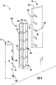
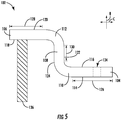
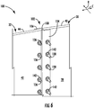
- FIGS. 4-6 illustrate one embodiment of the connection assembly 100. More specifically, FIG. 4 is an exploded perspective view of the connection assembly 100. FIG. 5 is a top view of a connector plate 102 of the connection assembly 100. FIG. 6 is an assembled perspective view of the connection assembly 100.
- the connection assembly 100 includes the connector plate 102, which couples a pair of adjacent tower section segments.
- the connector plate 102 couples the first tower section segment 30 and the second tower section segment 32.
- the connector plate 102 may also couple the second and third tower section segments 32, 34 or the first and third tower section segments 30, 34 as shown in FIG. 3 .
- the connector plate 102 includes a first connector plate portion 104, a second connector plate portion 106, and a third connector plate portion 108. As shown, the first connector plate portion 104 is spaced apart from the second connector plate portion 106, and the third connector plate portion 108 positioned between the first and second connector plate portions 104, 106. More specifically, the first and second connector plate portions 104, 106 are radially and circumferentially spaced apart. The third connector plate portion 108 is positioned radially and circumferentially between the first and second connector plate portions 104, 106. In this respect, the first and second connector plate portions 104, 106 may be oriented at an angle (e.g., a right angle) relative to the third connector plate portion 108.
- an angle e.g., a right angle
- a first arcuate portion 110 may couple the first and third connector plate portions 104, 108, and a second arcuate portion 112 may couple the second and third connector plate portions 106, 108.
- the connector plate 102 may be S-shaped.
- the S-shape of the bracket may conform to the rounded edges of the tower section segments.
- the third connector plate portion 108 may extend from the first connector plate portion 104 to the second connector plate portion 106.
- the connector plate 102 includes various surfaces.
- the first connector plate portion 104 includes a radially inner surface 114 radially spaced apart from a radially outer surface 116.
- the second connector plate portion 106 includes a radially inner surface 118 radially spaced apart from a radially outer surface 120.
- the third connector plate portion 108 includes a first circumferential surface 122 circumferentially spaced apart from a second circumferential surface 124. In alternate embodiments, the connector plate 102 may have different surfaces.
- the connector plate 102 also defines various lengths. As shown in FIG. 5 , the first connector plate portion 104 defines a circumferential length 126. Similarly, the second connector plate portion 106 defines a circumferential length 128. In particular embodiments, the circumferential lengths 126, 128 of the first and second connector plate portions 104, 106 may generally be the same.
- the third connector plate portion 108 defines a radial length 130, which may be shorter than circumferential lengths 126, 128 of the first and second connector plate portions 104, 106.
- the connector plate 102 also defines an axial length 132.
- the axial length 132 of the connector plate 102 may be the same as the axial lengths 48, 50 of the first and second tower section segments 30, 32. In alternate embodiments, however, the axial length 132 of the connector plate 102 may be less than the axial lengths 48, 50 of the first and second tower section segments 30, 32. In such embodiments, spacers (not shown) may be used to fill any gaps created by the disparate lengths of the connector plate 102 and the the first and second tower section segments 30, 32.
- the first connector plate portion 104 may define a plurality of mounting apertures 134 extending therethrough. Specifically, each of the mounting apertures 134 may extend from the radially inner surface 114 through the radially outer surface 116 of the first connector plate portion 104. As shown, the mounting apertures 134 are axially spaced apart and circumferentially aligned. In the embodiment shown in FIG. 4 , the first connector plate portion 104 defines five mounting apertures 134. Although, the first connector plate portion 104 may have more or less than five mounting apertures 134 in alternate embodiments. In alternate embodiments, the mounting apertures 134 may refer to any mounting apertures defined by any portion of the connector plate 102.
- the second connector plate portion 106 may include a plurality of studs 136 as shown in FIGS. 4-6 .
- the studs 136 may be axially spaced apart and circumferentially aligned.
- the studs 136 may extend radially inward (i.e., toward the axial centerline 28 shown in FIGS. 2 and 3 ) from the radially inner surface 118 of the second connector plate portion 106.
- the second connector plate portion 102 includes five studs 136.
- the second connector plate portion 106 may have more or less than five studs 136 in alternate embodiments.
- the studs 136 may be integral with the second connector plate portion 106.
- the studs 136 may be threaded.
- the studs 136 may refer to any studs on any portion of the connector plate 102.
- the connector plate 102 may be integrally formed. That is, the first, second, and third connector plate portions 104, 106, 108 are formed as a single component. In alternate embodiments, however, the connector plate 102 may be formed as a plurality of separate components. In some embodiments, the connector plate 102 may be formed as two separate L-shaped pieces that are coupled together via fasteners, welding, or any other suitable method. For example, one L-shaped piece may include the first connector plate portion 104 and a portion of the third connector plate portion 108. The other L-shaped piece may include the second connector plate portion 106 and a portion of the third connector plate portion 108. In this respect, the third connector plate portion 108 may be divided along a radially extending line 144 or a circumferentially extending line 146 shown in FIG. 3 .
- the connector plate 102 may couple the first and second tower section segments 30, 32.
- the first tower section segment 30 includes a plurality of studs 138 in the embodiment shown in FIG. 4 .
- the studs 138 extend through the mounting apertures 134 defined by the first connector plate portion 104.
- each of the studs 138 extends radially inward (i.e., toward the axial centerline 28 shown FIGS. 2 and 3 ) from the inner surface 38 of the first tower section segment 30.
- the studs 138 are axially spaced apart and circumferentially aligned proximate to an edge 56 of the first tower section segment 30 so as to align with the mounting apertures 134.
- the first tower section segment 30 includes as many studs 138 as the first connector plate portion 104 defines mounting apertures 134.
- the first tower section segment 30 includes five studs 138 in the embodiment shown in FIGS. 4 and 6 .
- the first tower section segment 30 may have more or less than five studs 138 in alternate embodiments.
- the studs 138 may be integral with the first tower section segment 30.
- the studs 138 may be threaded.
- the studs 138 may refer to any studs on any tower section segment.
- the second tower section segment 32 defines a plurality of mounting apertures 140 extending therethrough that receive the studs 136 on the second connector plate portion 106. Specifically, each of the mounting apertures 140 extends from the inner surface 42 of the second tower section segment 32 through the outer surface 44 of the second tower section segment 32.
- the mounting apertures 140 are axially spaced apart and circumferentially aligned proximate to an edge 58 of the second tower section segment 32 so as to align with the studs 136 on the second connector plate portion 104.
- the second tower section segment 32 defines as many mounting apertures 140 as the second connector plate portion 106 includes studs 136. In this respect, the second tower section segment 32 defines five mounting apertures 140 in the embodiment shown in FIG. 4 .
- the second tower section segment 32 may have more or less than five mounting apertures 140 in alternate embodiments.
- the mounting apertures 140 may refer to any mounting apertures defined be any tower section segment that extend from the radially inner surface thereof through the radially outer surface thereof.
- FIG. 6 illustrates the connection assembly 100 shown in FIG. 4 after assembly thereof.
- the first connector plate portion 104 couples to the first tower section segment 30, and the second connector plate portion 106 couples to the outer surface of the second tower section segment 32. More specifically, the radially outer surface 116 of the first connector plate portion 104 contacts the radially inner surface 38 of first tower section segment 30.
- each of the plurality of studs 138 on the first tower section segment 30 extends through one of the mounting apertures 134 in the first connector plate portion 104.
- the radially inner surface 118 of the second connector plate portion 106 contacts the radially outer surface 44 of second tower section segment 32.
- each of the plurality of studs 136 on the second connector plate portion 106 extends through one of the mounting apertures 140 in the second tower section segment 32.
- a fastener 142 e.g., a nut
- the third connector plate portion 108 is positioned in and extends through a vertically extending gap 60 ( FIG. 2 ) defined between the first and second tower section segments 30, 32.
- the connector plate 102 may be coupled to one of the first or second tower section segments prior to onsite assembly of the tower section to reduce assembly time.
- a portion of the connector plate 102 is positioned inside of the tower 12 and a portion of the connector plate 102 is positioned outside of the tower 12.
- the first connector plate portion 104 is positioned radially inward from the first and second tower section segments 30, 32 (i.e., in the interior space 36).
- the second connector plate portion 104 is positioned radially outward from the first and second tower section segments 30, 32.
- fasteners 142 may be installed onto all of the studs 136, 138 from inside of the tower 12 in the embodiment shown in FIGS. 4-6 . That is, the studs 136, 138 extend radially inward from the connector plate 102 and the first tower section segment 30, thereby permitting the fasteners 142 to threadingly engage the studs 136, 138 from within the interior space 36.
- FIG. 7 is an exploded top view of an alternate embodiment of the connection assembly 100. More specifically, the studs 136 extend radially outward (i.e., away from the axial centerline 28) from the radially outer surface 116 of the first connector plate portion 104.
- the second connector plate portion 106 defines the mounting apertures 134.
- the first tower section segment 30 defines the mounting apertures 140 extending therethrough, while the studs 138 extend radially outward from the second tower section segment 32.
- Each of studs 138 on the second tower section segment 32 extends through one of the mounting apertures 134 in the second connector plate portion 106.
- each of studs 136 on the first connector plate portion 104 extends through one of the mounting apertures 140 in the first tower section segment 30.
- the fasteners 142 may threadingly engage each of the studs 136, 138 from outside of the tower 12.
- FIG. 8 is an exploded top view of a further embodiment of the connection assembly 100. More specifically, the studs 136 extend radially outward from the radially outer surface 116 of the first connector plate portion 104 and radially inward from the radially inner surface 118 of the second connector plate portion 106. In this respect, the first and second tower section segments 30, 32 define the mounting apertures 140. Each of studs 136 on the first and second connector plate portions 104, 106 extends through one of the mounting apertures 140 in the first and second tower section segments 30, 32. The fasteners 142 may threadingly engage each of the studs 136 on the second connector plate portion 106 from the interior space 36. Conversely, the fasteners 142 may threadingly engage each of the studs 136 on the first connector plate portion 104 from outside of the tower 12.
- FIG. 9 is an exploded top view of yet another embodiment of the connection assembly 100. More specifically, the first and second connector plate portions 104, 106 define the mounting apertures 134.
- the studs 138 extend radially inward from the radially inner surface 38 of the first tower section segment 30 and radially outward from the radially outer surface 44 of the second tower section segment 32.
- Each of studs 138 on the first and second tower section segments 30, 32 extends through one of the mounting apertures 134 in the first and second connector plate portions 104, 106.
- the fasteners 142 may threadingly engage each of the studs 136 on the first tower section segment 30 from the interior space 36. Conversely, the fasteners 142 may threadingly engage each of the studs 136 on the second tower section segment 32 from outside of the tower 12.
- the studs 136 extend outwardly from the connector plate 102, and the studs 138 extend outwardly from the first and/or second tower section segments 30, 32.
- the studs 136, 138 may be press-fit or welded to the connector plate 102 and/or second tower section segments 30, 32. Nevertheless, the studs 136, 138 maybe coupled to the connector plate 102 and/or second tower section segments 30, 32 in a slide fit relationship (e.g., bolts) or any other suitable manner.
- the connector plate 102 may be coupled to the first and second tower section segments 30, 32 in any suitable manner.
- the connector plate 102 may be welded to the first and second tower section segments 30, 32.
- the welds maybe inside or outside of the tower 12.
- some embodiments of the connector plate 102 may be divided into two L-shaped portions along the circumferentially extending lined 146. In such embodiments, the fastener coupling the L-shaped portions may clamp the the first and second tower section segments 30, 32 together, thereby creating a friction-based connection.
- the connector plate 102 and the first and second tower section segments 30, 32 may be coupled via hemming, crimping, or any other suitable press-fit operation.
- connection assembly 100 includes the connector plate 102, which couples adjacent tower section segments.
- the first connector plate portion 104 couples to the first tower section segment 30, and the second connector plate portion 106 couples to the second tower section segment 32.
- the connection assembly 100 disclosed herein unlike conventional connection assemblies, does not require positioning of a spacer and/or filler between flanges welded to the adjacent tower section segments. As such, the connection assembly 100 reduces the assembly time of the tower 12.
Landscapes
- Engineering & Computer Science (AREA)
- General Engineering & Computer Science (AREA)
- Architecture (AREA)
- Mechanical Engineering (AREA)
- Life Sciences & Earth Sciences (AREA)
- Chemical & Material Sciences (AREA)
- Structural Engineering (AREA)
- Civil Engineering (AREA)
- Combustion & Propulsion (AREA)
- Sustainable Energy (AREA)
- Sustainable Development (AREA)
- Materials Engineering (AREA)
- Wood Science & Technology (AREA)
- Physics & Mathematics (AREA)
- Electromagnetism (AREA)
- Wind Motors (AREA)
Abstract
Description
- The present disclosure generally relates to wind turbines. More particularly, the present disclosure relates to connection assemblies for towers of wind turbines.
- Wind power is considered one of the cleanest, most environmentally friendly energy sources presently available, and wind turbines have gained increased attention in this regard. A modern wind turbine typically includes a tower, a nacelle mounted on the tower, a generator positioned in the nacelle, and one or more rotor blades. The one or more rotor blades convert the kinetic energy of wind into mechanical energy using known airfoil principles. A shaft transmits the mechanical energy from the rotor blades to the generator. The generator then converts the mechanical energy to electrical energy that may be supplied to a utility grid.
- The tower may be constructed from a plurality of tower sections. In particular, each of the tower sections may be stacked, e.g., vertically, and coupled together to form the tower. Each of the tower sections may, in turn, be formed from a plurality of tower section segments. Specifically, the tower section segments may be annularly arranged and coupled together to form the tower section.
- Each pair of adjacent tower section segments may be coupled by a connection assembly. More specifically, conventional connection assemblies may include a flange welded to each tower section segment being coupled. A spacer may then be positioned between the flanges before coupling the flanges with bolts. Furthermore, it may be necessary to place a filler material in the joint between the adjacent tower section segments. In this respect, the assembly of the tower section using conventional connection assemblies may be time-consuming, thereby increasing the cost of the wind turbine.
- Accordingly, improved wind turbines, and, in particular, improved connection assemblies for wind turbine towers, are desired in the art. Specifically, connection assemblies that do not require the use of spacers and/or filler materials and that are relatively more efficient to use would be advantageous.
- Various aspects and advantages of the technology will be set forth in part in the following description, or may be clear from the description, or may be learned through practice of the technology.
- In one aspect, the present disclosure is directed to a connection assembly for a tower of a wind turbine. The connection assembly includes a first tower section segment having an inner surface spaced apart from an outer surface. A second tower section segment is positioned adjacent to the first tower section segment and includes an inner surface spaced apart from an outer surface. The first tower section segment and the second tower section segment define a vertically extending gap therebetween. A connector plate includes a first connector plate portion, a second connector plate portion spaced apart from the first connector plate portion, and a third connector plate portion positioned between the first connector plate portion and the second connector plate portion. The first connector plate portion couples to the first tower section segment. The second connector plate portion couples to the second tower section segment. The third connector plate portion extends through the vertically extending gap.
- In another aspect, the present disclosure is directed to a wind turbine having a nacelle and a rotor coupled to the nacelle. The rotor includes a hub and at least one rotor blade extending from the hub. A tower supports the nacelle and includes a first tower section segment having an inner surface spaced apart from an outer surface. A second tower section segment is positioned adjacent to the first tower section segment. The second tower section segment includes an inner surface spaced apart from an outer surface. The first tower section segment and the second tower section segment define a vertically extending gap therebetween. A connector plate includes a first connector plate portion, a second connector plate portion spaced apart from the first connector plate portion, and a third connector plate portion positioned between the first connector plate portion and the second connector plate portion. The first connector plate portion couples to the first tower section segment. The second connector plate portion couples to the second tower section segment. The third connector plate portion extends through the vertically extending gap.
- Various features, aspects and advantages of the present technology will become better understood with reference to the following description and appended claims. The accompanying drawings, which are incorporated in and constitute a part of this specification, illustrate embodiments of the technology and, together with the description, serve to explain the principles of the technology.
-
-
FIG. 1 is a perspective view of an exemplary wind turbine in accordance with embodiments of the present disclosure; -
FIG. 2 is a front view of a tower section of a tower of the wind turbine in accordance with embodiments of the present disclosure; -
FIG. 3 is a top view of the tower section, illustrating a plurality of tower section segments in accordance with embodiments of the present disclosure; -
FIG. 4 is an exploded perspective view of one embodiment of a connection assembly for coupling adjacent tower section segments in accordance with embodiments of the present disclosure; -
FIG. 5 is a top view of a connector plate of the connection assembly in accordance with embodiments of the present disclosure; -
FIG. 6 is an assembled perspective view of the embodiment of the connection assembly shown inFIG. 4 in accordance with embodiments of the present disclosure; -
FIG. 7 is an exploded top view of another embodiment of the connection assembly for coupling adjacent tower section segments in accordance with embodiments of the present disclosure; -
FIG. 8 is an exploded top view of further embodiment of the connection assembly for coupling adjacent tower section segments in accordance with embodiments of the present disclosure; and -
FIG. 9 is an exploded top view of yet another embodiment of the connection assembly for coupling adjacent tower section segments in accordance with embodiments of the present disclosure. - Repeat use of reference characters in the present specification and drawings is intended to represent the same or analogous features or elements of the present technology.
- Reference will now be made in detail to present embodiments of the technology, one or more examples of which are illustrated in the accompanying drawings. The detailed description uses numerical and letter designations to refer to features in the drawings. Like or similar designations in the drawings and description have been used to refer to like or similar parts of the technology. As used herein, the terms "first", "second", and "third" may be used interchangeably to distinguish one component from another and are not intended to signify location or importance of the individual components. The terms "upstream" and "downstream" refer to the relative direction with respect to fluid flow in a fluid pathway. For example, "upstream" refers to the direction from which the fluid flows, and "downstream" refers to the direction to which the fluid flows.
- Each example is provided by way of explanation of the technology, not limitation of the technology. In fact, it will be apparent to those skilled in the art that modifications and variations can be made in the present technology without departing from the scope or spirit thereof. For instance, features illustrated or described as part of one embodiment may be used on another embodiment to yield a still further embodiment. Thus, it is intended that the present technology covers such modifications and variations as come within the scope of the appended claims and their equivalents.
- Referring now to the drawings,
FIG. 1 illustrates a perspective view of one embodiment of anexemplary wind turbine 10 in accordance with the present disclosure. As shown, thewind turbine 10 generally includes atower 12 extending from asupport surface 14, anacelle 16 mounted on thetower 12, and arotor 18 coupled to thenacelle 16. Therotor 18 includes arotatable hub 20 and at least onerotor blade 22 coupled to and extending outwardly from thehub 20. For example, in the embodiment shown inFIG. 1 , therotor 18 includes threerotor blades 22. In alternative embodiments, however, therotor 18 may include more or less than threerotor blades 22. Eachrotor blade 22 may be spaced about thehub 20 to facilitate rotating therotor 18 to convert kinetic energy from the wind into usable mechanical energy, and subsequently, electrical energy. For instance, thehub 20 may be rotatably coupled to anelectric generator 24 positioned within thenacelle 16. - As shown in
FIG. 1 , thetower 12 may include a plurality oftower sections 26. In particular, thetower sections 26 are stacked (e.g., vertically) and coupled together so that thetower 12 positions the nacelle 16 a desired distance away from thesupport surface 14. In the embodiment shown inFIG. 1 , thetower 12 includes fivetower sections 26. Alternate embodiments of thetower 12, however, may include more or less than fivetower sections 26. -
FIGS. 2 and 3 illustrate one of thetower sections 26 shown inFIG. 1 in greater detail. Specifically,FIG. 2 is a front view of one of thetower sections 26, andFIG. 3 is a top view of one of thetower sections 26. As shown, thetower section 26 defines anaxial centerline 28 that extends therethrough. In this respect, thetower section 26 defines an axial direction A, a radial direction R, and a circumferential direction C. In general, the axial direction A extends parallel to theaxial centerline 28, the radial direction R extends orthogonally outward from theaxial centerline 28, and the circumferential direction C extends concentrically around theaxial centerline 28. - The
tower section 26 may be formed from a plurality of tower section segments. In the embodiment shown inFIGS. 2 and 3 , thetower section 26 includes a firsttower section segment 30, a secondtower section segment 32, and a thirdtower section segment 34. As best illustrated inFIG. 3 , the first, second, and thirdtower section segments axial centerline 28 and are radially spaced apart from theaxial centerline 28. In this respect, thetower section 26 defines aninterior space 36 through which, e.g., wiring (not shown) coupling theelectric generator 24 to a power grid (not shown) may extend and in which wind turbine equipment and platforms may be positioned. In alternate embodiments, however, thetower section 26 may have more or less than three tower section segments. - Each tower section segment includes inner and outer surfaces. In the embodiment shown in
FIGS. 2 and 3 , the firsttower section segment 30 includes aninner surface 38 radially spaced apart from anouter surface 40. The secondtower section segment 32 similarly includes aninner surface 42 radially spaced apart from anouter surface 44. The thirdtower section segment 34 similarly includes aninner surface 45 radially spaced apart from anouter surface 46. As shown, theouter surfaces tower section segments inner surfaces tower section segments inner surfaces interior space 36 defined by thetower section 26. The edges of the tower section segments may rectangular as shown inFIG. 3 or rounded as shown inFIG. 4 . - The first, second, and third
tower section segments tower section 26 in the axial direction A. As shown inFIG. 2 , the firsttower section segment 30 defines anaxial length 48. Similarly, the secondtower section segment 32 defines anaxial length 50. Although not shown, the thirdtower section segment 34 also defines an axial length. In an exemplary embodiment, theaxial lengths - As best illustrated in
FIG. 3 , each of the first, second, and thirdtower section segments more flanges 52. In certain embodiments, oneflange 52 may be positioned at each axial end, e.g., atop end 62 and a bottom end 64 (FIG. 2 ), of the first, second, and thirdtower section segments flange 52 generally extends radially inward and defines one or more mountingapertures 54 that may receive fasteners, such as bolts or other suitable mechanical fasteners. In this respect, the fasteners may couple eachflange 52 of the first, second, and thirdtower section segments adjacent tower section 26. For example, theflange 52 on the top end of the firsttower section segment 30 shown inFIG. 3 may couple to a flange on the bottom end of one of the tower section segments of anadjacent tower section 26. - As shown in
FIG. 3 , aconnection assembly 100 couples each adjacent pair of the tower section segments. In particular, oneconnection assembly 100 couples the first and secondtower section segments connection assembly 100 couples the second and thirdtower section segments further connection assembly 100 couples the first and thirdtower section segments FIG. 3 includes threeconnection assemblies 100, alternate embodiments of thetower section 26 may include more or less than threeconnection assemblies 100 depending on the number of tower section segments. -
FIGS. 4-6 illustrate one embodiment of theconnection assembly 100. More specifically,FIG. 4 is an exploded perspective view of theconnection assembly 100.FIG. 5 is a top view of aconnector plate 102 of theconnection assembly 100.FIG. 6 is an assembled perspective view of theconnection assembly 100. - The
connection assembly 100 includes theconnector plate 102, which couples a pair of adjacent tower section segments. In the embodiment shown inFIGS. 4-6 , theconnector plate 102 couples the firsttower section segment 30 and the secondtower section segment 32. Nevertheless, theconnector plate 102 may also couple the second and thirdtower section segments tower section segments FIG. 3 . - The
connector plate 102 includes a firstconnector plate portion 104, a secondconnector plate portion 106, and a thirdconnector plate portion 108. As shown, the firstconnector plate portion 104 is spaced apart from the secondconnector plate portion 106, and the thirdconnector plate portion 108 positioned between the first and secondconnector plate portions connector plate portions connector plate portion 108 is positioned radially and circumferentially between the first and secondconnector plate portions connector plate portions connector plate portion 108. In the embodiment shown inFIGS. 4-6 , a firstarcuate portion 110 may couple the first and thirdconnector plate portions arcuate portion 112 may couple the second and thirdconnector plate portions connector plate 102 may be S-shaped. For example, the S-shape of the bracket may conform to the rounded edges of the tower section segments. In alternate embodiments, however, the thirdconnector plate portion 108 may extend from the firstconnector plate portion 104 to the secondconnector plate portion 106. - The
connector plate 102 includes various surfaces. In the embodiment shown inFIG. 5 , the firstconnector plate portion 104 includes a radiallyinner surface 114 radially spaced apart from a radiallyouter surface 116. Similarly, the secondconnector plate portion 106 includes a radiallyinner surface 118 radially spaced apart from a radiallyouter surface 120. The thirdconnector plate portion 108 includes a firstcircumferential surface 122 circumferentially spaced apart from a secondcircumferential surface 124. In alternate embodiments, theconnector plate 102 may have different surfaces. - The
connector plate 102 also defines various lengths. As shown inFIG. 5 , the firstconnector plate portion 104 defines acircumferential length 126. Similarly, the secondconnector plate portion 106 defines acircumferential length 128. In particular embodiments, thecircumferential lengths connector plate portions connector plate portion 108 defines aradial length 130, which may be shorter thancircumferential lengths connector plate portions circumferential length 126 of the firstconnector plate portion 104, thecircumferential length 128 of secondconnector plate portion 106, theradial length 130 of the thirdconnector plate portion 108, and/or theaxial length 132 of theconnector plate 102. As shown inFIG. 2 , theconnector plate 102 also defines anaxial length 132. Theaxial length 132 of theconnector plate 102 may be the same as theaxial lengths tower section segments axial length 132 of theconnector plate 102 may be less than theaxial lengths tower section segments connector plate 102 and the the first and secondtower section segments - As shown in
FIGS. 4 and5 , the firstconnector plate portion 104 may define a plurality of mountingapertures 134 extending therethrough. Specifically, each of the mountingapertures 134 may extend from the radiallyinner surface 114 through the radiallyouter surface 116 of the firstconnector plate portion 104. As shown, the mountingapertures 134 are axially spaced apart and circumferentially aligned. In the embodiment shown inFIG. 4 , the firstconnector plate portion 104 defines five mountingapertures 134. Although, the firstconnector plate portion 104 may have more or less than five mountingapertures 134 in alternate embodiments. In alternate embodiments, the mountingapertures 134 may refer to any mounting apertures defined by any portion of theconnector plate 102. - The second
connector plate portion 106 may include a plurality ofstuds 136 as shown inFIGS. 4-6 . In particular, thestuds 136 may be axially spaced apart and circumferentially aligned. Furthermore, thestuds 136 may extend radially inward (i.e., toward theaxial centerline 28 shown inFIGS. 2 and 3 ) from the radiallyinner surface 118 of the secondconnector plate portion 106. In the embodiment shown inFIGS. 4 and5 , the secondconnector plate portion 102 includes fivestuds 136. Although, the secondconnector plate portion 106 may have more or less than fivestuds 136 in alternate embodiments. Thestuds 136 may be integral with the secondconnector plate portion 106. Furthermore, thestuds 136 may be threaded. In alternate embodiments, thestuds 136 may refer to any studs on any portion of theconnector plate 102. - In some embodiments, the
connector plate 102 may be integrally formed. That is, the first, second, and thirdconnector plate portions connector plate 102 may be formed as a plurality of separate components. In some embodiments, theconnector plate 102 may be formed as two separate L-shaped pieces that are coupled together via fasteners, welding, or any other suitable method. For example, one L-shaped piece may include the firstconnector plate portion 104 and a portion of the thirdconnector plate portion 108. The other L-shaped piece may include the secondconnector plate portion 106 and a portion of the thirdconnector plate portion 108. In this respect, the thirdconnector plate portion 108 may be divided along aradially extending line 144 or acircumferentially extending line 146 shown inFIG. 3 . - As mentioned above, the
connector plate 102 may couple the first and secondtower section segments tower section segment 30 includes a plurality ofstuds 138 in the embodiment shown inFIG. 4 . As will be discussed in greater detail below, thestuds 138 extend through the mountingapertures 134 defined by the firstconnector plate portion 104. As shown, each of thestuds 138 extends radially inward (i.e., toward theaxial centerline 28 shownFIGS. 2 and 3 ) from theinner surface 38 of the firsttower section segment 30. Thestuds 138 are axially spaced apart and circumferentially aligned proximate to anedge 56 of the firsttower section segment 30 so as to align with the mountingapertures 134. In general, the firsttower section segment 30 includes asmany studs 138 as the firstconnector plate portion 104 defines mountingapertures 134. In this respect, the firsttower section segment 30 includes fivestuds 138 in the embodiment shown inFIGS. 4 and6 . Although, the firsttower section segment 30 may have more or less than fivestuds 138 in alternate embodiments. Thestuds 138 may be integral with the firsttower section segment 30. Furthermore, thestuds 138 may be threaded. In alternate embodiments, thestuds 138 may refer to any studs on any tower section segment. - The second
tower section segment 32 defines a plurality of mountingapertures 140 extending therethrough that receive thestuds 136 on the secondconnector plate portion 106. Specifically, each of the mountingapertures 140 extends from theinner surface 42 of the secondtower section segment 32 through theouter surface 44 of the secondtower section segment 32. The mountingapertures 140 are axially spaced apart and circumferentially aligned proximate to anedge 58 of the secondtower section segment 32 so as to align with thestuds 136 on the secondconnector plate portion 104. In general, the secondtower section segment 32 defines as many mountingapertures 140 as the secondconnector plate portion 106 includesstuds 136. In this respect, the secondtower section segment 32 defines five mountingapertures 140 in the embodiment shown inFIG. 4 . Although, the secondtower section segment 32 may have more or less than five mountingapertures 140 in alternate embodiments. In alternate embodiments, the mountingapertures 140 may refer to any mounting apertures defined be any tower section segment that extend from the radially inner surface thereof through the radially outer surface thereof. - As mentioned above,
FIG. 6 illustrates theconnection assembly 100 shown inFIG. 4 after assembly thereof. As shown, the firstconnector plate portion 104 couples to the firsttower section segment 30, and the secondconnector plate portion 106 couples to the outer surface of the secondtower section segment 32. More specifically, the radiallyouter surface 116 of the firstconnector plate portion 104 contacts the radiallyinner surface 38 of firsttower section segment 30. In this respect, each of the plurality ofstuds 138 on the firsttower section segment 30 extends through one of the mountingapertures 134 in the firstconnector plate portion 104. Similarly, the radiallyinner surface 118 of the secondconnector plate portion 106 contacts the radiallyouter surface 44 of secondtower section segment 32. As such, each of the plurality ofstuds 136 on the secondconnector plate portion 106 extends through one of the mountingapertures 140 in the secondtower section segment 32. A fastener 142 (e.g., a nut) may threadingly engage each of thestuds tower section segment 30, theconnector plate 102, and the secondtower section segment 32. Furthermore, the thirdconnector plate portion 108 is positioned in and extends through a vertically extending gap 60 (FIG. 2 ) defined between the first and secondtower section segments connector plate 102 may be coupled to one of the first or second tower section segments prior to onsite assembly of the tower section to reduce assembly time. - As shown in
FIG. 6 , a portion of theconnector plate 102 is positioned inside of thetower 12 and a portion of theconnector plate 102 is positioned outside of thetower 12. In particular, the firstconnector plate portion 104 is positioned radially inward from the first and secondtower section segments 30, 32 (i.e., in the interior space 36). Conversely, the secondconnector plate portion 104 is positioned radially outward from the first and secondtower section segments fasteners 142 may be installed onto all of thestuds tower 12 in the embodiment shown inFIGS. 4-6 . That is, thestuds connector plate 102 and the firsttower section segment 30, thereby permitting thefasteners 142 to threadingly engage thestuds interior space 36. -
FIG. 7 is an exploded top view of an alternate embodiment of theconnection assembly 100. More specifically, thestuds 136 extend radially outward (i.e., away from the axial centerline 28) from the radiallyouter surface 116 of the firstconnector plate portion 104. The secondconnector plate portion 106 defines the mountingapertures 134. In this respect, the firsttower section segment 30 defines the mountingapertures 140 extending therethrough, while thestuds 138 extend radially outward from the secondtower section segment 32. Each ofstuds 138 on the secondtower section segment 32 extends through one of the mountingapertures 134 in the secondconnector plate portion 106. Furthermore, each ofstuds 136 on the firstconnector plate portion 104 extends through one of the mountingapertures 140 in the firsttower section segment 30. Thefasteners 142 may threadingly engage each of thestuds tower 12. -
FIG. 8 is an exploded top view of a further embodiment of theconnection assembly 100. More specifically, thestuds 136 extend radially outward from the radiallyouter surface 116 of the firstconnector plate portion 104 and radially inward from the radiallyinner surface 118 of the secondconnector plate portion 106. In this respect, the first and secondtower section segments apertures 140. Each ofstuds 136 on the first and secondconnector plate portions apertures 140 in the first and secondtower section segments fasteners 142 may threadingly engage each of thestuds 136 on the secondconnector plate portion 106 from theinterior space 36. Conversely, thefasteners 142 may threadingly engage each of thestuds 136 on the firstconnector plate portion 104 from outside of thetower 12. -
FIG. 9 is an exploded top view of yet another embodiment of theconnection assembly 100. More specifically, the first and secondconnector plate portions apertures 134. In this respect, thestuds 138 extend radially inward from the radiallyinner surface 38 of the firsttower section segment 30 and radially outward from the radiallyouter surface 44 of the secondtower section segment 32. Each ofstuds 138 on the first and secondtower section segments apertures 134 in the first and secondconnector plate portions fasteners 142 may threadingly engage each of thestuds 136 on the firsttower section segment 30 from theinterior space 36. Conversely, thefasteners 142 may threadingly engage each of thestuds 136 on the secondtower section segment 32 from outside of thetower 12. - As discussed in greater detail above, the
studs 136 extend outwardly from theconnector plate 102, and thestuds 138 extend outwardly from the first and/or secondtower section segments studs connector plate 102 and/or secondtower section segments studs connector plate 102 and/or secondtower section segments - In the embodiments shown in
FIGS. 4-9 , various combinations of studs and fasteners couple theconnector plate 102 to the first and secondtower section segments connector plate 102 may be coupled to the first and secondtower section segments connector plate 102 may be welded to the first and secondtower section segments tower 12. As mentioned above, some embodiments of theconnector plate 102 may be divided into two L-shaped portions along the circumferentially extending lined 146. In such embodiments, the fastener coupling the L-shaped portions may clamp the the first and secondtower section segments connector plate 102 and the first and secondtower section segments - As discussed in greater detail above, the
connection assembly 100 includes theconnector plate 102, which couples adjacent tower section segments. In the embodiments shown inFIGS. 4-9 , for example, the firstconnector plate portion 104 couples to the firsttower section segment 30, and the secondconnector plate portion 106 couples to the secondtower section segment 32. In this respect, theconnection assembly 100 disclosed herein, unlike conventional connection assemblies, does not require positioning of a spacer and/or filler between flanges welded to the adjacent tower section segments. As such, theconnection assembly 100 reduces the assembly time of thetower 12. - This written description uses examples to disclose the technology, including the preferred mode, and also to enable any person skilled in the art to practice the technology, including making and using any devices or systems and performing any incorporated methods. The patentable scope of the technology is defined by the claims, and may include other examples that occur to those skilled in the art. Such other examples are intended to be within the scope of the claims if they include structural elements that do not differ from the literal language of the claims, or if they include equivalent structural elements with insubstantial differences from the literal language of the claims.
- Various aspects and embodiments of the present invention are defined by the following numbered clauses:
- 1. A connection assembly for a tower of a wind turbine, the connection assembly comprising:
- a first tower section segment comprising an inner surface spaced apart from an outer surface;
- a second tower section segment positioned adjacent to the first tower section segment, the second tower section segment comprising an inner surface spaced apart from an outer surface, wherein the first tower section segment and the second tower section segment define a vertically extending gap therebetween and at least partially define a tower interior; and
- a connector plate comprising a first connector plate portion, a second connector plate portion spaced apart from the first connector plate portion, and a third connector plate portion positioned between the first connector plate portion and the second connector plate portion;
- wherein the first connector plate portion couples to the first tower section segment, the second connector plate portion couples to the second tower section segment, and the third connector plate portion extends through the vertically extending gap.
- 2. The connection assembly of clause 1, wherein the first connector plate portion is radially spaced apart from the second connector plate portion, and wherein the first connector plate portion contacts the radially inner surface of the first tower section segment and the second connector plate portion contacts the radially outer surface to the second tower section segment.
- 3. The connection assembly of any preceding clause, wherein the third connector plate portion is oriented at angle relative to the first connector plate portion and the second connector plate portion.
- 4. The connection assembly of any preceding clause, wherein the connector plate is S-shaped.
- 5. The connection assembly of any preceding clause, wherein the first tower section segment comprises a vertical length, the second tower section segment comprises a vertical length, and the connector plate comprises a vertical length, and wherein the vertical length of the first tower section segment, the vertical length of the second tower section segment, and the vertical length of the connector plate are equal.
- 6. The connection assembly of any preceding clause, wherein the first tower section segment comprises a plurality of studs and the second tower section segment defines a plurality of mounting apertures extending therethrough.
- 7. The connection assembly of any preceding clause, wherein the first connector plate portion defines a plurality of mounting apertures and the second connector plate portion comprises a plurality of studs.
- 8. The connection assembly of any preceding clause, wherein each of the plurality of studs on the first tower section segment extends through one of the plurality of apertures defined by the first connector plate portion, and wherein each of the plurality of studs on the second connector plate portion extends through one of the plurality of apertures defined by the second tower section segment.
- 9. The connection assembly of any preceding clause, wherein the first tower section segment and the second tower section segment each define a plurality of mounting apertures extending therethrough.
- 10. The connection assembly of any preceding clause, wherein the first connector plate portion and the second connector plate portion each comprise a plurality of studs, wherein each of the plurality of studs on the first connector plate portion extends through one of the plurality of apertures defined by the first tower section segment, and wherein each of the plurality of studs on the second connector plate portion extends through one of the plurality of apertures defined by the second tower section segment.
- 11. The connection assembly of any preceding clause, wherein the first connector plate portion and the second connector plate portion each define a plurality of mounting apertures.
- 12. The connection assembly of any preceding clause, wherein the first tower section segment and the second tower section segment each comprise a plurality of studs, wherein each of the plurality of studs on the first tower section segment extends through one of the plurality of apertures defined by the first connector plate portion, and wherein each of the plurality of studs on the second tower section segment extends through one of the plurality of apertures defined by the second connector plate portion.
- 13. A wind turbine, comprising:
- a nacelle;
- a rotor coupled to the nacelle, the rotor comprising a hub and at least one rotor blade extending from the hub; and
- a tower supporting the nacelle, the tower comprising:
- a first tower section segment comprising an inner surface spaced apart from an outer surface;
- a second tower section segment positioned adjacent to the first tower section segment, the second tower section segment comprising an inner surface spaced apart from an outer surface, wherein the first tower section segment and the second tower section segment define a vertically extending gap therebetween; and
- a connector plate comprising a first connector plate portion, a second connector plate portion spaced apart from the first connector plate portion, and a third connector plate portion positioned between the first connector plate portion and the second connector plate portion;
- wherein the first connector plate portion couples to the first tower section segment, the second connector plate portion couples to the second tower section segment, and the third connector plate portion extends through the vertically extending gap.
- 14. The wind turbine of any preceding clause, wherein the first connector plate portion is radially spaced apart from the second connector plate portion, and wherein the third connector plate portion is oriented at an angle relative to the first connector plate portion and the second connector plate portion.
- 15. The wind turbine of any preceding clause, wherein the first tower section segment comprises a vertical length, the second tower section segment comprises a vertical length, and the connector plate comprises a vertical length, and wherein the vertical length of the first tower section segment, the vertical length of the second tower section segment, and the vertical length of the connector plate are the same.
- 16. The wind turbine of any preceding clause, wherein the first tower section segment comprises a plurality of studs and the second tower section segment defines a plurality of mounting apertures extending therethrough.
- 17. The wind turbine of any preceding clause, wherein the first connector plate portion defines a plurality of mounting apertures and the second connector plate portion comprises a plurality of studs.
- 18. The wind turbine of any preceding clause, wherein each of the plurality of studs on the first tower section segment extends through one of the plurality of apertures defined by the first connector plate portion, and wherein each of the plurality of studs on the second connector plate portion extends through one of the plurality of apertures defined by the second tower section segment.
- 19. The wind turbine of any preceding clause, wherein at least two of the first tower section segment, the second tower section segment, the first connector plate portion, or the second connector plate portion each define a plurality of apertures extending therethrough.
- 20. The wind turbine of any preceding clause, wherein the first connector plate portion and the second connector plate portion each define a plurality of mounting apertures.
Claims (15)
- A connection assembly (100) for a tower (12) of a wind turbine (10), the connection assembly (100) comprising:a first tower section segment (30) comprising an inner surface (38) spaced apart from an outer surface (40);a second tower section segment (32) positioned adjacent to the first tower section segment (30), the second tower section segment (32) comprising an inner surface (42) spaced apart from an outer surface (44), wherein the first tower section segment (30) and the second tower section segment (32) define a vertically extending gap (60) therebetween and at least partially define a tower interior (36); anda connector plate (102) comprising a first connector plate portion (104), a second connector plate portion (106) spaced apart from the first connector plate portion (104), and a third connector plate portion (108) positioned between the first connector plate portion (104) and the second connector plate portion (106);wherein the first connector plate portion (104) couples to the first tower section segment (30), the second connector plate portion (106) couples to the second tower section segment (32), and the third connector plate portion (108) extends through the vertically extending gap (60).
- The connection assembly (100) of claim 1, wherein the first connector plate portion (104) is radially spaced apart from the second connector plate portion (106), and wherein the first connector plate portion (104) contacts the radially inner surface (38) of the first tower section segment (30) and the second connector plate portion (106) contacts the radially outer surface (44) to the second tower section segment (32).
- The connection assembly (100) of claim 2, wherein the third connector plate portion (108) is oriented at angle relative to the first connector plate portion (104) and the second connector plate portion (106).
- The connection assembly (100) of any preceding claim, wherein the connector plate (102) is S-shaped.
- The connection assembly (100) of any preceding claim, wherein the first tower section segment (30) comprises a vertical length (48), the second tower section segment (32) comprises a vertical length (50), and the connector plate (102) comprises a vertical length (132), and wherein the vertical length (48) of the first tower section segment (30), the vertical length (50) of the second tower section segment (32), and the vertical length (132) of the connector plate (102) are equal.
- The connection assembly (100) of any preceding claim, wherein the first tower section segment (30) comprises a plurality of studs (138) and the second tower section segment (32) defines a plurality of mounting apertures (140) extending therethrough.
- The connection assembly (100) of any preceding claim, wherein the first connector plate portion (104) defines a plurality of mounting apertures (134) and the second connector plate portion (106) comprises a plurality of studs (136).
- The connection assembly (100) of any preceding claim, wherein each of the plurality of studs (138) on the first tower section segment (30) extends through one of the plurality of apertures (134) defined by the first connector plate portion (104), and wherein each of the plurality of studs (136) on the second connector plate portion (106) extends through one of the plurality of apertures (140) defined by the second tower section segment (32).
- The connection assembly (100) of any preceding claim, wherein the first tower section segment (30) and the second tower section segment (32) each define a plurality of mounting apertures (140) extending therethrough.
- The connection assembly (100) of claim 9, wherein the first connector plate portion (104) and the second connector plate portion (106) each comprise a plurality of studs (136), wherein each of the plurality of studs (136) on the first connector plate portion (104) extends through one of the plurality of apertures (140) defined by the first tower section segment (30), and wherein each of the plurality of studs (136) on the second connector plate portion (106) extends through one of the plurality of apertures (140) defined by the second tower section segment (32).
- The connection assembly (100) of any preceding claim, wherein the first connector plate portion (104) and the second connector plate portion (106) each define a plurality of mounting apertures (134).
- The connection assembly (100) of any preceding claim, wherein the first tower section segment (30) and the second tower section segment (32) each comprise a plurality of studs (138), wherein each of the plurality of studs (138) on the first tower section segment (30) extends through one of the plurality of apertures (134) defined by the first connector plate portion (104), and wherein each of the plurality of studs (138) on the second tower section segment (32) extends through one of the plurality of apertures (134) defined by the second connector plate portion (106).
- A wind turbine (10), comprising:a nacelle (16);a rotor (18) coupled to the nacelle (16), the rotor (18) comprising a hub (20) and at least one rotor blade (22) extending from the hub (20); anda tower (12) supporting the nacelle (16), the tower (12) comprising:a first tower section segment (30) comprising an inner surface (38) spaced apart from an outer surface (40);a second tower section segment (32) positioned adjacent to the first tower section segment (30), the second tower section segment (32) comprising an inner surface (42) spaced apart from an outer surface (44), wherein the first tower section segment (30) and the second tower section segment (32) define a vertically extending gap (60) therebetween; anda connector plate (102) comprising a first connector plate portion (104), a second connector plate portion (106) spaced apart from the first connector plate portion (104), and a third connector plate portion (108) positioned between the first connector plate portion (104) and the second connector plate portion (106);wherein the first connector plate portion (104) couples to the first tower section segment (30), the second connector plate portion (106) couples to the second tower section segment (32), and the third connector plate portion (108) extends through the vertically extending gap (60).
- The wind turbine (10) of claim 13, wherein the first connector plate portion (104) is radially spaced apart from the second connector plate portion (106), and wherein the third connector plate portion (108) is oriented at an angle relative to the first connector plate portion (104) and the second connector plate portion (106).
- The wind turbine (10) of claim 13 or 14, wherein the first tower section segment (30) comprises a vertical length (48), the second tower section segment (32) comprises a vertical length (50), and the connector plate (102) comprises a vertical length (132), and wherein the vertical length (48) of the first tower section segment (30), the vertical length (50) of the second tower section segment (32), and the vertical length (132) of the connector plate (102) are the same.
Applications Claiming Priority (1)
| Application Number | Priority Date | Filing Date | Title |
|---|---|---|---|
| US15/363,338 US10053886B2 (en) | 2016-11-29 | 2016-11-29 | Connection assembly for wind turbine tower |
Publications (2)
| Publication Number | Publication Date |
|---|---|
| EP3327284A1 true EP3327284A1 (en) | 2018-05-30 |
| EP3327284B1 EP3327284B1 (en) | 2022-07-20 |
Family
ID=60452487
Family Applications (1)
| Application Number | Title | Priority Date | Filing Date |
|---|---|---|---|
| EP17203379.7A Active EP3327284B1 (en) | 2016-11-29 | 2017-11-23 | Connection assembly for wind turbine tower |
Country Status (4)
| Country | Link |
|---|---|
| US (1) | US10053886B2 (en) |
| EP (1) | EP3327284B1 (en) |
| DK (1) | DK3327284T3 (en) |
| ES (1) | ES2928642T3 (en) |
Cited By (1)
| Publication number | Priority date | Publication date | Assignee | Title |
|---|---|---|---|---|
| CN112739908A (en) * | 2018-08-13 | 2021-04-30 | 西门子歌美飒可再生能源私人有限责任公司 | Assembly comprising a first and a second component and a connecting element and method for assembling such an assembly |
Families Citing this family (2)
| Publication number | Priority date | Publication date | Assignee | Title |
|---|---|---|---|---|
| CN109139386B (en) * | 2018-09-30 | 2019-08-23 | 北京金风科创风电设备有限公司 | Tower section, tower, segmentation method and wind generating set |
| EP4339455A1 (en) * | 2022-09-14 | 2024-03-20 | Siemens Gamesa Renewable Energy Innovation & Technology S.L. | Tower for a wind turbine, wind turbine and method for manufacturing a tower of a wind turbine |
Citations (4)
| Publication number | Priority date | Publication date | Assignee | Title |
|---|---|---|---|---|
| WO1992001850A1 (en) * | 1990-07-24 | 1992-02-06 | Andrae Hans Peter | Tower structure |
| US6094881A (en) * | 1998-04-30 | 2000-08-01 | Con/Span Bridge Systems Inc. | Box shaped structural member with pultruded flanges and connecting webs |
| US8316615B2 (en) * | 2011-01-19 | 2012-11-27 | General Electric Company | Modular tower and methods of assembling same |
| DE112010005382T5 (en) * | 2010-03-12 | 2013-01-03 | Siemens Aktiengesellschaft | Wall section for a wind turbine tower |
Family Cites Families (25)
| Publication number | Priority date | Publication date | Assignee | Title |
|---|---|---|---|---|
| DE3048051C2 (en) * | 1980-12-19 | 1985-08-29 | Siemens AG, 1000 Berlin und 8000 München | Longitudinally split socket pipe made of thermoplastic material with shape memory |
| NL1011315C2 (en) * | 1999-02-16 | 2000-08-17 | Janssens & Dieperink B V | Method for manufacturing a silo. |
| US6450564B1 (en) * | 2000-08-07 | 2002-09-17 | Stoughton Trailers, Inc. | Wall joint configuration |
| US20030202845A1 (en) * | 2002-03-29 | 2003-10-30 | China International Marine Containers (Group) Co., Ltd. | New type joint assembly for plates |
| CA2519277C (en) | 2003-03-19 | 2011-07-12 | Vestas Wind Systems A/S | Method of constructing large towers for wind turbines |
| JP4708365B2 (en) * | 2004-02-04 | 2011-06-22 | タタ、スティール、アイモイデン、ベスローテン、フェンノートシャップ | Wind turbine tower, prefabricated metal wall parts for use in wind turbine tower, and method for constructing wind turbine tower |
| US7464512B1 (en) * | 2004-03-10 | 2008-12-16 | Perina Mark J | Hollow structural member |
| US7152912B1 (en) * | 2005-08-23 | 2006-12-26 | Vanguard National Trailer Corp. | Composite panel trailer sidewall construction |
| DE102007018025A1 (en) * | 2007-04-17 | 2008-10-23 | Nordex Energy Gmbh | Wind turbine tower |
| DE602007002179D1 (en) * | 2007-06-20 | 2009-10-08 | Siemens Ag | Wind turbine tower and method of constructing a wind turbine tower |
| US9194408B2 (en) * | 2008-02-08 | 2015-11-24 | Zephyros, Inc. | Mechanical method for improving bond joint strength |
| US8056297B2 (en) * | 2008-09-25 | 2011-11-15 | General Electric Company | Flangeless wind tower |
| US8291664B2 (en) * | 2010-06-30 | 2012-10-23 | Sukup Manufacturing Company | Laminated splice plate for a grain bin |
| US9153853B2 (en) * | 2012-08-24 | 2015-10-06 | Wake Skykeeper, Llc | Monopole tower reinforcement configuration and related methods |
| DK2843810T3 (en) * | 2013-09-03 | 2019-09-23 | Siemens Gamesa Renewable Energy As | Generator for a wind turbine |
| US9242591B2 (en) * | 2013-09-19 | 2016-01-26 | Wabash National, L.P. | Insert for logistics slot in logistics strip assembly |
| EP3061684B1 (en) * | 2013-10-17 | 2019-01-30 | Airbus Operations GmbH | Method of joining panels for an airframe |
| US10018187B2 (en) * | 2014-04-25 | 2018-07-10 | Vestas Wind Systems A/S | Tower section production process |
| CA2969519A1 (en) * | 2014-05-06 | 2015-11-12 | The Patent Well LLC | A thin gel gasket and a method of making and using the same |
| US9097003B1 (en) * | 2014-05-19 | 2015-08-04 | The Boeing Company | Saddle bracket assemblies |
| US9546497B2 (en) * | 2014-07-18 | 2017-01-17 | Robert Semaan | Link-plate connection for monopole reinforcing bars |
| US9634386B2 (en) * | 2015-01-19 | 2017-04-25 | Christopher C. Dundorf | Apparatus for safely securing radiation-transparent panels covering the antenna service bays of wireless telecommunication towers and methods of installing the same |
| DK3277952T3 (en) * | 2015-04-02 | 2019-06-03 | Arcelormittal | Tower section for wind power plant, wind power plant tower and method for assembly |
| US10081963B2 (en) * | 2016-03-03 | 2018-09-25 | Osmose Utilities Services, Inc. | Utility pole repair plate systems and methods |
| US20180142490A1 (en) * | 2016-03-09 | 2018-05-24 | Glaus, Pyle, Schomer, Burns & Dehaven, Inc. | Pinned Monopole Splice Assembly and Methods |
-
2016
- 2016-11-29 US US15/363,338 patent/US10053886B2/en active Active
-
2017
- 2017-11-23 DK DK17203379.7T patent/DK3327284T3/en active
- 2017-11-23 EP EP17203379.7A patent/EP3327284B1/en active Active
- 2017-11-23 ES ES17203379T patent/ES2928642T3/en active Active
Patent Citations (4)
| Publication number | Priority date | Publication date | Assignee | Title |
|---|---|---|---|---|
| WO1992001850A1 (en) * | 1990-07-24 | 1992-02-06 | Andrae Hans Peter | Tower structure |
| US6094881A (en) * | 1998-04-30 | 2000-08-01 | Con/Span Bridge Systems Inc. | Box shaped structural member with pultruded flanges and connecting webs |
| DE112010005382T5 (en) * | 2010-03-12 | 2013-01-03 | Siemens Aktiengesellschaft | Wall section for a wind turbine tower |
| US8316615B2 (en) * | 2011-01-19 | 2012-11-27 | General Electric Company | Modular tower and methods of assembling same |
Cited By (2)
| Publication number | Priority date | Publication date | Assignee | Title |
|---|---|---|---|---|
| CN112739908A (en) * | 2018-08-13 | 2021-04-30 | 西门子歌美飒可再生能源私人有限责任公司 | Assembly comprising a first and a second component and a connecting element and method for assembling such an assembly |
| CN112739908B (en) * | 2018-08-13 | 2022-03-11 | C1连接控股私人有限责任公司 | Assembly comprising a first and a second component and a connecting element and method for assembling such an assembly |
Also Published As
| Publication number | Publication date |
|---|---|
| ES2928642T3 (en) | 2022-11-21 |
| US10053886B2 (en) | 2018-08-21 |
| US20180148949A1 (en) | 2018-05-31 |
| DK3327284T3 (en) | 2022-10-10 |
| EP3327284B1 (en) | 2022-07-20 |
Similar Documents
| Publication | Publication Date | Title |
|---|---|---|
| US8082719B2 (en) | Wind turbine tower joints | |
| CN103547794B (en) | For assembling the method for motor | |
| US11196311B2 (en) | Electric generator having multiple electrical machines | |
| US20120133145A1 (en) | Wind power generation systems including segmented stators | |
| EP3327284B1 (en) | Connection assembly for wind turbine tower | |
| US20130180199A1 (en) | Flange connection for a wind turbine and method of connecting parts of a wind turbine | |
| US20110243754A1 (en) | Pillow Block for Bed Plate of Wind Turbine | |
| CN102537033A (en) | Bearings having radial half cage | |
| US20160341176A1 (en) | Connecting element for connecting a bearing device of a rotor blade to be connected to a rotor hub of a wind turbine to a mounting flange of the rotor hub | |
| WO2018197057A1 (en) | Support structure segment for a generator of a wind turbine | |
| CA2821057C (en) | Axial retention for fasteners in fan joint | |
| US9255395B2 (en) | Flange of a wind turbine | |
| KR20150121213A (en) | Rotating blade of wind-driven generator | |
| EP2725204A2 (en) | Turbine exhaust hood and related method of installation | |
| US8575776B2 (en) | Wind turbine with a generator | |
| EP3184902B1 (en) | Combustor cap module, retention system therefore and method of producing the cap module | |
| US9194373B2 (en) | Air cooling of wind turbine generator | |
| US9366146B2 (en) | Closure bucket for turbo-machine | |
| KR20180061923A (en) | Platform fixed Wind Turbine Plant with Plate. | |
| EP2889474A1 (en) | Flange connection for direct driven wind turbine | |
| EP3635249A2 (en) | Tower assembly for a wind turbine |
Legal Events
| Date | Code | Title | Description |
|---|---|---|---|
| PUAI | Public reference made under article 153(3) epc to a published international application that has entered the european phase |
Free format text: ORIGINAL CODE: 0009012 |
|
| STAA | Information on the status of an ep patent application or granted ep patent |
Free format text: STATUS: THE APPLICATION HAS BEEN PUBLISHED |
|
| AK | Designated contracting states |
Kind code of ref document: A1 Designated state(s): AL AT BE BG CH CY CZ DE DK EE ES FI FR GB GR HR HU IE IS IT LI LT LU LV MC MK MT NL NO PL PT RO RS SE SI SK SM TR |
|
| AX | Request for extension of the european patent |
Extension state: BA ME |
|
| STAA | Information on the status of an ep patent application or granted ep patent |
Free format text: STATUS: REQUEST FOR EXAMINATION WAS MADE |
|
| 17P | Request for examination filed |
Effective date: 20181130 |
|
| RBV | Designated contracting states (corrected) |
Designated state(s): AL AT BE BG CH CY CZ DE DK EE ES FI FR GB GR HR HU IE IS IT LI LT LU LV MC MK MT NL NO PL PT RO RS SE SI SK SM TR |
|
| RIC1 | Information provided on ipc code assigned before grant |
Ipc: F03D 13/20 20160101AFI20211210BHEP |
|
| GRAP | Despatch of communication of intention to grant a patent |
Free format text: ORIGINAL CODE: EPIDOSNIGR1 |
|
| STAA | Information on the status of an ep patent application or granted ep patent |
Free format text: STATUS: GRANT OF PATENT IS INTENDED |
|
| INTG | Intention to grant announced |
Effective date: 20220224 |
|
| GRAS | Grant fee paid |
Free format text: ORIGINAL CODE: EPIDOSNIGR3 |
|
| GRAA | (expected) grant |
Free format text: ORIGINAL CODE: 0009210 |
|
| STAA | Information on the status of an ep patent application or granted ep patent |
Free format text: STATUS: THE PATENT HAS BEEN GRANTED |
|
| AK | Designated contracting states |
Kind code of ref document: B1 Designated state(s): AL AT BE BG CH CY CZ DE DK EE ES FI FR GB GR HR HU IE IS IT LI LT LU LV MC MK MT NL NO PL PT RO RS SE SI SK SM TR |
|
| REG | Reference to a national code |
Ref country code: CH Ref legal event code: EP |
|
| REG | Reference to a national code |
Ref country code: DE Ref legal event code: R096 Ref document number: 602017059603 Country of ref document: DE |
|
| REG | Reference to a national code |
Ref country code: AT Ref legal event code: REF Ref document number: 1505665 Country of ref document: AT Kind code of ref document: T Effective date: 20220815 |
|
| REG | Reference to a national code |
Ref country code: IE Ref legal event code: FG4D |
|
| REG | Reference to a national code |
Ref country code: DK Ref legal event code: T3 Effective date: 20221003 |
|
| REG | Reference to a national code |
Ref country code: LT Ref legal event code: MG9D |
|
| REG | Reference to a national code |
Ref country code: ES Ref legal event code: FG2A Ref document number: 2928642 Country of ref document: ES Kind code of ref document: T3 Effective date: 20221121 |
|
| REG | Reference to a national code |
Ref country code: NL Ref legal event code: MP Effective date: 20220720 |
|
| PG25 | Lapsed in a contracting state [announced via postgrant information from national office to epo] |
Ref country code: SE Free format text: LAPSE BECAUSE OF FAILURE TO SUBMIT A TRANSLATION OF THE DESCRIPTION OR TO PAY THE FEE WITHIN THE PRESCRIBED TIME-LIMIT Effective date: 20220720 Ref country code: RS Free format text: LAPSE BECAUSE OF FAILURE TO SUBMIT A TRANSLATION OF THE DESCRIPTION OR TO PAY THE FEE WITHIN THE PRESCRIBED TIME-LIMIT Effective date: 20220720 Ref country code: PT Free format text: LAPSE BECAUSE OF FAILURE TO SUBMIT A TRANSLATION OF THE DESCRIPTION OR TO PAY THE FEE WITHIN THE PRESCRIBED TIME-LIMIT Effective date: 20221121 Ref country code: NO Free format text: LAPSE BECAUSE OF FAILURE TO SUBMIT A TRANSLATION OF THE DESCRIPTION OR TO PAY THE FEE WITHIN THE PRESCRIBED TIME-LIMIT Effective date: 20221020 Ref country code: NL Free format text: LAPSE BECAUSE OF FAILURE TO SUBMIT A TRANSLATION OF THE DESCRIPTION OR TO PAY THE FEE WITHIN THE PRESCRIBED TIME-LIMIT Effective date: 20220720 Ref country code: LV Free format text: LAPSE BECAUSE OF FAILURE TO SUBMIT A TRANSLATION OF THE DESCRIPTION OR TO PAY THE FEE WITHIN THE PRESCRIBED TIME-LIMIT Effective date: 20220720 Ref country code: LT Free format text: LAPSE BECAUSE OF FAILURE TO SUBMIT A TRANSLATION OF THE DESCRIPTION OR TO PAY THE FEE WITHIN THE PRESCRIBED TIME-LIMIT Effective date: 20220720 Ref country code: FI Free format text: LAPSE BECAUSE OF FAILURE TO SUBMIT A TRANSLATION OF THE DESCRIPTION OR TO PAY THE FEE WITHIN THE PRESCRIBED TIME-LIMIT Effective date: 20220720 |
|
| REG | Reference to a national code |
Ref country code: AT Ref legal event code: MK05 Ref document number: 1505665 Country of ref document: AT Kind code of ref document: T Effective date: 20220720 |
|
| PG25 | Lapsed in a contracting state [announced via postgrant information from national office to epo] |
Ref country code: PL Free format text: LAPSE BECAUSE OF FAILURE TO SUBMIT A TRANSLATION OF THE DESCRIPTION OR TO PAY THE FEE WITHIN THE PRESCRIBED TIME-LIMIT Effective date: 20220720 Ref country code: IS Free format text: LAPSE BECAUSE OF FAILURE TO SUBMIT A TRANSLATION OF THE DESCRIPTION OR TO PAY THE FEE WITHIN THE PRESCRIBED TIME-LIMIT Effective date: 20221120 Ref country code: HR Free format text: LAPSE BECAUSE OF FAILURE TO SUBMIT A TRANSLATION OF THE DESCRIPTION OR TO PAY THE FEE WITHIN THE PRESCRIBED TIME-LIMIT Effective date: 20220720 Ref country code: GR Free format text: LAPSE BECAUSE OF FAILURE TO SUBMIT A TRANSLATION OF THE DESCRIPTION OR TO PAY THE FEE WITHIN THE PRESCRIBED TIME-LIMIT Effective date: 20221021 |
|
| REG | Reference to a national code |
Ref country code: DE Ref legal event code: R097 Ref document number: 602017059603 Country of ref document: DE |
|
| PG25 | Lapsed in a contracting state [announced via postgrant information from national office to epo] |
Ref country code: SM Free format text: LAPSE BECAUSE OF FAILURE TO SUBMIT A TRANSLATION OF THE DESCRIPTION OR TO PAY THE FEE WITHIN THE PRESCRIBED TIME-LIMIT Effective date: 20220720 Ref country code: RO Free format text: LAPSE BECAUSE OF FAILURE TO SUBMIT A TRANSLATION OF THE DESCRIPTION OR TO PAY THE FEE WITHIN THE PRESCRIBED TIME-LIMIT Effective date: 20220720 Ref country code: CZ Free format text: LAPSE BECAUSE OF FAILURE TO SUBMIT A TRANSLATION OF THE DESCRIPTION OR TO PAY THE FEE WITHIN THE PRESCRIBED TIME-LIMIT Effective date: 20220720 Ref country code: AT Free format text: LAPSE BECAUSE OF FAILURE TO SUBMIT A TRANSLATION OF THE DESCRIPTION OR TO PAY THE FEE WITHIN THE PRESCRIBED TIME-LIMIT Effective date: 20220720 |
|
| PLBE | No opposition filed within time limit |
Free format text: ORIGINAL CODE: 0009261 |
|
| STAA | Information on the status of an ep patent application or granted ep patent |
Free format text: STATUS: NO OPPOSITION FILED WITHIN TIME LIMIT |
|
| PG25 | Lapsed in a contracting state [announced via postgrant information from national office to epo] |
Ref country code: SK Free format text: LAPSE BECAUSE OF FAILURE TO SUBMIT A TRANSLATION OF THE DESCRIPTION OR TO PAY THE FEE WITHIN THE PRESCRIBED TIME-LIMIT Effective date: 20220720 Ref country code: EE Free format text: LAPSE BECAUSE OF FAILURE TO SUBMIT A TRANSLATION OF THE DESCRIPTION OR TO PAY THE FEE WITHIN THE PRESCRIBED TIME-LIMIT Effective date: 20220720 |
|
| 26N | No opposition filed |
Effective date: 20230421 |
|
| PG25 | Lapsed in a contracting state [announced via postgrant information from national office to epo] |
Ref country code: MC Free format text: LAPSE BECAUSE OF FAILURE TO SUBMIT A TRANSLATION OF THE DESCRIPTION OR TO PAY THE FEE WITHIN THE PRESCRIBED TIME-LIMIT Effective date: 20220720 Ref country code: AL Free format text: LAPSE BECAUSE OF FAILURE TO SUBMIT A TRANSLATION OF THE DESCRIPTION OR TO PAY THE FEE WITHIN THE PRESCRIBED TIME-LIMIT Effective date: 20220720 |
|
| REG | Reference to a national code |
Ref country code: CH Ref legal event code: PL |
|
| P01 | Opt-out of the competence of the unified patent court (upc) registered |
Effective date: 20230530 |
|
| GBPC | Gb: european patent ceased through non-payment of renewal fee |
Effective date: 20221123 |
|
| REG | Reference to a national code |
Ref country code: BE Ref legal event code: MM Effective date: 20221130 |
|
| PG25 | Lapsed in a contracting state [announced via postgrant information from national office to epo] |
Ref country code: LI Free format text: LAPSE BECAUSE OF NON-PAYMENT OF DUE FEES Effective date: 20221130 Ref country code: CH Free format text: LAPSE BECAUSE OF NON-PAYMENT OF DUE FEES Effective date: 20221130 |
|
| PG25 | Lapsed in a contracting state [announced via postgrant information from national office to epo] |
Ref country code: SI Free format text: LAPSE BECAUSE OF FAILURE TO SUBMIT A TRANSLATION OF THE DESCRIPTION OR TO PAY THE FEE WITHIN THE PRESCRIBED TIME-LIMIT Effective date: 20220720 Ref country code: LU Free format text: LAPSE BECAUSE OF NON-PAYMENT OF DUE FEES Effective date: 20221123 |
|
| PG25 | Lapsed in a contracting state [announced via postgrant information from national office to epo] |
Ref country code: IE Free format text: LAPSE BECAUSE OF NON-PAYMENT OF DUE FEES Effective date: 20221123 Ref country code: GB Free format text: LAPSE BECAUSE OF NON-PAYMENT OF DUE FEES Effective date: 20221123 |
|
| PG25 | Lapsed in a contracting state [announced via postgrant information from national office to epo] |
Ref country code: FR Free format text: LAPSE BECAUSE OF NON-PAYMENT OF DUE FEES Effective date: 20221130 Ref country code: BE Free format text: LAPSE BECAUSE OF NON-PAYMENT OF DUE FEES Effective date: 20221130 |
|
| REG | Reference to a national code |
Ref country code: DE Ref legal event code: R081 Ref document number: 602017059603 Country of ref document: DE Owner name: GENERAL ELECTRIC RENOVABLES ESPANA, S.L., ES Free format text: FORMER OWNER: GENERAL ELECTRIC COMPANY, SCHENECTADY, NY, US Ref country code: DE Ref legal event code: R082 Ref document number: 602017059603 Country of ref document: DE Ref country code: DE Ref legal event code: R082 Ref document number: 602017059603 Country of ref document: DE Representative=s name: ZIMMERMANN & PARTNER PATENTANWAELTE MBB, DE |
|
| REG | Reference to a national code |
Ref country code: DE Ref legal event code: R082 Ref document number: 602017059603 Country of ref document: DE Representative=s name: ZIMMERMANN & PARTNER PATENTANWAELTE MBB, DE |
|
| PG25 | Lapsed in a contracting state [announced via postgrant information from national office to epo] |
Ref country code: HU Free format text: LAPSE BECAUSE OF FAILURE TO SUBMIT A TRANSLATION OF THE DESCRIPTION OR TO PAY THE FEE WITHIN THE PRESCRIBED TIME-LIMIT; INVALID AB INITIO Effective date: 20171123 |
|
| PG25 | Lapsed in a contracting state [announced via postgrant information from national office to epo] |
Ref country code: CY Free format text: LAPSE BECAUSE OF FAILURE TO SUBMIT A TRANSLATION OF THE DESCRIPTION OR TO PAY THE FEE WITHIN THE PRESCRIBED TIME-LIMIT Effective date: 20220720 |
|
| PG25 | Lapsed in a contracting state [announced via postgrant information from national office to epo] |
Ref country code: MK Free format text: LAPSE BECAUSE OF FAILURE TO SUBMIT A TRANSLATION OF THE DESCRIPTION OR TO PAY THE FEE WITHIN THE PRESCRIBED TIME-LIMIT Effective date: 20220720 Ref country code: IT Free format text: LAPSE BECAUSE OF FAILURE TO SUBMIT A TRANSLATION OF THE DESCRIPTION OR TO PAY THE FEE WITHIN THE PRESCRIBED TIME-LIMIT Effective date: 20220720 |
|
| PG25 | Lapsed in a contracting state [announced via postgrant information from national office to epo] |
Ref country code: TR Free format text: LAPSE BECAUSE OF FAILURE TO SUBMIT A TRANSLATION OF THE DESCRIPTION OR TO PAY THE FEE WITHIN THE PRESCRIBED TIME-LIMIT Effective date: 20220720 |
|
| PG25 | Lapsed in a contracting state [announced via postgrant information from national office to epo] |
Ref country code: BG Free format text: LAPSE BECAUSE OF FAILURE TO SUBMIT A TRANSLATION OF THE DESCRIPTION OR TO PAY THE FEE WITHIN THE PRESCRIBED TIME-LIMIT Effective date: 20220720 |
|
| REG | Reference to a national code |
Ref country code: ES Ref legal event code: PC2A Owner name: GENERAL ELECTRIC RENOVABLES ESPANA S.L. Effective date: 20240809 |
|
| PG25 | Lapsed in a contracting state [announced via postgrant information from national office to epo] |
Ref country code: MT Free format text: LAPSE BECAUSE OF FAILURE TO SUBMIT A TRANSLATION OF THE DESCRIPTION OR TO PAY THE FEE WITHIN THE PRESCRIBED TIME-LIMIT Effective date: 20220720 |
|
| PGFP | Annual fee paid to national office [announced via postgrant information from national office to epo] |
Ref country code: DE Payment date: 20251022 Year of fee payment: 9 |
|
| PGFP | Annual fee paid to national office [announced via postgrant information from national office to epo] |
Ref country code: DK Payment date: 20251022 Year of fee payment: 9 |
|
| PGFP | Annual fee paid to national office [announced via postgrant information from national office to epo] |
Ref country code: ES Payment date: 20251201 Year of fee payment: 9 |