EP3326868A1 - Passenger detection device and passenger detection program - Google Patents
Passenger detection device and passenger detection program Download PDFInfo
- Publication number
- EP3326868A1 EP3326868A1 EP17203578.4A EP17203578A EP3326868A1 EP 3326868 A1 EP3326868 A1 EP 3326868A1 EP 17203578 A EP17203578 A EP 17203578A EP 3326868 A1 EP3326868 A1 EP 3326868A1
- Authority
- EP
- European Patent Office
- Prior art keywords
- load
- passenger
- unit
- seat
- threshold value
- Prior art date
- Legal status (The legal status is an assumption and is not a legal conclusion. Google has not performed a legal analysis and makes no representation as to the accuracy of the status listed.)
- Granted
Links
Images


Classifications
-
- B—PERFORMING OPERATIONS; TRANSPORTING
- B60—VEHICLES IN GENERAL
- B60R—VEHICLES, VEHICLE FITTINGS, OR VEHICLE PARTS, NOT OTHERWISE PROVIDED FOR
- B60R21/00—Arrangements or fittings on vehicles for protecting or preventing injuries to occupants or pedestrians in case of accidents or other traffic risks
- B60R21/01—Electrical circuits for triggering passive safety arrangements, e.g. airbags, safety belt tighteners, in case of vehicle accidents or impending vehicle accidents
- B60R21/015—Electrical circuits for triggering passive safety arrangements, e.g. airbags, safety belt tighteners, in case of vehicle accidents or impending vehicle accidents including means for detecting the presence or position of passengers, passenger seats or child seats, and the related safety parameters therefor, e.g. speed or timing of airbag inflation in relation to occupant position or seat belt use
- B60R21/01512—Passenger detection systems
- B60R21/01516—Passenger detection systems using force or pressure sensing means
-
- B—PERFORMING OPERATIONS; TRANSPORTING
- B60—VEHICLES IN GENERAL
- B60N—SEATS SPECIALLY ADAPTED FOR VEHICLES; VEHICLE PASSENGER ACCOMMODATION NOT OTHERWISE PROVIDED FOR
- B60N2/00—Seats specially adapted for vehicles; Arrangement or mounting of seats in vehicles
- B60N2/002—Seats provided with an occupancy detection means mounted therein or thereon
- B60N2/0021—Seats provided with an occupancy detection means mounted therein or thereon characterised by the type of sensor or measurement
- B60N2/0024—Seats provided with an occupancy detection means mounted therein or thereon characterised by the type of sensor or measurement for identifying, categorising or investigation of the occupant or object on the seat
- B60N2/0025—Seats provided with an occupancy detection means mounted therein or thereon characterised by the type of sensor or measurement for identifying, categorising or investigation of the occupant or object on the seat by using weight measurement
-
- B—PERFORMING OPERATIONS; TRANSPORTING
- B60—VEHICLES IN GENERAL
- B60N—SEATS SPECIALLY ADAPTED FOR VEHICLES; VEHICLE PASSENGER ACCOMMODATION NOT OTHERWISE PROVIDED FOR
- B60N2/00—Seats specially adapted for vehicles; Arrangement or mounting of seats in vehicles
- B60N2/002—Seats provided with an occupancy detection means mounted therein or thereon
- B60N2/0021—Seats provided with an occupancy detection means mounted therein or thereon characterised by the type of sensor or measurement
- B60N2/0024—Seats provided with an occupancy detection means mounted therein or thereon characterised by the type of sensor or measurement for identifying, categorising or investigation of the occupant or object on the seat
- B60N2/0026—Seats provided with an occupancy detection means mounted therein or thereon characterised by the type of sensor or measurement for identifying, categorising or investigation of the occupant or object on the seat for distinguishing between humans, animals or objects
-
- B—PERFORMING OPERATIONS; TRANSPORTING
- B60—VEHICLES IN GENERAL
- B60N—SEATS SPECIALLY ADAPTED FOR VEHICLES; VEHICLE PASSENGER ACCOMMODATION NOT OTHERWISE PROVIDED FOR
- B60N2/00—Seats specially adapted for vehicles; Arrangement or mounting of seats in vehicles
- B60N2/002—Seats provided with an occupancy detection means mounted therein or thereon
- B60N2/0021—Seats provided with an occupancy detection means mounted therein or thereon characterised by the type of sensor or measurement
- B60N2/003—Seats provided with an occupancy detection means mounted therein or thereon characterised by the type of sensor or measurement characterised by the sensor mounting location in or on the seat
- B60N2/0031—Seats provided with an occupancy detection means mounted therein or thereon characterised by the type of sensor or measurement characterised by the sensor mounting location in or on the seat mounted on the frame
-
- B—PERFORMING OPERATIONS; TRANSPORTING
- B60—VEHICLES IN GENERAL
- B60R—VEHICLES, VEHICLE FITTINGS, OR VEHICLE PARTS, NOT OTHERWISE PROVIDED FOR
- B60R21/00—Arrangements or fittings on vehicles for protecting or preventing injuries to occupants or pedestrians in case of accidents or other traffic risks
- B60R21/01—Electrical circuits for triggering passive safety arrangements, e.g. airbags, safety belt tighteners, in case of vehicle accidents or impending vehicle accidents
- B60R21/015—Electrical circuits for triggering passive safety arrangements, e.g. airbags, safety belt tighteners, in case of vehicle accidents or impending vehicle accidents including means for detecting the presence or position of passengers, passenger seats or child seats, and the related safety parameters therefor, e.g. speed or timing of airbag inflation in relation to occupant position or seat belt use
- B60R21/01512—Passenger detection systems
- B60R21/0153—Passenger detection systems using field detection presence sensors
- B60R21/01538—Passenger detection systems using field detection presence sensors for image processing, e.g. cameras or sensor arrays
-
- G—PHYSICS
- G06—COMPUTING OR CALCULATING; COUNTING
- G06V—IMAGE OR VIDEO RECOGNITION OR UNDERSTANDING
- G06V20/00—Scenes; Scene-specific elements
- G06V20/50—Context or environment of the image
- G06V20/59—Context or environment of the image inside of a vehicle, e.g. relating to seat occupancy, driver state or inner lighting conditions
- G06V20/593—Recognising seat occupancy
-
- G—PHYSICS
- G06—COMPUTING OR CALCULATING; COUNTING
- G06V—IMAGE OR VIDEO RECOGNITION OR UNDERSTANDING
- G06V40/00—Recognition of biometric, human-related or animal-related patterns in image or video data
- G06V40/10—Human or animal bodies, e.g. vehicle occupants or pedestrians; Body parts, e.g. hands
- G06V40/16—Human faces, e.g. facial parts, sketches or expressions
- G06V40/161—Detection; Localisation; Normalisation
-
- B—PERFORMING OPERATIONS; TRANSPORTING
- B60—VEHICLES IN GENERAL
- B60N—SEATS SPECIALLY ADAPTED FOR VEHICLES; VEHICLE PASSENGER ACCOMMODATION NOT OTHERWISE PROVIDED FOR
- B60N2210/00—Sensor types, e.g. for passenger detection systems or for controlling seats
- B60N2210/10—Field detection presence sensors
- B60N2210/16—Electromagnetic waves
- B60N2210/22—Optical; Photoelectric; Lidar [Light Detection and Ranging]
- B60N2210/24—Cameras
-
- B—PERFORMING OPERATIONS; TRANSPORTING
- B60—VEHICLES IN GENERAL
- B60N—SEATS SPECIALLY ADAPTED FOR VEHICLES; VEHICLE PASSENGER ACCOMMODATION NOT OTHERWISE PROVIDED FOR
- B60N2210/00—Sensor types, e.g. for passenger detection systems or for controlling seats
- B60N2210/40—Force or pressure sensors
Definitions
- This disclosure relates to a passenger detection device and a passenger detection program.
- a passenger detection device that detects a passenger seated on a seat with a load sensor provided on a seat of a vehicle is known.
- a passenger detection device that detects a passenger by imaging inside of a vehicle with a camera is also known.
- JP 9-150662A JP 2007-198929A
- JP 2006-205844A Examples of related art include JP 9-150662A , JP 2007-198929A , and JP 2006-205844A .
- the passenger detection device that detects the passenger by the load may erroneously determine that the passenger is seated due to a load of a baggage or the like placed on the seat. It is difficult to determine presence or absence of a passenger who is seated on the seat with high accuracy.
- the passenger detection device that detects the passenger from a captured image of the camera it is difficult to determine the presence or absence of the passenger with high accuracy depending on an imaging condition, in some cases.
- a passenger detection device includes, as an example, an input unit that is configured to receive a captured image of an interior space of a vehicle imaged by an imaging device and a load measured by a load sensor provided on a seat provided in the interior space of the vehicle, a determination unit that is configured to determine that a passenger is seated on the seat, in a case where the load is equal to or more than a predetermined threshold value, a detection unit that is configured to obtain a face determination degree indicating a certainty of a face of the passenger in the captured image from the captured image, and a threshold value changing unit that is configured to change the threshold value according to the face determination degree. Therefore, as an example, according to the passenger detection device, it is possible to suppress erroneous detection due to a load of a baggage or the like and distinguish the presence or absence of the passenger who is seated on the seat of the vehicle with high accuracy.
- the threshold value changing unit is configured to change the threshold value to a smaller value as the face determination degree is high. Therefore, as an example, according to the passenger detection device, even in a case where a passenger having a light body weight is seated on the seat, it is possible to detect the passenger with high accuracy. In addition, as another example, according to the passenger detection device, even in a case where a baggage having the same degree of weight as the weight of a person is placed on the seat, it is possible to suppress the erroneous detection as the passenger.
- the threshold value changing unit does not change the threshold value. Therefore, as an example, according to the passenger detection device, it is possible to determine the presence or absence of the passenger with high accuracy only using the highly reliable face determination degree.
- the determination unit determines that the passenger is seated on the seat. Therefore, as an example, according to the passenger detection device, it is possible to suppress the erroneous detection by setting the both conditions that it is determined whether the load is equal to or more than the threshold value and it is determined whether a timing of a variation of the load matches a timing of a face determination, whereby determining the presence or absence of the passenger with higher accuracy.
- the passenger detection device further includes a correction value setting unit that in a case where the face determination degree of the captured image is lower than a predetermined reference, stores the detected load to a storage unit as a load correction value, and a load correction unit that corrects a value of the load by subtracting a load correction value stored in the storage unit from the detected load.
- the determination unit determines that the passenger is seated on the seat. Therefore, as an example, according to the passenger detection device, it is possible to detect the load due to the weight of the passenger with high accuracy by excluding the load due to the baggage from the received load. Accordingly, as an example, according to the passenger detection device, it is possible to determine the presence or absence of the passenger with higher accuracy.
- a passenger detection program causes, as an example, a computer to execute steps of: receiving a captured image of an interior space of a vehicle imaged by an imaging device and a load measured by a load sensor provided on a seat provided in the interior space of the vehicle; determining that a passenger is seated on the seat, in a case where the load is equal to or more than a predetermined threshold value; obtaining a face determination degree indicating a certainty of a face of the passenger in the captured image, from the captured image; and changing the threshold value according to the face determination degree.
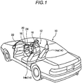
- Fig. 1 is a perspective view illustrating an example of a state where a vehicle room 12 of the vehicle 10 mounting the passenger detection device according to the present embodiment is partly viewed in a perspective manner.
- the vehicle 10 mounting the passenger detection device may be, for example, an automobile including an internal-combustion engine (not illustrated) as a driving source, that is, an internal-combustion engine automobile, an automobile including a motor (not illustrated) as a driving source, that is, an electric automobile and a fuel cell automobile, or the like.
- the vehicle 10 may be a hybrid automobile including both of them as driving sources and an automobile equipped with the other driving source.
- the vehicle 10 has the vehicle room 12 where a passenger (a driver or a fellow passenger) (not illustrated) gets in.
- a seat 14a for a driver (a driver's seat), a seat 14b for a fellow passenger (a passenger seat), a back seat (not illustrated), and the like are provided in the vehicle room 12.
- the driver and the fellow passenger are an example of a passenger.
- a steering wheel 16, a dashboard 18, and the like are provided in a state of facing the seats 14a and 14b.
- airbags for the seat 14a, and the seat 14b are stored.
- airbags for the back seat may be stored.
- the vehicle 10 may further include a side airbag stored in a door (not illustrated).
- a monitor device 20 is provided at substantially a center portion of the dashboard 18 as an information providing unit that provides various types of information items to the driver or the fellow passenger.
- the monitor device 20 includes a display device 22 including, for example, a liquid crystal display (LCD), an organic electroluminescent display (OELD), or the like.
- the monitor device 20 includes a voice output device (for example, a speaker).
- the display device 22 is covered with, for example, a transparent operation input unit such as a touch panel.
- the vehicle 10 includes an imaging device 24 that images the seats 14a and 14b or the like.
- the imaging device 24 is, for example, a charge coupled device (CCD) camera or the like. As illustrated in Fig. 1 , for example, the imaging device 24 can be provided in the monitor device 20 located substantially at the center of the dashboard 18.
- the imaging device 24 captures (images) the interior of the vehicle 10 and sequentially outputs a captured image that is image data obtained by imaging the interior of the vehicle 10 to an ECU to be described later.
- Fig. 2 is a diagram illustrating an example of an imaging range of the imaging device 24 according to the present embodiment. As illustrated in Fig. 2 , since the imaging device 24 includes the seats 14a and 14b in the imaging range, it is possible to detect a seating state of the seats 14a and 14b by one imaging device 24. Alternatively, the vehicle 10 may include a plurality of imaging devices 24, and may adopt a configuration in which the seat 14a and the seat 14b are imaged, separately.
- Fig. 3 is a side surface view illustrating an example of the seat 14b for the vehicle 10 according to the present embodiment.
- the seat 14b includes a seat cushion 2, a seat back 3, and a headrest 4.
- the seat back 3 is provided tiltably with respect to a rear end portion of the seat cushion 2.
- the headrest 4 is disposed at the upper end of the seat back 3.
- a pair of left and right lower rails 5 extending in a longitudinal direction of the vehicle 10 are provided on a floor portion F of the vehicle 10.
- An upper rail 6 that is movable relative to the lower rail 5 along the extending direction is mounted on each lower rail 5.
- a seat slide device 7 formed by each lower rail 5 and the upper rail 6 supports the seat 14b.
- the seat 14b of the present embodiment is provided with load sensors 26f and 26r below the seat cushion 2.
- the load sensors 26f and 26r are provided between the upper rail 6 and the seat cushion 2.
- the load sensors 26f and 26r are sensors for measuring (detecting) the load of the seat 14b.
- the load of the seat 14b in the present embodiment is the weight applied to the seat 14b.
- the load sensors 26f and 26r measure the weight of the baggage placed on the seat cushion 2 of the seat 14b or the weight of the passenger on the seat cushion 2 of the seat 14b as a load of the seat 14b. It is not limited to this.
- the load is applied to the seat 14b.
- the load sensors 26f and 26r measure these loads.
- the load sensors 26f and 26r may adopt a well-known strain sensor or a load cell.
- the load sensor 26f is disposed on the front side of the seat 14b, and the load sensor 26r is disposed on the rear side of the seat 14b, respectively.
- a load sensor 26 in a case where it is not necessary to particularly distinguish between the two load sensors, it is referred to as a load sensor 26.
- Fig. 4 is a plan view that an example of the seat 14b for a vehicle according to the present embodiment is illustrated.
- Fig. 4 illustrates a configuration of the seat cushion 2, the seat back 3, and the headrest 4 of a case where the seat 14b is viewed from above.
- the upper rail 6 has a pair of an upper rail 6a and an upper rail 6b.
- the upper rail 6a is positioned on the right side (the driver's seat side) of the seat 14b, and the upper rail 6b is positioned on the left side (a window side) of the seat 14b.
- the load sensors 26f and 26r are disposed between the right upper rail 6a and the seat cushion 2.
- the load of the seat 14b is measured by the two load sensors 26 disposed on the right front side and the right rear side of the seat 14b, the load of the seat 14b can be measured efficiently with a small number of the load sensors 26.
- the seat 14b (the passenger seat) is illustrated as an example.
- the seat 14a (the driver's seat) may have the same configuration.
- the disposition position of the load sensor 26 is reversed to the left and right of the seat 14b. That is, the seat 14a includes the load sensor 26 on a side (the passenger seat side) of the upper rail 6b.
- the load sensor 26 may also be disposed on the back seat (not illustrated).
- Fig. 5 is a diagram illustrating an example of a hardware configuration of a passenger detection system 100 according to the present embodiment.
- an ECU 30, a door sensor 25, the load sensor 26, an airbag 27, and the like are electrically connected to each other via an in-vehicle network 23 as an electric communication line.
- the in-vehicle network 23 is, for example, configured as a controller area network (CAN).
- the ECU 30 can control the airbag 27 or the like by sending a control signal through the in-vehicle network 23.
- the ECU 30 can receive detection results of four door sensors 25 and two load sensors 26 (26f and 26r) and the like via the in-vehicle network 23.
- the ECU 30 can receive the captured image from the imaging device 24.
- the ECU 30 is an example of the passenger detection device according to the present embodiment.
- Each of four door sensors 25 is disposed on the different doors, respectively. Each door sensor 25 detects at least whether the corresponding door is in a closed state or an open state. Each door sensor 25 may detect angle at which the door is open. In addition, the number of the door sensors 25 is not limited to four. In the present embodiment, it is assumed that the door sensor 25 can detect at least opening and closing of the door at the passenger seat.
- the ECU 30 includes, for example, a central processing unit (CPU) 31, a solid state drive (SSD) 32 (a flash memory), a read only memory (ROM) 33, a random access memory (RAM) 34, or the like.
- the CPU 31 controls the entirety of the vehicle 10.
- the CPU 31 can read out a program installed and stored in a nonvolatile storage device such as the ROM 33 and can execute an arithmetic process according to the program.
- the RAM 34 temporarily stores various data items used in the operation in the CPU 31.
- the SSD 32 is a rewritable nonvolatile storage unit, and can store data even in a case where a power supply of the ECU 30 is turned off.
- the CPU 31, the ROM 33, the RAM 34, and the like can be integrated in the same package.
- the ECU 30 may be configured to use another logic operation processor such as a digital signal processor (DSP), a logic circuit, or the like instead of the CPU 31.
- DSP digital signal processor
- a hard disk drive (HDD) may be provided instead of the SSD 32, and the SSD 32 and the HDD may be provided separately from the ECU 30.
- the passenger detection system 100 is described as an example including one ECU 30 as the passenger detection device in Fig. 5 , it is not limited to this configuration, and the passenger detection system 100 may adopt a configuration including a plurality of ECUs.
- FIG. 6 is a block diagram illustrating an example of a functional configuration of the ECU 30 according to the present embodiment.
- the ECU 30 mainly functions as an input unit 90, a detection unit 91, a threshold value changing unit 92, and a determination unit 93.
- each of configurations of the input unit 90, the detection unit 91, the threshold value changing unit 92, and the determination unit 93 is realized by executing the program stored in the ROM 33 by the CPU 31.
- These configurations may be realized by a hardware circuit.
- a storage unit 95 illustrated in Fig. 6 is configured by a storage device such as the SSD 32, for example.
- the storage unit 95 stores a load threshold value described later and a face learning database 951.
- the storage unit 95 may adopt the configuration that a passenger detection result which is determined by the determination unit 93 to be described is stored.
- the input unit 90 receives the captured image imaged by the imaging device 24 from the imaging device 24. In addition, the input unit 90 receives the load of the seat 14b which is measured by the load sensor 26, from the load sensor 26. Furthermore, the input unit 90 receives a signal indicating opening and closing of the door of the passenger seat from the door sensor 25. The input unit 90 transmits the received captured image and a signal indicating opening and closing the door to the detection unit 91. In addition, the input unit 90 transmits the received load to the determination unit 93.
- the detection unit 91 obtains the face determination degree in the captured image acquired by the input unit 90.
- the face determination degree is an index indicating a certainty of a face of the passenger.
- the face determination degree becomes higher as the face of the passenger is certainly included in the captured image.
- Fig. 7 is a diagram illustrating an example of face detection according to the present embodiment.
- the captured image illustrated in Fig. 7 includes a face of a passenger M seated on the seat 14b.
- the detection unit 91 detects a range 900 that may be the face of the passenger M from the captured image and further evaluates the degree to which the image of the range 900 appears like a face.
- the detection unit 91 may adopt a configuration in which the face determination degree of the captured image is obtained by a neural network or the like using the face learning database 951 stored in advance in the storage unit 95.
- the face learning database 951 may include data of a three-dimensional face model of a plurality of examinees (models), data of facial parts, and data of feature points.
- the detection unit 91 may adopt a configuration that generates the three-dimensional face model from a captured image using a well-known technique and compares it with data of the face learning database 951 to evaluate face likeness.
- the face determination degree is the lowest in the captured image.
- the face determination degree of the captured image is assumed to be higher.
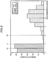
- Fig. 8 is a histogram illustrating an example of distribution of face determination degrees according to the present embodiment.
- a horizontal axis represents the face determination degree and a vertical axis represents a normalization frequency obtained by normalizing the number of samples (degrees) at each determination degree.
- Fig. 8 illustrates the output result of the detection unit 91 in a case where the detection unit 91 obtains the number of the face determination degree for the captured image obtained by imaging a face and the captured image obtained by imaging an image other than the face.
- the face determination degree in the captured image obtained by imaging the face becomes "1" or more.
- the detection unit 91 transmits the face determination degree to the threshold value changing unit 92.
- the face determination degree "1" is set as a reference value a for dividing whether or not a face is included in the captured image, but this value is an example, and is not limited thereto.
- the reference value a in the present embodiment is an example of a predetermined reference.
- the face determination degree in the present embodiment indicates values of 0 to 6. However, it is not limited thereto.
- the detection unit 91 may indicate the face determination degree by a rank such as A, B, C, or the like, or may be simply classified as "high” or "low”.
- the determination unit 93 determines that the passenger M is seated on the seat 14b.
- the determination unit 93 may adopt a configuration in which the determination result of the presence or absence of passenger M (a passenger detection result) is stored in the storage unit 95.
- the determination unit 93 may adopt a configuration of outputting the determination result to an external device (not illustrated).
- the threshold value changing unit 92 changes the threshold value of the load according to the face determination degree acquired from the detection unit 91. Specifically, the threshold value changing unit 92 changes the threshold value such that the threshold value becomes smaller as the face determination degree acquired from the detection unit 91 is higher. For example, it is assumed that the threshold value of the load stored in the storage unit 95 is an initial value matched with the case where the face determination degree is the reference value a illustrated in Fig. 8 . In a case where the face determination degree is equal to or more than the reference value a, the threshold value changing unit 92 sets the threshold value smaller than the initial value. As described above, in a case where the face determination degree is high, the threshold value changing unit 92 changes the threshold value, so that the determination unit 93 determines that the passenger M is seated on the seat 14b even with a smaller load.
- the threshold value changing unit 92 sets the threshold value to be more than the initial value. As described above, in a case where the face determination degree is low, the threshold value changing unit 92 changes the threshold value, so that the determination unit 93 determines that the passenger M is not seated on the seat 14b even with a larger load. The threshold value changing unit 92 transmits the changed threshold value to the determination unit 93.
- the initial value of the threshold value is the threshold value of the load of a case where the face determination degree is the reference value a, but it is not limited thereto.
- a configuration in which the initial value of the threshold value is set high according to a case where the face determination degree is low and the threshold value changing unit 92 changes the threshold value to a smaller value as the face determination degree is higher, may be adopted.
- FIG. 9 is a flowchart illustrating an example of a procedure of a passenger detection process by the ECU 30 according to the present embodiment.
- a process of the flowchart starts, for example, in a case where the input unit 90 receives the signal indicating opening and closing the door from the door sensor 25. Alternatively, the process of this flowchart may be started at certain time intervals in a case where an ignition power supply of the vehicle 10 is turned on.
- the input unit 90 receives the captured image from the imaging device 24 (S1). The input unit 90 transmits the received captured image to the detection unit 91.
- the detection unit 91 obtains the face determination degree in the received captured image (S2).
- the detection unit 91 transmits the obtained face determination degree to the threshold value changing unit 92.
- the threshold value changing unit 92 reduces the threshold value of the load as the face determination degree acquired from the detection unit 91 becomes higher (S3).
- the threshold value changing unit 92 transmits the changed threshold value to the determination unit 93.
- the input unit 90 receives a measured value of the load from the load sensor 26 (S4).
- the input unit 90 transmits the received measured value of the load to the determination unit 93.
- the determination unit 93 acquires the value of the load received by the input unit 90 and the threshold value of the load which is changed by the threshold value changing unit 92. In a case where the received value of the load is equal to or more than the threshold value of the load ("Yes" in S5), the determination unit 93 determines that the passenger M is seated on the seat 14b, and determines as "there is a passenger" (S6).
- the determination unit 93 determines that there is no passenger M seated on the seat 14b, and determines as "there is no passenger” (S7).
- the determination unit 93 determines the presence or absence of the passenger M, a process of the flowchart ends.
- the ECU 30 controls switching of the mode as to whether or not to deploy the airbag 27 in a case where an impact is detected, based on the passenger detection result determined by the determination unit 93. For example, in a case where the latest determination result is "there is a passenger", the ECU 30 sets the airbag 27 in a deployment mode and in a case where the latest determination result is "there is no passenger", the ECU 30 sets the airbag 27 in the non-deployment mode.
- the detection unit 91 obtains the face determination degree indicating the certainty of the face of the passenger M in the captured image from the captured image in which the interior of the vehicle 10 is imaged and the threshold value changing unit 92 changes the threshold value of the load according to the face determination degree.
- the determination unit 93 determines that the passenger M is seated on the seat 14b.
- the ECU 30 in the present embodiment it is possible to suppress erroneous detection due to a load of a baggage or the like and distinguish the presence or absence of the passenger M who is seated on the seat 14b of the vehicle 10 with high accuracy.
- the threshold value changing unit 92 changes the threshold value of the load smaller as the face determination degree in the captured image is higher, according to the ECU 30 in the present embodiment, even in a case where a passenger having a light body weight is seated on the seat, it is possible to detect the passenger M with high accuracy. In other words, in a case where the face determination degree in the captured image is low, since the threshold value of the load becomes large, according to the ECU 30 in the present embodiment, it is possible to suppress the erroneous detection as the passenger even in a case where a baggage having the same degree of weight as the weight of a person is placed on the seat 14b.
- the ECU 30 not only determines the face determination degree in the captured image but also makes a determination based on the load. Therefore, the reliability of passenger detection can be maintained irrespective of imaging conditions. For example, even in a case where it is difficult to precisely determine the face determination degree because the captured image is unclear due to fogging, dirt of a lens of the imaging device 24, backlight, or the like, it is possible to detect that the passenger M is seated on the seat by making a determination based on the load.
- the ECU 30 even in a case where the face of the passenger M on the back seat appears in the captured image, or even in a case where the face determination degree of the captured image is high depending on a pattern of the seat 14b, it is possible to suppress erroneous detection by performing the combined determination by the load.
- the determination unit 93 of the present embodiment can detects the passenger M with high accuracy, switching of the mode whether the airbag 27 is deployed can be controlled with higher accuracy. For example, even in a case where the passenger M having a light body weight is seated on the seat, it is possible to deploy the airbag 27 by the ECU 30. In addition, in a case where the baggage is placed on the seat 14b, the ECU 30 can prevent the airbag 27 being deployed when the baggage is erroneously detected as the passenger M. As described above, according to the ECU 30 in the present embodiment, it is possible to provide the deployment control of the airbag 27 with high safety by detecting the passenger M with high accuracy.
- the ECU 30 may adopt a configuration that controls whether or not to issue an alarm according to the passenger detection result.
- the ECU 30 may adopt a configuration that issues the alarm or the like to urge the seat belt to be worn in a case where the latest determination result is "there is a passenger" and the seat belt is not worn.
- the ECU 30 can issue an alarm prompting the user to wear the seat belt even in a case where the passenger M having a light body weight is seated on the seat.
- the ECU 30 can prevent from issuing the alarm to urge the seat belt to be worn when the baggage is erroneously detected as the passenger M.
- the example in which the passenger M sitting on the seat 14b (the passenger seat) is detected is described.
- the passenger detection device of the present embodiment can also be applied to the seat 14a (the driver's seat) and the back seat.
- two load sensors 26 are provided on the seat 14b.
- a configuration in which four load sensors 26 are disposed on the seat 14b may be adopted.
- the configuration in which the threshold value changing unit 92 changes the threshold value of the load according to the face determination degree is adopted.
- the ECU 30 may adopt a configuration of adding to the measured value of the load as the face determination degree is higher.
- the threshold value of the load is changed according to the face determination degree regardless of a magnitude of the difference between the face determination degree and the reference value a in the captured image.
- the threshold value of the load is not changed.
- the threshold value changing unit 92 of the present embodiment does not change the threshold value of the load. Specifically, in a case where the face determination degree is within a range that the face determination degree is equal to or more than a first reference value b1 illustrated in Fig. 8 and less than a second reference value b2, the threshold value changing unit 92 of the present embodiment does not change the threshold value of the load. In other words, in a case where the face determination degree is less than the first reference value b1 or equal to or more than the second reference value b2, the threshold value changing unit 92 of the present embodiment sets the threshold value of the load smaller as the face determination degree is higher.
- the reference value a of the face determination degree is a boundary between whether or not a face is included in the captured image.
- the captured image contains the face more reliably.
- the face determination degree is lower than the reference value a, the face is not included more reliably in the captured image. That is, as the difference between the face determination degree of the captured image and the reference value a increases, the reliability of the determination as to whether or not the face is included in the captured image increases.
- the threshold value changing unit 92 determines the presence or absence of the passenger M with higher accuracy by changing the threshold value of the load only in a case where the captured image contains a face more reliably and a case where the face is not included more reliably in the captured image.
- a range that is equal to or more than the first reference value b1 and less than the second reference value b2 illustrated in Fig. 8 is set as a predetermined range.
- the face determination degree of the first reference value b1 is lower than that of the reference value a.
- the face determination degree of the second reference value b2 is higher than that of the reference value a.
- the face determination degree of the reference value a is set to "1”
- the face determination degree of the first reference value b1 is set to "0.5”
- the face determination degree of the second reference value b2 is set to "2".
- the threshold value changing unit 92 changes the threshold value of the load.
- the value of the reference values in the present embodiment is an example, and it is not limited thereto.
- Fig. 10 is a flowchart illustrating an example of a procedure of a passenger detection process by the ECU 30 according to the present embodiment.
- a start condition of the flowchart is the same as that of Embodiment 1.
- processes of receiving of the captured image of S1 and obtaining the face determination degree of S2 are the same as the processes of Embodiment 1 illustrated in Fig. 9 .
- the threshold value changing unit 92 of the present embodiment does not change the threshold value of the load.
- the threshold value changing unit 92 of the present embodiment reduces the threshold value of the load as the face determination degree becomes higher (S3).
- Processes from the receiving of the measured value of the load of S4 to determining of the presence or absence of the passenger M of S6 and S7 are the same processes as the processes of Embodiment 1 illustrated in Fig. 9 .
- the ECU 30 in the present embodiment does not change the threshold value of the load. That is, in a case where the face determination degree takes a value near the boundary as to whether or not a face is included in the captured image, the ECU 30 of the present embodiment does not adopt the result of the face determination degree. Accordingly, according to the ECU 30 of the present embodiment, it is possible to determine the presence or absence of the passenger M with higher accuracy by performing the passenger detection based on only the highly reliable face determination degree.
- the timing of the face determination matches the timing at which the load of the seat increases.
- the time at which the imaging device 24 images the face of the passenger M and the timing at which the load of the seat 14b increases are matched with each other.
- the presence or absence of the passenger M is determined with higher accuracy by determining the presence or absence of such a timing matching.
- the timing of the face determination is set to an imaging time of the captured image in a case where the face determination of the captured image is equal to or more than a predetermined value.
- the timing when the load of the seat increases is set to a time when the load increases in a certain amount or more. Increasing in a certain amount or more means, for example, that the load increases by 10 kg or more.
- matching the timing means that a time difference between the timing of the face determination and the timing when the load of the seat increases is within a predetermined time.
- Fig. 11 is a block diagram illustrating an example of a functional configuration of the ECU 30 according to the present embodiment.
- the ECU 30 mainly functions as an input unit 1090, a detection unit 1091, the threshold value changing unit 92, a determination unit 1093, and a timing determination unit 94.
- each of configurations of the input unit 1090, the detection unit 1091, the threshold value changing unit 92, the determination unit 1093, and the timing determination unit 94 is realized by executing the program stored in the ROM 33 by the CPU 31.
- These configurations may be realized by a hardware circuit.
- the threshold value changing unit 92 is the same as that of Embodiment 1 illustrated in Fig. 6 .
- a storage unit 1095 illustrated in Fig. 11 is configured by a storage device such as the SSD 32, for example.
- the storage unit 1095 further stores a load measuring database 952.
- the input unit 1090 has the same function as that of Embodiment 1 and transmits the received captured image and the time when the captured image is received, that is, the imaging time of the captured image in association with each other to the timing determination unit 94.
- the input unit 1090 stores load measuring data by associating the received load and the time when the load is received, that is, the measuring time of the load with each other to the load measuring database 952 of the storage unit 1095.
- the input unit 1090 may adopt a configuration acquiring the time from a time circuit (not illustrated) in the ECU 30.
- the input unit 1090 may adopt a configuration acquiring a time from an external device (not illustrated).
- the timing determination unit 94 determines that the timings are matched. In other words, in a case where the difference between the time when the captured image in which the face determination degree is equal to or more than the predetermined reference is received and the time when the load of the seat increases in a certain amount or more is within the predetermined time, the timing determination unit 94 determines that the timings are matched. For example, in a case where the time difference between the timing of the face determination and the timing when the load of the seat increases is within in ⁇ 5 seconds, the timing determination unit 94 determines that the timings are matched.
- the predetermined reference of the face determination degree in the present embodiment is set, for example, to the reference value a illustrated in Fig. 8 .
- the second reference value b2 illustrated in Fig. 8 may be set as a predetermined reference.
- the timing determination unit 94 acquires the captured image and the imaging time from the input unit 1090. In addition, in a case where, in the captured image, the face determination degree obtained by the detection unit 1091 is equal to or more than the reference value a, the timing determination unit 94 searches load measuring data within the past 5 seconds from the imaging time of the captured image from the load measuring database 952 and calculates the increasing amount of the load. In a case where the increasing amount of the load within the past 5 seconds from the imaging time of the captured image is 10 kg or more, the timing determination unit 94 determines that the timing of face determination matches the timing when the load of the seat increases.
- the timing determination unit 94 repeats acquisition of the load measuring data and calculation of the increasing amount of the load until 5 seconds have elapsed from the imaging time of the captured image. In a case where the load increases by 10 kg or more from the imaging time of the captured image by 5 seconds, the timing determination unit 94 determines that the timing of the face determination matches the timing of the increase in the load of the seat.
- the timing determination unit 94 determines that timing of the face determination does not match the timing when the load of the seat increases.
- the timing determination unit 94 determines that there is no face detection.
- the timing determination unit 94 stores the timing determination result to the storage unit 1095, for example.
- the timing determination unit 94 may transmit the timing determination result to the determination unit 1093.
- the detection unit 1091 has the same function as that of Embodiment 1. In addition, the detection unit 1091 of the present embodiment further transmits the obtained face determination degree in the timing determination process to the timing determination unit 94. In addition, the detection unit 1091 transmits the obtained face determination degree in the passenger detection process to the threshold value changing unit 92.
- the timing determination process starts in a case where the input unit 1090 receives the signal indicating that the door is in an open state from the door sensor 25, for example.
- the passenger detection process starts after ending the timing determination process.
- the detection unit 1091 may adopt the configuration that the obtained face determination degree is transmitted to the timing determination unit 94.
- the detection unit 1091 may adopt a configuration of transmitting the obtained face determination degree in the passenger detection process to the threshold value changing unit 92.
- the determination unit 1093 determines that the passenger M is seated on the seat 14b. That is, in a case where the detected load is equal to or more than the threshold value, and a difference between the time when the captured image in which the face determination degree is equal to or more than the predetermined reference is acquired and a time when the load increases in a certain amount or more is within a predetermined time, the determination unit 1093 determines that the passenger M is seated on the seat 14b.
- the determination unit 1093 may adopt a configuration that the determination result (the passenger detection result) of the presence or absence of the passenger M is stored in the storage unit 1095. Alternatively, the determination unit 1093 may adopt a configuration of outputting the determination result to an external device (not illustrated).
- timing determination unit 94 determines the timing based on the face determination degree and the increasing amount of the load, it is possible to detect that the passenger M got into the seat 14b. On the other hand, whether the passenger M continues to be seated on the seat 14b or not can be determined by the determination unit 1093 periodically comparing the load with the threshold value.
- Fig. 12 is a flowchart illustrating an example of procedure of a timing determination process by the ECU 30 according to the present embodiment.
- a process of the flowchart starts, for example, in a case where the input unit 1090 receives the signal indicating an opening state of the door from the door sensor 25. Alternatively, the process of this flowchart may be started in a case where the ignition power supply of the vehicle 10 is turned on.
- the input unit 1090 receives the captured image from the imaging device 24 (S21). The input unit 1090 transmits the received captured image and the imaging time of the captured image in association with each other to the detection unit 1091. In addition, the input unit 1090 receives the measured value of the load from the load sensor 26 (S22). In addition, the input unit 1090 stores load measuring data associating the received load and the load measuring time of the load with each other to the load measuring database 952 of the storage unit 1095. The input unit 1090 receives the measured value of the load at certain time intervals, for example, at intervals of one second until the process of the flowchart ends, and stores the load measuring data associating the received load with the measuring time of the load to the load measuring database 952 of the storage unit 1095.
- the detection unit 1091 obtains the face determination degree in the received captured image (S23).
- the detection unit 1091 transmits the face determination degree of the captured image and the imaging time to the timing determination unit 94.
- the timing determination unit 94 compares the face determination degree acquired from the detection unit 1091 with the reference value a (S24). In a case where it is determined that the face determination degree is equal to or more than the reference value a ("Yes" in S24), the timing determination unit 94 searches the load measuring data within the past 5 seconds from the imaging time of the captured image from the load measuring database 952. In a case where the increasing amount of the load within the past 5 seconds is 10 kg or more ("Yes" in S25), the timing determination unit 94 determines that the timing of the face determination and the timing of increasing the load of the seat are matched to each other ("timing match") (S26).
- the timing determination unit 94 determines whether 5 seconds have elapsed since the imaging time of the captured image (S27). In a case where the timing determination unit 94 determines that 5 seconds does not have elapsed since the imaging time of the captured image ("No" in S27), the timing determination unit 94 repeats processes of S25 and S27 until 5 seconds have elapsed since the imaging time of the captured image. Meanwhile, the input unit 1090 receives the measured value of the load at a certain time interval, and a process of S22 in which the load measuring data correlating the received load and the measuring time of the load is stored in the load measuring database 952 of the storage unit 1095 continues. The timing determination unit 94 repeats the processes of S25 and S27 to calculate an increasing amount of the newly received load.
- the timing determination unit 94 determines that the timing of the face determination does not match the timing when the load of the seat increases ("timing mismatch") (S28).
- the timing determination unit 94 and the input unit 1090 repeat processes of S21 to S24 and S29 until a certain time has elapsed since the start of the process of the flowchart ("No" in S29). For example, it takes some time for the passenger M to board the vehicle 10 and turn the face of the passenger M toward the imaging device 24 after the door of the vehicle 10 is in the open state, in some cases.
- the timing determination unit 94, the input unit 1090, and the detection unit 1091 repeat the processes for a certain time, it can determine the timing even when it takes the time from the start of the process until the imaging of the face of the passenger M.
- the timing determination unit 94 determines that "there is no face detection" (S30).
- the timing determination unit 94 stores the determination result to the storage unit 1095, for example.
- the timing determination unit 94 may transmit the timing determination result to the determination unit 1093.
- the process ends in a case where a certain time has elapsed since start of the process.
- the timing determination unit 94, the input unit 1090, and the detection unit 1091 may adopt a configuration of repeating the processes of S21 to S25 and S27 until the determination result of "timing match” or "timing mismatch” is obtained.
- the determination result is "timing mismatch” or "there is no face detection”
- a configuration in which the processing of the flowchart starts again may be adopted.
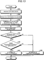
- Fig. 13 is a flowchart illustrating an example of procedure of a passenger detection process by the ECU 30 according to the present embodiment.
- a process of the flowchart starts in a case where the timing determination result is stored in a storage unit 1095 by the timing determination unit 94.
- the process of this flowchart may be started at certain time intervals in a case where an ignition power supply is turned on.
- the process of receiving of the captured image in S41 and the process for comparing the received loads and the threshold value in S45 are the same as the processes of S1 to S5 of Embodiment 1 illustrated in Fig. 9 .
- the determination unit 1093 of the present embodiment further determines whether the timing determination result is in "timing match” (S46).
- the determination unit 1093 may acquire the timing determination result stored in the storage unit 1095 and may acquire the determination result from the timing determination unit 94 when ending the timing determination process of Fig. 12 .
- the determination unit 1093 determines that the passenger M is seated on the seat 14b and determines as "there is passenger” (S47).
- the determination unit 1093 determines that there is no passenger M seated on the seat 14b and determined as "there is no passenger” (S48). In addition, similar to Embodiment 1, in a case where the received load is less than the threshold value ("No" in S45), the determination unit 1093 determines that there is no passenger M seated on the seat 14b, and determines as "there is no passenger” (S48). When the determination unit 1093 determines the presence or absence of the passenger M, a process of the flowchart ends.
- the passenger detection process of Fig. 13 may be executed after the timing determination process, or may be periodically executed in a case where the ignition power supply of the vehicle 10 is in an ON state.
- the determination unit 1093 detects that the load is equal to or less than the threshold value, for example, in a case where the passenger M gets off the seat 14b after it is determined as "there is a passenger", and it is determined that "there is no passenger".
- the determination unit 1093 of the present embodiment determines that the passenger M is seated on the seat 14b. Accordingly, in the determination unit 1093 according to the present embodiment, it is possible to suppress the erroneous detection by setting the both conditions that it is determined whether the load is equal to or more than the threshold value and it is determined whether a timing of a variation of the load matches a timing of a face determination, whereby determining the presence or absence of the passenger with higher accuracy.
- the face determination degree in the captured image is not equal to or more than the reference value a, it is possible to suppress the erroneous detection of a baggage as the passenger M.
- the face determination degree of the captured image is high depending on a pattern of the seat 14b or even in a case where the face of the passenger on the back seat appears in the captured image, it does not match the timing of the increase of the load of the seat 14b, it is possible to suppress erroneous detection.
- the determination unit 1093 determines that the passenger M is seated on the seat 14b.
- the ECU 30 may adopt a configuration that it is determined that the passenger M is seated on the seat 14b and it is determined as "there is a passenger". In a case of adopting the configuration, since the presence or absence of the passenger M is detected with less processes, it is possible to reduce the process load.
- the ECU 30 does not necessarily change the load threshold value according to the face determination degree.
- the ECU 30 may adopt a configuration that it is determined that the passenger M is seated on the seat 14b in a case where the received load is equal to or more than the threshold value of the load stored in the storage unit 1095 and it is determined as "there is a passenger".
- the increasing amount of the load within 5 seconds before and after is equal to or more than 10 kg with reference to a case where the face determination degree is equal to or more than the reference value a.
- the face determination degree is equal to or more than the reference value a within the 5 seconds before and after the time (which is the reference) when the load is increased by 10 kg or more.
- the reference of increasing the load more than a certain value is set to 10 kg, but this is an example, and the reference of the increasing amount of the load is not limited thereto.
- the time difference for determining that the timings match to each other by the timing determination unit 94 is ⁇ 5 seconds, but this is only an example, and the reference of the time difference is not limited thereto.
- the configuration that the input unit 1090 receives the measured value of the load is adopted.
- the input unit 1090 may adopt a configuration that the measured value of the load is received at a certain time, for example, every 1 second, and the load measuring data is continuously stored in the storage unit 1095 regardless of the start of the timing determination process.
- timing mismatch and “there is no face detection” are distinguished, but it is not limited thereto.
- the timing determination unit 94 may adopt a configuration for simply determining whether the timings match.
- the passenger detection process is executed after the timing determination process.
- the timing determination process may be incorporated in the passenger detection process.
- the presence or absence of the passenger M is determined by the load of the seat 14b.
- the load due to the passenger and the load due to the baggage are also measured.
- the ECU 30 of the present embodiment estimates the load due to the passenger with good accuracy by subtracting the load in the empty seat state from the load measuring value and performs the passenger detection with higher accuracy.
- the empty seat state in the present embodiment means a state where the passenger M is not seated on the seat 14b, in other words, in an unmanned state.
- the empty seat state includes a state where the baggage or the like is placed on the seat 14b and a state in which a baggage is present in a pocket or a hook on the back surface of the seat 14b.
- Fig. 14 is a block diagram illustrating an example of a functional configuration of the ECU 30 according to the present embodiment.
- the ECU 30 mainly functions as an input unit 2090, a detection unit 2091, the threshold value changing unit 92, a determination unit 2093, a storage unit 2095, a correction value setting unit 96, and a load correction unit 97.
- each of configurations of the input unit 2090, the detection unit 2091, the threshold value changing unit 92, the determination unit 2093, the correction value setting unit 96, and the load correction unit 97 is realized by executing the program stored in the ROM 33 by the CPU 31. These configurations may be realized by a hardware circuit.
- the threshold value changing unit 92 is the same as that of Embodiment 1 illustrated in Fig. 6 .
- the storage unit 2095 illustrated in Fig. 14 is configured by a storage device such as the SSD 32, for example.
- the storage unit 2095 further stores a load correction value to be described.
- the correction value setting unit 96 sets the load of the seat 14b in the empty seat state as the load correction value. Specifically, in a case where the face determination degree of the captured image obtained by the the detection unit 2091 is less than a predetermined reference, the correction value setting unit 96 determines that the load received by the input unit 2090 is a load in the empty seat state.
- the predetermined reference of the face determination degree in the present embodiment is set, for example, to the reference value a illustrated in Fig. 8 .
- the second reference value b2 illustrated in Fig. 8 may be set as a predetermined reference.
- the correction value setting unit 96 stores the load of the seat 14b in the empty seat state to the storage unit 2095 as the load correction value.
- the baggage stored in the pocket of the seat 14b is not always the same weight at all times. Therefore, in the ECU 30 of the present embodiment, the load detection process in the empty seat state described below is periodically executed. Therefore, the correction value setting unit 96 detects the load of the latest empty seat state and updates the load correction value.
- the load correction unit 97 subtracts the load correction value from the load received by the input unit 2090 to correct the load. For example, in a case where 3 kg of the baggage is stored in advance in the pocket or the like of the back surface of the seat 14b, the load in the empty seat state is 3 kg. In the passenger detection process, in a case where the load received by the input unit 2090 is 40 kg, the load correction unit 97 subtracts 3 kg from the load and corrects the load to 37 kg. In other words, by subtracting the weight in the empty seat state from the load received by the input unit 2090, the load correction unit 97 estimates the load due to the weight of the passenger M. The load correction unit 97 transmits the weight after correcting to the determination unit 2093.
- the input unit 2090 has the same function as that of Embodiment 1, and in the load detection process of the empty seat state, the input unit 2090 transmits the received load to the correction value setting unit 96.
- the detection unit 2091 has the same function as that of Embodiment 1. In the load detection process in the empty seat state, the detection unit 2091 of the present embodiment further transmits the obtained face determination degree to the correction value setting unit 96. In addition, in the passenger detection process, the detection unit 2091 transmits the obtained face determination degree to the threshold value changing unit 92.
- Whether one of the load detection process in the empty seat state and the passenger detection process is executed may be distinguished by the time, for example.
- the load detection process in the empty seat state may be started at a certain time interval such as every hour.
- a configuration in which the load detection process in the empty seat state may be executed at a certain time interval even in a state where the ignition power supply is turned off may be adopted.
- the ECU 30 of the present embodiment may adopt the configuration that the power supply is supplied from a battery (not illustrated).
- the passenger detection process is started in a case where the signal indicating the opening and closing the door is received by the input unit 2090, for example.
- the passenger detection process may be executed at a certain time interval in a case where an ignition power supply of the vehicle 10 is turned on. The execution interval of the passenger detection process is assumed to be shorter than the load detection process in the empty seat state.
- the determination unit 2093 acquires the load after correcting from the load correction unit 97 and acquires the threshold value after changing from the threshold value changing unit 92. In a case where the load corrected by the load correction unit 97 is equal to or more than the threshold value, the determination unit 2093 determines that the passenger M is seated on the seat 14b.
- FIG. 15 is a flowchart illustrating an example of a procedure of a load detection process in the empty seat state by the ECU 30 according to the present embodiment.
- the processes of the flowchart are started at a certain time interval such as every hour, for example.
- the input unit 2090 receives the captured image from the imaging device 24 (S51). The input unit 2090 transmits the received captured image to the detection unit 2091. In addition, the input unit 2090 receives the measured value of the load from the load sensor 26 (S52). The input unit 2090 transmits the received load to the correction value setting unit 96.
- the detection unit 2091 obtains the face determination degree in the received captured image (S53). The detection unit 2091 transmits the obtained face determination degree to the correction value setting unit 96.
- the correction value setting unit 96 determines the load received by the input unit 2090 as the load in the empty seat state.
- the correction value setting unit 96 stores the load in the empty seat state to the storage unit 2095 as the load correction value (S55).
- the correction value setting unit 96 may adopt the configuration of overwriting with the latest load correction value.
- the correction value setting unit 96 determines that the load received by the input unit 2090 is not the load in the empty seat state and ends the process.
- Fig. 16 is a flowchart illustrating an example of procedure of a passenger detection process by the ECU 30 according to the present embodiment.
- a process of the flowchart starts, for example, in a case where the input unit 2090 receives the signal indicating opening and closing the door. Alternatively, the process of this flowchart may be executed at a certain time interval in a case where an ignition power supply of the vehicle 10 is turned on.
- Processes of receiving of the captured image in S61 and changing the threshold value of the load of S63 are the same as the processes S1 to S3 of Embodiment 1 illustrated in Fig. 9 .
- the input unit 2090 receives a measured value of the load from the load sensor 26 (S64). The input unit 2090 transmits the received measured value of the load to the load correction unit 97.
- the load correction unit 97 subtracts the load correction value stored in the storage unit 2095 from the load received by the input unit 2090 (S65).
- the load correction unit 97 transmits the load after subtracting to the determination unit 2093.
- the determination unit 2093 acquires the load which is subtracted by the load correction unit 97 and the threshold value of the load which is changed by the threshold value changing unit 92. In a case where the load after subtracting is equal to or more than the threshold value ("Yes" in S66), the determination unit 2093 determines whether the passenger M is seated on the seat 14b and determines as "there is a passenger" (S67).
- the determination unit 2093 determines that there is no passenger M seated on the seat 14b, and determines as "there is no passenger" (S68). When the determination unit 2093 determines the presence or absence of the passenger M, the process of the flowchart ends.
- the correction value setting unit 96 stores the load measured by the load sensor 26 as a load correction value to the storage unit 2095 and the load correction unit 97 corrects the load by the load correction value. Accordingly, according to the ECU 30 of the present embodiment, it is possible to exclude the load due to the baggage from the detected load to detect the load due to the weight of the passenger M with high accuracy. Therefore, according to the ECU 30 of the present embodiment, it is possible to distinguish the presence or absence of the passenger M seated on the seat 14b of the vehicle 10.
- the load detection process in the empty seat state is performed in advance before the passenger detection process to calculate the load correction value.
- the load received in the passenger detection process may be stored in the storage unit 2095 as the load correction value and the stored load may be used for correcting the load in the next and following passenger detection process.
- the load detection process in the empty seat state is started, for example, at intervals of one hour.
- the execution interval of the process is not limited thereto.
- the execution interval of the process may be every other day or the like.
- the face determination degree in the captured image is used for both the detection in the empty seat state and the change in the load threshold value.
- the ECU 30 of the present embodiment may adopt the configuration that the ECU 30 does not change the threshold value of the load.
Landscapes
- Engineering & Computer Science (AREA)
- Mechanical Engineering (AREA)
- Aviation & Aerospace Engineering (AREA)
- Transportation (AREA)
- Computer Vision & Pattern Recognition (AREA)
- Physics & Mathematics (AREA)
- Multimedia (AREA)
- Theoretical Computer Science (AREA)
- General Physics & Mathematics (AREA)
- Health & Medical Sciences (AREA)
- General Health & Medical Sciences (AREA)
- Oral & Maxillofacial Surgery (AREA)
- Human Computer Interaction (AREA)
- Image Analysis (AREA)
- Image Processing (AREA)
- Seats For Vehicles (AREA)
- Fittings On The Vehicle Exterior For Carrying Loads, And Devices For Holding Or Mounting Articles (AREA)
Abstract
Description
- This disclosure relates to a passenger detection device and a passenger detection program.
- In the related art, a passenger detection device that detects a passenger seated on a seat with a load sensor provided on a seat of a vehicle is known. In addition, a passenger detection device that detects a passenger by imaging inside of a vehicle with a camera is also known.
- Examples of related art include
JP 9-150662A JP 2007-198929A JP 2006-205844A - However, as described above, the passenger detection device that detects the passenger by the load may erroneously determine that the passenger is seated due to a load of a baggage or the like placed on the seat. It is difficult to determine presence or absence of a passenger who is seated on the seat with high accuracy. In addition, in the passenger detection device that detects the passenger from a captured image of the camera, it is difficult to determine the presence or absence of the passenger with high accuracy depending on an imaging condition, in some cases.
- Thus, a need exists for a passenger detection device and a passenger detection program capable of distinguishing presence or absence of the passenger who is seated on a seat of a vehicle with high accuracy, for example.
- A passenger detection device according to an aspect of this disclosure includes, as an example, an input unit that is configured to receive a captured image of an interior space of a vehicle imaged by an imaging device and a load measured by a load sensor provided on a seat provided in the interior space of the vehicle, a determination unit that is configured to determine that a passenger is seated on the seat, in a case where the load is equal to or more than a predetermined threshold value, a detection unit that is configured to obtain a face determination degree indicating a certainty of a face of the passenger in the captured image from the captured image, and a threshold value changing unit that is configured to change the threshold value according to the face determination degree. Therefore, as an example, according to the passenger detection device, it is possible to suppress erroneous detection due to a load of a baggage or the like and distinguish the presence or absence of the passenger who is seated on the seat of the vehicle with high accuracy.
- In the passenger detection device, as an example, the threshold value changing unit is configured to change the threshold value to a smaller value as the face determination degree is high. Therefore, as an example, according to the passenger detection device, even in a case where a passenger having a light body weight is seated on the seat, it is possible to detect the passenger with high accuracy. In addition, as another example, according to the passenger detection device, even in a case where a baggage having the same degree of weight as the weight of a person is placed on the seat, it is possible to suppress the erroneous detection as the passenger.
- In the passenger detection device, as an example, in a case where a difference between the face determination degree and a predetermined reference is within a predetermined range, the threshold value changing unit does not change the threshold value. Therefore, as an example, according to the passenger detection device, it is possible to determine the presence or absence of the passenger with high accuracy only using the highly reliable face determination degree.
- In the passenger detection device, as an example, in a case where the detected load is equal to or more than the threshold value, and a difference between a time at which the captured image in which the face determination degree is equal to or more than a predetermined reference is acquired and a time at which the load increases to a certain amount or more is within a predetermined time, the determination unit determines that the passenger is seated on the seat. Therefore, as an example, according to the passenger detection device, it is possible to suppress the erroneous detection by setting the both conditions that it is determined whether the load is equal to or more than the threshold value and it is determined whether a timing of a variation of the load matches a timing of a face determination, whereby determining the presence or absence of the passenger with higher accuracy.
- As an example, the passenger detection device further includes a correction value setting unit that in a case where the face determination degree of the captured image is lower than a predetermined reference, stores the detected load to a storage unit as a load correction value, and a load correction unit that corrects a value of the load by subtracting a load correction value stored in the storage unit from the detected load. In addition, in the passenger detection device, as an example, in a case where the load after corrected by the load correction unit is equal to or more than the threshold value, the determination unit determines that the passenger is seated on the seat. Therefore, as an example, according to the passenger detection device, it is possible to detect the load due to the weight of the passenger with high accuracy by excluding the load due to the baggage from the received load. Accordingly, as an example, according to the passenger detection device, it is possible to determine the presence or absence of the passenger with higher accuracy.
- A passenger detection program according to an aspect of this disclosure causes, as an example, a computer to execute steps of: receiving a captured image of an interior space of a vehicle imaged by an imaging device and a load measured by a load sensor provided on a seat provided in the interior space of the vehicle; determining that a passenger is seated on the seat, in a case where the load is equal to or more than a predetermined threshold value; obtaining a face determination degree indicating a certainty of a face of the passenger in the captured image, from the captured image; and changing the threshold value according to the face determination degree.
- The foregoing and additional features and characteristics of this disclosure will become more apparent from the following detailed description considered with the reference to the accompanying drawings, wherein:
-
Fig. 1 is a perspective view illustrating an example of a state where a vehicle room of a vehicle mounting a passenger detection device according toEmbodiment 1 is partly viewed in a perspective manner; -
Fig. 2 is a diagram illustrating an example of an imaging range of an imaging device according toEmbodiment 1; -
Fig. 3 is a side surface view illustrating an example of a seat for a vehicle according toEmbodiment 1; -
Fig. 4 is a plan view illustrating an example of the seat for a vehicle according to Embodiment; -
Fig. 5 is a diagram illustrating an example of a hardware configuration of a passenger detection system according toEmbodiment 1; -
Fig. 6 is a block diagram illustrating an example of a functional configuration of an ECU according toEmbodiment 1; -
Fig. 7 is a diagram illustrating an example of face detection according toEmbodiment 1; -
Fig. 8 is a histogram illustrating an example of distribution of face determination degrees according toEmbodiment 1; -
Fig. 9 is a flowchart illustrating an example of a procedure of a passenger detection process by the ECU according toEmbodiment 1; -
Fig. 10 is a flowchart illustrating an example of a procedure of a passenger detection process by an ECU according toEmbodiment 2; -
Fig. 11 is a block diagram illustrating an example of a functional configuration of an ECU according toEmbodiment 3; -
Fig. 12 is a flowchart illustrating an example of procedure of a timing determination process by the ECU according toEmbodiment 3; -
Fig. 13 is a flowchart illustrating an example of a procedure of a passenger detection process by the ECU according toEmbodiment 3; -
Fig. 14 is a block diagram illustrating an example of a functional configuration of an ECU according toEmbodiment 4; -
Fig. 15 is a flowchart illustrating an example of a procedure of a load detection process in an empty seat state by the ECU according toEmbodiment 4; and -
Fig. 16 is a flowchart illustrating an example of a procedure of a passenger detection process by the ECU according toEmbodiment 4. - Hereinafter, an example that a passenger detection device of the present embodiment is mounted on a
vehicle 10 will be described. -
Fig. 1 is a perspective view illustrating an example of a state where avehicle room 12 of thevehicle 10 mounting the passenger detection device according to the present embodiment is partly viewed in a perspective manner. In the present embodiment, thevehicle 10 mounting the passenger detection device (a passenger detection system) may be, for example, an automobile including an internal-combustion engine (not illustrated) as a driving source, that is, an internal-combustion engine automobile, an automobile including a motor (not illustrated) as a driving source, that is, an electric automobile and a fuel cell automobile, or the like. In addition, thevehicle 10 may be a hybrid automobile including both of them as driving sources and an automobile equipped with the other driving source. - As illustrated in
Fig. 1 , thevehicle 10 has thevehicle room 12 where a passenger (a driver or a fellow passenger) (not illustrated) gets in. In thevehicle room 12, aseat 14a for a driver (a driver's seat), aseat 14b for a fellow passenger (a passenger seat), a back seat (not illustrated), and the like are provided. The driver and the fellow passenger are an example of a passenger. In addition, asteering wheel 16, adashboard 18, and the like are provided in a state of facing theseats - In the
steering wheel 16 or thedashboard 18, airbags for theseat 14a, and theseat 14b are stored. In addition, in the back surfaces of theseat 14a and theseat 14b, airbags for the back seat (not illustrated) may be stored. In addition, thevehicle 10 may further include a side airbag stored in a door (not illustrated). - In addition, a
monitor device 20 is provided at substantially a center portion of thedashboard 18 as an information providing unit that provides various types of information items to the driver or the fellow passenger. Themonitor device 20 includes adisplay device 22 including, for example, a liquid crystal display (LCD), an organic electroluminescent display (OELD), or the like. In addition, themonitor device 20 includes a voice output device (for example, a speaker). Thedisplay device 22 is covered with, for example, a transparent operation input unit such as a touch panel. - The
vehicle 10 includes animaging device 24 that images theseats imaging device 24 is, for example, a charge coupled device (CCD) camera or the like. As illustrated inFig. 1 , for example, theimaging device 24 can be provided in themonitor device 20 located substantially at the center of thedashboard 18. Theimaging device 24 captures (images) the interior of thevehicle 10 and sequentially outputs a captured image that is image data obtained by imaging the interior of thevehicle 10 to an ECU to be described later. -
Fig. 2 is a diagram illustrating an example of an imaging range of theimaging device 24 according to the present embodiment. As illustrated inFig. 2 , since theimaging device 24 includes theseats seats imaging device 24. Alternatively, thevehicle 10 may include a plurality ofimaging devices 24, and may adopt a configuration in which theseat 14a and theseat 14b are imaged, separately. -
Fig. 3 is a side surface view illustrating an example of theseat 14b for thevehicle 10 according to the present embodiment. As illustrated inFig. 3 , theseat 14b includes aseat cushion 2, a seat back 3, and aheadrest 4. The seat back 3 is provided tiltably with respect to a rear end portion of theseat cushion 2. Theheadrest 4 is disposed at the upper end of the seat back 3. A pair of left and rightlower rails 5 extending in a longitudinal direction of thevehicle 10 are provided on a floor portion F of thevehicle 10. Anupper rail 6 that is movable relative to thelower rail 5 along the extending direction is mounted on eachlower rail 5. Aseat slide device 7 formed by eachlower rail 5 and theupper rail 6 supports theseat 14b. - As illustrated in
Fig. 3 , theseat 14b of the present embodiment is provided withload sensors seat cushion 2. For example, theload sensors upper rail 6 and theseat cushion 2. Theload sensors seat 14b. - The load of the
seat 14b in the present embodiment is the weight applied to theseat 14b. For example, theload sensors seat cushion 2 of theseat 14b or the weight of the passenger on theseat cushion 2 of theseat 14b as a load of theseat 14b. It is not limited to this. For example, in a case where the baggage is hung on a hook (not illustrated) provided on the back surface of theseat 14b and a case where the passenger on theseat 14a (the driver's seat) applies the weight on a hand itself on theseat 14b, the load is applied to theseat 14b. Theload sensors - For example, the
load sensors load sensor 26f is disposed on the front side of theseat 14b, and theload sensor 26r is disposed on the rear side of theseat 14b, respectively. Hereinafter, in a case where it is not necessary to particularly distinguish between the two load sensors, it is referred to as aload sensor 26. -
Fig. 4 is a plan view that an example of theseat 14b for a vehicle according to the present embodiment is illustrated.Fig. 4 illustrates a configuration of theseat cushion 2, the seat back 3, and theheadrest 4 of a case where theseat 14b is viewed from above. In addition, as illustrated inFig. 4 , theupper rail 6 has a pair of anupper rail 6a and anupper rail 6b. Theupper rail 6a is positioned on the right side (the driver's seat side) of theseat 14b, and theupper rail 6b is positioned on the left side (a window side) of theseat 14b. As illustrated inFig. 4 , theload sensors upper rail 6a and theseat cushion 2. In the passenger detection system of the present embodiment, since the load of theseat 14b is measured by the twoload sensors 26 disposed on the right front side and the right rear side of theseat 14b, the load of theseat 14b can be measured efficiently with a small number of theload sensors 26. - In
Figs. 3 and 4 , theseat 14b (the passenger seat) is illustrated as an example. However, theseat 14a (the driver's seat) may have the same configuration. In a case where theseat 14a includes theload sensor 26, the disposition position of theload sensor 26 is reversed to the left and right of theseat 14b. That is, theseat 14a includes theload sensor 26 on a side (the passenger seat side) of theupper rail 6b. In addition, theload sensor 26 may also be disposed on the back seat (not illustrated). - Next, a passenger detection system including the passenger detection device on the
vehicle 10 according to the present embodiment will be described.Fig. 5 is a diagram illustrating an example of a hardware configuration of apassenger detection system 100 according to the present embodiment. As illustrated inFig. 5 , in thepassenger detection system 100, anECU 30, adoor sensor 25, theload sensor 26, an airbag 27, and the like are electrically connected to each other via an in-vehicle network 23 as an electric communication line. The in-vehicle network 23 is, for example, configured as a controller area network (CAN). TheECU 30 can control the airbag 27 or the like by sending a control signal through the in-vehicle network 23. In addition, theECU 30 can receive detection results of fourdoor sensors 25 and two load sensors 26 (26f and 26r) and the like via the in-vehicle network 23. In addition, theECU 30 can receive the captured image from theimaging device 24. Here, theECU 30 is an example of the passenger detection device according to the present embodiment. - Each of four
door sensors 25 is disposed on the different doors, respectively. Eachdoor sensor 25 detects at least whether the corresponding door is in a closed state or an open state. Eachdoor sensor 25 may detect angle at which the door is open. In addition, the number of thedoor sensors 25 is not limited to four. In the present embodiment, it is assumed that thedoor sensor 25 can detect at least opening and closing of the door at the passenger seat. - The
ECU 30 includes, for example, a central processing unit (CPU) 31, a solid state drive (SSD) 32 (a flash memory), a read only memory (ROM) 33, a random access memory (RAM) 34, or the like. The CPU 31 controls the entirety of thevehicle 10. The CPU 31 can read out a program installed and stored in a nonvolatile storage device such as the ROM 33 and can execute an arithmetic process according to the program. TheRAM 34 temporarily stores various data items used in the operation in the CPU 31. In addition, the SSD 32 is a rewritable nonvolatile storage unit, and can store data even in a case where a power supply of theECU 30 is turned off. The CPU 31, the ROM 33, theRAM 34, and the like can be integrated in the same package. In addition, theECU 30 may be configured to use another logic operation processor such as a digital signal processor (DSP), a logic circuit, or the like instead of the CPU 31. A hard disk drive (HDD) may be provided instead of the SSD 32, and the SSD 32 and the HDD may be provided separately from theECU 30. - The configurations, arrangement, electrical connection form, and the like of the above-described various sensors and the like are merely examples and can be set (changed) in various manners. In addition, although the
passenger detection system 100 is described as an example including oneECU 30 as the passenger detection device inFig. 5 , it is not limited to this configuration, and thepassenger detection system 100 may adopt a configuration including a plurality of ECUs. - Next, a functional configuration of the
ECU 30 in the present embodiment will be described.Fig. 6 is a block diagram illustrating an example of a functional configuration of theECU 30 according to the present embodiment. As illustrated inFig. 6 , theECU 30 mainly functions as aninput unit 90, a detection unit 91, a threshold value changing unit 92, and a determination unit 93. As illustrated inFig. 6 , each of configurations of theinput unit 90, the detection unit 91, the threshold value changing unit 92, and the determination unit 93 is realized by executing the program stored in the ROM 33 by the CPU 31. These configurations may be realized by a hardware circuit. - A
storage unit 95 illustrated inFig. 6 is configured by a storage device such as the SSD 32, for example. Thestorage unit 95 stores a load threshold value described later and aface learning database 951. In addition, thestorage unit 95 may adopt the configuration that a passenger detection result which is determined by the determination unit 93 to be described is stored. - The
input unit 90 receives the captured image imaged by theimaging device 24 from theimaging device 24. In addition, theinput unit 90 receives the load of theseat 14b which is measured by theload sensor 26, from theload sensor 26. Furthermore, theinput unit 90 receives a signal indicating opening and closing of the door of the passenger seat from thedoor sensor 25. Theinput unit 90 transmits the received captured image and a signal indicating opening and closing the door to the detection unit 91. In addition, theinput unit 90 transmits the received load to the determination unit 93. - The detection unit 91 obtains the face determination degree in the captured image acquired by the
input unit 90. The face determination degree is an index indicating a certainty of a face of the passenger. The face determination degree becomes higher as the face of the passenger is certainly included in the captured image.Fig. 7 is a diagram illustrating an example of face detection according to the present embodiment. The captured image illustrated inFig. 7 includes a face of a passenger M seated on theseat 14b. The detection unit 91 detects a range 900 that may be the face of the passenger M from the captured image and further evaluates the degree to which the image of the range 900 appears like a face. - For example, the detection unit 91 may adopt a configuration in which the face determination degree of the captured image is obtained by a neural network or the like using the
face learning database 951 stored in advance in thestorage unit 95. For example, theface learning database 951 may include data of a three-dimensional face model of a plurality of examinees (models), data of facial parts, and data of feature points. In addition, the detection unit 91 may adopt a configuration that generates the three-dimensional face model from a captured image using a well-known technique and compares it with data of theface learning database 951 to evaluate face likeness. For example, in a case where the detection unit 91 cannot detect a range in which a possibility of being a face from the captured image can be detected, it is assumed that the face determination degree is the lowest in the captured image. In addition, as the degree of face likeness in the image in the range detected by the detection unit 91 is higher, the face determination degree of the captured image is assumed to be higher. The above-described method of calculating the face detection and the face determination degree is an example, and it is not limited thereto. -
Fig. 8 is a histogram illustrating an example of distribution of face determination degrees according to the present embodiment. InFig. 8 , a horizontal axis represents the face determination degree and a vertical axis represents a normalization frequency obtained by normalizing the number of samples (degrees) at each determination degree.Fig. 8 illustrates the output result of the detection unit 91 in a case where the detection unit 91 obtains the number of the face determination degree for the captured image obtained by imaging a face and the captured image obtained by imaging an image other than the face. As illustrated inFig. 8 , the face determination degree in the captured image obtained by imaging the face becomes "1" or more. Since the degree of certainty of the face of the passenger M in the captured image is higher as the face determination degree is higher, the captured image more reliably includes the face of the passenger M. In addition, the face determination degree in the captured image obtained by imaging something other than the face becomes less than "1". It is certain that the captured image does not include the face of the passenger M as the face determination degree becomes lower. The detection unit 91 transmits the face determination degree to the threshold value changing unit 92. - In the present embodiment, the face determination degree "1" is set as a reference value a for dividing whether or not a face is included in the captured image, but this value is an example, and is not limited thereto. The reference value a in the present embodiment is an example of a predetermined reference. In addition, the face determination degree in the present embodiment indicates values of 0 to 6. However, it is not limited thereto. For example, the detection unit 91 may indicate the face determination degree by a rank such as A, B, C, or the like, or may be simply classified as "high" or "low".
- Returning to
Fig. 6 , in a case where the load acquired from theinput unit 90 is equal to or more than the threshold value, the determination unit 93 determines that the passenger M is seated on theseat 14b. The determination unit 93 may adopt a configuration in which the determination result of the presence or absence of passenger M (a passenger detection result) is stored in thestorage unit 95. Alternatively, the determination unit 93 may adopt a configuration of outputting the determination result to an external device (not illustrated). - The threshold value changing unit 92 changes the threshold value of the load according to the face determination degree acquired from the detection unit 91. Specifically, the threshold value changing unit 92 changes the threshold value such that the threshold value becomes smaller as the face determination degree acquired from the detection unit 91 is higher. For example, it is assumed that the threshold value of the load stored in the
storage unit 95 is an initial value matched with the case where the face determination degree is the reference value a illustrated inFig. 8 . In a case where the face determination degree is equal to or more than the reference value a, the threshold value changing unit 92 sets the threshold value smaller than the initial value. As described above, in a case where the face determination degree is high, the threshold value changing unit 92 changes the threshold value, so that the determination unit 93 determines that the passenger M is seated on theseat 14b even with a smaller load. - In addition, in a case where the face determination degree is less than the reference value a, the threshold value changing unit 92 sets the threshold value to be more than the initial value. As described above, in a case where the face determination degree is low, the threshold value changing unit 92 changes the threshold value, so that the determination unit 93 determines that the passenger M is not seated on the
seat 14b even with a larger load. The threshold value changing unit 92 transmits the changed threshold value to the determination unit 93. - In the present embodiment, the initial value of the threshold value is the threshold value of the load of a case where the face determination degree is the reference value a, but it is not limited thereto. For example, a configuration, in which the initial value of the threshold value is set high according to a case where the face determination degree is low and the threshold value changing unit 92 changes the threshold value to a smaller value as the face determination degree is higher, may be adopted.
- Next, a passenger detection process of the present embodiment configured as described above will be described.
Fig. 9 is a flowchart illustrating an example of a procedure of a passenger detection process by theECU 30 according to the present embodiment. A process of the flowchart starts, for example, in a case where theinput unit 90 receives the signal indicating opening and closing the door from thedoor sensor 25. Alternatively, the process of this flowchart may be started at certain time intervals in a case where an ignition power supply of thevehicle 10 is turned on. - The
input unit 90 receives the captured image from the imaging device 24 (S1). Theinput unit 90 transmits the received captured image to the detection unit 91. - The detection unit 91 obtains the face determination degree in the received captured image (S2). The detection unit 91 transmits the obtained face determination degree to the threshold value changing unit 92.
- The threshold value changing unit 92 reduces the threshold value of the load as the face determination degree acquired from the detection unit 91 becomes higher (S3). The threshold value changing unit 92 transmits the changed threshold value to the determination unit 93.
- The
input unit 90 receives a measured value of the load from the load sensor 26 (S4). Theinput unit 90 transmits the received measured value of the load to the determination unit 93. - The determination unit 93 acquires the value of the load received by the
input unit 90 and the threshold value of the load which is changed by the threshold value changing unit 92. In a case where the received value of the load is equal to or more than the threshold value of the load ("Yes" in S5), the determination unit 93 determines that the passenger M is seated on theseat 14b, and determines as "there is a passenger" (S6). - In addition, in a case where the received value of the load is less than the threshold value of the load ("No" in S5), the determination unit 93 determines that there is no passenger M seated on the
seat 14b, and determines as "there is no passenger" (S7). When the determination unit 93 determines the presence or absence of the passenger M, a process of the flowchart ends. - The
ECU 30 controls switching of the mode as to whether or not to deploy the airbag 27 in a case where an impact is detected, based on the passenger detection result determined by the determination unit 93. For example, in a case where the latest determination result is "there is a passenger", theECU 30 sets the airbag 27 in a deployment mode and in a case where the latest determination result is "there is no passenger", theECU 30 sets the airbag 27 in the non-deployment mode. - As described above, in the
ECU 30 in the present embodiment, the detection unit 91 obtains the face determination degree indicating the certainty of the face of the passenger M in the captured image from the captured image in which the interior of thevehicle 10 is imaged and the threshold value changing unit 92 changes the threshold value of the load according to the face determination degree. In a case where the load which is measured by theload sensor 26 of theseat 14b of thevehicle 10 is equal to or more than the threshold value, the determination unit 93 determines that the passenger M is seated on theseat 14b. Accordingly, according to theECU 30 in the present embodiment, it is possible to suppress erroneous detection due to a load of a baggage or the like and distinguish the presence or absence of the passenger M who is seated on theseat 14b of thevehicle 10 with high accuracy. - Further, since the threshold value changing unit 92 changes the threshold value of the load smaller as the face determination degree in the captured image is higher, according to the
ECU 30 in the present embodiment, even in a case where a passenger having a light body weight is seated on the seat, it is possible to detect the passenger M with high accuracy. In other words, in a case where the face determination degree in the captured image is low, since the threshold value of the load becomes large, according to theECU 30 in the present embodiment, it is possible to suppress the erroneous detection as the passenger even in a case where a baggage having the same degree of weight as the weight of a person is placed on theseat 14b. - In addition, the
ECU 30 according to the present embodiment not only determines the face determination degree in the captured image but also makes a determination based on the load. Therefore, the reliability of passenger detection can be maintained irrespective of imaging conditions. For example, even in a case where it is difficult to precisely determine the face determination degree because the captured image is unclear due to fogging, dirt of a lens of theimaging device 24, backlight, or the like, it is possible to detect that the passenger M is seated on the seat by making a determination based on the load. In addition, in theECU 30 according to the present embodiment, even in a case where the face of the passenger M on the back seat appears in the captured image, or even in a case where the face determination degree of the captured image is high depending on a pattern of theseat 14b, it is possible to suppress erroneous detection by performing the combined determination by the load. - In addition, since the determination unit 93 of the present embodiment can detects the passenger M with high accuracy, switching of the mode whether the airbag 27 is deployed can be controlled with higher accuracy. For example, even in a case where the passenger M having a light body weight is seated on the seat, it is possible to deploy the airbag 27 by the
ECU 30. In addition, in a case where the baggage is placed on theseat 14b, theECU 30 can prevent the airbag 27 being deployed when the baggage is erroneously detected as the passenger M. As described above, according to theECU 30 in the present embodiment, it is possible to provide the deployment control of the airbag 27 with high safety by detecting the passenger M with high accuracy. - In addition, in a case where the
ECU 30 includes a seat belt reminder function for issuing an alarm or the like in a case where thevehicle 10 starts moving in a state where with the seat belt not being worn by the passenger M seated on theseat 14b, theECU 30 may adopt a configuration that controls whether or not to issue an alarm according to the passenger detection result. For example, theECU 30 may adopt a configuration that issues the alarm or the like to urge the seat belt to be worn in a case where the latest determination result is "there is a passenger" and the seat belt is not worn. In the case where this configuration is adopted, theECU 30 can issue an alarm prompting the user to wear the seat belt even in a case where the passenger M having a light body weight is seated on the seat. In addition, in a case where the baggage is placed on theseat 14b, theECU 30 can prevent from issuing the alarm to urge the seat belt to be worn when the baggage is erroneously detected as the passenger M. - In the present embodiment, the example in which the passenger M sitting on the
seat 14b (the passenger seat) is detected is described. However, it is not limited thereto. The passenger detection device of the present embodiment can also be applied to theseat 14a (the driver's seat) and the back seat. - In addition, in the present embodiment, two
load sensors 26 are provided on theseat 14b. However, it is not limited thereto. For example, a configuration in which fourload sensors 26 are disposed on theseat 14b may be adopted. - In addition, in the present embodiment, the configuration in which the threshold value changing unit 92 changes the threshold value of the load according to the face determination degree is adopted. However, it is not limited thereto. For example, the
ECU 30 may adopt a configuration of adding to the measured value of the load as the face determination degree is higher. - In
Embodiment 1, the threshold value of the load is changed according to the face determination degree regardless of a magnitude of the difference between the face determination degree and the reference value a in the captured image. On the other hand, in the present embodiment, in a case where the difference between the face determination degree and the reference value a is within a predetermined range, the threshold value of the load is not changed. - The hardware configuration and the functional configuration of the
ECU 30 of the present embodiment are the same as those ofEmbodiment 1 illustrated inFigs. 5 and 6 . In addition, in a case where the difference between the face determination degree and the reference value a is included within a predetermined range, the threshold value changing unit 92 of the present embodiment does not change the threshold value of the load. Specifically, in a case where the face determination degree is within a range that the face determination degree is equal to or more than a first reference value b1 illustrated inFig. 8 and less than a second reference value b2, the threshold value changing unit 92 of the present embodiment does not change the threshold value of the load. In other words, in a case where the face determination degree is less than the first reference value b1 or equal to or more than the second reference value b2, the threshold value changing unit 92 of the present embodiment sets the threshold value of the load smaller as the face determination degree is higher. - As illustrated in
Fig. 8 , the reference value a of the face determination degree is a boundary between whether or not a face is included in the captured image. As the face determination degree is higher than the reference value a, the captured image contains the face more reliably. In other words, as the face determination degree is lower than the reference value a, the face is not included more reliably in the captured image. That is, as the difference between the face determination degree of the captured image and the reference value a increases, the reliability of the determination as to whether or not the face is included in the captured image increases. In the present embodiment, the threshold value changing unit 92 determines the presence or absence of the passenger M with higher accuracy by changing the threshold value of the load only in a case where the captured image contains a face more reliably and a case where the face is not included more reliably in the captured image. - In the present embodiment, a range that is equal to or more than the first reference value b1 and less than the second reference value b2 illustrated in
Fig. 8 is set as a predetermined range. As illustrated inFig. 8 , the face determination degree of the first reference value b1 is lower than that of the reference value a. In addition, the face determination degree of the second reference value b2 is higher than that of the reference value a. InFig. 8 , as an example, the face determination degree of the reference value a is set to "1", the face determination degree of the first reference value b1 is set to "0.5", and the face determination degree of the second reference value b2 is set to "2". That is, in the present embodiment, in a case where the value subtracting the reference value a ("1") from the face determination degree is within a range of "-0.5" to "+1", the threshold value changing unit 92 changes the threshold value of the load. The value of the reference values in the present embodiment is an example, and it is not limited thereto. -
Fig. 10 is a flowchart illustrating an example of a procedure of a passenger detection process by theECU 30 according to the present embodiment. A start condition of the flowchart is the same as that ofEmbodiment 1. In addition, processes of receiving of the captured image of S1 and obtaining the face determination degree of S2 are the same as the processes ofEmbodiment 1 illustrated inFig. 9 . - In a case where the face determination degree is within a range that the face determination degree is equal to or more than the first reference value b1 and is less than the second reference value b2 ("Yes" in S10), since the difference between the face determination degree of the captured image and the reference value a is within the predetermined range, the threshold value changing unit 92 of the present embodiment does not change the threshold value of the load. In addition, in a case where the face determination degree is less than the first reference value b1 or equal to or more than the second reference value b2 ("No" in S10), since threshold value changing unit 92 of the present embodiment reduces the threshold value of the load as the face determination degree becomes higher (S3).
- Processes from the receiving of the measured value of the load of S4 to determining of the presence or absence of the passenger M of S6 and S7 are the same processes as the processes of
Embodiment 1 illustrated inFig. 9 . - As described above, in a case where the difference between the face determination degree of the captured image and the reference value a is within a predetermined range, the
ECU 30 in the present embodiment does not change the threshold value of the load. That is, in a case where the face determination degree takes a value near the boundary as to whether or not a face is included in the captured image, theECU 30 of the present embodiment does not adopt the result of the face determination degree. Accordingly, according to theECU 30 of the present embodiment, it is possible to determine the presence or absence of the passenger M with higher accuracy by performing the passenger detection based on only the highly reliable face determination degree. - In the present embodiment, in addition to the determination of the presence or absence of the passenger M according to the threshold value of the load in
Embodiment 1, it is added on condition that the timing of the face determination matches the timing at which the load of the seat increases. For example, in a case where the passenger M gets in thevehicle 10 and is seated on theseat 14b, the time at which theimaging device 24 images the face of the passenger M and the timing at which the load of theseat 14b increases are matched with each other. In the present embodiment, the presence or absence of the passenger M is determined with higher accuracy by determining the presence or absence of such a timing matching. - The timing of the face determination is set to an imaging time of the captured image in a case where the face determination of the captured image is equal to or more than a predetermined value. In addition, the timing when the load of the seat increases is set to a time when the load increases in a certain amount or more. Increasing in a certain amount or more means, for example, that the load increases by 10 kg or more. In addition, matching the timing means that a time difference between the timing of the face determination and the timing when the load of the seat increases is within a predetermined time.
-
Fig. 11 is a block diagram illustrating an example of a functional configuration of theECU 30 according to the present embodiment. As illustrated inFig. 11 , theECU 30 mainly functions as aninput unit 1090, adetection unit 1091, the threshold value changing unit 92, adetermination unit 1093, and atiming determination unit 94. As illustrated inFig. 11 , each of configurations of theinput unit 1090, thedetection unit 1091, the threshold value changing unit 92, thedetermination unit 1093, and thetiming determination unit 94 is realized by executing the program stored in the ROM 33 by the CPU 31. These configurations may be realized by a hardware circuit. The threshold value changing unit 92 is the same as that ofEmbodiment 1 illustrated inFig. 6 . - Similar to
Embodiment 1, astorage unit 1095 illustrated inFig. 11 is configured by a storage device such as the SSD 32, for example. In addition to the same content as that ofEmbodiment 1, thestorage unit 1095 further stores aload measuring database 952. - The
input unit 1090 has the same function as that ofEmbodiment 1 and transmits the received captured image and the time when the captured image is received, that is, the imaging time of the captured image in association with each other to thetiming determination unit 94. In addition, theinput unit 1090 stores load measuring data by associating the received load and the time when the load is received, that is, the measuring time of the load with each other to theload measuring database 952 of thestorage unit 1095. Theinput unit 1090 may adopt a configuration acquiring the time from a time circuit (not illustrated) in theECU 30. In addition, theinput unit 1090 may adopt a configuration acquiring a time from an external device (not illustrated). - In a case where the time difference between the timing of the face determination and the timing when the load of the seat increases is within the predetermined time, the
timing determination unit 94 determines that the timings are matched. In other words, in a case where the difference between the time when the captured image in which the face determination degree is equal to or more than the predetermined reference is received and the time when the load of the seat increases in a certain amount or more is within the predetermined time, thetiming determination unit 94 determines that the timings are matched. For example, in a case where the time difference between the timing of the face determination and the timing when the load of the seat increases is within in ±5 seconds, thetiming determination unit 94 determines that the timings are matched. The predetermined reference of the face determination degree in the present embodiment is set, for example, to the reference value a illustrated inFig. 8 . Alternatively, the second reference value b2 illustrated inFig. 8 may be set as a predetermined reference. - Specifically, the
timing determination unit 94 acquires the captured image and the imaging time from theinput unit 1090. In addition, in a case where, in the captured image, the face determination degree obtained by thedetection unit 1091 is equal to or more than the reference value a, thetiming determination unit 94 searches load measuring data within the past 5 seconds from the imaging time of the captured image from theload measuring database 952 and calculates the increasing amount of the load. In a case where the increasing amount of the load within the past 5 seconds from the imaging time of the captured image is 10 kg or more, thetiming determination unit 94 determines that the timing of face determination matches the timing when the load of the seat increases. - In addition, if the increasing amount of the load within the past 5 seconds is less than 10 kg from the imaging time of the captured image in which the face determination degree is equal to or more than the reference value a, the
timing determination unit 94 repeats acquisition of the load measuring data and calculation of the increasing amount of the load until 5 seconds have elapsed from the imaging time of the captured image. In a case where the load increases by 10 kg or more from the imaging time of the captured image by 5 seconds, thetiming determination unit 94 determines that the timing of the face determination matches the timing of the increase in the load of the seat. - In a case where the load does increase by 10 kg or more from the imaging time of the captured image in which the face determination degree is equal to or more than the reference value a within the past 5 seconds or until 5 seconds elapse from the imaging time of the captured image, the
timing determination unit 94 determines that timing of the face determination does not match the timing when the load of the seat increases. - In addition, in a case where the face determination degree is not equal to or more than the reference value a, the timing of the face determination to be a reference to the determination of the timing is not detected. In such a case, the
timing determination unit 94 determines that there is no face detection. Thetiming determination unit 94 stores the timing determination result to thestorage unit 1095, for example. Alternatively, thetiming determination unit 94 may transmit the timing determination result to thedetermination unit 1093. - The
detection unit 1091 has the same function as that ofEmbodiment 1. In addition, thedetection unit 1091 of the present embodiment further transmits the obtained face determination degree in the timing determination process to thetiming determination unit 94. In addition, thedetection unit 1091 transmits the obtained face determination degree in the passenger detection process to the threshold value changing unit 92. - Specifically, the timing determination process, for example, starts in a case where the
input unit 1090 receives the signal indicating that the door is in an open state from thedoor sensor 25, for example. In addition, the passenger detection process starts after ending the timing determination process. For example, in a case where thedetection unit 1091 acquires the signal indicating that the door is in an open state from theinput unit 1090, thedetection unit 1091 may adopt the configuration that the obtained face determination degree is transmitted to thetiming determination unit 94. In addition, in a case where the notification of end of the timing determination process from thetiming determination unit 94 is acquired, thedetection unit 1091 may adopt a configuration of transmitting the obtained face determination degree in the passenger detection process to the threshold value changing unit 92. - In a case where the load acquired from the
input unit 1090 is equal to or more than the threshold value and the timing determination result is the "timing matching", thedetermination unit 1093 determines that the passenger M is seated on theseat 14b. That is, in a case where the detected load is equal to or more than the threshold value, and a difference between the time when the captured image in which the face determination degree is equal to or more than the predetermined reference is acquired and a time when the load increases in a certain amount or more is within a predetermined time, thedetermination unit 1093 determines that the passenger M is seated on theseat 14b. Thedetermination unit 1093 may adopt a configuration that the determination result (the passenger detection result) of the presence or absence of the passenger M is stored in thestorage unit 1095. Alternatively, thedetermination unit 1093 may adopt a configuration of outputting the determination result to an external device (not illustrated). - Since the above-described
timing determination unit 94 determines the timing based on the face determination degree and the increasing amount of the load, it is possible to detect that the passenger M got into theseat 14b. On the other hand, whether the passenger M continues to be seated on theseat 14b or not can be determined by thedetermination unit 1093 periodically comparing the load with the threshold value. - Next, a timing determination process of the present embodiment configured as described above will be described.
Fig. 12 is a flowchart illustrating an example of procedure of a timing determination process by theECU 30 according to the present embodiment. A process of the flowchart starts, for example, in a case where theinput unit 1090 receives the signal indicating an opening state of the door from thedoor sensor 25. Alternatively, the process of this flowchart may be started in a case where the ignition power supply of thevehicle 10 is turned on. - The
input unit 1090 receives the captured image from the imaging device 24 (S21). Theinput unit 1090 transmits the received captured image and the imaging time of the captured image in association with each other to thedetection unit 1091. In addition, theinput unit 1090 receives the measured value of the load from the load sensor 26 (S22). In addition, theinput unit 1090 stores load measuring data associating the received load and the load measuring time of the load with each other to theload measuring database 952 of thestorage unit 1095. Theinput unit 1090 receives the measured value of the load at certain time intervals, for example, at intervals of one second until the process of the flowchart ends, and stores the load measuring data associating the received load with the measuring time of the load to theload measuring database 952 of thestorage unit 1095. - The
detection unit 1091 obtains the face determination degree in the received captured image (S23). Thedetection unit 1091 transmits the face determination degree of the captured image and the imaging time to thetiming determination unit 94. - The
timing determination unit 94 compares the face determination degree acquired from thedetection unit 1091 with the reference value a (S24). In a case where it is determined that the face determination degree is equal to or more than the reference value a ("Yes" in S24), thetiming determination unit 94 searches the load measuring data within the past 5 seconds from the imaging time of the captured image from theload measuring database 952. In a case where the increasing amount of the load within the past 5 seconds is 10 kg or more ("Yes" in S25), thetiming determination unit 94 determines that the timing of the face determination and the timing of increasing the load of the seat are matched to each other ("timing match") (S26). - In addition, in a case where the load increasing amount within the past 5 seconds is less than 10 kg ("No" in S25), the
timing determination unit 94 determines whether 5 seconds have elapsed since the imaging time of the captured image (S27). In a case where thetiming determination unit 94 determines that 5 seconds does not have elapsed since the imaging time of the captured image ("No" in S27), thetiming determination unit 94 repeats processes of S25 and S27 until 5 seconds have elapsed since the imaging time of the captured image. Meanwhile, theinput unit 1090 receives the measured value of the load at a certain time interval, and a process of S22 in which the load measuring data correlating the received load and the measuring time of the load is stored in theload measuring database 952 of thestorage unit 1095 continues. Thetiming determination unit 94 repeats the processes of S25 and S27 to calculate an increasing amount of the newly received load. - In a case where the load does not increase by 10 kg or more until the 5 seconds have elapsed from the imaging time of the captured image ("No" in S25, and "Yes" in S27), the
timing determination unit 94 determines that the timing of the face determination does not match the timing when the load of the seat increases ("timing mismatch") (S28). - On the other hand, in a case where the face determination degree is less than the reference value a ("No" in S24), the
timing determination unit 94 and theinput unit 1090 repeat processes of S21 to S24 and S29 until a certain time has elapsed since the start of the process of the flowchart ("No" in S29). For example, it takes some time for the passenger M to board thevehicle 10 and turn the face of the passenger M toward theimaging device 24 after the door of thevehicle 10 is in the open state, in some cases. Thetiming determination unit 94, theinput unit 1090, and thedetection unit 1091 repeat the processes for a certain time, it can determine the timing even when it takes the time from the start of the process until the imaging of the face of the passenger M. - In a case where the captured image in which the face determination degree is equal to or more than the reference value a is not received even when a certain time has elapsed from the start of the process of the flowchart ("Yes" in S29), the
timing determination unit 94 determines that "there is no face detection" (S30). Thetiming determination unit 94 stores the determination result to thestorage unit 1095, for example. Alternatively, thetiming determination unit 94 may transmit the timing determination result to thedetermination unit 1093. - In
Fig. 12 , the process ends in a case where a certain time has elapsed since start of the process. However, it is not limited thereto. For example, thetiming determination unit 94, theinput unit 1090, and thedetection unit 1091 may adopt a configuration of repeating the processes of S21 to S25 and S27 until the determination result of "timing match" or "timing mismatch" is obtained. Alternatively, in a case where the determination result is "timing mismatch" or "there is no face detection", a configuration in which the processing of the flowchart starts again may be adopted. - Next, a passenger detection process of the present embodiment will be described.
-
Fig. 13 is a flowchart illustrating an example of procedure of a passenger detection process by theECU 30 according to the present embodiment. A process of the flowchart starts in a case where the timing determination result is stored in astorage unit 1095 by thetiming determination unit 94. Alternatively, the process of this flowchart may be started at certain time intervals in a case where an ignition power supply is turned on. - The process of receiving of the captured image in S41 and the process for comparing the received loads and the threshold value in S45 are the same as the processes of S1 to S5 of
Embodiment 1 illustrated inFig. 9 . - In a case where the received load is equal to or more than threshold value ("Yes" in S45), the
determination unit 1093 of the present embodiment further determines whether the timing determination result is in "timing match" (S46). Thedetermination unit 1093 may acquire the timing determination result stored in thestorage unit 1095 and may acquire the determination result from thetiming determination unit 94 when ending the timing determination process ofFig. 12 . - In a case where the timing determination result is in "timing match" ("Yes" in S46), the
determination unit 1093 determines that the passenger M is seated on theseat 14b and determines as "there is passenger" (S47). - In a case where the timing determination result is not in "timing match" ("No" in S46), the
determination unit 1093 determines that there is no passenger M seated on theseat 14b and determined as "there is no passenger" (S48). In addition, similar toEmbodiment 1, in a case where the received load is less than the threshold value ("No" in S45), thedetermination unit 1093 determines that there is no passenger M seated on theseat 14b, and determines as "there is no passenger" (S48). When thedetermination unit 1093 determines the presence or absence of the passenger M, a process of the flowchart ends. - As described above, the passenger detection process of
Fig. 13 may be executed after the timing determination process, or may be periodically executed in a case where the ignition power supply of thevehicle 10 is in an ON state. By periodically executing the passenger detection process, thedetermination unit 1093 detects that the load is equal to or less than the threshold value, for example, in a case where the passenger M gets off theseat 14b after it is determined as "there is a passenger", and it is determined that "there is no passenger". - As described above, in a case where the detected load is equal to or more than the threshold value, and a difference between a time at which the captured image in which the face determination degree is equal to or more than a predetermined reference is acquired and a time at which the load increases to a certain amount or more is within a predetermined time, the
determination unit 1093 of the present embodiment determines that the passenger M is seated on theseat 14b. Accordingly, in thedetermination unit 1093 according to the present embodiment, it is possible to suppress the erroneous detection by setting the both conditions that it is determined whether the load is equal to or more than the threshold value and it is determined whether a timing of a variation of the load matches a timing of a face determination, whereby determining the presence or absence of the passenger with higher accuracy. - For example, since in a case where the load is varied by placing the baggage on the
seat 14b, the face determination degree in the captured image is not equal to or more than the reference value a, it is possible to suppress the erroneous detection of a baggage as the passenger M. In addition, since even in a case where the face determination degree of the captured image is high depending on a pattern of theseat 14b or even in a case where the face of the passenger on the back seat appears in the captured image, it does not match the timing of the increase of the load of theseat 14b, it is possible to suppress erroneous detection. - In the present embodiment, in a case where both conditions that the timing of the face determination matches the timing when the load of the seat increases and the load is equal to or more than the threshold value are satisfied, the
determination unit 1093 determines that the passenger M is seated on theseat 14b. However, it is not limited thereto. For example, in a case where the timing determination process illustrated inFig. 12 is singly executed and the determination result is "timing match", theECU 30 may adopt a configuration that it is determined that the passenger M is seated on theseat 14b and it is determined as "there is a passenger". In a case of adopting the configuration, since the presence or absence of the passenger M is detected with less processes, it is possible to reduce the process load. - In addition, the
ECU 30 does not necessarily change the load threshold value according to the face determination degree. For example, in a case where the determination result of the timing determination process is in "timing match", theECU 30 may adopt a configuration that it is determined that the passenger M is seated on theseat 14b in a case where the received load is equal to or more than the threshold value of the load stored in thestorage unit 1095 and it is determined as "there is a passenger". - In addition, in the present embodiment, it is determined whether the increasing amount of the load within 5 seconds before and after is equal to or more than 10 kg with reference to a case where the face determination degree is equal to or more than the reference value a. However, it is not limited thereto. For example, a configuration in which it is detected that the load within the predetermined time is increased by 10 kg or more and determined whether the face determination degree is equal to or more than the reference value a within the 5 seconds before and after the time (which is the reference) when the load is increased by 10 kg or more may be adopted.
- In addition, in the present embodiment, the reference of increasing the load more than a certain value is set to 10 kg, but this is an example, and the reference of the increasing amount of the load is not limited thereto. In addition, in the present embodiment, the time difference for determining that the timings match to each other by the
timing determination unit 94 is ±5 seconds, but this is only an example, and the reference of the time difference is not limited thereto. - In addition, in the present embodiment, in the timing determination process, the configuration that the
input unit 1090 receives the measured value of the load is adopted. However, it is not limited thereto. For example, theinput unit 1090 may adopt a configuration that the measured value of the load is received at a certain time, for example, every 1 second, and the load measuring data is continuously stored in thestorage unit 1095 regardless of the start of the timing determination process. - In addition, in the present embodiment, "timing mismatch" and "there is no face detection" are distinguished, but it is not limited thereto. The
timing determination unit 94 may adopt a configuration for simply determining whether the timings match. - In addition, in the
ECU 30 of the present embodiment, the passenger detection process is executed after the timing determination process. However, the timing determination process may be incorporated in the passenger detection process. - In the
embodiment 1, the presence or absence of the passenger M is determined by the load of theseat 14b. However, in a case where the baggage is stored in a pocket at a back surface of theseat 14b or the like, the load due to the passenger and the load due to the baggage are also measured. TheECU 30 of the present embodiment estimates the load due to the passenger with good accuracy by subtracting the load in the empty seat state from the load measuring value and performs the passenger detection with higher accuracy. - The empty seat state in the present embodiment means a state where the passenger M is not seated on the
seat 14b, in other words, in an unmanned state. The empty seat state includes a state where the baggage or the like is placed on theseat 14b and a state in which a baggage is present in a pocket or a hook on the back surface of theseat 14b. -
Fig. 14 is a block diagram illustrating an example of a functional configuration of theECU 30 according to the present embodiment. As illustrated inFig. 14 , theECU 30 mainly functions as aninput unit 2090, adetection unit 2091, the threshold value changing unit 92, adetermination unit 2093, a storage unit 2095, a correctionvalue setting unit 96, and aload correction unit 97. As illustrated inFig. 14 , each of configurations of theinput unit 2090, thedetection unit 2091, the threshold value changing unit 92, thedetermination unit 2093, the correctionvalue setting unit 96, and theload correction unit 97 is realized by executing the program stored in the ROM 33 by the CPU 31. These configurations may be realized by a hardware circuit. The threshold value changing unit 92 is the same as that ofEmbodiment 1 illustrated inFig. 6 . - Similar to
Embodiment 1, the storage unit 2095 illustrated inFig. 14 is configured by a storage device such as the SSD 32, for example. In addition to the same content as that ofEmbodiment 1, the storage unit 2095 further stores a load correction value to be described. - The correction
value setting unit 96 sets the load of theseat 14b in the empty seat state as the load correction value. Specifically, in a case where the face determination degree of the captured image obtained by the thedetection unit 2091 is less than a predetermined reference, the correctionvalue setting unit 96 determines that the load received by theinput unit 2090 is a load in the empty seat state. - The predetermined reference of the face determination degree in the present embodiment is set, for example, to the reference value a illustrated in
Fig. 8 . Alternatively, the second reference value b2 illustrated inFig. 8 may be set as a predetermined reference. - The correction
value setting unit 96 stores the load of theseat 14b in the empty seat state to the storage unit 2095 as the load correction value. The baggage stored in the pocket of theseat 14b is not always the same weight at all times. Therefore, in theECU 30 of the present embodiment, the load detection process in the empty seat state described below is periodically executed. Therefore, the correctionvalue setting unit 96 detects the load of the latest empty seat state and updates the load correction value. - The
load correction unit 97 subtracts the load correction value from the load received by theinput unit 2090 to correct the load. For example, in a case where 3 kg of the baggage is stored in advance in the pocket or the like of the back surface of theseat 14b, the load in the empty seat state is 3 kg. In the passenger detection process, in a case where the load received by theinput unit 2090 is 40 kg, theload correction unit 97subtracts 3 kg from the load and corrects the load to 37 kg. In other words, by subtracting the weight in the empty seat state from the load received by theinput unit 2090, theload correction unit 97 estimates the load due to the weight of the passenger M. Theload correction unit 97 transmits the weight after correcting to thedetermination unit 2093. - The
input unit 2090 has the same function as that ofEmbodiment 1, and in the load detection process of the empty seat state, theinput unit 2090 transmits the received load to the correctionvalue setting unit 96. - The
detection unit 2091 has the same function as that ofEmbodiment 1. In the load detection process in the empty seat state, thedetection unit 2091 of the present embodiment further transmits the obtained face determination degree to the correctionvalue setting unit 96. In addition, in the passenger detection process, thedetection unit 2091 transmits the obtained face determination degree to the threshold value changing unit 92. - Whether one of the load detection process in the empty seat state and the passenger detection process is executed may be distinguished by the time, for example. For example, the load detection process in the empty seat state may be started at a certain time interval such as every hour. In addition, a configuration in which the load detection process in the empty seat state may be executed at a certain time interval even in a state where the ignition power supply is turned off may be adopted. In a case of adopting the configuration, the
ECU 30 of the present embodiment may adopt the configuration that the power supply is supplied from a battery (not illustrated). On the other hand, the passenger detection process is started in a case where the signal indicating the opening and closing the door is received by theinput unit 2090, for example. Alternatively, the passenger detection process may be executed at a certain time interval in a case where an ignition power supply of thevehicle 10 is turned on. The execution interval of the passenger detection process is assumed to be shorter than the load detection process in the empty seat state. - The
determination unit 2093 acquires the load after correcting from theload correction unit 97 and acquires the threshold value after changing from the threshold value changing unit 92. In a case where the load corrected by theload correction unit 97 is equal to or more than the threshold value, thedetermination unit 2093 determines that the passenger M is seated on theseat 14b. - Next, the load detection process in the empty seat state of the present embodiment configured in the above-described manner will be described.
Fig. 15 is a flowchart illustrating an example of a procedure of a load detection process in the empty seat state by theECU 30 according to the present embodiment. The processes of the flowchart are started at a certain time interval such as every hour, for example. - The
input unit 2090 receives the captured image from the imaging device 24 (S51). Theinput unit 2090 transmits the received captured image to thedetection unit 2091. In addition, theinput unit 2090 receives the measured value of the load from the load sensor 26 (S52). Theinput unit 2090 transmits the received load to the correctionvalue setting unit 96. - The
detection unit 2091 obtains the face determination degree in the received captured image (S53). Thedetection unit 2091 transmits the obtained face determination degree to the correctionvalue setting unit 96. - In a case where the face determination degree of the captured image which is obtained by the
detection unit 2091 is less than the reference value a ("Yes" in S54), the correctionvalue setting unit 96 determines the load received by theinput unit 2090 as the load in the empty seat state. The correctionvalue setting unit 96 stores the load in the empty seat state to the storage unit 2095 as the load correction value (S55). In a case where the load correction value stored by the processes of the previous flowchart is stored in the storage unit 2095, the correctionvalue setting unit 96 may adopt the configuration of overwriting with the latest load correction value. - In addition, in a case where the face determination degree of the captured image obtained by the
detection unit 2091 is equal to or more than the reference value a ("No" in S54), the correctionvalue setting unit 96 determines that the load received by theinput unit 2090 is not the load in the empty seat state and ends the process. - Next, the passenger detection process of the present embodiment will be described.
Fig. 16 is a flowchart illustrating an example of procedure of a passenger detection process by theECU 30 according to the present embodiment. A process of the flowchart starts, for example, in a case where theinput unit 2090 receives the signal indicating opening and closing the door. Alternatively, the process of this flowchart may be executed at a certain time interval in a case where an ignition power supply of thevehicle 10 is turned on. - Processes of receiving of the captured image in S61 and changing the threshold value of the load of S63 are the same as the processes S1 to S3 of
Embodiment 1 illustrated inFig. 9 . - The
input unit 2090 receives a measured value of the load from the load sensor 26 (S64). Theinput unit 2090 transmits the received measured value of the load to theload correction unit 97. - The
load correction unit 97 subtracts the load correction value stored in the storage unit 2095 from the load received by the input unit 2090 (S65). Theload correction unit 97 transmits the load after subtracting to thedetermination unit 2093. - The
determination unit 2093 acquires the load which is subtracted by theload correction unit 97 and the threshold value of the load which is changed by the threshold value changing unit 92. In a case where the load after subtracting is equal to or more than the threshold value ("Yes" in S66), thedetermination unit 2093 determines whether the passenger M is seated on theseat 14b and determines as "there is a passenger" (S67). - In addition, in a case where the load after subtracting is less than the threshold value of the load ("No" in S66), the
determination unit 2093 determines that there is no passenger M seated on theseat 14b, and determines as "there is no passenger" (S68). When thedetermination unit 2093 determines the presence or absence of the passenger M, the process of the flowchart ends. - As described above, in the
ECU 30 of the present embodiment, in a case where the face determination degree of the captured image is lower than the predetermined reference, the correctionvalue setting unit 96 stores the load measured by theload sensor 26 as a load correction value to the storage unit 2095 and theload correction unit 97 corrects the load by the load correction value. Accordingly, according to theECU 30 of the present embodiment, it is possible to exclude the load due to the baggage from the detected load to detect the load due to the weight of the passenger M with high accuracy. Therefore, according to theECU 30 of the present embodiment, it is possible to distinguish the presence or absence of the passenger M seated on theseat 14b of thevehicle 10. - In the
ECU 30 of the present embodiment, the load detection process in the empty seat state is performed in advance before the passenger detection process to calculate the load correction value. However, it is not limited thereto. For example, in a case where the determination result of the passenger detection process is "there is no passenger", the load received in the passenger detection process may be stored in the storage unit 2095 as the load correction value and the stored load may be used for correcting the load in the next and following passenger detection process. - Further, in the present embodiment, the load detection process in the empty seat state is started, for example, at intervals of one hour. However, the execution interval of the process is not limited thereto. For example, the execution interval of the process may be every other day or the like.
- In addition, in the
ECU 30 of the present embodiment, the face determination degree in the captured image is used for both the detection in the empty seat state and the change in the load threshold value. However, it is not limited thereto. For example, theECU 30 of the present embodiment may adopt the configuration that theECU 30 does not change the threshold value of the load. - Hereinbefore, the embodiments of this disclosure have been described. The above-mentioned embodiment and modification examples are merely examples and do not intend to limit a range of this disclosure. The embodiment or modification examples can be implemented in various other modes and various omissions, replacements, combinations, and changes can be made in a range without departing from the scope of this disclosure. In addition, the embodiments and the modification examples can be implemented while the configurations and the shapes in the embodiments and the modification examples are partially exchanged.
- The principles, preferred embodiment and mode of operation of the present invention have been described in the foregoing specification. However, the invention which is intended to be protected is not to be construed as limited to the particular embodiments disclosed. Further, the embodiments described herein are to be regarded as illustrative rather than restrictive. It is expressly intended that all variations, changes and equivalents which fall within the scope of the present invention as defined in the claims, be embraced thereby.
Claims (6)
- A passenger detection device (100) comprising:an input unit (90, 1090, 2090) that is configured to receive a captured image of an interior space (12) of a vehicle (10) imaged by an imaging device (24) and a load measured by a load sensor (26, 26f, 26r) provided on a seat (14, 14a, 14b) provided in the interior space of the vehicle;a determination unit (93, 1093, 2093) that is configured to determine that a passenger (M) is seated on the seat, in a case where the load is equal to or more than a predetermined threshold value;a detection unit (91, 1091, 2091) that is configured to obtain a face determination degree indicating a certainty of a face of the passenger in the captured image from the captured image; anda threshold value changing unit (92) that is configured to change the threshold value according to the face determination degree.
- The passenger detection device according to claim 1,
wherein the threshold value changing unit is configured to change the threshold value to a smaller value as the face determination degree is high. - The passenger detection device according to claim 1 or 2, wherein the threshold value changing unit is configured, in a case where a difference between the face determination degree and a predetermined reference is within a predetermined range, not to change the threshold value.
- The passenger detection device according to any one of claims 1 to 3,
wherein the determination unit is configured, in a case where the detected load is equal to or more than the threshold value, and a difference between a time at which the captured image in which the face determination degree is equal to or more than a predetermined reference is acquired and a time at which the load increases to a certain amount or more is within a predetermined time, to determine that the passenger is seated on the seat. - The passenger detection device according to any one of claims 1 to 4, further comprising:a correction value setting unit (96) that is configured, in a case where the face determination degree of the captured image is lower than the predetermined reference, to store the detected load to a storage unit (95, 1095, 2095) as a load correction value; anda load correction unit (97) that is configured to correct a value of the load by subtracting the load correction value stored in the storage unit from the detected load; andthe determination unit is configured, in a case where the load after corrected by the load correction unit is equal to or more than the threshold value, to determine that the passenger is seated on the seat.
- A passenger detection program for causing a computer to execute steps of:receiving a captured image of an interior space of a vehicle imaged by an imaging device and a load measured by a load sensor provided on a seat provided in the interior space of the vehicle;determining that a passenger is seated on the seat in a case where the load is equal to or more than a predetermined threshold value;obtaining a face determination degree indicating a certainty of a face of the passenger in the captured image from the captured image; andchanging the threshold value according to the face determination degree.
Applications Claiming Priority (1)
| Application Number | Priority Date | Filing Date | Title |
|---|---|---|---|
| JP2016229256A JP6772786B2 (en) | 2016-11-25 | 2016-11-25 | Crew detection device and occupant detection program |
Publications (2)
| Publication Number | Publication Date |
|---|---|
| EP3326868A1 true EP3326868A1 (en) | 2018-05-30 |
| EP3326868B1 EP3326868B1 (en) | 2019-05-15 |
Family
ID=60452533
Family Applications (1)
| Application Number | Title | Priority Date | Filing Date |
|---|---|---|---|
| EP17203578.4A Active EP3326868B1 (en) | 2016-11-25 | 2017-11-24 | Passenger detection device and passenger detection program |
Country Status (3)
| Country | Link |
|---|---|
| US (1) | US10723240B2 (en) |
| EP (1) | EP3326868B1 (en) |
| JP (1) | JP6772786B2 (en) |
Cited By (1)
| Publication number | Priority date | Publication date | Assignee | Title |
|---|---|---|---|---|
| CN113132682A (en) * | 2020-01-15 | 2021-07-16 | 株式会社东芝 | Information processing apparatus |
Families Citing this family (7)
| Publication number | Priority date | Publication date | Assignee | Title |
|---|---|---|---|---|
| WO2018158987A1 (en) * | 2017-03-01 | 2018-09-07 | テイ・エス テック株式会社 | Vehicle seat |
| DE112017007213B4 (en) * | 2017-04-05 | 2025-02-27 | Ford Global Technologies, Llc | vehicle occupant detection |
| US10635917B1 (en) * | 2019-01-30 | 2020-04-28 | StradVision, Inc. | Method and device for detecting vehicle occupancy using passenger's keypoint detected through image analysis for humans' status recognition |
| JP7285155B2 (en) * | 2019-07-16 | 2023-06-01 | 株式会社Subaru | vehicle occupant protection system |
| JP7421079B2 (en) * | 2020-01-21 | 2024-01-24 | テイ・エス テック株式会社 | vehicle seat |
| WO2021192317A1 (en) * | 2020-03-27 | 2021-09-30 | 日本電気株式会社 | Seating management device, system, method, and non-transitory computer-readable medium in which program is stored |
| US11628789B2 (en) | 2020-03-30 | 2023-04-18 | Toyota Jidosha Kabushiki Kaisha | Occupant position detection system |
Citations (7)
| Publication number | Priority date | Publication date | Assignee | Title |
|---|---|---|---|---|
| JPH09150662A (en) | 1995-11-30 | 1997-06-10 | Aisin Seiki Co Ltd | Vehicle seat device |
| WO2001019648A1 (en) * | 1999-09-10 | 2001-03-22 | Siemens Aktiengesellschaft | Method and device for controlling the operation of an occupant-protection device allocated to a seat, in particular, in a motor vehicle |
| US20040183284A1 (en) * | 2003-03-19 | 2004-09-23 | Akinori Jitsui | Seat occupant identifying apparatus designed to establish high accuracy occupant identification |
| JP2006205844A (en) | 2005-01-27 | 2006-08-10 | Aisin Seiki Co Ltd | Occupant head position determination device and occupant protection device provided with the determination device |
| EP1816589A2 (en) * | 2006-01-27 | 2007-08-08 | Hitachi, Ltd. | Detection device of vehicle interior condition |
| US20160096498A1 (en) * | 2014-10-07 | 2016-04-07 | Toyota Jidosha Kabushiki Kaisha | Load object determination apparatus |
| US9446730B1 (en) * | 2015-11-08 | 2016-09-20 | Thunder Power Hong Kong Ltd. | Automatic passenger airbag switch |
Family Cites Families (27)
| Publication number | Priority date | Publication date | Assignee | Title |
|---|---|---|---|---|
| US6772057B2 (en) * | 1995-06-07 | 2004-08-03 | Automotive Technologies International, Inc. | Vehicular monitoring systems using image processing |
| JPH08226817A (en) * | 1995-02-22 | 1996-09-03 | Tokai Rika Co Ltd | Seating sensor |
| US7762582B2 (en) * | 1995-06-07 | 2010-07-27 | Automotive Technologies International, Inc. | Vehicle component control based on occupant morphology |
| DE19753802C2 (en) * | 1997-12-04 | 2001-01-04 | Mannesmann Vdo Ag | Device for driving electronic devices in a motor vehicle |
| EP1318043B1 (en) * | 1999-01-27 | 2009-02-25 | The Furukawa Electric Co., Ltd. | Occupant detecting device |
| DE10005445C2 (en) * | 1999-02-08 | 2002-08-14 | Takata Corp | Diagnostic method for a seat load measuring device |
| AU2001259763A1 (en) * | 2000-05-10 | 2001-11-20 | Michael W. Wallace | Vehicle occupant classification system and method |
| US6636792B2 (en) * | 2000-09-29 | 2003-10-21 | Siemens Vdo Automotive Corporation | Weight classification system |
| JP3749936B2 (en) * | 2002-10-02 | 2006-03-01 | 株式会社デンソー | Vehicle occupant detection device and adjustment method thereof |
| JP2004286516A (en) * | 2003-03-20 | 2004-10-14 | Denso Corp | Vehicle occupant determination device |
| JP4254295B2 (en) * | 2003-03-25 | 2009-04-15 | アイシン精機株式会社 | Seating detection device |
| JP4355899B2 (en) * | 2003-05-15 | 2009-11-04 | トヨタ自動車株式会社 | Vehicle device control device |
| US8814208B2 (en) * | 2003-10-07 | 2014-08-26 | Joseph Tabe | Advanced weight responsive supplemental restraint computer system |
| US7287689B2 (en) * | 2003-12-09 | 2007-10-30 | First Data Corporation | Systems and methods for assessing the risk of a financial transaction using authenticating marks |
| US7929733B1 (en) * | 2006-02-17 | 2011-04-19 | Verizon Patent And Licensing Inc. | Biometric identification and analysis |
| JP4540661B2 (en) * | 2006-02-28 | 2010-09-08 | 三洋電機株式会社 | Object detection device |
| IL180462A0 (en) * | 2006-03-30 | 2007-06-03 | Asher S Saban | Intelligent child safety seat |
| US7864987B2 (en) * | 2006-04-18 | 2011-01-04 | Infosys Technologies Ltd. | Methods and systems for secured access to devices and systems |
| JP2008134231A (en) * | 2006-10-31 | 2008-06-12 | Aisin Seiki Co Ltd | Method for adjusting load detection sensitivity of vehicle seat |
| JP2008269496A (en) * | 2007-04-24 | 2008-11-06 | Takata Corp | Occupant information detection system, occupant restraint system and vehicle |
| CN103593594A (en) * | 2012-01-09 | 2014-02-19 | 明智视觉有限公司 | System and method for providing secure access to an electronic device using facial biometric identification and screen gesture |
| US9085269B2 (en) * | 2013-05-16 | 2015-07-21 | International Business Machines Corporation | Detect driver persona in a vehicle |
| JP6214316B2 (en) * | 2013-10-09 | 2017-10-18 | キヤノン株式会社 | Image blur correction device, lens device, imaging device, image blur correction device control method, program, and storage medium |
| DE102014103462B4 (en) * | 2014-03-13 | 2025-11-06 | General Dynamics European Land Systems - Mowag Gmbh | Methods for damping loads acting in overload situations to protect against damage |
| CN103995997B (en) * | 2014-05-15 | 2017-09-12 | 华为技术有限公司 | The distribution method and equipment of a kind of user right |
| US10114935B2 (en) * | 2014-12-23 | 2018-10-30 | Intel Corporation | Technologies for login pattern based multi-factor authentication |
| JP6536206B2 (en) * | 2015-06-19 | 2019-07-03 | アイシン精機株式会社 | Sitting condition detection device |
-
2016
- 2016-11-25 JP JP2016229256A patent/JP6772786B2/en active Active
-
2017
- 2017-11-24 EP EP17203578.4A patent/EP3326868B1/en active Active
- 2017-11-24 US US15/821,919 patent/US10723240B2/en active Active
Patent Citations (8)
| Publication number | Priority date | Publication date | Assignee | Title |
|---|---|---|---|---|
| JPH09150662A (en) | 1995-11-30 | 1997-06-10 | Aisin Seiki Co Ltd | Vehicle seat device |
| WO2001019648A1 (en) * | 1999-09-10 | 2001-03-22 | Siemens Aktiengesellschaft | Method and device for controlling the operation of an occupant-protection device allocated to a seat, in particular, in a motor vehicle |
| US20040183284A1 (en) * | 2003-03-19 | 2004-09-23 | Akinori Jitsui | Seat occupant identifying apparatus designed to establish high accuracy occupant identification |
| JP2006205844A (en) | 2005-01-27 | 2006-08-10 | Aisin Seiki Co Ltd | Occupant head position determination device and occupant protection device provided with the determination device |
| EP1816589A2 (en) * | 2006-01-27 | 2007-08-08 | Hitachi, Ltd. | Detection device of vehicle interior condition |
| JP2007198929A (en) | 2006-01-27 | 2007-08-09 | Hitachi Ltd | In-vehicle state detection system, in-vehicle state detection device and method |
| US20160096498A1 (en) * | 2014-10-07 | 2016-04-07 | Toyota Jidosha Kabushiki Kaisha | Load object determination apparatus |
| US9446730B1 (en) * | 2015-11-08 | 2016-09-20 | Thunder Power Hong Kong Ltd. | Automatic passenger airbag switch |
Cited By (1)
| Publication number | Priority date | Publication date | Assignee | Title |
|---|---|---|---|---|
| CN113132682A (en) * | 2020-01-15 | 2021-07-16 | 株式会社东芝 | Information processing apparatus |
Also Published As
| Publication number | Publication date |
|---|---|
| JP6772786B2 (en) | 2020-10-21 |
| US10723240B2 (en) | 2020-07-28 |
| JP2018083589A (en) | 2018-05-31 |
| EP3326868B1 (en) | 2019-05-15 |
| US20180147955A1 (en) | 2018-05-31 |
Similar Documents
| Publication | Publication Date | Title |
|---|---|---|
| EP3326868B1 (en) | Passenger detection device and passenger detection program | |
| EP3109117B1 (en) | Device and method for opening trunk of car, and recording medium for recording program for executing method | |
| EP1746527B1 (en) | Occupant information detection system, occupant restraint system, and vehicle | |
| US7978881B2 (en) | Occupant information detection system | |
| JP4438753B2 (en) | In-vehicle state detection system, in-vehicle state detection device and method | |
| US20200327344A1 (en) | Occupant detection device | |
| US10065600B2 (en) | Vehicle door opening and closing control device | |
| US8135511B2 (en) | Electronic control system, electronic control unit and associated methodology of adapting a vehicle system based on visually detected vehicle occupant information | |
| US20080255731A1 (en) | Occupant detection apparatus | |
| US10377234B2 (en) | Vehicle ignition systems and methods | |
| US20150243156A1 (en) | Vehicle communication device | |
| JP2004098785A (en) | Vehicle occupant detection device | |
| CN108556782A (en) | A kind of vehicle identification child latches system and control method automatically | |
| US10640008B2 (en) | Systems and methods for vehicle seat occupancy detection | |
| US10882484B2 (en) | Occupant detection apparatus | |
| CN111891000A (en) | Method and system for locating occupants in a vehicle | |
| JP5415110B2 (en) | Occupant detection device | |
| US12385945B2 (en) | Boarding and deboarding detection apparatus and method | |
| WO2016006019A1 (en) | Vehicle warning system | |
| JP2020052869A (en) | Identification device, identification method, and identification program | |
| CN117657060A (en) | Method and device for personalized active safety control | |
| JP2019217830A (en) | Occupant recognition device | |
| EP4420937B1 (en) | Method for determining occupant position to adapt a restraint deployment of a vehicle and system for determining an occupant position in a vehicle to be used in a restraint deployment adaption in a vehicle | |
| WO2019207625A1 (en) | Occupant detection device, occupant detection method, and occupant detection system | |
| US12325373B2 (en) | Vision enhanced automatic occupant sensing for airbag deployment |
Legal Events
| Date | Code | Title | Description |
|---|---|---|---|
| PUAI | Public reference made under article 153(3) epc to a published international application that has entered the european phase |
Free format text: ORIGINAL CODE: 0009012 |
|
| STAA | Information on the status of an ep patent application or granted ep patent |
Free format text: STATUS: THE APPLICATION HAS BEEN PUBLISHED |
|
| AK | Designated contracting states |
Kind code of ref document: A1 Designated state(s): AL AT BE BG CH CY CZ DE DK EE ES FI FR GB GR HR HU IE IS IT LI LT LU LV MC MK MT NL NO PL PT RO RS SE SI SK SM TR |
|
| AX | Request for extension of the european patent |
Extension state: BA ME |
|
| STAA | Information on the status of an ep patent application or granted ep patent |
Free format text: STATUS: REQUEST FOR EXAMINATION WAS MADE |
|
| GRAP | Despatch of communication of intention to grant a patent |
Free format text: ORIGINAL CODE: EPIDOSNIGR1 |
|
| STAA | Information on the status of an ep patent application or granted ep patent |
Free format text: STATUS: GRANT OF PATENT IS INTENDED |
|
| 17P | Request for examination filed |
Effective date: 20181005 |
|
| RBV | Designated contracting states (corrected) |
Designated state(s): AL AT BE BG CH CY CZ DE DK EE ES FI FR GB GR HR HU IE IS IT LI LT LU LV MC MK MT NL NO PL PT RO RS SE SI SK SM TR |
|
| INTG | Intention to grant announced |
Effective date: 20181108 |
|
| GRAJ | Information related to disapproval of communication of intention to grant by the applicant or resumption of examination proceedings by the epo deleted |
Free format text: ORIGINAL CODE: EPIDOSDIGR1 |
|
| STAA | Information on the status of an ep patent application or granted ep patent |
Free format text: STATUS: REQUEST FOR EXAMINATION WAS MADE |
|
| GRAS | Grant fee paid |
Free format text: ORIGINAL CODE: EPIDOSNIGR3 |
|
| STAA | Information on the status of an ep patent application or granted ep patent |
Free format text: STATUS: GRANT OF PATENT IS INTENDED |
|
| GRAP | Despatch of communication of intention to grant a patent |
Free format text: ORIGINAL CODE: EPIDOSNIGR1 |
|
| INTC | Intention to grant announced (deleted) | ||
| INTG | Intention to grant announced |
Effective date: 20190313 |
|
| GRAA | (expected) grant |
Free format text: ORIGINAL CODE: 0009210 |
|
| STAA | Information on the status of an ep patent application or granted ep patent |
Free format text: STATUS: THE PATENT HAS BEEN GRANTED |
|
| AK | Designated contracting states |
Kind code of ref document: B1 Designated state(s): AL AT BE BG CH CY CZ DE DK EE ES FI FR GB GR HR HU IE IS IT LI LT LU LV MC MK MT NL NO PL PT RO RS SE SI SK SM TR |
|
| REG | Reference to a national code |
Ref country code: CH Ref legal event code: EP |
|
| REG | Reference to a national code |
Ref country code: IE Ref legal event code: FG4D |
|
| REG | Reference to a national code |
Ref country code: DE Ref legal event code: R096 Ref document number: 602017003964 Country of ref document: DE |
|
| REG | Reference to a national code |
Ref country code: NL Ref legal event code: MP Effective date: 20190515 |
|
| REG | Reference to a national code |
Ref country code: LT Ref legal event code: MG4D |
|
| PG25 | Lapsed in a contracting state [announced via postgrant information from national office to epo] |
Ref country code: FI Free format text: LAPSE BECAUSE OF FAILURE TO SUBMIT A TRANSLATION OF THE DESCRIPTION OR TO PAY THE FEE WITHIN THE PRESCRIBED TIME-LIMIT Effective date: 20190515 Ref country code: HR Free format text: LAPSE BECAUSE OF FAILURE TO SUBMIT A TRANSLATION OF THE DESCRIPTION OR TO PAY THE FEE WITHIN THE PRESCRIBED TIME-LIMIT Effective date: 20190515 Ref country code: AL Free format text: LAPSE BECAUSE OF FAILURE TO SUBMIT A TRANSLATION OF THE DESCRIPTION OR TO PAY THE FEE WITHIN THE PRESCRIBED TIME-LIMIT Effective date: 20190515 Ref country code: NO Free format text: LAPSE BECAUSE OF FAILURE TO SUBMIT A TRANSLATION OF THE DESCRIPTION OR TO PAY THE FEE WITHIN THE PRESCRIBED TIME-LIMIT Effective date: 20190815 Ref country code: SE Free format text: LAPSE BECAUSE OF FAILURE TO SUBMIT A TRANSLATION OF THE DESCRIPTION OR TO PAY THE FEE WITHIN THE PRESCRIBED TIME-LIMIT Effective date: 20190515 Ref country code: PT Free format text: LAPSE BECAUSE OF FAILURE TO SUBMIT A TRANSLATION OF THE DESCRIPTION OR TO PAY THE FEE WITHIN THE PRESCRIBED TIME-LIMIT Effective date: 20190915 Ref country code: ES Free format text: LAPSE BECAUSE OF FAILURE TO SUBMIT A TRANSLATION OF THE DESCRIPTION OR TO PAY THE FEE WITHIN THE PRESCRIBED TIME-LIMIT Effective date: 20190515 Ref country code: LT Free format text: LAPSE BECAUSE OF FAILURE TO SUBMIT A TRANSLATION OF THE DESCRIPTION OR TO PAY THE FEE WITHIN THE PRESCRIBED TIME-LIMIT Effective date: 20190515 Ref country code: NL Free format text: LAPSE BECAUSE OF FAILURE TO SUBMIT A TRANSLATION OF THE DESCRIPTION OR TO PAY THE FEE WITHIN THE PRESCRIBED TIME-LIMIT Effective date: 20190515 |
|
| PG25 | Lapsed in a contracting state [announced via postgrant information from national office to epo] |
Ref country code: BG Free format text: LAPSE BECAUSE OF FAILURE TO SUBMIT A TRANSLATION OF THE DESCRIPTION OR TO PAY THE FEE WITHIN THE PRESCRIBED TIME-LIMIT Effective date: 20190815 Ref country code: RS Free format text: LAPSE BECAUSE OF FAILURE TO SUBMIT A TRANSLATION OF THE DESCRIPTION OR TO PAY THE FEE WITHIN THE PRESCRIBED TIME-LIMIT Effective date: 20190515 Ref country code: LV Free format text: LAPSE BECAUSE OF FAILURE TO SUBMIT A TRANSLATION OF THE DESCRIPTION OR TO PAY THE FEE WITHIN THE PRESCRIBED TIME-LIMIT Effective date: 20190515 Ref country code: GR Free format text: LAPSE BECAUSE OF FAILURE TO SUBMIT A TRANSLATION OF THE DESCRIPTION OR TO PAY THE FEE WITHIN THE PRESCRIBED TIME-LIMIT Effective date: 20190816 |
|
| REG | Reference to a national code |
Ref country code: AT Ref legal event code: MK05 Ref document number: 1133047 Country of ref document: AT Kind code of ref document: T Effective date: 20190515 |
|
| PG25 | Lapsed in a contracting state [announced via postgrant information from national office to epo] |
Ref country code: CZ Free format text: LAPSE BECAUSE OF FAILURE TO SUBMIT A TRANSLATION OF THE DESCRIPTION OR TO PAY THE FEE WITHIN THE PRESCRIBED TIME-LIMIT Effective date: 20190515 Ref country code: SK Free format text: LAPSE BECAUSE OF FAILURE TO SUBMIT A TRANSLATION OF THE DESCRIPTION OR TO PAY THE FEE WITHIN THE PRESCRIBED TIME-LIMIT Effective date: 20190515 Ref country code: EE Free format text: LAPSE BECAUSE OF FAILURE TO SUBMIT A TRANSLATION OF THE DESCRIPTION OR TO PAY THE FEE WITHIN THE PRESCRIBED TIME-LIMIT Effective date: 20190515 Ref country code: DK Free format text: LAPSE BECAUSE OF FAILURE TO SUBMIT A TRANSLATION OF THE DESCRIPTION OR TO PAY THE FEE WITHIN THE PRESCRIBED TIME-LIMIT Effective date: 20190515 Ref country code: AT Free format text: LAPSE BECAUSE OF FAILURE TO SUBMIT A TRANSLATION OF THE DESCRIPTION OR TO PAY THE FEE WITHIN THE PRESCRIBED TIME-LIMIT Effective date: 20190515 |
|
| REG | Reference to a national code |
Ref country code: DE Ref legal event code: R097 Ref document number: 602017003964 Country of ref document: DE |
|
| PG25 | Lapsed in a contracting state [announced via postgrant information from national office to epo] |
Ref country code: IT Free format text: LAPSE BECAUSE OF FAILURE TO SUBMIT A TRANSLATION OF THE DESCRIPTION OR TO PAY THE FEE WITHIN THE PRESCRIBED TIME-LIMIT Effective date: 20190515 Ref country code: SM Free format text: LAPSE BECAUSE OF FAILURE TO SUBMIT A TRANSLATION OF THE DESCRIPTION OR TO PAY THE FEE WITHIN THE PRESCRIBED TIME-LIMIT Effective date: 20190515 |
|
| PLBE | No opposition filed within time limit |
Free format text: ORIGINAL CODE: 0009261 |
|
| STAA | Information on the status of an ep patent application or granted ep patent |
Free format text: STATUS: NO OPPOSITION FILED WITHIN TIME LIMIT |
|
| PG25 | Lapsed in a contracting state [announced via postgrant information from national office to epo] |
Ref country code: TR Free format text: LAPSE BECAUSE OF FAILURE TO SUBMIT A TRANSLATION OF THE DESCRIPTION OR TO PAY THE FEE WITHIN THE PRESCRIBED TIME-LIMIT Effective date: 20190515 |
|
| 26N | No opposition filed |
Effective date: 20200218 |
|
| PG25 | Lapsed in a contracting state [announced via postgrant information from national office to epo] |
Ref country code: PL Free format text: LAPSE BECAUSE OF FAILURE TO SUBMIT A TRANSLATION OF THE DESCRIPTION OR TO PAY THE FEE WITHIN THE PRESCRIBED TIME-LIMIT Effective date: 20190515 |
|
| PG25 | Lapsed in a contracting state [announced via postgrant information from national office to epo] |
Ref country code: SI Free format text: LAPSE BECAUSE OF FAILURE TO SUBMIT A TRANSLATION OF THE DESCRIPTION OR TO PAY THE FEE WITHIN THE PRESCRIBED TIME-LIMIT Effective date: 20190515 |
|
| PG25 | Lapsed in a contracting state [announced via postgrant information from national office to epo] |
Ref country code: MC Free format text: LAPSE BECAUSE OF FAILURE TO SUBMIT A TRANSLATION OF THE DESCRIPTION OR TO PAY THE FEE WITHIN THE PRESCRIBED TIME-LIMIT Effective date: 20190515 Ref country code: LU Free format text: LAPSE BECAUSE OF NON-PAYMENT OF DUE FEES Effective date: 20191124 |
|
| REG | Reference to a national code |
Ref country code: BE Ref legal event code: MM Effective date: 20191130 |
|
| PG25 | Lapsed in a contracting state [announced via postgrant information from national office to epo] |
Ref country code: IE Free format text: LAPSE BECAUSE OF NON-PAYMENT OF DUE FEES Effective date: 20191124 |
|
| PG25 | Lapsed in a contracting state [announced via postgrant information from national office to epo] |
Ref country code: BE Free format text: LAPSE BECAUSE OF NON-PAYMENT OF DUE FEES Effective date: 20191130 |
|
| PG25 | Lapsed in a contracting state [announced via postgrant information from national office to epo] |
Ref country code: RO Free format text: LAPSE BECAUSE OF FAILURE TO SUBMIT A TRANSLATION OF THE DESCRIPTION OR TO PAY THE FEE WITHIN THE PRESCRIBED TIME-LIMIT Effective date: 20190515 |
|
| PG25 | Lapsed in a contracting state [announced via postgrant information from national office to epo] |
Ref country code: CY Free format text: LAPSE BECAUSE OF FAILURE TO SUBMIT A TRANSLATION OF THE DESCRIPTION OR TO PAY THE FEE WITHIN THE PRESCRIBED TIME-LIMIT Effective date: 20190515 |
|
| PG25 | Lapsed in a contracting state [announced via postgrant information from national office to epo] |
Ref country code: IS Free format text: LAPSE BECAUSE OF FAILURE TO SUBMIT A TRANSLATION OF THE DESCRIPTION OR TO PAY THE FEE WITHIN THE PRESCRIBED TIME-LIMIT Effective date: 20190915 |
|
| REG | Reference to a national code |
Ref country code: CH Ref legal event code: PL |
|
| PG25 | Lapsed in a contracting state [announced via postgrant information from national office to epo] |
Ref country code: MT Free format text: LAPSE BECAUSE OF FAILURE TO SUBMIT A TRANSLATION OF THE DESCRIPTION OR TO PAY THE FEE WITHIN THE PRESCRIBED TIME-LIMIT Effective date: 20190515 Ref country code: HU Free format text: LAPSE BECAUSE OF FAILURE TO SUBMIT A TRANSLATION OF THE DESCRIPTION OR TO PAY THE FEE WITHIN THE PRESCRIBED TIME-LIMIT; INVALID AB INITIO Effective date: 20171124 |
|
| PG25 | Lapsed in a contracting state [announced via postgrant information from national office to epo] |
Ref country code: CH Free format text: LAPSE BECAUSE OF NON-PAYMENT OF DUE FEES Effective date: 20201130 Ref country code: LI Free format text: LAPSE BECAUSE OF NON-PAYMENT OF DUE FEES Effective date: 20201130 |
|
| PG25 | Lapsed in a contracting state [announced via postgrant information from national office to epo] |
Ref country code: MK Free format text: LAPSE BECAUSE OF FAILURE TO SUBMIT A TRANSLATION OF THE DESCRIPTION OR TO PAY THE FEE WITHIN THE PRESCRIBED TIME-LIMIT Effective date: 20190515 |
|
| GBPC | Gb: european patent ceased through non-payment of renewal fee |
Effective date: 20211124 |
|
| PG25 | Lapsed in a contracting state [announced via postgrant information from national office to epo] |
Ref country code: GB Free format text: LAPSE BECAUSE OF NON-PAYMENT OF DUE FEES Effective date: 20211124 |
|
| PGFP | Annual fee paid to national office [announced via postgrant information from national office to epo] |
Ref country code: FR Payment date: 20250930 Year of fee payment: 9 |
|
| PGFP | Annual fee paid to national office [announced via postgrant information from national office to epo] |
Ref country code: DE Payment date: 20250930 Year of fee payment: 9 |