EP3326843A1 - Mounting member for an air maintenance tire - Google Patents
Mounting member for an air maintenance tire Download PDFInfo
- Publication number
- EP3326843A1 EP3326843A1 EP17202128.9A EP17202128A EP3326843A1 EP 3326843 A1 EP3326843 A1 EP 3326843A1 EP 17202128 A EP17202128 A EP 17202128A EP 3326843 A1 EP3326843 A1 EP 3326843A1
- Authority
- EP
- European Patent Office
- Prior art keywords
- mounting member
- tire
- layers
- layer
- recess
- Prior art date
- Legal status (The legal status is an assumption and is not a legal conclusion. Google has not performed a legal analysis and makes no representation as to the accuracy of the status listed.)
- Granted
Links
Images




Classifications
-
- B—PERFORMING OPERATIONS; TRANSPORTING
- B60—VEHICLES IN GENERAL
- B60C—VEHICLE TYRES; TYRE INFLATION; TYRE CHANGING; CONNECTING VALVES TO INFLATABLE ELASTIC BODIES IN GENERAL; DEVICES OR ARRANGEMENTS RELATED TO TYRES
- B60C23/00—Devices for measuring, signalling, controlling, or distributing tyre pressure or temperature, specially adapted for mounting on vehicles; Arrangement of tyre inflating devices on vehicles, e.g. of pumps or of tanks; Tyre cooling arrangements
- B60C23/10—Arrangement of tyre-inflating pumps mounted on vehicles
- B60C23/12—Arrangement of tyre-inflating pumps mounted on vehicles operated by a running wheel
- B60C23/121—Arrangement of tyre-inflating pumps mounted on vehicles operated by a running wheel the pumps being mounted on the tyres
- B60C23/123—Elongate peristaltic pumps
-
- B—PERFORMING OPERATIONS; TRANSPORTING
- B60—VEHICLES IN GENERAL
- B60C—VEHICLE TYRES; TYRE INFLATION; TYRE CHANGING; CONNECTING VALVES TO INFLATABLE ELASTIC BODIES IN GENERAL; DEVICES OR ARRANGEMENTS RELATED TO TYRES
- B60C23/00—Devices for measuring, signalling, controlling, or distributing tyre pressure or temperature, specially adapted for mounting on vehicles; Arrangement of tyre inflating devices on vehicles, e.g. of pumps or of tanks; Tyre cooling arrangements
- B60C23/10—Arrangement of tyre-inflating pumps mounted on vehicles
-
- B—PERFORMING OPERATIONS; TRANSPORTING
- B60—VEHICLES IN GENERAL
- B60C—VEHICLE TYRES; TYRE INFLATION; TYRE CHANGING; CONNECTING VALVES TO INFLATABLE ELASTIC BODIES IN GENERAL; DEVICES OR ARRANGEMENTS RELATED TO TYRES
- B60C23/00—Devices for measuring, signalling, controlling, or distributing tyre pressure or temperature, specially adapted for mounting on vehicles; Arrangement of tyre inflating devices on vehicles, e.g. of pumps or of tanks; Tyre cooling arrangements
- B60C23/10—Arrangement of tyre-inflating pumps mounted on vehicles
- B60C23/12—Arrangement of tyre-inflating pumps mounted on vehicles operated by a running wheel
- B60C23/126—Arrangement of tyre-inflating pumps mounted on vehicles operated by a running wheel the pumps being mounted on the wheel rims
-
- B—PERFORMING OPERATIONS; TRANSPORTING
- B60—VEHICLES IN GENERAL
- B60C—VEHICLE TYRES; TYRE INFLATION; TYRE CHANGING; CONNECTING VALVES TO INFLATABLE ELASTIC BODIES IN GENERAL; DEVICES OR ARRANGEMENTS RELATED TO TYRES
- B60C23/00—Devices for measuring, signalling, controlling, or distributing tyre pressure or temperature, specially adapted for mounting on vehicles; Arrangement of tyre inflating devices on vehicles, e.g. of pumps or of tanks; Tyre cooling arrangements
- B60C23/10—Arrangement of tyre-inflating pumps mounted on vehicles
- B60C23/12—Arrangement of tyre-inflating pumps mounted on vehicles operated by a running wheel
- B60C23/135—Arrangement of tyre-inflating pumps mounted on vehicles operated by a running wheel activated due to tyre deformation
Definitions
- the invention relates to air maintenance tire systems, which are systems that maintain appropriate air pressure within a pneumatic tire. More specifically, the invention relates to pneumatic connectors of a valve stem-based air maintenance tire system.
- the invention is directed to a mounting member for pneumatic connectors, which is formed with a layered structure that provides improved characteristics, and optionally includes a thermally conductive material in one or more of the layers.
- TPMS Tire pressure monitoring systems
- An AMT system typically includes one or more pumps or pumping assemblies that act to increase the air pressure in the vehicle tires as needed.
- An example of one such system is a valve stem-based air maintenance tire system described in US-A-2017/0144493 .
- an annular air tube is disposed in a sidewall of the tire and is sequentially flattened or squeezed by the tire footprint as the tire rotates, which directs air to a valve housing.
- the valve housing is disposed within a wheel rim and is fluidly connected to a tire valve stem, which in turn is in fluid communication with the tire cavity.
- one or more connecting tubes extend between the annular air tube and the valve housing. Pneumatic connectors fluidly connect the annular air tube to the connecting tubes, and are housed within a mounting member that is secured to the sidewall of the tire in order to provide a secure connection point.
- the mounting member is often referred to as a dome.
- the dome is an important part of a valve-stem based AMT system, as it provides a stable platform and protection for the fluid connection between the annular air tube and the connecting tubes.
- the dome was formed by cutting pieces of a single elastomeric compound and inserting the pieces into a mold, which was then heated. Such a structure may not always be capable of being formed consistently or repeatably, and/or may not cure uniformly. In addition, it may be difficult to select a single elastomeric compound to satisfy multiple desirable characteristics for the dome, such as high adhesion and abrasion resistance.
- the invention relates to a mounting member in accordance with claim 1, to an air maintenance tire in accordance with claim 13 and to a method in accordance with claim 14.
- a mounting member for an air maintenance tire includes a sidewall that is formed with a groove for receiving an air tube and a recess for receiving at least one pneumatic connector that is in fluid communication with the air tube.
- the mounting member includes a plurality of layers, in which the layers are in stacked alignment with one another. The plurality of layers includes at least an axially outward layer and an axially inward layer. The mounting member is received in the recess and secured to the tire sidewall, thereby securing the position of the at least one pneumatic connector.
- a method of forming a mounting member for an air maintenance tire includes the steps of providing a tire that includes a sidewall and is formed with a groove for receiving an air tube and a recess for receiving at least one pneumatic connector that is in fluid communication with the air tube.
- a plurality of layers of material are provided and are stacked in alignment with one another. The layers are placed into a mold and the mold is located over the recess in the tire sidewall. The mold is heated and the layers are cured to form the mounting member in the recess, thereby securing the position of the at least one pneumatic connector.
- inboard or inboardly is referred to herein as a direction corresponding to the axially inner surface or side of a tire
- outboard or outboardly is referred to herein as a direction corresponding to the axially outer surface or side of a tire.
- axially inwardly refers to an axial direction that is toward the center plane of a tire
- axially outwardly refers to an axial direction that is away from the center plane of a tire.
- radially inwardly refers to a radial direction that is toward the central axis of rotation of a tire
- radially outwardly refers to a radial direction that is away from the central axis of rotation of a tire.
- a tire 12 is mounted on a rim 14 in a conventional manner as known to those skilled in the art and defines a cavity (not shown).
- An exemplary air maintenance tire system such as a valve stem-based air maintenance tire system, is indicated at 16.
- the air maintenance tire system 16 includes a peristaltic pump assembly 18.
- the peristaltic pump assembly 18 includes an annular air tube 20 that is received in an annular groove 38 formed in a sidewall 34 of the tire 12 and/or rim 14, and in turn encloses an annular passageway (not shown).
- a first connecting tube 22 pneumatically connects to a first end 24 of the annular air tube 20 and fluidly connects the first end of the annular air tube to a valve housing 26 of the pump assembly 18.
- a second connecting tube 28 pneumatically connects to a second end 30 of the annular air tube 20 and fluidly connects the second end of the annular air tube to the valve housing 26.
- the annular air tube 20 When the tire 12 rotates under load along a ground surface, the annular air tube 20 is sequentially flattened or squeezed at the tire footprint. The sequential flattening of the annular air tube 20 and its passageway, segment by segment, directs air to the valve housing 26.
- a tire valve stem (not shown), including a check valve, is fluidly connected to the valve housing 26 and is in fluid communication with the tire cavity.
- air pressure is sufficient against the check valve and the air pressure within the tire cavity is below a set pressure level, air passes into the tire cavity.
- the check valve closes and air from the pump assembly 18 is vented by a relief valve in the valve housing 26 to atmosphere.
- the valve housing 26 of the pump assembly 18 is disposed within the rim 14.
- the connecting tubes 22 and 28 pass through an opening 36 formed in the rim 14 and extend to the air tube 20. More particularly, the first connecting tube 22 extends to a first pneumatic fitting or connector 40, which fluidly connects the first connecting tube to the first end 24 of the air tube 20.
- the second connecting tube 28 extends to a second pneumatic fitting or connector 42, which fluidly connects the second connecting tube to the second end 30 of the air tube 20.
- a mounting member secures the position of the first and second connectors 40 and 42 at the tire sidewall 34, and thus secures the fluid connection of the connecting tubes 22 and 28 to the air tube 20.
- An exemplary embodiment of the mounting member of the present invention is indicated at 50 and will be referred to as a dome for the purpose of convenience.
- the dome 50 is a fairly rigid elastomer or polymer mounting member and is secured to the sidewall 34 of the tire 12, as will be described in greater detail below.
- the dome 50 includes a layered structure. More particularly, turning now to Figures 2A through 2E , 4 and 6 , the dome 50 includes more than one layer, referred to herein as a plurality of layers, in which the layers are in stacked alignment with one another.
- the dome 50 preferably includes an axially outward layer 52 that forms the outer surface of the dome, which is at the outer surface of the tire sidewall 34.
- the outward layer 52 preferably is formed with a pair of openings 54, each one of which receives and positions a respective outward end 56 of the first and second connectors 40 and 42.
- the outward layer 52 is also preferably formed of an abrasion-resistant elastomer, thereby providing protection to the dome 50 from road hazards and environmental conditions.
- the dome 50 also includes one or more middle layers 58 and 60.
- the first middle layer 58 is adjacent the outward layer and preferably is formed with a pair of openings 62, each one of which includes a slot 64.
- the openings 62 enable the first middle layer 58 to be positioned about the first and second connectors 40 and 42, while the slots 64 provide a clearance that ensures the first middle layer is easily inserted about the connectors while not interfering with the pneumatic connection of the connectors to the air tube 20.
- the second middle layer 60 is adjacent the first middle layer 58 and preferably is formed with a pair of openings 66, each one of which includes a slot 68.
- the openings 66 enable the second middle layer 60 to be positioned about the first and second connectors 40 and 42, while the slots 68 provide a clearance that ensures the second middle layer is easily inserted about the connectors while not interfering with the pneumatic connection of the connectors to the air tube 20.
- the second middle layer 60 also is preferably formed with a radially-inwardly extending edge 70 and a radially-outwardly extending edge 72, each of which extends past the respective radial edges of the outward layer 52 and the first middle layer 58.
- the edges 70 and 72 of the second middle layer 60 enable mechanical engagement with a feature formed in the tire sidewall 34.
- a recess 74 is formed in the tire sidewall 34 at a predetermined point along the annular groove 38.
- the first connector 40 and the second connector 42, and thus the dome 50, are each received in the recess 74.
- a feature such as an undercut 76 is formed about the radially inward periphery 78 and the radially outward periphery 80 of the recess 74 to enable mechanical engagement of the second middle layer edges 70 and 72 and thus the dome 50 with the tire sidewall 34. In this manner, the dome 50 seats in the recess 74 and is secured to the tire sidewall 34.
- the dome 50 includes an axially inward layer 82.
- the inward layer 82 preferably is formed without openings to enable maximum surface contact with the tire sidewall surface in the recess 74, thereby enabling optimum attachment of the dome 50 to the tire sidewall 34.
- the inward layer 82 also preferably includes a radially-inwardly extending edge 84 and a radially-outwardly extending edge 86, which align with the respective edges 70 and 72 of the second middle layer 60 to provide further mechanical engagement of the dome 50 with the recess undercut 76 in the tire sidewall 34.
- the inward layer 82 preferably is formed of an elastomer that promotes high adhesion, thereby providing further secure mounting of the dome 50 to the tire sidewall 34.
- the dome 50 may include two, three, four or more layers without affecting the overall concept or operation of the invention. It is to be further understood that each layer of the dome 50 may be formed with particular features or attributes to promote desired characteristics of the dome, depending on specific design considerations.
- a mold 88 includes an interior surface 90 that is formed with a cavity 92.
- a first opening 94 extends through the mold 88 from the cavity 92 and receives the first connector 40, while a second opening 96 extends through the mold from the cavity and receives the second connector 42.
- the cavity 92 is shaped to receive the layers 52, 58, 60 and 82 of the dome 50, the first and second connectors 40 and 42, and the respective ends 24 and 30 of the air tube 20.
- the axially outward layer 52 is inserted into the cavity 92, followed by the connectors 40 and 42.
- the outward end 56 of each connector 40 and 42 passes through a respective one of the openings 54 formed in the outward layer 52 and is secured in a respective one of the cavity openings 94 and 96.
- the first middle layer 58 is inserted into the cavity 92 between and about the connectors 40 and 42 against the outward layer, and the second middle layer 60 is inserted into the cavity between and about the connectors against the first middle layer.
- the axially inward layer 82 is then inserted into the cavity 92 against the second middle layer 60.
- the mold 88 is positioned on the surface of the tire sidewall 34 over the recess 74 ( Figure 7 ).
- the mold 88 preferably is secured in position against the tire sidewall 34 by mechanical means, such as fasteners or dowel pins.
- a platen 98 is placed into contact with the mold 88 to provide pressure and/or heat to the mold to cure the dome 50 in the recess 74.
- each layer 52, 58, 60 and 82 preferably is pre-cut cut from a suitable elastomer or polymer stock.
- each layer 52, 58, 60 and 82 may be die cut from a stock material.
- each pre-cut layer 52, 58, 60 and 82 may be inserted into the mold 88 separately as described above, or they may be assembled and then inserted into the mold as a unit.
- one or more of the layers of the dome 50 may be or may include a thermally conductive material, such as a mesh 100.
- a thermally conductive material such as a mesh 100.
- the connectors 40 and 42 are preferably formed of a rigid material, such as brass, copper, steel or other metal, or of a rigid, high-melting point plastic or composite, heat from the mold 88 may readily be conducted to the area of the dome 50 adjacent the connectors. However, the heat may not be conducted as well in areas of the dome 50 that are more distant from the connectors 40 and 42 and/or the surface of the mold 88.
- a selected layer of the dome 50 optionally includes the mesh 100.
- one of the first middle layer 58 and the second middle layer 60 ( Figure 6 ) may be replaced by or include the thermally conductive mesh 100.
- the mesh 100 is formed of a thermally conductive material, such as a thermally conductive polymer, and extends across the cross section of the dome 50.
- the mesh 100 is formed with a pair of openings 102, each one of which receives and engages a respective one of the first and second connectors 40 and 42.
- the engagement of the mesh 100 with the first and second connectors 40 and 42 secures the position of the mesh within the dome 50 and promotes the transfer of heat from the connectors across the dome.
- portions of the perimeter 104 of the mesh 100 are disposed against or adjacent the mold 88 to further promote the transfer of heat from the mold across the dome 50.
- the mesh is preferably formed with a grid-like structure that includes ribs 106 and openings 108. With this structure, the heat distribution in the dome 50 is improved, thereby promoting uniform and consistent curing of the dome.
- the above-described layered structure of the dome or mounting member 50 for an air maintenance tire of the present invention provides consistent and repeatable forming.
- the layered structure also enables the dome or mounting member 50 to include different materials with specific desirable characteristics, such an outer layer that promotes abrasion resistance and an inner layer that promotes adhesion.
- the dome 50 optionally includes a thermally conductive material to promote uniform curing.
- the present invention also includes a method of forming a mounting member 50 in an air maintenance tire.
- the method includes steps in accordance with the description that is presented above and shown in Figures 1 through 11 .
Landscapes
- Engineering & Computer Science (AREA)
- Mechanical Engineering (AREA)
- Tires In General (AREA)
Abstract
Description
- The invention relates to air maintenance tire systems, which are systems that maintain appropriate air pressure within a pneumatic tire. More specifically, the invention relates to pneumatic connectors of a valve stem-based air maintenance tire system. The invention is directed to a mounting member for pneumatic connectors, which is formed with a layered structure that provides improved characteristics, and optionally includes a thermally conductive material in one or more of the layers.
- Conventional pneumatic tires are designed to perform for relatively long periods of time. In many cases, automobile tires are now expected to have a useful service life of 50000 km, 80000 km or even 100000 km. However, even long-life pneumatic tires are subject to air pressure losses due to puncture by nails and other sharp objects, temperature changes, and/or diffusion of air through the tire itself.
- Since air diffusion reduces tire pressure over time, the pneumatic tires may repeatedly become underinflated. Accordingly, drivers must in turn repeatedly act to maintain recommended air pressures in the vehicle tires to avoid reduced fuel economy, tire life, and/or vehicle braking and handling performance. Tire pressure monitoring systems (TPMS) are automated systems that have been proposed to warn drivers when the air pressure in the vehicle tires is significantly low. Such systems, however, remain dependent upon a driver taking remedial action, when warned, to re-inflate a tire to the recommended pressure. It had thus been desirable in the prior art to incorporate an air maintenance feature within a pneumatic tire that would maintain a predetermined or recommended air pressure without requiring driver intervention.
- To this end, air maintenance tire (AMT) systems have been developed. An AMT system typically includes one or more pumps or pumping assemblies that act to increase the air pressure in the vehicle tires as needed. An example of one such system is a valve stem-based air maintenance tire system described in
US-A-2017/0144493 . - In such AMT systems, and particularly valve stem-based AMT systems, an annular air tube is disposed in a sidewall of the tire and is sequentially flattened or squeezed by the tire footprint as the tire rotates, which directs air to a valve housing. The valve housing is disposed within a wheel rim and is fluidly connected to a tire valve stem, which in turn is in fluid communication with the tire cavity. To enable the fluid communication of air from the annular air tube to the valve housing, one or more connecting tubes extend between the annular air tube and the valve housing. Pneumatic connectors fluidly connect the annular air tube to the connecting tubes, and are housed within a mounting member that is secured to the sidewall of the tire in order to provide a secure connection point.
- The mounting member is often referred to as a dome. The dome is an important part of a valve-stem based AMT system, as it provides a stable platform and protection for the fluid connection between the annular air tube and the connecting tubes. In the prior art, the dome was formed by cutting pieces of a single elastomeric compound and inserting the pieces into a mold, which was then heated. Such a structure may not always be capable of being formed consistently or repeatably, and/or may not cure uniformly. In addition, it may be difficult to select a single elastomeric compound to satisfy multiple desirable characteristics for the dome, such as high adhesion and abrasion resistance.
- As a result, there is a need in the art for a mounting member that provides consistent and repeatable forming, uniform curing, and the capability to satisfy multiple desirable characteristics.
- The invention relates to a mounting member in accordance with claim 1, to an air maintenance tire in accordance with claim 13 and to a method in accordance with
claim 14. - Dependent claims refer to preferred embodiments of the invention.
- According to an aspect of an exemplary embodiment of the invention, a mounting member for an air maintenance tire is provided. The tire includes a sidewall that is formed with a groove for receiving an air tube and a recess for receiving at least one pneumatic connector that is in fluid communication with the air tube. The mounting member includes a plurality of layers, in which the layers are in stacked alignment with one another. The plurality of layers includes at least an axially outward layer and an axially inward layer. The mounting member is received in the recess and secured to the tire sidewall, thereby securing the position of the at least one pneumatic connector.
- According to an aspect of another exemplary embodiment of the invention, a method of forming a mounting member for an air maintenance tire is provided. The method includes the steps of providing a tire that includes a sidewall and is formed with a groove for receiving an air tube and a recess for receiving at least one pneumatic connector that is in fluid communication with the air tube. A plurality of layers of material are provided and are stacked in alignment with one another. The layers are placed into a mold and the mold is located over the recess in the tire sidewall. The mold is heated and the layers are cured to form the mounting member in the recess, thereby securing the position of the at least one pneumatic connector.
- The invention will be described by way of example and with reference to the accompanying drawings, in which:
-
Figure 1 is a fragmentary elevational view of a side of a tire including components of a valve stem-based air maintenance tire system and an exemplary embodiment of the mounting member of the present invention; -
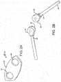
Figure 2A is a perspective view of a component of the mounting member shown inFigure 1 ; -
Figure 2B is a perspective view of components of the air maintenance tire shown inFigure 1 ; -
Figure 2C is a perspective view of another component of the mounting member shown inFigure 1 ; -
Figure 2D is a perspective view of another component of the mounting member shown inFigure 1 ; -
Figure 2E is a perspective view of another component of the mounting member shown inFigure 1 ; -
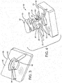
Figure 3 is a perspective view of a mold employed in the forming of the mounting member for an air maintenance tire of the present invention; -
Figure 4 is an exploded perspective view of the components shown inFigures 2A through 2E as inserted in the mold shown inFigure 3 ; -
Figure 5 is a perspective view of the components shown inFigures 2A through 2E as inserted in the mold shown inFigure 3 ; -
Figure 6 is an assembled perspective view of the components shown inFigures 2A through 2E ; -
Figure 7 is a fragmentary perspective view of a tire sidewall including a recess formed therein for receiving the mounting member and components of the pumping assembly; -
Figure 8 is a fragmentary perspective view of the mold shown inFigure 5 as disposed on the tire shown inFigure 1 and in a press; -
Figure 9 is a perspective view of a thermally conductive material component of an exemplary embodiment of the mounting member for an air maintenance tire of the present invention; -
Figure 10 is a fragmentary perspective view of an upper or top surface of the component shown inFigure 8 , including pneumatic connectors; and -
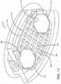
Figure 11 is a fragmentary perspective view of a lower or bottom surface of the components shown inFigure 10 . - Similar numerals refer to similar parts throughout the drawings.
- It is to be understood that the term inboard or inboardly is referred to herein as a direction corresponding to the axially inner surface or side of a tire, and the term outboard or outboardly is referred to herein as a direction corresponding to the axially outer surface or side of a tire. The term axially inwardly refers to an axial direction that is toward the center plane of a tire, and the term axially outwardly refers to an axial direction that is away from the center plane of a tire. The term radially inwardly refers to a radial direction that is toward the central axis of rotation of a tire, and the term radially outwardly refers to a radial direction that is away from the central axis of rotation of a tire.
- Turning to
Figure 1 , atire 12 is mounted on arim 14 in a conventional manner as known to those skilled in the art and defines a cavity (not shown). An exemplary air maintenance tire system, such as a valve stem-based air maintenance tire system, is indicated at 16. The airmaintenance tire system 16 includes aperistaltic pump assembly 18. Theperistaltic pump assembly 18 includes anannular air tube 20 that is received in anannular groove 38 formed in asidewall 34 of thetire 12 and/orrim 14, and in turn encloses an annular passageway (not shown). - A first connecting
tube 22 pneumatically connects to afirst end 24 of theannular air tube 20 and fluidly connects the first end of the annular air tube to avalve housing 26 of thepump assembly 18. A second connectingtube 28 pneumatically connects to asecond end 30 of theannular air tube 20 and fluidly connects the second end of the annular air tube to thevalve housing 26. - When the
tire 12 rotates under load along a ground surface, theannular air tube 20 is sequentially flattened or squeezed at the tire footprint. The sequential flattening of theannular air tube 20 and its passageway, segment by segment, directs air to thevalve housing 26. A tire valve stem (not shown), including a check valve, is fluidly connected to thevalve housing 26 and is in fluid communication with the tire cavity. When the air pressure is sufficient against the check valve and the air pressure within the tire cavity is below a set pressure level, air passes into the tire cavity. When the air pressure level within the tire cavity is at or above the set pressure, the check valve closes and air from thepump assembly 18 is vented by a relief valve in thevalve housing 26 to atmosphere. - As seen in
Figure 1 , thevalve housing 26 of thepump assembly 18 is disposed within therim 14. The connectingtubes opening 36 formed in therim 14 and extend to theair tube 20. More particularly, the first connectingtube 22 extends to a first pneumatic fitting orconnector 40, which fluidly connects the first connecting tube to thefirst end 24 of theair tube 20. The second connectingtube 28 extends to a second pneumatic fitting orconnector 42, which fluidly connects the second connecting tube to thesecond end 30 of theair tube 20. - A mounting member secures the position of the first and
second connectors tire sidewall 34, and thus secures the fluid connection of the connectingtubes air tube 20. An exemplary embodiment of the mounting member of the present invention is indicated at 50 and will be referred to as a dome for the purpose of convenience. Thedome 50 is a fairly rigid elastomer or polymer mounting member and is secured to thesidewall 34 of thetire 12, as will be described in greater detail below. - The
dome 50 includes a layered structure. More particularly, turning now toFigures 2A through 2E ,4 and6 , thedome 50 includes more than one layer, referred to herein as a plurality of layers, in which the layers are in stacked alignment with one another. For example, thedome 50 preferably includes an axiallyoutward layer 52 that forms the outer surface of the dome, which is at the outer surface of thetire sidewall 34. Theoutward layer 52 preferably is formed with a pair of openings 54, each one of which receives and positions a respectiveoutward end 56 of the first andsecond connectors outward layer 52 is also preferably formed of an abrasion-resistant elastomer, thereby providing protection to thedome 50 from road hazards and environmental conditions. - The
dome 50 also includes one or moremiddle layers middle layer 58 is adjacent the outward layer and preferably is formed with a pair ofopenings 62, each one of which includes aslot 64. Theopenings 62 enable the firstmiddle layer 58 to be positioned about the first andsecond connectors slots 64 provide a clearance that ensures the first middle layer is easily inserted about the connectors while not interfering with the pneumatic connection of the connectors to theair tube 20. - The second
middle layer 60 is adjacent the firstmiddle layer 58 and preferably is formed with a pair ofopenings 66, each one of which includes aslot 68. Theopenings 66 enable the secondmiddle layer 60 to be positioned about the first andsecond connectors slots 68 provide a clearance that ensures the second middle layer is easily inserted about the connectors while not interfering with the pneumatic connection of the connectors to theair tube 20. The secondmiddle layer 60 also is preferably formed with a radially-inwardly extendingedge 70 and a radially-outwardly extendingedge 72, each of which extends past the respective radial edges of theoutward layer 52 and the firstmiddle layer 58. Theedges middle layer 60 enable mechanical engagement with a feature formed in thetire sidewall 34. - More particularly, as shown in
Figure 7 , arecess 74 is formed in thetire sidewall 34 at a predetermined point along theannular groove 38. Thefirst connector 40 and thesecond connector 42, and thus thedome 50, are each received in therecess 74. Preferably, a feature such as an undercut 76 is formed about the radiallyinward periphery 78 and the radiallyoutward periphery 80 of therecess 74 to enable mechanical engagement of the second middle layer edges 70 and 72 and thus thedome 50 with thetire sidewall 34. In this manner, thedome 50 seats in therecess 74 and is secured to thetire sidewall 34. - Referring now to
Figures 2E ,4 and6 , thedome 50 includes an axiallyinward layer 82. Theinward layer 82 preferably is formed without openings to enable maximum surface contact with the tire sidewall surface in therecess 74, thereby enabling optimum attachment of thedome 50 to thetire sidewall 34. Theinward layer 82 also preferably includes a radially-inwardly extendingedge 84 and a radially-outwardly extendingedge 86, which align with therespective edges middle layer 60 to provide further mechanical engagement of thedome 50 with the recess undercut 76 in thetire sidewall 34. In addition, theinward layer 82 preferably is formed of an elastomer that promotes high adhesion, thereby providing further secure mounting of thedome 50 to thetire sidewall 34. - It is to be understood that the
dome 50 may include two, three, four or more layers without affecting the overall concept or operation of the invention. It is to be further understood that each layer of thedome 50 may be formed with particular features or attributes to promote desired characteristics of the dome, depending on specific design considerations. - Preferably, the
layers dome 50 are formed into an integral unit by molding, adhesion, or the like. For example, turning now toFigures 3 through 6 , amold 88 includes aninterior surface 90 that is formed with acavity 92. Afirst opening 94 extends through themold 88 from thecavity 92 and receives thefirst connector 40, while asecond opening 96 extends through the mold from the cavity and receives thesecond connector 42. Thecavity 92 is shaped to receive thelayers dome 50, the first andsecond connectors air tube 20. - Preferably, the axially
outward layer 52 is inserted into thecavity 92, followed by theconnectors outward end 56 of eachconnector outward layer 52 and is secured in a respective one of thecavity openings middle layer 58 is inserted into thecavity 92 between and about theconnectors middle layer 60 is inserted into the cavity between and about the connectors against the first middle layer. The axiallyinward layer 82 is then inserted into thecavity 92 against the secondmiddle layer 60. - As shown in
Figure 8 , themold 88 is positioned on the surface of thetire sidewall 34 over the recess 74 (Figure 7 ). Themold 88 preferably is secured in position against thetire sidewall 34 by mechanical means, such as fasteners or dowel pins. Aplaten 98 is placed into contact with themold 88 to provide pressure and/or heat to the mold to cure thedome 50 in therecess 74. - To enable the
dome 50 to be formed consistently and repeatably, eachlayer layer pre-cut layer mold 88 separately as described above, or they may be assembled and then inserted into the mold as a unit. - Turning now to
Figures 9 through 11 , one or more of the layers of thedome 50 may be or may include a thermally conductive material, such as amesh 100. When thedome 50 is cured as described above, it is desirable to promote uniform and consistent curing of the dome layers. Because theconnectors mold 88 may readily be conducted to the area of thedome 50 adjacent the connectors. However, the heat may not be conducted as well in areas of thedome 50 that are more distant from theconnectors mold 88. - To provide desirable thermal conductivity, and thus promote uniform and consistent curing, a selected layer of the
dome 50 optionally includes themesh 100. For example, one of the firstmiddle layer 58 and the second middle layer 60 (Figure 6 ) may be replaced by or include the thermallyconductive mesh 100. Themesh 100 is formed of a thermally conductive material, such as a thermally conductive polymer, and extends across the cross section of thedome 50. - The
mesh 100 is formed with a pair ofopenings 102, each one of which receives and engages a respective one of the first andsecond connectors mesh 100 with the first andsecond connectors dome 50 and promotes the transfer of heat from the connectors across the dome. Preferably, portions of theperimeter 104 of themesh 100 are disposed against or adjacent themold 88 to further promote the transfer of heat from the mold across thedome 50. - To enable the flow of elastomer into and through the
mesh 100, the mesh is preferably formed with a grid-like structure that includesribs 106 andopenings 108. With this structure, the heat distribution in thedome 50 is improved, thereby promoting uniform and consistent curing of the dome. - The above-described layered structure of the dome or mounting
member 50 for an air maintenance tire of the present invention provides consistent and repeatable forming. The layered structure also enables the dome or mountingmember 50 to include different materials with specific desirable characteristics, such an outer layer that promotes abrasion resistance and an inner layer that promotes adhesion. Moreover, thedome 50 optionally includes a thermally conductive material to promote uniform curing. - The present invention also includes a method of forming a mounting
member 50 in an air maintenance tire. The method includes steps in accordance with the description that is presented above and shown inFigures 1 through 11 . - It is to be understood that the structure of the above-described mounting member for an air maintenance tire may be altered or rearranged, or components or steps known to those skilled in the art omitted or added, without affecting the overall concept or operation of the invention.
Claims (15)
- A mounting member for use with an air maintenance tire, the tire (12) including a sidewall (34) being formed with a groove (38) for receiving an air tube (20) and a recess for receiving at least one pneumatic connector (40) that is in fluid communication with the air tube (20), the mounting member (50) comprising:a plurality of layers (52, 58, 60, 82), the layers (52, 58, 60, 82) being in stacked alignment with one another;the plurality of layers (52, 58, 60, 82) including at least an axially outward layer (52) and an axially inward layer (82); andthe mounting member (50) being configured for being received in the recess and for being secured to the tire sidewall (34) thereby securing the position of the at least one pneumatic connector (40).
- The mounting member of claim 1, wherein the outward layer (52) is formed with at least one opening (54) to receive an outward end of the at least one pneumatic connector (40).
- The mounting member of claim 1 or 2, wherein the outward layer (52) is formed of an abrasion-resistant elastomer.
- The mounting member of at least one of the previous claims, wherein the mounting member (50) further comprises at least one layer (58, 60) disposed between the outward layer (52) and the inward layer (82) or wherein the mounting member (50) comprises two layers (58, 60) disposed between the outward layer (52) and the inward layer (82).
- The mounting member of at least one of the previous claims, wherein at least one of the inward layer (82) and the layer (58, 60) being disposed between the outward layer (52) and the inward layer (82) is formed with edges (84, 82, 70, 72) that are configured to engage a feature or element formed in the tire sidewall (34).
- The mounting member of at least one of the previous claims, wherein the inward layer (82) is formed of an elastomer, preferably an elastomer that promotes adhesion.
- The mounting member of at least one of the previous claims, wherein the layers (52, 58, 60, 82) are formed into an integral unit by at least one of molding and adhesion.
- The mounting member of at least one of the previous claims, wherein the layers (52, 58, 60, 82) are pre-cut before being disposed in stacked alignment.
- The mounting member of at least one of the previous claims, further comprising a thermally conductive material being disposed in the plurality of layers (84, 82, 70, 72) and/or being incorporated into at least one of the layers (84, 82, 70, 72).
- The mounting member of at least one of the previous claims, wherein the thermally conductive material includes a thermally conductive mesh (100) and/or wherein the thermally conductive material includes a thermally conductive polymer.
- The mounting member of claim 10, wherein the mesh (100) is formed with a grid-like structure that includes ribs (106) and openings (108).
- The mounting member of at least one of the previous claims, wherein the thermally conductive material is formed with at least one opening to opening to engage the at least one pneumatic connector (40).
- An air maintenance tire including a sidewall (34) comprising a groove (38) with an air tube (20) received therein and a recess with at least one pneumatic connector (40) received therein, wherein the at least one pneumatic connector (40) is in fluid communication with the air tube (20), and wherein the tire (10) comprises a mounting member (50) in accordance with at least one of the previous claims, the mounting member (50) being received in the recess, being secured to the tire sidewall (34), and securing the position of the at least one pneumatic connector (40).
- A method of forming a mounting member for an air maintenance tire (10), the method comprising the steps of:providing a tire (10) including a sidewall (34) that is formed with a groove (38) for receiving an air tube (20) and a recess for receiving at least one pneumatic connector (40) that is in fluid communication with the air tube (20);providing a plurality of layers of material (84, 82, 70, 72);stacking the layers (84, 82, 70, 72) in alignment with one another;placing the layers (84, 82, 70, 72) in a mold (88);locating the mold (88) over the recess in the tire sidewall (34);heating the mold (88) whereby the plurality of layers (84, 82, 70, 72) are cured to form a mounting member (50) in the recess, thereby securing the position of the at least one pneumatic connector (40).
- The method of Claim 14, further comprising the step of disposing a thermally conductive material in the plurality of layers (84, 82, 70, 72).
Applications Claiming Priority (1)
| Application Number | Priority Date | Filing Date | Title |
|---|---|---|---|
| US201662425840P | 2016-11-23 | 2016-11-23 |
Publications (2)
| Publication Number | Publication Date |
|---|---|
| EP3326843A1 true EP3326843A1 (en) | 2018-05-30 |
| EP3326843B1 EP3326843B1 (en) | 2019-08-28 |
Family
ID=60331519
Family Applications (1)
| Application Number | Title | Priority Date | Filing Date |
|---|---|---|---|
| EP17202128.9A Not-in-force EP3326843B1 (en) | 2016-11-23 | 2017-11-16 | Mounting member for an air maintenance tire |
Country Status (5)
| Country | Link |
|---|---|
| US (1) | US10894452B2 (en) |
| EP (1) | EP3326843B1 (en) |
| JP (1) | JP2018083618A (en) |
| CN (1) | CN108081881B (en) |
| BR (1) | BR102017025113A2 (en) |
Families Citing this family (1)
| Publication number | Priority date | Publication date | Assignee | Title |
|---|---|---|---|---|
| US11454331B2 (en) | 2019-12-18 | 2022-09-27 | Form Create Llc | Valve cap assembly |
Citations (4)
| Publication number | Priority date | Publication date | Assignee | Title |
|---|---|---|---|---|
| EP2746074A1 (en) * | 2012-12-20 | 2014-06-25 | The Goodyear Tire & Rubber Company | Pneumatic tire with built in fastener system |
| EP2868498A1 (en) * | 2013-11-05 | 2015-05-06 | The Goodyear Tire & Rubber Company | Air maintenance tire and valve assembly and method |
| EP2889162A2 (en) * | 2013-12-16 | 2015-07-01 | The Goodyear Tire & Rubber Company | Snap-in inlet and connection method for air maintenance tire |
| US20170144493A1 (en) | 2015-11-19 | 2017-05-25 | The Goodyear Tire & Rubber Company | Valve stem-based air maintenance tire and method |
Family Cites Families (31)
| Publication number | Priority date | Publication date | Assignee | Title |
|---|---|---|---|---|
| US1682992A (en) | 1928-09-04 | of detroit | ||
| US1050886A (en) | 1910-02-23 | 1913-01-21 | Anson B Wetherell | Vehicle-tire. |
| US1134361A (en) | 1912-02-13 | 1915-04-06 | Anson B Wetherell | Self-filling tire. |
| SE183890C1 (en) | 1957-04-27 | 1963-05-21 | Pump device for pneumatic vehicle rings containing one or more pump channels concentric with the ring | |
| GB1086512A (en) | 1964-02-24 | 1967-10-11 | Ronald Leslie Sheppard | Improvements in or relating to pneumatic tyres |
| US3833041A (en) | 1973-10-11 | 1974-09-03 | Aerojet General Co | Tire inflator |
| DE3433318A1 (en) | 1984-09-11 | 1986-03-20 | Mousiol, Hans, 6000 Frankfurt | Method for inflating pneumatic tyres and pneumatic tyre for the method |
| FR2618102B1 (en) | 1987-07-15 | 1990-02-16 | Michelin & Cie | INFLATION OF A ROTATING TIRE |
| RU2106978C1 (en) | 1995-02-15 | 1998-03-20 | Леонид Михайлович Раткевич | Pneumatic tyre with automatic inflating device |
| WO2003049958A1 (en) | 2001-12-11 | 2003-06-19 | Frantisek Hrabal | Device for monitoring, maintenance and adjustment of pressure in a tyre |
| US20040112495A1 (en) | 2002-12-09 | 2004-06-17 | Curtis Arlen Weise | Self inflating tire |
| DE10335244A1 (en) | 2003-08-01 | 2005-03-10 | Bayerische Motoren Werke Ag | Device for air filling a rotating pneumatic tire |
| CZ303718B6 (en) | 2006-05-23 | 2013-04-03 | Sithold S.R.O. | Retentivity component for adjusting pneumatic tyre pressure and process for producing thereof |
| DE102007001279B4 (en) | 2007-01-08 | 2021-02-11 | Continental Reifen Deutschland Gmbh | Pneumatic vehicle tires with an electronic module |
| SE532584C2 (en) | 2008-07-15 | 2010-02-23 | Jan Folke Wallenius | Vehicle tires with a valve assembly |
| FR2943680B1 (en) * | 2009-03-31 | 2012-12-28 | Michelin Soc Tech | RUBBER AND PNEUMATIC COMPOSITION USING THE SAME. |
| US8113254B2 (en) | 2009-12-21 | 2012-02-14 | The Goodyear Tire & Rubber Company | Self-inflating tire |
| US8573270B2 (en) * | 2011-08-30 | 2013-11-05 | The Goodyear Tire & Rubber Company | Self-inflating tire and pressure regulator |
| US8875762B2 (en) | 2011-12-21 | 2014-11-04 | The Goodyear Tire & Rubber Company | Air maintenance tire and elbow connector system |
| US8985171B2 (en) | 2011-12-21 | 2015-03-24 | The Goodyear Tire & Rubber Company | Connector system and air maintenance tire assembly |
| US8915277B2 (en) | 2011-12-21 | 2014-12-23 | The Goodyear Tire & Rubber Company | Air maintenance tire and connector system |
| US8991456B2 (en) | 2012-06-28 | 2015-03-31 | The Goodyear Tire & Rubber Company | Reversible air maintenance tire and pump assembly |
| US20150059952A1 (en) | 2013-08-30 | 2015-03-05 | The Goodyear Tire & Rubber Company | Filter assembly for air maintenance tire |
| US20150059953A1 (en) | 2013-08-30 | 2015-03-05 | The Goodyear Tire & Rubber Company | Method of assembly of air maintenance tire system |
| US9272586B2 (en) * | 2013-11-05 | 2016-03-01 | The Goodyear Tire & Rubber Company | Valve stem-based air maintenance tire and method |
| US9259981B2 (en) * | 2013-11-05 | 2016-02-16 | The Goodyear Tire & Rubber Company | Valve stem-based pressure regulator system for an air maintenance tire and method |
| US9387737B2 (en) | 2014-08-07 | 2016-07-12 | The Goodyear Tire & Rubber Company | Passage tube for air maintenance tire |
| US9744816B2 (en) | 2014-08-12 | 2017-08-29 | The Goodyear Tire & Rubber Company | Air maintenance tire |
| US9533534B2 (en) * | 2014-10-22 | 2017-01-03 | The Goodyear Tire & Rubber Company | Air maintenance tire and valve assembly and method |
| US9796223B2 (en) | 2015-11-19 | 2017-10-24 | The Goodyear Tire & Rubber Company | Valve stem-based air maintenance tire and method |
| US10220658B2 (en) | 2016-01-28 | 2019-03-05 | The Goodyear Tire & Rubber Company | Valve stem-based air maintenance tire and method |
-
2017
- 2017-11-14 US US15/811,751 patent/US10894452B2/en active Active
- 2017-11-14 JP JP2017218860A patent/JP2018083618A/en active Pending
- 2017-11-16 EP EP17202128.9A patent/EP3326843B1/en not_active Not-in-force
- 2017-11-23 CN CN201711181014.8A patent/CN108081881B/en active Active
- 2017-11-23 BR BR102017025113-6A patent/BR102017025113A2/en not_active IP Right Cessation
Patent Citations (4)
| Publication number | Priority date | Publication date | Assignee | Title |
|---|---|---|---|---|
| EP2746074A1 (en) * | 2012-12-20 | 2014-06-25 | The Goodyear Tire & Rubber Company | Pneumatic tire with built in fastener system |
| EP2868498A1 (en) * | 2013-11-05 | 2015-05-06 | The Goodyear Tire & Rubber Company | Air maintenance tire and valve assembly and method |
| EP2889162A2 (en) * | 2013-12-16 | 2015-07-01 | The Goodyear Tire & Rubber Company | Snap-in inlet and connection method for air maintenance tire |
| US20170144493A1 (en) | 2015-11-19 | 2017-05-25 | The Goodyear Tire & Rubber Company | Valve stem-based air maintenance tire and method |
Also Published As
| Publication number | Publication date |
|---|---|
| CN108081881A (en) | 2018-05-29 |
| EP3326843B1 (en) | 2019-08-28 |
| US10894452B2 (en) | 2021-01-19 |
| US20180141395A1 (en) | 2018-05-24 |
| BR102017025113A2 (en) | 2018-08-14 |
| JP2018083618A (en) | 2018-05-31 |
| CN108081881B (en) | 2020-11-20 |
Similar Documents
| Publication | Publication Date | Title |
|---|---|---|
| EP3670213B1 (en) | Control system for an air maintenance tire system | |
| EP2842772A1 (en) | Tire having a pump and valve assembly | |
| EP2942211B1 (en) | Air maintenance tire assembly | |
| EP3398791B1 (en) | Wheel for an air maintenance tire system and air maintenance tire system | |
| EP2842774B1 (en) | Tire having a pump and valve assembly | |
| EP3326843B1 (en) | Mounting member for an air maintenance tire | |
| EP3902690B1 (en) | Non-pneumatic tire having reinforced support structure | |
| EP2886314B1 (en) | Tire apparatus and method of making a tire assembly | |
| EP3300931B1 (en) | Connecting member for an air maintenance tire and method of forming the same | |
| US10513157B2 (en) | Connection assembly for an air maintenance tire | |
| EP2842776A1 (en) | Tire assembly and method of making a tire assembly | |
| US20170361668A1 (en) | Air maintenance tire system component protector | |
| EP1184246A2 (en) | Master cylinder | |
| EP3170684B1 (en) | Valve stem-based air maintenance tire and method | |
| US9688108B1 (en) | Dual tire air maintenance system and method | |
| CN108058550B (en) | Air maintenance tire | |
| EP2842775B1 (en) | Tire comprising a filter assembly | |
| US20180099535A1 (en) | Air maintenance tire system component protector | |
| EP3655241B1 (en) | Bead ring design improvement | |
| US10828947B2 (en) | Pump assembly for wheel |
Legal Events
| Date | Code | Title | Description |
|---|---|---|---|
| PUAI | Public reference made under article 153(3) epc to a published international application that has entered the european phase |
Free format text: ORIGINAL CODE: 0009012 |
|
| STAA | Information on the status of an ep patent application or granted ep patent |
Free format text: STATUS: THE APPLICATION HAS BEEN PUBLISHED |
|
| AK | Designated contracting states |
Kind code of ref document: A1 Designated state(s): AL AT BE BG CH CY CZ DE DK EE ES FI FR GB GR HR HU IE IS IT LI LT LU LV MC MK MT NL NO PL PT RO RS SE SI SK SM TR |
|
| AX | Request for extension of the european patent |
Extension state: BA ME |
|
| STAA | Information on the status of an ep patent application or granted ep patent |
Free format text: STATUS: REQUEST FOR EXAMINATION WAS MADE |
|
| 17P | Request for examination filed |
Effective date: 20181130 |
|
| RBV | Designated contracting states (corrected) |
Designated state(s): AL AT BE BG CH CY CZ DE DK EE ES FI FR GB GR HR HU IE IS IT LI LT LU LV MC MK MT NL NO PL PT RO RS SE SI SK SM TR |
|
| RIC1 | Information provided on ipc code assigned before grant |
Ipc: B60C 23/12 20060101AFI20190306BHEP |
|
| GRAP | Despatch of communication of intention to grant a patent |
Free format text: ORIGINAL CODE: EPIDOSNIGR1 |
|
| STAA | Information on the status of an ep patent application or granted ep patent |
Free format text: STATUS: GRANT OF PATENT IS INTENDED |
|
| INTG | Intention to grant announced |
Effective date: 20190423 |
|
| GRAS | Grant fee paid |
Free format text: ORIGINAL CODE: EPIDOSNIGR3 |
|
| GRAA | (expected) grant |
Free format text: ORIGINAL CODE: 0009210 |
|
| STAA | Information on the status of an ep patent application or granted ep patent |
Free format text: STATUS: THE PATENT HAS BEEN GRANTED |
|
| AK | Designated contracting states |
Kind code of ref document: B1 Designated state(s): AL AT BE BG CH CY CZ DE DK EE ES FI FR GB GR HR HU IE IS IT LI LT LU LV MC MK MT NL NO PL PT RO RS SE SI SK SM TR |
|
| REG | Reference to a national code |
Ref country code: GB Ref legal event code: FG4D |
|
| REG | Reference to a national code |
Ref country code: CH Ref legal event code: EP |
|
| REG | Reference to a national code |
Ref country code: AT Ref legal event code: REF Ref document number: 1171970 Country of ref document: AT Kind code of ref document: T Effective date: 20190915 |
|
| REG | Reference to a national code |
Ref country code: IE Ref legal event code: FG4D |
|
| REG | Reference to a national code |
Ref country code: DE Ref legal event code: R096 Ref document number: 602017006539 Country of ref document: DE |
|
| REG | Reference to a national code |
Ref country code: NL Ref legal event code: MP Effective date: 20190828 |
|
| REG | Reference to a national code |
Ref country code: LT Ref legal event code: MG4D |
|
| PG25 | Lapsed in a contracting state [announced via postgrant information from national office to epo] |
Ref country code: NO Free format text: LAPSE BECAUSE OF FAILURE TO SUBMIT A TRANSLATION OF THE DESCRIPTION OR TO PAY THE FEE WITHIN THE PRESCRIBED TIME-LIMIT Effective date: 20191128 Ref country code: BG Free format text: LAPSE BECAUSE OF FAILURE TO SUBMIT A TRANSLATION OF THE DESCRIPTION OR TO PAY THE FEE WITHIN THE PRESCRIBED TIME-LIMIT Effective date: 20191128 Ref country code: NL Free format text: LAPSE BECAUSE OF FAILURE TO SUBMIT A TRANSLATION OF THE DESCRIPTION OR TO PAY THE FEE WITHIN THE PRESCRIBED TIME-LIMIT Effective date: 20190828 Ref country code: PT Free format text: LAPSE BECAUSE OF FAILURE TO SUBMIT A TRANSLATION OF THE DESCRIPTION OR TO PAY THE FEE WITHIN THE PRESCRIBED TIME-LIMIT Effective date: 20191230 Ref country code: FI Free format text: LAPSE BECAUSE OF FAILURE TO SUBMIT A TRANSLATION OF THE DESCRIPTION OR TO PAY THE FEE WITHIN THE PRESCRIBED TIME-LIMIT Effective date: 20190828 Ref country code: LT Free format text: LAPSE BECAUSE OF FAILURE TO SUBMIT A TRANSLATION OF THE DESCRIPTION OR TO PAY THE FEE WITHIN THE PRESCRIBED TIME-LIMIT Effective date: 20190828 Ref country code: SE Free format text: LAPSE BECAUSE OF FAILURE TO SUBMIT A TRANSLATION OF THE DESCRIPTION OR TO PAY THE FEE WITHIN THE PRESCRIBED TIME-LIMIT Effective date: 20190828 Ref country code: HR Free format text: LAPSE BECAUSE OF FAILURE TO SUBMIT A TRANSLATION OF THE DESCRIPTION OR TO PAY THE FEE WITHIN THE PRESCRIBED TIME-LIMIT Effective date: 20190828 |
|
| PGFP | Annual fee paid to national office [announced via postgrant information from national office to epo] |
Ref country code: DE Payment date: 20191105 Year of fee payment: 3 |
|
| PG25 | Lapsed in a contracting state [announced via postgrant information from national office to epo] |
Ref country code: AL Free format text: LAPSE BECAUSE OF FAILURE TO SUBMIT A TRANSLATION OF THE DESCRIPTION OR TO PAY THE FEE WITHIN THE PRESCRIBED TIME-LIMIT Effective date: 20190828 Ref country code: RS Free format text: LAPSE BECAUSE OF FAILURE TO SUBMIT A TRANSLATION OF THE DESCRIPTION OR TO PAY THE FEE WITHIN THE PRESCRIBED TIME-LIMIT Effective date: 20190828 Ref country code: IS Free format text: LAPSE BECAUSE OF FAILURE TO SUBMIT A TRANSLATION OF THE DESCRIPTION OR TO PAY THE FEE WITHIN THE PRESCRIBED TIME-LIMIT Effective date: 20191228 Ref country code: GR Free format text: LAPSE BECAUSE OF FAILURE TO SUBMIT A TRANSLATION OF THE DESCRIPTION OR TO PAY THE FEE WITHIN THE PRESCRIBED TIME-LIMIT Effective date: 20191129 Ref country code: LV Free format text: LAPSE BECAUSE OF FAILURE TO SUBMIT A TRANSLATION OF THE DESCRIPTION OR TO PAY THE FEE WITHIN THE PRESCRIBED TIME-LIMIT Effective date: 20190828 Ref country code: ES Free format text: LAPSE BECAUSE OF FAILURE TO SUBMIT A TRANSLATION OF THE DESCRIPTION OR TO PAY THE FEE WITHIN THE PRESCRIBED TIME-LIMIT Effective date: 20190828 |
|
| PGFP | Annual fee paid to national office [announced via postgrant information from national office to epo] |
Ref country code: FR Payment date: 20191014 Year of fee payment: 3 |
|
| REG | Reference to a national code |
Ref country code: AT Ref legal event code: MK05 Ref document number: 1171970 Country of ref document: AT Kind code of ref document: T Effective date: 20190828 |
|
| PG25 | Lapsed in a contracting state [announced via postgrant information from national office to epo] |
Ref country code: TR Free format text: LAPSE BECAUSE OF FAILURE TO SUBMIT A TRANSLATION OF THE DESCRIPTION OR TO PAY THE FEE WITHIN THE PRESCRIBED TIME-LIMIT Effective date: 20190828 |
|
| PG25 | Lapsed in a contracting state [announced via postgrant information from national office to epo] |
Ref country code: IT Free format text: LAPSE BECAUSE OF FAILURE TO SUBMIT A TRANSLATION OF THE DESCRIPTION OR TO PAY THE FEE WITHIN THE PRESCRIBED TIME-LIMIT Effective date: 20190828 Ref country code: PL Free format text: LAPSE BECAUSE OF FAILURE TO SUBMIT A TRANSLATION OF THE DESCRIPTION OR TO PAY THE FEE WITHIN THE PRESCRIBED TIME-LIMIT Effective date: 20190828 Ref country code: DK Free format text: LAPSE BECAUSE OF FAILURE TO SUBMIT A TRANSLATION OF THE DESCRIPTION OR TO PAY THE FEE WITHIN THE PRESCRIBED TIME-LIMIT Effective date: 20190828 Ref country code: EE Free format text: LAPSE BECAUSE OF FAILURE TO SUBMIT A TRANSLATION OF THE DESCRIPTION OR TO PAY THE FEE WITHIN THE PRESCRIBED TIME-LIMIT Effective date: 20190828 Ref country code: AT Free format text: LAPSE BECAUSE OF FAILURE TO SUBMIT A TRANSLATION OF THE DESCRIPTION OR TO PAY THE FEE WITHIN THE PRESCRIBED TIME-LIMIT Effective date: 20190828 Ref country code: RO Free format text: LAPSE BECAUSE OF FAILURE TO SUBMIT A TRANSLATION OF THE DESCRIPTION OR TO PAY THE FEE WITHIN THE PRESCRIBED TIME-LIMIT Effective date: 20190828 |
|
| PG25 | Lapsed in a contracting state [announced via postgrant information from national office to epo] |
Ref country code: CZ Free format text: LAPSE BECAUSE OF FAILURE TO SUBMIT A TRANSLATION OF THE DESCRIPTION OR TO PAY THE FEE WITHIN THE PRESCRIBED TIME-LIMIT Effective date: 20190828 Ref country code: SM Free format text: LAPSE BECAUSE OF FAILURE TO SUBMIT A TRANSLATION OF THE DESCRIPTION OR TO PAY THE FEE WITHIN THE PRESCRIBED TIME-LIMIT Effective date: 20190828 Ref country code: SK Free format text: LAPSE BECAUSE OF FAILURE TO SUBMIT A TRANSLATION OF THE DESCRIPTION OR TO PAY THE FEE WITHIN THE PRESCRIBED TIME-LIMIT Effective date: 20190828 Ref country code: IS Free format text: LAPSE BECAUSE OF FAILURE TO SUBMIT A TRANSLATION OF THE DESCRIPTION OR TO PAY THE FEE WITHIN THE PRESCRIBED TIME-LIMIT Effective date: 20200224 |
|
| REG | Reference to a national code |
Ref country code: DE Ref legal event code: R097 Ref document number: 602017006539 Country of ref document: DE |
|
| PLBE | No opposition filed within time limit |
Free format text: ORIGINAL CODE: 0009261 |
|
| STAA | Information on the status of an ep patent application or granted ep patent |
Free format text: STATUS: NO OPPOSITION FILED WITHIN TIME LIMIT |
|
| PG2D | Information on lapse in contracting state deleted |
Ref country code: IS |
|
| PG25 | Lapsed in a contracting state [announced via postgrant information from national office to epo] |
Ref country code: LU Free format text: LAPSE BECAUSE OF NON-PAYMENT OF DUE FEES Effective date: 20191116 Ref country code: MC Free format text: LAPSE BECAUSE OF FAILURE TO SUBMIT A TRANSLATION OF THE DESCRIPTION OR TO PAY THE FEE WITHIN THE PRESCRIBED TIME-LIMIT Effective date: 20190828 |
|
| 26N | No opposition filed |
Effective date: 20200603 |
|
| REG | Reference to a national code |
Ref country code: BE Ref legal event code: MM Effective date: 20191130 |
|
| PG25 | Lapsed in a contracting state [announced via postgrant information from national office to epo] |
Ref country code: SI Free format text: LAPSE BECAUSE OF FAILURE TO SUBMIT A TRANSLATION OF THE DESCRIPTION OR TO PAY THE FEE WITHIN THE PRESCRIBED TIME-LIMIT Effective date: 20190828 |
|
| PG25 | Lapsed in a contracting state [announced via postgrant information from national office to epo] |
Ref country code: IE Free format text: LAPSE BECAUSE OF NON-PAYMENT OF DUE FEES Effective date: 20191116 |
|
| PG25 | Lapsed in a contracting state [announced via postgrant information from national office to epo] |
Ref country code: BE Free format text: LAPSE BECAUSE OF NON-PAYMENT OF DUE FEES Effective date: 20191130 |
|
| PG25 | Lapsed in a contracting state [announced via postgrant information from national office to epo] |
Ref country code: CY Free format text: LAPSE BECAUSE OF FAILURE TO SUBMIT A TRANSLATION OF THE DESCRIPTION OR TO PAY THE FEE WITHIN THE PRESCRIBED TIME-LIMIT Effective date: 20190828 |
|
| REG | Reference to a national code |
Ref country code: DE Ref legal event code: R119 Ref document number: 602017006539 Country of ref document: DE |
|
| REG | Reference to a national code |
Ref country code: CH Ref legal event code: PL |
|
| PG25 | Lapsed in a contracting state [announced via postgrant information from national office to epo] |
Ref country code: MT Free format text: LAPSE BECAUSE OF FAILURE TO SUBMIT A TRANSLATION OF THE DESCRIPTION OR TO PAY THE FEE WITHIN THE PRESCRIBED TIME-LIMIT Effective date: 20190828 Ref country code: HU Free format text: LAPSE BECAUSE OF FAILURE TO SUBMIT A TRANSLATION OF THE DESCRIPTION OR TO PAY THE FEE WITHIN THE PRESCRIBED TIME-LIMIT; INVALID AB INITIO Effective date: 20171116 |
|
| PG25 | Lapsed in a contracting state [announced via postgrant information from national office to epo] |
Ref country code: CH Free format text: LAPSE BECAUSE OF NON-PAYMENT OF DUE FEES Effective date: 20201130 Ref country code: LI Free format text: LAPSE BECAUSE OF NON-PAYMENT OF DUE FEES Effective date: 20201130 |
|
| PG25 | Lapsed in a contracting state [announced via postgrant information from national office to epo] |
Ref country code: FR Free format text: LAPSE BECAUSE OF NON-PAYMENT OF DUE FEES Effective date: 20201130 |
|
| PG25 | Lapsed in a contracting state [announced via postgrant information from national office to epo] |
Ref country code: DE Free format text: LAPSE BECAUSE OF NON-PAYMENT OF DUE FEES Effective date: 20210601 |
|
| PG25 | Lapsed in a contracting state [announced via postgrant information from national office to epo] |
Ref country code: MK Free format text: LAPSE BECAUSE OF FAILURE TO SUBMIT A TRANSLATION OF THE DESCRIPTION OR TO PAY THE FEE WITHIN THE PRESCRIBED TIME-LIMIT Effective date: 20190828 |
|
| GBPC | Gb: european patent ceased through non-payment of renewal fee |
Effective date: 20211116 |
|
| PG25 | Lapsed in a contracting state [announced via postgrant information from national office to epo] |
Ref country code: GB Free format text: LAPSE BECAUSE OF NON-PAYMENT OF DUE FEES Effective date: 20211116 |