EP3326773A1 - Verfahren zur herstellung eines fahrzeugreifens und fertigungseinheit zur anwendung des verfahrens - Google Patents
Verfahren zur herstellung eines fahrzeugreifens und fertigungseinheit zur anwendung des verfahrens Download PDFInfo
- Publication number
- EP3326773A1 EP3326773A1 EP17193608.1A EP17193608A EP3326773A1 EP 3326773 A1 EP3326773 A1 EP 3326773A1 EP 17193608 A EP17193608 A EP 17193608A EP 3326773 A1 EP3326773 A1 EP 3326773A1
- Authority
- EP
- European Patent Office
- Prior art keywords
- vacuum
- vehicle tire
- steam
- vulcanization
- emptying
- Prior art date
- Legal status (The legal status is an assumption and is not a legal conclusion. Google has not performed a legal analysis and makes no representation as to the accuracy of the status listed.)
- Granted
Links
Images

Classifications
-
- B—PERFORMING OPERATIONS; TRANSPORTING
- B29—WORKING OF PLASTICS; WORKING OF SUBSTANCES IN A PLASTIC STATE IN GENERAL
- B29D—PRODUCING PARTICULAR ARTICLES FROM PLASTICS OR FROM SUBSTANCES IN A PLASTIC STATE
- B29D30/00—Producing pneumatic or solid tyres or parts thereof
- B29D30/06—Pneumatic tyres or parts thereof (e.g. produced by casting, moulding, compression moulding, injection moulding, centrifugal casting)
- B29D30/0601—Vulcanising tyres; Vulcanising presses for tyres
- B29D30/0662—Accessories, details or auxiliary operations
-
- B—PERFORMING OPERATIONS; TRANSPORTING
- B29—WORKING OF PLASTICS; WORKING OF SUBSTANCES IN A PLASTIC STATE IN GENERAL
- B29C—SHAPING OR JOINING OF PLASTICS; SHAPING OF MATERIAL IN A PLASTIC STATE, NOT OTHERWISE PROVIDED FOR; AFTER-TREATMENT OF THE SHAPED PRODUCTS, e.g. REPAIRING
- B29C35/00—Heating, cooling or curing, e.g. crosslinking or vulcanising; Apparatus therefor
- B29C35/02—Heating or curing, e.g. crosslinking or vulcanizing during moulding, e.g. in a mould
- B29C35/04—Heating or curing, e.g. crosslinking or vulcanizing during moulding, e.g. in a mould using liquids, gas or steam
- B29C35/049—Heating or curing, e.g. crosslinking or vulcanizing during moulding, e.g. in a mould using liquids, gas or steam using steam or damp
-
- B—PERFORMING OPERATIONS; TRANSPORTING
- B29—WORKING OF PLASTICS; WORKING OF SUBSTANCES IN A PLASTIC STATE IN GENERAL
- B29D—PRODUCING PARTICULAR ARTICLES FROM PLASTICS OR FROM SUBSTANCES IN A PLASTIC STATE
- B29D30/00—Producing pneumatic or solid tyres or parts thereof
- B29D30/06—Pneumatic tyres or parts thereof (e.g. produced by casting, moulding, compression moulding, injection moulding, centrifugal casting)
- B29D30/0601—Vulcanising tyres; Vulcanising presses for tyres
- B29D30/0662—Accessories, details or auxiliary operations
- B29D2030/0666—Heating by using fluids
- B29D2030/0667—Circulating the fluids, e.g. introducing and removing them into and from the moulds; devices therefor
- B29D2030/067—Circulating the fluids, e.g. introducing and removing them into and from the moulds; devices therefor the vulcanizing fluids being gases or vapours
Definitions
- the invention relates to a method for producing a vehicle tire and a production plant for the application of the method.
- a method for producing a vehicle tire using a vulcanization tool is already known from DE 34 37 628 A1 known.
- elastically deformable molded body is filled with a pressurized gas, in which it is in accordance with DE 34 37 628 A1 is nitrogen.
- the gas is removed from the shaped body in a first emptying step until the pressure level in the shaped body corresponds approximately to the normal air pressure.
- a subsequent emptying step takes place by means of a vacuum, the complete removal of any remaining residues of the gas from the molding, which corresponds to a suction due to the vacuum.
- liquid ring pumps require energy for their operation and also generate acquisition costs and maintenance costs, which arise for example for maintenance and repairs.
- a major disadvantage of the previously known and in use vulcanization tools is also that considerable amounts of energy are needed to cool the vacuum pump and the storage tank. This results in a total too long emptying times of the molding, high energy costs, too short life of the molding, since this is significantly burdened mechanically and thermally, high investment costs and significant maintenance.
- the invention has for its object to define a method for producing a vehicle tire using a Vulkanisationstechnikmaschinemaschinees that leads with the simplest possible means, with reduced effort and at reduced cost to improve the production and an increase in the number of vehicle tires produced. For the application of the method beyond a production unit should be described.
- a method for producing a vehicle tire using a vulcanization tool wherein during vulcanization to form the after filling of the vehicle tire with air-filled inner cavity of the vehicle tire inserted into the vehicle tire blank, elastically deformable molded body is filled with a pressurized gas after completion the vulcanization is removed in a first emptying step from the molding, until the pressure level in the molded body corresponds to the normal air pressure in order to completely remove residual gas from the molded body in a subsequent emptying step by means of a vacuum, has been further developed according to the invention in that steam is used to lower the temperature of the steam to produce the vacuum ,
- the invention thus goes a completely new way in the production of vehicle tires.
- a known vapor condensation with a temperature reduction to generate the vacuum namely, a cost-intensive vacuum pump per manufacturing unit can be saved as part of a production unit suitable for the production of a vehicle tire.
- the production unit used for the production of a vehicle tire is simplified considerably, which also reduces overall manufacturing costs.
- the negative pressure or the vacuum is generated according to the invention by the condensation of water vapor.
- a vacuum pump can be saved, but instead of the above-mentioned and previously required two pipes for emptying the molding and the vacuum guide, there is according to the invention only a single flow pipe, which is constantly subjected to negative pressure or a vacuum.
- the invention is particularly simple to implement if, according to a first embodiment, the steam condensation is a water vapor condensation.
- the thermodynamic reaction conditions of water vapor are relative easy to determine and follow.
- special safety requirements do not have to be fulfilled when using steam, so that this measure is of decisive advantage for the invention.
- a production unit for producing vehicle tires may have one or more vulcanization tools. It is important that the invention is applicable to all vulcanization tools, whereby the effectiveness of the entire production can be significantly increased.
- the vacuum can be stored in storage tanks, the energy expenditure for the production of the vacuum can be reduced, since initially the existing reserves can be used. Overall, the vacuum can therefore be used not only for emptying the molding, but also for the removal of the precipitated as a result of the steam condensation steam condensate.
- the steam condensate was previously a significant problem in the production, since the resulting moisture was formed by existing temperature differences and had to be removed from the vulcanization tool laboriously. By using the vacuum, this step can be significantly simplified.
- the steam condensate can be discharged into a cyclone or centrifugal separator, which generates a separation between liquid and vapor. This has the consequence that both the liquid is optimally removed and liquid and the steam are available again. Overall, considerable savings potential can thus be exploited, with the production of a vehicle tire can be largely designed as a closed system and thus works very energy-efficient overall.
- a further proposal of the invention is that the separated vapor is discharged into a condenser and sprayed into the recirculation water.
- the recycle water can be obtained from a heat exchanger, which also supplies once generated heat energy reuse.
- non-condensable fractions in the steam used can be either solids or gases.
- the solids include, for example, impurities in the water, such as lime or other deposits and components of vehicle tire manufacturing.
- the jet pump serves to remove non-condensable gases within the mixture and functions according to the venturi principle. It thus generates a negative pressure and accelerates the flow.
- a production unit for the application of the method described above is characterized in that the production unit is a vulcanization tool with an elastically deformable molded body and only a single flow pipe for filling and emptying of the molded body and a vacuum generating unit for generating the vacuum required for the emptying of the molded body by lowering the temperature in a steam condensation, with a cyclone (Moisture trap), a condenser and a heat exchanger, wherein the cyclone is flow-conductively connected to the flow line pipe and a collecting container for receiving condensate and impurities.
- a cyclone Melisture trap
- Such a production unit is very simple and thus allows energy-saving and reduced cost and investment compared to known solutions, the production of vehicle tires.
- the vacuum generating unit additionally comprises a jet pump.
- the jet pump can be used to remove non-condensable constituents of the water vapor or in addition to the reinforcement of the vacuum used, but ultimately depends on the composition of the gaseous constituents of the water vapor.
- FIG. 1 shows a section of a section through a simplified representation of a vulcanization tool 2 for producing a vehicle tire 1.
- the blank of the vehicle tire 1 shown here is located in a cavity 8 of the Vulkanisationstechnikmaschinemaschinees 2, which forms the negative shape of the vehicle tire 1 to be generated.
- a molded body 3 is used, which is filled with pressurized water vapor.
- the mutually spreading pressure within the molding 3 is in the FIG. 1 symbolized by several arrows.
- a valve 9 is present, which opens or closes a supply line 10 in the present case.
- the aforementioned gas is introduced into the interior of the molded body 3 and removed after completion of the vehicle tire 1 again from the molded body 3.
- This basic structure of a vulcanization tool 2 is known per se. What is new here is to generate a vacuum by means of a steam condensation with a temperature reduction, which completely removes the gaseous water vapor present in the cavity of the shaped body 3 from the shaped body 3 after completion of the vehicle tire 1.
- the vulcanization tool 2 is a filled with a pressurized water vapor and / or optionally with gases such as nitrogen, mold body 3, which is inserted into the inner cavity of the vehicle tire 1.
- the vulcanization tool 2 forms a first core of the illustrated production unit.
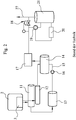
- Another core of the manufacturing unit consists of the vacuum generating unit for providing the required for the extraction of the gas from the molding 3 water vapor or gas. This vacuum is provided here by means of complex measures. So first, a vacuum pump 19 is required. The vacuum generated by the vacuum pump 19 is stored in a vacuum tank 14.
- the vacuum pump 19 heats up during its operation and must therefore by means of a Pump cooler 20 are cooled to an operating temperature, which requires additional energy.
- the cooling capacity for the operation of a vacuum cooler 17 for cooling the vacuum is in the total energy balance of in FIG. 2 to be considered, known production unit.
- a tank 21 serves as a buffer for the delivery of the gas to the environment, which takes place through the discharge line 27 and is indicated by an arrow.
- To control the discharge amount and the volume flow of the vacuum pump 19 is a two-way valve 18. As shown in FIG. 2 becomes clear, the cost of generating the vacuum in known production units for producing a vehicle tire 1 in a vulcanization tool 2 is relatively high and energy-intensive. For discharging the gas present in the molded body 3 is used in the in FIG.
- a collecting container 13 for these contaminants is present, which is integrated into the flow line system and connected to the drain line 12.
- a pump 16 is also arranged, so that the emptying of the vacuum tank 14 is possible.
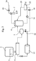
- FIG. 3 a manufacturing unit according to the invention shown. It should be noted that no longer a drain line 11 and an additional vacuum line 12 are used, but only a combined flow pipe 4, which is used for the emptying of the molding 3.
- An essential part of this production unit is a vacuum generating unit, which feeds the flow line pipe 4 in the present case.
- the steam condensate is conducted into a cyclone 5, that is to say into a centrifugal separator, in which the liquid constituents of the steam condensate are separated from the steam. From here, the water vapor passes into a condenser 6, is injected into the return water from the heat exchanger 22 via the flow line 23 to ensure effective condensation.
- the steam condensate is (indirectly) also used for heat recovery.
- a used, in the FIG. 3 Not shown filter is also used to prevent damage to the heat exchanger 22 due to contamination.
- the soils mentioned are mainly rubber particles.
- the non-condensable gas fractions, which account for about 5% proportion, are removed by a jet pump 7, which in turn is driven by water vapor at about 3 bar.
- the discharge of these gas components via the drain line 25 to the jet pump 7.
- the cyclone 5 is coupled with the interposition of a valve 26 in flow-conducting manner to a collecting container 13, is collected in the contaminated condensate and removed from the system.
- the jet pump 7 is also supplied via the steam supply line 24 steam so that their operation is guaranteed.
- a pump 16 is also available.
- the flow guidance can also be controlled via a plurality of two-way or multi-way valves 18.
- a collecting container 13 is integrated for impurities.
- the pressure within the molded body 3 is increased according to the invention in a very short time of 0 and kept at a high level for a certain time, which corresponds to the production time of the vehicle tire 1 in the vulcanization tool 2. Subsequently, the pressure in the molded body 2 via the flow line pipe 4 in two stages, first to the atmospheric air pressure and then reduced to a negative pressure, ie to a vacuum, the vacuum is always provided via the flow pipe 4 is available. This has the consequence that the pressure within the molded body 3 drops below the normal air pressure, so that thereby the last still remaining in the molded body 3 remains of the water vapor or the moisture are removed from the molded body 3.
Landscapes
- Physics & Mathematics (AREA)
- Health & Medical Sciences (AREA)
- Oral & Maxillofacial Surgery (AREA)
- Thermal Sciences (AREA)
- Engineering & Computer Science (AREA)
- Mechanical Engineering (AREA)
- Moulds For Moulding Plastics Or The Like (AREA)
- Heating, Cooling, Or Curing Plastics Or The Like In General (AREA)
Abstract
Description
- Die Erfindung betrifft ein Verfahren zur Herstellung eines Fahrzeugreifens sowie eine Fertigungsanlage zur Anwendung des Verfahrens.
- Ein Verfahren zur Herstellung eines Fahrzeugreifens unter Verwendung eines Vulkanisationswerkzeuges ist bereits aus der
DE 34 37 628 A1 bekannt. Während der Vulkanisation wird gemäß dem Offenbarungsgehalt der Druckschrift zur Ausbildung des nach der Fertigstellung des Fahrzeugreifens mit Luft befüllbaren Innenhohlraumes des Fahrzeugreifens ein in den Fahrzeugreifenrohling eingesetzter, elastisch verformbarer Formkörper mit einem unter Druck stehenden Gas gefüllt, bei dem es sich gemäß derDE 34 37 628 A1 um Stickstoff handelt. Im Anschluss an die Vulkanisation wird das Gas in einem ersten Entleerungsschritt aus dem Formkörper abgeführt, bis das Druckniveau in dem Formkörper etwa dem Normalluftdruck entspricht. In einem darauf folgenden Entleerungsschritt erfolgt mittels eines Vakuums die vollständige Abführung noch vorhandener Reste des Gases aus dem Formkörper, was infolge des Vakuums einem Absaugen entspricht.
Dieses, in der Herstellungspraxis von Fahrzeugreifen bisher eingesetzte Verfahren erfordert jedoch zwei getrennte Rohrleitungen, von denen eine für die Entleerung und die andere für das Vakuum genutzt werden. Dabei wird zunächst eine Dampf-Kondensat-Mischung aus dem Formkörper in ein Ablaufrohr entleert, um den ursprünglich im Formkörper noch vorhandenen Überdruck von etwa 12 bar auf Atmosphärendruck zu reduzieren. Nachdem der Druck in die Nähe des Atmosphärendrucks abgesenkt wurde, wird ein Vakuumventil geöffnet, um das verbleibende Kondensat aus dem Formkörper abzusaugen. Zur Erzeugung des benötigten Vakuums kommen gegenwärtig Vakuumpumpen zum Einsatz, bei denen es sich um Flüssigkeitsringpumpen handelt. Diese stellen einen Unterdruck von ungefähr 0,4 bis 0,9 bar bereit. Davon unabhängig ist es bereits bekannt, ein erzeugtes Vakuum in einem Vorratstank zu speichern. Die zuvor erwähnten Flüssigkeitsringpumpen benötigen für ihren Betrieb Energie und erzeugen zudem Anschaffungskosten sowie Unterhaltungskosten, die beispielsweise für die Wartung und Reparaturen entstehen. Ein wesentlicher Nachteil der bislang bekannten und im Einsatz befindlichen Vulkanisationswerkzeuge besteht ferner darin, dass beträchtliche Energiemengen benötigt werden, um die Vakuumpumpe und den Vorratstank zu kühlen. Daraus ergeben sich insgesamt zu lange Entleerungszeiten des Formkörpers, hohe Energiekosten, eine zu kurze Lebensdauer des Formkörpers, da dieser mechanisch und thermisch erheblich belastet wird, hohe Investitionskosten und ein maßgeblicher Wartungsaufwand. - Der Erfindung liegt die Aufgabe zugrunde, ein Verfahren zur Herstellung eines Fahrzeugreifens unter Verwendung eines Vulkanisationswerkzeuges zu definieren, das mit möglichst einfachen Mitteln, mit verringertem Aufwand und mit reduzierten Kosten zu einer Verbesserung der Herstellung und einer Erhöhung der Zahl der produzierten Fahrzeugreifen führt. Zur Anwendung des Verfahrens sollte darüber hinaus eine Fertigungseinheit beschriebenen werden.
- Die Erfindung löst diese Aufgabenstellung mit den Merkmalen der unabhängigen Patentansprüche 1 und 9.
Weitere Ausgestaltungen der Erfindung sind Gegenstand der sich jeweils anschließenden Unteransprüche. - Ein Verfahren zur Herstellung eines Fahrzeugreifens unter Verwendung eines Vulkanisationswerkzeuges, wobei während der Vulkanisation zur Ausbildung des nach der Fertigstellung des Fahrzeugreifens mit Luft befüllbaren Innenhohlraumes des Fahrzeugreifens ein in den Fahrzeugreifenrohling eingesetzter, elastisch verformbarer Formkörper mit einem unter Druck stehenden Gas gefüllt wird, das nach Beendigung der Vulkanisation in einem ersten Entleerungsschritt aus dem Formkörper abgeführt wird, bis das Druckniveau in dem Formkörper dem Normalluftdruck entspricht, um in einem darauf folgenden Entleerungsschritt mittels eines Vakuums noch vorhandene Reste des Gases vollständig aus dem Formkörper abzusaugen, wurde erfindungsgemäß dahingehend weitergebildet, dass zur Erzeugung des Vakuums eine Dampfkondensation mit einer Absenkung der Temperatur des Dampfes genutzt wird.
- Die Erfindung geht damit einen vollkommen neuen Weg bei der Herstellung von Fahrzeugreifen. Durch den Einsatz einer an sich bekannten Dampfkondensation mit einer Temperaturabsenkung zur Erzeugung des Vakuums kann nämlich im Rahmen einer für die Herstellung eines Fahrzeugreifens geeigneten Fertigungseinheit eine kostenintensive Vakuumpumpe je Fertigungseinheit eingespart werden. Damit vereinfacht sich die zum Einsatz kommende Fertigungseinheit zur Herstellung eines Fahrzeugreifens erheblich, was zudem insgesamt die Fertigungskosten reduziert.
Der Unterdruck beziehungsweise das Vakuum wird erfindungsgemäß durch das Kondensieren von Wasserdampf erzeugt. Damit kann jedoch nicht nur eine Vakuumpumpe eingespart werden, sondern anstelle der eingangs genannten und bislang erforderlichen zwei Rohrleitungen für das Entleeren des Formkörpers und die Vakuumführung gibt es erfindungsgemäß nur noch ein einziges Strömungsleitungsrohr, das ständig mit Unterdruck beziehungsweise einem Vakuum beaufschlagt ist.
Daraus ergeben sich die entscheidenden Vorteile bei der Fahrzeugreifenherstellung, dass vorliegend weniger Zeit für die Erzeugung eines Fahrzeugreifens benötigt wird und damit eine höhere Effektivität gegeben ist. Dies resultiert daraus, dass sich der Formkörper durch das permanent anliegende Vakuum wesentlich schneller entleert, als dies bisher der Fall war. Zudem ergeben sich mit der Erfindung maßgebliche Energieeinsparungspotenziale und ein entscheidend geringerer Wartungsaufwand, da insgesamt durch die Vereinfachung der gesamten Fertigungseinheit zur Herstellung eines Fahrzeugreifens weniger bewegliche Teile benötigt werden benötigt werden, als bislang. - Besonders einfach umsetzbar ist die Erfindung dann, wenn gemäß einer ersten Ausgestaltung die Dampfkondensation eine Wasserdampfkondensation ist. Die thermodynamischen Reaktionsbedingungen von Wasserdampf sind verhältnismäßig einfach zu bestimmen und einzuhalten. Besondere Sicherheitsanforderungen müssen zudem beim Einsatz von Wasserdampf nicht erfüllt werden, so dass diese Maßnahme von maßgeblichen Vorteil für die Erfindung ist.
- Wie zuvor bereits ausgeführt wurde, besteht eine andere Weiterbildung der Erfindung darin, dass lediglich ein einziges Strömungsleitungsrohr für die Entleerung des Formkörpers und das Bereitstellen des Vakuums genutzt wird. Damit weist dieses eine Doppelfunktion auf und es kann ein komplettes Rohrleitungssystem eingespart werden, was insgesamt zu einer erheblichen Vereinfachung der Fertigungseinheit zur Herstellung eines Fahrzeugreifens führt. An dieser Stelle ist anzumerken, dass eine Fertigungseinheit zur Herstellung von Fahrzeugreifen ein oder mehrere Vulkanisationswerkzeuge aufweisen kann. Dabei ist es von Bedeutung, dass die Erfindung für sämtliche Vulkanisationswerkzeuge anwendbar ist, wodurch die Effektivität der gesamten Produktion erheblich gesteigert werden kann.
- Da sich das Vakuum in Vorratstanks speichern lässt, ist auch der energetische Aufwand zur Herstellung des Vakuums reduzierbar, da zunächst auf die vorhandenen Reserven zurückgegriffen werden kann. Insgesamt kann das Vakuum demnach nicht nur zur Entleerung des Formkörpers verwendet werden, sondern auch zum Entzug des infolge der Dampfkondensation ausfallenden Dampfkondensats. Das Dampfkondensat stellte bislang ein maßgebliches Problem bei der Fertigung dar, da die daraus resultierende Feuchtigkeit sich durch vorhandene Temperaturunterschiede ausbildete und mühevoll aus dem Vulkanisationswerkzeug entfernt werden musste. Durch den Einsatz des Vakuums lässt sich dieser Schritt maßgeblich vereinfachen.
- Zudem kann entsprechend einem vorteilhaften Lösungsvorschlag nach der Erfindung das Dampfkondensat in einen Zyklon oder Fliehkraftabscheider abgeführt werden, der eine Trennung zwischen Flüssigkeit und Dampf erzeugt. Dies hat zur Folge, dass sowohl die Flüssigkeit optimal abgeführt wird und Flüssigkeit sowie der Dampf erneut zur Verfügung stehen. Insgesamt lassen sich somit erhebliche Einsparungspotenziale ausschöpfen, wobei die Herstellung eines Fahrzeugreifens weitgehend als geschlossenes System ausgebildet werden kann und dadurch insgesamt sehr energieeffizient funktioniert.
- Zur Verbesserung der Kondensation geht ein weiterführender Vorschlag der Erfindung dahin, dass der abgeschiedene Dampf in einen Kondensator abgeführt und in den zudem Rückführungswasser eingesprüht wird. Das Rückführungswasser lässt sich aus einem Wärmetauscher gewinnen, der darüber hinaus einmal erzeugte Wärmeenergie einer erneuten Nutzung zuführt.
- In dem erfindungsgemäßen System zur Herstellung eines Fahrzeugreifens gibt es nicht kondensierbare Anteile in dem zum Einsatz kommenden Dampf. Dies können entweder Festkörper oder Gase sein. Zu den Festkörpern gehören beispielsweise Verunreinigungen im Wasser, wie Kalk oder andere Ablagerungen und Bestandteile der Fahrzeugreifenherstellung. Zu deren Abscheidung dient ein Zyklon, während zur Abscheidung der Gase eine von Dampf angetriebene Strahlpumpe verwendet wird. Die Strahlpumpe dient dabei der Entfernung nicht kondensierbarer Gase innerhalb der Mischung und funktioniert nach dem Venturi-Prinzip. Sie erzeugt folglich einen Unterdruck und beschleunigt die Strömung.
- Im Zuge der Energieeinsparungspotenziale der Erfindung ist es auch sinnvoll, eine Wärmerückgewinnung zu nutzen, um Wärmeenergie einzusparen. Wie bereits ausgeführt wurde, kommt hierfür wenigstens ein Wärmetauscher zum Einsatz der in die Fertigungseinheit integriert wird. Die einmal erzeugte Wärme geht damit nicht verloren, sondern ist mehrfach wiederverwendbar.
- Eine Fertigungseinheit zur Anwendung des zuvor beschriebenen Verfahrens ist dadurch gekennzeichnet, dass die Fertigungseinheit ein Vulkanisationswerkzeug mit einem elastisch verformbaren Formkörper und lediglich ein einziges Strömungsleitungsrohr zur Befüllung und Entleerung des Formkörpers sowie eine Vakuumerzeugungseinheit zur Erzeugung des für die Entleerung des Formkörpers benötigten Vakuums durch Absenkung der Temperatur bei einer Dampfkondensation, mit einem Zyklon (Feuchtigkeitsabscheider), einem Kondensator und einem Wärmetauscher aufweist, wobei der Zyklon strömungsleitend mit dem Strömungsleitungsrohr und einem Sammelbehälter zur Aufnahme von Kondensat und Verunreinigungen verbunden ist.
- Eine derartige Fertigungseinheit ist sehr einfach aufgebaut und ermöglicht damit Energie sparend sowie mit reduziertem Aufwand und verringerten Investitionen gegenüber bekannten Lösungen die Herstellung von Fahrzeugreifen.
- Eine Ausgestaltung der Fertigungseinheit besteht darin, dass die Vakuumerzeugungseinheit zusätzlich eine Strahlpumpe umfasst. Die Strahlpumpe kann dabei zur Abführung nicht kondensierbarer Bestandteile des Wasserdampfes genutzt werden oder zusätzlich zur Verstärkung des Vakuums zum Einsatz kommen, was letztlich jedoch von der Zusammensetzung der gasförmigen Bestandteile des Wasserdampfes abhängt.
- Die Erfindung wird nachfolgend anhand der beigefügten Zeichnungen näher erläutert. Die gezeigten Ausführungsbeispiele stellen dabei keine Einschränkung auf die dargestellten Varianten dar, sondern dienen lediglich der Erläuterung eines Prinzips der Erfindung. Gleiche oder gleichartige Bauteile werden stets mit denselben Bezugsziffern bezeichnet. Um die erfindungsgemäße Funktionsweise veranschaulichen zu können, sind in den Figuren nur stark vereinfachte Prinzipdarstellungen gezeigt, bei denen auf die für die Erfindung nicht wesentlichen Bauteile verzichtet wurde. Dies bedeutet jedoch nicht, dass derartige Bauteile bei einer erfindungsgemäßen Lösung nicht vorhanden sind.
- Es zeigt:
- Figur 1:
- einen Schnitt durch eine vereinfachte Darstellung eines ausschnittsweise gezeigten Vulkanisationswerkzeuges,
- Figur 2:
- eine Fertigungseinheit zur Herstellung eines Fahrzeugreifens nach dem Stand der Technik
und - Figur 3:
- beispielhaft und im Vergleich eine erfindungsgemäße Fertigungseinheit zur Herstellung eines Fahrzeugreifens.
- Die
Figur 1 zeigt ausschnittsweise einen Schnitt durch eine vereinfachte Darstellung eines Vulkanisationswerkzeuges 2 zur Herstellung eines Fahrzeugreifens 1. Der hier dargestellte Rohling des Fahrzeugreifens 1 befindet sich in einem Hohlraum 8 des Vulkanisationswerkzeuges 2, der die negative Form des zu erzeugenden Fahrzeugreifens 1 bildet. In den nach der Fertigstellung des Fahrzeugreifens 1 mit Luft befüllbaren Innenhohlraum ist ein Formkörper 3 eingesetzt, der mit unter Druck stehendem Wasserdampf gefüllt wird. Der sich allseitig ausbreitende Druck innerhalb des Formkörpers 3 ist in derFigur 1 durch mehrere Pfeile symbolisiert. Zur Einbringung des unter Druck stehenden Wasserdampfes ist ein Ventil 9 vorhanden, das im vorliegenden Fall eine Zuführungsleitung 10 öffnet oder verschließt. Über die Zuführungsleitung 10 wird das zuvor erwähnte Gas in den Innenraum des Formkörpers 3 eingebracht und nach Fertigstellung des Fahrzeugreifens 1 wieder aus dem Formkörper 3 entfernt. Dieser grundsätzliche Aufbau eines Vulkanisationswerkzeuges 2 ist an sich bekannt. Neu ist hierbei, durch eine Dampfkondensation mit einer Temperaturabsenkung ein Vakuum zu erzeugen, das den in dem Hohlraum des Formkörpers 3 vorhandenen, gasförmigen Wasserdampf nach Fertigstellung des Fahrzeugreifens 1 vollständig aus dem Formkörper 3 entfernt. - Eine aus dem Stand der Technik bekannte Fertigungseinheit zur Herstellung eines Fahrzeugreifens 1, geht aus der Darstellung in
Figur 2 hervor. In dem Vulkanisationswerkzeug 2 befindet sich ein mit einem unter Druck stehenden Wasserdampf und/oder gegebenenfalls mit Gasen, wie Stickstoff, befüllbarer Formkörper 3, der in den Innenhohlraum des Fahrzeugreifens 1 eingesetzt ist. Das Vulkanisationswerkzeug 2 bildet ein erstes Kernstück der dargestellten Fertigungseinheit. Ein weiteres Kernstück der Fertigungseinheit besteht aus der Vakuumerzeugungseinheit zur Bereitstellung des für die Absaugung des Gases aus dem Formkörper 3 erforderlichen Wasserdampfes beziehungsweise Gases. Dieses Vakuum wird hierbei mittels aufwändiger Maßnahmen bereitgestellt. So ist zunächst eine Vakuumpumpe 19 erforderlich. Das mit der Vakuumpumpe 19 erzeugte Vakuum wird in einem Vakuumtank 14 gespeichert. Die Vakuumpumpe 19 erwärmt sich während ihres Betriebes und muss folglich mittels eines Pumpenkühlers 20 auf eine Betriebstemperatur gekühlt werden, was zusätzliche Energie erfordert. Auch die Kühlleistung für den Betrieb eines Vakuumkühlers 17 zur Kühlung des Vakuums ist bei der Gesamtenergiebilanz der inFigur 2 gezeigten, bekannten Fertigungseinheit zu berücksichtigen.
Ein Tank 21 dient hierbei als Puffer für die Abgabe des Gases an die Umgebung, was durch die Abführleitung 27 erfolgt und durch einen Pfeil angedeutet ist. Zur Regelung der Abgabemenge und des Volumenstromes der Vakuumpumpe 19 dient ein Zweiwegventil 18. Wie aus derFigur 2 deutlich wird, ist der Aufwand für die Erzeugung des Vakuums bei bekannten Fertigungseinheiten zur Herstellung eines Fahrzeugreifens 1 in einem Vulkanisationswerkzeug 2 verhältnismäßig hoch und energieintensiv.
Zur Abführung des in dem Formkörper 3 vorhandenen Gases dient bei der inFigur 2 gezeigten Fertigungseinheit eine Entleerungsleitung 11 sowie zum Abführen der noch verbliebenen Reste eine Vakuumleitung 12. Da bei der Entleerung des Formkörpers 3 auch Verunreinigungen entstehen, ist ein Sammelbehälter 13 für diese Verunreinigungen vorhanden, der in das Strömungsleitungssystem integriert und mit der Entleerungsleitung 12 verbunden ist. In der Leitung 15 ist darüber hinaus eine Pumpe 16 angeordnet, so dass die Entleerung des Vakuumtanks 14 möglich ist. - Im Unterschied zu der Darstellung in
Figur 2 wird in derFigur 3 eine erfindungsgemäße Fertigungseinheit gezeigt. Hierbei ist zu beachten, dass nicht mehr eine Entleerungsleitung 11 und eine zusätzliche Vakuumleitung 12 zum Einsatz kommen, sondern lediglich ein kombiniertes Strömungsleitungsrohr 4, das für die Entleerung des Formkörpers 3 genutzt wird.
Wesentlicher Bestandteil dieser Fertigungseinheit ist eine Vakuumserzeugungseinheit, die vorliegend das Strömungsleitungsrohr 4 speist. Das Dampfkondensat wird hierbei in einen Zyklon 5, also in einen Fliehkraftabscheider, geführt, in dem die flüssigen Bestandteile des Dampfkondensats von dem Wasserdampf abgeschieden werden. Von hier aus gelangt der Wasserdampf in einen Kondensator 6, in den Rückführungswasser aus dem Wärmetauscher 22 über die Strömungsleitung 23 eingesprüht wird, um ein effektives Kondensieren zu gewährleisten. Das Dampfkondensat wird (indirekt) auch zur Wärmerückgewinnung verwendet. Ein zum Einsatz kommender, in derFigur 3 nicht gezeigter Filter wird darüber hinaus dazu verwendet, eine Beschädigung am Wärmetauscher 22 aufgrund von Verschmutzungen zu verhindern. Bei den erwähnten Verschmutzungen handelt es sich hauptsächlich um Kautschuk-Partikel. Die nicht kondensierbaren Gasanteile, die anteilig etwa 5% ausmachen, werden von einer Strahlpumpe 7 entfernt, die ihrerseits von Wasserdampf bei etwa 3 bar angetrieben wird. Die Abführung dieser Gasanteile erfolgt über die Abflussleitung 25 an der Strahlpumpe 7. Der Zyklon 5 ist unter Zwischenschaltung eines Ventils 26 strömungsleitend an einen Sammelbehälter 13 gekoppelt, in dem verunreinigtes Kondensat gesammelt und dem System entnommen wird. Der Strahlpumpe 7 wird darüber hinaus über die Dampfzuführleitung 24 Wasserdampf zugeführt, sodass ihr Betrieb gewährleistet ist. Zur Aufrechterhaltung einer Strömung innerhalb der Vakuumerzeugungseinheit steht zudem eine Pumpe 16 zur Verfügung. Die Strömungsführung lässt sich zudem über mehrere Zwei- oder Mehrwegeventile 18 steuern. Auch in das erfindungsgemäße Strömungssystem ist ein Sammelbehälter 13 für Verunreinigungen integriert.
Der Druck innerhalb des Formkörpers 3 wird erfindungsgemäß in einer sehr kurzen Zeit von 0 erhöht und für eine bestimmte Zeit auf dem hohen Niveau gehalten, was der Herstellungszeit des Fahrzeugreifens 1 in dem Vulkanisationswerkzeug 2 entspricht. Im Anschluss daran wird der Druck in dem Formkörper 2 über das Strömungsleitungsrohr 4 in zwei Stufen zunächst bis auf den atmosphärischen Luftdruck und danach bis auf einen Unterdruck, also bis zu einem Vakuum abgebaut, wobei das Vakuum stets über das Strömungsleitungsrohr 4 zur Verfügung gestellt ist. Dies hat zur Folge, dass der Druck innerhalb des Formkörpers 3 bis unter den Normalluftdruck absinkt, so dass dadurch auch die letzten noch im Formkörper 3 verbliebenen Reste des Wasserdampfes beziehungsweise der Feuchtigkeit aus dem Formkörper 3 entfernt werden. -
- 1
- Fahrzeugreifen
- 2
- Vulkanisationswerkzeug
- 3
- Formkörper
- 4
- Strömungsleitungsrohr
- 5
- Zyklon
- 6
- Kondensator
- 7
- Strahlpumpe
- 8
- Hohlraum
- 9
- Ventil
- 10
- Zuführungsleitung (zum Strömungsleitungsrohr)
- 11
- Entleerungsleitung
- 12
- Vakuumleitung
- 13
- Sammelbehälter
- 14
- Vakuumtank
- 15
- Leitung
- 16
- Pumpe
- 17
- Vakuumkühler
- 18
- Zweiwegeventil
- 19
- Vakuumpumpe
- 20
- Pumpenkühler
- 21
- Tank
- 22
- Wärmetauscher
- 23
- Strömungsleitung
- 24
- Dampfzuführleitung
- 25
- Abflussleitung
- 26
- Ventil
- 27
- Abführleitung
Claims (10)
- Verfahren zur Herstellung eines Fahrzeugreifens (1) unter Verwendung eines Vulkanisationswerkzeuges (2), wobei während der Vulkanisation zur Ausbildung des nach der Fertigstellung des Fahrzeugreifens (1) mit Luft befüllbare Innenhohlraumes des Fahrzeugreifens (1) ein in den Fahrzeugreifenrohling eingesetzter, elastisch verformbarer Formkörper (3) mit einem unter Druck stehenden Gas gefüllt wird, das nach Beendigung der Vulkanisation in einem ersten Entleerungsschritt aus dem Formkörper (3) abgeführt wird, bis das Druckniveau in dem Formkörper (3) dem Normalluftdruck entspricht, um in einem darauf folgenden Entleerungsschritt mittels eines Vakuums noch vorhandene Reste des Gases vollständig aus dem Formkörper (3) abzusaugen,
dadurch gekennzeichnet, dass
zur Erzeugung des Vakuums eine Dampfkondensation mit einer Absenkung der Temperatur des Dampfes genutzt wird. - Verfahren nach Anspruch 1,
dadurch gekennzeichnet, dass
die Dampfkondensation eine Wasserdampfkondensation ist. - Verfahren nach einem der vorstehend genannten Ansprüche,
dadurch gekennzeichnet, dass
lediglich ein einziges Strömungsleitungsrohr (4) für die Entleerung des Formkörpers (3) und das Bereitstellen des Vakuums genutzt wird. - Verfahren nach einem der vorstehend genannten Ansprüche,
dadurch gekennzeichnet, dass
das Vakuum auch zum Entzug des infolge der Dampfkondensation ausfallenden Dampfkondensats genutzt wird. - Verfahren nach Anspruch 4,
dadurch gekennzeichnet, dass
das Dampfkondensat in einen Zyklon (5) oder Fliehkraftabscheider abgeführt wird, der eine Trennung zwischen Flüssigkeit und Dampf erzeugt. - Verfahren nach Anspruch 5,
dadurch gekennzeichnet, dass
der abgeschiedene Dampf in einen Kondensator (6) abgeführt wird, in den Rückführungswasser eingesprüht wird, um die Kondensation zu verbessern. - Verfahren nach einem der vorstehend genannten Ansprüche,
dadurch gekennzeichnet, dass
eine von Dampf angetriebene Strahlpumpe (7) für die Entfernung nicht kondensierbarer Anteile des Dampfes nach dem Venturi-Prinzip eingesetzt wird. - Verfahren nach einem der vorstehend genannten Ansprüche,
dadurch gekennzeichnet, dass
eine Wärmerückgewinnung genutzt wird, um Wärmeenergie einzusparen. - Fertigungseinheit zur Anwendung des Verfahrens nach einem der vorstehend genannten Ansprüche,
dadurch gekennzeichnet, dass
die Fertigungseinheit ein Vulkanisationswerkzeug (2) mit einem elastisch verformbaren Formkörper (3) und lediglich ein einziges Strömungsleitungsrohr (4) zur Entleerung des Formkörpers (3) sowie eine Vakuumerzeugungseinheit zur Erzeugung des für die Entleerung des Formkörpers (3) benötigten Vakuums durch Absenkung der Temperatur bei einer Dampfkondensation, mit einem Zyklon (Feuchtigkeitsabscheider) (5), einem Kondensator (6) und einem Wärmetauscher (22) aufweist, wobei der Zyklon (5) strömungsleitend mit dem Strömungsleitungsrohr (4) und einem Sammelbehälter (13) zur Aufnahme von Kondensat und Verunreinigungen verbunden ist. - Fertigungseinheit nach Anspruch 9,
dadurch gekennzeichnet, dass
die Vakuumerzeugungseinheit zusätzlich eine Strahlpumpe (7) umfasst.
Applications Claiming Priority (1)
| Application Number | Priority Date | Filing Date | Title |
|---|---|---|---|
| DE102016223647.4A DE102016223647A1 (de) | 2016-11-29 | 2016-11-29 | Verfahren zur Herstellung eines Fahrzeugreifens und Fertigungseinheit zur Anwendung des Verfahrens |
Publications (2)
| Publication Number | Publication Date |
|---|---|
| EP3326773A1 true EP3326773A1 (de) | 2018-05-30 |
| EP3326773B1 EP3326773B1 (de) | 2021-02-17 |
Family
ID=59997154
Family Applications (1)
| Application Number | Title | Priority Date | Filing Date |
|---|---|---|---|
| EP17193608.1A Active EP3326773B1 (de) | 2016-11-29 | 2017-09-28 | Verfahren zur herstellung eines fahrzeugreifens und fertigungseinheit zur anwendung des verfahrens |
Country Status (2)
| Country | Link |
|---|---|
| EP (1) | EP3326773B1 (de) |
| DE (1) | DE102016223647A1 (de) |
Citations (8)
| Publication number | Priority date | Publication date | Assignee | Title |
|---|---|---|---|---|
| US3608624A (en) * | 1970-03-02 | 1971-09-28 | American Hydrotherm Corp | Heating system |
| US4490325A (en) * | 1983-08-31 | 1984-12-25 | The B. F. Goodrich Company | Process for multi-stage dead-end-water tire curing |
| DE3437628C1 (de) | 1984-10-13 | 1986-06-19 | AGA Gas GmbH, 2102 Hamburg | Verfahren zum Vulkanisieren von hohlen Gegenständen, insbesondere Gummireifen |
| EP0467314A2 (de) * | 1990-07-17 | 1992-01-22 | Bridgestone Corporation | Vulkanisiervorrichtung für Reifen |
| KR20040042132A (ko) * | 2002-11-13 | 2004-05-20 | 한국타이어 주식회사 | 타이어 가류공정의 세이핑 가스가열장치 |
| DE102009043940A1 (de) * | 2009-09-03 | 2011-03-10 | Continental Reifen Deutschland Gmbh | Verfahren zum Vulkanisieren von Fahrzeugreifen mit einer Heizpresse |
| EP2447030A1 (de) * | 2009-06-23 | 2012-05-02 | Bridgestone Corporation | Verfahren zur herstellung eines vulkanisierten reifens und vulkanisierungsvorrichtung |
| FR3026043A1 (fr) * | 2014-09-24 | 2016-03-25 | Michelin & Cie | Dispositif de vulcanisation pour pneumatique |
-
2016
- 2016-11-29 DE DE102016223647.4A patent/DE102016223647A1/de not_active Withdrawn
-
2017
- 2017-09-28 EP EP17193608.1A patent/EP3326773B1/de active Active
Patent Citations (8)
| Publication number | Priority date | Publication date | Assignee | Title |
|---|---|---|---|---|
| US3608624A (en) * | 1970-03-02 | 1971-09-28 | American Hydrotherm Corp | Heating system |
| US4490325A (en) * | 1983-08-31 | 1984-12-25 | The B. F. Goodrich Company | Process for multi-stage dead-end-water tire curing |
| DE3437628C1 (de) | 1984-10-13 | 1986-06-19 | AGA Gas GmbH, 2102 Hamburg | Verfahren zum Vulkanisieren von hohlen Gegenständen, insbesondere Gummireifen |
| EP0467314A2 (de) * | 1990-07-17 | 1992-01-22 | Bridgestone Corporation | Vulkanisiervorrichtung für Reifen |
| KR20040042132A (ko) * | 2002-11-13 | 2004-05-20 | 한국타이어 주식회사 | 타이어 가류공정의 세이핑 가스가열장치 |
| EP2447030A1 (de) * | 2009-06-23 | 2012-05-02 | Bridgestone Corporation | Verfahren zur herstellung eines vulkanisierten reifens und vulkanisierungsvorrichtung |
| DE102009043940A1 (de) * | 2009-09-03 | 2011-03-10 | Continental Reifen Deutschland Gmbh | Verfahren zum Vulkanisieren von Fahrzeugreifen mit einer Heizpresse |
| FR3026043A1 (fr) * | 2014-09-24 | 2016-03-25 | Michelin & Cie | Dispositif de vulcanisation pour pneumatique |
Also Published As
| Publication number | Publication date |
|---|---|
| DE102016223647A1 (de) | 2018-05-30 |
| EP3326773B1 (de) | 2021-02-17 |
Similar Documents
| Publication | Publication Date | Title |
|---|---|---|
| DE102015012656B4 (de) | Verfahren zum Betreiben einer Kraftstoffanlage für ein Kraftfahrzeug sowie entsprechende Kraftstoffanlage | |
| EP2504183B1 (de) | Verfahren zum warten einer fahrzeugklimaanlage und service-gerät hierfür | |
| EP2909524A1 (de) | Verfahren zum befüllen einer kraftstoffspeicheranlage eines kraftfahrzeugs | |
| DE102017221309A1 (de) | Gas-Flüssigkeitsabscheider zum Abscheiden von zumindest einem flüssigen Bestandteil von einem gasförmigen Bestandteil | |
| DE102010036742A1 (de) | Lufttrockner einer Luftversorgungsanlage | |
| DE102007011742A1 (de) | Verfahren zum Befüllen eines für ein tiefkaltes Speichermedium, insbesondere Wasserstoff, vorgesehenen Druckspeichers | |
| DE60117974T2 (de) | Kühlsystem für metallurgischen ofen | |
| DE1953107A1 (de) | Verfahren und Vorrichtung zum Vulkanisieren von Reifen u.dgl. | |
| DE102014007694A1 (de) | Verfahren zur Absaugung von flüssigem Kraftstoff aus einer zur Abscheidung des flüssigen Kraftstoffs dienenden Flüssigkeitsfalle in einem Kraftstofftank eines Kraftfahrzeugs, sowie Kraftstoffanlage für ein Kraftfahrzeug | |
| DE3227097C2 (de) | ||
| DE102021102553A1 (de) | Gastankanordnung für eine Verbrennungsmaschine | |
| DE102018222096A1 (de) | Gas-Flüssigkeitsabscheider in einem Anodenkreislauf einer Brennstoffzelle zum Abscheiden von zumindest einem flüssigem Bestandteil von einem gasförmigen Bestandteil | |
| WO2011026762A1 (de) | Verfahren zum vulkanisieren von fahrzeugreifen mit einer heizpresse | |
| EP3326773B1 (de) | Verfahren zur herstellung eines fahrzeugreifens und fertigungseinheit zur anwendung des verfahrens | |
| DE3026019A1 (de) | Verfahren zur gewinnung von gichtgas aus einem hochofen und vorrichtung zur durchfuehrung des verfahrens | |
| DE102014213653A1 (de) | Wasserverteilungssystem für ein Schienenfahrzeug | |
| DE102015205825A1 (de) | Verfahren zur Frostentleerung eines Flüssigkeitsbehälters für ein Schienenfahrzeug und Flüssigkeitsbehälter mit einer Frostentleerungseinrichtung für ein Schienenfahrzeug | |
| EP3511570A1 (de) | Verfahren zur verdichtung und speicherung eines fluids | |
| WO2019081216A1 (de) | Verfahren zur entfernung von produktwasser aus einer brennstoffzelle | |
| DE102015001108A1 (de) | Sammelbehälter, insbesondere für eine brandgefährdete und/oder explosionsgefährdete Umgebung | |
| DE102013106329B4 (de) | Verfahren und Anordnung zum Evakuieren eines Rohrleitungssystems | |
| DE102017215168A1 (de) | Fahrzeug mit einer Einspritzvorrichtung für Wasser | |
| DE102016113007B4 (de) | Rückführungsanordnung und Verfahren zur Rückführung | |
| DE102019112907A1 (de) | Wassereinspritzvorrichtung einer Brennkraftmaschine und Verfahren zum Entlüften eines Wasser-Rails einer Wassereinspritzvorrichtung | |
| DE102023112422A1 (de) | Verfahren und Vorrichtung zur Steuerung der Tankentlüftung eines Kraftstofftanks |
Legal Events
| Date | Code | Title | Description |
|---|---|---|---|
| PUAI | Public reference made under article 153(3) epc to a published international application that has entered the european phase |
Free format text: ORIGINAL CODE: 0009012 |
|
| STAA | Information on the status of an ep patent application or granted ep patent |
Free format text: STATUS: THE APPLICATION HAS BEEN PUBLISHED |
|
| AK | Designated contracting states |
Kind code of ref document: A1 Designated state(s): AL AT BE BG CH CY CZ DE DK EE ES FI FR GB GR HR HU IE IS IT LI LT LU LV MC MK MT NL NO PL PT RO RS SE SI SK SM TR |
|
| AX | Request for extension of the european patent |
Extension state: BA ME |
|
| STAA | Information on the status of an ep patent application or granted ep patent |
Free format text: STATUS: REQUEST FOR EXAMINATION WAS MADE |
|
| 17P | Request for examination filed |
Effective date: 20181130 |
|
| RBV | Designated contracting states (corrected) |
Designated state(s): AL AT BE BG CH CY CZ DE DK EE ES FI FR GB GR HR HU IE IS IT LI LT LU LV MC MK MT NL NO PL PT RO RS SE SI SK SM TR |
|
| GRAP | Despatch of communication of intention to grant a patent |
Free format text: ORIGINAL CODE: EPIDOSNIGR1 |
|
| STAA | Information on the status of an ep patent application or granted ep patent |
Free format text: STATUS: GRANT OF PATENT IS INTENDED |
|
| INTG | Intention to grant announced |
Effective date: 20201102 |
|
| RAP1 | Party data changed (applicant data changed or rights of an application transferred) |
Owner name: CONTINENTAL REIFEN DEUTSCHLAND GMBH |
|
| GRAS | Grant fee paid |
Free format text: ORIGINAL CODE: EPIDOSNIGR3 |
|
| GRAA | (expected) grant |
Free format text: ORIGINAL CODE: 0009210 |
|
| STAA | Information on the status of an ep patent application or granted ep patent |
Free format text: STATUS: THE PATENT HAS BEEN GRANTED |
|
| AK | Designated contracting states |
Kind code of ref document: B1 Designated state(s): AL AT BE BG CH CY CZ DE DK EE ES FI FR GB GR HR HU IE IS IT LI LT LU LV MC MK MT NL NO PL PT RO RS SE SI SK SM TR |
|
| REG | Reference to a national code |
Ref country code: GB Ref legal event code: FG4D Free format text: NOT ENGLISH |
|
| REG | Reference to a national code |
Ref country code: CH Ref legal event code: EP |
|
| REG | Reference to a national code |
Ref country code: DE Ref legal event code: R096 Ref document number: 502017009320 Country of ref document: DE |
|
| REG | Reference to a national code |
Ref country code: AT Ref legal event code: REF Ref document number: 1360894 Country of ref document: AT Kind code of ref document: T Effective date: 20210315 |
|
| REG | Reference to a national code |
Ref country code: IE Ref legal event code: FG4D Free format text: LANGUAGE OF EP DOCUMENT: GERMAN |
|
| REG | Reference to a national code |
Ref country code: LT Ref legal event code: MG9D |
|
| REG | Reference to a national code |
Ref country code: NL Ref legal event code: MP Effective date: 20210217 |
|
| PG25 | Lapsed in a contracting state [announced via postgrant information from national office to epo] |
Ref country code: LT Free format text: LAPSE BECAUSE OF FAILURE TO SUBMIT A TRANSLATION OF THE DESCRIPTION OR TO PAY THE FEE WITHIN THE PRESCRIBED TIME-LIMIT Effective date: 20210217 Ref country code: BG Free format text: LAPSE BECAUSE OF FAILURE TO SUBMIT A TRANSLATION OF THE DESCRIPTION OR TO PAY THE FEE WITHIN THE PRESCRIBED TIME-LIMIT Effective date: 20210517 Ref country code: FI Free format text: LAPSE BECAUSE OF FAILURE TO SUBMIT A TRANSLATION OF THE DESCRIPTION OR TO PAY THE FEE WITHIN THE PRESCRIBED TIME-LIMIT Effective date: 20210217 Ref country code: GR Free format text: LAPSE BECAUSE OF FAILURE TO SUBMIT A TRANSLATION OF THE DESCRIPTION OR TO PAY THE FEE WITHIN THE PRESCRIBED TIME-LIMIT Effective date: 20210518 Ref country code: HR Free format text: LAPSE BECAUSE OF FAILURE TO SUBMIT A TRANSLATION OF THE DESCRIPTION OR TO PAY THE FEE WITHIN THE PRESCRIBED TIME-LIMIT Effective date: 20210217 Ref country code: PT Free format text: LAPSE BECAUSE OF FAILURE TO SUBMIT A TRANSLATION OF THE DESCRIPTION OR TO PAY THE FEE WITHIN THE PRESCRIBED TIME-LIMIT Effective date: 20210617 Ref country code: NO Free format text: LAPSE BECAUSE OF FAILURE TO SUBMIT A TRANSLATION OF THE DESCRIPTION OR TO PAY THE FEE WITHIN THE PRESCRIBED TIME-LIMIT Effective date: 20210517 |
|
| PG25 | Lapsed in a contracting state [announced via postgrant information from national office to epo] |
Ref country code: PL Free format text: LAPSE BECAUSE OF FAILURE TO SUBMIT A TRANSLATION OF THE DESCRIPTION OR TO PAY THE FEE WITHIN THE PRESCRIBED TIME-LIMIT Effective date: 20210217 Ref country code: RS Free format text: LAPSE BECAUSE OF FAILURE TO SUBMIT A TRANSLATION OF THE DESCRIPTION OR TO PAY THE FEE WITHIN THE PRESCRIBED TIME-LIMIT Effective date: 20210217 Ref country code: NL Free format text: LAPSE BECAUSE OF FAILURE TO SUBMIT A TRANSLATION OF THE DESCRIPTION OR TO PAY THE FEE WITHIN THE PRESCRIBED TIME-LIMIT Effective date: 20210217 Ref country code: LV Free format text: LAPSE BECAUSE OF FAILURE TO SUBMIT A TRANSLATION OF THE DESCRIPTION OR TO PAY THE FEE WITHIN THE PRESCRIBED TIME-LIMIT Effective date: 20210217 Ref country code: SE Free format text: LAPSE BECAUSE OF FAILURE TO SUBMIT A TRANSLATION OF THE DESCRIPTION OR TO PAY THE FEE WITHIN THE PRESCRIBED TIME-LIMIT Effective date: 20210217 |
|
| PG25 | Lapsed in a contracting state [announced via postgrant information from national office to epo] |
Ref country code: IS Free format text: LAPSE BECAUSE OF FAILURE TO SUBMIT A TRANSLATION OF THE DESCRIPTION OR TO PAY THE FEE WITHIN THE PRESCRIBED TIME-LIMIT Effective date: 20210617 |
|
| PG25 | Lapsed in a contracting state [announced via postgrant information from national office to epo] |
Ref country code: SM Free format text: LAPSE BECAUSE OF FAILURE TO SUBMIT A TRANSLATION OF THE DESCRIPTION OR TO PAY THE FEE WITHIN THE PRESCRIBED TIME-LIMIT Effective date: 20210217 Ref country code: EE Free format text: LAPSE BECAUSE OF FAILURE TO SUBMIT A TRANSLATION OF THE DESCRIPTION OR TO PAY THE FEE WITHIN THE PRESCRIBED TIME-LIMIT Effective date: 20210217 Ref country code: CZ Free format text: LAPSE BECAUSE OF FAILURE TO SUBMIT A TRANSLATION OF THE DESCRIPTION OR TO PAY THE FEE WITHIN THE PRESCRIBED TIME-LIMIT Effective date: 20210217 |
|
| REG | Reference to a national code |
Ref country code: DE Ref legal event code: R097 Ref document number: 502017009320 Country of ref document: DE |
|
| PG25 | Lapsed in a contracting state [announced via postgrant information from national office to epo] |
Ref country code: DK Free format text: LAPSE BECAUSE OF FAILURE TO SUBMIT A TRANSLATION OF THE DESCRIPTION OR TO PAY THE FEE WITHIN THE PRESCRIBED TIME-LIMIT Effective date: 20210217 Ref country code: RO Free format text: LAPSE BECAUSE OF FAILURE TO SUBMIT A TRANSLATION OF THE DESCRIPTION OR TO PAY THE FEE WITHIN THE PRESCRIBED TIME-LIMIT Effective date: 20210217 Ref country code: SK Free format text: LAPSE BECAUSE OF FAILURE TO SUBMIT A TRANSLATION OF THE DESCRIPTION OR TO PAY THE FEE WITHIN THE PRESCRIBED TIME-LIMIT Effective date: 20210217 |
|
| PLBE | No opposition filed within time limit |
Free format text: ORIGINAL CODE: 0009261 |
|
| STAA | Information on the status of an ep patent application or granted ep patent |
Free format text: STATUS: NO OPPOSITION FILED WITHIN TIME LIMIT |
|
| 26N | No opposition filed |
Effective date: 20211118 |
|
| PG25 | Lapsed in a contracting state [announced via postgrant information from national office to epo] |
Ref country code: AL Free format text: LAPSE BECAUSE OF FAILURE TO SUBMIT A TRANSLATION OF THE DESCRIPTION OR TO PAY THE FEE WITHIN THE PRESCRIBED TIME-LIMIT Effective date: 20210217 Ref country code: ES Free format text: LAPSE BECAUSE OF FAILURE TO SUBMIT A TRANSLATION OF THE DESCRIPTION OR TO PAY THE FEE WITHIN THE PRESCRIBED TIME-LIMIT Effective date: 20210217 |
|
| PG25 | Lapsed in a contracting state [announced via postgrant information from national office to epo] |
Ref country code: SI Free format text: LAPSE BECAUSE OF FAILURE TO SUBMIT A TRANSLATION OF THE DESCRIPTION OR TO PAY THE FEE WITHIN THE PRESCRIBED TIME-LIMIT Effective date: 20210217 |
|
| REG | Reference to a national code |
Ref country code: CH Ref legal event code: PL |
|
| REG | Reference to a national code |
Ref country code: BE Ref legal event code: MM Effective date: 20210930 |
|
| GBPC | Gb: european patent ceased through non-payment of renewal fee |
Effective date: 20210928 |
|
| PG25 | Lapsed in a contracting state [announced via postgrant information from national office to epo] |
Ref country code: IS Free format text: LAPSE BECAUSE OF FAILURE TO SUBMIT A TRANSLATION OF THE DESCRIPTION OR TO PAY THE FEE WITHIN THE PRESCRIBED TIME-LIMIT Effective date: 20210617 Ref country code: MC Free format text: LAPSE BECAUSE OF FAILURE TO SUBMIT A TRANSLATION OF THE DESCRIPTION OR TO PAY THE FEE WITHIN THE PRESCRIBED TIME-LIMIT Effective date: 20210217 |
|
| PG25 | Lapsed in a contracting state [announced via postgrant information from national office to epo] |
Ref country code: LU Free format text: LAPSE BECAUSE OF NON-PAYMENT OF DUE FEES Effective date: 20210928 Ref country code: IE Free format text: LAPSE BECAUSE OF NON-PAYMENT OF DUE FEES Effective date: 20210928 Ref country code: GB Free format text: LAPSE BECAUSE OF NON-PAYMENT OF DUE FEES Effective date: 20210928 Ref country code: BE Free format text: LAPSE BECAUSE OF NON-PAYMENT OF DUE FEES Effective date: 20210930 |
|
| PG25 | Lapsed in a contracting state [announced via postgrant information from national office to epo] |
Ref country code: CH Free format text: LAPSE BECAUSE OF NON-PAYMENT OF DUE FEES Effective date: 20210930 Ref country code: LI Free format text: LAPSE BECAUSE OF NON-PAYMENT OF DUE FEES Effective date: 20210930 |
|
| PG25 | Lapsed in a contracting state [announced via postgrant information from national office to epo] |
Ref country code: HU Free format text: LAPSE BECAUSE OF FAILURE TO SUBMIT A TRANSLATION OF THE DESCRIPTION OR TO PAY THE FEE WITHIN THE PRESCRIBED TIME-LIMIT; INVALID AB INITIO Effective date: 20170928 |
|
| PG25 | Lapsed in a contracting state [announced via postgrant information from national office to epo] |
Ref country code: CY Free format text: LAPSE BECAUSE OF FAILURE TO SUBMIT A TRANSLATION OF THE DESCRIPTION OR TO PAY THE FEE WITHIN THE PRESCRIBED TIME-LIMIT Effective date: 20210217 |
|
| REG | Reference to a national code |
Ref country code: AT Ref legal event code: MM01 Ref document number: 1360894 Country of ref document: AT Kind code of ref document: T Effective date: 20220928 |
|
| PG25 | Lapsed in a contracting state [announced via postgrant information from national office to epo] |
Ref country code: AT Free format text: LAPSE BECAUSE OF NON-PAYMENT OF DUE FEES Effective date: 20220928 |
|
| REG | Reference to a national code |
Ref country code: DE Ref legal event code: R081 Ref document number: 502017009320 Country of ref document: DE Owner name: CONTINENTAL REIFEN DEUTSCHLAND GMBH, DE Free format text: FORMER OWNER: CONTINENTAL REIFEN DEUTSCHLAND GMBH, 30165 HANNOVER, DE |
|
| PG25 | Lapsed in a contracting state [announced via postgrant information from national office to epo] |
Ref country code: MK Free format text: LAPSE BECAUSE OF FAILURE TO SUBMIT A TRANSLATION OF THE DESCRIPTION OR TO PAY THE FEE WITHIN THE PRESCRIBED TIME-LIMIT Effective date: 20210217 |
|
| PG25 | Lapsed in a contracting state [announced via postgrant information from national office to epo] |
Ref country code: MT Free format text: LAPSE BECAUSE OF FAILURE TO SUBMIT A TRANSLATION OF THE DESCRIPTION OR TO PAY THE FEE WITHIN THE PRESCRIBED TIME-LIMIT Effective date: 20210217 |
|
| PGFP | Annual fee paid to national office [announced via postgrant information from national office to epo] |
Ref country code: FR Payment date: 20240925 Year of fee payment: 8 |
|
| PGFP | Annual fee paid to national office [announced via postgrant information from national office to epo] |
Ref country code: IT Payment date: 20240924 Year of fee payment: 8 |
|
| PGFP | Annual fee paid to national office [announced via postgrant information from national office to epo] |
Ref country code: DE Payment date: 20250930 Year of fee payment: 9 |
|
| PG25 | Lapsed in a contracting state [announced via postgrant information from national office to epo] |
Ref country code: TR Free format text: LAPSE BECAUSE OF FAILURE TO SUBMIT A TRANSLATION OF THE DESCRIPTION OR TO PAY THE FEE WITHIN THE PRESCRIBED TIME-LIMIT Effective date: 20210217 |