EP3326666A1 - Systems and methods for controlling an irradiation device - Google Patents
Systems and methods for controlling an irradiation device Download PDFInfo
- Publication number
- EP3326666A1 EP3326666A1 EP17203683.2A EP17203683A EP3326666A1 EP 3326666 A1 EP3326666 A1 EP 3326666A1 EP 17203683 A EP17203683 A EP 17203683A EP 3326666 A1 EP3326666 A1 EP 3326666A1
- Authority
- EP
- European Patent Office
- Prior art keywords
- container
- oscillation rate
- biological fluid
- predetermined value
- fluid
- Prior art date
- Legal status (The legal status is an assumption and is not a legal conclusion. Google has not performed a legal analysis and makes no representation as to the accuracy of the status listed.)
- Granted
Links
Images



Classifications
-
- A—HUMAN NECESSITIES
- A61—MEDICAL OR VETERINARY SCIENCE; HYGIENE
- A61M—DEVICES FOR INTRODUCING MEDIA INTO, OR ONTO, THE BODY; DEVICES FOR TRANSDUCING BODY MEDIA OR FOR TAKING MEDIA FROM THE BODY; DEVICES FOR PRODUCING OR ENDING SLEEP OR STUPOR
- A61M1/00—Suction or pumping devices for medical purposes; Devices for carrying-off, for treatment of, or for carrying-over, body-liquids; Drainage systems
- A61M1/02—Blood transfusion apparatus
- A61M1/025—Means for agitating or shaking blood containers
-
- A—HUMAN NECESSITIES
- A61—MEDICAL OR VETERINARY SCIENCE; HYGIENE
- A61L—METHODS OR APPARATUS FOR STERILISING MATERIALS OR OBJECTS IN GENERAL; DISINFECTION, STERILISATION OR DEODORISATION OF AIR; CHEMICAL ASPECTS OF BANDAGES, DRESSINGS, ABSORBENT PADS OR SURGICAL ARTICLES; MATERIALS FOR BANDAGES, DRESSINGS, ABSORBENT PADS OR SURGICAL ARTICLES
- A61L2/00—Disinfection or sterilisation of materials or objects, in general; Accessories therefor
- A61L2/02—Disinfection or sterilisation of materials or objects, in general; Accessories therefor using physical processes
- A61L2/08—Radiation
- A61L2/10—Ultraviolet [UV] radiation
-
- A—HUMAN NECESSITIES
- A61—MEDICAL OR VETERINARY SCIENCE; HYGIENE
- A61L—METHODS OR APPARATUS FOR STERILISING MATERIALS OR OBJECTS IN GENERAL; DISINFECTION, STERILISATION OR DEODORISATION OF AIR; CHEMICAL ASPECTS OF BANDAGES, DRESSINGS, ABSORBENT PADS OR SURGICAL ARTICLES; MATERIALS FOR BANDAGES, DRESSINGS, ABSORBENT PADS OR SURGICAL ARTICLES
- A61L2/00—Disinfection or sterilisation of materials or objects, in general; Accessories therefor
- A61L2/24—Apparatus using programmed or automatic operation
-
- A—HUMAN NECESSITIES
- A61—MEDICAL OR VETERINARY SCIENCE; HYGIENE
- A61L—METHODS OR APPARATUS FOR STERILISING MATERIALS OR OBJECTS IN GENERAL; DISINFECTION, STERILISATION OR DEODORISATION OF AIR; CHEMICAL ASPECTS OF BANDAGES, DRESSINGS, ABSORBENT PADS OR SURGICAL ARTICLES; MATERIALS FOR BANDAGES, DRESSINGS, ABSORBENT PADS OR SURGICAL ARTICLES
- A61L2103/00—Materials or objects being the target of disinfection or sterilisation
- A61L2103/05—Living organisms or biological materials
-
- A—HUMAN NECESSITIES
- A61—MEDICAL OR VETERINARY SCIENCE; HYGIENE
- A61L—METHODS OR APPARATUS FOR STERILISING MATERIALS OR OBJECTS IN GENERAL; DISINFECTION, STERILISATION OR DEODORISATION OF AIR; CHEMICAL ASPECTS OF BANDAGES, DRESSINGS, ABSORBENT PADS OR SURGICAL ARTICLES; MATERIALS FOR BANDAGES, DRESSINGS, ABSORBENT PADS OR SURGICAL ARTICLES
- A61L2103/00—Materials or objects being the target of disinfection or sterilisation
- A61L2103/05—Living organisms or biological materials
- A61L2103/09—Blood or products thereof
-
- A—HUMAN NECESSITIES
- A61—MEDICAL OR VETERINARY SCIENCE; HYGIENE
- A61L—METHODS OR APPARATUS FOR STERILISING MATERIALS OR OBJECTS IN GENERAL; DISINFECTION, STERILISATION OR DEODORISATION OF AIR; CHEMICAL ASPECTS OF BANDAGES, DRESSINGS, ABSORBENT PADS OR SURGICAL ARTICLES; MATERIALS FOR BANDAGES, DRESSINGS, ABSORBENT PADS OR SURGICAL ARTICLES
- A61L2202/00—Aspects relating to methods or apparatus for disinfecting or sterilising materials or objects
- A61L2202/10—Apparatus features
- A61L2202/14—Means for controlling sterilisation processes, data processing, presentation and storage means, e.g. sensors, controllers, programs
-
- A—HUMAN NECESSITIES
- A61—MEDICAL OR VETERINARY SCIENCE; HYGIENE
- A61M—DEVICES FOR INTRODUCING MEDIA INTO, OR ONTO, THE BODY; DEVICES FOR TRANSDUCING BODY MEDIA OR FOR TAKING MEDIA FROM THE BODY; DEVICES FOR PRODUCING OR ENDING SLEEP OR STUPOR
- A61M2205/00—General characteristics of the apparatus
- A61M2205/05—General characteristics of the apparatus combined with other kinds of therapy
- A61M2205/051—General characteristics of the apparatus combined with other kinds of therapy with radiation therapy
-
- A—HUMAN NECESSITIES
- A61—MEDICAL OR VETERINARY SCIENCE; HYGIENE
- A61M—DEVICES FOR INTRODUCING MEDIA INTO, OR ONTO, THE BODY; DEVICES FOR TRANSDUCING BODY MEDIA OR FOR TAKING MEDIA FROM THE BODY; DEVICES FOR PRODUCING OR ENDING SLEEP OR STUPOR
- A61M2205/00—General characteristics of the apparatus
- A61M2205/33—Controlling, regulating or measuring
- A61M2205/3368—Temperature
-
- A—HUMAN NECESSITIES
- A61—MEDICAL OR VETERINARY SCIENCE; HYGIENE
- A61M—DEVICES FOR INTRODUCING MEDIA INTO, OR ONTO, THE BODY; DEVICES FOR TRANSDUCING BODY MEDIA OR FOR TAKING MEDIA FROM THE BODY; DEVICES FOR PRODUCING OR ENDING SLEEP OR STUPOR
- A61M2205/00—General characteristics of the apparatus
- A61M2205/33—Controlling, regulating or measuring
- A61M2205/3379—Masses, volumes, levels of fluids in reservoirs, flow rates
-
- A—HUMAN NECESSITIES
- A61—MEDICAL OR VETERINARY SCIENCE; HYGIENE
- A61M—DEVICES FOR INTRODUCING MEDIA INTO, OR ONTO, THE BODY; DEVICES FOR TRANSDUCING BODY MEDIA OR FOR TAKING MEDIA FROM THE BODY; DEVICES FOR PRODUCING OR ENDING SLEEP OR STUPOR
- A61M2205/00—General characteristics of the apparatus
- A61M2205/33—Controlling, regulating or measuring
- A61M2205/3379—Masses, volumes, levels of fluids in reservoirs, flow rates
- A61M2205/3393—Masses, volumes, levels of fluids in reservoirs, flow rates by weighing the reservoir
Definitions
- the present application relates to devices, methods and systems for processing and treating biological fluids, such as blood and blood components. More particularly, this application relates to devices, methods and systems involving irradiation of biological fluids, such as blood and blood components, in a container disposed in a treatment chamber.
- biological fluid refers to any fluid that is found in or that may be introduced into the body including, but not limited to, blood and blood products.
- blood product refers to whole blood or a component of whole blood such as red blood cells, white blood cells, platelets, plasma or a combination of one or more of such components that have been separated from whole blood.
- an irradiation device may be used in the treatment of a blood product that has been combined with a photochemical agent for activation when subjected to light.
- a photochemical agent for activation when subjected to light.
- photochemical agents are used, for example, in the inactivation of viruses, bacteria, and other contaminants (collectively referred to herein as "pathogens").
- Photochemical agents are also used in the treatment of mononuclear cells, such as white blood cells.
- the activated agent inactivates pathogens that may be present in a blood product.
- the activated agent targets the mononuclear cell itself as part of a treatment of a disease or a side effect of a mononuclear cell therapy.
- the biological fluid to be treated is introduced into a fluid treatment chamber within the irradiation device in flexible, plastic, sterilizable, translucent, biologically compatible containers.
- the containers may be integrally connected to other containers and plastic tubing useful in the processing of the biological fluid both before and after the treatment provided by the irradiation device.
- the device includes a fluid carrying drawer with a central cavity to allow for placement of a container-carrying tray.
- a mechanism for oscillating the fluid carrying drawer is provided so that, during treatment of the biological fluid, the fluid within the fluid carrying drawer is agitated, thus mixing of the biological fluid and ensuring that substantially all of the biological fluid is sufficiently and uniformly exposed to light and/or any photochemical agent.
- a system and method are provided by which the rate of agitation of the fluid carrying drawer, and thus the mixing action of the biological fluid in the treatment container, is controlled based on a sensed condition of the biological fluid in the treatment container.
- the sensed condition may be one or more of the amount of light energy to which the treatment container is exposed, the hematocrit of the fluid in the treatment container, the volume or weight of the fluid in the treatment container, the viscosity of the fluid in the treatment container, the temperature of the fluid in the treatment container, the amount of air in the treatment container, and the density of the fluid in the treatment container.
- the mixing rate can be adjusted based on the sensed conditions to achieve an optimal mixing of the biological fluid within the treatment container, avoiding both under-mixing (which could result in the uneven treatment of the cellular contents of the treatment container) and over-mixing (which could result in undue stress on the cells, air bubble formation, and potentially hemolysis).
- an apparatus for treating a biological fluid within a container by subjecting the container to light comprising a fluid treatment chamber for receiving the container of biological fluid; an agitation assembly for oscillating the container of biological fluid within the fluid treatment chamber including a variable speed motor; one or more light sources in proximity to the fluid treatment chamber; at least one sensor for sending a condition of the fluid in the treatment container.
- the senor may be one or more of a light sensor for sensing the energy of the light emitted by the one or more light sources, a hematocrit sensor for sensing the hematocrit of the fluid in the treatment container, a volume or weight detector or scale for measuring the volume or weight of the fluid in the treatment container, a viscosity detector for measuring the viscosity of the fluid in the treatment container, a temperature sensor for measuring the temperature of the fluid in the treatment container, an air detector for determining the amount of air in the treatment container, and a density detector for determining the density of the fluid in the treatment container.
- a light sensor for sensing the energy of the light emitted by the one or more light sources
- a hematocrit sensor for sensing the hematocrit of the fluid in the treatment container
- a volume or weight detector or scale for measuring the volume or weight of the fluid in the treatment container
- a viscosity detector for measuring the viscosity of the fluid in the treatment container
- a temperature sensor
- a programmable controller is provided that is configured to operate the variable speed motor to oscillate the agitation assembly that holds the container of biological fluid within the fluid treatment chamber at an initial oscillation rate; activate the one or more light sources; receive a signal from one or more of the sensors described above, and then to vary the speed of the motor to adjust the oscillation rate of the container of biological fluid within the fluid treatment chamber based on the sensed condition(s).
- the programmable controller may also limit the oscillation rate to less than a predetermined maximum.
- the senor may be a light sensor that measures the energy of the light emitted by the one or more light sources upon or after activation to obtain an initial light energy value J O . After an interval of time t 1 , the energy of the light emitted by the one or more light sources is measured to obtain a light energy value J t1 . Then, the difference ⁇ J between J O and J t1 is determined; and the speed of the motor is varied to adjust the oscillation rate of the container of biological fluid within the fluid treatment chamber based on ⁇ J.
- a method for treating a biological fluid within a container by subjecting the container to light uses an apparatus including a fluid treatment chamber for receiving the container of biological fluid, an agitation assembly for oscillating the container of biological fluid within the fluid treatment chamber including a variable-speed motor, one or more light sources in proximity to the container of biological fluid when placed within the fluid treatment chamber, and at least one sensor for sensing a condition of the biological fluid in the treatment container.
- the sensor may be one or more of a light sensor for sensing the energy of the light emitted by the one or more light sources, a hematocrit sensor for sensing the hematocrit of the fluid in the treatment container, a volume or weight detector or scale for measuring the volume or weight of the fluid in the treatment container, a viscosity detector for measuring the viscosity of the fluid in the treatment container, a temperature sensor for measuring the temperature of the fluid in the treatment container, an air detector for measuring the amount of air in the treatment container, and a density detector for determining the density of the fluid in the treatment container.
- a light sensor for sensing the energy of the light emitted by the one or more light sources
- a hematocrit sensor for sensing the hematocrit of the fluid in the treatment container
- a volume or weight detector or scale for measuring the volume or weight of the fluid in the treatment container
- a viscosity detector for measuring the viscosity of the fluid in the treatment container
- a temperature sensor for measuring the temperature
- the method comprises: placing the container of biological fluid in the fluid treatment chamber; selecting an initial oscillation rate for oscillating the agitation assembly; oscillating the agitation assembly at the initial oscillation rate; activating the one or more light sources; sensing one or more of the of the conditions of the biological fluid in the container; and varying the speed of the motor to adjust the oscillation rate of the agitation assembly based on sensing one or more of the conditions set forth above.
- the sensed condition may be the energy of the light emitted by the one or more light sources upon or after activation to obtain an initial light energy value Jo. Then, after an interval of time t 1 , sensing the energy of the light emitted by the one or more light sources to obtain a light energy value J t1 ; determining the difference ⁇ J between J O and J t1 ; and varying the speed of the motor to adjust the oscillation rate of the agitation assembly based on ⁇ J.
- the system and method provide for determining a total light energy to which the container is to be subjected; determining a cumulative light energy to which the container has been subjected; comparing the cumulative light energy to the pre-determined total light energy; and deactivating the light sources and the agitation assembly once the cumulative light energy equals or exceeds the pre-determined total light energy.
- the system and method provide for i) increasing the oscillation rate if ⁇ J is positive and decreasing the oscillation rate if ⁇ J is negative; ii) increasing the oscillation rate if the hematocrit is higher than a predetermined value and decreasing the oscillation rate if the hematocrit is less than a predetermined value; iii) increasing the oscillation rate if the volume or weight is higher than a predetermined value and decreasing the oscillation rate if the volume or weight is less than a predetermined value; iv) increasing the oscillation rate if the viscosity is higher than a predetermined value and decreasing the oscillation rate if the viscosity is less than a predetermined value; v) increasing the oscillation rate if the temperature is higher than a predetermined value and decreasing the oscillation rate if the temperature is less than a predetermined value; vi) decreasing the oscillation rate if the volume of air is higher than a predetermined value and increasing the oscillation rate it the volume of air is less than a pre
- an irradiation device 10 includes a fluid treatment chamber 12 configured to receive a biological fluid container 14, fluid treatment chamber 12 having opposing first and second sides.
- Container 14 is suitable for irradiation by light of a selected wavelength.
- suitable for irradiation it is meant that the walls of the container are sufficiently translucent to light of the selected wavelength.
- container walls made of ethylene vinyl acetate (EVA) are suitable.
- device 10 also includes at least one light source 20 disposed adjacent at least one of the first and second sides of the fluid treatment chamber 12.
- Light source 20 may include, for example, a first array 22 with a plurality of light sources 24 disposed on the first side of the fluid treatment chamber 12 and a second array 26 with a plurality of light sources 28 disposed on the second side 18 of fluid treatment chamber 12.
- light sources 26, 28 are similar in structure and operation, and provide electromagnetic radiation in the ultraviolet portion of the spectrum (e.g., UVA).
- UVA ultraviolet portion of the spectrum
- device 10 includes an agitator assembly 30 coupled to fluid treatment chamber 12 to move at least a part of fluid treatment chamber 12 with an oscillatory motion.
- the agitator assembly 30 may include a motor 32 in combination with a linkage (such as a rotating cam), the linkage coupling the motor to fluid treatment chamber 12.
- a linkage such as a rotating cam
- An embodiment of an agitator assembly is described in the afore-mentioned U.S. Patent No. 7,433,030 , which has been incorporated herein.
- the agitator assembly 30 may cause fluid treatment chamber 12, or at least biological fluid container 14 disposed in fluid treatment chamber 12, to move in an oscillatory fashion over a distance of 2.54 cm (1 inch).
- a motor speed sensor 34 may be associated with the motor 32 for more accurately controlling the speed of the motor.
- One or more sensors 38 are disposed within the fluid treatment chamber for measuring a condition of the biological fluid in the fluid container 14.
- the sensors 38 are mounted within the fluid treatment chamber in proximity to the fluid.
- a single sensor 38 may be provided, or a plurality of sensors 38 may be provided to measure the various sensed conditions.
- the senor 38 is a one or more light energy sensors (e.g., UV sensor ML8511-00FCZ05B from Rohm Semiconductor) that is disposed within the fluid treatment chamber for measuring the amount of light energy to which the fluid container 14 is subjected.
- the light energy sensors are mounted within the fluid treatment chamber in proximity to the fluid container so as to more accurately measure the light energy reaching the fluid container 14.
- a single sensor 38 may be provided, or a plurality of sensors 38 may be provided.
- Irradiation device 10 also includes a user interface 36 ( Figs.1 and 2 ) and a controller 39 ( Fig. 2 ).
- controller 39 is coupled to the user interface 36, the sensors 38, and the variable speed motor 32 and motor speed sensor 34.
- Controller 39 may be coupled directly, or through other intermediary equipment, such as signal processing equipment in the case of the sensors 34 and 38.
- the motor 32, sensors 34, 38 and interface 36 may have their own power sources, or they may share a power source with, or be powered through, the controller 39.
- Device 10 may also include a housing 40 in which fluid treatment chamber 12 is defined, and in which light source 20, agitator 30, motor 32, and sensors 34, 38 are disposed. Controller 39 may also be disposed in housing 40, while the user interface 36 may be disposed on or outside the housing 40 so as to be readily accessible to the operator. While Fig. 1 illustrates an embodiment of housing 40 including a lid 42 that may be moved pivotally relative to a base 44 to open housing 40 and permit access to fluid treatment chamber 12, it will be recognized that housing 40 may instead include a sliding drawer that permits access to fluid treatment chamber 12.
- controller 39 may take the form of one or more electrical components or circuits
- controller 39 comprises a processor and an associated memory according to one embodiment.
- the processor may be programmed to carry out any of the actions that controller 39 is described as being configured to perform below.
- the instructions by which the processor is programmed may be stored on the memory associated with the processor, which memory may include one or more tangible non-transitory computer readable memories, having computer executable instructions stored thereon, which when executed by the processor, may cause the one or more processors to carry out one or more actions.
- the controller 38 may be programmed to carry out the following embodiment of a method of operating device 10, as explained with reference to Figs. 1-3 .
- the method may begin with a determination whether the irradiation cycle should be initiated.
- a fluid container 14 containing a biological fluid may be placed by an operator in the fluid treatment chamber 12 and the lid 42 closed (step 100).
- controller 39 may be coupled to a sensor disposed on housing, the sensor generating a signal when a biological fluid container 14 has been disposed in treatment chamber 12, and in particular in tray 50.
- the controller 39 may be coupled to an input device, such as a keypad, that the user operates after biological fluid container 14 has been disposed in treatment chamber 12. In either event, controller 39 continues to monitor for a signal representative of the fact that the cycle should be initiated until such time as the signal is received.
- a total amount of light energy to which the container is to be subjected during the irradiation cycle and/or an initial oscillation rate may be either preprogrammed into the controller or input by the operator through the user interface 36 (step 102).
- the irradiation cycle may then be initiated, with the light sources 20 being activated (step 104), thereby illuminating biological fluid container 14 in fluid treatment chamber 12.
- the fluid container 14 is oscillated by activating the agitator at the initial rate (which for some applications may be 0.0 cps (cycles per second))(step 106), thereby agitating biological fluid container 14 (if the initial rate is greater than 0.0 cps) while biological fluid container 14 is illuminated. While Fig.
- step 104 indicates that activation of the light sources (step 104) is initiated before oscillation of the treatment chamber (step 106), this need not be the case: oscillation of the fluid treatment container may precede illumination, or the two may be initiated as approximately the same time (i.e., "simultaneously").
- the sensors 38 are light sensors. Then, at time, t 1 , the method continues with controller 39 checking sensors 38 to determine an initial value for the light energy, J 0 , emitted by the light sources 20 (step 108). t 1 may coincide with the initiation of the irradiation cycle, or may be at some time interval thereafter. After a period of time, ⁇ t, the controller 39 checks the sensors again to determine the current value for the light energy, J t1 , emitted by the light sources 20 (step 110). The controller 39 then compares the initial light energy value, J 0 , and the light energy value at time t 1 , J t1 , to obtain the difference, ⁇ J (step 112).
- the controller 39 will then determine the new oscillation rate (step 114), and adjust the rate of oscillation of the agitator 30 by increasing or decreasing the speed of the motor 32 to oscillate the fluid container at the new rate (step 116).
- the irradiation cycle may be commenced with an initial oscillation rate (e.g., 0.00 cps) and then after an interval of time (at t 2 ) automatically oscillated a second rate, without regard to the instantaneous light energy value. Then, after a further period of time (at t 1 ), the instantaneous light energy value is determined and compared to the initial light energy value to obtain the difference, and a new oscillation rate determined based thereon.
- Such a protocol could result in reduced treatment time, by agitating the container at a faster rate near the end of the irradiation cycle to prevent over exposure and to move previously untreated cells closer to the surface of the container to increase their exposure to light energy.
- Other oscillation protocols may be used that are either pre-programed into the controller, or are input by the operator at the time of use.
- J t1 is greater than Jo, (i.e., ⁇ J is greater than 0.0)
- the controller will operate to increase the rate of oscillation.
- J t1 is less than Jo, (i.e., ⁇ J is less than 0.0)
- the controller will operate to decrease the rate of oscillation.
- the controller may utilize signals from the motor speed sensor 34 to insure that the motor speed has been adjusted appropriately obtain the new oscillation rate.
- a maximum rate of oscillation to which the container may be subjected can be pre-programmed into the controller or input into the controller by the operator.
- steps 108-116 are repeated at a time interval ⁇ t throughout the irradiation cycle, and the oscillation rate is adjusted accordingly, until such time as the total amount of light energy to be delivered to the container, as either determined by the controller or input by the operator, has been achieved.
- the controller determines a cumulative total of the light energy received by the container during the irradiation cycle, and then automatically deactivates the light sources once the total equals the desired amount.
- the sensors 38 could be one or more of a sensor for sensing the hematocrit of the biological fluid, the weight of the biological fluid, the volume of the biological fluid, the density of the biological fluid, and the temperature of the biological fluid, and the volume of air in the container.
- the programmable controller is pre-programmed with a pre-determined standard or base-line value for each of the different sensed conditions, with the predetermined values being determined empirically.
- the base-line values are those that by experimentation are shown to provide for the optimal mixing of the biological fluid within the container.
- the base-line values for the hematocrit may be approximately 2%, the temperature approximately 22°C, the volume of biological fluid approximately 300ml, and the volume of air in the container approximately 3 ml, or less. From experiments conducted under these conditions, the base-line values for each of the other sensed conditions can be established.
- controller will receive a signal from one or more sensors indicative of the various sensed conditions (step 108a), compare the signal to the pre-determined base-line value for the particular sensed condition (step 112a), determine the new oscillation rate based on the sensed condition (step 114a) and the oscillation rate accordingly (Step 116a).
- the oscillation rate is varied as described above. If the sensed condition is the hematocrit of the biological fluid, the oscillation rate is increased if the hematocrit is higher than the predetermined value and decreased if the hematocrit is less than the predetermined value. If the sensed condition is the volume or weight of the biological fluid, the oscillation rate is increased if the volume or weight is higher than the predetermined value and decreased if the volume or weight is less than the predetermined value. If the sensed condition is the viscosity of the biological fluid, the oscillation rate is increased if the viscosity is higher than the predetermined value and decreased if the viscosity is less than the predetermined value.
- the oscillation rate is increased if the temperature is higher than the predetermined value and decreased if the temperature is less than the predetermined value. If the sensed condition is the volume of air in the container, the oscillation rate is decreases if the volume of air is higher than the predetermined value and increased if the volume of air is less than the predetermined value. If the sensed condition is the density of the biological fluid, the oscillation rate is increased if the density is higher than the predetermined value and decreased if the density is less than the predetermined value.
- the effect of the sensed conditions on the rate of oscillation can be additive. For example in the light energy is greater than -0-, the oscillation rate will be increased by a set amount and if, simultaneously, the viscosity is lower than the predetermined value, the oscillation rate will be decreased by a set amount. The two changes for the oscillation rate will be added together to result in the net change in oscillation rate.
- the volume of the biological fluid, the hematocrit, and the volume of air in the treatment container should remain essentially constant and thus will be measured at only one point in time over the course of the procedure, resulting in an initial, one-time adjustment to the oscillation rate based thereon.
- the irradiation cycle may be commenced with an initial oscillation rate (e.g., 0.00 cps) and then after an interval of time automatically oscillated a second rate, without regard to the instantaneous light energy value. Then, after a further period of time, the instantaneous light energy value is determined and compared to the initial light energy value to obtain the difference, and a new oscillation rate determined based thereon.
- an initial oscillation rate e.g., 0.00 cps
- steps 108a-116a are repeated periodically throughout the irradiation cycle, and the oscillation rate is adjusted accordingly, until such time as the total amount of light energy to be delivered to the container, as either determined by the controller or input by the operator, has been achieved.
- controller can be configured to accelerate and decelerate the fluid treatment chamber at a controlled rate to segregate within the fluid container the different cellular components of the biological fluid being treated based on the mass or density of the cellular components.
- the cellular components that have received a lower dosage of light energy can be migrated to a region of the fluid container where a greater dosage can be received, e.g., adjacent the walls of the container to receive a higher dose, while the cellular components that have received a higher dosage are displaced to the interior of the container to receive a lesser dose.
- a more even dosage of all the cellular components may be obtained.
- the cellular components that are segregated based their weight or density can be migrated to a portion of the container that facilitates their selective extraction (e.g., adjacent an extraction port that is integral with the container).
- the controller senses an unevenness of the intensity of the light being emitted the oscillation rate of the fluid treatment container can be accelerated/decelerated to migrate the cellular components to a location within the fluid treatment container that is receiving the higher intensity light.
- the disclosed device, method and system may include one or more of the aspects set forth below.
- a method for treating a biological fluid within a container by subjecting the container to light uses an apparatus including a fluid treatment chamber for receiving the container of biological fluid, an agitation assembly for oscillating the container of biological fluid within the fluid treatment chamber including a variable-speed motor, one or more light sources in proximity to the container of biological fluid when placed within the fluid treatment chamber, and one or more sensors for sensing one or more conditions of the biological fluid within the container, such as the energy of the light emitted by the one or more light sources.
- the method comprises: placing the container of biological fluid in the fluid treatment chamber; selecting an initial oscillation rate for oscillating the container of biological fluid within the fluid treatment chamber; oscillating the container of biological fluid at the initial oscillation rate; activating the one or more light sources; sensing the one or more conditions of the biological fluid, and varying the oscillation rate accordingly.
- the conditioned sensed is the energy of the light emitted by the one or more light sources upon or after activation to obtain an initial light energy value Jo; after an interval of time t 1 , sensing the energy of the light emitted by the one or more light sources to obtain a light energy value J t1 ; determining the difference ⁇ J between Jo and J t1 ; and varying the speed of the motor to adjust the oscillation rate of the container of biological fluid based on ⁇ J.
- a system for treating a biological fluid within a container by subjecting the container to light comprising a fluid treatment chamber for receiving the container of biological fluid; an agitation assembly for oscillating the container of biological fluid within the fluid treatment chamber including a variable speed motor; one or more light sources in proximity to the fluid treatment chamber; one or more sensors for sensing one or more conditions of the biological fluid in the container, and a programmable controller.
- the sensor may be a light sensor for sensing the energy of the light emitted by the one or more light sources.
- the programmable controller is further configured to operate the variable speed motor to oscillate the container of biological fluid within the fluid treatment chamber at an initial oscillation rate; activate the one or more light sources; measure the one or more conditions of the biological fluid, and varying the oscillation rate accordingly.
- the conditioned sensed is the energy of the light emitted by the one or more light sources upon or after activation to obtain an initial light energy value Jo
- after an interval of time t 1 measure the energy of the light emitted by the one or more light sources to obtain a light energy value J t1 ; determine the difference ⁇ J between J O and J t1 ; and vary the speed of the motor to adjust the oscillation rate of the container of biological fluid within the fluid treatment chamber based on ⁇ J.
- the system and method provide for determining a total light energy to which the container is to be subjected; determining a cumulative light energy to which the container has been subjected; comparing the cumulative light energy to the pre-determined total light energy; and deactivating the light sources and the agitation assembly once the cumulative light energy equals or exceeds the pre-determined total light energy.
- system and method provide for determining on a continuous basis the cumulative amount of light energy to which the container is subjected.
Landscapes
- Health & Medical Sciences (AREA)
- Veterinary Medicine (AREA)
- Life Sciences & Earth Sciences (AREA)
- Animal Behavior & Ethology (AREA)
- General Health & Medical Sciences (AREA)
- Public Health (AREA)
- Heart & Thoracic Surgery (AREA)
- Epidemiology (AREA)
- Vascular Medicine (AREA)
- Engineering & Computer Science (AREA)
- Anesthesiology (AREA)
- Biomedical Technology (AREA)
- Hematology (AREA)
- Apparatus Associated With Microorganisms And Enzymes (AREA)
- External Artificial Organs (AREA)
Abstract
Description
- The present application relates to devices, methods and systems for processing and treating biological fluids, such as blood and blood components. More particularly, this application relates to devices, methods and systems involving irradiation of biological fluids, such as blood and blood components, in a container disposed in a treatment chamber.
- An irradiation device is particularly useful in the treatment of biological fluids. As used herein, biological fluid refers to any fluid that is found in or that may be introduced into the body including, but not limited to, blood and blood products. As used herein, "blood product" refers to whole blood or a component of whole blood such as red blood cells, white blood cells, platelets, plasma or a combination of one or more of such components that have been separated from whole blood.
- For example, an irradiation device may be used in the treatment of a blood product that has been combined with a photochemical agent for activation when subjected to light. Such photochemical agents are used, for example, in the inactivation of viruses, bacteria, and other contaminants (collectively referred to herein as "pathogens"). Photochemical agents are also used in the treatment of mononuclear cells, such as white blood cells. In pathogen inactivation applications, the activated agent inactivates pathogens that may be present in a blood product. In the treatment of mononuclear cells, the activated agent targets the mononuclear cell itself as part of a treatment of a disease or a side effect of a mononuclear cell therapy.
- Typically, the biological fluid to be treated is introduced into a fluid treatment chamber within the irradiation device in flexible, plastic, sterilizable, translucent, biologically compatible containers. The containers may be integrally connected to other containers and plastic tubing useful in the processing of the biological fluid both before and after the treatment provided by the irradiation device.
- One such irradiation device is described in
U.S. Patent No. 7,433,030 . The device includes a fluid carrying drawer with a central cavity to allow for placement of a container-carrying tray. A mechanism for oscillating the fluid carrying drawer is provided so that, during treatment of the biological fluid, the fluid within the fluid carrying drawer is agitated, thus mixing of the biological fluid and ensuring that substantially all of the biological fluid is sufficiently and uniformly exposed to light and/or any photochemical agent. - There are several aspects of the present subject matter that may be embodied separately or together in the devices and systems described and claimed below. These aspects may be employed alone or in combination with other aspects of the subject matter described herein, and the description of these aspects together is not intended to preclude the use of these aspects separately or the claiming of such aspects separately or in different combinations as set forth in the claims appended hereto.
- By way of the present disclosure, a system and method are provided by which the rate of agitation of the fluid carrying drawer, and thus the mixing action of the biological fluid in the treatment container, is controlled based on a sensed condition of the biological fluid in the treatment container. The sensed condition may be one or more of the amount of light energy to which the treatment container is exposed, the hematocrit of the fluid in the treatment container, the volume or weight of the fluid in the treatment container, the viscosity of the fluid in the treatment container, the temperature of the fluid in the treatment container, the amount of air in the treatment container, and the density of the fluid in the treatment container.
- Thus, the mixing rate can be adjusted based on the sensed conditions to achieve an optimal mixing of the biological fluid within the treatment container, avoiding both under-mixing (which could result in the uneven treatment of the cellular contents of the treatment container) and over-mixing (which could result in undue stress on the cells, air bubble formation, and potentially hemolysis).
- More specifically, in a first aspect, an apparatus for treating a biological fluid within a container by subjecting the container to light is provided comprising a fluid treatment chamber for receiving the container of biological fluid; an agitation assembly for oscillating the container of biological fluid within the fluid treatment chamber including a variable speed motor; one or more light sources in proximity to the fluid treatment chamber; at least one sensor for sending a condition of the fluid in the treatment container.
- By way of example, the sensor may be one or more of a light sensor for sensing the energy of the light emitted by the one or more light sources, a hematocrit sensor for sensing the hematocrit of the fluid in the treatment container, a volume or weight detector or scale for measuring the volume or weight of the fluid in the treatment container, a viscosity detector for measuring the viscosity of the fluid in the treatment container, a temperature sensor for measuring the temperature of the fluid in the treatment container, an air detector for determining the amount of air in the treatment container, and a density detector for determining the density of the fluid in the treatment container.
- A programmable controller is provided that is configured to operate the variable speed motor to oscillate the agitation assembly that holds the container of biological fluid within the fluid treatment chamber at an initial oscillation rate; activate the one or more light sources; receive a signal from one or more of the sensors described above, and then to vary the speed of the motor to adjust the oscillation rate of the container of biological fluid within the fluid treatment chamber based on the sensed condition(s). The programmable controller may also limit the oscillation rate to less than a predetermined maximum.
- In one example the sensor may be a light sensor that measures the energy of the light emitted by the one or more light sources upon or after activation to obtain an initial light energy value JO. After an interval of time t1, the energy of the light emitted by the one or more light sources is measured to obtain a light energy value Jt1. Then, the difference ΔJ between JO and Jt1 is determined; and the speed of the motor is varied to adjust the oscillation rate of the container of biological fluid within the fluid treatment chamber based on ΔJ.
- In a second aspect, a method for treating a biological fluid within a container by subjecting the container to light is provided that uses an apparatus including a fluid treatment chamber for receiving the container of biological fluid, an agitation assembly for oscillating the container of biological fluid within the fluid treatment chamber including a variable-speed motor, one or more light sources in proximity to the container of biological fluid when placed within the fluid treatment chamber, and at least one sensor for sensing a condition of the biological fluid in the treatment container. The sensor may be one or more of a light sensor for sensing the energy of the light emitted by the one or more light sources, a hematocrit sensor for sensing the hematocrit of the fluid in the treatment container, a volume or weight detector or scale for measuring the volume or weight of the fluid in the treatment container, a viscosity detector for measuring the viscosity of the fluid in the treatment container, a temperature sensor for measuring the temperature of the fluid in the treatment container, an air detector for measuring the amount of air in the treatment container, and a density detector for determining the density of the fluid in the treatment container.
- The method comprises: placing the container of biological fluid in the fluid treatment chamber; selecting an initial oscillation rate for oscillating the agitation assembly; oscillating the agitation assembly at the initial oscillation rate; activating the one or more light sources; sensing one or more of the of the conditions of the biological fluid in the container; and varying the speed of the motor to adjust the oscillation rate of the agitation assembly based on sensing one or more of the conditions set forth above.
- By way of example, the sensed condition may be the energy of the light emitted by the one or more light sources upon or after activation to obtain an initial light energy value Jo. Then, after an interval of time t1, sensing the energy of the light emitted by the one or more light sources to obtain a light energy value Jt1; determining the difference ΔJ between JO and Jt1; and varying the speed of the motor to adjust the oscillation rate of the agitation assembly based on ΔJ.
- In another aspect, the system and method provide for determining a total light energy to which the container is to be subjected; determining a cumulative light energy to which the container has been subjected; comparing the cumulative light energy to the pre-determined total light energy; and deactivating the light sources and the agitation assembly once the cumulative light energy equals or exceeds the pre-determined total light energy.
- In another aspect, the system and method provide for i) increasing the oscillation rate if ΔJ is positive and decreasing the oscillation rate if ΔJ is negative; ii) increasing the oscillation rate if the hematocrit is higher than a predetermined value and decreasing the oscillation rate if the hematocrit is less than a predetermined value; iii) increasing the oscillation rate if the volume or weight is higher than a predetermined value and decreasing the oscillation rate if the volume or weight is less than a predetermined value; iv) increasing the oscillation rate if the viscosity is higher than a predetermined value and decreasing the oscillation rate if the viscosity is less than a predetermined value; v) increasing the oscillation rate if the temperature is higher than a predetermined value and decreasing the oscillation rate if the temperature is less than a predetermined value; vi) decreasing the oscillation rate if the volume of air is higher than a predetermined value and increasing the oscillation rate it the volume of air is less than a predetermined value; and/or vii) increasing the oscillation rate if the density is higher than a predetermined value and decreasing the oscillation rate if the density is less than a predetermined value.
-
-
Fig. 1 is a perspective view of an embodiment of a device used to irradiate a collection of cells in a biological fluid container disposed on a tray. -
Fig. 2 is a block diagram of an embodiment of the electronic components of the irradiation device ofFig. 1 . -
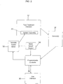
Fig. 3 is a flowchart of a first method in accordance with the present disclosure. -
Fig. 4 is a flowchart of a second method in accordance with the present disclosure. - The embodiments disclosed herein are for the purpose of providing an exemplary description of the present subject matter. They are, however, only exemplary, and the present subject matter may be embodied in various forms. Therefore, specific details disclosed herein are not to be interpreted as limiting the subject matter as defined in the accompanying claims.
- As illustrated in
Fig. 1 , anirradiation device 10 includes afluid treatment chamber 12 configured to receive abiological fluid container 14,fluid treatment chamber 12 having opposing first and second sides.Container 14 is suitable for irradiation by light of a selected wavelength. By "suitable for irradiation", it is meant that the walls of the container are sufficiently translucent to light of the selected wavelength. In treatments using UVA light, for example, container walls made of ethylene vinyl acetate (EVA) are suitable. - As illustrated in
Figs. 1 and2 ,device 10 also includes at least onelight source 20 disposed adjacent at least one of the first and second sides of thefluid treatment chamber 12.Light source 20 may include, for example, afirst array 22 with a plurality oflight sources 24 disposed on the first side of thefluid treatment chamber 12 and asecond array 26 with a plurality of light sources 28 disposed on the second side 18 offluid treatment chamber 12. According to an embodiment of the present disclosure,light sources 26, 28 are similar in structure and operation, and provide electromagnetic radiation in the ultraviolet portion of the spectrum (e.g., UVA). An alternative device is described inU.S. Patent No. 7,433,030 , the contents of which are incorporated by reference herein in its entirety. - As illustrated schematically in
Fig. 2 ,device 10 includes anagitator assembly 30 coupled tofluid treatment chamber 12 to move at least a part offluid treatment chamber 12 with an oscillatory motion. Theagitator assembly 30 may include amotor 32 in combination with a linkage (such as a rotating cam), the linkage coupling the motor tofluid treatment chamber 12. An embodiment of an agitator assembly is described in the afore-mentionedU.S. Patent No. 7,433,030 , which has been incorporated herein. By way of example, theagitator assembly 30 may causefluid treatment chamber 12, or at leastbiological fluid container 14 disposed influid treatment chamber 12, to move in an oscillatory fashion over a distance of 2.54 cm (1 inch). Optionally, amotor speed sensor 34 may be associated with themotor 32 for more accurately controlling the speed of the motor. - One or more sensors 38 (e.g., one or more of a UV sensor, a hematocrit sensor, a volume or weight detector or scale, a viscosity detector, a temperature sensor, an air detector, and a density detector) are disposed within the fluid treatment chamber for measuring a condition of the biological fluid in the
fluid container 14. Preferably, thesensors 38 are mounted within the fluid treatment chamber in proximity to the fluid. According to different embodiments, asingle sensor 38 may be provided, or a plurality ofsensors 38 may be provided to measure the various sensed conditions. - In one embodiment the
sensor 38 is a one or more light energy sensors (e.g., UV sensor ML8511-00FCZ05B from Rohm Semiconductor) that is disposed within the fluid treatment chamber for measuring the amount of light energy to which thefluid container 14 is subjected. Preferably, the light energy sensors are mounted within the fluid treatment chamber in proximity to the fluid container so as to more accurately measure the light energy reaching thefluid container 14. According to different embodiments, asingle sensor 38 may be provided, or a plurality ofsensors 38 may be provided. -
Irradiation device 10 also includes a user interface 36 (Figs.1 and2 ) and a controller 39 (Fig. 2 ). For the purposes of controlling the rate of oscillation of thefluid treatment chamber 12,controller 39 is coupled to theuser interface 36, thesensors 38, and thevariable speed motor 32 andmotor speed sensor 34.Controller 39 may be coupled directly, or through other intermediary equipment, such as signal processing equipment in the case of thesensors motor 32,sensors interface 36 may have their own power sources, or they may share a power source with, or be powered through, thecontroller 39. -
Device 10 may also include ahousing 40 in whichfluid treatment chamber 12 is defined, and in whichlight source 20,agitator 30,motor 32, andsensors Controller 39 may also be disposed inhousing 40, while theuser interface 36 may be disposed on or outside thehousing 40 so as to be readily accessible to the operator. WhileFig. 1 illustrates an embodiment ofhousing 40 including alid 42 that may be moved pivotally relative to a base 44 to openhousing 40 and permit access tofluid treatment chamber 12, it will be recognized thathousing 40 may instead include a sliding drawer that permits access tofluid treatment chamber 12. Details as to other features that may be incorporated in theirradiation device 10 are described and shown inUSSN 14/810,058, filed July 27, 2015, published February 2, 2017, asUS 2017/0029776 , the contents of which is incorporated by reference herein in its entirety. - While
controller 39 may take the form of one or more electrical components or circuits,controller 39 comprises a processor and an associated memory according to one embodiment. According to such an embodiment, the processor may be programmed to carry out any of the actions thatcontroller 39 is described as being configured to perform below. The instructions by which the processor is programmed may be stored on the memory associated with the processor, which memory may include one or more tangible non-transitory computer readable memories, having computer executable instructions stored thereon, which when executed by the processor, may cause the one or more processors to carry out one or more actions. - As an example, the
controller 38 may be programmed to carry out the following embodiment of a method of operatingdevice 10, as explained with reference toFigs. 1-3 . The method may begin with a determination whether the irradiation cycle should be initiated. Afluid container 14 containing a biological fluid may be placed by an operator in thefluid treatment chamber 12 and thelid 42 closed (step 100). For example,controller 39 may be coupled to a sensor disposed on housing, the sensor generating a signal when abiological fluid container 14 has been disposed intreatment chamber 12, and in particular intray 50. Alternatively, thecontroller 39 may be coupled to an input device, such as a keypad, that the user operates after biologicalfluid container 14 has been disposed intreatment chamber 12. In either event,controller 39 continues to monitor for a signal representative of the fact that the cycle should be initiated until such time as the signal is received. - A total amount of light energy to which the container is to be subjected during the irradiation cycle and/or an initial oscillation rate may be either preprogrammed into the controller or input by the operator through the user interface 36 (step 102). The irradiation cycle may then be initiated, with the
light sources 20 being activated (step 104), thereby illuminating biologicalfluid container 14 influid treatment chamber 12. Thefluid container 14 is oscillated by activating the agitator at the initial rate (which for some applications may be 0.0 cps (cycles per second))(step 106), thereby agitating biological fluid container 14 (if the initial rate is greater than 0.0 cps) whilebiological fluid container 14 is illuminated. WhileFig. 3 indicates that activation of the light sources (step 104) is initiated before oscillation of the treatment chamber (step 106), this need not be the case: oscillation of the fluid treatment container may precede illumination, or the two may be initiated as approximately the same time (i.e., "simultaneously"). - In a first example, the
sensors 38 are light sensors. Then, at time, t1, the method continues withcontroller 39checking sensors 38 to determine an initial value for the light energy, J0, emitted by the light sources 20 (step 108). t1 may coincide with the initiation of the irradiation cycle, or may be at some time interval thereafter. After a period of time, Δt, thecontroller 39 checks the sensors again to determine the current value for the light energy, Jt1, emitted by the light sources 20 (step 110). Thecontroller 39 then compares the initial light energy value, J0, and the light energy value at time t1, Jt1, to obtain the difference, ΔJ (step 112). If the absolute value of ΔJ is greater than 0.0 (or some other predetermined amount), thecontroller 39 will then determine the new oscillation rate (step 114), and adjust the rate of oscillation of theagitator 30 by increasing or decreasing the speed of themotor 32 to oscillate the fluid container at the new rate (step 116). - By way of example, the irradiation cycle may be commenced with an initial oscillation rate (e.g., 0.00 cps) and then after an interval of time (at t2) automatically oscillated a second rate, without regard to the instantaneous light energy value. Then, after a further period of time (at t1), the instantaneous light energy value is determined and compared to the initial light energy value to obtain the difference, and a new oscillation rate determined based thereon. Such a protocol could result in reduced treatment time, by agitating the container at a faster rate near the end of the irradiation cycle to prevent over exposure and to move previously untreated cells closer to the surface of the container to increase their exposure to light energy. Other oscillation protocols may be used that are either pre-programed into the controller, or are input by the operator at the time of use.
- For example, if Jt1 is greater than Jo, (i.e., ΔJ is greater than 0.0), then the controller will operate to increase the rate of oscillation. If Jt1 is less than Jo, (i.e., ΔJ is less than 0.0), then the controller will operate to decrease the rate of oscillation. The controller may utilize signals from the
motor speed sensor 34 to insure that the motor speed has been adjusted appropriately obtain the new oscillation rate. Under certain circumstances, a maximum rate of oscillation to which the container may be subjected can be pre-programmed into the controller or input into the controller by the operator. Further, it may be desirable that the absolute value of ΔJ be greater than a pre-determined, or an empirically-determined amount greater than 0.0, where an amount of less than the pre-determined amount could be attributable to system noise, before the oscillation rate is varied. - The steps of obtaining a signal indicative of a sensed condition and comparing it to the pre-determined value as described above (i.e., steps 108-116) are repeated at a time interval Δt throughout the irradiation cycle, and the oscillation rate is adjusted accordingly, until such time as the total amount of light energy to be delivered to the container, as either determined by the controller or input by the operator, has been achieved. Preferably, the controller determines a cumulative total of the light energy received by the container during the irradiation cycle, and then automatically deactivates the light sources once the total equals the desired amount.
- In a second example, in addition to the sensor(s) 38 being a light sensor, the
sensors 38 could be one or more of a sensor for sensing the hematocrit of the biological fluid, the weight of the biological fluid, the volume of the biological fluid, the density of the biological fluid, and the temperature of the biological fluid, and the volume of air in the container. In such circumstances the programmable controller is pre-programmed with a pre-determined standard or base-line value for each of the different sensed conditions, with the predetermined values being determined empirically. - For example, the base-line values are those that by experimentation are shown to provide for the optimal mixing of the biological fluid within the container. The base-line values for the hematocrit may be approximately 2%, the temperature approximately 22°C, the volume of biological fluid approximately 300ml, and the volume of air in the container approximately 3 ml, or less. From experiments conducted under these conditions, the base-line values for each of the other sensed conditions can be established.
- With reference to
Fig. 4 ,steps Fig. 3 . Then controller will receive a signal from one or more sensors indicative of the various sensed conditions (step 108a), compare the signal to the pre-determined base-line value for the particular sensed condition (step 112a), determine the new oscillation rate based on the sensed condition (step 114a) and the oscillation rate accordingly (Step 116a). - If the sensed condition is the energy of the light emitted by the light sources, the oscillation rate is varied as described above. If the sensed condition is the hematocrit of the biological fluid, the oscillation rate is increased if the hematocrit is higher than the predetermined value and decreased if the hematocrit is less than the predetermined value. If the sensed condition is the volume or weight of the biological fluid, the oscillation rate is increased if the volume or weight is higher than the predetermined value and decreased if the volume or weight is less than the predetermined value. If the sensed condition is the viscosity of the biological fluid, the oscillation rate is increased if the viscosity is higher than the predetermined value and decreased if the viscosity is less than the predetermined value. If the sensed condition is the temperature of the biological fluid, the oscillation rate is increased if the temperature is higher than the predetermined value and decreased if the temperature is less than the predetermined value. If the sensed condition is the volume of air in the container, the oscillation rate is decreases if the volume of air is higher than the predetermined value and increased if the volume of air is less than the predetermined value. If the sensed condition is the density of the biological fluid, the oscillation rate is increased if the density is higher than the predetermined value and decreased if the density is less than the predetermined value.
- The effect of the sensed conditions on the rate of oscillation can be additive. For example in the light energy is greater than -0-, the oscillation rate will be increased by a set amount and if, simultaneously, the viscosity is lower than the predetermined value, the oscillation rate will be decreased by a set amount. The two changes for the oscillation rate will be added together to result in the net change in oscillation rate.
- It should be noted that while the temperature and viscosity can vary over the course of a procedure, and thus are time sensitive, the volume of the biological fluid, the hematocrit, and the volume of air in the treatment container should remain essentially constant and thus will be measured at only one point in time over the course of the procedure, resulting in an initial, one-time adjustment to the oscillation rate based thereon.
- As noted above, the irradiation cycle may be commenced with an initial oscillation rate (e.g., 0.00 cps) and then after an interval of time automatically oscillated a second rate, without regard to the instantaneous light energy value. Then, after a further period of time, the instantaneous light energy value is determined and compared to the initial light energy value to obtain the difference, and a new oscillation rate determined based thereon. Further, the steps of obtaining a signal indicative of a sensed condition and comparing it to the pre-determined value as described above (i.e., steps 108a-116a) are repeated periodically throughout the irradiation cycle, and the oscillation rate is adjusted accordingly, until such time as the total amount of light energy to be delivered to the container, as either determined by the controller or input by the operator, has been achieved.
- In addition, the controller can be configured to accelerate and decelerate the fluid treatment chamber at a controlled rate to segregate within the fluid container the different cellular components of the biological fluid being treated based on the mass or density of the cellular components.
- To the extent that the mass or density of the cellular components is affected by degree to which they have been irradiated, the cellular components that have received a lower dosage of light energy can be migrated to a region of the fluid container where a greater dosage can be received, e.g., adjacent the walls of the container to receive a higher dose, while the cellular components that have received a higher dosage are displaced to the interior of the container to receive a lesser dose. Thus, a more even dosage of all the cellular components may be obtained.
- Alternatively, the cellular components that are segregated based their weight or density can be migrated to a portion of the container that facilitates their selective extraction (e.g., adjacent an extraction port that is integral with the container).
- Further, if the controller senses an unevenness of the intensity of the light being emitted the oscillation rate of the fluid treatment container can be accelerated/decelerated to migrate the cellular components to a location within the fluid treatment container that is receiving the higher intensity light.
- Without limiting any of the foregoing, the disclosed device, method and system may include one or more of the aspects set forth below.
- In a first aspect, a method for treating a biological fluid within a container by subjecting the container to light is provided that uses an apparatus including a fluid treatment chamber for receiving the container of biological fluid, an agitation assembly for oscillating the container of biological fluid within the fluid treatment chamber including a variable-speed motor, one or more light sources in proximity to the container of biological fluid when placed within the fluid treatment chamber, and one or more sensors for sensing one or more conditions of the biological fluid within the container, such as the energy of the light emitted by the one or more light sources.
- The method comprises: placing the container of biological fluid in the fluid treatment chamber; selecting an initial oscillation rate for oscillating the container of biological fluid within the fluid treatment chamber; oscillating the container of biological fluid at the initial oscillation rate; activating the one or more light sources; sensing the one or more conditions of the biological fluid, and varying the oscillation rate accordingly. In one example, if the conditioned sensed is the energy of the light emitted by the one or more light sources upon or after activation to obtain an initial light energy value Jo; after an interval of time t1, sensing the energy of the light emitted by the one or more light sources to obtain a light energy value Jt1; determining the difference ΔJ between Jo and Jt1; and varying the speed of the motor to adjust the oscillation rate of the container of biological fluid based on ΔJ.
- In a related aspect, a system for treating a biological fluid within a container by subjecting the container to light is provided comprising a fluid treatment chamber for receiving the container of biological fluid; an agitation assembly for oscillating the container of biological fluid within the fluid treatment chamber including a variable speed motor; one or more light sources in proximity to the fluid treatment chamber; one or more sensors for sensing one or more conditions of the biological fluid in the container, and a programmable controller. For example, the sensor may be a light sensor for sensing the energy of the light emitted by the one or more light sources.
- The programmable controller is further configured to operate the variable speed motor to oscillate the container of biological fluid within the fluid treatment chamber at an initial oscillation rate; activate the one or more light sources; measure the one or more conditions of the biological fluid, and varying the oscillation rate accordingly. In one example, if the conditioned sensed is the energy of the light emitted by the one or more light sources upon or after activation to obtain an initial light energy value Jo; after an interval of time t1, measure the energy of the light emitted by the one or more light sources to obtain a light energy value Jt1; determine the difference ΔJ between JO and Jt1; and vary the speed of the motor to adjust the oscillation rate of the container of biological fluid within the fluid treatment chamber based on ΔJ.
- In another aspect, the system and method provide for determining a total light energy to which the container is to be subjected; determining a cumulative light energy to which the container has been subjected; comparing the cumulative light energy to the pre-determined total light energy; and deactivating the light sources and the agitation assembly once the cumulative light energy equals or exceeds the pre-determined total light energy.
- In a further aspect, the system and method provide for determining on a continuous basis the cumulative amount of light energy to which the container is subjected.
- It will be understood that the embodiments described above are illustrative of some of the applications of the principles of the present subject matter. Numerous modifications may be made by those skilled in the art without departing from the spirit and scope of the claimed subject matter, including those combinations of features that are individually disclosed or claimed herein. For these reasons, the scope hereof is not limited to the above description, but is set forth in the following claims.
Claims (15)
- The method for treating a biological fluid within a container, the biological fluid having a hematocrit, volume, weight, viscosity, density, and temperature and the container holding a volume of air, by subjecting the container to light using an apparatus including: i) a fluid treatment chamber for receiving the container of biological fluid, ii) an agitation assembly for oscillating the container of biological fluid within the fluid treatment chamber including a variable-speed motor, iii) one or more light sources in proximity to the container of biological fluid when placed within the fluid treatment chamber, and iv) one or more sensors for sensing a condition of one or more of the energy of the light emitted by the one or more light sources, the hematocrit of the biological fluid, the weight of the biological fluid, the volume of the biological fluid , the density of the biological fluid, and the temperature of the biological fluid, and the volume of air in the container, the method comprising:a) placing the container of biological fluid in the fluid treatment chamber;b) selecting an initial oscillation rate for oscillating the container of biological fluid within the fluid treatment chamber;c) oscillating the container of biological fluid at the initial oscillation rate;d) activating the one or more light sources for emitting light energy;e) sensing one or more of the conditions of i) the energy of the light emitted by the one or more light sources, ii) the hematocrit of the biological fluid, iii) the weight of the biological fluid , iv) the volume of the biological fluid, v) the density of the biological fluid, vi) the temperature of the biological fluid, and vii) the volume of air in the container; andf) varying the speed of the motor to adjust the oscillation rate of the agitation assembly based on the sensed condition.
- The method of claim 1 wherein the sensed condition is energy of the light emitted by the one or more light sources, the method further comprising: i) sensing the energy of the light emitted by the one or more light sources upon or after activation to obtain an initial light energy value JO; ii) after an interval of time t1, sensing the energy of the light emitted by the one or more light sources to obtain a light energy value Jt1; iii) determining the difference ΔJ between Jo and Jt1; and iv) varying the speed of the motor to adjust the oscillation rate of the agitation assembly based on ΔJ.
- The method of claim 2 comprising increasing the oscillation rate if ΔJ is positive and decreasing the oscillation rate if ΔJ is negative.
- The method of claim 3 comprising increasing or decreasing the oscillation rate only if the absolute value of ΔJ is greater than a pre-determined amount.
- The method of any one of claims 2-4 wherein the initial oscillation rate is 0.00 cps.
- The method of claim 5 further comprising:selecting a second oscillation rate for oscillating the agitation assembly; andoscillating the agitation assembly at the second oscillation rate starting at a time t2, where t2 is less than t1.
- The method of any one of claims 1-6 further comprising:determining a total light energy to which the container is to be subjected;determining a cumulative light energy to which the container has been subjected;comparing the cumulative light energy to the pre-determined total light energy; anddeactivating the light sources and the agitation assembly once the cumulative light energy equals or exceeds the pre-determined total light energy.
- The method of any one of claims 1-7 wherein the sensed condition is compared to a pre-determined value for each sensed condition, and i) if the sensed condition is the hematocrit of the biological fluid, increasing the oscillation rate if the hematocrit is higher than the predetermined value and decreasing the oscillation rate if the hematocrit is less than the predetermined value; ii) if the sensed condition is the volume or weight of the biological fluid, increasing the oscillation rate if the volume or weight is higher than the predetermined value and decreasing the oscillation rate if the volume or weight is less than the predetermined value; iii) if the sensed condition is the viscosity of the biological fluid, increasing the oscillation rate if the viscosity is higher than the predetermined value and decreasing the oscillation rate if the viscosity is less than the predetermined value; iv) if the sensed condition is the temperature of the biological fluid, increasing the oscillation rate if the temperature is higher than the predetermined value and decreasing the oscillation rate if the temperature is less than the predetermined value; v) if the sensed condition is the volume of air in the container, decreasing the oscillation rate if the volume of air is higher than the predetermined value and increasing the oscillation rate it the volume of air is less than the predetermined value; and vi) if the sensed condition is the density of the biological fluid, increasing the oscillation rate if the density is higher than the predetermined value and decreasing the oscillation rate if the density is less than the predetermined value.
- A system for treating a biological fluid within a container, the biological fluid having a hematocrit, volume, weight, viscosity, density, and temperature and the container holding a volume of air, by subjecting the container to light, the system comprising:a fluid treatment chamber for receiving the container of biological fluid;an agitation assembly for oscillating the container of biological fluid within the fluid treatment chamber including a variable speed motor;one or more light sources for emitting light energy in proximity to the fluid treatment chamber;one or more sensors for sensing the condition of one or more of the energy of the light emitted by the one or more light sources, the hematocrit of the biological fluid, the weight of the biological fluid, the volume of the biological fluid, the density of the biological fluid, and the temperature of the biological fluid, and the volume of air in the container; anda programmable controller configured to:operate the variable speed motor to oscillate the agitation assembly at an initial oscillation rate;activate the one or more light sources;receive a signal from the one or more sensors indicative of the sensed condition; andvary the speed of the motor to adjust the oscillation rate of the agitation assembly based on the sensed condition.
- The system of claim 9 wherein the one or more sensors sense the condition of the energy of light emitted by the one or more light sources, and the programmable controller is further configured to i) receive a signal indicative of the energy of the light emitted by the one or more light sources upon or after activation to obtain an initial light energy value JO; ii) after an interval of time t1, measure the energy of the light emitted by the one or more light sources to obtain a light energy value Jt1; iii) determine the difference ΔJ between Jo and Jt1; iv) vary the speed of the motor to adjust the oscillation rate of the agitation assembly based on ΔJ; and v) increase the oscillation rate if ΔJ is positive and decrease the oscillation rate if ΔJ is negative.
- The system of claim 10 wherein the programmable controller is further configured to increase or decrease the oscillation rate only if the absolute value of ΔJ is greater than a pre-determined amount.
- The system of any one of claims 10-11 wherein the programmable controller is further configured to oscillate the container of biological fluid within the fluid treatment chamber at a pre-selected second oscillation rate starting at a time t2, where t2 is less than t1.
- The system of any one of claims 9-12 further comprising a motor speed sensor and the programmable controller is further configured to receive a signal from the motor speed sensor and to adjust the speed of the motor based thereon.
- The system of any one of claims 9-13 wherein the programmable controller is further configured to determine a total light energy to which the container is to be subjected;
determine a cumulative light energy to which the container has been subjected;
compare the cumulative light energy to the pre-determined total light energy; and
deactivate the light sources and the agitation assembly once the cumulative light energy equals or exceeds the pre-determined total light energy. - The system of any one of claims 9-14 wherein the programmable controller is pre-programmed with to a pre-determined value for each sensed condition, and is further configured to i) increase the oscillation rate if the hematocrit is higher than the predetermined value and decrease the oscillation rate if the hematocrit is less than the predetermined value; ii) increase the oscillation rate if the volume or weight is higher than the predetermined value and decrease the oscillation rate if the volume or weight is less than the predetermined value; iii) increase the oscillation rate if the viscosity is higher than the predetermined value and decrease the oscillation rate if the viscosity is less than the predetermined value; iv) increase the oscillation rate if the temperature is higher than the predetermined value and decrease the oscillation rate if the temperature is less than the predetermined value; v) decrease the oscillation rate if the volume of air is higher than the predetermined value and increase the oscillation rate it the volume of air is less than the predetermined value; and vi) increase the oscillation rate if the density is higher than the predetermined value and decrease the oscillation rate if the density is less than the predetermined value.
Applications Claiming Priority (2)
| Application Number | Priority Date | Filing Date | Title |
|---|---|---|---|
| US201662426643P | 2016-11-28 | 2016-11-28 | |
| US15/807,916 US10751433B2 (en) | 2016-11-28 | 2017-11-09 | Systems and methods for controlling an irradiation device |
Publications (2)
| Publication Number | Publication Date |
|---|---|
| EP3326666A1 true EP3326666A1 (en) | 2018-05-30 |
| EP3326666B1 EP3326666B1 (en) | 2021-08-18 |
Family
ID=60473367
Family Applications (1)
| Application Number | Title | Priority Date | Filing Date |
|---|---|---|---|
| EP17203683.2A Active EP3326666B1 (en) | 2016-11-28 | 2017-11-27 | Systems and methods for controlling an irradiation device |
Country Status (2)
| Country | Link |
|---|---|
| US (1) | US10751433B2 (en) |
| EP (1) | EP3326666B1 (en) |
Families Citing this family (14)
| Publication number | Priority date | Publication date | Assignee | Title |
|---|---|---|---|---|
| CA3187726A1 (en) | 2014-08-08 | 2016-02-11 | Fremon Scientific, Inc. | Smart bag used in sensing physiological and/or physical parameters of bags containing biological substance |
| US20180324900A1 (en) | 2017-05-04 | 2018-11-08 | Fremon Scientific, Inc. | Dry Heat Thawing of Biological Substances |
| CN116571191A (en) | 2017-12-29 | 2023-08-11 | 塞鲁斯公司 | Systems and methods for processing biological fluids |
| CA3090372A1 (en) * | 2018-02-02 | 2019-08-08 | Helmer, Inc. | Platelet agitator with discontinuous user input controls |
| WO2019217488A1 (en) | 2018-05-07 | 2019-11-14 | Fremon Scientific, Inc. | Thawing biological substances |
| EP3632484B1 (en) | 2018-10-04 | 2025-12-03 | Fenwal, Inc. | Systems for collecting samples in a photopheresis procedure |
| EP3666311B1 (en) | 2018-12-13 | 2026-02-04 | Fenwal, Inc. | Systems and methods for treating a biological fluid with light in the event of a bulb outage |
| EP3679968A3 (en) | 2019-01-10 | 2020-10-07 | Fenwal, Inc. | Systems and methods for verifying that a biological product is ready for treatment |
| US11883543B2 (en) | 2019-04-16 | 2024-01-30 | Fenwal, Inc. | Systems and methods for photoactivation of a biological fluid |
| CN114173842A (en) | 2019-06-22 | 2022-03-11 | 塞鲁斯公司 | Biological fluid treatment system |
| JP7571063B2 (en) | 2019-06-22 | 2024-10-22 | シーラス コーポレイション | Systems and methods for performing biological fluid treatment - Patents.com |
| WO2020264421A1 (en) | 2019-06-28 | 2020-12-30 | Cerus Corporation | System and methods for implementing a biological fluid treatment device |
| US12558469B2 (en) | 2021-08-06 | 2026-02-24 | Fenwal, Inc. | Systems and methods for converting an apheresis fluid processing circuit to single or double needle mode |
| US20240024559A1 (en) | 2022-07-22 | 2024-01-25 | Fenwal, Inc. | Blood processing and treatment systems and methods with procedure estimator |
Citations (5)
| Publication number | Priority date | Publication date | Assignee | Title |
|---|---|---|---|---|
| US20020008210A1 (en) * | 1998-07-15 | 2002-01-24 | Klaus Mausbach | Apparatus for the irradiation of a liquid |
| US7433030B2 (en) | 1999-06-03 | 2008-10-07 | Fenwal, Inc. | Apparatus, systems and methods for processing and treating a biological fluid with light |
| US8296071B2 (en) * | 2004-03-15 | 2012-10-23 | Terumo Bct Biotechnologies, Llc | Methods for uniformly treating biological samples with electromagnetic radiation |
| US9320817B2 (en) * | 2007-06-22 | 2016-04-26 | Maco Pharma S.A. | Irradiation apparatus for inactivating pathogens and/or leukocytes in a biological fluid and process |
| US20170029776A1 (en) | 2015-07-27 | 2017-02-02 | Fenwal, Inc. | Systems and methods for detecting fluid leaks using a non-contact sensor |
Family Cites Families (4)
| Publication number | Priority date | Publication date | Assignee | Title |
|---|---|---|---|---|
| US5385539A (en) * | 1992-06-30 | 1995-01-31 | Advanced Haemotechnologies | Apparatus for monitoring hematocrit levels of blood |
| US5951509A (en) | 1996-11-22 | 1999-09-14 | Therakos, Inc. | Blood product irradiation device incorporating agitation |
| US9452021B2 (en) * | 2013-08-02 | 2016-09-27 | All Cell Recovery LLC | Systems, methods, and apparatus for resuspending cells from surgical laundry |
| US20170028121A1 (en) | 2015-07-31 | 2017-02-02 | Fenwal, Inc. | Irradiation device for biological fluids |
-
2017
- 2017-11-09 US US15/807,916 patent/US10751433B2/en active Active
- 2017-11-27 EP EP17203683.2A patent/EP3326666B1/en active Active
Patent Citations (5)
| Publication number | Priority date | Publication date | Assignee | Title |
|---|---|---|---|---|
| US20020008210A1 (en) * | 1998-07-15 | 2002-01-24 | Klaus Mausbach | Apparatus for the irradiation of a liquid |
| US7433030B2 (en) | 1999-06-03 | 2008-10-07 | Fenwal, Inc. | Apparatus, systems and methods for processing and treating a biological fluid with light |
| US8296071B2 (en) * | 2004-03-15 | 2012-10-23 | Terumo Bct Biotechnologies, Llc | Methods for uniformly treating biological samples with electromagnetic radiation |
| US9320817B2 (en) * | 2007-06-22 | 2016-04-26 | Maco Pharma S.A. | Irradiation apparatus for inactivating pathogens and/or leukocytes in a biological fluid and process |
| US20170029776A1 (en) | 2015-07-27 | 2017-02-02 | Fenwal, Inc. | Systems and methods for detecting fluid leaks using a non-contact sensor |
Also Published As
| Publication number | Publication date |
|---|---|
| US20180147306A1 (en) | 2018-05-31 |
| EP3326666B1 (en) | 2021-08-18 |
| US10751433B2 (en) | 2020-08-25 |
Similar Documents
| Publication | Publication Date | Title |
|---|---|---|
| EP3326666B1 (en) | Systems and methods for controlling an irradiation device | |
| EP3328443B1 (en) | Systems and methods for detecting fluid leaks using a non-contact optical sensor | |
| EP3124053B1 (en) | Irradiation device for biological fluids | |
| US11504463B2 (en) | Systems and methods for verifying that a biological product is ready for treatment | |
| EP2953661B1 (en) | Method for delivering desired light dose to cells in a light attenuating medium | |
| CA2558260A1 (en) | Methods for uniformly treating biological samples with electromagnetic radiation | |
| CN102089011B (en) | Sub-cycle based aerosol disinfection system | |
| US20150196706A1 (en) | System and Method for Determining Irradiation Exposure Time with Irradiation Sensors During Extracorporeal Photopheresis | |
| US11577016B2 (en) | System and method for irradiating biological fluids | |
| EP3666311B1 (en) | Systems and methods for treating a biological fluid with light in the event of a bulb outage | |
| EP2111873B1 (en) | Ultrasonic treatment apparatus | |
| EP3552637B1 (en) | System for determining irradiation exposure time with light sensors during extracorporeal photopheresis | |
| KR20190061456A (en) | A Baby-Products Sterilizer Having Breast Pump | |
| US11883543B2 (en) | Systems and methods for photoactivation of a biological fluid | |
| US10927345B2 (en) | Activated platelet composition with tunable growth factor level | |
| US6719716B2 (en) | Hemo-aide | |
| RU2681143C1 (en) | Device, providing uniform measurement of blood cells in the devices for carrying out of extracorporal photochemotherapy | |
| US20180065864A1 (en) | Liquid treatment method and liquid treatment apparatus | |
| SE9101413L (en) | SYSTEM FOR TREATING A LIQUID IN A TREATMENT DEVICE AND THE USE OF THIS SYSTEM FOR TREATING A BIOLOGICAL LIQUID | |
| RU175013U1 (en) | DEVICE FOR QUICK DEFROSTING AND HEATING OF FROZEN MATERIAL | |
| CA3018505C (en) | Activated platelet composition with tunable growth factor level | |
| FI20195379A1 (en) | Wound care device | |
| JPH06205819A (en) | Sterilization apparatus | |
| CA3018505A1 (en) | Activated platelet composition with tunable growth factor level |
Legal Events
| Date | Code | Title | Description |
|---|---|---|---|
| PUAI | Public reference made under article 153(3) epc to a published international application that has entered the european phase |
Free format text: ORIGINAL CODE: 0009012 |
|
| STAA | Information on the status of an ep patent application or granted ep patent |
Free format text: STATUS: THE APPLICATION HAS BEEN PUBLISHED |
|
| AK | Designated contracting states |
Kind code of ref document: A1 Designated state(s): AL AT BE BG CH CY CZ DE DK EE ES FI FR GB GR HR HU IE IS IT LI LT LU LV MC MK MT NL NO PL PT RO RS SE SI SK SM TR |
|
| AX | Request for extension of the european patent |
Extension state: BA ME |
|
| STAA | Information on the status of an ep patent application or granted ep patent |
Free format text: STATUS: REQUEST FOR EXAMINATION WAS MADE |
|
| 17P | Request for examination filed |
Effective date: 20181105 |
|
| RBV | Designated contracting states (corrected) |
Designated state(s): AL AT BE BG CH CY CZ DE DK EE ES FI FR GB GR HR HU IE IS IT LI LT LU LV MC MK MT NL NO PL PT RO RS SE SI SK SM TR |
|
| STAA | Information on the status of an ep patent application or granted ep patent |
Free format text: STATUS: EXAMINATION IS IN PROGRESS |
|
| 17Q | First examination report despatched |
Effective date: 20190529 |
|
| GRAP | Despatch of communication of intention to grant a patent |
Free format text: ORIGINAL CODE: EPIDOSNIGR1 |
|
| STAA | Information on the status of an ep patent application or granted ep patent |
Free format text: STATUS: GRANT OF PATENT IS INTENDED |
|
| INTG | Intention to grant announced |
Effective date: 20210309 |
|
| GRAS | Grant fee paid |
Free format text: ORIGINAL CODE: EPIDOSNIGR3 |
|
| GRAA | (expected) grant |
Free format text: ORIGINAL CODE: 0009210 |
|
| STAA | Information on the status of an ep patent application or granted ep patent |
Free format text: STATUS: THE PATENT HAS BEEN GRANTED |
|
| AK | Designated contracting states |
Kind code of ref document: B1 Designated state(s): AL AT BE BG CH CY CZ DE DK EE ES FI FR GB GR HR HU IE IS IT LI LT LU LV MC MK MT NL NO PL PT RO RS SE SI SK SM TR |
|
| REG | Reference to a national code |
Ref country code: GB Ref legal event code: FG4D |
|
| REG | Reference to a national code |
Ref country code: CH Ref legal event code: EP |
|
| REG | Reference to a national code |
Ref country code: DE Ref legal event code: R096 Ref document number: 602017044190 Country of ref document: DE |
|
| REG | Reference to a national code |
Ref country code: IE Ref legal event code: FG4D Ref country code: AT Ref legal event code: REF Ref document number: 1421048 Country of ref document: AT Kind code of ref document: T Effective date: 20210915 |
|
| REG | Reference to a national code |
Ref country code: LT Ref legal event code: MG9D |
|
| REG | Reference to a national code |
Ref country code: NL Ref legal event code: MP Effective date: 20210818 |
|
| REG | Reference to a national code |
Ref country code: AT Ref legal event code: MK05 Ref document number: 1421048 Country of ref document: AT Kind code of ref document: T Effective date: 20210818 |
|
| PG25 | Lapsed in a contracting state [announced via postgrant information from national office to epo] |
Ref country code: SE Free format text: LAPSE BECAUSE OF FAILURE TO SUBMIT A TRANSLATION OF THE DESCRIPTION OR TO PAY THE FEE WITHIN THE PRESCRIBED TIME-LIMIT Effective date: 20210818 Ref country code: RS Free format text: LAPSE BECAUSE OF FAILURE TO SUBMIT A TRANSLATION OF THE DESCRIPTION OR TO PAY THE FEE WITHIN THE PRESCRIBED TIME-LIMIT Effective date: 20210818 Ref country code: HR Free format text: LAPSE BECAUSE OF FAILURE TO SUBMIT A TRANSLATION OF THE DESCRIPTION OR TO PAY THE FEE WITHIN THE PRESCRIBED TIME-LIMIT Effective date: 20210818 Ref country code: PT Free format text: LAPSE BECAUSE OF FAILURE TO SUBMIT A TRANSLATION OF THE DESCRIPTION OR TO PAY THE FEE WITHIN THE PRESCRIBED TIME-LIMIT Effective date: 20211220 Ref country code: NO Free format text: LAPSE BECAUSE OF FAILURE TO SUBMIT A TRANSLATION OF THE DESCRIPTION OR TO PAY THE FEE WITHIN THE PRESCRIBED TIME-LIMIT Effective date: 20211118 Ref country code: FI Free format text: LAPSE BECAUSE OF FAILURE TO SUBMIT A TRANSLATION OF THE DESCRIPTION OR TO PAY THE FEE WITHIN THE PRESCRIBED TIME-LIMIT Effective date: 20210818 Ref country code: ES Free format text: LAPSE BECAUSE OF FAILURE TO SUBMIT A TRANSLATION OF THE DESCRIPTION OR TO PAY THE FEE WITHIN THE PRESCRIBED TIME-LIMIT Effective date: 20210818 Ref country code: BG Free format text: LAPSE BECAUSE OF FAILURE TO SUBMIT A TRANSLATION OF THE DESCRIPTION OR TO PAY THE FEE WITHIN THE PRESCRIBED TIME-LIMIT Effective date: 20211118 Ref country code: AT Free format text: LAPSE BECAUSE OF FAILURE TO SUBMIT A TRANSLATION OF THE DESCRIPTION OR TO PAY THE FEE WITHIN THE PRESCRIBED TIME-LIMIT Effective date: 20210818 Ref country code: LT Free format text: LAPSE BECAUSE OF FAILURE TO SUBMIT A TRANSLATION OF THE DESCRIPTION OR TO PAY THE FEE WITHIN THE PRESCRIBED TIME-LIMIT Effective date: 20210818 |
|
| PG25 | Lapsed in a contracting state [announced via postgrant information from national office to epo] |
Ref country code: PL Free format text: LAPSE BECAUSE OF FAILURE TO SUBMIT A TRANSLATION OF THE DESCRIPTION OR TO PAY THE FEE WITHIN THE PRESCRIBED TIME-LIMIT Effective date: 20210818 Ref country code: LV Free format text: LAPSE BECAUSE OF FAILURE TO SUBMIT A TRANSLATION OF THE DESCRIPTION OR TO PAY THE FEE WITHIN THE PRESCRIBED TIME-LIMIT Effective date: 20210818 Ref country code: GR Free format text: LAPSE BECAUSE OF FAILURE TO SUBMIT A TRANSLATION OF THE DESCRIPTION OR TO PAY THE FEE WITHIN THE PRESCRIBED TIME-LIMIT Effective date: 20211119 |
|
| PG25 | Lapsed in a contracting state [announced via postgrant information from national office to epo] |
Ref country code: NL Free format text: LAPSE BECAUSE OF FAILURE TO SUBMIT A TRANSLATION OF THE DESCRIPTION OR TO PAY THE FEE WITHIN THE PRESCRIBED TIME-LIMIT Effective date: 20210818 |
|
| PG25 | Lapsed in a contracting state [announced via postgrant information from national office to epo] |
Ref country code: DK Free format text: LAPSE BECAUSE OF FAILURE TO SUBMIT A TRANSLATION OF THE DESCRIPTION OR TO PAY THE FEE WITHIN THE PRESCRIBED TIME-LIMIT Effective date: 20210818 |
|
| REG | Reference to a national code |
Ref country code: DE Ref legal event code: R097 Ref document number: 602017044190 Country of ref document: DE |
|
| PG25 | Lapsed in a contracting state [announced via postgrant information from national office to epo] |
Ref country code: SM Free format text: LAPSE BECAUSE OF FAILURE TO SUBMIT A TRANSLATION OF THE DESCRIPTION OR TO PAY THE FEE WITHIN THE PRESCRIBED TIME-LIMIT Effective date: 20210818 Ref country code: SK Free format text: LAPSE BECAUSE OF FAILURE TO SUBMIT A TRANSLATION OF THE DESCRIPTION OR TO PAY THE FEE WITHIN THE PRESCRIBED TIME-LIMIT Effective date: 20210818 Ref country code: RO Free format text: LAPSE BECAUSE OF FAILURE TO SUBMIT A TRANSLATION OF THE DESCRIPTION OR TO PAY THE FEE WITHIN THE PRESCRIBED TIME-LIMIT Effective date: 20210818 Ref country code: EE Free format text: LAPSE BECAUSE OF FAILURE TO SUBMIT A TRANSLATION OF THE DESCRIPTION OR TO PAY THE FEE WITHIN THE PRESCRIBED TIME-LIMIT Effective date: 20210818 Ref country code: CZ Free format text: LAPSE BECAUSE OF FAILURE TO SUBMIT A TRANSLATION OF THE DESCRIPTION OR TO PAY THE FEE WITHIN THE PRESCRIBED TIME-LIMIT Effective date: 20210818 Ref country code: AL Free format text: LAPSE BECAUSE OF FAILURE TO SUBMIT A TRANSLATION OF THE DESCRIPTION OR TO PAY THE FEE WITHIN THE PRESCRIBED TIME-LIMIT Effective date: 20210818 |
|
| PLBE | No opposition filed within time limit |
Free format text: ORIGINAL CODE: 0009261 |
|
| STAA | Information on the status of an ep patent application or granted ep patent |
Free format text: STATUS: NO OPPOSITION FILED WITHIN TIME LIMIT |
|
| PG25 | Lapsed in a contracting state [announced via postgrant information from national office to epo] |
Ref country code: MC Free format text: LAPSE BECAUSE OF FAILURE TO SUBMIT A TRANSLATION OF THE DESCRIPTION OR TO PAY THE FEE WITHIN THE PRESCRIBED TIME-LIMIT Effective date: 20210818 |
|
| REG | Reference to a national code |
Ref country code: CH Ref legal event code: PL |
|
| 26N | No opposition filed |
Effective date: 20220519 |
|
| PG25 | Lapsed in a contracting state [announced via postgrant information from national office to epo] |
Ref country code: LU Free format text: LAPSE BECAUSE OF NON-PAYMENT OF DUE FEES Effective date: 20211127 Ref country code: IT Free format text: LAPSE BECAUSE OF FAILURE TO SUBMIT A TRANSLATION OF THE DESCRIPTION OR TO PAY THE FEE WITHIN THE PRESCRIBED TIME-LIMIT Effective date: 20210818 Ref country code: BE Free format text: LAPSE BECAUSE OF NON-PAYMENT OF DUE FEES Effective date: 20211130 |
|
| REG | Reference to a national code |
Ref country code: BE Ref legal event code: MM Effective date: 20211130 |
|
| PG25 | Lapsed in a contracting state [announced via postgrant information from national office to epo] |
Ref country code: SI Free format text: LAPSE BECAUSE OF FAILURE TO SUBMIT A TRANSLATION OF THE DESCRIPTION OR TO PAY THE FEE WITHIN THE PRESCRIBED TIME-LIMIT Effective date: 20210818 |
|
| PG25 | Lapsed in a contracting state [announced via postgrant information from national office to epo] |
Ref country code: IE Free format text: LAPSE BECAUSE OF NON-PAYMENT OF DUE FEES Effective date: 20211127 |
|
| PG25 | Lapsed in a contracting state [announced via postgrant information from national office to epo] |
Ref country code: HU Free format text: LAPSE BECAUSE OF FAILURE TO SUBMIT A TRANSLATION OF THE DESCRIPTION OR TO PAY THE FEE WITHIN THE PRESCRIBED TIME-LIMIT; INVALID AB INITIO Effective date: 20171127 |
|
| P01 | Opt-out of the competence of the unified patent court (upc) registered |
Effective date: 20230515 |
|
| PG25 | Lapsed in a contracting state [announced via postgrant information from national office to epo] |
Ref country code: CY Free format text: LAPSE BECAUSE OF FAILURE TO SUBMIT A TRANSLATION OF THE DESCRIPTION OR TO PAY THE FEE WITHIN THE PRESCRIBED TIME-LIMIT Effective date: 20210818 |
|
| PG25 | Lapsed in a contracting state [announced via postgrant information from national office to epo] |
Ref country code: LI Free format text: LAPSE BECAUSE OF NON-PAYMENT OF DUE FEES Effective date: 20220701 Ref country code: CH Free format text: LAPSE BECAUSE OF NON-PAYMENT OF DUE FEES Effective date: 20220701 |
|
| PG25 | Lapsed in a contracting state [announced via postgrant information from national office to epo] |
Ref country code: MK Free format text: LAPSE BECAUSE OF FAILURE TO SUBMIT A TRANSLATION OF THE DESCRIPTION OR TO PAY THE FEE WITHIN THE PRESCRIBED TIME-LIMIT Effective date: 20210818 |
|
| PG25 | Lapsed in a contracting state [announced via postgrant information from national office to epo] |
Ref country code: TR Free format text: LAPSE BECAUSE OF FAILURE TO SUBMIT A TRANSLATION OF THE DESCRIPTION OR TO PAY THE FEE WITHIN THE PRESCRIBED TIME-LIMIT Effective date: 20210818 |
|
| PG25 | Lapsed in a contracting state [announced via postgrant information from national office to epo] |
Ref country code: MT Free format text: LAPSE BECAUSE OF FAILURE TO SUBMIT A TRANSLATION OF THE DESCRIPTION OR TO PAY THE FEE WITHIN THE PRESCRIBED TIME-LIMIT Effective date: 20210818 |
|
| PGFP | Annual fee paid to national office [announced via postgrant information from national office to epo] |
Ref country code: DE Payment date: 20241127 Year of fee payment: 8 |
|
| PGFP | Annual fee paid to national office [announced via postgrant information from national office to epo] |
Ref country code: GB Payment date: 20241127 Year of fee payment: 8 |
|
| PGFP | Annual fee paid to national office [announced via postgrant information from national office to epo] |
Ref country code: FR Payment date: 20241128 Year of fee payment: 8 |