EP3326528A1 - Gait analysis method and gait analysis system - Google Patents
Gait analysis method and gait analysis system Download PDFInfo
- Publication number
- EP3326528A1 EP3326528A1 EP16827854.7A EP16827854A EP3326528A1 EP 3326528 A1 EP3326528 A1 EP 3326528A1 EP 16827854 A EP16827854 A EP 16827854A EP 3326528 A1 EP3326528 A1 EP 3326528A1
- Authority
- EP
- European Patent Office
- Prior art keywords
- gait
- knee
- angle
- joint
- lower limb
- Prior art date
- Legal status (The legal status is an assumption and is not a legal conclusion. Google has not performed a legal analysis and makes no representation as to the accuracy of the status listed.)
- Granted
Links
Images










Classifications
-
- A—HUMAN NECESSITIES
- A61—MEDICAL OR VETERINARY SCIENCE; HYGIENE
- A61B—DIAGNOSIS; SURGERY; IDENTIFICATION
- A61B5/00—Measuring for diagnostic purposes; Identification of persons
- A61B5/103—Measuring devices for testing the shape, pattern, colour, size or movement of the body or parts thereof, for diagnostic purposes
- A61B5/11—Measuring movement of the entire body or parts thereof, e.g. head or hand tremor or mobility of a limb
- A61B5/112—Gait analysis
-
- A—HUMAN NECESSITIES
- A61—MEDICAL OR VETERINARY SCIENCE; HYGIENE
- A61B—DIAGNOSIS; SURGERY; IDENTIFICATION
- A61B5/00—Measuring for diagnostic purposes; Identification of persons
- A61B5/103—Measuring devices for testing the shape, pattern, colour, size or movement of the body or parts thereof, for diagnostic purposes
- A61B5/11—Measuring movement of the entire body or parts thereof, e.g. head or hand tremor or mobility of a limb
-
- A—HUMAN NECESSITIES
- A61—MEDICAL OR VETERINARY SCIENCE; HYGIENE
- A61B—DIAGNOSIS; SURGERY; IDENTIFICATION
- A61B5/00—Measuring for diagnostic purposes; Identification of persons
- A61B5/103—Measuring devices for testing the shape, pattern, colour, size or movement of the body or parts thereof, for diagnostic purposes
- A61B5/11—Measuring movement of the entire body or parts thereof, e.g. head or hand tremor or mobility of a limb
- A61B5/1116—Determining posture transitions
-
- A—HUMAN NECESSITIES
- A61—MEDICAL OR VETERINARY SCIENCE; HYGIENE
- A61B—DIAGNOSIS; SURGERY; IDENTIFICATION
- A61B5/00—Measuring for diagnostic purposes; Identification of persons
- A61B5/103—Measuring devices for testing the shape, pattern, colour, size or movement of the body or parts thereof, for diagnostic purposes
- A61B5/11—Measuring movement of the entire body or parts thereof, e.g. head or hand tremor or mobility of a limb
- A61B5/1121—Determining geometric values, e.g. centre of rotation or angular range of movement
- A61B5/1122—Determining geometric values, e.g. centre of rotation or angular range of movement of movement trajectories
-
- A—HUMAN NECESSITIES
- A61—MEDICAL OR VETERINARY SCIENCE; HYGIENE
- A61B—DIAGNOSIS; SURGERY; IDENTIFICATION
- A61B2562/00—Details of sensors; Constructional details of sensor housings or probes; Accessories for sensors
- A61B2562/02—Details of sensors specially adapted for in-vivo measurements
- A61B2562/0219—Inertial sensors, e.g. accelerometers, gyroscopes, tilt switches
Definitions
- the present invention relates to a gait analysis method and a gait analysis system using a body-worn sensor (also referred to as a "wearable sensor”), and particularly to a gait analysis method and a gait analysis system for calculating novel gait parameters useful for assessment of gait action.
- a body-worn sensor also referred to as a "wearable sensor”
- a gait analysis method and a gait analysis system for calculating novel gait parameters useful for assessment of gait action.
- Measurement of gait action is used to assess gait abilities, to plan treatments, and to assess treatments in a quantitative manner.
- examples of general systems for gait measurement with an instrument include an optical three-dimensional motion analysis system.
- the measurement environment is subject to restrictions, generally requiring a long time for analysis. Therefore, the optical three-dimensional motion analysis system is only used in the area of research, and it is difficult to say that the optical three-dimensional motion analysis system has been in clinical use sufficiently.
- Non-Patent Literature 1 In recent years, development and research of a gait measurement system capable of easier measurement has drawn attention. In the past, gait measurement using an acceleration sensor attached to a human body was proposed by Morris (Non-Patent Literature 1). Since then, measurement methods using a small-sized sensor, e.g., an acceleration sensor or an angular velocity sensor, have been researched (Non-Patent Literature 1 to 3). Thus, restrictions on measurement environments and a long required time, which were the problems with the conventional system, have been overcome, and it can be said that the practicability in clinical use has been increased.
- Non-Patent Literature 4 and 5 the inventors of the present application have pursued the development of a three-dimensional gait analysis using an acceleration sensor and an angular velocity sensor.
- the inventors of the present application have succeeded to measure a three-dimensional motion considering rotation of a joint with high precision by means of an analysis method using quaternion calculation (Non-Patent Literature 6).
- a gait analysis method of the present invention is characterized in that a tri-axial acceleration sensor and a tri-axial angular velocity sensor are attached to lower limb portions across at least one joint of joints constituting at least one of lower limbs of a subject, acceleration and angular velocity of each lower limb portion are respectively measured with the tri-axial acceleration sensor and the tri-axial angular velocity sensor during gait of the subject, the posture of each lower limb portion during the gait is calculated on the basis of the acceleration and the angular velocity measured, the lower limb portions in the calculated posture are coupled to one another to construct a three-dimensional model including a motion trajectory of the at least one joint, and an angle of an acceleration vector of the at least one joint at the time of heel contact with regard to the motion trajectory in a sagittal plane is calculated as a gait parameter.
- a gait analysis system of the present invention is characterized by including a tri-axial acceleration sensor and a tri-axial angular velocity sensor attached to lower limb portions across at least one joint of joints constituting at least one of lower limbs of a subject to respectively measure acceleration and angular velocity of each lower limb portion during gait of the subject, a model construction means for calculating the posture of each lower limb portion during the gait on the basis of the acceleration and the angular velocity measured and constructing a three-dimensional model including a motion trajectory of the at least one joint by coupling the lower limb portions in the calculated posture to one another, and a gait parameter calculation means for calculating an angle of an acceleration vector of the at least one joint at the time of heel contact with regard to the motion trajectory in a sagittal plane as a gait parameter.
- a three-dimensional model including a motion trajectory of at least one joint is constructed on the basis of acceleration data and angular velocity data of each lower limb portion during gait of a subject, and an angle formed by the motion trajectory and an acceleration vector of a joint at the time of heel contact is calculated, enabling determination of novel gait parameters useful for gait analysis.
- the at least one joint may be a knee joint.
- the three-dimensional model including the motion trajectory of at least one joint may be constructed with respect to each of right and left lower limbs of the subject.
- approximation straight lines may be formed with respect to the motion trajectories of right and left joints in a horizontal plane, and an angle formed between the approximation straight lines may be calculated as a gait parameter.
- a Lissajous figure of a joint may be created from a three-dimensional model, and a gait parameter may be calculated on the basis of the Lissajous figure.
- the gait analysis system of the present invention may be configured such that the tri-axial acceleration sensor and the tri-axial acceleration sensor are attached to the right and left lower limbs of a subject, the gait parameter calculation means forms approximation straight lines with respect to the motion trajectories of the right and left joints in a horizontal plane, and calculates an angle formed between the approximation straight lines as a gait parameter.
- the gait analysis system of the present invention may be configured such that the parameter calculation means creates a Lissajous figure of a joint from a three-dimensional model and calculates a gait parameter on the basis of the Lissajous figure.
- Fig. 1 there are three fundamental planes of a body motion as described below.
- the body motion can be expressed with reference to an axis, not a plane. This is defined as follows:
- a motion of a lower limb joint and an average range of motion of a joint of a healthy person are described.
- a hip joint is a three-degree-of-freedom joint that enables flexion and extension motions, adduction and abduction motions, and internal rotation and external rotation motions.
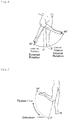
- Fig. 2 illustrates a direction of flexion and extension motions and a range of motion of a hip joint.
- a direction in which a leg is swung forward is the flexion direction.
- Fig. 3 illustrates a direction of adduction and abduction motions and a range of motion of a hip joint. It is a rotation in the coronal plane in which a direction in which a foot approaches the median axis is the adduction and a direction in which a foot moves away from the median axis is the abduction.
- Fig. 4 illustrates a direction of internal rotation and external rotation motions and a range of motion of a hip joint. It is a rotation about an axis of a thigh.
- a direction in which the point approaches the fundamental sagittal plane is the internal rotation and a direction in which the point moves away from the fundamental sagittal plane is the external rotation.
- Fig. 5 illustrates a direction of flexion and extension and a range of motion.
- a direction in which a foot approaches buttocks is the flexion direction and a direction in which a foot moves away from buttocks is the extension direction.
- a knee joint is often considered a hinge joint.
- the motion of a knee joint is not limited to flexion and extension, but the movable motion can be expanded in the adduction and abduction directions or in the internal rotation and external rotation directions due to impairment, e.g., damage to an anterior cruciate ligament.
- the motion of a knee joint is generally treated three-dimensionally. Therefore, according to the present invention, a knee joint is treated as a spheroidal joint.
- a direction in which a knee joint has varus deformity (bowleg) is the adduction direction, and a direction in which a knee joint has valgus deformity (knock knee) is the abduction direction.
- a direction in which the front surface of a shank faces inward relative to the thigh is the internal rotation direction, and a direction in which the front surface of a shank faces outward is the external rotation direction.
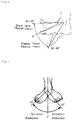
- FIG. 6 illustrates a direction of plantar flexion and dorsi flexion, and a range of motion. A direction in which a toe is pressed down toward the sole is the plantar flexion direction, and an opposite direction is the dorsi flexion direction.
- Fig. 7 illustrates a direction of adduction and abduction and a range of motion. A direction in which a toe approaches the median axis is the adduction, and a direction in which a toe moves away from the median axis is the abduction.
- the gait cycle is divided into a stance phase and a swing phase.
- the stance phase indicates a phase from the heel contact to the toe off, i.e., a state in which the foot is on the ground.
- the swing phase is a phase from the toe off to the heel contact, i.e., a state in which the foot is off the ground.
- the stance phase and the swing phase of the gait cycle account for about 60% and about 40%, respectively.
- a direction having a vector is illustrated.
- a rotation about the axis of the vector does not provide any apparent change.
- an orientation having a coordinate system is illustrated. Even when a rotation is made about one basic axis therefrom, the rotation can be observed according to a change of the direction of another basic axis.
- the relationship between the orientations of two coordinate systems can be expressed by conversion by means of a unit matrix E
- the relationship between the two coordinate systems is said to be in an "identical state".
- the corresponding basic axes of the two coordinate systems are parallel to each other.
- An angular displacement from the identical state is called the orientation.
- the angular displacement indicates a quantity varying with rotation.
- a general method of expressing the orientation in the field of mathematics is a matrix.
- a coordinate system O-XYZ and a coordinate system O'-xyz illustrated in Fig. 9 are considered in a three-dimensional space.
- the coordinate system O'-xyz can freely move in the coordinate system O-XYZ.
- the orientation of the coordinate system O'-xyz, which is observed from the coordinate system O-XYZ is determined.
- the coordinate system O'-xyz starts in the identical state with respect to the coordinate system O-XYZ, and predetermined rotation operation is performed.
- the orientation of the coordinate system O'-xyz as of the present time is illustrated.
- basic vectors e x , e y , e z of O'-xyz are known to be vectors of the coordinate system O-XYZ, a rotation matrix indicated in Equation (1) is determined from these three vectors.
- Equation (1) is an orthogonal matrix
- inverse conversion is determined by transposition of it.
- Euler angles As a general method of expressing the motion of a body, there is a concept called Euler angles. In the field of orthopedic surgery or biomechanics, the Euler angles are used with respect to the motion of a three-degree-of-freedom joint, e.g., a shoulder joint or a hip joint. The Euler angles are less used for those modeled as a joint with only flexion and extension motions, e.g., a knee joint.
- the Euler angles are named after Leonhard Euler, who proved that any orientation can be expressed by rotation of three different axes. There are many definitions of the Euler angles depending on the combination of an order of rotation. Three parameters expressing the amount of rotation depend on an order of rotation. For correct expression of the orientation, it is necessary to describe the definitions of the Euler angles to be used.
- the z-y-x Euler angles general Euler angles, are introduced in conjunction with Fig. 10 .
- a coordinate system in the identical state with the coordinate system O-xyz described in (6) above is considered.
- rotation at an angle ⁇ about the z axis is performed. This is called a "heading angle”.
- rotation at an angle ⁇ about the y axis after the rotation is performed. This is called a "pitch angle”.
- rotation at an angle ⁇ about the x axis after the above rotation is performed. This is called a "bank angle”.
- Equation (3) indicates a rotation matrix of the z-y-x Euler angles
- Equation (3) symbols sin and cos are abbreviated as s and c, respectively.
- Symbols R x , R y and R z are as described in Equations (4) to (6).
- the rotations of the Euler angles in the case of inverse conversion, i.e., when rotation is performed in an order of x-y-z axes, are called a roll angle, a pitch angle, and a yaw angle, respectively. These are called Cardan angles, which are most frequently used in biomechanics.
- the number of parameters minimally required for expression of a three-dimensional angular displacement is three.
- the Euler angles are expressed by minimally required three angles.
- such parameters are directly linked to angle data and are therefore very intuitive.
- the Euler angles are merely a forward kinematical "orientation expressing method", but are not a calculation method. Calculation is somewhat troublesome when an orientation indicated by certain Euler angles is changed to an orientation indicated by different Euler angles.
- the Euler angles are not a preferable method because of conditional processing with regard to singularities and an increase in number of times of calculation as indicated by Equation (3).
- the quaternion is a type of "hypercomplex numbers", which is an extension of complex numbers. In recent years, the quaternion is applied to the field of 3D computer graphics and spacecraft attitude control.
- the quaternion is formed of one scalar element and one vector element.
- methods of expressing a quaternion there are various methods including a method of expressing a quaternion as a matrix and a method of expressing a quaternion using an exponential map.
- the expression described below is used.
- Symbols W, X, Y and Z are quaternion parameters. Similar to V, symbols X, Y and Z can be expressed as vectors. When quaternions are used in an orientation expressing method, the quaternions are easier to understand as they are expressed as vectors. Symbols i, j and k are called quaternion units that are similar in property to imaginary numbers.
- the quaternion has a norm, which is defined in Equation (9) .
- the quaternion is a type of hypercomplex numbers. Therefore, similar to complex numbers, there is a concept called a conjugate quaternion, which is indicated by Equation (11).
- Equation (12) a product of the unit quaternions is indicated by Equation (12).
- Equation (13) A geometric significance of the quaternion is described.
- Equation (13) A geometric significance of the quaternion is described.
- Equation (13) A geometric significance of the quaternion is described.
- Equation (13) A geometric significance of the quaternion is described.
- Equation (13) A geometric significance of the quaternion is described.
- Equation (13) A geometric significance of the quaternion is described.
- n is a unit vector.
- a real component may be any value and here is zero for the sake of simplicity.
- the unit quaternions n and ⁇ used for rotation indicated in Equation (13) indicate a vector indicating an axis of rotation and the amount of rotation about the axis, respectively.
- the quaternions are used for computation of angular displacement.
- a gait analysis system and a gait analysis method measure acceleration and angular velocity of a body part during gait of a subject, estimates a lower limb posture on the basis of the measurement data, and calculates a gait parameter required for assessment of gait.
- a gait analysis system 1 includes sensor units 3 for measuring acceleration and angular velocity of a body part during gait, a processing device 5 for acquiring acceleration data and angular velocity data from the sensor units 3 and executing processing of calculating a parameter for gait assessment, and a monitor screen 7 for displaying results of gait assessment.
- Each sensor unit 3 is formed as one tri-axial acceleration sensor, one bi-axial angular velocity sensor, and one uni-axial angular velocity sensor are configured as a unit.
- the sensor unit 3 detects acceleration of perpendicular three axial directions and angular velocity about the axes.
- the acceleration sensor and the angular velocity sensor may not be configured as a unit.
- Each sensor unit 3 is configured to transmit acceleration data and angular velocity data detected by the acceleration sensor and the angular velocity sensor, respectively, to the processing device 5 in real time via wireless communication.
- Each sensor unit 3 includes a software timer. At the timing of measurement of acceleration and angular velocity with the internal sensors, a timer value is stored together. Thus, all the sensor units are synchronized.
- a sampling frequency is set to 100 Hz.
- Figs. 12(a) and (b) illustrate attachment positions and an attachment method for the sensor units 3 with respect to a subject (testee) at the time of data measurement.
- a total of seven sensor units 3 are attached to the pelvis, the right and left thighs, the right and left shanks, and the right and left feet, respectively.
- the sensor units 3 may be fixed in a predetermined position by being housed in pockets formed on sports tights or pockets formed on a sports band worn by a subject during gait.
- the sensor units 3 are not subjected to any particular limitation regarding fixing position, but may be arranged at any location on the aforementioned portions.
- the sensor unit 3 on the pelvis be fixed to the midpoint of the right and left posterior iliac crests, the sensor units 3 on the thighs be fixed to the quadriceps muscle middle portions, and the sensor units 3 on the shanks be attached to the inner sides of the front parts of the tibiae.
- the sensor units 3 on the feed can be fixed to the surfaces of shoes by means of a sports band or the like. However, it is preferable to avoid the vicinity of the metatarsal joint and to select proper locations to be free of influences by plantar and dorsi flexion.
- the directions of the sensor units 3 when fixed may be arbitrary because the directions are corrected by a method that will be described later.
- reference numeral 4 in the drawings indicates markers that will be described later.
- a three-dimensional wire-frame model such as that illustrated in Fig. 13 is constructed to express the posture of a body part during gait.
- This is an extension of a method of expressing a part of a body as a rigid body link model, and a plane is formed of wires.
- Parts expressed by wires are regarded as rigid bodies, which are called segments for the sake of convenience. Each of the segments is capable of independent motion.
- the lower limb model is formed of a total of seven segments: a pelvis segment, right and left thigh segments, right and left shank segments, and right and left foot segments. The details are described below.
- the pelvis segment is formed of six points: right and left anterior superior iliac spines, right and left posterior iliac crests, and right and left hip joint centers.
- the thigh segment is formed of four points: a hip joint center, a great trochanter, a medial knee joint space, and a lateral knee joint space.
- the shank segment is formed of a lateral condyle of tibia, a medial knee joint space, a lateral knee joint space, and an ankle joint center.
- the ankle joint center is a midpoint of the lateral malleolus and the medial malleolus.
- the ankle joint segment is formed of three points: an ankle joint center, a heel bone, and a toe.
- the construction of a wire-frame model requires body dimensions.
- the body dimensions measured at the time of gait measurement are described below.
- the body dimensions may be input with an input means, e.g., a keyboard connected to the processing device.
- the pelvis segment is modeled such that the pelvis segment has an average shape consistently and the size varies in proportion to the intertrochanteric distance.
- a sensor coordinate system for calculation and expression of gait postures, three types of coordinate systems: a sensor coordinate system, a ground coordinate system, and a segment coordinate system are used.
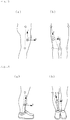
- a right thigh is taken as an example, and three coordinate systems are illustrated in Figs. 14(a) and (b) .
- the sensor coordinate system is indicated by reference symbol C sn
- the ground coordinate system is indicated by reference symbol C e
- the segment coordinate system is indicated by reference symbol C sg .
- the ground coordinate system is a stationary system for observation of motion, and is defined such that the z-axis is taken vertically upward and the x-axis is taken parallel to the initial sagittal-horizontal axis of a subject and anteriorly from the subject.
- the y-axis is taken to be perpendicular to both of them to form a right-handed system.
- Figs. 15(a) and (b) illustrate the definition of the coordinate system of the thigh segment.
- the z-axis is taken parallel to a line connecting the great trochanter and the lateral knee joint space, and the sagittal-horizontal axis (front direction, walking direction) is taken as the x-axis.
- Figs. 16(a) and (b) illustrate the definition of the coordinate system of the shank segment.
- the z-axis is taken parallel to a line connecting the knee joint center and the ankle joint center, and the sagittal-horizontal axis (front direction, walking direction) is taken as the x-axis.
- the knee joint center is a midpoint of the lateral knee joint space and the medial knee joint space
- the ankle joint center is a midpoint of the ankle joint lateral malleolus and the ankle joint medial malleolus.
- the coordinate systems of the pelvis segment and the foot segments are defined to correspond to the ground coordinate system in a standing posture.
- the standing posture is assumed, the toes are directed forward and the feet are aligned.
- the processing device 5 uses a personal computer, but may be anything insofar as it can acquire acceleration data and angular velocity data from the sensor units 3 and perform predetermined computation processing to indicate a predetermined gait parameter on the monitor screen 7 or output or record a predetermined gait parameter on a different device.
- the processing device 5 includes a data acquisition portion 11 for acquiring acceleration data and angular velocity data from each sensor unit 3, a sensor posture estimation portion 13 for estimating the posture (orientation) of the sensor coordinate system on the basis of the acceleration data and the angular velocity data of each body part, the acceleration data and the angular velocity data being acquired by the data acquisition portion 11, a segment posture computation portion 15 for computing the posture of each segment by converting the posture estimated by the sensor posture estimation portion 13 into the posture (orientation) of the segment coordinate system, a lower limb posture computation portion 17 for creating each segment on the basis of the posture of each segment computed by the segment posture computation portion 15 and body dimensions input and coupling the created segments in a predetermined posture so as to compute a lower limb posture (three-dimensional wire-frame model) during gait, and a gait parameter computation portion 19 for calculating a gait parameter on the basis of the lower limb posture computed by the lower limb posture computation portion 17.
- the data acquisition portion 11, the sensor posture estimation portion 13, the segment posture computation portion 15, and the lower limb posture computation portion 17 described above constitute the model construction means of the present invention.
- the aforementioned gait parameter computation portion 19 constitutes the gait parameter calculation means of the present invention.
- the sensor posture estimation portion 13 estimates the posture of the sensor during gait in the manner described below.
- Equation (15) the first term of the right-hand side indicates an initial posture (orientation), and the second term indicates an angular displacement from the initial posture.
- the initial posture is estimated through the use of the acceleration data obtained by the acceleration sensor.
- the angular displacement is estimated through the use of the angular velocity data obtained from the angular velocity sensor.
- the acceleration sensor detects a motion acceleration a and a gravitational acceleration g simultaneously.
- the acceleration sensor detects a gravitational acceleration component only.
- an angle formed by the vertical axis (gravity direction) and the detection axes of the acceleration sensor can be calculated from the proportion of the detection axes of the acceleration sensor and the vector sum.
- the heading angle of the aforementioned Euler angles at a time when a subject assumes the initial posture may be defined to be 0°.
- Symbol ⁇ indicates an angular velocity vector obtained from the detected acceleration of each axis of the angular sensor, and symbol ⁇ t s indicates a sampling period. They are substituted into the aforementioned Equation (13), and the result is described below.
- the sensor posture estimation portion 13 estimates the posture of the sensor units 3.
- the sensor units 3 are attached to body parts corresponding to the respective segments and measurement is performed to determine the posture of each body part (segment).
- the sensor units 3 it is difficult or impossible to attach the sensor units 3 such that the sensor coordinate system corresponds to the segment coordinate system. Therefore, for estimation of the motion of the segments, it is necessary that an experiment different from the gait experiment be performed to determine the relative postures between the sensor coordinate system and the segment coordinate system, and the posture of the sensor coordinate system be converted into the posture of the segment coordinate system.
- the sensor unit 3 and the segment exhibit a similar angular motion. Therefore, when the posture of the sensor unit 3 is determined, the posture of the segment can be determined as a result of rotation operation.
- the manner of determining the rotation matrix from the sensor coordinate system to the ground coordinate system is described.
- the acceleration data is measured when a subject is at rest in a standing posture or at rest in a seated posture.
- the standing posture is a state that a subject upstands on a horizontal ground where both toes are aligned as illustrated in Fig. 16 .
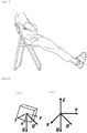
- the seated posture is as illustrated in Fig. 19 .
- the toes are also aligned in the seated posture.
- FIG. 20 The manner of determining the rotation matrix from the sensor coordinate system to the ground coordinate system on the basis of the above is described in conjunction with Fig. 20 .
- An arrow g positioned at the middle indicates the gravitational acceleration in the standing position, and an arrow g positioned on the right side indicates the gravitational acceleration in the seated position.
- the z-axis of the ground coordinate system is defined to be the direction opposite to that of the gravitational acceleration in the standing position.
- the y-axis is defined by a cross product of the gravitational acceleration in the standing position and the gravitational acceleration in the seated position.
- the x-axis is defined by a cross product of the y-axis and the z-axis.
- the basic vector of the ground coordinate system with respect to the sensor coordinate system can be acquired.
- the rotation from the ground coordinate system to the segment coordinate system provides the segment coordinate system with respect to the ground coordinate system from a front view photograph and a side view photograph in the standing posture as illustrated in Fig. 14 , and the rotation matrix from the ground coordinate system to the segment coordinate system can be obtained.
- the system of the present embodiment includes a filtering means.
- the data obtained by the angular velocity sensor includes noise. Because the noise is high frequency, the noise can be removed by a low-pass filter.
- the low-pass filter for example, a Butterworth filter of an IIR digital filter may be used. In this case, the cutoff frequency can be 12 Hz.
- the use of this filter results in generation of a phase delay, but the filtering processing with the same property is performed twice in total: one before the data and the other after the data to eliminate the phase delay.
- Fig. 21 illustrates results of the low-pass filter processing by comparing the states before and after the filtering processing.
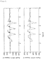
- the data obtained from the angular velocity sensor contain bias. This is described in conjunction with an angular velocity waveform at the time of gait measurement illustrated in Fig. 22 .
- the horizontal axis indicates the time elapsed from beginning of measurement, and the vertical axis indicates the angular velocity about the y-axis of the sensor arranged on the right thigh.
- the angular velocity sensor records a non-zero value as a detected value even at rest. This is a bias of the angular velocity.
- the method of calculating the angular displacement includes an integration element. Therefore, biases are accumulated during numerical integration, which directly leads to errors. Thus, it is necessary that the amount of bias be estimated and be subtracted from the original data before integration calculation.
- bias estimation methods There are various bias estimation methods.
- the mode of raw data is estimated to be bias.
- the gait parameter computation portion 19 calculates various types of parameters required for gait assessment from the lower limb posture computed by the lower limb posture computation portion with a predetermined program and the timings of the heel contact and the toe off.
- the timings of the heel contact and the toe off can easily be determined by means of an optical system or a floor reaction force gauge.
- only the acceleration and angular velocity data are used for detection. Specifically, as described below, the timing of the heel contact is detected from the angular velocity data of the shank, and the timing of the toe off is detected from the relative positions of the right and left toes.
- the angular velocity of the shank during gait is close to 0 degrees/second in the stance phase, and a relatively large angular velocity is generated in the swing phase because the shank is swung forward.
- the shank swung forward is slightly pulled backward. Therefore, the peak value of the angular velocity appears in the direction opposite to that of the swing phase. This peak position is used for detection of the heel contact.
- Fig. 24 illustrates a distance in walking direction from the original point (midpoint of the right and left hip joint centers) to the right toe. This is a graph indicating a standing state at rest at the onset and the beginning of gait at the point near 1.5 seconds.
- the gait begins, first, the right leg is swung forward, and the distance from the original point increases in a positive direction. The heel contact is made slightly after the positive peak position.
- the distance from the original point decreases, and subsequently the toe is shifted backward beyond the original point. Therefore, the distance from the original point increases in a negative direction.
- the toe off is made, and the right leg again begins to swing forward, and the distance from the original point starts increasing in the positive direction.
- the relative position of the toe is calculated from the lower limb posture obtained by the lower limb posture computation portion 17, and the timing at which the relative distance from the original point assumes the negative peak position is the timing of the toe off.
- gait parameters calculated by the gait parameter computation portion 19 from the lower limb posture computed by the lower limb posture computation portion 17 and the timings of the heel contact and the toe off are described below. These gait parameters are commonly used for diagnosis of a patient with knee osteoarthritis (knee OA), for example, in gait analysis through observation by a doctor or a physical therapist.
- the gait parameter computation portion 19 calculates two further novel gait parameters.
- the novel assessment parameters can be obtained through the use of a Lissajous figure.
- the Lissajous figure is a "plane figure obtained on an orthogonal coordinate as two simple harmonic motions are combined".
- the Lissajous figure indicates a motion trajectory of a joint or a gravity center position in the sagittal plane, the horizontal plane, or the coronal plane.
- the Lissajous figure currently, only the motion trajectory in the coronal plane is used, for example, in the field of gait research.
- gait is a motion involving movement, and therefore in the case of an optical system or the like, a motion trajectory in the sagittal plane or the horizontal plane does not draw a closed curve, but forms a single wave-like trajectory, which renders it difficult to handle.
- the gait analysis system including the property in which a lower limb posture is calculated as the midpoint of the right and left hip joint centers is used as the original point, and the Lissajous figure of each joint can be obtained as a closed curve in all the planes: the sagittal plane, the horizontal plane, and the coronal plane.
- the Lissajous figure is drawn by the gait parameter calculation portion 19.
- the first novel gait parameter is a knee acceleration vector direction.
- Fig. 25 illustrates motion trajectories of joints (great trochanter, knee joint, ankle joint) in the sagittal plane.
- the original point is the midpoint of the right and left hip joint centers, and the rightward direction in the plane of paper is the walking direction.
- the arrow line supplementary indicated on the motion trajectory of the knee joint indicates the acceleration vector at the time of the heel contact.
- the parameter calculation portion 19 calculates an angle ⁇ acc of the acceleration vector with regard to the knee joint trajectory as an assessment parameter.
- the other novel gait parameter is a trajectory angle in a knee joint horizontal plane.
- Fig. 26 illustrates motion trajectories of knee joints in the horizontal plane.
- the original point is the midpoint of the right and left hip joint centers, and the upward direction in the plane of paper is the walking direction.
- the left closed curve is the motion trajectory of the left knee joint
- the right closed curve is the motion trajectory of the right knee joint.
- straight lines extending substantially up and down in the motion trajectories are obtained as the motion trajectories are approximated to a straight line.
- the parameter calculation portion calculates an angle ⁇ xy formed by the two straight lines as an assessment parameter.
- Fig. 27 illustrates a method of data processing using the gait analysis system configured in the aforementioned manner.
- raw data obtained in a gait experiment passes through a low-pass filter and a high-pass filter.
- the initial posture and the angular displacement of each segment are calculated through the calculation of the posture of the sensor unit 3 during gait and the conversion of coordinate systems from the sensor coordinate system to the segment coordinate system.
- the calculation uses quaternions, and therefore in this stage the initial posture and the angular displacement are expressed in terms of quaternions.
- the mode is used to estimate an angular velocity bias. Therefore, the bias estimation precision depends on resolution. Accordingly, the angular displacement, a result of its integration, includes integration drift of estimation errors.
- each segment is created on the basis of body dimensions and the segments are coupled together to construct the lower limb posture during gait.
- the aforementioned various types of gait parameters can be calculated on the basis of the lower limb posture.
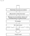
- a procedure of an experiment conducted is briefly illustrated in Fig. 28 .
- the seven sensor units 3 were attached to parts, and ten markers 4 (see Fig. 12 ) were attached to the right and left great trochanters, the medial and lateral knee joint spaces, ankle joint medial malleolus and lateral malleolus, respectively.
- body dimensions intertrochanteric distance, thigh length, shank length
- acceleration data for use in conversion of coordinate systems from the sensor coordinate system to the segment coordinate system was measured. In this case, the standing posture of a subject was photographed from the front side, the left side, and the right side.
- gait was measured (measurement of acceleration and angular velocity). Conditions of gait will be described later.
- the various types of gait parameters, the graphs, and the motion trajectories described above were obtained through analysis using a program on the basis of the acceleration and angular velocity data obtained by the measurement up to this point, and the photographs.
- the reproducibility of measurement indicates the following two meanings: reproducibility at a time when different measurers measure the same subject, and reproducibility at a time when the same subject is measured on different days (day-to-day reproducibility). Specifically, it is required that measurement can be done by any measurer and follow-up after treatment of a subject can be understood correctly.
- Table 1 Healthy group Knee OA group Average (Standard deviation) Average (Standard deviation) Age [years] 22.9 (0.8) 68.7 (4.1) Weight [kg] 69.1 (5.4) 54.2 (5.9) Height [m] 1.74 (0.05) 1.52 (0.05) BMI [kg/m 2 ] 23.0 (1.6) 23.5 (2.5) Thigh length [cm] 38.0 (2.3) 32.4 (2.7) Shank length [cm] 40.8 (1.6) 35.6 (1.7) Distance between the greater trochanters [cm] 35.6 (1.5) 34.5 (1.5)
- the gait measurement on the straight flat way started from a standing resting state illustrated in Fig. 16 .
- the subjects walked at given velocity and then again assumed a standing resting state.
- the gait measurement on the treadmill started from a standing resting state on the belt at rest.
- the belt velocity was gradually increased to 3 km per hour, and after gait at a steady velocity, the belt was again stopped, and the subjects assumed a standing state.
- the duration from the start to the end was consistently about 20 seconds.
- Measurers A 1st and B 1st two measurers separately conducted the same experiment on the same day to perform measurement on each subject.
- Measurer A performed the same trial on each subject about one week after the first measurement to again conduct measurement (indicated as Measurer A 2nd ). The measurement was performed once with respect to each gait condition and measurement condition, and a total of six measurement results were obtained per person.
- gait parameters For calculation of the gait parameters, which were measurement results, data excluding the beginning and the end of the gait was used. In the case of level ground gait, data including a total of four steps: two right steps and two left steps was used, and in the case of treadmill gait, data including a total of ten steps: five right steps and five left steps was used.
- the subjects of a gait measurement experiment on knee OA patients include ten medial knee OA patients.
- the averages and the standard deviations of age, weight, height, BMI, and body dimensions are indicated in Table 1 described above, and information regarding symptoms is indicated in Table 2.
- Table 2 Patient B is male and the other patients are female.
- symbol "-" indicates that no diagnosis has been conducted, not indicating absence of symptoms.
- the gait measurement experiment on the knee OA patients was conducted in the same manner as the reproducibility study experiment. However, because gait on a treadmill requires getting used to and from a safety perspective, the walkway included a straight flat way of 7 m only. The measurement was conducted once by Measurer A on each subject. For calculation of the gait parameters, which were measurement results, data including a total of six steps: three right steps and three left steps excluding the beginning and the end of the gait was used.
- Results of the reproducibility study experiment are indicated in Tables 3 to 6.
- the Tables respectively indicate results of a comparison between measurement dates in the case of level ground gait, results of a comparison between measurers in the case of level ground gait, results of a comparison between measurement dates in the case of treadmill gait, and results of a comparison between measurers in the case of treadmill gait.
- the parameters of the eight healthy persons under each condition, and the average values and the standard deviations of absolute differences between the conditions are described in the Tables.
- a paired t-test was conducted as a significance test between the results of the conditions. It was a two-tailed test with a significance level of 5%. The p values at this time are described in the Tables.
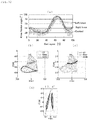
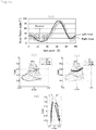
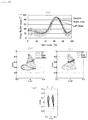
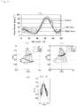
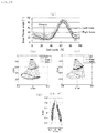
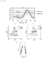
- Fig. 30(a) is a graph of knee flexion angle.
- the vertical axis indicates the knee flexion angle
- the horizontal axis indicates the gait cycle. Gait cycles 0% and 100% are the timing of the heel contact.
- the Tables describe, in the light-colored lines and region, the average values of the healthy persons measured by Measurer A 1st and its 95% confidence interval.
- the graphs are the average value of three gait cycles.
- Figs. 30(b) and (c) illustrate the sagittal plane trajectory of the three gait cycles and the acceleration vector of the second step out of the three steps at the time of the heel contact.
- Fig. 30(d) indicates the knee joint horizontal plane trajectories of the three gait cycles.
- a knee horizontal plane trajectory angle ⁇ xy is described in the upper part of the drawing. Subsequently, similar drawings are illustrated regarding each patient up to Fig. 39 .
- Fig. 30(a) the results of measurement of Patient A are taken as an example to describe the quantitative assessment of knee OA symptoms.
- Fig. 30(a) first, it can be seen that the peak value of the flexion angle of the left knee the severity of which is higher is significantly smaller than that of the healthy persons. This indicates restrictions on knee flexion due to knee pain. While the average value of the maximum knee flexion angles of the healthy persons is 84.9°, the left knee of Patient A is 72.4°. In addition, there is a large difference in step length between the right and the left due to knee pain in the left knee.
- the ratio of the right and left step lengths (right step length/left step length) of the healthy group is 1.02 ⁇ 0.08, almost the same between the right and the left, the right and left ratio of Patient A is 0.79.
- similarly due to knee pain in the left knee there is also a difference in stance ratio between the right and the left, and its value is also obtained as a measurement result.
- Tables 17 to 20 described below indicate results of comparisons between the gait parameters of the patient group and the healthy group.
- the Tables respectively indicate comparisons of the parameters of the right leg, the left leg, the side with higher severity, and the side with lower severity.
- Table 2 described above indicates which leg has higher severity.
- the average values of the right and left legs were used for both the side with higher severity and the side with lower severity.
- the p values in the Tables are values obtained when an unpaired t-test was conducted.
- the knee horizontal trajectory plane angle ⁇ xy a gait parameter calculated by the gait analysis system and the gait analysis method according to the present embodiment, exhibits a significant difference regarding both the right and left legs.
- the acceleration vector direction ⁇ acc exhibits a significant difference regarding the side with lower severity, enabling quantitative assessment of a disease, e.g., knee OA.
- the novel gait parameters are reviewed in detail below.
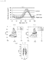
- the knee horizontal plane trajectory of Patient B whose knee horizontal plane trajectory angle is the largest is reviewed as an example.
- knee OA patients tend to have a reduced knee stability due to a reduction in articular cartilage.
- the instability becomes particularly a problem at the time of the heel contact at which a load applies and in the subsequent early stance phase, which is a load response phase.
- Fig. 31(d) it can be seen that the distance between the knee and the original point in the Y-direction is small at the time of the heel contact and in the early stance phase. This is presumably because the leg is brought closer to the original point, i.e., the gravity center position of the body, in order to make up for the instability of the knee.
- the load tends to decrease, and therefore the instability is less problematic.
- the distance between the original point and the swinging knee becomes small in preparation for the heel contact on the opposite side and the distance with respect to the standing knee is large.
- Even the knee horizontal plane trajectory angles of the knee OA patients without knee pain differ from that of the healthy group. Therefore, it is reasonable to presume that the knee instability is the cause.
- the smaller angle ⁇ acc of the knee acceleration vector direction of the knee OA patients as compared with the healthy persons is presumably due to an increase in rearward component and a reduction in vertical component of the acceleration vector.
- the causes of an increase in rearward component presumably include the generation of velocity in the forward direction immediately before the heel contact.
- knee OA patients tend to have a lower one-leg support ability than healthy persons. This is due to knee pain at the time of high loads or looseness of the knee.
- the reduction in vertical component is presumably due to a reduction in amount of displacement in the vertical direction due to a reduction in knee flexion angle.
- the knee flexion in the swing phase plays a role to ensure a clearance of the foot with respect to the ground.
- a reduction in knee flexion angle due to knee pain reduces the clearance.
- angle ⁇ acc in the knee acceleration vector direction was reduced due to knee OA symptoms including knee pain, knee instability, and knee flexion restrictions.
- Table 21 described below indicates results of a comparison of the acceleration of the ground coordinate system.
- the average values and the standard deviations of the rearward component a x , the vertical component a z , and their square-root of sum of squares a xz of the acceleration vector of the healthy group and the knee OA patient group are indicated.
- the p values in the Table are values at a time when an unpaired t-test was conducted. It can also be seen from the Table that the values a x and a xz are larger in the patient group and the value a z is smaller in the patient group.
- the present invention is not limited to the aforementioned embodiment, but a change may be properly made within the scope of the claims.
- the acceleration sensors and the angular velocity sensors are attached to both legs to acquire the gait parameters of both legs.
- the sensors may be attached to either one of the legs to calculate the gait parameters of only one leg.
Landscapes
- Health & Medical Sciences (AREA)
- Life Sciences & Earth Sciences (AREA)
- Physics & Mathematics (AREA)
- Heart & Thoracic Surgery (AREA)
- Molecular Biology (AREA)
- Dentistry (AREA)
- Biophysics (AREA)
- Pathology (AREA)
- Engineering & Computer Science (AREA)
- Biomedical Technology (AREA)
- Physiology (AREA)
- Medical Informatics (AREA)
- Oral & Maxillofacial Surgery (AREA)
- Surgery (AREA)
- Animal Behavior & Ethology (AREA)
- General Health & Medical Sciences (AREA)
- Public Health (AREA)
- Veterinary Medicine (AREA)
- Geometry (AREA)
- Measurement Of The Respiration, Hearing Ability, Form, And Blood Characteristics Of Living Organisms (AREA)
Abstract
Description
- The present invention relates to a gait analysis method and a gait analysis system using a body-worn sensor (also referred to as a "wearable sensor"), and particularly to a gait analysis method and a gait analysis system for calculating novel gait parameters useful for assessment of gait action.
- Measurement of gait action is used to assess gait abilities, to plan treatments, and to assess treatments in a quantitative manner. Conventionally, examples of general systems for gait measurement with an instrument include an optical three-dimensional motion analysis system. The measurement environment is subject to restrictions, generally requiring a long time for analysis. Therefore, the optical three-dimensional motion analysis system is only used in the area of research, and it is difficult to say that the optical three-dimensional motion analysis system has been in clinical use sufficiently.
- In recent years, development and research of a gait measurement system capable of easier measurement has drawn attention. In the past, gait measurement using an acceleration sensor attached to a human body was proposed by Morris (Non-Patent Literature 1). Since then, measurement methods using a small-sized sensor, e.g., an acceleration sensor or an angular velocity sensor, have been researched (Non-Patent
Literature 1 to 3). Thus, restrictions on measurement environments and a long required time, which were the problems with the conventional system, have been overcome, and it can be said that the practicability in clinical use has been increased. - However, most of the reports about sensor systems such as those described above indicate a mere acceleration comparison or two-dimensional gait measurement in which gait is recognized as a plane motion. A three-dimensional gait measurement system using a small-sized sensor has not been achieved.
- Given the above, the inventors of the present application have pursued the development of a three-dimensional gait analysis using an acceleration sensor and an angular velocity sensor (Non-Patent Literature 4 and 5). As a result, the inventors of the present application have succeeded to measure a three-dimensional motion considering rotation of a joint with high precision by means of an analysis method using quaternion calculation (Non-Patent Literature 6).
-
- Non-Patent Literature 1: Morris, J. R. W.; Accelerometry - a technique for the measurement of human body movements, Journal of Biomechanics 6, 729-736, (1973)
- Non-Patent Literature 2: Tao Liu, Yoshio Inoue, Kyoko Shibata: Development of a wearable sensor system for quantitative gait analysis, Measurement, Volume 42, )
- Non-Patent Literature 3: Pietro Picerno, Andrea Cereatti, Aurelio Cappozzo: Joint kinematics estimate using wearable inertial and magnetic sensing modulues, Gait & Posture 28, 588-595, (2008)
- Non-Patent Literature 4: Ryo Takeda, Shigeru Tadano, Masahiro Todoh, Manabu Morikawa, Minoru Nakayasu, Satoshi Yoshinari: Gait analysis using gravitational acceleration measured by wearable sensors, Journal of Biomechanics, Volume 42, )
- Non-Patent Literature 5: Ryo Takeda, Shigeru Tadano, Akiko Natorigawa, Masahiro Todoh, Satoshi Yoshinari: Gait posture estimation using wearable acceleration and gyro sensors, Journal of Biomechanics, Volume 42, )
- Non-Patent Literature 6: Hiroaki Miyagawa, Ryo Takeda, Shigeru Tadano: Kasokudo-Kakusokudo Sensa Ni Yoru Sanjigen Hoko Kaiseki (Three-dimensional gait analysis using acceleration and angular velocity sensors), Proceedings of the Japan Society of Mechanical Engineers annular meeting of 2010, Vol. 5: 63-64, 2010
- It is an object of the present invention to develop the conventional three-dimensional gait analysis using an acceleration sensor and an angular velocity sensor to provide a gait analysis method and a gait analysis system that can obtain novel gait parameters useful for assessment of gait actions of a subject.
- The present invention solves the aforementioned problem, and a gait analysis method of the present invention is characterized in that a tri-axial acceleration sensor and a tri-axial angular velocity sensor are attached to lower limb portions across at least one joint of joints constituting at least one of lower limbs of a subject, acceleration and angular velocity of each lower limb portion are respectively measured with the tri-axial acceleration sensor and the tri-axial angular velocity sensor during gait of the subject, the posture of each lower limb portion during the gait is calculated on the basis of the acceleration and the angular velocity measured, the lower limb portions in the calculated posture are coupled to one another to construct a three-dimensional model including a motion trajectory of the at least one joint, and an angle of an acceleration vector of the at least one joint at the time of heel contact with regard to the motion trajectory in a sagittal plane is calculated as a gait parameter.
- A gait analysis system of the present invention is characterized by including a tri-axial acceleration sensor and a tri-axial angular velocity sensor attached to lower limb portions across at least one joint of joints constituting at least one of lower limbs of a subject to respectively measure acceleration and angular velocity of each lower limb portion during gait of the subject, a model construction means for calculating the posture of each lower limb portion during the gait on the basis of the acceleration and the angular velocity measured and constructing a three-dimensional model including a motion trajectory of the at least one joint by coupling the lower limb portions in the calculated posture to one another, and a gait parameter calculation means for calculating an angle of an acceleration vector of the at least one joint at the time of heel contact with regard to the motion trajectory in a sagittal plane as a gait parameter.
- With the gait analysis method and the gait analysis system according to the present invention, a three-dimensional model including a motion trajectory of at least one joint is constructed on the basis of acceleration data and angular velocity data of each lower limb portion during gait of a subject, and an angle formed by the motion trajectory and an acceleration vector of a joint at the time of heel contact is calculated, enabling determination of novel gait parameters useful for gait analysis.
- In the gait analysis method of the present invention, the at least one joint may be a knee joint.
- In addition, in the gait analysis method of the present invention, the three-dimensional model including the motion trajectory of at least one joint may be constructed with respect to each of right and left lower limbs of the subject.
- Furthermore, in the gait analysis method of the present invention, approximation straight lines may be formed with respect to the motion trajectories of right and left joints in a horizontal plane, and an angle formed between the approximation straight lines may be calculated as a gait parameter.
- Furthermore, in the gait analysis method of the present invention, a Lissajous figure of a joint may be created from a three-dimensional model, and a gait parameter may be calculated on the basis of the Lissajous figure.
- In addition, the gait analysis system of the present invention may be configured such that the tri-axial acceleration sensor and the tri-axial acceleration sensor are attached to the right and left lower limbs of a subject, the gait parameter calculation means forms approximation straight lines with respect to the motion trajectories of the right and left joints in a horizontal plane, and calculates an angle formed between the approximation straight lines as a gait parameter.
- Furthermore, the gait analysis system of the present invention may be configured such that the parameter calculation means creates a Lissajous figure of a joint from a three-dimensional model and calculates a gait parameter on the basis of the Lissajous figure.
-
-
Fig. 1 is a view describing fundamental planes of a body motion. -
Fig. 2 is a view illustrating a direction of flexion and extension motions and a range of motion of a hip joint. -
Fig. 3 is a view illustrating a direction of adduction and abduction motions and a range of motion of a hip joint. -
Fig. 4 is a view illustrating a direction of internal rotation and external rotation motions and a range of motion of a hip joint. -
Fig. 5 is a view illustrating a direction of flexion and extension motions and a range of motion of a knee joint. -
Fig. 6 is a view illustrating a direction of plantar flexion and dorsi flexion and a range of motion of an ankle joint. -
Fig. 7 is a view illustrating a direction of adduction and abduction and a range of motion of an ankle joint. -
Figs. 8(a) and (b) are views describing a method of expressing an orientation of an ordinate system of a three-dimensional space. -
Fig. 9 is a view illustrating two coordinate systems in a three-dimensional space. -
Fig. 10 is a view describing general Euler angles. -
Fig. 11 is a block configurational diagram of a processing device of a gait analysis system according to an embodiment of the present invention. -
Fig. 12 is views illustrating a sensor attachment arrangement of a gait analysis system according to the aforementioned embodiment and a gait analysis method according to an embodiment of the present invention using the same,Fig. 12(a) is a front view, andFig. 12(b) is a rear view. -
Fig. 13 is a view describing a wire-frame model of lower limbs according to the aforementioned embodiment. -
Fig. 14 is views describing a sensor coordinate system, a ground coordinate system, and a segment coordinate system according to the aforementioned embodiment,Fig. 14(a) is a side view, andFig. 14(b) is a front view. -
Fig. 15 illustrates a definition of a coordinate system of a right thigh segment according to the aforementioned embodiment,Fig. 15(a) is a side view, andFig. 15(b) is a front view. -
Fig. 16 illustrates a definition of a coordinate system of a right shank segment according to the aforementioned embodiment,Fig. 16(a) is a side view, andFig. 16(b) is a front view. -
Fig. 17 is a diagram illustrating an analysis flow according to the gait analysis system and the gait analysis method according to the aforementioned embodiment. -
Fig. 18 is a view describing a principle of calculating an initial posture (initial orientation) of a sensor from acceleration data. -
Fig. 19 is a view illustrating a seated posture for measurement of acceleration data at rest. -
Fig. 20 is views illustrating two gravitational acceleration vectors for use in defining a sensor coordinate system. -
Fig. 21 is graphs illustrating states before and after low-pass filter processing with respect to data obtained from an angular velocity sensor, the upper illustrates a state before the processing, and the lower illustrates a state after the processing. -
Fig. 22 is a graph illustrating a gyro bias included in data obtained from an angular velocity sensor. -
Fig. 23 is a graph illustrating a change of an angular velocity of a shank during gait. -
Fig. 24 is a graph illustrating a distance in a walking direction from an original point (midpoint of right and left hip joint centers) to a right toe. -
Fig. 25 is a view illustrating motion trajectories of joints in a sagittal plane and an acceleration vector at the time of heel contact. -
Fig. 26 is a view illustrating motion trajectories of knee joints in a horizontal plane and a trajectory angle of knee joints in a horizontal plane. -
Fig. 27 is a flowchart indicating a data flow of a gait analysis system according to the aforementioned embodiment. -
Fig. 28 is a flowchart indicating a procedure of an experiment according to the gait analysis system and the gait analysis method according to the aforementioned embodiment. -
Fig. 29 is photographs illustrating a walkway employed in the aforementioned experiment,Fig. 29(a) is a straight flat way of 7 m, andFig. 29(b) is a treadmill. -
Fig. 30 is graphs illustrating results of measurement of gait of Patient A,Fig. 30(a) is a graph illustrating a knee flexion angle,Fig. 30(b) is a graph illustrating motion trajectories of joints (great trochanter, knee joint, ankle joint) of a right leg in a sagittal plane,Fig. 30(c) is a graph illustrating motion trajectories of joints (great trochanter, knee joint, ankle joint) of a left leg in a sagittal plane, andFig. 30(d) is a graph illustrating motion trajectories of knee joints in a horizontal plane. -
Fig. 31 is graphs illustrating results of measurement of a gait of Patient B,Fig. 31(a) is a graph illustrating a knee flexion angle,Fig. 31(b) is a graph illustrating motion trajectories of joints (great trochanter, knee joint, ankle joint) of a right leg in a sagittal plane,Fig. 31(c) is a graph illustrating motion trajectories of joints (great trochanter, knee joint, ankle joint) of a left leg in a sagittal plane, andFig. 31(d) is a graph illustrating motion trajectories of knee joints in a horizontal plane. -
Fig. 32 is graphs illustrating results of measurement of gait of Patient C,Fig. 32(a) is a graph illustrating a knee flexion angle,Fig. 32(b) is a graph illustrating motion trajectories of joints (great trochanter, knee joint, ankle joint) of a right leg in a sagittal plane,Fig. 32(c) is a graph illustrating motion trajectories of joints (great trochanter, knee joint, ankle joint) of a left leg in a sagittal plane, andFig. 32(d) is a graph illustrating motion trajectories of knee joints in a horizontal plane. -
Fig. 33 is graphs illustrating results of measurement of gait of Patient D,Fig. 33(a) is a graph illustrating a knee flexion angle,Fig. 33(b) is a graph illustrating motion trajectories of joints (great trochanter, knee joint, ankle joint) of a right leg in a sagittal plane,Fig. 33(c) is a graph illustrating motion trajectories of joints (great trochanter, knee joint, ankle joint) of a left leg in a sagittal plane, andFig. 33(d) is a graph illustrating motion trajectories of knee joints in a horizontal plane. -
Fig. 34 is graphs illustrating results of measurement of gait of Patient E,Fig. 34(a) is a graph illustrating a knee flexion angle,Fig. 34(b) is a graph illustrating motion trajectories of joints (great trochanter, knee joint, ankle joint) of a right leg in a sagittal plane,Fig. 34(c) is a graph illustrating motion trajectories of joints (great trochanter, knee joint, ankle joint) of a left leg in a sagittal plane, andFig. 34(d) is a graph illustrating motion trajectories of knee joints in a horizontal plane. -
Fig. 35 is graphs illustrating results of measurement of gait of Patient F,Fig. 35(a) is a graph illustrating a knee flexion angle,Fig. 35(b) is a graph illustrating motion trajectories of joints (great trochanter, knee joint, ankle joint) of a right leg in a sagittal plane,Fig. 35(c) is a graph illustrating motion trajectories of joints (great trochanter, knee joint, ankle joint) of a left leg in a sagittal plane, andFig. 35(d) is a graph illustrating motion trajectories of knee joints in a horizontal plane. -
Fig. 36 is graphs illustrating results of measurement of gait of Patient G,Fig. 36(a) is a graph illustrating a knee flexion angle,Fig. 36(b) is a graph illustrating motion trajectories of joints (great trochanter, knee joint, ankle joint) of a right leg in a sagittal plane,Fig. 36(c) is a graph illustrating motion trajectories of joints (great trochanter, knee joint, ankle joint) of a left leg in a sagittal plane, andFig. 36(d) is a graph illustrating motion trajectories of knee joints in a horizontal plane. -
Fig. 37 is graphs illustrating results of measurement of gait of Patient H,Fig. 37(a) is a graph illustrating a knee flexion angle,Fig. 37(b) is a graph illustrating motion trajectories of joints (great trochanter, knee joint, ankle joint) of a right leg in a sagittal plane,Fig. 37(c) is a graph illustrating motion trajectories of joints (great trochanter, knee joint, ankle joint) of a left leg in a sagittal plane, andFig. 37(d) is a graph illustrating motion trajectories of knee joints in a horizontal plane. -
Fig. 38 is graphs illustrating results of measurement of gait of Patient I,Fig. 38(a) is a graph illustrating a knee flexion angle,Fig. 38(b) is a graph illustrating motion trajectories of joints (great trochanter, knee joint, ankle joint) of a right leg in a sagittal plane,Fig. 38(c) is a graph illustrating motion trajectories of joints (great trochanter, knee joint, ankle joint) of a left leg in a sagittal plane, andFig. 38(d) is a graph illustrating motion trajectories of knee joints in a horizontal plane. -
Fig. 39 is graphs illustrating results of measurement of gait of Patient J,Fig. 39(a) is a graph illustrating a knee flexion angle,Fig. 39(b) is a graph illustrating motion trajectories of joints (great trochanter, knee joint, ankle joint) of a right leg in a sagittal plane,Fig. 39(c) is a graph illustrating motion trajectories of joints (great trochanter, knee joint, ankle joint) of a left leg in a sagittal plane, andFig. 39(d) is a graph illustrating motion trajectories of knee joints in a horizontal plane. -
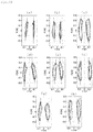
Figs. 40(a) to (h) are graphs illustrating motion trajectories of knee joints of healthy persons in a horizontal plane. -
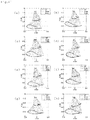
Figs. 41(a) to (h) are graphs illustrating motion trajectories of joints of right legs of healthy persons in a sagittal plane and acceleration vectors at the time of heel contact. - First, terms and technical terms regarding gait used herein are described.
- As illustrated in
Fig. 1 , there are three fundamental planes of a body motion as described below. - Horizontal plane
A plane dividing a body into upper and lower parts; also called a transverse plane. - Coronal plane
A plane dividing a body into front and rear parts. - Sagittal plane
A plane dividing a body into right and left parts. - When a body motion is rotation, the body motion can be expressed with reference to an axis, not a plane. This is defined as follows:
- Median axis: A line segment common to a coronal plane and a sagittal plane.
- Frontal-horizontal axis: a line segment common to a coronal plane and a horizontal plane.
- Sagittal-horizontal axis: a line segment common to a sagittal plane and a horizontal plane.
- A motion of a lower limb joint and an average range of motion of a joint of a healthy person are described.
- A hip joint is a three-degree-of-freedom joint that enables flexion and extension motions, adduction and abduction motions, and internal rotation and external rotation motions.
-
Fig. 2 illustrates a direction of flexion and extension motions and a range of motion of a hip joint. A direction in which a leg is swung forward is the flexion direction. -
Fig. 3 illustrates a direction of adduction and abduction motions and a range of motion of a hip joint. It is a rotation in the coronal plane in which a direction in which a foot approaches the median axis is the adduction and a direction in which a foot moves away from the median axis is the abduction. -
Fig. 4 illustrates a direction of internal rotation and external rotation motions and a range of motion of a hip joint. It is a rotation about an axis of a thigh. When a point is marked on a front surface of the thigh, a direction in which the point approaches the fundamental sagittal plane is the internal rotation and a direction in which the point moves away from the fundamental sagittal plane is the external rotation. -
Fig. 5 illustrates a direction of flexion and extension and a range of motion. A direction in which a foot approaches buttocks is the flexion direction and a direction in which a foot moves away from buttocks is the extension direction. In the field of motion analysis, a knee joint is often considered a hinge joint. However, technically, the motion of a knee joint is not limited to flexion and extension, but the movable motion can be expanded in the adduction and abduction directions or in the internal rotation and external rotation directions due to impairment, e.g., damage to an anterior cruciate ligament. In the field of orthopedic surgery, the motion of a knee joint is generally treated three-dimensionally. Therefore, according to the present invention, a knee joint is treated as a spheroidal joint. A direction in which a knee joint has varus deformity (bowleg) is the adduction direction, and a direction in which a knee joint has valgus deformity (knock knee) is the abduction direction. A direction in which the front surface of a shank faces inward relative to the thigh is the internal rotation direction, and a direction in which the front surface of a shank faces outward is the external rotation direction. - An ankle joint performs dorsi flexion and plantar flexion motions, and adduction and abduction motions.
Fig. 6 illustrates a direction of plantar flexion and dorsi flexion, and a range of motion. A direction in which a toe is pressed down toward the sole is the plantar flexion direction, and an opposite direction is the dorsi flexion direction.Fig. 7 illustrates a direction of adduction and abduction and a range of motion. A direction in which a toe approaches the median axis is the adduction, and a direction in which a toe moves away from the median axis is the abduction. - In the case of general gait, the heel contacts the ground first, and the toe leaves the ground last. In particular, an action in which a heel contacts the ground during gait is called heel contact or heel strike, and an action in which a toe leaves the ground is called toe off. A time required from the heel contact to the next heel contact of the same foot is called a gait cycle. The gait cycle is divided into a stance phase and a swing phase. The stance phase indicates a phase from the heel contact to the toe off, i.e., a state in which the foot is on the ground. The swing phase is a phase from the toe off to the heel contact, i.e., a state in which the foot is off the ground. In the case of healthy gait, the stance phase and the swing phase of the gait cycle account for about 60% and about 40%, respectively.
- Herein, methods of expressing an "orientation (posture)" of a coordinate system in a three-dimensional space are described. Expressions of directions in a three-dimensional space include "direction" and "orientation". They differ, in short, in that the direction is the direction of a vector and the orientation is the posture of a coordinate system. For example, as illustrated in
Fig. 8(a) , a direction having a vector is illustrated. A rotation about the axis of the vector does not provide any apparent change. As illustrated inFig. 8(b) , an orientation having a coordinate system is illustrated. Even when a rotation is made about one basic axis therefrom, the rotation can be observed according to a change of the direction of another basic axis. When the relationship between the orientations of two coordinate systems can be expressed by conversion by means of a unit matrix E, the relationship between the two coordinate systems is said to be in an "identical state". In the identical state, the corresponding basic axes of the two coordinate systems are parallel to each other. An angular displacement from the identical state is called the orientation. The angular displacement indicates a quantity varying with rotation. - In a three-dimensional coordinate system, a general method of expressing the orientation in the field of mathematics is a matrix. A coordinate system O-XYZ and a coordinate system O'-xyz illustrated in
Fig. 9 are considered in a three-dimensional space. The coordinate system O'-xyz can freely move in the coordinate system O-XYZ. At this time, the orientation of the coordinate system O'-xyz, which is observed from the coordinate system O-XYZ, is determined. - The coordinate system O'-xyz starts in the identical state with respect to the coordinate system O-XYZ, and predetermined rotation operation is performed. The orientation of the coordinate system O'-xyz as of the present time is illustrated. Now, when basic vectors ex, ey, ez of O'-xyz are known to be vectors of the coordinate system O-XYZ, a rotation matrix indicated in Equation (1) is determined from these three vectors.
- [Equation 1]

- By making use of the fact that Equation (1) is an orthogonal matrix, inverse conversion is determined by transposition of it.
- [Equation 2]

- As a general method of expressing the motion of a body, there is a concept called Euler angles. In the field of orthopedic surgery or biomechanics, the Euler angles are used with respect to the motion of a three-degree-of-freedom joint, e.g., a shoulder joint or a hip joint. The Euler angles are less used for those modeled as a joint with only flexion and extension motions, e.g., a knee joint.
- The Euler angles are named after Leonhard Euler, who proved that any orientation can be expressed by rotation of three different axes. There are many definitions of the Euler angles depending on the combination of an order of rotation. Three parameters expressing the amount of rotation depend on an order of rotation. For correct expression of the orientation, it is necessary to describe the definitions of the Euler angles to be used. The z-y-x Euler angles, general Euler angles, are introduced in conjunction with
Fig. 10 . First, a coordinate system in the identical state with the coordinate system O-xyz described in (6) above is considered. First, rotation at an angle ϕ about the z axis is performed. This is called a "heading angle". Next, rotation at an angle θ about the y axis after the rotation is performed. This is called a "pitch angle". Finally, rotation at an angle ϕ about the x axis after the above rotation is performed. This is called a "bank angle". Equation (3) indicates a rotation matrix of the z-y-x Euler angles. - [Equation 3]

- In Equation (3), symbols sin and cos are abbreviated as s and c, respectively. Symbols Rx, Ry and Rz are as described in Equations (4) to (6).
- [Equation 4]

- [Equation 5]

- [Equation 6]

- The rotations of the Euler angles in the case of inverse conversion, i.e., when rotation is performed in an order of x-y-z axes, are called a roll angle, a pitch angle, and a yaw angle, respectively. These are called Cardan angles, which are most frequently used in biomechanics.
- The number of parameters minimally required for expression of a three-dimensional angular displacement is three. The Euler angles are expressed by minimally required three angles. In addition, such parameters are directly linked to angle data and are therefore very intuitive. However, the Euler angles are merely a forward kinematical "orientation expressing method", but are not a calculation method. Calculation is somewhat troublesome when an orientation indicated by certain Euler angles is changed to an orientation indicated by different Euler angles. In addition, there is also a problem called gimbal lock. Also from a viewpoint of algorithm construction, the Euler angles are not a preferable method because of conditional processing with regard to singularities and an increase in number of times of calculation as indicated by Equation (3).
- The quaternion is a type of "hypercomplex numbers", which is an extension of complex numbers. In recent years, the quaternion is applied to the field of 3D computer graphics and spacecraft attitude control.
- The quaternion is formed of one scalar element and one vector element. As methods of expressing a quaternion, there are various methods including a method of expressing a quaternion as a matrix and a method of expressing a quaternion using an exponential map. Herein, the expression described below is used.
- [Equation 7]

- Symbols W, X, Y and Z are quaternion parameters. Similar to V, symbols X, Y and Z can be expressed as vectors. When quaternions are used in an orientation expressing method, the quaternions are easier to understand as they are expressed as vectors. Symbols i, j and k are called quaternion units that are similar in property to imaginary numbers.
- [Equation 8]

- The quaternion has a norm, which is defined in Equation (9) .
- [Equation 9]

- The quaternion having ∥Q∥ = 1 is particularly called a unit quaternion, which is indicated by Equation (10).
- [Equation 10]

- The quaternion is a type of hypercomplex numbers. Therefore, similar to complex numbers, there is a concept called a conjugate quaternion, which is indicated by Equation (11).
- [Equation 11]

- In the case of q = (w1;v1) and q2 = (w2;v2), a product of the unit quaternions is indicated by Equation (12).
- [Equation 12]

- A geometric significance of the quaternion is described. The unit quaternion indicating rotation can be indicated by Equation (13) using cos and sin.
- [Equation 13]

- Here, symbol n is a unit vector. Now, a vector r in a three-dimensional space is considered. This vector is indicated as r = (0; rx, ry, rz) in quaternion notation. A real component may be any value and here is zero for the sake of simplicity.
- The rotation in a three-dimensional space can be expressed in conjunction with the description given heretofore. When r defined above is rotated to be r', this phenomenon can be expressed by Equation (14).
- [Equation 14]

- In this case, the unit quaternions n and θ used for rotation indicated in Equation (13) indicate a vector indicating an axis of rotation and the amount of rotation about the axis, respectively.
- According to the present invention, as will be described below, the quaternions are used for computation of angular displacement.
- In view of the above, an embodiment of the present invention is described in detail on the basis of the drawings. A gait analysis system and a gait analysis method according to the embodiment measure acceleration and angular velocity of a body part during gait of a subject, estimates a lower limb posture on the basis of the measurement data, and calculates a gait parameter required for assessment of gait.
- As illustrated in
Fig. 11 , agait analysis system 1 includessensor units 3 for measuring acceleration and angular velocity of a body part during gait, aprocessing device 5 for acquiring acceleration data and angular velocity data from thesensor units 3 and executing processing of calculating a parameter for gait assessment, and amonitor screen 7 for displaying results of gait assessment. - Each
sensor unit 3 is formed as one tri-axial acceleration sensor, one bi-axial angular velocity sensor, and one uni-axial angular velocity sensor are configured as a unit. Thesensor unit 3 detects acceleration of perpendicular three axial directions and angular velocity about the axes. The acceleration sensor and the angular velocity sensor may not be configured as a unit. As thesensor unit 3, for example, WAA-006 manufactured by Wireless Technologies, Inc. may be used. In the present embodiment, sevensensor units 3 are used. The attachment locations and the method will be described later. - Each
sensor unit 3 is configured to transmit acceleration data and angular velocity data detected by the acceleration sensor and the angular velocity sensor, respectively, to theprocessing device 5 in real time via wireless communication. Eachsensor unit 3 includes a software timer. At the timing of measurement of acceleration and angular velocity with the internal sensors, a timer value is stored together. Thus, all the sensor units are synchronized. A sampling frequency is set to 100 Hz. -
Figs. 12(a) and (b) illustrate attachment positions and an attachment method for thesensor units 3 with respect to a subject (testee) at the time of data measurement. A total of sevensensor units 3 are attached to the pelvis, the right and left thighs, the right and left shanks, and the right and left feet, respectively. Thesensor units 3 may be fixed in a predetermined position by being housed in pockets formed on sports tights or pockets formed on a sports band worn by a subject during gait. Thesensor units 3 are not subjected to any particular limitation regarding fixing position, but may be arranged at any location on the aforementioned portions. However, in order to minimize the angular velocity that can be generated on the sensors by the muscle activity, it is preferable that thesensor unit 3 on the pelvis be fixed to the midpoint of the right and left posterior iliac crests, thesensor units 3 on the thighs be fixed to the quadriceps muscle middle portions, and thesensor units 3 on the shanks be attached to the inner sides of the front parts of the tibiae. Thesensor units 3 on the feed can be fixed to the surfaces of shoes by means of a sports band or the like. However, it is preferable to avoid the vicinity of the metatarsal joint and to select proper locations to be free of influences by plantar and dorsi flexion. The directions of thesensor units 3 when fixed may be arbitrary because the directions are corrected by a method that will be described later. Incidentally,reference numeral 4 in the drawings indicates markers that will be described later. - Next, modeling of lower limbs is described. In the present embodiment, a three-dimensional wire-frame model such as that illustrated in
Fig. 13 is constructed to express the posture of a body part during gait. This is an extension of a method of expressing a part of a body as a rigid body link model, and a plane is formed of wires. This enables expression of not only the directions, but also the posture (orientation) of a body part. Parts expressed by wires are regarded as rigid bodies, which are called segments for the sake of convenience. Each of the segments is capable of independent motion. The lower limb model is formed of a total of seven segments: a pelvis segment, right and left thigh segments, right and left shank segments, and right and left foot segments. The details are described below. - The pelvis segment is formed of six points: right and left anterior superior iliac spines, right and left posterior iliac crests, and right and left hip joint centers.
- The thigh segment is formed of four points: a hip joint center, a great trochanter, a medial knee joint space, and a lateral knee joint space.
- The shank segment is formed of a lateral condyle of tibia, a medial knee joint space, a lateral knee joint space, and an ankle joint center. The ankle joint center is a midpoint of the lateral malleolus and the medial malleolus.
- The ankle joint segment is formed of three points: an ankle joint center, a heel bone, and a toe.
- The construction of a wire-frame model requires body dimensions. The body dimensions measured at the time of gait measurement are described below. In this system, the body dimensions may be input with an input means, e.g., a keyboard connected to the processing device.
- Intertrochanteric distance: A straight-line distance between right and left great trochanters
- Thigh length: A distance from a great trochanter to a lateral epicondyle of femur
- Shank length: A distance from a lateral condyle of tibia to an ankle joint lateral malleolus
- The pelvis segment is modeled such that the pelvis segment has an average shape consistently and the size varies in proportion to the intertrochanteric distance.
- In the present embodiment, for calculation and expression of gait postures, three types of coordinate systems: a sensor coordinate system, a ground coordinate system, and a segment coordinate system are used. A right thigh is taken as an example, and three coordinate systems are illustrated in
Figs. 14(a) and (b) . In these drawings only, the sensor coordinate system is indicated by reference symbol Csn, the ground coordinate system is indicated by reference symbol Ce, and the segment coordinate system is indicated by reference symbol Csg. - The ground coordinate system is a stationary system for observation of motion, and is defined such that the z-axis is taken vertically upward and the x-axis is taken parallel to the initial sagittal-horizontal axis of a subject and anteriorly from the subject. The y-axis is taken to be perpendicular to both of them to form a right-handed system.
-
Figs. 15(a) and (b) illustrate the definition of the coordinate system of the thigh segment. The z-axis is taken parallel to a line connecting the great trochanter and the lateral knee joint space, and the sagittal-horizontal axis (front direction, walking direction) is taken as the x-axis. -
Figs. 16(a) and (b) illustrate the definition of the coordinate system of the shank segment. The z-axis is taken parallel to a line connecting the knee joint center and the ankle joint center, and the sagittal-horizontal axis (front direction, walking direction) is taken as the x-axis. The knee joint center is a midpoint of the lateral knee joint space and the medial knee joint space, and the ankle joint center is a midpoint of the ankle joint lateral malleolus and the ankle joint medial malleolus. - The coordinate systems of the pelvis segment and the foot segments are defined to correspond to the ground coordinate system in a standing posture. When the standing posture is assumed, the toes are directed forward and the feet are aligned.
- Next, returning to
Fig. 11 , theprocessing device 5 of the gait analysis system is described. Additionally, a processing flow with the system is illustrated inFig. 17 . In the present embodiment, theprocessing device 5 uses a personal computer, but may be anything insofar as it can acquire acceleration data and angular velocity data from thesensor units 3 and perform predetermined computation processing to indicate a predetermined gait parameter on themonitor screen 7 or output or record a predetermined gait parameter on a different device. - As illustrated in
Fig. 11 , theprocessing device 5 includes adata acquisition portion 11 for acquiring acceleration data and angular velocity data from eachsensor unit 3, a sensorposture estimation portion 13 for estimating the posture (orientation) of the sensor coordinate system on the basis of the acceleration data and the angular velocity data of each body part, the acceleration data and the angular velocity data being acquired by thedata acquisition portion 11, a segmentposture computation portion 15 for computing the posture of each segment by converting the posture estimated by the sensorposture estimation portion 13 into the posture (orientation) of the segment coordinate system, a lower limbposture computation portion 17 for creating each segment on the basis of the posture of each segment computed by the segmentposture computation portion 15 and body dimensions input and coupling the created segments in a predetermined posture so as to compute a lower limb posture (three-dimensional wire-frame model) during gait, and a gaitparameter computation portion 19 for calculating a gait parameter on the basis of the lower limb posture computed by the lower limbposture computation portion 17. Thedata acquisition portion 11, the sensorposture estimation portion 13, the segmentposture computation portion 15, and the lower limbposture computation portion 17 described above constitute the model construction means of the present invention. In addition, the aforementioned gaitparameter computation portion 19 constitutes the gait parameter calculation means of the present invention. - The sensor
posture estimation portion 13 estimates the posture of the sensor during gait in the manner described below. - First, in the case of plane rotation, an angular displacement θ can be calculated by Equation (15).
- [Equation 15]

- In Equation (15), the first term of the right-hand side indicates an initial posture (orientation), and the second term indicates an angular displacement from the initial posture. In the present embodiment, the initial posture is estimated through the use of the acceleration data obtained by the acceleration sensor. Furthermore, the angular displacement is estimated through the use of the angular velocity data obtained from the angular velocity sensor.
- The principle of determining the initial posture of the sensor from the acceleration data is described with reference to
Fig. 18 . The acceleration sensor detects a motion acceleration a and a gravitational acceleration g simultaneously. - [Equation 16]

- In particular, for example, at rest or in constant velocity motion, when motion acceleration does not apply with respect to the acceleration sensor, the acceleration sensor detects a gravitational acceleration component only.
- [Equation 17]

- Accordingly, an angle formed by the vertical axis (gravity direction) and the detection axes of the acceleration sensor can be calculated from the proportion of the detection axes of the acceleration sensor and the vector sum.
- [Equation 18]

- In the case of three dimensions, in principle, even when rotation occurs about the gravity axis, it is impossible for the acceleration sensor to detect the acceleration, and only the initial posture is detected by the acceleration sensor. Therefore, the heading angle of the aforementioned Euler angles at a time when a subject assumes the initial posture may be defined to be 0°.
- Next, the angular displacement is determined. Parameters input to unit quaternions indicating rotation include the axis of rotation and the amount of rotation about the axis. The quaternion is used to calculate the angular displacement because it is easy to match up with the angular velocity data obtained by the angular velocity sensor. An axis of rotation n and an amount of rotation θ are indicated by Equations (19) and (20) described below, respectively.
- [Equation 19]

- [Equation 20]

- Symbol ω indicates an angular velocity vector obtained from the detected acceleration of each axis of the angular sensor, and symbol Δts indicates a sampling period. They are substituted into the aforementioned Equation (13), and the result is described below.
- [Equation 21]

- As a result of the input, a micro angular displacement per sampling period in which the angular velocity vector is the axis of rotation is obtained. Then, as this is integrated in time domain, the angular displacement from the initial posture is determined. In this way, the sensor
posture estimation portion 13 estimates the posture of thesensor units 3. - Next, conversion of coordinate systems by the segment
posture computation portion 15 is described. According to the present invention, thesensor units 3 are attached to body parts corresponding to the respective segments and measurement is performed to determine the posture of each body part (segment). However, it is difficult or impossible to attach thesensor units 3 such that the sensor coordinate system corresponds to the segment coordinate system. Therefore, for estimation of the motion of the segments, it is necessary that an experiment different from the gait experiment be performed to determine the relative postures between the sensor coordinate system and the segment coordinate system, and the posture of the sensor coordinate system be converted into the posture of the segment coordinate system. - Under conditions that factors including muscle contraction, clothing, and skin displacement are negligible, the
sensor unit 3 and the segment exhibit a similar angular motion. Therefore, when the posture of thesensor unit 3 is determined, the posture of the segment can be determined as a result of rotation operation. - In reality, the following two processes are taken to determine the rotation matrix from the sensor coordinate system to the segment coordinate system.
- Rotation matrix from the sensor coordinate system to the ground coordinate system
- Rotation matrix from the ground coordinate system to the segment coordinate system
- The manner of determining the rotation matrix from the sensor coordinate system to the ground coordinate system is described. The acceleration data is measured when a subject is at rest in a standing posture or at rest in a seated posture. The standing posture is a state that a subject upstands on a horizontal ground where both toes are aligned as illustrated in
Fig. 16 . The seated posture is as illustrated inFig. 19 . The toes are also aligned in the seated posture. Thus, the gravitational accelerations in the case of the two postures: the standing posture and the seated posture can be obtained. - The manner of determining the rotation matrix from the sensor coordinate system to the ground coordinate system on the basis of the above is described in conjunction with
Fig. 20 . An arrow g positioned at the middle indicates the gravitational acceleration in the standing position, and an arrow g positioned on the right side indicates the gravitational acceleration in the seated position. The z-axis of the ground coordinate system is defined to be the direction opposite to that of the gravitational acceleration in the standing position. The y-axis is defined by a cross product of the gravitational acceleration in the standing position and the gravitational acceleration in the seated position. The x-axis is defined by a cross product of the y-axis and the z-axis. - Thus, the basic vector of the ground coordinate system with respect to the sensor coordinate system can be acquired.
- The rotation from the ground coordinate system to the segment coordinate system provides the segment coordinate system with respect to the ground coordinate system from a front view photograph and a side view photograph in the standing posture as illustrated in
Fig. 14 , and the rotation matrix from the ground coordinate system to the segment coordinate system can be obtained. - In addition, the system of the present embodiment includes a filtering means. The data obtained by the angular velocity sensor includes noise. Because the noise is high frequency, the noise can be removed by a low-pass filter. As the low-pass filter, for example, a Butterworth filter of an IIR digital filter may be used. In this case, the cutoff frequency can be 12 Hz. However, the use of this filter results in generation of a phase delay, but the filtering processing with the same property is performed twice in total: one before the data and the other after the data to eliminate the phase delay.
Fig. 21 illustrates results of the low-pass filter processing by comparing the states before and after the filtering processing. - In addition, the data obtained from the angular velocity sensor contain bias. This is described in conjunction with an angular velocity waveform at the time of gait measurement illustrated in
Fig. 22 . The horizontal axis indicates the time elapsed from beginning of measurement, and the vertical axis indicates the angular velocity about the y-axis of the sensor arranged on the right thigh. The angular velocity sensor records a non-zero value as a detected value even at rest. This is a bias of the angular velocity. As described above, in the present embodiment, the method of calculating the angular displacement includes an integration element. Therefore, biases are accumulated during numerical integration, which directly leads to errors. Thus, it is necessary that the amount of bias be estimated and be subtracted from the original data before integration calculation. There are various bias estimation methods. Here, for bias estimation, the mode of raw data is estimated to be bias. - The gait
parameter computation portion 19 calculates various types of parameters required for gait assessment from the lower limb posture computed by the lower limb posture computation portion with a predetermined program and the timings of the heel contact and the toe off. The timings of the heel contact and the toe off can easily be determined by means of an optical system or a floor reaction force gauge. However, in the present embodiment, only the acceleration and angular velocity data are used for detection. Specifically, as described below, the timing of the heel contact is detected from the angular velocity data of the shank, and the timing of the toe off is detected from the relative positions of the right and left toes. - As illustrated in
Fig. 23 , the angular velocity of the shank during gait is close to 0 degrees/second in the stance phase, and a relatively large angular velocity is generated in the swing phase because the shank is swung forward. Immediately before the heel contact, the shank swung forward is slightly pulled backward. Therefore, the peak value of the angular velocity appears in the direction opposite to that of the swing phase. This peak position is used for detection of the heel contact. -
Fig. 24 illustrates a distance in walking direction from the original point (midpoint of the right and left hip joint centers) to the right toe. This is a graph indicating a standing state at rest at the onset and the beginning of gait at the point near 1.5 seconds. When the gait begins, first, the right leg is swung forward, and the distance from the original point increases in a positive direction. The heel contact is made slightly after the positive peak position. Upon entry into the stance phase, the distance from the original point decreases, and subsequently the toe is shifted backward beyond the original point. Therefore, the distance from the original point increases in a negative direction. Then, the toe off is made, and the right leg again begins to swing forward, and the distance from the original point starts increasing in the positive direction. Until the toe off is made, the distance from the original point monotonically increases in the negative direction. Therefore, the negative peak position presumably corresponds to the timing of the toe off. In the present embodiment, the relative position of the toe is calculated from the lower limb posture obtained by the lower limbposture computation portion 17, and the timing at which the relative distance from the original point assumes the negative peak position is the timing of the toe off. - Next, gait parameters calculated by the gait
parameter computation portion 19 from the lower limb posture computed by the lower limbposture computation portion 17 and the timings of the heel contact and the toe off are described below. These gait parameters are commonly used for diagnosis of a patient with knee osteoarthritis (knee OA), for example, in gait analysis through observation by a doctor or a physical therapist. - (a) Step length: Step length
The distance between the heel in heel contact and the heel of the opposite leg - (b) Maximum knee flexion angle: Max knee flexion in swing
The maximum value of a knee flexion angle observed in the swing phase - (c) Maximum knee extension angle: Max knee extension in stance
The maximum value of a knee extension angle observed in the stance phase (minimum value of knee flexion angle) - (d) Range of motion of knee joint: ROM of knee
The value obtained as the maximum knee extension angle is subtracted from the maximum knee flexion angle - (e) Knee flexion angle (immediately after heel contact): Max knee flexion in stance
The knee flexion angle at the time of an increase in the flexion angle observed immediately after the heel contact - (f) Knee flexion angle (at the time of toe off) : Knee flexion at toe off
The knee flexion angle at the time of the toe off - (g) Ankle abduction angle:Ankle abduction in stance
The direction of the toe with respect to the walking direction in stance - (h) Thigh and shank angle: FTA in stance
The maximum value of an angle formed by the z-axis of the thigh and the z-axis of the shank in the coronal plane in the stance phase - (i) Lower limb functional axis inclination angle (abduction direction): Maximum inclination of functional axis of lower extremity in stance
The maximum value of an angle formed by a line connecting the hip joint center and the ankle joint center and the vertical axis in the sagittal plane in the stance phase (maximum abduction) - (j) Lower limb functional axis inclination angle (adduction direction): Minimum inclination of functional axis of lower extremity in stance
The minimum value of an angle formed by a line connecting the hip joint center and the ankle joint center and the vertical axis in the sagittal plane in the stance phase (maximum adduction) - (k) Gait cycle: Gait cycle
The time from the heel contact to the toe off and to the next heel contact - (l) Stance ratio: Stance phase
The quotient obtained by dividing the time (stance time) from the heel contact to the toe off by the gait cycle - In addition to the aforementioned gait parameters, the gait
parameter computation portion 19 calculates two further novel gait parameters. The novel assessment parameters can be obtained through the use of a Lissajous figure. The Lissajous figure is a "plane figure obtained on an orthogonal coordinate as two simple harmonic motions are combined". In the field of gait measurement, the Lissajous figure indicates a motion trajectory of a joint or a gravity center position in the sagittal plane, the horizontal plane, or the coronal plane. Regarding the Lissajous figure, currently, only the motion trajectory in the coronal plane is used, for example, in the field of gait research. This is because gait is a motion involving movement, and therefore in the case of an optical system or the like, a motion trajectory in the sagittal plane or the horizontal plane does not draw a closed curve, but forms a single wave-like trajectory, which renders it difficult to handle. Meanwhile, with the gait analysis system including the property in which a lower limb posture is calculated as the midpoint of the right and left hip joint centers is used as the original point, and the Lissajous figure of each joint can be obtained as a closed curve in all the planes: the sagittal plane, the horizontal plane, and the coronal plane. In the present embodiment, the Lissajous figure is drawn by the gaitparameter calculation portion 19. - The first novel gait parameter is a knee acceleration vector direction.
Fig. 25 illustrates motion trajectories of joints (great trochanter, knee joint, ankle joint) in the sagittal plane. The original point is the midpoint of the right and left hip joint centers, and the rightward direction in the plane of paper is the walking direction. The arrow line supplementary indicated on the motion trajectory of the knee joint indicates the acceleration vector at the time of the heel contact. Theparameter calculation portion 19 calculates an angle θacc of the acceleration vector with regard to the knee joint trajectory as an assessment parameter. - The other novel gait parameter is a trajectory angle in a knee joint horizontal plane.
Fig. 26 illustrates motion trajectories of knee joints in the horizontal plane. The original point is the midpoint of the right and left hip joint centers, and the upward direction in the plane of paper is the walking direction. The left closed curve is the motion trajectory of the left knee joint, and the right closed curve is the motion trajectory of the right knee joint. In the drawing, straight lines extending substantially up and down in the motion trajectories are obtained as the motion trajectories are approximated to a straight line. The parameter calculation portion calculates an angle θxy formed by the two straight lines as an assessment parameter. -
Fig. 27 illustrates a method of data processing using the gait analysis system configured in the aforementioned manner. First, raw data obtained in a gait experiment passes through a low-pass filter and a high-pass filter. Next, the initial posture and the angular displacement of each segment are calculated through the calculation of the posture of thesensor unit 3 during gait and the conversion of coordinate systems from the sensor coordinate system to the segment coordinate system. The calculation uses quaternions, and therefore in this stage the initial posture and the angular displacement are expressed in terms of quaternions. As described above, the mode is used to estimate an angular velocity bias. Therefore, the bias estimation precision depends on resolution. Accordingly, the angular displacement, a result of its integration, includes integration drift of estimation errors. Because drift cannot be removed by a high-pass filter while the quaternions are left as they are. Therefore, first, the quaternions are converted to Euler angles and the integration drift is removed with respect to the resultant three Euler angles. Thus, when the posture of each segment is determined, next, each segment is created on the basis of body dimensions and the segments are coupled together to construct the lower limb posture during gait. The aforementioned various types of gait parameters can be calculated on the basis of the lower limb posture. - Next, an experiment conducted to confirm the effect of the gait analysis method and the gait analysis system according to the present invention is described. The present invention is not limited to the scope of the experiment described below.
- First, a procedure of an experiment conducted is briefly illustrated in
Fig. 28 . First, the sevensensor units 3 were attached to parts, and ten markers 4 (seeFig. 12 ) were attached to the right and left great trochanters, the medial and lateral knee joint spaces, ankle joint medial malleolus and lateral malleolus, respectively. Next, body dimensions (intertrochanteric distance, thigh length, shank length) were measured. Next, acceleration data for use in conversion of coordinate systems from the sensor coordinate system to the segment coordinate system was measured. In this case, the standing posture of a subject was photographed from the front side, the left side, and the right side. Then, gait was measured (measurement of acceleration and angular velocity). Conditions of gait will be described later. The various types of gait parameters, the graphs, and the motion trajectories described above were obtained through analysis using a program on the basis of the acceleration and angular velocity data obtained by the measurement up to this point, and the photographs. - On the assumption of operation at clinical site, measurement using the gait analysis method and the gait analysis system according to the present embodiment has to be reproducible. As used herein, the reproducibility of measurement indicates the following two meanings: reproducibility at a time when different measurers measure the same subject, and reproducibility at a time when the same subject is measured on different days (day-to-day reproducibility). Specifically, it is required that measurement can be done by any measurer and follow-up after treatment of a subject can be understood correctly.
- The subjects included eight healthy males without lower limb history. The averages and the standard deviations of age, weight, height, BMI, and body dimensions are indicated in Table 1 together with values of a knee OA patient group to be described later.
[Table 1] Healthy group Knee OA group Average (Standard deviation) Average (Standard deviation) Age [years] 22.9 (0.8) 68.7 (4.1) Weight [kg] 69.1 (5.4) 54.2 (5.9) Height [m] 1.74 (0.05) 1.52 (0.05) BMI [kg/m2] 23.0 (1.6) 23.5 (2.5) Thigh length [cm] 38.0 (2.3) 32.4 (2.7) Shank length [cm] 40.8 (1.6) 35.6 (1.7) Distance between the greater trochanters [cm] 35.6 (1.5) 34.5 (1.5) - Next, experimental conditions are described. Two types of gait experiments were conducted: on a straight flat way of 7 m and on a treadmill (
Gait Trainer 2™ manufactured by BIODEX Inc.) illustrated inFigs. 29(a) and (b) , respectively. - The gait measurement on the straight flat way started from a standing resting state illustrated in
Fig. 16 . The subjects walked at given velocity and then again assumed a standing resting state. - The gait measurement on the treadmill started from a standing resting state on the belt at rest. The belt velocity was gradually increased to 3 km per hour, and after gait at a steady velocity, the belt was again stopped, and the subjects assumed a standing state. The duration from the start to the end was consistently about 20 seconds.
- In order to study a difference between measurement results depending on the measurer, two measurers (indicated as Measurers A1st and B1st) separately conducted the same experiment on the same day to perform measurement on each subject. In addition, in order to study a difference between measurement results depending on the measurement date, Measurer A performed the same trial on each subject about one week after the first measurement to again conduct measurement (indicated as Measurer A2nd). The measurement was performed once with respect to each gait condition and measurement condition, and a total of six measurement results were obtained per person.
- For calculation of the gait parameters, which were measurement results, data excluding the beginning and the end of the gait was used. In the case of level ground gait, data including a total of four steps: two right steps and two left steps was used, and in the case of treadmill gait, data including a total of ten steps: five right steps and five left steps was used.
- The subjects of a gait measurement experiment on knee OA patients include ten medial knee OA patients. The averages and the standard deviations of age, weight, height, BMI, and body dimensions are indicated in Table 1 described above, and information regarding symptoms is indicated in Table 2. In Table 2, Patient B is male and the other patients are female. In the Table, symbol "-" indicates that no diagnosis has been conducted, not indicating absence of symptoms.
[Table 2] Patient Severity of condition Pain during gait Kellgren-Lawrence grade Right knee Left knee A R<L Mild Moderate Severe B R<L None Moderate Moderate C R=L None Suspicious Moderate D R<L None - Moderate E R=L Mild - Moderate F R<L Mild - Mild G R>L None Moderate - H R=L None - Moderate I R>L Mild - Moderate J R>L Mild Moderate - - The gait measurement experiment on the knee OA patients was conducted in the same manner as the reproducibility study experiment. However, because gait on a treadmill requires getting used to and from a safety perspective, the walkway included a straight flat way of 7 m only. The measurement was conducted once by Measurer A on each subject. For calculation of the gait parameters, which were measurement results, data including a total of six steps: three right steps and three left steps excluding the beginning and the end of the gait was used.
- Results of the reproducibility study experiment are indicated in Tables 3 to 6. The Tables respectively indicate results of a comparison between measurement dates in the case of level ground gait, results of a comparison between measurers in the case of level ground gait, results of a comparison between measurement dates in the case of treadmill gait, and results of a comparison between measurers in the case of treadmill gait. The parameters of the eight healthy persons under each condition, and the average values and the standard deviations of absolute differences between the conditions are described in the Tables. In addition, a paired t-test was conducted as a significance test between the results of the conditions. It was a two-tailed test with a significance level of 5%. The p values at this time are described in the Tables. The gait of the healthy persons did not exhibit a difference in parameter between the right and left legs. Therefore, the average values and the standard deviations in the Tables are calculated on the basis of the average values of the right and the left of each subject.
[Table 3] Measurer Absolute difference p-value A1st A2nd Average (Standard deviation) Average (Standard deviation) Average (Standard deviation) Step length [cm] 57.8 (5.0) 58.5 (4.6) 3.8 (2.0) 0.580 Max knee flexion angle in swing [°] 87.8 (5.0) 85.6 (6.4) 5.6 (4.6) 0.240 Max knee extension angle in stance [°] 14.7 (6.4) 14.2 (6.9) 3.5 (2.3) 0.675 Range of motion of knee joint [°] 72.6 (8.1) 70.8 (6.6) 4.1 (3.3) 0.165 Knee flexion angle (immediately after heel contact) [°] 29.3 (9.8) 28.6 (8.2) 3.8 (3.4) 0.598 Knee flexion angle (at the time of toe off) [°] 61.7 (5.6) 61.9 (6.5) 5.3 (3.7) 0.911 Ankle abduction angle [°] 7.4 (7.9) 6.6 (9.5) 2.8 (2.5) 0.391 Thigh and shank angle [°] 184.6 (5.6) 185.3 (9.4) 3.7 (2.8) 0.590 Lower limb functional axis inclination angle (abduction direction) [°] -1.7 (2.4) -2.4 (2.9) 1.9 (1.2) 0.197 Lower limb functional axis inclination angle (adduction direction) [°] -7.9 (1.7) -7.8 (1.2) 1.3 (0.9) 0.807 Gait cycle [s] 1.19 (0.07) 1.19 (0.08) 0.05 (0.02) 0.816 Stance ratio [%] 55.5 (2.0) 55.3 (1.9) 0.9 (0.7) 0.521 Angle between right and left knee joint tranjectory [°] 4.7 (7.6) 6.4 (7.4) 4.2 (3.6) 0.416 Direction of knee acceleration vector (at heel contact) [°] 62.3 (11.3) 63.2 (7.4) 5.3 (2.0) 0.681 [Table 4] Measurer Absolute difference p-value A1st B1st Average (Standard deviation) Average (Standard deviation) Average (Standard deviation) Step length [cm] 57.8 (5.0) 60.0 (4.8) 3.2 (2.4) 0.071 Max knee flexion angle in swing [°] 87.8 (5.0) 82.7 (4.7) 6.2 (4.0) 0.002 Max knee extension angle in stance [°] 14.7 (6.4) 12.1 (4.7) 3.7 (3.1) 0.027 Range of motion of knee joint [°] 72.6 (8.1) 70.1 (5.0) 5.1 (3.1) 0.098 Knee flexion angle (immediately after heel contact) [°] 29.3 (9.8) 25.8 (6.4) 5.6 (4.8) 0.056 Knee flexion angle (at the time of toe off) [°] 61.7 (5.6) 58.5 (5.2) 4.3 (2.8) 0.008 Ankle abduction angle [°] 7.4 (7.9) 6.8 (6.3) 3.4 (2.7) 0.578 Thigh and shank angle [°] 184.6 (5.6) 182.7 (6.2) 2.5 (1.9) 0.077 Lower limb functional axis inclination angle (abduction direction) [°] -1.7 (2.4) -2.1 (2.3) 1.0 (1.1) 0.348 Lower limb functional axis inclination angle (adduction direction) [°] -7.9 (1.7) -7.6 (1.4) 1.2 (1.2) 0.440 Gait cycle [s] 1.19 (0.07) 1.21 (0.09) 0.05 (0.04) 0.167 Stance ratio [%] 55.5 (2.0) 56.1 (2.1) 1.1 (1.1) 0.107 Angle between right and left knee joint tranjectory [°] 4.7 (7.6) 1.8 (2.1) 5.8 (4.3) 0.288 Direction of knee acceleration vector (at heel contact) [°] 62.3 (11.3) 62.5 (10.5) 5.3 (3.4) 0.937 [Table 5] Measurer Absolute difference p-value A1st A2nd Average (Standard deviation) Average (Standard deviation) Average (Standard deviation) Step length [cm] 44.6 (5.9) 44.7 (5.4) 2.8 (1.8) 0.970 Max knee flexion angle in swing [°] (10.4) 81.4 (7.1) 7.9 (8.0) 0.767 Max knee extension angle in stance [°] 11.6 (6.8) 12.7 (4.9) 3.0 (3.2) 0.360 Range of motion of knee joint [°] 68.3 (9.5) 68.1 (8.5) 6.6 (6.8) 0.943 Knee flexion angle (immediately after heel contact) [°] 26.6 (8.5) 25.5 (7.1) 5.8 (4.7) 0.596 Knee flexion angle (at the time of toe off) [°] 57.1 (9.0) 58.7 (10.6) 7.9 (7.5) 0.563 Ankle abduction angle [°] 7.7 (9.5) 6.7 (10.1) 2.2 (1.6) 0.159 Thigh and shank angle [°] 185.5 (7.5) 184.6 (6.7) 4.5 (3.6) 0.570 Lower limb functional axis inclination angle (abduction direction) [°] -3.9 (1.8) -3.0 (2.7) 1.3 (1.9) 0.127 Lower limb functional axis inclination angle (adduction direction) [°] -8.2 (1.4) -7.8 (1.1) 1.2 (1.0) 0.329 Gait cycle [s] 1.28 (0.11) 1.33 (0.09) 0.07 (0.04) 0.016 Stance ratio [%] 56.4 (3.5) 56.5 (2.3) 1.9 (1.8) 0.967 Angle between right and left knee joint tranjectory [°] 1.4 (4.7) 3.0 (5.3) 6.0 (3.3) 0.543 Direction of knee acceleration vector (at heel contact) [°] 64.7 (14.8) 79.3 (16.3) 17.8 (11.4) 0.040 [Table 6] Measurer Absolute difference p-value A1st B1st Average (Standard deviation) Average (Standard deviation) Average (Standard deviation) Step length [cm] 44.6 (5.9) 45.8 (4.8) 3.2 (2.9) 0.316 Max knee flexion angle in swing [°] 80.6 (10.4) 81.1 (7.7) 5.8 (5.4) 0.789 Max knee extension angle in stance [°] 11.6 (6.8) 10.9 (5.6) 4.3 (4.7) 0.636 Range of motion of knee joint [°] 68.3 (9.5) 69.1 (10.0) 5.2 (3.5) 0.594 Knee flexion angle (immediately after heel contact) [°] 26.6 (8.5) 24.5 (8.0) 5.1 (4.5) 0.231 Knee flexion angle (at the time of toe off) [°] 57.1 (9.0) 56.7 (8.8) 7.3 (5.7) 0.895 Ankle abduction angle [°] 7.7 (9.5) 7.8 (8.9) 2.9 (2.2) 0.945 Thigh and shank angle [°] 185.5 (7.5) 185.0 (8.4) 4.7 (4.3) 0.769 Lower limb functional axis inclination angle (abduction direction) [°] -3.9 (1.8) -3.3 (2.1) 1.6 (1.3) 0.225 Lower limb functional axis inclination angle (adduction direction) [°] -8.2 (1.4) -7.9 (1.5) 1.1 (0.7) 0.412 Gait cycle [s] 1.28 (0.11) 1.31 (0.13) 0.05 (0.05) 0.079 Stance ratio [%] 56.4 (3.5) 56.1 (2.6) 1.9 (1.4) 0.566 Angle between right and left knee joint tranjectory [°] 1.4 (4.7) 3.9 (4.7) 3.7 (2.9) 0.147 Direction of knee acceleration vector (at heel contact) [°] 64.7 (14.8) 71.1 (13.4) 12.2 (6.6) 0.215 - The measurement results obtained by the gait measurements on the knee OA patients are indicated in Tables 7 to 16 and
Figs. 30 to 39 . The Tables describe the parameters of three steps of each of the right leg and the left leg and their average values and standard deviations. Knee horizontal plane trajectory angles are calculated not for each gait cycle, but from the Lissajous figures of gait cycles, and therefore not described in the Tables.Fig. 30(a) is a graph of knee flexion angle. The vertical axis indicates the knee flexion angle, and the horizontal axis indicates the gait cycle. Gait cycles 0% and 100% are the timing of the heel contact. In addition to the right knee flexion angle and the left knee flexion angle, the Tables describe, in the light-colored lines and region, the average values of the healthy persons measured by Measurer A1st and its 95% confidence interval. The graphs are the average value of three gait cycles.Figs. 30(b) and (c) illustrate the sagittal plane trajectory of the three gait cycles and the acceleration vector of the second step out of the three steps at the time of the heel contact.Fig. 30(d) indicates the knee joint horizontal plane trajectories of the three gait cycles. A knee horizontal plane trajectory angle θxy is described in the upper part of the drawing. Subsequently, similar drawings are illustrated regarding each patient up toFig. 39 . For reference, the sagittal plane trajectories and the knee horizontal plane trajectories of two gait cycles of the eight healthy persons are illustrated inFigs. 40 and41 .[Table 7] Number of steps Average Standard deviation 1st step 2nd step 3rd step Right leg Step length [cm] 38.9 34.0 39.8 37.6 3.2 Max knee flexion angle in swing [°] 76.3 79.2 79.8 78.5 1.9 Max knee extension angle in stance [°] 7.8 8.6 8.4 8.3 0.4 Range of motion of knee joint [°] 68.5 70.6 71.4 70.2 1.5 Knee flexion angle (immediately after heel contact) [°] 14.1 15.2 15.5 14.9 0.7 Knee flexion angle (at the time of toe off) [°] 51.7 54.3 58.1 54.7 3.2 Ankle abduction angle [°] -0.9 1.2 4.0 1.4 2.5 Thigh and shank angle [°] 175.5 176.7 174.5 175.6 1.1 Lower limb functional axis inclination angle (abduction direction) [°] -2.1 -2.3 -2.0 -2.1 0.2 Lower limb functional axis inclination angle (adduction direction) [°] -5.0 -5.4 -4.3 -4.9 0.6 Gait cycle [s] 1.11 1.13 1.16 1.13 0.02 Stance ratio [%] 59.0 59.8 56.7 58.5 1.6 Direction of knee acceleration vector (at heel contact) [°] 32.8 34.9 35.7 34.5 1.2 Left leg Step length [cm] 46.1 49.3 47.6 47.7 1.6 Max knee flexion angle in swing [°] 70.9 72.4 73.9 72.4 2.6 Max knee extension angle in stance [°] 7.5 7.7 8.9 8.0 0.7 Range of motion of knee joint [°] 63.4 64.8 67.0 65.1 1.8 Knee flexion angle (immediately after heel contact) [°] 10.8 12.7 13.5 12.4 1.4 Knee flexion angle (at the time of toe off) [°] 51.6 52.8 50.2 51.5 1.3 Ankle abduction angle [°] -0.7 -2.9 -1.3 -1.6 1.2 Thigh and shank angle [°] 176.7 177.8 178.3 177.6 0.8 Lower limb functional axis inclination angle (abduction direction) [°] -0.4 -0.9 -2.3 -1.2 1.0 Lower limb functional axis inclination angle (adduction direction) [°] -5.4 -5.7 -5.4 -5.5 0.2 Gait cycle [s] 1.12 1.10 1.18 1.13 0.04 Stance ratio [%] 54.5 54.5 55.7 54.9 0.7 Direction of knee acceleration vector (at heel contact) [°] 72.4 64.0 83.1 73.2 7.8 [Table 8] Number of steps Average Standard deviation 1st step 2nd step 3rd step Right leg Step length [cm] 63.4 60.7 62.5 62.2 1.9 Max knee flexion angle in swing [°] 81.7 81.6 81.7 81.7 0.1 Max knee extension angle in stance [°] 10.1 15.8 12.0 12.6 4.0 Range of motion of knee joint [°] 71.7 65.8 69.7 69.1 4.1 Knee flexion angle (immediately after heel contact) [°] 35.9 40.6 37.5 38.0 3.4 Knee flexion angle (at the time of toe off) [°] 57.4 59.9 58.2 58.5 1.8 Ankle abduction angle [°] 11.2 11.0 11.1 11.1 0.1 Thigh and shank angle [°] 187.1 187.8 187.3 187.4 0.5 Lower limb functional axis inclination angle (abduction direction) [°] 0.5 0.9 0.6 0.7 0.3 Lower limb functional axis inclination angle (adduction direction) [°] -10.3 -11.0 -10.5 -10.6 0.5 Gait cycle [s] 1.06 1.08 1.06 1.07 0.02 Stance ratio [%] 54.7 52.6 54.0 53.8 1.5 Direction of knee acceleration vector (at heel contact) [°] 43.6 38.7 46.6 43.0 3.3 Left leg Step length [cm] 59.9 57.1 59.0 58.6 1.9 Max knee flexion angle in swing [°] 87.3 85.2 86.6 86.4 1.5 Max knee extension angle in stance [°] 14.4 14.7 14.5 14.5 0.2 Range of motion of knee joint [°] 72.9 70.5 72.1 71.9 1.7 Knee flexion angle (immediately after heel contact) [°] 41.4 37.1 39.9 39.4 3.0 Knee flexion angle (at the time of toe off) [°] 56.3 55.8 56.2 56.1 0.4 Ankle abduction angle [°] 2.6 3.5 2.9 3.0 0.6 Thigh and shank angle [°] 189.8 190.4 190.0 190.1 0.4 Lower limb functional axis inclination angle (abduction direction) [°] -2.3 -2.7 -2.5 -2.5 0.3 Lower limb functional axis inclination angle (adduction direction) [°] -11.2 -10.5 -11.0 -10.9 0.5 Gait cycle [s] 1.04 1.13 1.07 1.08 0.06 Stance ratio [%] 53.2 52.9 53.1 53.1 0.2 Direction of knee acceleration vector (at heel contact) [°] 49.4 47 49.3 48.6 1.1 [Table 9] Number of steps Average Standard deviation 1st step 2nd step 3rd step Right leg Step length [cm] 57.8 60.7 54.6 57.7 3.0 Max knee flexion angle in swing [°] 94.0 92.6 96.6 94.4 2.1 Max knee extension angle in stance [°] 18.0 18.3 17.5 17.9 0.4 Range of motion of knee joint [°] 76.0 74.2 79.1 76.5 2.5 Knee flexion angle (immediately after heel contact) [°] 38.0 39.4 41.2 39.5 1.6 Knee flexion angle (at the time of toe off) [°] 70.8 70.2 67.2 69.4 2.0 Ankle abduction angle [°] 13.1 16.9 16.2 15.4 2.0 Thigh and shank angle [°] 171.9 171.8 171.7 171.8 0.1 Lower limb functional axis inclination angle (abduction direction) [°] -0.7 -1.2 -2.2 -1.4 0.7 Lower limb functional axis inclination angle (adduction direction) [°] -6.9 -7.0 -8.6 -7.5 0.9 Gait cycle [s] 1.03 0.98 0.99 1.00 0.03 Stance ratio [%] 53.8 52.3 52.8 52.9 0.8 Direction of knee acceleration vector (at heel contact) [°] 46.4 44.1 41.2 43.9 2.1 Left leg Step length [cm] 45.8 47.3 51.6 48.3 3.0 Max knee flexion angle in swing [°] 91.0 94.1 91.4 92.2 1.7 Max knee extension angle in stance [°] 20.1 21.8 21.9 21.3 1.0 Range of motion of knee joint [°] 70.9 72.3 69.5 70.9 1.4 Knee flexion angle (immediately after heel contact) [°] 41.8 47.0 47.3 45.4 3.1 Knee flexion angle (at the time of toe off) [°] 60.8 62.5 65.1 62.8 2.2 Ankle abduction angle [°] 4.8 4.9 3.1 4.3 1.0 Thigh and shank angle [°] 183.4 183.5 182.8 183.2 0.4 Lower limb functional axis inclination angle (abduction direction) [°] -0.6 0.0 -2.1 -0.9 1.1 Lower limb functional axis inclination angle (adduction direction) [°] -8.9 -8.5 -10.3 -9.2 0.9 Gait cycle [s] 0.99 1.00 0.99 0.99 0.01 Stance ratio [%] 53.9 53.3 53.9 53.7 0.3 Direction of knee acceleration vector (at heel contact) [°] 40 43.8 53 45.6 5.5 [Table 10] Number of steps Average Standard deviation 1st step 2nd step 3rd step Right leg Step length [cm] 45.8 41.7 39.5 42.3 3.2 Max knee flexion angle in swing [°] 89.5 92.5 88.5 90.2 2.1 Max knee extension angle in stance [°] 15.9 14.2 16.8 15.6 1.3 Range of motion of knee joint [°] 73.6 78.4 71.7 74.5 3.4 Knee flexion angle (immediately after heel contact) [°] 26.8 19.6 22.5 23.0 3.6 Knee flexion angle (at the time of toe off) [°] 66.7 70.1 70.0 69.0 1.9 Ankle abduction angle [°] -1.3 4.9 5.3 3.0 3.7 Thigh and shank angle [°] 172.8 174.4 175.2 174.2 1.2 Lower limb functional axis inclination angle (abduction direction) [°] 0.6 -0.5 0.0 0.1 0.5 Lower limb functional axis inclination angle (adduction direction) [°] -5.3 -6.5 -5.9 -5.9 0.6 Gait cycle [s] 1.09 1.07 1.07 1.07 0.01 Stance ratio [%] 53.1 55.2 54.2 54.1 1.1 Direction of knee acceleration vector (at heel contact) [°] 39 54.6 37.3 43.6 7.8 Left leg Step length [cm] 43.4 42.2 44.5 43.4 1.2 Max knee flexion angle in swing [°] 84.0 85.1 83.7 84.3 0.8 Max knee extension angle in stance [°] 19.5 20.9 22.7 21.0 1.6 Range of motion of knee joint [°] 64.6 64.3 61.0 63.3 2.0 Knee flexion angle (immediately after heel contact) [°] 25.2 26.8 27.3 26.4 1.1 Knee flexion angle (at the time of toe off) [°] 61.5 61.2 63.6 62.1 1.3 Ankle abduction angle [°] 3.1 1.6 0.4 1.7 1.4 Thigh and shank angle [°] 179.2 177.6 177.7 178.2 0.9 Lower limb functional axis inclination angle (abduction direction) [°] -2.8 -2.5 -5.5 -3.6 1.7 Lower limb functional axis inclination angle (adduction direction) [°] -6.3 -6.6 -8.0 -7.0 0.9 Gait cycle [s] 1.08 1.08 1.06 1.07 0.01 Stance ratio [%] 55.7 55.7 56.8 56.1 0.7 Direction of knee acceleration vector (at heel contact) [°] 39.6 47.9 53.6 47.0 5.7 [Table 11] Number of steps Average Standard deviation 1st step 2nd step 3rd step Right leg Step length [cm] 47.4 46.9 41.1 45.1 3.5 Max knee flexion angle in swing [°] 73.2 74.0 75.1 74.1 1.0 Max knee extension angle in stance [°] 7.3 8.7 9.0 8.3 0.9 Range of motion of knee joint [°] 65.9 65.3 66.1 65.8 0.4 Knee flexion angle (immediately after heel contact) [°] 19.4 22.0 14.8 18.8 3.7 Knee flexion angle (at the time of toe off) [°] 56.9 52.2 57.3 55.5 2.8 Ankle abduction angle [°] 4.8 2.8 9.3 5.6 3.3 Thigh and shank angle [°] 175.4 171.4 175.3 174.0 2.3 Lower limb functional axis inclination angle (abduction direction) [°] -2.0 -1.1 -3.5 -2.2 1.2 Lower limb functional axis inclination angle (adduction direction) [°] -7.3 -6.2 -8.6 -7.4 1.2 Gait cycle [s] 1.22 1.29 1.37 1.29 0.07 Stance ratio [%] 59.1 61.2 62.6 61.0 1.8 Direction of knee acceleration vector (at heel contact) [°] 59.8 59.8 54.1 57.9 2.7 Left leg Step length [cm] 39.3 34.1 35.7 36.3 2.7 Max knee flexion angle in swing [°] 78.2 73.3 71.9 74.5 3.3 Max knee extension angle in stance [°] 13.9 16.7 17.2 15.9 1.8 Range of motion of knee joint [°] 64.3 56.6 54.7 58.6 5.1 Knee flexion angle (immediately after heel contact) [°] 20.6 31.2 28.5 26.8 5.5 Knee flexion angle (at the time of toe off) [°] 51.5 47.2 53.9 50.9 3.4 Ankle abduction angle [°] -7.5 -19.1 -17.7 -14.8 6.3 Thigh and shank angle [°] 177.3 172.4 172.7 174.2 2.8 Lower limb functional axis inclination angle (abduction direction) [°] -6.3 -5.9 -4.4 -5.6 1.0 Lower limb functional axis inclination angle (adduction direction) [°] -10.6 -9.0 -11.4 -10.3 1.3 Gait cycle [s] 1.22 1.43 1.33 1.33 0.11 Stance ratio [%] 60.9 52.7 55.0 56.2 4.2 Direction of knee acceleration vector (at heel contact) [°] 58.6 76.9 18.1 51.2 24.6 [Table 12] Number of steps Average Standard deviation 1st step 2nd step 3rd step Right leg Step length [cm] 68.7 62.4 66.6 65.5 4.4 Max knee flexion angle in swing [°] 90.9 91.0 90.9 91.0 0.1 Max knee extension angle in stance [°] 6.1 6.4 6.2 6.2 0.2 Range of motion of knee joint [°] 84.8 84.7 84.8 84.7 0.1 Knee flexion angle (immediately after heel contact) [°] 31.0 31.5 31.2 31.2 0.3 Knee flexion angle (at the time of toe off) [°] 56.6 51.6 54.9 54.1 3.5 Ankle abduction angle [°] 9.2 9.7 9.4 9.5 0.4 Thigh and shank angle [°] 178.8 179.8 179.1 179.3 0.7 Lower limb functional axis inclination angle (abduction direction) [°] 3.1 4.8 3.7 3.9 1.2 Lower limb functional axis inclination angle (adduction direction) [°] -10.1 -9.2 -9.8 -9.7 0.6 Gait cycle [s] 0.90 0.88 0.89 0.89 0.02 Stance ratio [%] 51.9 49.4 51.0 50.6 1.8 Direction of knee acceleration vector (at heel contact) [°] 38.5 38.3 39.7 38.8 0.6 Left leg Step length [cm] 62.1 65.9 63.4 64.0 2.7 Max knee flexion angle in swing [°] 93.1 90.0 92.1 91.6 2.2 Max knee extension angle in stance [°] 7.0 7.5 7.2 7.3 0.3 Range of motion of knee joint [°] 86.1 82.5 84.9 84.3 2.5 Knee flexion angle (immediately after heel contact) [°] 33.9 33.9 33.9 33.9 0.0 Knee flexion angle (at the time of toe off) [°] 52.3 54.6 53.1 53.5 1.6 Ankle abduction angle [°] 8.3 2.0 6.2 5.2 4.4 Thigh and shank angle [°] 170.9 170.7 170.9 170.8 0.2 Lower limb functional axis inclination angle (abduction direction) [°] 2.8 2.3 2.6 2.6 0.4 Lower limb functional axis inclination angle (adduction direction) [°] -6.2 -6.2 -6.2 -6.2 0.0 Gait cycle [s] 0.88 0.89 0.88 0.88 0.01 Stance ratio [%] 49.4 51.3 50.0 50.3 1.3 Direction of knee acceleration vector (at heel contact) [°] 44.6 46.6 44.6 45.3 0.9 [Table 13] Number of steps Average Standard deviation 1st step 2nd step 3rd step Right leg Step length [cm] 43.8 44.1 44.8 44.2 0.5 Max knee flexion angle in swing [°] 91.4 91.9 91.5 91.6 0.3 Max knee extension angle in stance [°] 19.8 19.3 15.9 18.3 2.1 Range of motion of knee joint [°] 71.6 72.6 75.6 73.3 2.1 Knee flexion angle (immediately after heel contact) [°] 33.5 35.7 34.5 34.6 1.1 Knee flexion angle (at the time of toe off) [°] 74.9 75.7 71.1 73.9 2.4 Ankle abduction angle [°] -2.3 -3.3 0.5 -1.7 2.0 Thigh and shank angle [°] 170.9 172.9 173.1 172.3 1.2 Lower limb functional axis inclination angle (abduction direction) [°] -2.9 -5.4 -4.5 -4.3 1.2 Lower limb functional axis inclination angle (adduction direction) [°] -7.8 -8.2 -7.2 -7.7 0.5 Gait cycle [s] 1.16 1.08 1.07 1.10 0.05 Stance ratio [%] 59.6 56.7 55.2 57.2 2.2 Direction of knee acceleration vector (at heel contact) [°] 61.3 71.8 66 66.4 4.3 Left leg Step length [cm] 43.3 46.4 49.0 46.2 2.8 Max knee flexion angle in swing [°] 92.1 93.0 90.4 91.8 1.3 Max knee extension angle in stance [°] 21.4 21.8 21.5 21.5 0.2 Range of motion of knee joint [°] 70.7 71.2 69.0 70.3 1.2 Knee flexion angle (immediately after heel contact) [°] 44.0 37.6 35.5 39.0 4.4 Knee flexion angle (at the time of toe off) [°] 71.8 75.6 72.7 73.4 2.0 Ankle abduction angle [°] -8.1 -6.4 -5.7 -6.7 1.3 Thigh and shank angle [°] 174.9 174.4 174.2 174.5 0.3 Lower limb functional axis inclination angle (abduction direction) [°] -1.7 -3.4 -3.9 -3.0 1.1 Lower limb functional axis inclination angle (adduction direction) [°] -4.2 -4.5 -5.8 -4.9 0.9 Gait cycle [s] 1.09 1.07 1.10 1.09 0.02 Stance ratio [%] 56.1 55.2 55.6 55.6 0.5 Direction of knee acceleration vector (at heel contact) [°] 60 59.5 61.9 60.5 1.0 [Table 14] Number of steps Average Standard deviation 1st step 2nd step 3rd step Right leg Step length [cm] 53.5 53.2 53.9 53.5 0.4 Max knee flexion angle in swing [°] 83.5 87.3 87.8 86.2 2.4 Max knee extension angle in stance [°] 5.5 9.2 8.9 7.8 2.0 Range of motion of knee joint [°] 78.0 78.1 78.9 78.3 0.5 Knee flexion angle (immediately after heel contact) [°] 30.7 28.5 27.8 29.0 1.5 Knee flexion angle (at the time of toe off) [°] 59.2 59.8 60.9 60.0 0.8 Ankle abduction angle [°] -2.9 -1.1 -2.0 -2.0 0.9 Thigh and shank angle [°] 176.7 177.5 177.3 177.2 0.4 Lower limb functional axis inclination angle (abduction direction) [°] 1.5 1.3 2.6 1.8 0.7 Lower limb functional axis inclination angle (adduction direction) [°] -8.0 -8.0 -7.7 -7.9 0.1 Gait cycle [s] 0.99 0.94 0.97 0.97 0.02 Stance ratio [%] 55.1 51.8 51.7 52.8 1.9 Direction of knee acceleration vector (at heel contact) [°] 67.1 47.5 55.3 56.6 8.1 Left leg Step length [cm] 49.1 54.8 55.5 53.1 3.5 Max knee flexion angle in swing [°] 82.0 83.0 84.9 83.3 1.5 Max knee extension angle in stance [°] 10.5 13.2 14.9 12.9 2.2 Range of motion of knee joint [°] 71.5 69.7 70.0 70.4 1.0 Knee flexion angle (immediately after heel contact) [°] 33.3 34.4 33.0 33.6 0.7 Knee flexion angle (at the time of toe off) [°] 61.3 63.2 61.0 61.8 1.2 Ankle abduction angle [°] 2.7 -0.4 0.5 0.9 1.6 Thigh and shank angle [°] 183.4 183.7 185.4 184.2 1.1 Lower limb functional axis inclination angle (abduction direction) [°] -0.4 -2.1 -3.6 -2.0 1.6 Lower limb functional axis inclination angle (adduction direction) [°] -6.5 -7.3 -7.2 -7.0 0.4 Gait cycle [s] 0.96 0.96 0.97 0.96 0.01 Stance ratio [%] 53.5 53.5 52.9 53.3 0.4 Direction of knee acceleration vector (at heel contact) [°] 55.3 62.6 55.7 57.9 3.4 [Table 15] Number of steps Average Standard deviation 1st step 2nd step 3rd step Right leg Step length [cm] 50.3 51.4 46.9 49.5 2.4 Max knee flexion angle in swing [°] 78.1 78.9 79.4 78.8 0.6 Max knee extension angle in stance [°] 13.8 12.8 12.6 13.0 0.6 Range of motion of knee joint [°] 64.4 66.1 66.8 65.8 1.2 Knee flexion angle (immediately after heel contact) [°] 18.4 22.5 17.4 19.4 2.7 Knee flexion angle (at the time of toe off) [°] 54.5 56.9 54.0 55.1 1.5 Ankle abduction angle [°] 4.5 7.9 3.2 5.2 2.4 Thigh and shank angle [°] 180.1 178.3 178.0 178.8 1.1 Lower limb functional axis inclination angle (abduction direction) [°] 2.1 2.2 1.4 1.9 0.5 Lower limb functional axis inclination angle (adduction direction) [°] -9.9 -9.7 -10.7 -10.1 0.6 Gait cycle [s] 1.04 1.04 1.04 1.04 0.00 Stance ratio [%] 55.3 54.3 54.3 54.6 0.6 Direction of knee acceleration vector (at heel contact) [°] 54 64.3 59.5 59.3 4.2 Left leg Step length [cm] 57.8 55.2 60.7 57.9 2.8 Max knee flexion angle in swing [°] 87.8 89.6 86.7 88.0 1.5 Max knee extension angle in stance [°] 13.6 14.5 19.1 15.7 3.0 Range of motion of knee joint [°] 74.2 75.1 67.6 72.3 4.1 Knee flexion angle (immediately after heel contact) [°] 33.2 32.0 34.9 33.4 1.4 Knee flexion angle (at the time of toe off) [°] 60.5 58.6 62.7 60.6 2.1 Ankle abduction angle [°] 3.1 1.0 1.1 1.7 1.2 Thigh and shank angle [°] 180.1 179.5 180.4 180.0 0.5 Lower limb functional axis inclination angle (abduction direction) [°] -4.4 -3.8 -4.1 -4.1 0.3 Lower limb functional axis inclination angle (adduction direction) [°] -9.1 -7.7 -9.0 -8.6 0.8 Gait cycle [s] 1.02 1.06 1.08 1.05 0.03 Stance ratio [%] 55.4 53.7 52.6 53.9 1.4 Direction of knee acceleration vector (at heel contact) [°] 60.8 60.4 65.1 62.1 2.1 [Table 16] Number of steps Average Standard deviation 1st step 2nd step 3rd step Right leg Step length [cm] 50.3 54.2 54.0 52.8 2.2 Max knee flexion angle in swing [°] 82.9 80.6 82.4 82.0 1.2 Max knee extension angle in stance [°] 13.1 12.5 13.3 13.0 0.4 Range of motion of knee joint [°] 69.8 68.1 69.1 69.0 0.9 Knee flexion angle (immediately after heel contact) [°] 28.9 25.6 26.1 26.9 1.8 Knee flexion angle (at the time of toe off) [°] 55.1 55.1 56.6 55.6 0.9 Ankle abduction angle [°] -0.2 -0.6 -0.4 -0.4 0.2 Thigh and shank angle [°] 178.7 180.9 181.2 180.2 1.4 Lower limb functional axis inclination angle (abduction direction) [°] 2.2 1.5 1.8 1.9 0.4 Lower limb functional axis inclination angle (adduction direction) [°] -8.2 -8.2 -8.8 -8.4 0.3 Gait cycle [s] 1.07 1.06 1.04 1.06 0.01 Stance ratio [%] 58.3 56.8 55.3 56.8 1.5 Direction of knee acceleration vector (at heel contact) [°] 65.1 54.8 46.5 55.5 7.6 Left leg Step length [cm] 53.4 55.6 56.4 55.1 1.5 Max knee flexion angle in swing [°] 82.5 86.5 84.5 84.5 2.0 Max knee extension angle in stance [°] 13.3 10.3 11.8 11.8 1.5 Range of motion of knee joint [°] 69.2 76.1 72.7 72.7 3.5 Knee flexion angle (immediately after heel contact) [°] 26.0 22.5 22.0 23.5 2.2 Knee flexion angle (at the time of toe off) [°] 60.2 57.0 59.1 58.7 1.6 Ankle abduction angle [°] 0.5 -0.3 -1.9 -0.6 1.3 Thigh and shank angle [°] 185.3 184.3 185.7 185.1 0.7 Lower limb functional axis inclination angle (abduction direction) [°] 4.0 3.1 2.9 3.3 0.5 Lower limb functional axis inclination angle (adduction direction) [°] -7.0 -7.8 -8.3 -7.7 0.7 Gait cycle [s] 1.03 1.04 1.08 1.05 0.02 Stance ratio [%] 53.8 56.4 55.7 55.3 1.4 Direction of knee acceleration vector (at heel contact) [°] 42.9 54.9 55.5 51.1 5.8 - Regarding reproducibility of measurement, referring to Table 3, a comparison of level ground gait between measurement dates, there can be seen no significant difference in any of the parameters, and reproducibility can be recognized. Referring to Table 4, a comparison between the measurers, it can be seen that there are significant differences between the maximum knee flexion angles, the minimum knee flexion angles, and the knee flexions at the time of the toe off. This is presumably because of a difference in attachment position of the markers for use in determining the segment coordinate system. In particular, the marker of the great trochanter is technically attached to the outermost point of the great trochanter. However, because the great trochanter is a relatively large landmark, misalignment tends to occur. However, this problem is not specific to the system of the present invention, but is a problem that can similarly occur in a different system using a marker, e.g., an optical system.
- Next, the results of measurement of Patient A are taken as an example to describe the quantitative assessment of knee OA symptoms. Referring to
Fig. 30(a) , first, it can be seen that the peak value of the flexion angle of the left knee the severity of which is higher is significantly smaller than that of the healthy persons. This indicates restrictions on knee flexion due to knee pain. While the average value of the maximum knee flexion angles of the healthy persons is 84.9°, the left knee of Patient A is 72.4°. In addition, there is a large difference in step length between the right and the left due to knee pain in the left knee. While the ratio of the right and left step lengths (right step length/left step length) of the healthy group is 1.02 ± 0.08, almost the same between the right and the left, the right and left ratio of Patient A is 0.79. In addition, similarly due to knee pain in the left knee, there is also a difference in stance ratio between the right and the left, and its value is also obtained as a measurement result. - Tables 17 to 20 described below indicate results of comparisons between the gait parameters of the patient group and the healthy group. The Tables respectively indicate comparisons of the parameters of the right leg, the left leg, the side with higher severity, and the side with lower severity. Table 2 described above indicates which leg has higher severity. Regarding the patients and the healthy persons whose severity is comparable between the right and the left, the average values of the right and left legs were used for both the side with higher severity and the side with lower severity. The p values in the Tables are values obtained when an unpaired t-test was conducted.
[Table 17] Right leg Knee OA group Healthy group p-value Average (Standard deviation) Average (Standard deviation) Step length [cm] 50.7 (8.6) 59.3 (4.0) 0.025 Max knee flexion angle in swing [°] 86.4 (6.5) 85.3 (6.8) 0.758 Max knee extension angle in stance [°] 11.2 (3.7) 14.1 (5.6) 0.228 Range of motion of knee joint [°] (5.8) (6.6) 0.305 Knee flexion angle (immediately after heel contact) [°] 29.8 (7.6) 27.8 (6.2) 0.563 Knee flexion angle (at the time of toe off) [°] 62.4 (6.8) 61.1 (4.9) 0.668 Ankle abduction angle [°] 6.4 (5.4) 8.5 (7.9) 0.520 Thigh and shank angle [°] 177.1 (4.5) 182.0 (8.1) 0.145 Lower limb functional axis inclination angle (abduction direction) [°] -0.3 (2.0) -1.7 (2.4) 0.224 Lower limb functional axis inclination angle (adduction direction) [°] -8.5 (1.9) -7.4 (1.5) 0.207 Gait cycle [s] 1.07 (0.10) (0.08) 0.018 Stance ratio [%] 55.4 (2.8) 54.7 (2.0) 0.569 Angle between right and left knee joint tranjectory [°] 7.4 (5.3) 1.6 (2.8) 0.018 Direction of knee acceleration vector (at heel contact) [°] 49.9 (9.9) 61.7 (13.1) 0.058 [Table 18] Left leg Knee OA group Healthy group p-value Average (Standard deviation) Average (Standard deviation) Step length [cm] 50.8 (7.1) 57.5 (5.1) 0.048 Max knee flexion angle in swing [°] 87.0 (5.4) 84.5 (5.1) 0.366 Max knee extension angle in stance [°] 13.5 (4.7) 12.6 (3.9) 0.672 Range of motion of knee joint [°] 72.4 (6.2) 70.9 (6.2) 0.651 Knee flexion angle (immediately after heel contact) [°] 33.6 (9.0) 27.7 (7.0) 0.171 Knee flexion angle (at the time of toe off) [°] 61.1 (5.7) 60.7 (4.9) 0.858 Ankle abduction angle [°] 1.5 (5.0) (10.1) 0.360 Thigh and shank angle [°] 180.1 (4.8) 183.0 (9.6) 0.392 Lower limb functional axis inclination angle (abduction direction) [°] -0.8 (2.7) -3.1 (2.5) 0.092 Lower limb functional axis inclination angle (adduction direction) [°] -8.4 (2.1) -8.2 (1.2) 0.805 Gait cycle [s] (0.11) (0.09) 0.020 Stance ratio [%] 54.3 (1.8) 55.6 (1.8) 0.181 Angle between right and left knee joint tranjectory [°] 7.2 (3.9) 1.0 (2.4) 0.002 Direction of knee acceleration vector (at heel contact) [°] 54.2 (8.5) 60.3 (9.1) 0.190 [Table 19] Higher severity side Knee OA group Healthy group p-value Average (Standard deviation) Average (Standard deviation) Step length [cm] 50.3 (6.1) 58.4 (3.9) 0.007 Max knee flexion angle in swing [°] 85.5 (6.1) 84.9 (5.5) 0.843 Max knee extension angle in stance [°] 12.7 (3.8) 13.3 (4.7) 0.766 Range of motion of knee joint [°] 71.8 (6.4) 71.0 (6.0) 0.795 Knee flexion angle (immediately after heel contact) [°] 31.1 (8.4) 27.7 (6.5) 0.389 Knee flexion angle (at the time of toe off) [°] 60.9 (6.1) 60.9 (4.0) 0.991 Ankle abduction angle [°] 3.9 (4.2) 6.8 (8.9) 0.398 Thigh and shank angle [°] 178.8 (5.0) 184.5 (8.0) 0.100 Lower limb functional axis inclination angle (abduction direction) [°] -0.7 (2.1) -2.4 (2.0) 0.126 Lower limb functional axis inclination angle (adduction direction) [°] -8.6 (1.7) -7.8 (1.0) 0.292 Gait cycle [s] 1.06 (0.11) 1.19 (0.08) 0.020 Stance ratio [%] 54.9 (2.4) 55.1 (1.4) 0.833 Angle between right and left knee joint tranjectory [°] 7.4 (3.0) 1.3 (2.1) 0.000 Direction of knee acceleration vector (at heel contact) [°] 55.2 (8.9) 61.0 (10.5) 0.251 [Table 20] Lower severity side Knee OA group Healthy group p-value Average (Standard deviation) Average (Standard deviation) Step length [cm] 51.1 (8.9) 58.4 (3.9) 0.059 Max knee flexion angle in swing [°] 87.8 (5.5) 84.9 (5.5) 0.308 Max knee extension angle in stance [°] 12.0 (4.7) 13.3 (4.7) 0.577 Range of motion of knee joint [°] 74.9 (5.1) 71.0 (6.0) 0.178 Knee flexion angle (immediately after heel contact) [°] 32.3 (8.4) 27.7 (6.5) 0.247 Knee flexion angle (at the time of toe off) [°] 62.7 (5.9) 60.9 (4.0) 0.502 Ankle abduction angle [°] 3.9 (5.2) 6.8 (8.9) 0.417 Thigh and shank angle [°] 178.4 (4.2) 184.5 (8.0) 0.068 Lower limb functional axis inclination angle (abduction direction) [°] -0.3 (2.4) -2.4 (2.0) 0.088 Lower limb functional axis inclination angle (adduction direction) [°] -8.3 (2.1) -7.8 (1.0) 0.513 Gait cycle [s] 1.07 (0.10) 1.19 (0.08) 0.019 Stance ratio [%] 54.8 (2.2) 55.1 (1.4) 0.737 Angle between right and left knee joint tranjectory [°] 7.2 (5.4) 1.3 (2.1) 0.014 Direction of knee acceleration vector (at heel contact) [°] 49.0 (8.9) 61.0 (10.5) 0.024 [Table 21] ax (m/sec2) az (m/sec2) axz (m/sec2) Average (Standard deviation) p-value Average (Standard deviation) p-value Average (Standard deviation) p-value Healthy group 3.28 (0.73) 2.14 (0.43) 4.03 (0.54) Knee OA group Leg with higher severity 4.18 (1.88) 0.243 1.81 (0.43) 0.149 4.70 (1.63) 0.304 Leg with lower severity 4.77 (1.95) 0.071 1.77 (0.38) 0.084 5.16 (1.77) 0.117 - As a result, among the conventional gait parameters, a significant difference is observed only in the gait cycle and the step length with significance level of 5%. However, regarding the step length, the lower limb length largely varies between the patient group and the healthy group. Therefore, it can be said that a substantive difference is present in the gait cycle only. Given the above, it is impossible to early detect a disease, e.g., knee OA, or quantitatively assess the degree of progression using the conventional gait parameters only.
- In contrast, the knee horizontal trajectory plane angle θxy, a gait parameter calculated by the gait analysis system and the gait analysis method according to the present embodiment, exhibits a significant difference regarding both the right and left legs. In addition, although not exhibiting any significant difference regarding the right leg, the left leg, and the side with higher severity, the acceleration vector direction θacc exhibits a significant difference regarding the side with lower severity, enabling quantitative assessment of a disease, e.g., knee OA. The novel gait parameters are reviewed in detail below.
- First, the knee horizontal plane trajectory of Patient B whose knee horizontal plane trajectory angle is the largest is reviewed as an example. In general, knee OA patients tend to have a reduced knee stability due to a reduction in articular cartilage. The instability becomes particularly a problem at the time of the heel contact at which a load applies and in the subsequent early stance phase, which is a load response phase. Referring to
Fig. 31(d) , it can be seen that the distance between the knee and the original point in the Y-direction is small at the time of the heel contact and in the early stance phase. This is presumably because the leg is brought closer to the original point, i.e., the gravity center position of the body, in order to make up for the instability of the knee. In the late stance phase, the load tends to decrease, and therefore the instability is less problematic. In the late stance phase, it is presumed that, in this case, the distance between the original point and the swinging knee becomes small in preparation for the heel contact on the opposite side and the distance with respect to the standing knee is large. Even the knee horizontal plane trajectory angles of the knee OA patients without knee pain differ from that of the healthy group. Therefore, it is reasonable to presume that the knee instability is the cause. - Next, the smaller angle θacc of the knee acceleration vector direction of the knee OA patients as compared with the healthy persons is presumably due to an increase in rearward component and a reduction in vertical component of the acceleration vector. The causes of an increase in rearward component presumably include the generation of velocity in the forward direction immediately before the heel contact. In general, knee OA patients tend to have a lower one-leg support ability than healthy persons. This is due to knee pain at the time of high loads or looseness of the knee. As a result of this, it is presumed that, in order to reduce the time for one leg support, the timing of the heel contact with the swing leg is advanced, the heel contact is made before the forward velocity of the swing leg, which was swung consequently, is reduced, and rearward acceleration occurs as if to apply a brake. As can be seen from
Figs. 30(b) and (c) or Table 20, this may also be inferred from the fact that the angle θacc of the knee acceleration vector direction is rather smaller on the side with lower severity than on the side with higher severity. - The reduction in vertical component is presumably due to a reduction in amount of displacement in the vertical direction due to a reduction in knee flexion angle. The knee flexion in the swing phase plays a role to ensure a clearance of the foot with respect to the ground. A reduction in knee flexion angle due to knee pain reduces the clearance. As a result, it is presumed that the movement of the leg in the vertical direction is reduced, and the velocity and the acceleration in the vertical direction are reduced.
- Thus, it was found that angle θacc in the knee acceleration vector direction was reduced due to knee OA symptoms including knee pain, knee instability, and knee flexion restrictions.
- Table 21 described below indicates results of a comparison of the acceleration of the ground coordinate system. The average values and the standard deviations of the rearward component ax, the vertical component az, and their square-root of sum of squares axz of the acceleration vector of the healthy group and the knee OA patient group are indicated. In addition, the p values in the Table are values at a time when an unpaired t-test was conducted. It can also be seen from the Table that the values ax and axz are larger in the patient group and the value az is smaller in the patient group.
- Heretofore, the description has been given on the basis of the embodiment. However, the present invention is not limited to the aforementioned embodiment, but a change may be properly made within the scope of the claims. For example, in the aforementioned embodiment, an example of determining the novel gait parameters with regard to a knee joint was described. However, the present invention is not limited thereto, but the same parameters may be determined with regard to other lower limb joints, e.g., an ankle joint. In addition, in the aforementioned embodiment, the acceleration sensors and the angular velocity sensors are attached to both legs to acquire the gait parameters of both legs. However, the sensors may be attached to either one of the legs to calculate the gait parameters of only one leg.
- Thus, according to the present invention, it becomes possible to develop the conventional three-dimensional gait analysis using an acceleration sensor and an angular velocity sensor to provide the gait analysis method and the gait analysis system that can obtain the novel gait parameters useful for assessment of the gait action of a subject.
-
- 1
- gait analysis system
- 3
- sensor unit
- 4
- marker
- 5
- processing device
- 7
- monitor screen
- 11
- data acquisition portion
- 13
- sensor posture estimation portion
- 15
- segment posture computation portion
- 17
- lower limb posture computation portion
- 19
- gait parameter computation portion
Claims (8)
- A gait analysis method comprising:attaching a tri-axial acceleration sensor and a tri-axial angular velocity sensor to lower limb portions across at least one joint of joints constituting at least one of lower limbs of a subject;measuring acceleration and angular velocity of each lower limb portion with the tri-axial acceleration sensor and the tri-axial angular velocity sensor during gait of the subject;calculating a posture of each lower limb portion during the gait based on the acceleration and the angular velocity measured;constructing a three-dimensional model including a motion trajectory of the at least one joint by coupling lower limb portions in a calculated posture to one another; andcalculating an angle of an acceleration vector of the at least one joint at a time of heel contact with regard to the motion trajectory in a sagittal plane as a gait parameter.
- The gait analysis method according to claim 1, wherein
the at least one joint is a knee joint. - The gait analysis method according to claim 1 or 2, wherein
the three-dimensional model including the motion trajectory of at least one joint is constructed with regard to each of right and left lower limbs of the subject. - The gait analysis method according to claim 3, wherein
an approximation straight line is formed with respect to each of motion trajectories of right and left joints in a horizontal plane, and
an angle formed between the approximation straight lines is calculated as a gait parameter. - The gait analysis method according to any one of claims 1 to 4, wherein
a Lissajous figure of a joint is created from the three-dimensional model, and the gait parameter is calculated based on the Lissajous figure. - A gait analysis system comprising:a tri-axial acceleration sensor and a tri-axial angular velocity sensor attached to lower limb portions across at least one joint of joints constituting at least one of lower limbs of a subject, the tri-axial acceleration sensor and the tri-axial angular velocity sensor measuring acceleration and angular velocity of each lower limb portion during gait of the subject;a model construction means for calculating a posture of each lower limb portion during the gait based on acceleration and angular velocity measured and constructing a three-dimensional model including a motion trajectory of the at least one joint by coupling lower limb portions in a calculated posture one another; anda gait parameter calculation means for calculating an angle of an acceleration vector of the at least one joint at a time of heel contact with regard to the motion trajectory in a sagittal plane as a gait parameter.
- The gait analysis system according to claim 6, wherein
the tri-axial acceleration sensor and the tri-axial acceleration sensor are attached to right and left lower limbs of the subject, and
the gait parameter calculation means is configured to form an approximation straight line with respect to each of motion trajectories of right and left joints in a horizontal plane and calculate an angle formed between the approximation straight lines as a gait parameter. - The gait analysis system according to claim 6 or 7, wherein
the parameter calculation means is configured to create a Lissajous figure of a joint from the three-dimensional model and calculate the gait parameter based on the Lissajous figure.
Applications Claiming Priority (2)
| Application Number | Priority Date | Filing Date | Title |
|---|---|---|---|
| JP2015145395A JP6660110B2 (en) | 2015-07-23 | 2015-07-23 | Gait analysis method and gait analysis system |
| PCT/JP2016/071512 WO2017014294A1 (en) | 2015-07-23 | 2016-07-22 | Gait analysis method and gait analysis system |
Publications (3)
| Publication Number | Publication Date |
|---|---|
| EP3326528A1 true EP3326528A1 (en) | 2018-05-30 |
| EP3326528A4 EP3326528A4 (en) | 2019-03-13 |
| EP3326528B1 EP3326528B1 (en) | 2020-02-19 |
Family
ID=57835160
Family Applications (1)
| Application Number | Title | Priority Date | Filing Date |
|---|---|---|---|
| EP16827854.7A Active EP3326528B1 (en) | 2015-07-23 | 2016-07-22 | Gait analysis method and gait analysis system |
Country Status (6)
| Country | Link |
|---|---|
| US (1) | US11484224B2 (en) |
| EP (1) | EP3326528B1 (en) |
| JP (1) | JP6660110B2 (en) |
| CN (1) | CN107920782B (en) |
| CA (1) | CA2993289C (en) |
| WO (1) | WO2017014294A1 (en) |
Families Citing this family (127)
| Publication number | Priority date | Publication date | Assignee | Title |
|---|---|---|---|---|
| CN112168143A (en) | 2013-03-15 | 2021-01-05 | 威廉·L·亨特 | Devices, systems, and methods for monitoring hip replacements |
| EP3013283B8 (en) | 2013-06-23 | 2021-03-03 | Canary Medical Inc. | Devices, systems and methods for monitoring knee replacements |
| WO2016044651A1 (en) | 2014-09-17 | 2016-03-24 | Canary Medical Inc. | Devices, systems and methods for using and monitoring medical devices |
| IL294630B2 (en) | 2016-03-23 | 2023-12-01 | Canary Medical Inc | An implantable report processor for an alert implant |
| WO2018015420A2 (en) * | 2016-07-21 | 2018-01-25 | Sanko Tekstil Isletmeleri San. Ve Tic. A.S. | Motion capturing garments and system and method for motion capture using jeans and other garments |
| US11253173B1 (en) * | 2017-05-30 | 2022-02-22 | Verily Life Sciences Llc | Digital characterization of movement to detect and monitor disorders |
| CN107320223B (en) * | 2017-06-30 | 2019-03-29 | 国家康复辅具研究中心 | Artificial leg is automatically to line method and device |
| JP6905417B2 (en) * | 2017-08-10 | 2021-07-21 | vizo株式会社 | Image processing device, image processing method, angle detection device, angle detection method and program |
| KR101967997B1 (en) * | 2017-08-29 | 2019-04-10 | 안영샘 | Apparatus for measuring range of motion, method thereof and computer recordable medium storing program to perform the method |
| CN110053039B (en) * | 2018-01-17 | 2021-10-29 | 深圳市优必选科技有限公司 | Gravity compensation method and device in robot walking and robot |
| JP6664746B2 (en) * | 2018-03-02 | 2020-03-13 | 広島県 | Walking evaluation system and operation method of walking evaluation system |
| US11726549B2 (en) * | 2018-04-17 | 2023-08-15 | Sony Corporation | Program, information processor, and information processing method |
| KR101902551B1 (en) | 2018-06-11 | 2018-09-28 | 정재훈 | Malalignment syndrome diagnosis apparatus based on plantar pressure and body movement and method thereof |
| FR3082722B1 (en) * | 2018-06-21 | 2020-09-25 | Sysnav | PROCESS FOR ANALYZING THE STRIDE OF A WALKING PEDESTRIAN |
| US20200107750A1 (en) * | 2018-10-03 | 2020-04-09 | Surge Motion Inc. | Method and system for assessing human movements |
| US12029940B2 (en) | 2019-03-11 | 2024-07-09 | Rom Technologies, Inc. | Single sensor wearable device for monitoring joint extension and flexion |
| US12419543B2 (en) | 2019-03-11 | 2025-09-23 | Celloscope Ltd. | System, method and computer program product for processing a mobile phone user's condition |
| US11471729B2 (en) | 2019-03-11 | 2022-10-18 | Rom Technologies, Inc. | System, method and apparatus for a rehabilitation machine with a simulated flywheel |
| US11751813B2 (en) | 2019-03-11 | 2023-09-12 | Celloscope Ltd. | System, method and computer program product for detecting a mobile phone user's risky medical condition |
| US20200289027A1 (en) * | 2019-03-11 | 2020-09-17 | Celloscope Ltd. | System, method and computer program product for assessment of a user's gait |
| CN111723624B (en) * | 2019-03-22 | 2023-12-05 | 京东方科技集团股份有限公司 | A head movement tracking method and system |
| US11904207B2 (en) | 2019-05-10 | 2024-02-20 | Rehab2Fit Technologies, Inc. | Method and system for using artificial intelligence to present a user interface representing a user's progress in various domains |
| US11957960B2 (en) | 2019-05-10 | 2024-04-16 | Rehab2Fit Technologies Inc. | Method and system for using artificial intelligence to adjust pedal resistance |
| US11433276B2 (en) | 2019-05-10 | 2022-09-06 | Rehab2Fit Technologies, Inc. | Method and system for using artificial intelligence to independently adjust resistance of pedals based on leg strength |
| US11801423B2 (en) | 2019-05-10 | 2023-10-31 | Rehab2Fit Technologies, Inc. | Method and system for using artificial intelligence to interact with a user of an exercise device during an exercise session |
| US12102878B2 (en) | 2019-05-10 | 2024-10-01 | Rehab2Fit Technologies, Inc. | Method and system for using artificial intelligence to determine a user's progress during interval training |
| US11833393B2 (en) | 2019-05-15 | 2023-12-05 | Rehab2Fit Technologies, Inc. | System and method for using an exercise machine to improve completion of an exercise |
| CN110289085B (en) * | 2019-05-31 | 2023-04-07 | 杭州小创科技有限公司 | Hand hygiene monitoring system and use method thereof |
| CA3176873A1 (en) | 2019-06-06 | 2020-12-10 | Canary Medical Inc. | Intelligent joint prosthesis |
| US20210366610A1 (en) | 2019-06-06 | 2021-11-25 | Canary Medical Inc. | Intelligent joint prosthesis |
| JP7215965B2 (en) | 2019-06-10 | 2023-01-31 | 本田技研工業株式会社 | Posture Estimation Apparatus, Posture Estimation Method, and Posture Estimation Program |
| WO2020259855A1 (en) * | 2019-06-28 | 2020-12-30 | RLT IP Ltd. | Personalized avatar for movement analysis and coaching |
| US20210022668A1 (en) * | 2019-07-24 | 2021-01-28 | Kessler Foundation Inc. | Feedback systems and methods for gait training for pediatric subjects afflicted with gait disorders |
| JP7473355B2 (en) * | 2019-08-29 | 2024-04-23 | パナソニック インテレクチュアル プロパティ コーポレーション オブ アメリカ | Fall risk assessment method, fall risk assessment device, and fall risk assessment program |
| US12402804B2 (en) | 2019-09-17 | 2025-09-02 | Rom Technologies, Inc. | Wearable device for coupling to a user, and measuring and monitoring user activity |
| US11071597B2 (en) | 2019-10-03 | 2021-07-27 | Rom Technologies, Inc. | Telemedicine for orthopedic treatment |
| US11701548B2 (en) | 2019-10-07 | 2023-07-18 | Rom Technologies, Inc. | Computer-implemented questionnaire for orthopedic treatment |
| US11596342B2 (en) | 2019-09-19 | 2023-03-07 | Medtronic, Inc. | Automatic detection of body planes of rotation |
| US11830601B2 (en) | 2019-10-03 | 2023-11-28 | Rom Technologies, Inc. | System and method for facilitating cardiac rehabilitation among eligible users |
| US12230381B2 (en) | 2019-10-03 | 2025-02-18 | Rom Technologies, Inc. | System and method for an enhanced healthcare professional user interface displaying measurement information for a plurality of users |
| US11923065B2 (en) | 2019-10-03 | 2024-03-05 | Rom Technologies, Inc. | Systems and methods for using artificial intelligence and machine learning to detect abnormal heart rhythms of a user performing a treatment plan with an electromechanical machine |
| US12589279B2 (en) | 2019-10-03 | 2026-03-31 | Rom Technologies, Inc. | Systems and methods of using artificial intelligence and machine learning for generating an alignment plan capable of enabling the aligning of a user's body during a treatment session |
| US12230382B2 (en) | 2019-10-03 | 2025-02-18 | Rom Technologies, Inc. | Systems and methods for using artificial intelligence and machine learning to predict a probability of an undesired medical event occurring during a treatment plan |
| US11756666B2 (en) | 2019-10-03 | 2023-09-12 | Rom Technologies, Inc. | Systems and methods to enable communication detection between devices and performance of a preventative action |
| US11270795B2 (en) | 2019-10-03 | 2022-03-08 | Rom Technologies, Inc. | Method and system for enabling physician-smart virtual conference rooms for use in a telehealth context |
| US12427376B2 (en) | 2019-10-03 | 2025-09-30 | Rom Technologies, Inc. | Systems and methods for an artificial intelligence engine to optimize a peak performance |
| US11915816B2 (en) | 2019-10-03 | 2024-02-27 | Rom Technologies, Inc. | Systems and methods of using artificial intelligence and machine learning in a telemedical environment to predict user disease states |
| US12539446B2 (en) | 2019-10-03 | 2026-02-03 | Rom Technologies, Inc. | Method and system for using sensors to optimize a user treatment plan in a telemedicine environment |
| US11978559B2 (en) | 2019-10-03 | 2024-05-07 | Rom Technologies, Inc. | Systems and methods for remotely-enabled identification of a user infection |
| US12555667B2 (en) | 2019-10-03 | 2026-02-17 | Rom Technologies, Inc. | Systems and methods for using AI/ML and for cardiac and pulmonary treatment via an electromechanical machine related to urologic disorders and antecedents and sequelae of certain urologic surgeries |
| US12605613B2 (en) | 2022-05-04 | 2026-04-21 | Rom Technologies, Inc. | Systems and methods for using smart exercise devices to perform cardiovascular rehabilitation |
| US12347543B2 (en) | 2019-10-03 | 2025-07-01 | Rom Technologies, Inc. | Systems and methods for using artificial intelligence to implement a cardio protocol via a relay-based system |
| US12562243B2 (en) | 2019-10-03 | 2026-02-24 | Rom Technologies, Inc. | System and method for processing medical claims using biometric signatures |
| US11515021B2 (en) | 2019-10-03 | 2022-11-29 | Rom Technologies, Inc. | Method and system to analytically optimize telehealth practice-based billing processes and revenue while enabling regulatory compliance |
| US12154672B2 (en) | 2019-10-03 | 2024-11-26 | Rom Technologies, Inc. | Method and system for implementing dynamic treatment environments based on patient information |
| US20210134458A1 (en) | 2019-10-03 | 2021-05-06 | Rom Technologies, Inc. | System and method to enable remote adjustment of a device during a telemedicine session |
| US11087865B2 (en) | 2019-10-03 | 2021-08-10 | Rom Technologies, Inc. | System and method for use of treatment device to reduce pain medication dependency |
| US11955220B2 (en) | 2019-10-03 | 2024-04-09 | Rom Technologies, Inc. | System and method for using AI/ML and telemedicine for invasive surgical treatment to determine a cardiac treatment plan that uses an electromechanical machine |
| US11955223B2 (en) | 2019-10-03 | 2024-04-09 | Rom Technologies, Inc. | System and method for using artificial intelligence and machine learning to provide an enhanced user interface presenting data pertaining to cardiac health, bariatric health, pulmonary health, and/or cardio-oncologic health for the purpose of performing preventative actions |
| US11139060B2 (en) | 2019-10-03 | 2021-10-05 | Rom Technologies, Inc. | Method and system for creating an immersive enhanced reality-driven exercise experience for a user |
| US11282604B2 (en) | 2019-10-03 | 2022-03-22 | Rom Technologies, Inc. | Method and system for use of telemedicine-enabled rehabilitative equipment for prediction of secondary disease |
| US12327623B2 (en) | 2019-10-03 | 2025-06-10 | Rom Technologies, Inc. | System and method for processing medical claims |
| US11515028B2 (en) | 2019-10-03 | 2022-11-29 | Rom Technologies, Inc. | Method and system for using artificial intelligence and machine learning to create optimal treatment plans based on monetary value amount generated and/or patient outcome |
| US12087426B2 (en) | 2019-10-03 | 2024-09-10 | Rom Technologies, Inc. | Systems and methods for using AI ML to predict, based on data analytics or big data, an optimal number or range of rehabilitation sessions for a user |
| US11317975B2 (en) | 2019-10-03 | 2022-05-03 | Rom Technologies, Inc. | Method and system for treating patients via telemedicine using sensor data from rehabilitation or exercise equipment |
| US11075000B2 (en) | 2019-10-03 | 2021-07-27 | Rom Technologies, Inc. | Method and system for using virtual avatars associated with medical professionals during exercise sessions |
| US11282599B2 (en) | 2019-10-03 | 2022-03-22 | Rom Technologies, Inc. | System and method for use of telemedicine-enabled rehabilitative hardware and for encouragement of rehabilitative compliance through patient-based virtual shared sessions |
| US11101028B2 (en) | 2019-10-03 | 2021-08-24 | Rom Technologies, Inc. | Method and system using artificial intelligence to monitor user characteristics during a telemedicine session |
| US12224052B2 (en) | 2019-10-03 | 2025-02-11 | Rom Technologies, Inc. | System and method for using AI, machine learning and telemedicine for long-term care via an electromechanical machine |
| US12220201B2 (en) | 2019-10-03 | 2025-02-11 | Rom Technologies, Inc. | Remote examination through augmented reality |
| US11069436B2 (en) | 2019-10-03 | 2021-07-20 | Rom Technologies, Inc. | System and method for use of telemedicine-enabled rehabilitative hardware and for encouraging rehabilitative compliance through patient-based virtual shared sessions with patient-enabled mutual encouragement across simulated social networks |
| US12246222B2 (en) | 2019-10-03 | 2025-03-11 | Rom Technologies, Inc. | Method and system for using artificial intelligence to assign patients to cohorts and dynamically controlling a treatment apparatus based on the assignment during an adaptive telemedical session |
| US12420145B2 (en) | 2019-10-03 | 2025-09-23 | Rom Technologies, Inc. | Systems and methods of using artificial intelligence and machine learning for generating alignment plans to align a user with an imaging sensor during a treatment session |
| US11955222B2 (en) | 2019-10-03 | 2024-04-09 | Rom Technologies, Inc. | System and method for determining, based on advanced metrics of actual performance of an electromechanical machine, medical procedure eligibility in order to ascertain survivability rates and measures of quality-of-life criteria |
| US12100499B2 (en) | 2020-08-06 | 2024-09-24 | Rom Technologies, Inc. | Method and system for using artificial intelligence and machine learning to create optimal treatment plans based on monetary value amount generated and/or patient outcome |
| US12020799B2 (en) | 2019-10-03 | 2024-06-25 | Rom Technologies, Inc. | Rowing machines, systems including rowing machines, and methods for using rowing machines to perform treatment plans for rehabilitation |
| US12176089B2 (en) | 2019-10-03 | 2024-12-24 | Rom Technologies, Inc. | System and method for using AI ML and telemedicine for cardio-oncologic rehabilitation via an electromechanical machine |
| US11265234B2 (en) | 2019-10-03 | 2022-03-01 | Rom Technologies, Inc. | System and method for transmitting data and ordering asynchronous data |
| US11337648B2 (en) | 2020-05-18 | 2022-05-24 | Rom Technologies, Inc. | Method and system for using artificial intelligence to assign patients to cohorts and dynamically controlling a treatment apparatus based on the assignment during an adaptive telemedical session |
| US12478837B2 (en) | 2019-10-03 | 2025-11-25 | Rom Technologies, Inc. | Method and system for monitoring actual patient treatment progress using sensor data |
| US12150792B2 (en) | 2019-10-03 | 2024-11-26 | Rom Technologies, Inc. | Augmented reality placement of goniometer or other sensors |
| US11961603B2 (en) | 2019-10-03 | 2024-04-16 | Rom Technologies, Inc. | System and method for using AI ML and telemedicine to perform bariatric rehabilitation via an electromechanical machine |
| US12548656B2 (en) | 2019-10-03 | 2026-02-10 | Rom Technologies, Inc. | System and method for an enhanced patient user interface displaying real-time measurement information during a telemedicine session |
| US12020800B2 (en) | 2019-10-03 | 2024-06-25 | Rom Technologies, Inc. | System and method for using AI/ML and telemedicine to integrate rehabilitation for a plurality of comorbid conditions |
| US12420143B1 (en) | 2019-10-03 | 2025-09-23 | Rom Technologies, Inc. | System and method for enabling residentially-based cardiac rehabilitation by using an electromechanical machine and educational content to mitigate risk factors and optimize user behavior |
| US11325005B2 (en) | 2019-10-03 | 2022-05-10 | Rom Technologies, Inc. | Systems and methods for using machine learning to control an electromechanical device used for prehabilitation, rehabilitation, and/or exercise |
| US11955221B2 (en) | 2019-10-03 | 2024-04-09 | Rom Technologies, Inc. | System and method for using AI/ML to generate treatment plans to stimulate preferred angiogenesis |
| US12380984B2 (en) | 2019-10-03 | 2025-08-05 | Rom Technologies, Inc. | Systems and methods for using artificial intelligence and machine learning to generate treatment plans having dynamically tailored cardiac protocols for users to manage a state of an electromechanical machine |
| US11887717B2 (en) | 2019-10-03 | 2024-01-30 | Rom Technologies, Inc. | System and method for using AI, machine learning and telemedicine to perform pulmonary rehabilitation via an electromechanical machine |
| US12469587B2 (en) | 2019-10-03 | 2025-11-11 | Rom Technologies, Inc. | Systems and methods for assigning healthcare professionals to remotely monitor users performing treatment plans on electromechanical machines |
| US20230245750A1 (en) | 2019-10-03 | 2023-08-03 | Rom Technologies, Inc. | Systems and methods for using elliptical machine to perform cardiovascular rehabilitation |
| US11915815B2 (en) | 2019-10-03 | 2024-02-27 | Rom Technologies, Inc. | System and method for using artificial intelligence and machine learning and generic risk factors to improve cardiovascular health such that the need for additional cardiac interventions is mitigated |
| US11282608B2 (en) | 2019-10-03 | 2022-03-22 | Rom Technologies, Inc. | Method and system for using artificial intelligence and machine learning to provide recommendations to a healthcare provider in or near real-time during a telemedicine session |
| US12191018B2 (en) | 2019-10-03 | 2025-01-07 | Rom Technologies, Inc. | System and method for using artificial intelligence in telemedicine-enabled hardware to optimize rehabilitative routines capable of enabling remote rehabilitative compliance |
| US12062425B2 (en) | 2019-10-03 | 2024-08-13 | Rom Technologies, Inc. | System and method for implementing a cardiac rehabilitation protocol by using artificial intelligence and standardized measurements |
| US11826613B2 (en) | 2019-10-21 | 2023-11-28 | Rom Technologies, Inc. | Persuasive motivation for orthopedic treatment |
| US12562271B2 (en) | 2019-11-06 | 2026-02-24 | Rom Technologies, Inc. | System for remote treatment utilizing privacy controls |
| US12424319B2 (en) | 2019-11-06 | 2025-09-23 | Rom Technologies, Inc. | System for remote treatment utilizing privacy controls |
| CN111178155B (en) * | 2019-12-10 | 2024-03-29 | 中国科学院深圳先进技术研究院 | Gait feature extraction and gait recognition method based on inertial sensor |
| CN111178176B (en) * | 2019-12-13 | 2023-08-01 | 深圳先进技术研究院 | Gait trajectory generation model training method, trajectory generation method and equipment using the model |
| CN110916679B (en) * | 2019-12-31 | 2022-07-15 | 复旦大学 | Device and method for detecting posture and gait of human lower limbs |
| JP2023510077A (en) * | 2020-01-17 | 2023-03-13 | ニンブル サイエンス, インク. | Systems and methods for adjusting training data based on sensor data |
| US10863928B1 (en) * | 2020-01-28 | 2020-12-15 | Consensus Orthopedics, Inc. | System and methods for monitoring the spine, balance, gait, or posture of a patient |
| US11107591B1 (en) | 2020-04-23 | 2021-08-31 | Rom Technologies, Inc. | Method and system for describing and recommending optimal treatment plans in adaptive telemedical or other contexts |
| WO2021262809A1 (en) * | 2020-06-26 | 2021-12-30 | Rom Technologies, Inc. | System, method and apparatus for anchoring an electronic device and measuring a joint angle |
| TWI741724B (en) * | 2020-08-05 | 2021-10-01 | 美律實業股份有限公司 | Body mass index interval estimation device and operation method thereof |
| WO2022059751A1 (en) * | 2020-09-18 | 2022-03-24 | 花王株式会社 | Method for evaluating effect of absorbent article on gait |
| US12515104B2 (en) | 2020-10-28 | 2026-01-06 | Rom Technologies, Inc. | Systems and methods for using machine learning to control a rehabilitation and exercise electromechanical device |
| CN113143256B (en) * | 2021-01-28 | 2023-09-26 | 上海电气集团股份有限公司 | Gait feature extraction method, lower limb evaluation and control method, device and medium |
| CN112904884B (en) * | 2021-01-28 | 2023-01-24 | 歌尔股份有限公司 | Method and device for tracking trajectory of foot type robot and readable storage medium |
| CN113116339B (en) * | 2021-03-02 | 2024-01-30 | 深圳市第二人民医院(深圳市转化医学研究院) | Orthopedics patient mobile monitoring and early warning method and system |
| CN113116340B (en) * | 2021-04-02 | 2022-03-25 | 浙江大学 | Human hip joint displacement measurement method for wearable device |
| JP7616358B2 (en) * | 2021-04-13 | 2025-01-17 | 日本電気株式会社 | MEASUREMENT APPARATUS, MEASUREMENT SYSTEM, MEASUREMENT METHOD, AND PROGRAM |
| CN113204009B (en) * | 2021-05-12 | 2023-12-22 | 深圳康佳电子科技有限公司 | Running step length reminding method, running step length reminding device, terminal and computer readable storage medium |
| CN114654498B (en) * | 2021-06-25 | 2024-12-13 | 北京精密机电控制设备研究所 | A knee exoskeleton motion monitoring method based on inertial sensor |
| CN113499065A (en) * | 2021-07-08 | 2021-10-15 | 山东蓓明医疗科技有限公司 | Body motion capturing method based on inertial sensor and rehabilitation evaluation system |
| CN113995560B (en) * | 2021-10-14 | 2025-07-29 | 中国人民解放军总医院第四医学中心 | Lower limb length measuring device and method for hip joint replacement |
| JP2023065050A (en) * | 2021-10-27 | 2023-05-12 | 日本電気株式会社 | Processor, assist device, processing method, and program |
| JP2023142517A (en) * | 2022-03-25 | 2023-10-05 | セイコーエプソン株式会社 | Diagnostic methods, diagnostic devices and diagnostic systems |
| CN115105062B (en) * | 2022-08-29 | 2022-12-06 | 中国科学院自动化研究所 | Hip and knee joint coordination evaluation method, device and system and storage medium |
| CN115719513A (en) * | 2022-11-21 | 2023-02-28 | 福州职业技术学院 | Intelligent comparison analysis method and terminal for prompting improvement of fitness action |
| CN115844380A (en) * | 2022-11-30 | 2023-03-28 | 济南市儿童医院 | Quaternion-based lower limb posture detection method and system |
| JP2025072243A (en) * | 2023-10-24 | 2025-05-09 | トヨタ自動車株式会社 | Operational status monitoring system, operational status monitoring method, and operational status monitoring program |
| US20250226110A1 (en) * | 2024-01-08 | 2025-07-10 | Sean Muir | Systems and methods for field sobriety test digitizing and analyzing |
| CN118370534B (en) * | 2024-06-21 | 2024-09-17 | 浙江大学 | A gait analysis method and system |
| CN119454405B (en) * | 2024-11-20 | 2025-09-26 | 中国人民解放军总医院第一医学中心 | Upper limb cranial nerve rehabilitation training system and training method |
| CN120216818A (en) * | 2025-03-20 | 2025-06-27 | 首都体育学院 | A coupling angle calculation method for quantifying and explaining joint coordination |
Family Cites Families (41)
| Publication number | Priority date | Publication date | Assignee | Title |
|---|---|---|---|---|
| US5808433A (en) * | 1995-09-29 | 1998-09-15 | Honda Giken Kogyo Kabushiki Kaisha | Method of generating gait of legged walking robot and system for controlling its locomotion |
| US7503900B2 (en) * | 2003-07-03 | 2009-03-17 | Honda Motor Co., Ltd. | Kinematic quantification of gait asymmetry based on bilateral cyclograms |
| JP4512703B2 (en) * | 2004-09-02 | 2010-07-28 | 多摩川精機株式会社 | Rehabilitation posture monitoring method and rehabilitation posture monitor |
| US7720306B2 (en) * | 2005-08-29 | 2010-05-18 | Photomed Technologies, Inc. | Systems and methods for displaying changes in biological responses to therapy |
| US7558622B2 (en) * | 2006-05-24 | 2009-07-07 | Bao Tran | Mesh network stroke monitoring appliance |
| KR101134433B1 (en) * | 2007-01-30 | 2012-04-09 | 파나소닉 주식회사 | Walking ability diagnosis system |
| TWI457793B (en) * | 2008-08-08 | 2014-10-21 | Ind Tech Res Inst | Real-time motion recognition method and inertia sensing and trajectory |
| US8628453B2 (en) * | 2008-12-05 | 2014-01-14 | Nike, Inc. | Athletic performance monitoring systems and methods in a team sports environment |
| US8172722B2 (en) * | 2008-12-05 | 2012-05-08 | Nike, Inc. | Athletic performance monitoring systems and methods in a team sports environment |
| US8647287B2 (en) * | 2008-12-07 | 2014-02-11 | Andrew Greenberg | Wireless synchronized movement monitoring apparatus and system |
| JP5504810B2 (en) * | 2009-10-06 | 2014-05-28 | オムロンヘルスケア株式会社 | Walking posture determination device, control program, and control method |
| JP2011092274A (en) * | 2009-10-27 | 2011-05-12 | Sumitomo Precision Prod Co Ltd | Detector |
| US9470763B2 (en) * | 2010-02-25 | 2016-10-18 | James C. Solinsky | Systems and methods for sensing balanced-action for improving mammal work-track efficiency |
| ES2846821T3 (en) * | 2010-07-14 | 2021-07-29 | Ecole Polytechnique Fed Lausanne Epfl | System and method for 3D gait assessment |
| JP5724237B2 (en) * | 2010-07-27 | 2015-05-27 | オムロンヘルスケア株式会社 | Walking change judgment device |
| US20130131555A1 (en) * | 2011-11-17 | 2013-05-23 | William R. Hook | Gait analysis using angular rate reversal |
| CN102670217A (en) * | 2012-05-04 | 2012-09-19 | 嘉兴市制衡精仪有限公司 | Wearable sensor measuring device and method for lower limb joint acting force and moment |
| DE102012009507A1 (en) * | 2012-05-14 | 2013-11-14 | Otto Bock Healthcare Gmbh | Device and method for determining malpositions in the construction of prostheses |
| CN102799937A (en) * | 2012-06-26 | 2012-11-28 | 天津大学 | Lower limb movement track predication method under fusion of information of myoelectricity signal and joint angle |
| TWI459247B (en) * | 2012-11-14 | 2014-11-01 | Univ Nat Central | System and method of motion trajectory reconstruction |
| WO2014121374A1 (en) * | 2013-02-06 | 2014-08-14 | Blur Sports Inc. | Performance monitoring systems and methods for edging sports |
| JP6131706B2 (en) * | 2013-05-10 | 2017-05-24 | オムロンヘルスケア株式会社 | Walking posture meter and program |
| JP6075198B2 (en) * | 2013-05-10 | 2017-02-08 | オムロンヘルスケア株式会社 | Walking posture meter and program |
| JP6123520B2 (en) * | 2013-07-01 | 2017-05-10 | 富士通株式会社 | Lower limb shape change measuring device, method and program |
| CA2924835A1 (en) * | 2013-09-19 | 2015-03-26 | Dorsavi Pty Ltd | Method and apparatus for monitoring quality of a dynamic activity of a body |
| AU2014346863B2 (en) * | 2013-11-05 | 2019-10-24 | The Board Of Regents Of The Nevada System Of Higher Education On Behalf Of The University Of Nevada | Actuated foot orthotic with sensors |
| CA2875843A1 (en) * | 2013-12-20 | 2015-06-20 | Solutions Novika | Activity, posture and heart monitoring system and method |
| US9801568B2 (en) * | 2014-01-07 | 2017-10-31 | Purdue Research Foundation | Gait pattern analysis for predicting falls |
| EP3111840B1 (en) * | 2014-02-28 | 2019-06-19 | MicroStone Corporation | Device for detecting ambulatory status |
| GB2584209B8 (en) * | 2014-03-25 | 2021-09-29 | Imeasureu Ltd | Lower limb loading assessment systems and methods |
| WO2015164421A1 (en) * | 2014-04-21 | 2015-10-29 | The Trustees Of Columbia University In The City Of New York | Human movement research, therapeutic, and diagnostic devices, methods, and systems |
| US20170055880A1 (en) * | 2014-04-22 | 2017-03-02 | The Trustees Of Columbia University In The City Of New York | Gait Analysis Devices, Methods, and Systems |
| US20160015299A1 (en) * | 2014-07-17 | 2016-01-21 | Elwha Llc | Use of epidermal electronic devices to measure orientation |
| KR102378018B1 (en) * | 2014-07-29 | 2022-03-24 | 삼성전자주식회사 | Gait motion recognition apparatus and method thereof |
| JP2018015017A (en) | 2014-12-03 | 2018-02-01 | 国立大学法人北海道大学 | Walking analysis method and walking analysis system |
| US20160258779A1 (en) * | 2015-03-05 | 2016-09-08 | Xsens Holding B.V. | Inertial Motion Capture Calibration |
| CN104757976B (en) * | 2015-04-16 | 2017-07-21 | 大连理工大学 | A kind of Human Body Gait Analysis method and system based on Multi-sensor Fusion |
| WO2016178393A1 (en) * | 2015-05-01 | 2016-11-10 | Cyberdyne株式会社 | Model-animal functional-improvement evaluation apparatus and nerve-cell culturing apparatus |
| US11172331B2 (en) * | 2015-06-23 | 2021-11-09 | Ipcomm Llc. | Synchronizing data collection of motion and ground reaction force with the start of sporting activities |
| US20170225033A1 (en) * | 2015-06-23 | 2017-08-10 | Ipcomm Llc | Method and Apparatus for Analysis of Gait and to Provide Haptic and Visual Corrective Feedback |
| CN108135537B (en) * | 2015-07-31 | 2021-11-16 | 卡拉健康公司 | Systems, devices and methods for treating osteoarthritis |
-
2015
- 2015-07-23 JP JP2015145395A patent/JP6660110B2/en active Active
-
2016
- 2016-07-22 WO PCT/JP2016/071512 patent/WO2017014294A1/en not_active Ceased
- 2016-07-22 CA CA2993289A patent/CA2993289C/en active Active
- 2016-07-22 CN CN201680043243.0A patent/CN107920782B/en active Active
- 2016-07-22 US US15/746,656 patent/US11484224B2/en active Active
- 2016-07-22 EP EP16827854.7A patent/EP3326528B1/en active Active
Also Published As
| Publication number | Publication date |
|---|---|
| EP3326528A4 (en) | 2019-03-13 |
| CA2993289C (en) | 2019-07-23 |
| EP3326528B1 (en) | 2020-02-19 |
| JP6660110B2 (en) | 2020-03-04 |
| US20180220935A1 (en) | 2018-08-09 |
| US11484224B2 (en) | 2022-11-01 |
| CN107920782A (en) | 2018-04-17 |
| CN107920782B (en) | 2020-09-29 |
| CA2993289A1 (en) | 2017-01-26 |
| JP2017023436A (en) | 2017-02-02 |
| WO2017014294A1 (en) | 2017-01-26 |
Similar Documents
| Publication | Publication Date | Title |
|---|---|---|
| EP3326528B1 (en) | Gait analysis method and gait analysis system | |
| Cutti et al. | ‘Outwalk’: a protocol for clinical gait analysis based on inertial and magnetic sensors | |
| Tadano et al. | Gait characterization for osteoarthritis patients using wearable gait sensors (H-Gait systems) | |
| Stief et al. | Reliability and accuracy in three-dimensional gait analysis: a comparison of two lower body protocols | |
| Stagni et al. | Effects of hip joint centre mislocation on gait analysis results | |
| Khurelbaatar et al. | Consistent accuracy in whole-body joint kinetics during gait using wearable inertial motion sensors and in-shoe pressure sensors | |
| Frigo et al. | Functionally oriented and clinically feasible quantitative gait analysis method | |
| Kiss et al. | Joint kinematics and spatial–temporal parameters of gait measured by an ultrasound-based system | |
| Robinson et al. | An evaluation of anatomical and functional knee axis definition in the context of side-cutting | |
| Agostini et al. | Wearable sensors for gait analysis | |
| Wouda et al. | On the validity of different motion capture technologies for the analysis of running | |
| Buczek et al. | Implications of using hierarchical and six degree-of-freedom models for normal gait analyses | |
| KR20190014641A (en) | System and method for Gait analysis | |
| Rekant et al. | Inertial measurement unit-based motion capture to replace camera-based systems for assessing gait in healthy young adults: Proceed with caution | |
| Lee et al. | Motion anlaysis in lower extremity joints during ski carving turns using wearble inertial sensors and plantar pressure sensors | |
| WO2013123263A1 (en) | Apparatus and method for quantifying stability of the knee | |
| van den Noort et al. | Ambulatory measurement of the knee adduction moment in patients with osteoarthritis of the knee | |
| Lee et al. | 3D spinal motion analysis during staircase walking using an ambulatory inertial and magnetic sensing system | |
| HARAGUCHI et al. | Prediction of ground reaction forces and moments and joint kinematics and kinetics by inertial measurement units using 3D forward dynamics model | |
| Graham et al. | Between-day reliability of IMU-derived spine control metrics in patients with low back pain | |
| WANG et al. | Estimation of knee joint angle during gait cycle using inertial measurement unit sensors: A method of sensor-to-clinical bone calibration on the lower limb skeletal model | |
| Zehr et al. | Reconstructing an accelerometer-based pelvis segment for three-dimensional kinematic analyses during laboratory simulated tasks with obstructed line-of-sight | |
| Rosso et al. | Gait measurements in the transverse plane using a wearable system: An experimental study of test-retest reliability | |
| Gitau et al. | Comparison of wearable and computer vision based approaches to knee flexion angle measurement | |
| Matthew et al. | Tracking Kinematic and Kinetic Measures of Sit to Stand using an Instrumented Spine Orthosis |
Legal Events
| Date | Code | Title | Description |
|---|---|---|---|
| STAA | Information on the status of an ep patent application or granted ep patent |
Free format text: STATUS: THE INTERNATIONAL PUBLICATION HAS BEEN MADE |
|
| PUAI | Public reference made under article 153(3) epc to a published international application that has entered the european phase |
Free format text: ORIGINAL CODE: 0009012 |
|
| STAA | Information on the status of an ep patent application or granted ep patent |
Free format text: STATUS: REQUEST FOR EXAMINATION WAS MADE |
|
| 17P | Request for examination filed |
Effective date: 20180206 |
|
| AK | Designated contracting states |
Kind code of ref document: A1 Designated state(s): AL AT BE BG CH CY CZ DE DK EE ES FI FR GB GR HR HU IE IS IT LI LT LU LV MC MK MT NL NO PL PT RO RS SE SI SK SM TR |
|
| AX | Request for extension of the european patent |
Extension state: BA ME |
|
| RAP1 | Party data changed (applicant data changed or rights of an application transferred) |
Owner name: NIPRO CORPORATION Owner name: HARADA ELECTRONICS INDUSTRY CO., LTD. |
|
| DAV | Request for validation of the european patent (deleted) | ||
| DAX | Request for extension of the european patent (deleted) | ||
| A4 | Supplementary search report drawn up and despatched |
Effective date: 20190211 |
|
| RIC1 | Information provided on ipc code assigned before grant |
Ipc: A61B 5/11 20060101AFI20190205BHEP |
|
| GRAP | Despatch of communication of intention to grant a patent |
Free format text: ORIGINAL CODE: EPIDOSNIGR1 |
|
| STAA | Information on the status of an ep patent application or granted ep patent |
Free format text: STATUS: GRANT OF PATENT IS INTENDED |
|
| RIC1 | Information provided on ipc code assigned before grant |
Ipc: A61B 5/11 20060101AFI20190826BHEP |
|
| RIN1 | Information on inventor provided before grant (corrected) |
Inventor name: TAKEDA RYO Inventor name: SANO YOSHIHIKO Inventor name: TADANO SHIGERU Inventor name: TOHYAMA HARUKAZU Inventor name: HARADA MASAHIDE |
|
| INTG | Intention to grant announced |
Effective date: 20190916 |
|
| RAP1 | Party data changed (applicant data changed or rights of an application transferred) |
Owner name: NIPRO CORPORATION Owner name: HARADA ELECTRONICS INDUSTRY CO., LTD. |
|
| GRAS | Grant fee paid |
Free format text: ORIGINAL CODE: EPIDOSNIGR3 |
|
| GRAA | (expected) grant |
Free format text: ORIGINAL CODE: 0009210 |
|
| STAA | Information on the status of an ep patent application or granted ep patent |
Free format text: STATUS: THE PATENT HAS BEEN GRANTED |
|
| AK | Designated contracting states |
Kind code of ref document: B1 Designated state(s): AL AT BE BG CH CY CZ DE DK EE ES FI FR GB GR HR HU IE IS IT LI LT LU LV MC MK MT NL NO PL PT RO RS SE SI SK SM TR |
|
| RAP1 | Party data changed (applicant data changed or rights of an application transferred) |
Owner name: HARADA ELECTRONICS INDUSTRY CO., LTD. Owner name: NIPRO CORPORATION |
|
| REG | Reference to a national code |
Ref country code: CH Ref legal event code: EP |
|
| REG | Reference to a national code |
Ref country code: DE Ref legal event code: R096 Ref document number: 602016030275 Country of ref document: DE |
|
| REG | Reference to a national code |
Ref country code: AT Ref legal event code: REF Ref document number: 1234008 Country of ref document: AT Kind code of ref document: T Effective date: 20200315 |
|
| REG | Reference to a national code |
Ref country code: IE Ref legal event code: FG4D |
|
| REG | Reference to a national code |
Ref country code: NL Ref legal event code: MP Effective date: 20200219 |
|
| PG25 | Lapsed in a contracting state [announced via postgrant information from national office to epo] |
Ref country code: NO Free format text: LAPSE BECAUSE OF FAILURE TO SUBMIT A TRANSLATION OF THE DESCRIPTION OR TO PAY THE FEE WITHIN THE PRESCRIBED TIME-LIMIT Effective date: 20200519 Ref country code: RS Free format text: LAPSE BECAUSE OF FAILURE TO SUBMIT A TRANSLATION OF THE DESCRIPTION OR TO PAY THE FEE WITHIN THE PRESCRIBED TIME-LIMIT Effective date: 20200219 Ref country code: FI Free format text: LAPSE BECAUSE OF FAILURE TO SUBMIT A TRANSLATION OF THE DESCRIPTION OR TO PAY THE FEE WITHIN THE PRESCRIBED TIME-LIMIT Effective date: 20200219 |
|
| REG | Reference to a national code |
Ref country code: LT Ref legal event code: MG4D |
|
| PG25 | Lapsed in a contracting state [announced via postgrant information from national office to epo] |
Ref country code: HR Free format text: LAPSE BECAUSE OF FAILURE TO SUBMIT A TRANSLATION OF THE DESCRIPTION OR TO PAY THE FEE WITHIN THE PRESCRIBED TIME-LIMIT Effective date: 20200219 Ref country code: GR Free format text: LAPSE BECAUSE OF FAILURE TO SUBMIT A TRANSLATION OF THE DESCRIPTION OR TO PAY THE FEE WITHIN THE PRESCRIBED TIME-LIMIT Effective date: 20200520 Ref country code: SE Free format text: LAPSE BECAUSE OF FAILURE TO SUBMIT A TRANSLATION OF THE DESCRIPTION OR TO PAY THE FEE WITHIN THE PRESCRIBED TIME-LIMIT Effective date: 20200219 Ref country code: IS Free format text: LAPSE BECAUSE OF FAILURE TO SUBMIT A TRANSLATION OF THE DESCRIPTION OR TO PAY THE FEE WITHIN THE PRESCRIBED TIME-LIMIT Effective date: 20200619 Ref country code: LV Free format text: LAPSE BECAUSE OF FAILURE TO SUBMIT A TRANSLATION OF THE DESCRIPTION OR TO PAY THE FEE WITHIN THE PRESCRIBED TIME-LIMIT Effective date: 20200219 Ref country code: BG Free format text: LAPSE BECAUSE OF FAILURE TO SUBMIT A TRANSLATION OF THE DESCRIPTION OR TO PAY THE FEE WITHIN THE PRESCRIBED TIME-LIMIT Effective date: 20200519 |
|
| PG25 | Lapsed in a contracting state [announced via postgrant information from national office to epo] |
Ref country code: NL Free format text: LAPSE BECAUSE OF FAILURE TO SUBMIT A TRANSLATION OF THE DESCRIPTION OR TO PAY THE FEE WITHIN THE PRESCRIBED TIME-LIMIT Effective date: 20200219 |
|
| PG25 | Lapsed in a contracting state [announced via postgrant information from national office to epo] |
Ref country code: CZ Free format text: LAPSE BECAUSE OF FAILURE TO SUBMIT A TRANSLATION OF THE DESCRIPTION OR TO PAY THE FEE WITHIN THE PRESCRIBED TIME-LIMIT Effective date: 20200219 Ref country code: ES Free format text: LAPSE BECAUSE OF FAILURE TO SUBMIT A TRANSLATION OF THE DESCRIPTION OR TO PAY THE FEE WITHIN THE PRESCRIBED TIME-LIMIT Effective date: 20200219 Ref country code: PT Free format text: LAPSE BECAUSE OF FAILURE TO SUBMIT A TRANSLATION OF THE DESCRIPTION OR TO PAY THE FEE WITHIN THE PRESCRIBED TIME-LIMIT Effective date: 20200712 Ref country code: RO Free format text: LAPSE BECAUSE OF FAILURE TO SUBMIT A TRANSLATION OF THE DESCRIPTION OR TO PAY THE FEE WITHIN THE PRESCRIBED TIME-LIMIT Effective date: 20200219 Ref country code: SM Free format text: LAPSE BECAUSE OF FAILURE TO SUBMIT A TRANSLATION OF THE DESCRIPTION OR TO PAY THE FEE WITHIN THE PRESCRIBED TIME-LIMIT Effective date: 20200219 Ref country code: EE Free format text: LAPSE BECAUSE OF FAILURE TO SUBMIT A TRANSLATION OF THE DESCRIPTION OR TO PAY THE FEE WITHIN THE PRESCRIBED TIME-LIMIT Effective date: 20200219 Ref country code: DK Free format text: LAPSE BECAUSE OF FAILURE TO SUBMIT A TRANSLATION OF THE DESCRIPTION OR TO PAY THE FEE WITHIN THE PRESCRIBED TIME-LIMIT Effective date: 20200219 Ref country code: LT Free format text: LAPSE BECAUSE OF FAILURE TO SUBMIT A TRANSLATION OF THE DESCRIPTION OR TO PAY THE FEE WITHIN THE PRESCRIBED TIME-LIMIT Effective date: 20200219 Ref country code: SK Free format text: LAPSE BECAUSE OF FAILURE TO SUBMIT A TRANSLATION OF THE DESCRIPTION OR TO PAY THE FEE WITHIN THE PRESCRIBED TIME-LIMIT Effective date: 20200219 |
|
| REG | Reference to a national code |
Ref country code: AT Ref legal event code: MK05 Ref document number: 1234008 Country of ref document: AT Kind code of ref document: T Effective date: 20200219 |
|
| REG | Reference to a national code |
Ref country code: DE Ref legal event code: R097 Ref document number: 602016030275 Country of ref document: DE |
|
| PLBE | No opposition filed within time limit |
Free format text: ORIGINAL CODE: 0009261 |
|
| STAA | Information on the status of an ep patent application or granted ep patent |
Free format text: STATUS: NO OPPOSITION FILED WITHIN TIME LIMIT |
|
| 26N | No opposition filed |
Effective date: 20201120 |
|
| PG25 | Lapsed in a contracting state [announced via postgrant information from national office to epo] |
Ref country code: AT Free format text: LAPSE BECAUSE OF FAILURE TO SUBMIT A TRANSLATION OF THE DESCRIPTION OR TO PAY THE FEE WITHIN THE PRESCRIBED TIME-LIMIT Effective date: 20200219 Ref country code: IT Free format text: LAPSE BECAUSE OF FAILURE TO SUBMIT A TRANSLATION OF THE DESCRIPTION OR TO PAY THE FEE WITHIN THE PRESCRIBED TIME-LIMIT Effective date: 20200219 |
|
| PG25 | Lapsed in a contracting state [announced via postgrant information from national office to epo] |
Ref country code: PL Free format text: LAPSE BECAUSE OF FAILURE TO SUBMIT A TRANSLATION OF THE DESCRIPTION OR TO PAY THE FEE WITHIN THE PRESCRIBED TIME-LIMIT Effective date: 20200219 Ref country code: MC Free format text: LAPSE BECAUSE OF FAILURE TO SUBMIT A TRANSLATION OF THE DESCRIPTION OR TO PAY THE FEE WITHIN THE PRESCRIBED TIME-LIMIT Effective date: 20200219 Ref country code: SI Free format text: LAPSE BECAUSE OF FAILURE TO SUBMIT A TRANSLATION OF THE DESCRIPTION OR TO PAY THE FEE WITHIN THE PRESCRIBED TIME-LIMIT Effective date: 20200219 |
|
| REG | Reference to a national code |
Ref country code: CH Ref legal event code: PL |
|
| REG | Reference to a national code |
Ref country code: BE Ref legal event code: MM Effective date: 20200731 |
|
| PG25 | Lapsed in a contracting state [announced via postgrant information from national office to epo] |
Ref country code: CH Free format text: LAPSE BECAUSE OF NON-PAYMENT OF DUE FEES Effective date: 20200731 Ref country code: LI Free format text: LAPSE BECAUSE OF NON-PAYMENT OF DUE FEES Effective date: 20200731 Ref country code: LU Free format text: LAPSE BECAUSE OF NON-PAYMENT OF DUE FEES Effective date: 20200722 |
|
| PG25 | Lapsed in a contracting state [announced via postgrant information from national office to epo] |
Ref country code: BE Free format text: LAPSE BECAUSE OF NON-PAYMENT OF DUE FEES Effective date: 20200731 |
|
| PG25 | Lapsed in a contracting state [announced via postgrant information from national office to epo] |
Ref country code: IE Free format text: LAPSE BECAUSE OF NON-PAYMENT OF DUE FEES Effective date: 20200722 |
|
| PG25 | Lapsed in a contracting state [announced via postgrant information from national office to epo] |
Ref country code: TR Free format text: LAPSE BECAUSE OF FAILURE TO SUBMIT A TRANSLATION OF THE DESCRIPTION OR TO PAY THE FEE WITHIN THE PRESCRIBED TIME-LIMIT Effective date: 20200219 Ref country code: MT Free format text: LAPSE BECAUSE OF FAILURE TO SUBMIT A TRANSLATION OF THE DESCRIPTION OR TO PAY THE FEE WITHIN THE PRESCRIBED TIME-LIMIT Effective date: 20200219 Ref country code: CY Free format text: LAPSE BECAUSE OF FAILURE TO SUBMIT A TRANSLATION OF THE DESCRIPTION OR TO PAY THE FEE WITHIN THE PRESCRIBED TIME-LIMIT Effective date: 20200219 |
|
| PG25 | Lapsed in a contracting state [announced via postgrant information from national office to epo] |
Ref country code: MK Free format text: LAPSE BECAUSE OF FAILURE TO SUBMIT A TRANSLATION OF THE DESCRIPTION OR TO PAY THE FEE WITHIN THE PRESCRIBED TIME-LIMIT Effective date: 20200219 Ref country code: AL Free format text: LAPSE BECAUSE OF FAILURE TO SUBMIT A TRANSLATION OF THE DESCRIPTION OR TO PAY THE FEE WITHIN THE PRESCRIBED TIME-LIMIT Effective date: 20200219 |
|
| PGFP | Annual fee paid to national office [announced via postgrant information from national office to epo] |
Ref country code: FR Payment date: 20240626 Year of fee payment: 9 |
|
| PGFP | Annual fee paid to national office [announced via postgrant information from national office to epo] |
Ref country code: DE Payment date: 20240624 Year of fee payment: 9 |
|
| PGFP | Annual fee paid to national office [announced via postgrant information from national office to epo] |
Ref country code: GB Payment date: 20240719 Year of fee payment: 9 |
|
| REG | Reference to a national code |
Ref country code: DE Ref legal event code: R119 Ref document number: 602016030275 Country of ref document: DE |
|
| GBPC | Gb: european patent ceased through non-payment of renewal fee |
Effective date: 20250722 |
|
| PG25 | Lapsed in a contracting state [announced via postgrant information from national office to epo] |
Ref country code: GB Free format text: LAPSE BECAUSE OF NON-PAYMENT OF DUE FEES Effective date: 20250722 |
|
| PG25 | Lapsed in a contracting state [announced via postgrant information from national office to epo] |
Ref country code: DE Free format text: LAPSE BECAUSE OF NON-PAYMENT OF DUE FEES Effective date: 20260203 |
|
| PG25 | Lapsed in a contracting state [announced via postgrant information from national office to epo] |
Ref country code: FR Free format text: LAPSE BECAUSE OF NON-PAYMENT OF DUE FEES Effective date: 20250731 |