EP3326512A1 - Electro-optical device for exploring the behaviour of the eyes in response to external visual stimuli - Google Patents
Electro-optical device for exploring the behaviour of the eyes in response to external visual stimuli Download PDFInfo
- Publication number
- EP3326512A1 EP3326512A1 EP16827306.8A EP16827306A EP3326512A1 EP 3326512 A1 EP3326512 A1 EP 3326512A1 EP 16827306 A EP16827306 A EP 16827306A EP 3326512 A1 EP3326512 A1 EP 3326512A1
- Authority
- EP
- European Patent Office
- Prior art keywords
- eye
- mirror
- electro
- eyes
- exploring
- Prior art date
- Legal status (The legal status is an assumption and is not a legal conclusion. Google has not performed a legal analysis and makes no representation as to the accuracy of the status listed.)
- Withdrawn
Links
- 230000000007 visual effect Effects 0.000 title claims abstract description 15
- 230000004044 response Effects 0.000 title claims abstract description 9
- 230000003287 optical effect Effects 0.000 claims abstract description 24
- 239000011248 coating agent Substances 0.000 claims abstract description 3
- 238000000576 coating method Methods 0.000 claims abstract description 3
- 239000011521 glass Substances 0.000 claims description 3
- 230000000295 complement effect Effects 0.000 claims description 2
- 230000010287 polarization Effects 0.000 claims description 2
- 241000894006 Bacteria Species 0.000 description 2
- 239000000428 dust Substances 0.000 description 1
- 230000003670 easy-to-clean Effects 0.000 description 1
- 230000002996 emotional effect Effects 0.000 description 1
- 230000004424 eye movement Effects 0.000 description 1
- 230000006870 function Effects 0.000 description 1
- 238000010348 incorporation Methods 0.000 description 1
- 238000000034 method Methods 0.000 description 1
- 239000010453 quartz Substances 0.000 description 1
- VYPSYNLAJGMNEJ-UHFFFAOYSA-N silicon dioxide Inorganic materials O=[Si]=O VYPSYNLAJGMNEJ-UHFFFAOYSA-N 0.000 description 1
- 238000012876 topography Methods 0.000 description 1
- 239000012780 transparent material Substances 0.000 description 1
Images


Classifications
-
- A—HUMAN NECESSITIES
- A61—MEDICAL OR VETERINARY SCIENCE; HYGIENE
- A61B—DIAGNOSIS; SURGERY; IDENTIFICATION
- A61B3/00—Apparatus for testing the eyes; Instruments for examining the eyes
- A61B3/10—Objective types, i.e. instruments for examining the eyes independent of the patients' perceptions or reactions
- A61B3/113—Objective types, i.e. instruments for examining the eyes independent of the patients' perceptions or reactions for determining or recording eye movement
-
- A—HUMAN NECESSITIES
- A61—MEDICAL OR VETERINARY SCIENCE; HYGIENE
- A61B—DIAGNOSIS; SURGERY; IDENTIFICATION
- A61B3/00—Apparatus for testing the eyes; Instruments for examining the eyes
- A61B3/0008—Apparatus for testing the eyes; Instruments for examining the eyes provided with illuminating means
-
- A—HUMAN NECESSITIES
- A61—MEDICAL OR VETERINARY SCIENCE; HYGIENE
- A61B—DIAGNOSIS; SURGERY; IDENTIFICATION
- A61B3/00—Apparatus for testing the eyes; Instruments for examining the eyes
- A61B3/02—Subjective types, i.e. testing apparatus requiring the active assistance of the patient
- A61B3/028—Subjective types, i.e. testing apparatus requiring the active assistance of the patient for testing visual acuity; for determination of refraction, e.g. phoropters
- A61B3/032—Devices for presenting test symbols or characters, e.g. test chart projectors
-
- A—HUMAN NECESSITIES
- A61—MEDICAL OR VETERINARY SCIENCE; HYGIENE
- A61B—DIAGNOSIS; SURGERY; IDENTIFICATION
- A61B3/00—Apparatus for testing the eyes; Instruments for examining the eyes
- A61B3/10—Objective types, i.e. instruments for examining the eyes independent of the patients' perceptions or reactions
- A61B3/14—Arrangements specially adapted for eye photography
Definitions
- the present invention is related to exploring the behavior of the eyes to detect functional problems that they may have, proposing an electro-optical device that enables capturing under advantageous conditions the movement of the eyes in response to external visual stimuli of images presented before them.
- Vision is the gateway of 95% of the external information we receive; therefore, it is the most important route for spatial location, emotional communication and, particularly, learning (for example, with regard to skills of formal recognition, reading, reading comprehension, etc.), such that it is advisable to periodically explore vision to detect and treat the functional problems that may arise.
- devices for capturing the movement of the eyes in response to external visual stimuli by means of images presented before them are usually used, such as the device of Patent ES 2444542 , which belongs to the same owner of the present invention, in which there are means for emitting light onto the eye and means for capturing the light that the eye reflects, coordinating a system for presenting visual stimuli before the eye with these functions in order to process the information of said means with a computer, wherein the topography of the eye is determined.
- Said devices have the problem that the means for capturing the light that the eye reflects and the system for presenting visual stimuli before the eye cannot both be aligned with the gaze direction of the eye, meaning that the means for capturing the light reflected by the eye are misaligned in the gaze direction, guiding the light that is reflected by the eye to said means by means of mirrors, which diminishes the operational efficiency of the device and limits the width of the space that can be observed on the eye.
- an electro-optical device is proposed, based on an embodiment that enables alignment with the gaze direction of an eye, for a presentation of images to create visual stimuli, as well as an optical system for capturing the light that the eye reflects from a light emitted onto it by means of a light source.
- This device object of the invention comprises a mirror, the structure of which reflects visible light (400 - 800 nm) but allows non-visible light of the infrared range (800 - 1200 nm) and of the ultraviolet range (300 - 400 nm) to pass through, with said mirror arranged in an inclined position in an axial direction in which an optical system for capturing non-visible infrared and ultraviolet light is arranged behind the mirror, while a light source for emitting non-visible light is arranged behind the mirror, in an offset position in said axial direction in which the optical system for capturing non-visible light is found, and is oriented to project said light to an area located in front of the mirror in which it runs in the axial direction in which the optical system for capturing non-visible light is found.
- a projection of images in visible light is provided, projected from one side to an area of the inner face of the mirror, such that it passes the axial direction in which the optical system for capturing non-visible light is found.
- a device which, in being arranged in front of an eye, the gaze direction of which coincides with the axial direction in which the optical system for capturing non-visible light is found, and which is located in the confluence of said axial direction with the projection of non-visible light coming from the light source, the images that are projected onto the inner face of the mirror are reflected to the eye in the gaze direction thereof, as the non-visible light that the eye reflects passes through the mirror in the same gaze direction, being captured in that same direction by the capturing optical system.
- axial coincidence with respect to the eye is achieved for the presentation of images that create visual stimuli, as well as for the capture of the light that the eye reflects during the stimuli, thus enabling exploration of the functional behavior of the eye to be carried out with utmost efficiency and also in an area of exploration that is large enough to cover the entire field of eye movement.
- the recommended device is the result of very advantageous characteristics for the purpose of exploring the functional behavior of the eyes, for which it is intended, taking on a life of its own and having a preferential nature with regard to the conventional devices of the same application.
- the mirror (2) is arranged in an inclined position in an axial direction (3) in which an optical system (4) that includes a CMOS or CCD-type sensor capable of capturing non-visible infrared and ultraviolet light is arranged behind said mirror (2).
- an optical system (4) that includes a CMOS or CCD-type sensor capable of capturing non-visible infrared and ultraviolet light is arranged behind said mirror (2).
- the electro-optical device in front of an eye (1), such that the eye (1) remains in the area of confluence of the focusing direction of the light source (5) with the axial direction (3) and the gaze direction of the eye (1) coincides with the axial direction (3), the projection of images (6) that is projected onto the inner face of the mirror (2) is reflected according to a projection (7) to the eye (1) in the gaze direction thereof, as observed in Figure 2 .
- the non-visible light emission (8) that the light source (5) emits is projected to an area (9) where the front part of the eye (1) is located, as shown in Figure 3 , such that said area (9) of projection covers the entire field of movement of the eye (1).
- the eye (1) emits a reflection (10) of the non-visible light received, said reflection (10) being projected in the axial direction (3) to the optical system (4) through the mirror (2), as observed in Figure 4 .
- the projection of the reflection (10) that the eye (1) emits to the capturing optical system (4) and the projection (7) of the images of optical stimulus to the eye (1) are both produced in the axial direction (3), and therefore, in the gaze direction of the eye (1).
- This enables a result of the exploration of the eye (1) to be obtained in order to determine the more specific functional behavior thereof, along with the conventional systems where the reflections of the eye of application are captured from a position that is not aligned with the gaze of the eye.
- non-visible light from the infrared range 800 - 1200 nm
- algorithms that go beyond the geometric determination of the axis of the vision the eye (1) to be applied with regard to the iris of the eye (1) that is explored, such that greater exploration accuracy is obtained.
- non-visible light from the ultraviolet range (300 - 400 nm) enables, if applicable, an additional value to be obtained regarding the presence of bacteria in the eye (1) that is explored, since most bacteria are fluorescent in this range of non-visible light.
- a structure (11) is envisaged in the external face of the mirror (2) that makes a determination like a magnifying glass, which favors the capture of the reflection (10) emitted by the eye (1) by the optical system (4), thus making the operation of the optical device more efficient.
- complementary polarization elements such as lenses or prisms (not shown), can also be arranged in the outer part of the mirror (2), which achieves a higher quality of the image of the eye (1) that is obtained in the optical system (4) in order to determine the functional behavior of vision.
- the incorporation of a transparent screen (12) is envisaged between the position of the eye (1) of application and the mirror (2) of the device, which provides protection in order to prevent the entry of dust or another type of dirt into the device, constituting a surface that is easy to clean when necessary.
Landscapes
- Health & Medical Sciences (AREA)
- Life Sciences & Earth Sciences (AREA)
- Engineering & Computer Science (AREA)
- Medical Informatics (AREA)
- Surgery (AREA)
- Biophysics (AREA)
- Biomedical Technology (AREA)
- Heart & Thoracic Surgery (AREA)
- Physics & Mathematics (AREA)
- Molecular Biology (AREA)
- Ophthalmology & Optometry (AREA)
- Animal Behavior & Ethology (AREA)
- General Health & Medical Sciences (AREA)
- Public Health (AREA)
- Veterinary Medicine (AREA)
- Human Computer Interaction (AREA)
- Eye Examination Apparatus (AREA)
- Lenses (AREA)
- Optical Elements Other Than Lenses (AREA)
Abstract
Description
- The present invention is related to exploring the behavior of the eyes to detect functional problems that they may have, proposing an electro-optical device that enables capturing under advantageous conditions the movement of the eyes in response to external visual stimuli of images presented before them.
- Vision is the gateway of 95% of the external information we receive; therefore, it is the most important route for spatial location, emotional communication and, particularly, learning (for example, with regard to skills of formal recognition, reading, reading comprehension, etc.), such that it is advisable to periodically explore vision to detect and treat the functional problems that may arise.
- For said vision exploration, devices for capturing the movement of the eyes in response to external visual stimuli by means of images presented before them are usually used, such as the device of Patent
ES 2444542 - Said devices have the problem that the means for capturing the light that the eye reflects and the system for presenting visual stimuli before the eye cannot both be aligned with the gaze direction of the eye, meaning that the means for capturing the light reflected by the eye are misaligned in the gaze direction, guiding the light that is reflected by the eye to said means by means of mirrors, which diminishes the operational efficiency of the device and limits the width of the space that can be observed on the eye.
- According to the invention, an electro-optical device is proposed, based on an embodiment that enables alignment with the gaze direction of an eye, for a presentation of images to create visual stimuli, as well as an optical system for capturing the light that the eye reflects from a light emitted onto it by means of a light source.
- This device object of the invention comprises a mirror, the structure of which reflects visible light (400 - 800 nm) but allows non-visible light of the infrared range (800 - 1200 nm) and of the ultraviolet range (300 - 400 nm) to pass through, with said mirror arranged in an inclined position in an axial direction in which an optical system for capturing non-visible infrared and ultraviolet light is arranged behind the mirror, while a light source for emitting non-visible light is arranged behind the mirror, in an offset position in said axial direction in which the optical system for capturing non-visible light is found, and is oriented to project said light to an area located in front of the mirror in which it runs in the axial direction in which the optical system for capturing non-visible light is found.
- With regard to this assembly, a projection of images in visible light is provided, projected from one side to an area of the inner face of the mirror, such that it passes the axial direction in which the optical system for capturing non-visible light is found.
- Thus, a device is obtained which, in being arranged in front of an eye, the gaze direction of which coincides with the axial direction in which the optical system for capturing non-visible light is found, and which is located in the confluence of said axial direction with the projection of non-visible light coming from the light source, the images that are projected onto the inner face of the mirror are reflected to the eye in the gaze direction thereof, as the non-visible light that the eye reflects passes through the mirror in the same gaze direction, being captured in that same direction by the capturing optical system.
- Thus, axial coincidence with respect to the eye is achieved for the presentation of images that create visual stimuli, as well as for the capture of the light that the eye reflects during the stimuli, thus enabling exploration of the functional behavior of the eye to be carried out with utmost efficiency and also in an area of exploration that is large enough to cover the entire field of eye movement.
- Therefore, the recommended device is the result of very advantageous characteristics for the purpose of exploring the functional behavior of the eyes, for which it is intended, taking on a life of its own and having a preferential nature with regard to the conventional devices of the same application.
-
-
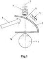
Figure 1 schematically shows an example of the electro-optical device object of the invention, with regard to an eye of application. -
Figure 2 schematically shows the projection of the images of visual stimuli onto the eye of application in the electro-optical device. -
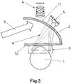
Figure 3 shows the projection of non-visible light onto the eye of application in the electro-optical device. -
Figure 4 shows the capture of the reflections of non-visible light from the eye of application in the electro-optical device. - The object of the invention relates to an electro-optical device intended to explore the functional behavior of an eye (1) before visual stimuli provided by means of the presentation of images in front of the same. The device is based on the use of a structured mirror (2) such that it reflects visible light (400 - 800 nm), but it allows non-visible light from both the infrared range (800 - 1200 nm) and the ultraviolet range (300 - 400 nm) to pass through. To do so, a mirror (1) formed by a body of transparent material, such as "Crown" or "Flint" glass, borosilicate or quartz, with an inner coating is used, for example, of the type known as "cold mirror".
- As observed in
Figure 1 , the mirror (2) is arranged in an inclined position in an axial direction (3) in which an optical system (4) that includes a CMOS or CCD-type sensor capable of capturing non-visible infrared and ultraviolet light is arranged behind said mirror (2). - There is also a light source (5) for emitting non-visible light arranged behind the mirror (2), in an offset position of the axial direction (3), oriented toward an area in which the focusing direction thereof runs in the axial direction (3) in front of the mirror (2); while from a lateral position a projection of images (6) guided to the area where the axial direction (3) passes through the mirror (2) is projected from an optical emitter (not shown).
- Under these conditions, by arranging the electro-optical device in front of an eye (1), such that the eye (1) remains in the area of confluence of the focusing direction of the light source (5) with the axial direction (3) and the gaze direction of the eye (1) coincides with the axial direction (3), the projection of images (6) that is projected onto the inner face of the mirror (2) is reflected according to a projection (7) to the eye (1) in the gaze direction thereof, as observed in
Figure 2 . - Furthermore, the non-visible light emission (8) that the light source (5) emits is projected to an area (9) where the front part of the eye (1) is located, as shown in
Figure 3 , such that said area (9) of projection covers the entire field of movement of the eye (1). - Thus, the eye (1) emits a reflection (10) of the non-visible light received, said reflection (10) being projected in the axial direction (3) to the optical system (4) through the mirror (2), as observed in
Figure 4 . - In doing so, the projection of the reflection (10) that the eye (1) emits to the capturing optical system (4) and the projection (7) of the images of optical stimulus to the eye (1) are both produced in the axial direction (3), and therefore, in the gaze direction of the eye (1). This enables a result of the exploration of the eye (1) to be obtained in order to determine the more specific functional behavior thereof, along with the conventional systems where the reflections of the eye of application are captured from a position that is not aligned with the gaze of the eye.
- The use of non-visible light from the infrared range (800 - 1200 nm) enables algorithms that go beyond the geometric determination of the axis of the vision the eye (1) to be applied with regard to the iris of the eye (1) that is explored, such that greater exploration accuracy is obtained.
- The use of non-visible light from the ultraviolet range (300 - 400 nm) enables, if applicable, an additional value to be obtained regarding the presence of bacteria in the eye (1) that is explored, since most bacteria are fluorescent in this range of non-visible light.
- In the corresponding area in front of the optical system (4), a structure (11) is envisaged in the external face of the mirror (2) that makes a determination like a magnifying glass, which favors the capture of the reflection (10) emitted by the eye (1) by the optical system (4), thus making the operation of the optical device more efficient.
- With regard to the non-visible light emission (8) from the light source (5) and with regard to the reflection (10) that the eye (1) emits to the optical system (4), complementary polarization elements, such as lenses or prisms (not shown), can also be arranged in the outer part of the mirror (2), which achieves a higher quality of the image of the eye (1) that is obtained in the optical system (4) in order to determine the functional behavior of vision.
- In the recommended electro-optical device, the incorporation of a transparent screen (12) is envisaged between the position of the eye (1) of application and the mirror (2) of the device, which provides protection in order to prevent the entry of dust or another type of dirt into the device, constituting a surface that is easy to clean when necessary.
Claims (5)
- An electro-optical device for exploring the behavior of the eyes in response to external visual stimuli, comprising a light source that emits a projection of light onto the eye (1) and an optical system that receives the light reflected in the eye (1) characterized in that it comprises a mirror (2) made up of a transparent body provided with a coating that reflects visible light (400 - 800 nm) and allows non-visible light of the infrared range (800 - 1200 nm) and of the ultraviolet range (300 - 400 nm) to pass through, said mirror (2) being arranged in an inclined position in an axial direction (3) that coincides with the gaze direction of the eye (1), in which an optical system (4) provided with a sensor that captures non-visible infrared and ultraviolet light is located behind the mirror (2) with respect to the position of the eye (1), a light source (5) that projects a non-visible infrared or ultraviolet light emission (8) to the eye (1), the eye emitting a reflection to the optical system (4) in the axial direction (3), while a projection of images (6) in visible light is projected from one side onto the inner face of the mirror (2), the image being reflected to the eye (1) according to a projection in the same axial direction (3).
- The electro-optical device for exploring the behavior of the eyes in response to external visual stimuli according to claim 1, characterized in that in front of the optical system (4), the rear face of the mirror (2) has a structure (11) that makes a determination like a magnifying glass.
- The electro-optical device for exploring the behavior of the eyes in response to external visual stimuli according to any one of the preceding claims, characterized in that with regard to the non-visible light emission (8) from the light source (5) and with regard to the reflection (10) that the eye (1) emits to the optical system (4), complementary polarization elements such as lenses or prisms are arranged in the outer part of the mirror (2).
- The electro-optical device for exploring the behavior of the eyes in response to external visual stimuli according to any one of the preceding claims, characterized in that a transparent screen (12) to protect against dirt is arranged between the position of the eye (1) to be explored and the mirror (2).
- The electro-optical device for exploring the behavior of the eyes in response to external visual stimuli according to any one of the preceding claims, characterized in that the non-visible light emission (8) from the light source (5) is projected onto the eye (1) of application in an area (9) that covers the entire field of movement thereof.
Applications Claiming Priority (2)
| Application Number | Priority Date | Filing Date | Title |
|---|---|---|---|
| ES201531073A ES2603377B1 (en) | 2015-07-21 | 2015-07-21 | ELECTRO-OPTICAL DEVICE FOR EXPLORING EYE BEHAVIOR BEFORE EXTERNAL VISUAL STIMULUS |
| PCT/ES2016/070549 WO2017013296A1 (en) | 2015-07-21 | 2016-07-20 | Electro-optical device for exploring the behaviour of the eyes in response to external visual stimuli |
Publications (2)
| Publication Number | Publication Date |
|---|---|
| EP3326512A1 true EP3326512A1 (en) | 2018-05-30 |
| EP3326512A4 EP3326512A4 (en) | 2019-07-17 |
Family
ID=57833844
Family Applications (1)
| Application Number | Title | Priority Date | Filing Date |
|---|---|---|---|
| EP16827306.8A Withdrawn EP3326512A4 (en) | 2015-07-21 | 2016-07-20 | ELECTRO-OPTICAL DEVICE FOR EXPLORING EYE BEHAVIOR AGAINST EXTERNAL VISUAL STIMULI |
Country Status (3)
| Country | Link |
|---|---|
| EP (1) | EP3326512A4 (en) |
| ES (1) | ES2603377B1 (en) |
| WO (1) | WO2017013296A1 (en) |
Family Cites Families (8)
| Publication number | Priority date | Publication date | Assignee | Title |
|---|---|---|---|---|
| JP4684700B2 (en) * | 2005-03-23 | 2011-05-18 | 株式会社トプコン | Ophthalmic optical characteristic measuring device |
| JP5248926B2 (en) * | 2008-06-05 | 2013-07-31 | 株式会社ニデック | Eye refractive power measuring device |
| JP2013165818A (en) * | 2012-02-15 | 2013-08-29 | Canon Inc | Ophthalmologic apparatus, ophthalmologic control method, and program |
| FR2992843B1 (en) * | 2012-07-06 | 2016-05-06 | Essilor Int | DEVICE AND METHOD FOR MEASURING OBJECTIVE OCULAR REFRACTION AND AT LEAST ONE GEOMETRIC-MORPHOLOGICAL PARAMETER OF AN INDIVIDUAL |
| FR2992844B1 (en) * | 2012-07-06 | 2016-03-18 | Essilor Int | DEVICE AND METHOD FOR MEASURING AT LEAST ONE OBJECTIVE OCULAR REFRACTIVE CHARACTERISTIC OF A SUBJECT FOR A PLURALITY OF VISION DISTANCES |
| ES2444542B1 (en) * | 2012-07-25 | 2014-11-18 | Davalor Consultoria Estrategica Y Tecnologica, S.L | APPARATUS FOR MEASURING THE TOPOGRAPHY AND THICKNESS OF THE CORNEA AND PROCEDURE FOR EMPLOYED MEASUREMENT |
| WO2014043142A1 (en) * | 2012-09-11 | 2014-03-20 | Augmented Vision, Inc. | Compact eye imaging and eye tracking apparatus |
| CN104027067A (en) * | 2014-05-29 | 2014-09-10 | 温州眼视光发展有限公司 | Human eye front tissue coaxial imaging, fixation and lighting system |
-
2015
- 2015-07-21 ES ES201531073A patent/ES2603377B1/en active Active
-
2016
- 2016-07-20 EP EP16827306.8A patent/EP3326512A4/en not_active Withdrawn
- 2016-07-20 WO PCT/ES2016/070549 patent/WO2017013296A1/en not_active Ceased
Also Published As
| Publication number | Publication date |
|---|---|
| ES2603377B1 (en) | 2018-01-09 |
| WO2017013296A1 (en) | 2017-01-26 |
| EP3326512A4 (en) | 2019-07-17 |
| ES2603377A1 (en) | 2017-02-27 |
Similar Documents
| Publication | Publication Date | Title |
|---|---|---|
| US12066635B2 (en) | Stray light suppression for head worn computing | |
| KR101646390B1 (en) | Combination structure of Head up display system and Driven State Monitoring | |
| US9316833B2 (en) | Optical configurations for head worn computing | |
| US9927613B2 (en) | Image display apparatus and head mounted display | |
| US9298002B2 (en) | Optical configurations for head worn computing | |
| CN107852474B (en) | Head-mounted display | |
| IL273397B1 (en) | An augmented reality display with a waveguide configured to capture images of an eye and/or environment | |
| US20210035533A1 (en) | Display device and display method | |
| WO2015012280A1 (en) | Sight line detection device | |
| US10520724B2 (en) | Multi-wavelength head up display systems and methods | |
| JP2018203245A (en) | Display system, electronic mirror system, and mobile body | |
| JP5170072B2 (en) | Head-mounted display device | |
| CN105799593B (en) | Vehicle auxiliary driving device | |
| JP2021017064A (en) | Head-up display device | |
| US12395713B2 (en) | Authentication system and authentication method | |
| ES2603377B1 (en) | ELECTRO-OPTICAL DEVICE FOR EXPLORING EYE BEHAVIOR BEFORE EXTERNAL VISUAL STIMULUS |
Legal Events
| Date | Code | Title | Description |
|---|---|---|---|
| STAA | Information on the status of an ep patent application or granted ep patent |
Free format text: STATUS: THE INTERNATIONAL PUBLICATION HAS BEEN MADE |
|
| PUAI | Public reference made under article 153(3) epc to a published international application that has entered the european phase |
Free format text: ORIGINAL CODE: 0009012 |
|
| STAA | Information on the status of an ep patent application or granted ep patent |
Free format text: STATUS: REQUEST FOR EXAMINATION WAS MADE |
|
| 17P | Request for examination filed |
Effective date: 20180219 |
|
| AK | Designated contracting states |
Kind code of ref document: A1 Designated state(s): AL AT BE BG CH CY CZ DE DK EE ES FI FR GB GR HR HU IE IS IT LI LT LU LV MC MK MT NL NO PL PT RO RS SE SI SK SM TR |
|
| AX | Request for extension of the european patent |
Extension state: BA ME |
|
| DAV | Request for validation of the european patent (deleted) | ||
| DAX | Request for extension of the european patent (deleted) | ||
| A4 | Supplementary search report drawn up and despatched |
Effective date: 20190617 |
|
| RIC1 | Information provided on ipc code assigned before grant |
Ipc: A61B 3/113 20060101ALI20190611BHEP Ipc: A61B 3/107 20060101ALI20190611BHEP Ipc: A61B 3/02 20060101AFI20190611BHEP |
|
| STAA | Information on the status of an ep patent application or granted ep patent |
Free format text: STATUS: THE APPLICATION IS DEEMED TO BE WITHDRAWN |
|
| 18D | Application deemed to be withdrawn |
Effective date: 20200115 |