EP3326503A1 - Hand drying device - Google Patents
Hand drying device Download PDFInfo
- Publication number
- EP3326503A1 EP3326503A1 EP15899570.4A EP15899570A EP3326503A1 EP 3326503 A1 EP3326503 A1 EP 3326503A1 EP 15899570 A EP15899570 A EP 15899570A EP 3326503 A1 EP3326503 A1 EP 3326503A1
- Authority
- EP
- European Patent Office
- Prior art keywords
- intake
- air
- hand dryer
- air inlet
- air passage
- Prior art date
- Legal status (The legal status is an assumption and is not a legal conclusion. Google has not performed a legal analysis and makes no representation as to the accuracy of the status listed.)
- Granted
Links
Images



Classifications
-
- A—HUMAN NECESSITIES
- A47—FURNITURE; DOMESTIC ARTICLES OR APPLIANCES; COFFEE MILLS; SPICE MILLS; SUCTION CLEANERS IN GENERAL
- A47K—SANITARY EQUIPMENT; ACCESSORIES THEREFOR, e.g. TOILET ACCESSORIES
- A47K10/00—Body-drying implements; Toilet paper; Holders therefor
- A47K10/48—Drying by means of hot air
Definitions
- the present invention relates to a hand dryer that blows air to wet hands to dry the hands in a sanitary manner.
- a hand dryer that dries wet hands by blowing air from a nozzle to the wet hands and blowing off water drops.
- a hand dryer includes a high-pressure air-stream generating device for blowing out air from a nozzle to blow water drops off. Operation sound generated during the operation of the high-pressure air-stream generating device becomes noise when it leaks to outside the hand dryer through an air passage that is formed inside the hand dryer.
- a hand dryer disclosed in Patent Literature 1 attempts to reduce noise that leaks to outside thereof by attaching a sound absorbing material to an air passage.
- Patent Literature 1 Japanese Patent No. 3791009
- the present invention has been achieved in view of the above problems, and an object of the present invention is to provide a hand dryer that can reduce generated noise while suppressing increase of its manufacturing cost and deterioration of the reliability of product.
- a hand dryer includes: an air-stream generating device that blows out air, which is taken from a device air inlet, from a device air outlet; an inner housing that accommodates therein the air-stream generating device and has an inner air inlet formed in an intake surface thereof that is opposed to the device air inlet; and an outer housing that accommodates therein the inner housing and the air-stream generating device and has an outer air inlet and an outer air outlet formed therein.
- an intake air passage that connects the outer air inlet and the device air inlet to each other is formed inside the outer housing while including the intake surface and an opposing surface that is opposed to the intake surface as a portion of a wall surface thereof.
- a projection is provided on the opposing surface to project from a region that is opposed to the inner air inlet towards the intake surface, the projection includes a first surface facing an upstream side in the intake air passage.
- FIG. 1 is a perspective view of a hand dryer according to a first embodiment of the present invention.
- FIG. 2 is a front view of the hand dryer according to the first embodiment.
- FIG. 3 is a cross-sectional view of the hand dryer according to the first embodiment taken along a line A-A in FIG. 2 .
- FIG. 4 is a cross-sectional view of the hand dryer according to the first embodiment taken along a line B-B in FIG. 3 .
- FIG. 5 is a cross-sectional view of the hand dryer according to the first embodiment taken along a line C-C in FIG. 4 .
- FIG. 6 is a cross-sectional view illustrating an internal structure of the hand dryer according to the first embodiment in a simplified manner taken along the line A-A in FIG. 2 .
- FIG. 1 is a perspective view of a hand dryer according to a first embodiment of the present invention.
- FIG. 2 is a front view of the hand dryer according to the first embodiment.
- FIG. 3 is a cross-section
- FIG. 7 is a partial enlarged cross-sectional view of the hand dryer according to the first embodiment, in which a portion D illustrated in FIG. 3 is enlarged.
- the left side of the drawing is a front-surface side.
- the lower side of the drawing is the front-surface side.
- a hand dryer 1 includes a high-pressure air-stream generating device 2 as an air-stream generating device, an inner housing 3 that accommodates therein the high-pressure air-stream generating device 2, and an outer housing 4 that accommodates therein the inner housing 3.
- a device air inlet 13 and a device air outlet 14 are formed in the high-pressure air-stream generating device 2.
- the high-pressure air-stream generating device 2 as air is taken in from the device air inlet 13 and the taken air is blown out from the device air outlet 14, a high-pressure air stream is generated.
- the device air inlet 13 is circular in a front view.
- the inner housing 3 accommodates the high-pressure air-stream generating device 2 therein.
- An inner air inlet 7 and an inner air outlet 8 are formed in the inner housing 3.
- the inner air inlet 7 is formed in an intake surface 3a that is opposed to the device air inlet 13 of the high-pressure air-stream generating device 2.
- air is taken into the inner housing 3 through the inner air inlet 7, and the taken air is blown out through the inner air outlet 8.
- the inner air inlet 7 is circular in a front view.
- the inner air inlet 7 is formed to have a larger size than the device air inlet 13 and to be concentric with the device air inlet 13 in a front view.
- the outer housing 4 forms an outline of the hand dryer 1.
- An outer air inlet 5 and nozzles 9 as outer air outlets are formed on the outer housing 4.
- An intake air passage 11 and a discharge air passage 10 are formed inside the outer housing 4.
- the intake air passage 11 is an air passage that connects the outer air inlet 5 and the inner air inlet 7 to each other.
- the discharge air passage 10 is an air passage that connects the inner air outlet 8 and the nozzles 9 to each other.
- a wall surface constituting the intake air passage 11 includes the intake surface 3a of the inner housing 3 and an opposing surface 4a that is opposed to the intake surface 3a.
- the opposing surface 4a is provided in the outer housing 4 in the present embodiment, the opposing surface may be provided in another constituent element from the outer housing 4.
- a projection 12 is provided on the opposing surface 4a, projecting from a region that is opposed to the inner air inlet 7 towards the intake surface 3a.
- the projection 12 includes a first surface 12a facing an upstream side in the intake air passage 11.
- the first surface 12a is located in the region that is opposed to the inner air inlet 7.
- the projection 12 also includes a second surface 12b that extends from a tip of the first surface 12a, that is, an end on the side of the intake surface 3a of the first surface 12a, towards a downstream side in the intake air passage 11 and that is opposed to the intake surface 3a.
- the distance between the second surface 12b and the intake surface 3a in a front-back direction is equal to or less than 1/2 of the distance between the opposing surface 4a and the intake surface 3a in the front-back direction.
- the distance between the tip of the first surface 12a and the intake surface 3a is equal to or less than 1/2 of the distance between the opposing surface 4a and the intake surface 3a.
- the distance between the second surface 12b and the intake surface 3a is not limited to this condition.
- the intake air passage 11 is formed by being bent in a direction in which the intake air passage 11 is away from the opposing surface 4a, in midway to the upstream side in the intake air passage 11 from the inner air inlet 7.
- the portion of the intake air passage 11 bent in the direction in which the intake air passage 11 is away from the opposing surface 4a is called a bent portion 11a.
- the intake air passage 11 is also bent on an upstream side of the bent portion 11a, and the bent portion 11b illustrated in FIG. 5 corresponds to this portion. That is, a plurality of bent portions 11a and 11b are formed in the intake air passage 11.
- the air passing outside the bent portion 11a indicated with the arrow X2 flows at a higher speed than the air passing inside the bent portion 11a indicated with the arrow X1. Therefore, an air stream becomes faster on the side of the opposing surface 4a that is away from the inner air inlet 7, so that air is hardly taken into the inner air inlet 7. That is, the air that having passed by the bent portion 11a is biased towards the side of the opposing surface 4a.
- the air stream is guided to the direction towards the inner air inlet 7 by the first surface 12a provided in the projection 12. Therefore, the air passing outside the bent portion 11a indicated with the arrow X2 is also taken in from the inner air inlet 7 smoothly. That is, the first surface 12a functions as a regulating portion that guides the air that flows while being biased towards the opposing surface 4a, towards the device air inlet 13.
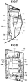
- FIG. 8 is a cross-sectional view of a hand dryer illustrated as a comparative example and corresponding to FIG. 3 .
- FIG. 9 is a cross-sectional view of the hand dryer illustrated as the comparative example and corresponding to FIG. 4 .
- a hand dryer 100 described as the comparative example is different from the hand dryer 1 according to the first embodiment in the configuration of an outer housing 104. More specifically, any projection is not formed in an intake air passage 111. Therefore, the interval between an opposing surface 104a and the intake surface 3a is constant on a downstream side relative to a bent portion 111a.
- the projection 12 is provided in the intake air passage 11 and therefore the side of the opposing surface 4a and the side of the intake surface 3a are asymmetrical with each other. Due to this configuration, the length of an air passage having a constant interval causing resonance can be suppressed, so that noise can be suppressed.
- the first surface 12a is not provided. Therefore, the air stream is hardly guided towards the inner air inlet 7, and it is difficult to cause air to be taken into the inner air inlet 7 smoothly. Further, the air having passed by a front surface of the inner air inlet 7 without being taken into the inner air inlet 7 collides with a downstream end of the intake air passage 11 and circulates in a downstream end portion, thereby causing disturbance of the air stream. The disturbance of the air stream may cause occurrence of noise.
- the air stream is made smooth in the hand dryer 1 according to the first embodiment. Therefore, disturbance of the air stream hardly occurs, so that noise can be suppressed.
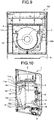
- FIG. 10 is a cross-sectional view of the hand dryer 1 according to a first modification of the first embodiment and corresponding to FIG. 3 .
- FIG. 11 is a cross-sectional view of the hand dryer 1 according to the first modification of the first embodiment and corresponding to FIG. 4 .
- a portion of the first surface 12a has a form of an arc surface, while avoiding a region thereof that is opposed to the device air inlet 13.
- the projection 12 is formed to avoid a region where the device air inlet 13 is projected onto the opposing surface 4a. Due to this configuration, it is possible to allow air to be taken in from the device air inlet 13 more smoothly in the region that is opposed to the device air inlet 13 without narrowing the width of the intake air passage 11.
- a space P surrounded by the intake surface 3a of the inner housing 3, a bottom surface 11c as a third surface of the intake air passage 11, and the second surface 12b functions as an expansion-type silencing space. Therefore, noise generated from the high-pressure air-stream generating device 2 can be reduced. Because the expansion-type silencing space is provided in the vicinity of the inner air inlet 7, noise generated from the high-pressure air-stream generating device 2 can be silenced before being diffused in the intake air passage 11, and therefore a greater silencing effect can be expected. Further, a fourth surface 11d as a top surface is also formed in the intake air passage 11.
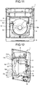
- FIG. 12 is a cross-sectional view of a hand dryer according to a second modification of the first embodiment and corresponding to FIG. 3 .
- FIG. 13 is a cross-sectional view of the hand dryer according to the second modification of the first embodiment and corresponding to FIG. 4 .
- a space P2 serving as an expansion-type silencing space has a passage width that varies depending on a position, and thus a silencing effect can be expected for a wide frequency bandwidth.
- FIGS. 12 and 13 illustrate the projection 12 that is constant in a projecting height, when the projection 12 is formed to have a plurality of projecting heights or a projection is provided on the downstream side relative to the projection 12 to have a different height from the projection 12, the expansion-type silencing space can have a more passage width. Therefore, a silencing effect can be expected for a wider frequency bandwidth.
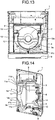
- FIG. 14 is a cross-sectional view of a hand dryer according to a third modification of the first embodiment and corresponding to FIG. 3 .
- FIG. 15 is a cross-sectional view of the hand dryer according to the third modification of the first embodiment and corresponding to FIG. 4 .
- the entire portion of the first surface 12a that is, the entire portion of the projection 12, is provided on a downstream side relative to a region that is opposed to the device air inlet 13.
- the projection 12 it is possible to cause the projection 12 to function as a regulating portion that guides an air stream biased towards the side of the opposing surface 4a of the intake air passage 11 due to the bent portion 11a of the intake air passage 11, towards the device air inlet 13, while avoiding reduction of the passage effective area in association with providing of the projection 12.
- the form of the first surface 12a as viewed from the side thereof may be formed in the form of an arc instead of a flat plane, so as to improve the regulating effect for directing air towards inner air inlet 7.
- FIG. 16 is a diagram of comparison of FFT (First Fourier Transform) waveforms of noise generated in the hand dryer according to the first embodiment and noise generated in the hand dryer illustrated as the comparative example.
- the TFT waveform of the noise generated in the hand dryer 1 according to the first embodiment illustrated in FIG. 16 has been measured by using the hand dryer 1 according to the third modification.
- the hand dryer 1 according to the first embodiment can reduce noise in a wider frequency bandwidth as compared with the hand dryer 100 described as the comparative example. Particularly, the hand dryer 1 according to the first embodiment exhibits an effect of reducing resonance in the intake air passage 11.
- the hand dryer 1 includes the projection 12 that is formed on the opposing surface 4a that is opposed to the intake surface 3a of the inner housing 3 accommodating therein the high-pressure air-stream generating device 2. Therefore, the opposing surface 4a and the intake surface 3a having no projection 12 are asymmetrical with each other, and the distance between these elements is not constant, and thus wall surfaces on which sound is reflected are reduced, so that generation of resonance is suppressed and noise reduction of product can be expected.
- the first surface 12a formed in the projection 12 functions as a regulating portion, so that disturbance of an air stream can be reduced. As a result, noise reduction of product can be expected, while reduction of a pressure loss in the intake air passage 11 is achieved.
- the present invention can be also applied to an intake air passage of a double-sided hand dryer in which the nozzles 9 are arranged to be opposed to one another.
- 1 hand dryer 2 high-pressure air-stream generating device (air-stream generating device), 3 inner housing, 3a intake surface, 4 outer housing, 4a opposing surface, 5 outer air inlet, 7 inner air inlet, 8 inner air outlet, 9 nozzle (outer air outlet), 10 discharge air passage, 11 intake air passage, 11a, 11b bent portion, 11c bottom surface (third surface), 11d top surface (fourth surface), 12 projection, 12a first surface, 12b second surface, 13 device air inlet, 14 device air outlet, 100 hand dryer, 104 outer housing, 104a opposing surface, 111 intake air passage, 111a bent portion.
Landscapes
- Health & Medical Sciences (AREA)
- Public Health (AREA)
- Detail Structures Of Washing Machines And Dryers (AREA)
- Drying Of Solid Materials (AREA)
- Main Body Construction Of Washing Machines And Laundry Dryers (AREA)
Abstract
Description
- The present invention relates to a hand dryer that blows air to wet hands to dry the hands in a sanitary manner.
- There has been used a hand dryer that dries wet hands by blowing air from a nozzle to the wet hands and blowing off water drops. Such a hand dryer includes a high-pressure air-stream generating device for blowing out air from a nozzle to blow water drops off. Operation sound generated during the operation of the high-pressure air-stream generating device becomes noise when it leaks to outside the hand dryer through an air passage that is formed inside the hand dryer. A hand dryer disclosed in
Patent Literature 1 attempts to reduce noise that leaks to outside thereof by attaching a sound absorbing material to an air passage. - Patent Literature 1: Japanese Patent No.
3791009 - However, in the hand dryer disclosed in
Patent Literature 1, attaching of the sound absorbing material increases its manufacturing cost. Further, when the attached sound absorbing material is peeled off, there is a risk that the high-pressure air-stream generating device sucks in the peeled off sound absorbing material and the device fails, so that there is a case where the reliability of the hand dryer is lowered. - The present invention has been achieved in view of the above problems, and an object of the present invention is to provide a hand dryer that can reduce generated noise while suppressing increase of its manufacturing cost and deterioration of the reliability of product.
- In order to solve the above problems and achieve the object, a hand dryer according to the present invention includes: an air-stream generating device that blows out air, which is taken from a device air inlet, from a device air outlet; an inner housing that accommodates therein the air-stream generating device and has an inner air inlet formed in an intake surface thereof that is opposed to the device air inlet; and an outer housing that accommodates therein the inner housing and the air-stream generating device and has an outer air inlet and an outer air outlet formed therein. Further, in the hand dryer, an intake air passage that connects the outer air inlet and the device air inlet to each other is formed inside the outer housing while including the intake surface and an opposing surface that is opposed to the intake surface as a portion of a wall surface thereof. A projection is provided on the opposing surface to project from a region that is opposed to the inner air inlet towards the intake surface, the projection includes a first surface facing an upstream side in the intake air passage.
- According to the hand dryer of the present invention, an effect is obtained where generated noise can be reduced while suppressing increase of its manufacturing cost and deterioration of the reliability of product.
-
-
FIG. 1 is a perspective view of a hand dryer according to a first embodiment of the present invention. -
FIG. 2 is a front view of the hand dryer according to the first embodiment. -
FIG. 3 is a cross-sectional view of the hand dryer according to the first embodiment taken along a line A-A inFIG. 2 . -
FIG. 4 is a cross-sectional view of the hand dryer according to the first embodiment taken along a line B-B inFIG. 3 . -
FIG. 5 is a cross-sectional view of the hand dryer according to the first embodiment taken along a line C-C inFIG. 4 . -
FIG. 6 is a cross-sectional view illustrating an internal structure of the hand dryer according to the first embodiment in a simplified manner taken along the line A-A inFIG. 2 . -
FIG. 7 is a partial enlarged cross-sectional view of the hand dryer according to the first embodiment, in which a portion D illustrated inFIG. 3 is enlarged. -
FIG. 8 is a cross-sectional view of a hand dryer illustrated as a comparative example and corresponding toFIG. 3 . -
FIG. 9 is a cross-sectional view of the hand dryer illustrated as the comparative example and corresponding toFIG. 4 . -
FIG. 10 is a cross-sectional view of a hand dryer according to a first modification of the first embodiment and corresponding toFIG. 3 . -
FIG. 11 is a cross-sectional view of the hand dryer according to the first modification of the first embodiment and corresponding toFIG. 4 . -
FIG. 12 is a cross-sectional view of a hand dryer according to a second modification of the first embodiment and corresponding toFIG. 3 . -
FIG. 13 is a cross-sectional view of the hand dryer according to the second modification of the first embodiment and corresponding toFIG. 4 . -
FIG. 14 is a cross-sectional view of a hand dryer according to a third modification of the first embodiment and corresponding toFIG. 3 . -
FIG. 15 is a cross-sectional view of the hand dryer according to the third modification of the first embodiment and corresponding toFIG. 4 . -
FIG. 16 is a diagram of comparison of FFT (First Fourier Transform) waveforms of noise generated in the hand dryer according to the first embodiment and noise generated in the hand dryer illustrated as the comparative example. - A hand dryer according to an embodiment of the present invention will be described in detail below with reference to the accompanying drawings. The present invention is not limited to the embodiment.
-
FIG. 1 is a perspective view of a hand dryer according to a first embodiment of the present invention.FIG. 2 is a front view of the hand dryer according to the first embodiment.FIG. 3 is a cross-sectional view of the hand dryer according to the first embodiment taken along a line A-A inFIG. 2 .FIG. 4 is a cross-sectional view of the hand dryer according to the first embodiment taken along a line B-B inFIG. 3 .FIG. 5 is a cross-sectional view of the hand dryer according to the first embodiment taken along a line C-C inFIG. 4 .FIG. 6 is a cross-sectional view illustrating an internal structure of the hand dryer according to the first embodiment in a simplified manner taken along the line A-A inFIG. 2 .FIG. 7 is a partial enlarged cross-sectional view of the hand dryer according to the first embodiment, in which a portion D illustrated inFIG. 3 is enlarged. InFIG. 3 , the left side of the drawing is a front-surface side. InFIG. 5 , the lower side of the drawing is the front-surface side. - A
hand dryer 1 includes a high-pressure air-stream generating device 2 as an air-stream generating device, aninner housing 3 that accommodates therein the high-pressure air-stream generating device 2, and anouter housing 4 that accommodates therein theinner housing 3. - A
device air inlet 13 and adevice air outlet 14 are formed in the high-pressure air-stream generating device 2. During the operation of the high-pressure air-stream generating device 2, as air is taken in from thedevice air inlet 13 and the taken air is blown out from thedevice air outlet 14, a high-pressure air stream is generated. As illustrated inFIG. 4 , thedevice air inlet 13 is circular in a front view. - The
inner housing 3 accommodates the high-pressure air-stream generating device 2 therein. Aninner air inlet 7 and aninner air outlet 8 are formed in theinner housing 3. Theinner air inlet 7 is formed in anintake surface 3a that is opposed to thedevice air inlet 13 of the high-pressure air-stream generating device 2. During the operation of the high-pressure air-stream generating device 2, air is taken into theinner housing 3 through theinner air inlet 7, and the taken air is blown out through theinner air outlet 8. As illustrated inFIG. 4 , theinner air inlet 7 is circular in a front view. Theinner air inlet 7 is formed to have a larger size than thedevice air inlet 13 and to be concentric with thedevice air inlet 13 in a front view. - The
outer housing 4 forms an outline of thehand dryer 1. Anouter air inlet 5 andnozzles 9 as outer air outlets are formed on theouter housing 4. Anintake air passage 11 and adischarge air passage 10 are formed inside theouter housing 4. Theintake air passage 11 is an air passage that connects theouter air inlet 5 and theinner air inlet 7 to each other. Thedischarge air passage 10 is an air passage that connects theinner air outlet 8 and thenozzles 9 to each other. With the above configuration of the air passages, during the operation of the high-pressure air-stream generating device 2, air taken into theintake air passage 11 from theouter air inlet 5 passes through thedischarge air path 10 and is blown out from thenozzles 9 as a high-pressure air stream. When wet hands are placed to be opposed to thenozzles 9, water drops on the hands are blown off by the air blown out from thenozzles 9. - A wall surface constituting the
intake air passage 11 includes theintake surface 3a of theinner housing 3 and an opposingsurface 4a that is opposed to theintake surface 3a. Although the opposingsurface 4a is provided in theouter housing 4 in the present embodiment, the opposing surface may be provided in another constituent element from theouter housing 4. - A
projection 12 is provided on the opposingsurface 4a, projecting from a region that is opposed to theinner air inlet 7 towards theintake surface 3a. Theprojection 12 includes afirst surface 12a facing an upstream side in theintake air passage 11. Thefirst surface 12a is located in the region that is opposed to theinner air inlet 7. Theprojection 12 also includes asecond surface 12b that extends from a tip of thefirst surface 12a, that is, an end on the side of theintake surface 3a of thefirst surface 12a, towards a downstream side in theintake air passage 11 and that is opposed to theintake surface 3a. - In the present embodiment, the distance between the
second surface 12b and theintake surface 3a in a front-back direction is equal to or less than 1/2 of the distance between the opposingsurface 4a and theintake surface 3a in the front-back direction. In other words, the distance between the tip of thefirst surface 12a and theintake surface 3a is equal to or less than 1/2 of the distance between the opposingsurface 4a and theintake surface 3a. The distance between thesecond surface 12b and theintake surface 3a is not limited to this condition. - As illustrated in
FIGS. 6 and7 , theintake air passage 11 is formed by being bent in a direction in which theintake air passage 11 is away from the opposingsurface 4a, in midway to the upstream side in theintake air passage 11 from theinner air inlet 7. The portion of theintake air passage 11 bent in the direction in which theintake air passage 11 is away from the opposingsurface 4a is called abent portion 11a. Theintake air passage 11 is also bent on an upstream side of thebent portion 11a, and thebent portion 11b illustrated inFIG. 5 corresponds to this portion. That is, a plurality ofbent portions intake air passage 11. By forming thebent portions intake air passage 11, operation sound of the high-pressure air-stream generating device 2 hardly leaks to outside through theintake air passage 11, and therefore reduction of noise can be achieved. - Further, with the configuration of the
intake air passage 11 of thehand dryer 1 according to the first embodiment, as indicated with an arrow inFIG. 7 , air that flows in parallel to theinner air inlet 7 is guided by thefirst surface 12a to a direction towards theinner air inlet 7, that is, a direction towards thedevice air inlet 13 of the high-pressure air-stream generating device 2. InFIG. 7 , air passing inside thebent portion 11a is indicated with an arrow X1, and air passing outside thereof is indicated with an arrow X2. - As for the air having passed by the
bent portion 11a, the air passing outside thebent portion 11a indicated with the arrow X2 flows at a higher speed than the air passing inside thebent portion 11a indicated with the arrow X1. Therefore, an air stream becomes faster on the side of the opposingsurface 4a that is away from theinner air inlet 7, so that air is hardly taken into theinner air inlet 7. That is, the air that having passed by thebent portion 11a is biased towards the side of the opposingsurface 4a. - However, the air stream is guided to the direction towards the
inner air inlet 7 by thefirst surface 12a provided in theprojection 12. Therefore, the air passing outside thebent portion 11a indicated with the arrow X2 is also taken in from theinner air inlet 7 smoothly. That is, thefirst surface 12a functions as a regulating portion that guides the air that flows while being biased towards the opposingsurface 4a, towards thedevice air inlet 13. - A hand dryer as a comparative example is described here.
FIG. 8 is a cross-sectional view of a hand dryer illustrated as a comparative example and corresponding toFIG. 3 .FIG. 9 is a cross-sectional view of the hand dryer illustrated as the comparative example and corresponding toFIG. 4 . Ahand dryer 100 described as the comparative example is different from thehand dryer 1 according to the first embodiment in the configuration of anouter housing 104. More specifically, any projection is not formed in anintake air passage 111. Therefore, the interval between an opposingsurface 104a and theintake surface 3a is constant on a downstream side relative to abent portion 111a. - In a portion where the interval between the opposing
surface 104a and theintake surface 3a is constant, sound is reflected within theintake air passage 111, so that noise caused by resonance is easily generated. Meanwhile, in thehand dryer 1 according to the first embodiment, theprojection 12 is provided in theintake air passage 11 and therefore the side of the opposingsurface 4a and the side of theintake surface 3a are asymmetrical with each other. Due to this configuration, the length of an air passage having a constant interval causing resonance can be suppressed, so that noise can be suppressed. - Furthermore, in the
hand dryer 100 described in the comparative example, thefirst surface 12a is not provided. Therefore, the air stream is hardly guided towards theinner air inlet 7, and it is difficult to cause air to be taken into theinner air inlet 7 smoothly. Further, the air having passed by a front surface of theinner air inlet 7 without being taken into theinner air inlet 7 collides with a downstream end of theintake air passage 11 and circulates in a downstream end portion, thereby causing disturbance of the air stream. The disturbance of the air stream may cause occurrence of noise. - Meanwhile, as illustrated in
FIG. 7 , the air stream is made smooth in thehand dryer 1 according to the first embodiment. Therefore, disturbance of the air stream hardly occurs, so that noise can be suppressed. - Next, an example of the form of the
projection 12 is described.FIG. 10 is a cross-sectional view of thehand dryer 1 according to a first modification of the first embodiment and corresponding toFIG. 3 .FIG. 11 is a cross-sectional view of thehand dryer 1 according to the first modification of the first embodiment and corresponding toFIG. 4 . - As illustrated in
FIG. 11 , in thehand dryer 1 according to the first modification, a portion of thefirst surface 12a has a form of an arc surface, while avoiding a region thereof that is opposed to thedevice air inlet 13. In other words, theprojection 12 is formed to avoid a region where thedevice air inlet 13 is projected onto the opposingsurface 4a. Due to this configuration, it is possible to allow air to be taken in from thedevice air inlet 13 more smoothly in the region that is opposed to thedevice air inlet 13 without narrowing the width of theintake air passage 11. - Further, a space P surrounded by the
intake surface 3a of theinner housing 3, abottom surface 11c as a third surface of theintake air passage 11, and thesecond surface 12b functions as an expansion-type silencing space. Therefore, noise generated from the high-pressure air-stream generating device 2 can be reduced. Because the expansion-type silencing space is provided in the vicinity of theinner air inlet 7, noise generated from the high-pressure air-stream generating device 2 can be silenced before being diffused in theintake air passage 11, and therefore a greater silencing effect can be expected. Further, afourth surface 11d as a top surface is also formed in theintake air passage 11. -
FIG. 12 is a cross-sectional view of a hand dryer according to a second modification of the first embodiment and corresponding toFIG. 3 .FIG. 13 is a cross-sectional view of the hand dryer according to the second modification of the first embodiment and corresponding toFIG. 4 . - In the
hand dryer 1 according to the second modification, thesecond surface 12b does not reach thebottom surface 11c of theintake air passage 11. Therefore, a space P2 serving as an expansion-type silencing space has a passage width that varies depending on a position, and thus a silencing effect can be expected for a wide frequency bandwidth. WhileFIGS. 12 and13 illustrate theprojection 12 that is constant in a projecting height, when theprojection 12 is formed to have a plurality of projecting heights or a projection is provided on the downstream side relative to theprojection 12 to have a different height from theprojection 12, the expansion-type silencing space can have a more passage width. Therefore, a silencing effect can be expected for a wider frequency bandwidth. -
FIG. 14 is a cross-sectional view of a hand dryer according to a third modification of the first embodiment and corresponding toFIG. 3 .FIG. 15 is a cross-sectional view of the hand dryer according to the third modification of the first embodiment and corresponding toFIG. 4 . In thehand dryer 1 according to the third modification, the entire portion of thefirst surface 12a, that is, the entire portion of theprojection 12, is provided on a downstream side relative to a region that is opposed to thedevice air inlet 13. - In the
hand dryer 1 according to the third modification, it is possible to cause theprojection 12 to function as a regulating portion that guides an air stream biased towards the side of the opposingsurface 4a of theintake air passage 11 due to thebent portion 11a of theintake air passage 11, towards thedevice air inlet 13, while avoiding reduction of the passage effective area in association with providing of theprojection 12. - The form of the
first surface 12a as viewed from the side thereof (the form illustrated in each ofFIGS. 3 ,6 ,10 ,12 , and14 ) may be formed in the form of an arc instead of a flat plane, so as to improve the regulating effect for directing air towardsinner air inlet 7. -
FIG. 16 is a diagram of comparison of FFT (First Fourier Transform) waveforms of noise generated in the hand dryer according to the first embodiment and noise generated in the hand dryer illustrated as the comparative example. The TFT waveform of the noise generated in thehand dryer 1 according to the first embodiment illustrated inFIG. 16 has been measured by using thehand dryer 1 according to the third modification. - As illustrated in
FIG. 16 , thehand dryer 1 according to the first embodiment can reduce noise in a wider frequency bandwidth as compared with thehand dryer 100 described as the comparative example. Particularly, thehand dryer 1 according to the first embodiment exhibits an effect of reducing resonance in theintake air passage 11. - As describe above, the
hand dryer 1 according to the first embodiment includes theprojection 12 that is formed on the opposingsurface 4a that is opposed to theintake surface 3a of theinner housing 3 accommodating therein the high-pressure air-stream generating device 2. Therefore, the opposingsurface 4a and theintake surface 3a having noprojection 12 are asymmetrical with each other, and the distance between these elements is not constant, and thus wall surfaces on which sound is reflected are reduced, so that generation of resonance is suppressed and noise reduction of product can be expected. - Further, the
first surface 12a formed in theprojection 12 functions as a regulating portion, so that disturbance of an air stream can be reduced. As a result, noise reduction of product can be expected, while reduction of a pressure loss in theintake air passage 11 is achieved. - In the first embodiment, although an intake air passage of a single-sided hand dryer in which the
nozzles 9 are arranged in one line has been described as an example, the present invention can be also applied to an intake air passage of a double-sided hand dryer in which thenozzles 9 are arranged to be opposed to one another. - The configurations described in the above embodiment are only examples of the contents of the present invention. The configurations can be combined with other well-known techniques, and a part of each configuration can be omitted or modified without departing from the scope of the present invention.
- 1 hand dryer, 2 high-pressure air-stream generating device (air-stream generating device), 3 inner housing, 3a intake surface, 4 outer housing, 4a opposing surface, 5 outer air inlet, 7 inner air inlet, 8 inner air outlet, 9 nozzle (outer air outlet), 10 discharge air passage, 11 intake air passage, 11a, 11b bent portion, 11c bottom surface (third surface), 11d top surface (fourth surface), 12 projection, 12a first surface, 12b second surface, 13 device air inlet, 14 device air outlet, 100 hand dryer, 104 outer housing, 104a opposing surface, 111 intake air passage, 111a bent portion.
Claims (7)
- A hand dryer comprising:an air-stream generating device that blows out air, taken from a device air inlet, from a device air outlet;an inner housing that accommodates therein the air-stream generating device and has an inner air inlet formed in an intake surface thereof that is opposed to the device air inlet; andan outer housing that accommodates therein the inner housing and the air-stream generating device and has an outer air inlet and an outer air outlet formed therein, whereinan intake air passage that connects the outer air inlet and the device air inlet to each other is formed inside the outer housing while including the intake surface and an opposing surface that is opposed to the intake surface as a portion of a wall surface thereof, anda projection is provided on the opposing surface to project from a region that is opposed to the inner air inlet towards the intake surface, the projection having a first surface facing an upstream side in the intake air passage.
- The hand dryer according to claim 1, wherein the projection has a second surface that extends from a tip of the first surface towards a downstream side in the intake air passage and is opposed to the intake surface.
- The hand dryer according to claim 2, wherein a distance between the second surface and the intake surface is equal to or less than 1/2 of a distance between the opposing surface and the intake surface.
- The hand dryer according to claim 2 or 3, wherein the first surface and the second surface are formed to avoid a region that is opposed to the device air inlet.
- The hand dryer according to claim 4, wherein the first surface is formed on a downstream side in the intake air passage relative to a region that is opposed to the device air inlet.
- The hand dryer according to claim 1, wherein the intake air passage is formed by being bent in a direction in which the intake air passage is away from the opposing surface, in midway to an upstream side in the intake air passage from the inner air inlet.
- The hand dryer according to claim 1, further comprising a third surface and a fourth surface that form the intake air passage and are opposed to each other, wherein
the third surface is provided on a downstream side in the intake air passage relative to the first surface, and
the fourth surface is provided on an upstream side in the intake air passage relative to the first surface.
Applications Claiming Priority (1)
| Application Number | Priority Date | Filing Date | Title |
|---|---|---|---|
| PCT/JP2015/071165 WO2017017736A1 (en) | 2015-07-24 | 2015-07-24 | Hand drying device |
Publications (3)
| Publication Number | Publication Date |
|---|---|
| EP3326503A1 true EP3326503A1 (en) | 2018-05-30 |
| EP3326503A4 EP3326503A4 (en) | 2019-03-13 |
| EP3326503B1 EP3326503B1 (en) | 2021-02-24 |
Family
ID=57884339
Family Applications (1)
| Application Number | Title | Priority Date | Filing Date |
|---|---|---|---|
| EP15899570.4A Active EP3326503B1 (en) | 2015-07-24 | 2015-07-24 | Hand drying device |
Country Status (7)
| Country | Link |
|---|---|
| US (1) | US10561284B2 (en) |
| EP (1) | EP3326503B1 (en) |
| JP (1) | JP6469227B2 (en) |
| CN (1) | CN107847089B (en) |
| AU (1) | AU2015403646B2 (en) |
| TW (1) | TWI618516B (en) |
| WO (1) | WO2017017736A1 (en) |
Cited By (1)
| Publication number | Priority date | Publication date | Assignee | Title |
|---|---|---|---|---|
| US20180213983A1 (en) * | 2015-07-24 | 2018-08-02 | Mitsubishi Electric Corporation | Hand dryer |
Families Citing this family (3)
| Publication number | Priority date | Publication date | Assignee | Title |
|---|---|---|---|---|
| EP3332683B1 (en) | 2015-08-05 | 2020-08-05 | Mitsubishi Electric Corporation | Hand dryer |
| USD853030S1 (en) * | 2015-09-17 | 2019-07-02 | Mitsubishi Electric Corporation | Hand dryer |
| JP7221416B2 (en) * | 2019-03-11 | 2023-02-13 | 美智縦横科技有限責任公司 | ROBOT VACUUM CLEANER AND METHOD OF DETECTING AND CONTROLLING ROBOT PATH CONDITION THEREOF |
Family Cites Families (33)
| Publication number | Priority date | Publication date | Assignee | Title |
|---|---|---|---|---|
| JPS6469227A (en) * | 1987-09-04 | 1989-03-15 | Fujitsu Ltd | Controlling system for dc power source |
| CA2104514C (en) * | 1992-08-25 | 1998-08-25 | Toshio Tatsutani | Hand dryer |
| US5568691A (en) * | 1992-09-22 | 1996-10-29 | Secajo, Ltd. | Hair dryer apparatus adapted for multi-functional usage |
| JP3522829B2 (en) * | 1994-06-09 | 2004-04-26 | 三菱電機株式会社 | Air spray dryer |
| JP3822308B2 (en) | 1997-03-18 | 2006-09-20 | 九州日立マクセル株式会社 | Hot air dryer |
| US6038786A (en) * | 1998-04-16 | 2000-03-21 | Excel Dryer Inc. | Hand dryer |
| JP2000157448A (en) * | 1998-11-27 | 2000-06-13 | Matsushita Seiko Co Ltd | Blowoff nozzle |
| JP2004215879A (en) * | 2003-01-15 | 2004-08-05 | Mitsubishi Electric Corp | Hand drying equipment |
| KR100679556B1 (en) * | 2004-02-17 | 2007-02-07 | 정정균 | Air Spray Hand Dryer |
| WO2005110176A1 (en) * | 2004-05-19 | 2005-11-24 | Toto Ltd. | Hand drying apparatus |
| JP3791009B2 (en) | 2004-09-13 | 2006-06-28 | 東陶機器株式会社 | Hand dryer |
| CN101035455A (en) * | 2005-07-26 | 2007-09-12 | 三菱电机株式会社 | hand dryer |
| GB2428569B (en) * | 2005-07-30 | 2009-04-29 | Dyson Technology Ltd | Dryer |
| GB0515749D0 (en) * | 2005-07-30 | 2005-09-07 | Dyson Technology Ltd | Drying apparatus |
| GB0515754D0 (en) * | 2005-07-30 | 2005-09-07 | Dyson Technology Ltd | Drying apparatus |
| GB0515750D0 (en) * | 2005-07-30 | 2005-09-07 | Dyson Technology Ltd | Drying apparatus |
| WO2007015297A1 (en) * | 2005-08-03 | 2007-02-08 | Mitsubishi Denki Kabushiki Kaisha | Hand dryer |
| US7614160B2 (en) * | 2005-08-18 | 2009-11-10 | Mitsubishi Denki Kabushiki Kaisha | Hand drying apparatus |
| KR100754971B1 (en) * | 2006-02-17 | 2007-09-06 | 이방수 | Hand dryer |
| CN101237804A (en) * | 2006-06-28 | 2008-08-06 | 三菱电机株式会社 | hand dryer |
| CN201194769Y (en) * | 2008-03-06 | 2009-02-18 | 广东松下环境系统有限公司 | Hand dryer |
| EP2277424B1 (en) * | 2008-04-23 | 2017-08-02 | Mitsubishi Electric Corporation | Hand dryer |
| KR101445471B1 (en) * | 2010-07-06 | 2014-09-26 | 미쓰비시덴키 가부시키가이샤 | Hand drying device |
| EP2693927B1 (en) * | 2011-04-07 | 2019-03-27 | Excel Dryer, Inc. | Sanitizing hand dryer |
| JP5780032B2 (en) * | 2011-07-21 | 2015-09-16 | 三菱電機株式会社 | Hand dryer |
| GB201114183D0 (en) * | 2011-08-17 | 2011-10-05 | Dyson Technology Ltd | A hand dryer |
| ES2701313T3 (en) * | 2013-02-13 | 2019-02-21 | Ffuuss 2013 S L | Hand |
| US9125533B2 (en) * | 2013-03-08 | 2015-09-08 | Bobrick Washroom Equipment, Inc. | Dryer and towel dispenser combinations and methods of operating the same |
| MY192193A (en) * | 2014-02-27 | 2022-08-05 | Mitsubishi Electric Corp | Hand dryer apparatus |
| CN106028890B (en) * | 2014-02-27 | 2018-10-02 | 三菱电机株式会社 | Drying apparatus for hands |
| CN107847089B (en) * | 2015-07-24 | 2020-09-08 | 三菱电机株式会社 | hand dryer |
| US10264931B2 (en) * | 2016-09-23 | 2019-04-23 | The Boeing Company | Hand drying systems and methods |
| US10722083B2 (en) * | 2017-10-03 | 2020-07-28 | Thunderhill Investments, LLC | Sanitary forced-air hand dryer |
-
2015
- 2015-07-24 CN CN201580081870.9A patent/CN107847089B/en active Active
- 2015-07-24 AU AU2015403646A patent/AU2015403646B2/en active Active
- 2015-07-24 EP EP15899570.4A patent/EP3326503B1/en active Active
- 2015-07-24 WO PCT/JP2015/071165 patent/WO2017017736A1/en not_active Ceased
- 2015-07-24 JP JP2017530478A patent/JP6469227B2/en active Active
- 2015-07-24 US US15/746,741 patent/US10561284B2/en active Active
-
2016
- 2016-01-25 TW TW105102169A patent/TWI618516B/en active
Cited By (2)
| Publication number | Priority date | Publication date | Assignee | Title |
|---|---|---|---|---|
| US20180213983A1 (en) * | 2015-07-24 | 2018-08-02 | Mitsubishi Electric Corporation | Hand dryer |
| US10561284B2 (en) * | 2015-07-24 | 2020-02-18 | Mitsubishi Electric Corporation | Hand dryer |
Also Published As
| Publication number | Publication date |
|---|---|
| US20180213983A1 (en) | 2018-08-02 |
| AU2015403646B2 (en) | 2018-11-08 |
| AU2015403646A1 (en) | 2018-02-22 |
| TW201703707A (en) | 2017-02-01 |
| CN107847089A (en) | 2018-03-27 |
| CN107847089B (en) | 2020-09-08 |
| EP3326503A4 (en) | 2019-03-13 |
| JPWO2017017736A1 (en) | 2017-10-19 |
| JP6469227B2 (en) | 2019-02-13 |
| WO2017017736A1 (en) | 2017-02-02 |
| TWI618516B (en) | 2018-03-21 |
| EP3326503B1 (en) | 2021-02-24 |
| US10561284B2 (en) | 2020-02-18 |
Similar Documents
| Publication | Publication Date | Title |
|---|---|---|
| EP3326503B1 (en) | Hand drying device | |
| KR102582026B1 (en) | Blower and outdoor unit of air conditioner having the same | |
| KR101597404B1 (en) | Hand dryer device | |
| RU2636974C2 (en) | Fan | |
| JP6221046B2 (en) | Blower | |
| US10047756B2 (en) | Ventilating fan | |
| JP2000157448A (en) | Blowoff nozzle | |
| JP6681539B2 (en) | Blower | |
| JP5694310B2 (en) | Hand dryer | |
| JP7129943B2 (en) | air knife | |
| JP6405529B2 (en) | Blower | |
| JP3854144B2 (en) | Hand dryer | |
| CN107786927B (en) | Loudspeaker system | |
| US20140123649A1 (en) | Acoustic damping system for a combustor of a gas turbine engine | |
| US12031544B2 (en) | Fan | |
| JP2010281227A (en) | Multi-aerofoil centrifugal fan and air conditioner using the same | |
| CN102822492A (en) | Jet flow nozzle and jet engine | |
| JP6265843B2 (en) | Ventilation blower | |
| JP3882409B2 (en) | Pump device with vortex generation prevention device | |
| JP3213020U (en) | Blower | |
| JP7065271B2 (en) | Blower and bathroom heater / dryer equipped with it | |
| JP6617271B2 (en) | Blower | |
| JP2006145942A (en) | Cooling device for video projector | |
| CN106955861A (en) | Guided water jet device | |
| JP5891351B2 (en) | Hand dryer |
Legal Events
| Date | Code | Title | Description |
|---|---|---|---|
| STAA | Information on the status of an ep patent application or granted ep patent |
Free format text: STATUS: THE INTERNATIONAL PUBLICATION HAS BEEN MADE |
|
| PUAI | Public reference made under article 153(3) epc to a published international application that has entered the european phase |
Free format text: ORIGINAL CODE: 0009012 |
|
| STAA | Information on the status of an ep patent application or granted ep patent |
Free format text: STATUS: REQUEST FOR EXAMINATION WAS MADE |
|
| 17P | Request for examination filed |
Effective date: 20180202 |
|
| AK | Designated contracting states |
Kind code of ref document: A1 Designated state(s): AL AT BE BG CH CY CZ DE DK EE ES FI FR GB GR HR HU IE IS IT LI LT LU LV MC MK MT NL NO PL PT RO RS SE SI SK SM TR |
|
| AX | Request for extension of the european patent |
Extension state: BA ME |
|
| DAV | Request for validation of the european patent (deleted) | ||
| DAX | Request for extension of the european patent (deleted) | ||
| A4 | Supplementary search report drawn up and despatched |
Effective date: 20190213 |
|
| RIC1 | Information provided on ipc code assigned before grant |
Ipc: A47K 10/48 20060101AFI20190207BHEP |
|
| STAA | Information on the status of an ep patent application or granted ep patent |
Free format text: STATUS: EXAMINATION IS IN PROGRESS |
|
| 17Q | First examination report despatched |
Effective date: 20191206 |
|
| GRAP | Despatch of communication of intention to grant a patent |
Free format text: ORIGINAL CODE: EPIDOSNIGR1 |
|
| STAA | Information on the status of an ep patent application or granted ep patent |
Free format text: STATUS: GRANT OF PATENT IS INTENDED |
|
| INTG | Intention to grant announced |
Effective date: 20200806 |
|
| GRAS | Grant fee paid |
Free format text: ORIGINAL CODE: EPIDOSNIGR3 |
|
| GRAA | (expected) grant |
Free format text: ORIGINAL CODE: 0009210 |
|
| STAA | Information on the status of an ep patent application or granted ep patent |
Free format text: STATUS: THE PATENT HAS BEEN GRANTED |
|
| AK | Designated contracting states |
Kind code of ref document: B1 Designated state(s): AL AT BE BG CH CY CZ DE DK EE ES FI FR GB GR HR HU IE IS IT LI LT LU LV MC MK MT NL NO PL PT RO RS SE SI SK SM TR |
|
| REG | Reference to a national code |
Ref country code: CH Ref legal event code: EP |
|
| REG | Reference to a national code |
Ref country code: AT Ref legal event code: REF Ref document number: 1363426 Country of ref document: AT Kind code of ref document: T Effective date: 20210315 |
|
| REG | Reference to a national code |
Ref country code: IE Ref legal event code: FG4D |
|
| REG | Reference to a national code |
Ref country code: DE Ref legal event code: R096 Ref document number: 602015066208 Country of ref document: DE |
|
| REG | Reference to a national code |
Ref country code: LT Ref legal event code: MG9D |
|
| REG | Reference to a national code |
Ref country code: NL Ref legal event code: MP Effective date: 20210224 |
|
| PG25 | Lapsed in a contracting state [announced via postgrant information from national office to epo] |
Ref country code: FI Free format text: LAPSE BECAUSE OF FAILURE TO SUBMIT A TRANSLATION OF THE DESCRIPTION OR TO PAY THE FEE WITHIN THE PRESCRIBED TIME-LIMIT Effective date: 20210224 Ref country code: GR Free format text: LAPSE BECAUSE OF FAILURE TO SUBMIT A TRANSLATION OF THE DESCRIPTION OR TO PAY THE FEE WITHIN THE PRESCRIBED TIME-LIMIT Effective date: 20210525 Ref country code: HR Free format text: LAPSE BECAUSE OF FAILURE TO SUBMIT A TRANSLATION OF THE DESCRIPTION OR TO PAY THE FEE WITHIN THE PRESCRIBED TIME-LIMIT Effective date: 20210224 Ref country code: LT Free format text: LAPSE BECAUSE OF FAILURE TO SUBMIT A TRANSLATION OF THE DESCRIPTION OR TO PAY THE FEE WITHIN THE PRESCRIBED TIME-LIMIT Effective date: 20210224 Ref country code: BG Free format text: LAPSE BECAUSE OF FAILURE TO SUBMIT A TRANSLATION OF THE DESCRIPTION OR TO PAY THE FEE WITHIN THE PRESCRIBED TIME-LIMIT Effective date: 20210524 Ref country code: PT Free format text: LAPSE BECAUSE OF FAILURE TO SUBMIT A TRANSLATION OF THE DESCRIPTION OR TO PAY THE FEE WITHIN THE PRESCRIBED TIME-LIMIT Effective date: 20210624 Ref country code: NO Free format text: LAPSE BECAUSE OF FAILURE TO SUBMIT A TRANSLATION OF THE DESCRIPTION OR TO PAY THE FEE WITHIN THE PRESCRIBED TIME-LIMIT Effective date: 20210524 |
|
| REG | Reference to a national code |
Ref country code: AT Ref legal event code: MK05 Ref document number: 1363426 Country of ref document: AT Kind code of ref document: T Effective date: 20210224 |
|
| PG25 | Lapsed in a contracting state [announced via postgrant information from national office to epo] |
Ref country code: SE Free format text: LAPSE BECAUSE OF FAILURE TO SUBMIT A TRANSLATION OF THE DESCRIPTION OR TO PAY THE FEE WITHIN THE PRESCRIBED TIME-LIMIT Effective date: 20210224 Ref country code: LV Free format text: LAPSE BECAUSE OF FAILURE TO SUBMIT A TRANSLATION OF THE DESCRIPTION OR TO PAY THE FEE WITHIN THE PRESCRIBED TIME-LIMIT Effective date: 20210224 Ref country code: NL Free format text: LAPSE BECAUSE OF FAILURE TO SUBMIT A TRANSLATION OF THE DESCRIPTION OR TO PAY THE FEE WITHIN THE PRESCRIBED TIME-LIMIT Effective date: 20210224 Ref country code: PL Free format text: LAPSE BECAUSE OF FAILURE TO SUBMIT A TRANSLATION OF THE DESCRIPTION OR TO PAY THE FEE WITHIN THE PRESCRIBED TIME-LIMIT Effective date: 20210224 Ref country code: RS Free format text: LAPSE BECAUSE OF FAILURE TO SUBMIT A TRANSLATION OF THE DESCRIPTION OR TO PAY THE FEE WITHIN THE PRESCRIBED TIME-LIMIT Effective date: 20210224 |
|
| PG25 | Lapsed in a contracting state [announced via postgrant information from national office to epo] |
Ref country code: IS Free format text: LAPSE BECAUSE OF FAILURE TO SUBMIT A TRANSLATION OF THE DESCRIPTION OR TO PAY THE FEE WITHIN THE PRESCRIBED TIME-LIMIT Effective date: 20210624 |
|
| PG25 | Lapsed in a contracting state [announced via postgrant information from national office to epo] |
Ref country code: SM Free format text: LAPSE BECAUSE OF FAILURE TO SUBMIT A TRANSLATION OF THE DESCRIPTION OR TO PAY THE FEE WITHIN THE PRESCRIBED TIME-LIMIT Effective date: 20210224 Ref country code: AT Free format text: LAPSE BECAUSE OF FAILURE TO SUBMIT A TRANSLATION OF THE DESCRIPTION OR TO PAY THE FEE WITHIN THE PRESCRIBED TIME-LIMIT Effective date: 20210224 Ref country code: CZ Free format text: LAPSE BECAUSE OF FAILURE TO SUBMIT A TRANSLATION OF THE DESCRIPTION OR TO PAY THE FEE WITHIN THE PRESCRIBED TIME-LIMIT Effective date: 20210224 Ref country code: EE Free format text: LAPSE BECAUSE OF FAILURE TO SUBMIT A TRANSLATION OF THE DESCRIPTION OR TO PAY THE FEE WITHIN THE PRESCRIBED TIME-LIMIT Effective date: 20210224 |
|
| REG | Reference to a national code |
Ref country code: DE Ref legal event code: R097 Ref document number: 602015066208 Country of ref document: DE |
|
| PG25 | Lapsed in a contracting state [announced via postgrant information from national office to epo] |
Ref country code: DK Free format text: LAPSE BECAUSE OF FAILURE TO SUBMIT A TRANSLATION OF THE DESCRIPTION OR TO PAY THE FEE WITHIN THE PRESCRIBED TIME-LIMIT Effective date: 20210224 Ref country code: SK Free format text: LAPSE BECAUSE OF FAILURE TO SUBMIT A TRANSLATION OF THE DESCRIPTION OR TO PAY THE FEE WITHIN THE PRESCRIBED TIME-LIMIT Effective date: 20210224 Ref country code: RO Free format text: LAPSE BECAUSE OF FAILURE TO SUBMIT A TRANSLATION OF THE DESCRIPTION OR TO PAY THE FEE WITHIN THE PRESCRIBED TIME-LIMIT Effective date: 20210224 |
|
| PLBE | No opposition filed within time limit |
Free format text: ORIGINAL CODE: 0009261 |
|
| STAA | Information on the status of an ep patent application or granted ep patent |
Free format text: STATUS: NO OPPOSITION FILED WITHIN TIME LIMIT |
|
| PG25 | Lapsed in a contracting state [announced via postgrant information from national office to epo] |
Ref country code: AL Free format text: LAPSE BECAUSE OF FAILURE TO SUBMIT A TRANSLATION OF THE DESCRIPTION OR TO PAY THE FEE WITHIN THE PRESCRIBED TIME-LIMIT Effective date: 20210224 Ref country code: ES Free format text: LAPSE BECAUSE OF FAILURE TO SUBMIT A TRANSLATION OF THE DESCRIPTION OR TO PAY THE FEE WITHIN THE PRESCRIBED TIME-LIMIT Effective date: 20210224 |
|
| 26N | No opposition filed |
Effective date: 20211125 |
|
| PG25 | Lapsed in a contracting state [announced via postgrant information from national office to epo] |
Ref country code: SI Free format text: LAPSE BECAUSE OF FAILURE TO SUBMIT A TRANSLATION OF THE DESCRIPTION OR TO PAY THE FEE WITHIN THE PRESCRIBED TIME-LIMIT Effective date: 20210224 |
|
| REG | Reference to a national code |
Ref country code: CH Ref legal event code: PL |
|
| PG25 | Lapsed in a contracting state [announced via postgrant information from national office to epo] |
Ref country code: MC Free format text: LAPSE BECAUSE OF FAILURE TO SUBMIT A TRANSLATION OF THE DESCRIPTION OR TO PAY THE FEE WITHIN THE PRESCRIBED TIME-LIMIT Effective date: 20210224 |
|
| REG | Reference to a national code |
Ref country code: BE Ref legal event code: MM Effective date: 20210731 |
|
| PG25 | Lapsed in a contracting state [announced via postgrant information from national office to epo] |
Ref country code: LI Free format text: LAPSE BECAUSE OF NON-PAYMENT OF DUE FEES Effective date: 20210731 Ref country code: IT Free format text: LAPSE BECAUSE OF FAILURE TO SUBMIT A TRANSLATION OF THE DESCRIPTION OR TO PAY THE FEE WITHIN THE PRESCRIBED TIME-LIMIT Effective date: 20210224 Ref country code: CH Free format text: LAPSE BECAUSE OF NON-PAYMENT OF DUE FEES Effective date: 20210731 |
|
| PG25 | Lapsed in a contracting state [announced via postgrant information from national office to epo] |
Ref country code: IS Free format text: LAPSE BECAUSE OF FAILURE TO SUBMIT A TRANSLATION OF THE DESCRIPTION OR TO PAY THE FEE WITHIN THE PRESCRIBED TIME-LIMIT Effective date: 20210624 Ref country code: LU Free format text: LAPSE BECAUSE OF NON-PAYMENT OF DUE FEES Effective date: 20210724 Ref country code: FR Free format text: LAPSE BECAUSE OF NON-PAYMENT OF DUE FEES Effective date: 20210731 |
|
| PG25 | Lapsed in a contracting state [announced via postgrant information from national office to epo] |
Ref country code: IE Free format text: LAPSE BECAUSE OF NON-PAYMENT OF DUE FEES Effective date: 20210724 Ref country code: BE Free format text: LAPSE BECAUSE OF NON-PAYMENT OF DUE FEES Effective date: 20210731 |
|
| PG25 | Lapsed in a contracting state [announced via postgrant information from national office to epo] |
Ref country code: HU Free format text: LAPSE BECAUSE OF FAILURE TO SUBMIT A TRANSLATION OF THE DESCRIPTION OR TO PAY THE FEE WITHIN THE PRESCRIBED TIME-LIMIT; INVALID AB INITIO Effective date: 20150724 |
|
| P01 | Opt-out of the competence of the unified patent court (upc) registered |
Effective date: 20230512 |
|
| PG25 | Lapsed in a contracting state [announced via postgrant information from national office to epo] |
Ref country code: CY Free format text: LAPSE BECAUSE OF FAILURE TO SUBMIT A TRANSLATION OF THE DESCRIPTION OR TO PAY THE FEE WITHIN THE PRESCRIBED TIME-LIMIT Effective date: 20210224 |
|
| REG | Reference to a national code |
Ref country code: DE Ref legal event code: R084 Ref document number: 602015066208 Country of ref document: DE |
|
| REG | Reference to a national code |
Ref country code: GB Ref legal event code: 746 Effective date: 20240328 |
|
| PG25 | Lapsed in a contracting state [announced via postgrant information from national office to epo] |
Ref country code: MK Free format text: LAPSE BECAUSE OF FAILURE TO SUBMIT A TRANSLATION OF THE DESCRIPTION OR TO PAY THE FEE WITHIN THE PRESCRIBED TIME-LIMIT Effective date: 20210224 |
|
| PG25 | Lapsed in a contracting state [announced via postgrant information from national office to epo] |
Ref country code: MT Free format text: LAPSE BECAUSE OF FAILURE TO SUBMIT A TRANSLATION OF THE DESCRIPTION OR TO PAY THE FEE WITHIN THE PRESCRIBED TIME-LIMIT Effective date: 20210224 |
|
| PGFP | Annual fee paid to national office [announced via postgrant information from national office to epo] |
Ref country code: GB Payment date: 20250605 Year of fee payment: 11 |
|
| PGFP | Annual fee paid to national office [announced via postgrant information from national office to epo] |
Ref country code: DE Payment date: 20250528 Year of fee payment: 11 |
|
| PG25 | Lapsed in a contracting state [announced via postgrant information from national office to epo] |
Ref country code: TR Free format text: LAPSE BECAUSE OF FAILURE TO SUBMIT A TRANSLATION OF THE DESCRIPTION OR TO PAY THE FEE WITHIN THE PRESCRIBED TIME-LIMIT Effective date: 20210224 |