EP3326189B1 - Mechanical interlock mechanism for electrical devices - Google Patents
Mechanical interlock mechanism for electrical devices Download PDFInfo
- Publication number
- EP3326189B1 EP3326189B1 EP16738789.3A EP16738789A EP3326189B1 EP 3326189 B1 EP3326189 B1 EP 3326189B1 EP 16738789 A EP16738789 A EP 16738789A EP 3326189 B1 EP3326189 B1 EP 3326189B1
- Authority
- EP
- European Patent Office
- Prior art keywords
- track
- section
- shaft
- housing
- electrical devices
- Prior art date
- Legal status (The legal status is an assumption and is not a legal conclusion. Google has not performed a legal analysis and makes no representation as to the accuracy of the status listed.)
- Active
Links
Images

Classifications
-
- H—ELECTRICITY
- H01—ELECTRIC ELEMENTS
- H01H—ELECTRIC SWITCHES; RELAYS; SELECTORS; EMERGENCY PROTECTIVE DEVICES
- H01H31/00—Air-break switches for high tension without arc-extinguishing or arc-preventing means
- H01H31/02—Details
- H01H31/04—Interlocking mechanisms
- H01H31/10—Interlocking mechanisms for interlocking two or more switches
-
- H—ELECTRICITY
- H01—ELECTRIC ELEMENTS
- H01H—ELECTRIC SWITCHES; RELAYS; SELECTORS; EMERGENCY PROTECTIVE DEVICES
- H01H9/00—Details of switching devices, not covered by groups H01H1/00 - H01H7/00
- H01H9/20—Interlocking, locking, or latching mechanisms
- H01H9/26—Interlocking, locking, or latching mechanisms for interlocking two or more switches
-
- H—ELECTRICITY
- H01—ELECTRIC ELEMENTS
- H01H—ELECTRIC SWITCHES; RELAYS; SELECTORS; EMERGENCY PROTECTIVE DEVICES
- H01H3/00—Mechanisms for operating contacts
- H01H3/32—Driving mechanisms, i.e. for transmitting driving force to the contacts
- H01H3/42—Driving mechanisms, i.e. for transmitting driving force to the contacts using cam or eccentric
-
- H—ELECTRICITY
- H01—ELECTRIC ELEMENTS
- H01H—ELECTRIC SWITCHES; RELAYS; SELECTORS; EMERGENCY PROTECTIVE DEVICES
- H01H31/00—Air-break switches for high tension without arc-extinguishing or arc-preventing means
- H01H31/003—Earthing switches
Definitions
- the present invention relates to a mechanical interlock mechanism, in particular a mechanical interlock mechanism for electrical devices.
- a fast ground switch is a special-purpose ground switch which has a certain short circuit current closing capacity; the function thereof is to put the equipment being overhauled into a grounded state, i.e. the equipment being overhauled is switched to a maintenance state.
- an isolating switch can only be operated once a circuit breaker has opened, and a fast ground switch can only perform a closing operation once the isolating switch is in an open state.
- the fast ground switch is connected to the isolating switch on one side, if the isolating switch is closed when the fast ground switch is still closed, i.e. the elements (circuit, power supply etc.) on the other side of the isolating switch are connected to ground, a major short circuit accident will occur, so the isolating switch can only be closed once the fast ground switch has been opened.
- Document D1 ( FR 1 587 240 A ) discloses a mechanical interlock mechanism for electrical devices, comprising a first rotary element 5 with a first track, a second rotary element 8 with a second track, a first linkage element 4, wherein one end being capable of moving along the first track, and a second linkage element 11, wherein one end being capable of moving along the second track.
- the object of the present invention is to provide a mechanical interlock mechanism for electrical devices, which is capable of controlling two electrical devices connected thereto to realize connection or disconnection asynchronously, ensuring the reliability of the interlock operation thereof while reducing the action delay.
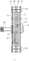
- Figs. 1 and 2 shows a mechanical interlock mechanism according to an embodiment of the present invention, for controlling two different electrical devices in a cooperative manner.
- the mechanical interlock mechanism comprises: a first rotary element 11 and a second rotary element 12.
- the first rotary element 11 and second rotary element 12 can rotate synchronously about the same shaft 30. It is worth pointing out that a first track 111 is also provided on the first rotary element 11, while a second track 121 is also provided on the second rotary element 12.
- the mechanical interlock mechanism also comprises a first linkage element 21 and a second linkage element 22, the first linkage element 21 and the second linkage element 22 each having two ends.
- One of the ends of the first linkage element 21 can move along the first track 111 on the first rotary element 11; one of the ends of the second linkage element 22 can move along the second track 121 on the second rotary element 12.
- the first linkage element 21 passes a first section 111a of the first track 111
- the second linkage element 22 passes a first section 121a of the second track 121
- the first linkage element 21 and the second linkage element 22 are in different states. Specifically, when the first linkage element 21 is in a moving state, the second linkage element 22 is in a stationary state; when the first linkage element 21 is in a stationary state, the second linkage element 22 is in a moving state.
- the first linkage element 21 and second linkage element 22 of the mechanical interlock mechanism are connected to two different electrical devices, for instance a fast ground switch and an isolating switch, respectively in a cooperative manner, so as to be capable of realizing an arrangement whereby when one of the electrical devices is in a connected state, the other electrical device is in a disconnected state, and when one of the electrical devices is in a disconnected state, the other electrical device is in a connected state. Since only one of the electrical devices can be connected each time, while the other is in a disconnected state, it is possible to realize interlock effectively, and realize anticipated disconnection and connection of a circuit through predetermined operations of the first linkage element 21 and second linkage element 22, to ensure electrical safety.
- two different electrical devices for instance a fast ground switch and an isolating switch
- the first track 111 or the second track 121 consists of multiple sections of arc.
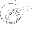
- the first track 111 and second track 121 are both of irregular arcuate shape; the first linkage element 21 and second linkage element 22 perform non-continuous movement in the first track 111 and second track 121 respectively, so as to control electrical devices connected thereto to realize connection or disconnection asynchronously.
- the first track 111 also comprises a second section 111b connected at one end of the first section 111a of the first track 111.
- the first section 111a and second section 111b of the first track 111 are separated from the shaft 30 by different distances. Specifically, the distance between the first section 111a of the first track 111 and the shaft 30 is variable, the distance between the second section 111b of the first track 111 and the shaft 30 is constant, and the distance between the second section 111b of the first track 111 and the shaft 30 is greater than the distance between the first section 111a of the first track 111 and the shaft.
- the first section 111a of the first track 111 is of an irregular arcuate shape, and is separated from the shaft 30 by a gradually increasing distance.
- the second section 111b of the first track 111 is of a regular arcuate shape, and is separated from the shaft 30 by a constant distance.
- the first linkage element 21 is in a moving state in the first section 111a, and in a stationary state in the second section 111b.
- the second track 121 also comprises a second section 121b connected at one end of the first section 121a of the second track 121.
- the first section 121a and second section 121b of the second track 121 are separated from the shaft 30 by different distances. Specifically, the distance between the first section 121a of the second track 121 and the shaft 30 is constant, the distance between the second section 121b of the second track 121 and the shaft 30 is variable, and the distance between the second section 121b of the second track 121 and the shaft 30 is greater than the distance between the first section 121a of the second track 121 and the shaft 30.
- the first section 121a of the second track 121 is of a regular arcuate shape, and is separated from the shaft 30 by a constant distance.
- the second section 121b is of an irregular arcuate shape, and is separated from the shaft 30 by a gradually increasing distance.
- the second linkage element 22 is in a stationary state in the first section 121a, and in a moving state in the second section 121b.
- the central angle corresponding to the first section 111a of the first track 111 is the same as the central angle corresponding to the first section 121a of the second track 121.
- the central angle corresponding to the second section 111b of the first track 111 is the same as the central angle corresponding to the second section 121b of the second track 121.
- the first linkage element 21 will switch from a moving state to a stationary state at a particular moment; at this time, the first linkage element 21 will not stop moving immediately, but continue to move forward a certain distance due to its own inertia. In order to prevent the first rotary element 11 from experiencing certain shock and bumping, it is preferred that a safe movement buffer distance must also be reserved for the first linkage element 21 on the first track 111 of the first rotary element 11.
- the first track 111 also comprises a third section 111c, located at the other end of the first section 111a of the first track 111.
- the distance between the third section 111c of the first track 111 and the shaft 30 is constant, and less than the distance between the second section 111b of the first track 111 and the shaft 30.
- the second linkage element 22 will switch from a moving state to a stationary state at a particular moment; at this time, the second linkage element 22 will not stop moving immediately either, but continue to move forward a certain distance due to its own inertia.
- a safe movement buffer distance must also be reserved for the second linkage element 22 on the second track 121 of the second rotary element 12.
- the second track 121 also comprises a third section 121c, located at another end of the second section 121b of the second track 121.
- the distance between the third section 121c of the second track 121 and the shaft 30 is constant, and greater than the distance between the second section 121b of the second track 121 and the shaft 30.
- the mechanical interlock mechanism of the present invention also comprises a first limiting element, capable of defining the movement direction of the first linkage element 21.
- the mechanical interlock mechanism also comprises a first housing 31, the first limiting element is a third track 311 disposed on the first housing 31, the first housing 31 is located on one side of the first rotary element 11, and another end of the first linkage element 21 can move along the third track 311.
- the third track 311 is of a linear shape extending in a radial direction of the first housing 31.
- the mechanical interlock mechanism preferably also comprises a third housing 33; the third housing 33 is located on another side of the first rotary element 11, and an identical third track 311 is also disposed thereon, as with the first housing 31.
- the third track 311 on the third housing 33 and the third track 311 on the first housing 31 are parallel to each other, and the first housing 31 and third housing 33 are both in a stationary state.
- two ends of the first linkage element 21 are limited in the third track 311 located on the first housing 31 and in the third track 311 located on the third housing 33 respectively; a middle part of the first linkage element 21 is located in the first track 111 on the first rotary element 11.
- the first linkage element 21 is enabled to move according to a predetermined path.
- the limiting element here may also be a locating sleeve, which can cooperate with and limit the movement direction of the first linkage element 21.
- the mechanical interlock mechanism of the present invention also comprises a second limiting element, capable of defining the movement direction of the second linkage element 22.
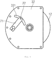
- the mechanical interlock mechanism also comprises a second housing 32, the second limiting element is a fourth track 321 disposed on the second housing 32, the second housing 32 is located on one side of the second rotary element 12, and another end of the second linkage element 22 can move along the fourth track 321.
- the fourth track 321 is of an arcuate shape extending in a radial direction of the second housing 32.
- the mechanical interlock mechanism preferably also comprises a fourth housing 34; the fourth housing 34 is located on another side of the second rotary element, and an identical fourth track 321 is also disposed thereon, as with the second housing 32.
- the fourth track 321 on the second housing 32 and the fourth track 321 on the fourth housing 34 are parallel to each other, and the second housing 32 and fourth housing 34 are both in a stationary state.
- two ends of the second linkage element 22 are limited in the fourth track 321 located on the second housing 32 and in the fourth track 321 located on the fourth housing 34 respectively; a middle part of the second linkage element 22 is located in the second track 121 located on the second rotary element 12.
- the second linkage element 22 is enabled to move according to a predetermined path.
- the first housing 31 and second housing 32 are disposed on an outer side of the first rotary element 11 and the second rotary element 12 respectively.
- the third housing 33 and fourth housing 34 are disposed on an inner side of the first rotary element 11 and the second rotary element 12 respectively.
- the mechanical interlock mechanism for electrical devices of the present invention also comprises: a casing 50.
- the first housing 31, second housing 32, third housing 33 and fourth housing 34 are connected in a fixed manner to the casing 50 by multiple fasteners 51 therebetween.
- the shaft 30 is a drive shaft for supplying a driving force; the first rotary element 11 and second rotary element 12 are fitted round the drive shaft coaxially.
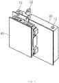
- the mechanical interlock mechanism of the present invention also comprises: a driving force apparatus 40, with an output end of the driving force apparatus being connected to the drive shaft.
- the driving force apparatus 40 is an electric motor. It should be appreciated that a person skilled in the art could also use a hydraulic or pneumatic driving apparatus according to actual circumstances; no restrictions are imposed here.
- the first housing 31, second housing 32, third housing 33 and fourth housing 34 as well as the first rotary element 11 and second rotary element 12 can have the disk-shaped structures shown in the figures.
- the first linkage element 21 and second linkage element 22 may each have a connecting shaft structure. It should be appreciated that the shapes and structures of these components are not unique; a person skilled in the art could make any alterations or changes according to actual requirements, as long as the abovementioned effects of the present invention can be achieved.
- one of the electrical devices for instance a fast ground switch 60
- the first linkage element 21 moves or is stationary, it drives the connecting rod 61 synchronously, so as to control the connection or disconnection of the fast ground switch 60.
- the other electrical device for instance an isolating switch (not shown in the drawing) is connected to the second linkage element 22 via a crank 71. As the second linkage element 22 moves or is stationary, it drives the crank 71 synchronously, so as to control the connection or disconnection of the isolating switch.
- the mechanical interlock mechanism for electrical devices can ensure that only one of two electrical devices is in a connected state, while the other electrical device is in a disconnected state.
- the present invention can control the switching of two electrical devices connected thereto between different states by means of just one mechanical interlock mechanism. This not only lowers the cost thereof, but can also increase the reliability of the interlock operation, and can reduce the action delay; at the same time, accidents caused by operational mistakes can be avoided effectively, ensuring the safety of operation of electrical devices.
Landscapes
- Physics & Mathematics (AREA)
- Electromagnetism (AREA)
- Train Traffic Observation, Control, And Security (AREA)
- Driving Mechanisms And Operating Circuits Of Arc-Extinguishing High-Tension Switches (AREA)
Description
- This patent application claims the priority of
CN patent application 201510424930. 4 - The present invention relates to a mechanical interlock mechanism, in particular a mechanical interlock mechanism for electrical devices.
- As is known, the function of an isolating switch is to disconnect a circuit having no load current, so that there is a clear disconnection point between equipment being overhauled and a power supply, to ensure the safety of maintenance personnel. A fast ground switch is a special-purpose ground switch which has a certain short circuit current closing capacity; the function thereof is to put the equipment being overhauled into a grounded state, i.e. the equipment being overhauled is switched to a maintenance state.
- In view of electrical safety considerations, an isolating switch can only be operated once a circuit breaker has opened, and a fast ground switch can only perform a closing operation once the isolating switch is in an open state. Moreover, since the fast ground switch is connected to the isolating switch on one side, if the isolating switch is closed when the fast ground switch is still closed, i.e. the elements (circuit, power supply etc.) on the other side of the isolating switch are connected to ground, a major short circuit accident will occur, so the isolating switch can only be closed once the fast ground switch has been opened.
- However, since the fast ground switch needs to perform fast closing and opening during operation, whereas the closing and opening operations of the isolating switch are slow, those skilled in the art have developed a novel mechanical interlock mechanism for electrical devices in order to ensure electrical safety and also to ensure coordination and continuity during interlocking operations, such that only one of the fast ground switch and the isolating switch is in a closed state while the other is in an open state.
- Document D1 (
FR 1 587 240 A second linkage element 11, wherein one end being capable of moving along the second track. - The object of the present invention is to provide a mechanical interlock mechanism for electrical devices, which is capable of controlling two electrical devices connected thereto to realize connection or disconnection asynchronously, ensuring the reliability of the interlock operation thereof while reducing the action delay.
- The object is met by the independent claim. Further preferred embodiments are part of the dependent claims.
- The present invention is explained in detail below in conjunction with the accompanying drawings and particular embodiments, wherein:
-
Fig. 1 is a schematic diagram of the internal structure of the mechanical interlock mechanism according to an embodiment of the present invention; -
Fig. 2 is a structural schematic diagram of the first rotary element and second rotary element inFig. 1 ; -
Fig. 3 is a left schematic view ofFig. 1 , wherein an electrical device connected thereto is also shown; -
Fig. 4 is a right schematic view ofFig. 1 ; -
Fig. 5 is a schematic diagram of the external structure of the mechanical interlock mechanism according to another embodiment of the present invention, wherein the driving force apparatus is also shown. - first
rotary element 11
secondrotary element 12
first linkage element 21
second linkage element 22
first housing 31
second housing 32
third housing 33
fourth housing 34
shaft 30
first track 111
first section 111a
second section 111b
third section 111c
second track 121
first section 121a
second section 121b
third section 121c
third track 311
fourth track 321
driving force apparatus 40
casing 50
fastener 51
fast ground switch 60
connectingrod 61
crank 71 - To furnish a clearer understanding of the technical features, object and effects of the present invention, particular embodiments of the present invention are now explained with reference to the accompanying drawings, in which identical labels indicate identical parts. In the drawings representing various embodiments, numbers with the same last two digits represent components with the same structure, or with similar structures but the same function.
- To make the drawings appear uncluttered, only those parts relevant to the present invention are shown schematically in the drawings; they do not represent the actual structure thereof as a product. Furthermore, to make the drawings appear uncluttered for ease of understanding, in the case of components having the same structure or function in certain drawings, only one of these is drawn schematically, or only one is marked.
-
Figs. 1 and2 shows a mechanical interlock mechanism according to an embodiment of the present invention, for controlling two different electrical devices in a cooperative manner. Specifically, the mechanical interlock mechanism comprises: a firstrotary element 11 and a secondrotary element 12. The firstrotary element 11 and secondrotary element 12 can rotate synchronously about thesame shaft 30. It is worth pointing out that afirst track 111 is also provided on the firstrotary element 11, while asecond track 121 is also provided on the secondrotary element 12. - Moreover, the mechanical interlock mechanism also comprises a
first linkage element 21 and asecond linkage element 22, thefirst linkage element 21 and thesecond linkage element 22 each having two ends. One of the ends of thefirst linkage element 21 can move along thefirst track 111 on the firstrotary element 11; one of the ends of thesecond linkage element 22 can move along thesecond track 121 on the secondrotary element 12. - It is worth pointing out that during synchronous rotation of the first
rotary element 11 and secondrotary element 12, thefirst linkage element 21 passes afirst section 111a of thefirst track 111, thesecond linkage element 22 passes afirst section 121a of thesecond track 121, and thefirst linkage element 21 and thesecond linkage element 22 are in different states. Specifically, when thefirst linkage element 21 is in a moving state, thesecond linkage element 22 is in a stationary state; when thefirst linkage element 21 is in a stationary state, thesecond linkage element 22 is in a moving state. - The
first linkage element 21 andsecond linkage element 22 of the mechanical interlock mechanism are connected to two different electrical devices, for instance a fast ground switch and an isolating switch, respectively in a cooperative manner, so as to be capable of realizing an arrangement whereby when one of the electrical devices is in a connected state, the other electrical device is in a disconnected state, and when one of the electrical devices is in a disconnected state, the other electrical device is in a connected state. Since only one of the electrical devices can be connected each time, while the other is in a disconnected state, it is possible to realize interlock effectively, and realize anticipated disconnection and connection of a circuit through predetermined operations of thefirst linkage element 21 andsecond linkage element 22, to ensure electrical safety. - Preferably, the
first track 111 or thesecond track 121 consists of multiple sections of arc. Referring toFig. 2 , thefirst track 111 andsecond track 121 are both of irregular arcuate shape; thefirst linkage element 21 andsecond linkage element 22 perform non-continuous movement in thefirst track 111 andsecond track 121 respectively, so as to control electrical devices connected thereto to realize connection or disconnection asynchronously. - According to a preferred embodiment of the present invention, the
first track 111 also comprises asecond section 111b connected at one end of thefirst section 111a of thefirst track 111. Thefirst section 111a andsecond section 111b of thefirst track 111 are separated from theshaft 30 by different distances. Specifically, the distance between thefirst section 111a of thefirst track 111 and theshaft 30 is variable, the distance between thesecond section 111b of thefirst track 111 and theshaft 30 is constant, and the distance between thesecond section 111b of thefirst track 111 and theshaft 30 is greater than the distance between thefirst section 111a of thefirst track 111 and the shaft. - According to a specific embodiment, the
first section 111a of thefirst track 111 is of an irregular arcuate shape, and is separated from theshaft 30 by a gradually increasing distance. Thesecond section 111b of thefirst track 111 is of a regular arcuate shape, and is separated from theshaft 30 by a constant distance. Thefirst linkage element 21 is in a moving state in thefirst section 111a, and in a stationary state in thesecond section 111b. - The
second track 121 also comprises asecond section 121b connected at one end of thefirst section 121a of thesecond track 121. Thefirst section 121a andsecond section 121b of thesecond track 121 are separated from theshaft 30 by different distances. Specifically, the distance between thefirst section 121a of thesecond track 121 and theshaft 30 is constant, the distance between thesecond section 121b of thesecond track 121 and theshaft 30 is variable, and the distance between thesecond section 121b of thesecond track 121 and theshaft 30 is greater than the distance between thefirst section 121a of thesecond track 121 and theshaft 30. - According to a particular embodiment, the
first section 121a of thesecond track 121 is of a regular arcuate shape, and is separated from theshaft 30 by a constant distance. Thesecond section 121b is of an irregular arcuate shape, and is separated from theshaft 30 by a gradually increasing distance. Thesecond linkage element 22 is in a stationary state in thefirst section 121a, and in a moving state in thesecond section 121b. - It is worth pointing out that in order to ensure continuity of movement between the
first linkage element 21 andsecond linkage element 22, and reduce action delay, the central angle corresponding to thefirst section 111a of thefirst track 111 is the same as the central angle corresponding to thefirst section 121a of thesecond track 121. The central angle corresponding to thesecond section 111b of thefirst track 111 is the same as the central angle corresponding to thesecond section 121b of thesecond track 121. - As the first
rotary element 11 rotates, thefirst linkage element 21 will switch from a moving state to a stationary state at a particular moment; at this time, thefirst linkage element 21 will not stop moving immediately, but continue to move forward a certain distance due to its own inertia. In order to prevent the firstrotary element 11 from experiencing certain shock and bumping, it is preferred that a safe movement buffer distance must also be reserved for thefirst linkage element 21 on thefirst track 111 of the firstrotary element 11. - Specifically, according to a preferred embodiment of the mechanical interlock mechanism of the present invention, the
first track 111 also comprises athird section 111c, located at the other end of thefirst section 111a of thefirst track 111. The distance between thethird section 111c of thefirst track 111 and theshaft 30 is constant, and less than the distance between thesecond section 111b of thefirst track 111 and theshaft 30. - By the same principle, as the second
rotary element 12 rotates, thesecond linkage element 22 will switch from a moving state to a stationary state at a particular moment; at this time, thesecond linkage element 22 will not stop moving immediately either, but continue to move forward a certain distance due to its own inertia. In order to prevent the secondrotary element 12 from experiencing certain shock and bumping, it is preferred that a safe movement buffer distance must also be reserved for thesecond linkage element 22 on thesecond track 121 of the secondrotary element 12. - Specifically, according to a preferred embodiment of the mechanical interlock mechanism of the present invention, the
second track 121 also comprises athird section 121c, located at another end of thesecond section 121b of thesecond track 121. The distance between thethird section 121c of thesecond track 121 and theshaft 30 is constant, and greater than the distance between thesecond section 121b of thesecond track 121 and theshaft 30. - To realize the function of guiding the movement of the
first linkage element 21, and thereby better control an electrical device connected thereto so as to realize anticipated on/off switching, the mechanical interlock mechanism of the present invention also comprises a first limiting element, capable of defining the movement direction of thefirst linkage element 21. According to a specific embodiment of the present invention, the mechanical interlock mechanism also comprises afirst housing 31, the first limiting element is athird track 311 disposed on thefirst housing 31, thefirst housing 31 is located on one side of the firstrotary element 11, and another end of thefirst linkage element 21 can move along thethird track 311. Optionally, thethird track 311 is of a linear shape extending in a radial direction of thefirst housing 31. - It is worth pointing out that in order to achieve better limiting and guiding results while ensuring the mechanical strength of the mechanism, the mechanical interlock mechanism preferably also comprises a
third housing 33; thethird housing 33 is located on another side of the firstrotary element 11, and an identicalthird track 311 is also disposed thereon, as with thefirst housing 31. Thethird track 311 on thethird housing 33 and thethird track 311 on thefirst housing 31 are parallel to each other, and thefirst housing 31 andthird housing 33 are both in a stationary state. In this embodiment, two ends of thefirst linkage element 21 are limited in thethird track 311 located on thefirst housing 31 and in thethird track 311 located on thethird housing 33 respectively; a middle part of thefirst linkage element 21 is located in thefirst track 111 on the firstrotary element 11. Through the joint action of thefirst track 111 and thethird tracks 311, thefirst linkage element 21 is enabled to move according to a predetermined path. It should be understood that in an optional embodiment, the limiting element here may also be a locating sleeve, which can cooperate with and limit the movement direction of thefirst linkage element 21. - To realize the function of guiding the movement of the
second linkage element 22, and thereby better control another electrical device connected thereto so as to realize anticipated on/off switching, the mechanical interlock mechanism of the present invention also comprises a second limiting element, capable of defining the movement direction of thesecond linkage element 22. According to a specific embodiment, the mechanical interlock mechanism also comprises asecond housing 32, the second limiting element is afourth track 321 disposed on thesecond housing 32, thesecond housing 32 is located on one side of the secondrotary element 12, and another end of thesecond linkage element 22 can move along thefourth track 321. Optionally, thefourth track 321 is of an arcuate shape extending in a radial direction of thesecond housing 32. - It is worth pointing out that in order to achieve better limiting and guiding results while ensuring the mechanical strength of the mechanism, the mechanical interlock mechanism preferably also comprises a
fourth housing 34; thefourth housing 34 is located on another side of the second rotary element, and an identicalfourth track 321 is also disposed thereon, as with thesecond housing 32. Thefourth track 321 on thesecond housing 32 and thefourth track 321 on thefourth housing 34 are parallel to each other, and thesecond housing 32 andfourth housing 34 are both in a stationary state. In this embodiment, two ends of thesecond linkage element 22 are limited in thefourth track 321 located on thesecond housing 32 and in thefourth track 321 located on thefourth housing 34 respectively; a middle part of thesecond linkage element 22 is located in thesecond track 121 located on the secondrotary element 12. Through the joint action of thesecond track 121 and thefourth tracks 321, thesecond linkage element 22 is enabled to move according to a predetermined path. - Optionally, as
Fig. 1 shows, thefirst housing 31 andsecond housing 32 are disposed on an outer side of the firstrotary element 11 and the secondrotary element 12 respectively. Thethird housing 33 andfourth housing 34 are disposed on an inner side of the firstrotary element 11 and the secondrotary element 12 respectively. To serve the function of protecting the internal structure, the mechanical interlock mechanism for electrical devices of the present invention also comprises: acasing 50. Thefirst housing 31,second housing 32,third housing 33 andfourth housing 34 are connected in a fixed manner to thecasing 50 bymultiple fasteners 51 therebetween. - Preferably, the
shaft 30 is a drive shaft for supplying a driving force; the firstrotary element 11 and secondrotary element 12 are fitted round the drive shaft coaxially. In order to supply a stable driving force to the mechanical interlock mechanism, referring toFig. 1 , the mechanical interlock mechanism of the present invention also comprises: a drivingforce apparatus 40, with an output end of the driving force apparatus being connected to the drive shaft. Optionally, the drivingforce apparatus 40 is an electric motor. It should be appreciated that a person skilled in the art could also use a hydraulic or pneumatic driving apparatus according to actual circumstances; no restrictions are imposed here. - According to an optional embodiment of the present invention, the
first housing 31,second housing 32,third housing 33 andfourth housing 34 as well as the firstrotary element 11 and secondrotary element 12 can have the disk-shaped structures shown in the figures. Thefirst linkage element 21 andsecond linkage element 22 may each have a connecting shaft structure. It should be appreciated that the shapes and structures of these components are not unique; a person skilled in the art could make any alterations or changes according to actual requirements, as long as the abovementioned effects of the present invention can be achieved. - According to a particular embodiment of the present invention, as
Fig. 3 shows, one of the electrical devices, for instance afast ground switch 60, is connected to thefirst linkage element 21 via a connectingrod 61. As thefirst linkage element 21 moves or is stationary, it drives the connectingrod 61 synchronously, so as to control the connection or disconnection of thefast ground switch 60. The other electrical device, for instance an isolating switch (not shown in the drawing) is connected to thesecond linkage element 22 via acrank 71. As thesecond linkage element 22 moves or is stationary, it drives thecrank 71 synchronously, so as to control the connection or disconnection of the isolating switch. - In summary, during synchronous rotation of the first
rotary element 11 and secondrotary element 12, when thefirst linkage element 21 is in a moving state, thesecond linkage element 22 is in a stationary state; when thefirst linkage element 21 is in a stationary state, thesecond linkage element 22 is in a moving state. Due to mutual constraint of movement between thefirst linkage element 11 and thesecond linkage element 12, the isolating switch is in a connected state when the fast ground switch is in a disconnected state; the fast ground switch is in a connected state when the isolating switch is in a disconnected state. Thus it is possible to reliably and efficiently realize asynchronous on/off switching operations between two electrical devices in a coordinated manner, to prevent the occurrence of erroneous operations. - The mechanical interlock mechanism for electrical devices according to the present invention can ensure that only one of two electrical devices is in a connected state, while the other electrical device is in a disconnected state. In contrast to the prior art, the present invention can control the switching of two electrical devices connected thereto between different states by means of just one mechanical interlock mechanism. This not only lowers the cost thereof, but can also increase the reliability of the interlock operation, and can reduce the action delay; at the same time, accidents caused by operational mistakes can be avoided effectively, ensuring the safety of operation of electrical devices.
Claims (14)
- A mechanical interlock mechanism for electrical devices, comprising:a first rotary element (11), with a first track (111) disposed thereon;a second rotary element (12), with a second track (121) disposed thereon;a first linkage element (21), one end thereof being capable of moving along the first track (111); anda second linkage element (22), one end thereof being capable of moving along the second track (121);characterized in that the first rotary element (11) and the second rotary element (12) are adapted to rotate synchronously about the same shaft (30); such that during synchronous rotation of the first rotary element (11) and the second rotary element (12), the first linkage element (21) passes a first section (111a) of the first track (111), the second linkage element (22) passes a first section (121a) of the second track (121), and the first linkage element (21) and the second linkage element (22) are in different states, wherein one of the first linkage element (21) and the second linkage element (22) is in a moving state, the other is in a stationary state.
- The mechanical interlock mechanism for electrical devices as claimed in claim 1, wherein the first track (111) or the second track (121) consists of multiple sections of arc.
- The mechanical interlock mechanism for electrical devices as claimed in claim 1, wherein the first track (111) also comprises a second section (111b) connected at one end of the first section (111a) of the first track (111), the first section (111a) and second section (111b) of the first track (111) being separated from the shaft (30) by different distances; the second track (121) also comprises a second section (121b) connected at one end of the first section (121a) of the second track (121), the first section (121a) and second section (121b) of the second track (121) being separated from the shaft (30) by different distances.
- The mechanical interlock mechanism for electrical devices as claimed in claim 3, wherein the distance between the first section (111a) of the first track (111) and the shaft (30) is variable, the distance between the second section (111b) of the first track (111) and the shaft (30) is constant, and the distance between the second section (111b) of the first track (111) and the shaft (30) is greater than the distance between the first section (111a) of the first track (111) and the shaft (30); the distance between the first section (121a) of the second track (121) and the shaft (30) is constant, the distance between the second section (121b) of the second track (121) and the shaft (30) is variable, and the distance between the second section (121b) of the second track (121) and the shaft (30) is greater than the distance between the first section (121a) of the second track (121) and the shaft (30).
- The mechanical interlock mechanism for electrical devices as claimed in claim 3 or 4, wherein the central angle corresponding to the first section (111a) of the first track (111) is the same as the central angle corresponding to the first section (121a) of the second track (121), and the central angle corresponding to the second section (111b) of the first track (111) is the same as the central angle corresponding to the second section (121b) of the second track (121).
- The mechanical interlock mechanism for electrical devices as claimed in claim 5, wherein the first track (111) also comprises a third section (111c), connected at the other end of the first section (111a) of the first track (111); the distance between the third section (111c) of the first track (111) and the shaft (30) is constant, and less than the distance between the second section (111b) of the first track (111) and the shaft (30).
- The mechanical interlock mechanism for electrical devices as claimed in claim 5, wherein the second track (121) also comprises a third section (121c), connected at another end of the second section (121b) of the second track (121); the distance between the third section (121c) of the second track (121) and the shaft (30) is constant, and greater than the distance between the second section (121b) of the second track (121) and the shaft (30) .
- The mechanical interlock mechanism for electrical devices as claimed in claim 1, also comprising a first limiting element, capable of defining the movement direction of the first linkage element (21).
- The mechanical interlock mechanism for electrical devices as claimed in claim 8, also comprising a first housing (31), the first limiting element is a third track (311) disposed on the first housing (31), the first housing (31) is located on one side of the first rotary element (11), and another end of the first linkage element (21) can move along the third track (311), wherein the third track (311) is preferably of a linear shape extending in a radial direction of the first housing (31).
- The mechanical interlock mechanism for electrical devices as claimed in claim 9, also comprising a third housing (33) located on another side of the first rotary element (11) and similarly being provided with a third track (311); the third track (311) on the third housing (33) and the third track (311) on the first housing (31) are parallel to each other.
- The mechanical interlock mechanism for electrical devices as claimed in claim 1, also comprising a second limiting element, capable of defining the movement direction of the second linkage element (22).
- The mechanical interlock mechanism for electrical devices as claimed in claim 11, also comprising a second housing (32), the second limiting element is a fourth track (321) disposed on the second housing (32), the second housing (32) is located on one side of the second rotary element (12), and another end of the second linkage element (22) can move along the fourth track (321), wherein the fourth track (321) is preferably of an arcuate shape extending in a radial direction of the second housing (32) .
- The mechanical interlock mechanism for electrical devices as claimed in claim 12, also comprising a fourth housing (34) located on another side of the second rotary element (11) and similarly being provided with a fourth track (321); the fourth track (321) on the second housing (32) and the fourth track (321) on the fourth housing (31) are parallel to each other.
- The mechanical interlock mechanism for electrical devices as claimed in claim 1, wherein the shaft (30) is a drive shaft capable of supplying a driving force; the first rotary element (11) and second rotary element (12) are fitted round the drive shaft coaxially also preferably comprising a driving force apparatus (40), with an output end of the driving force apparatus being connected to the drive shaft.
Applications Claiming Priority (2)
| Application Number | Priority Date | Filing Date | Title |
|---|---|---|---|
| CN201510424930.4A CN106356216B (en) | 2015-07-17 | 2015-07-17 | Mechanical interlocks for electrical equipment |
| PCT/EP2016/066743 WO2017012971A1 (en) | 2015-07-17 | 2016-07-14 | Mechanical interlock mechanism for electrical devices |
Publications (2)
| Publication Number | Publication Date |
|---|---|
| EP3326189A1 EP3326189A1 (en) | 2018-05-30 |
| EP3326189B1 true EP3326189B1 (en) | 2020-08-26 |
Family
ID=56411644
Family Applications (1)
| Application Number | Title | Priority Date | Filing Date |
|---|---|---|---|
| EP16738789.3A Active EP3326189B1 (en) | 2015-07-17 | 2016-07-14 | Mechanical interlock mechanism for electrical devices |
Country Status (5)
| Country | Link |
|---|---|
| EP (1) | EP3326189B1 (en) |
| CN (1) | CN106356216B (en) |
| DK (1) | DK3326189T3 (en) |
| ES (1) | ES2830043T3 (en) |
| WO (1) | WO2017012971A1 (en) |
Families Citing this family (2)
| Publication number | Priority date | Publication date | Assignee | Title |
|---|---|---|---|---|
| CN107946106A (en) * | 2017-12-11 | 2018-04-20 | 浙江上图电气科技有限公司 | A kind of three-phase interlocked mechanical device |
| CN112927965B (en) * | 2021-04-02 | 2025-02-07 | 北京华电瑞通电力工程技术有限公司 | A lower door interlocking device for a high voltage cabinet |
Family Cites Families (6)
| Publication number | Priority date | Publication date | Assignee | Title |
|---|---|---|---|---|
| BE373726A (en) * | ||||
| FR1587240A (en) * | 1968-10-25 | 1970-03-13 | ||
| US4644113A (en) * | 1985-10-09 | 1987-02-17 | Huang L D | Electric safety device |
| CN201663071U (en) * | 2010-04-16 | 2010-12-01 | 浙江森泰电器厂 | An operating mechanism for double power switch |
| CN103531378B (en) * | 2013-09-29 | 2015-08-12 | 江苏德春电力科技有限公司 | Unit switch |
| CN204270930U (en) * | 2014-12-22 | 2015-04-15 | 苏州市吴通光电科技有限公司 | A kind of breaker mechanical mutual interlocking gear |
-
2015
- 2015-07-17 CN CN201510424930.4A patent/CN106356216B/en active Active
-
2016
- 2016-07-14 WO PCT/EP2016/066743 patent/WO2017012971A1/en not_active Ceased
- 2016-07-14 EP EP16738789.3A patent/EP3326189B1/en active Active
- 2016-07-14 DK DK16738789.3T patent/DK3326189T3/en active
- 2016-07-14 ES ES16738789T patent/ES2830043T3/en active Active
Non-Patent Citations (1)
| Title |
|---|
| None * |
Also Published As
| Publication number | Publication date |
|---|---|
| EP3326189A1 (en) | 2018-05-30 |
| CN106356216B (en) | 2019-10-15 |
| CN106356216A (en) | 2017-01-25 |
| WO2017012971A1 (en) | 2017-01-26 |
| ES2830043T3 (en) | 2021-06-02 |
| DK3326189T3 (en) | 2020-11-02 |
Similar Documents
| Publication | Publication Date | Title |
|---|---|---|
| CN102354627B (en) | Three-working-position electric operation mechanism for switching device | |
| EP2838098B1 (en) | Isolating switch | |
| CN103337405B (en) | A three-position mechanism with reclosing and grounding closing functions and an operation method thereof | |
| EP2905853B1 (en) | A switchgear apparatus of the withdrawable type | |
| CN104981887B (en) | Electrical equipment with double-moving contacts including a reset device with two levers | |
| EP2610883B1 (en) | Three-position actuator for switchgear | |
| US7932794B2 (en) | Electro-mechanical actuator, and a high or medium voltage disconnector having such an actuator | |
| CN104392854B (en) | A kind of dual-power conversion switch device | |
| CN101315848B (en) | Double-column horizontal rotation type high-voltage isolation switch | |
| WO2017012971A1 (en) | Mechanical interlock mechanism for electrical devices | |
| CN202678137U (en) | Grounding switch electrically operated mechanism | |
| CN203931860U (en) | A kind of Shou Cao mechanism for circuit breaker | |
| CN104601048A (en) | Operating mechanism of motor starter capable of performing quick breaking | |
| JP2016173960A (en) | Disconnector with earthing switch and switchgear | |
| CN106207837A (en) | Switch cubicle | |
| CN204067278U (en) | A kind of electric operating mechanism of circuit-breaker with instantaneous trip device | |
| CN109994337B (en) | Mechanical interlocking structure and mechanical interlocking device of circuit breaker | |
| CN102723223A (en) | Driving device for switch operation interlocking mechanism | |
| CN204376780U (en) | The operating mechanism of the motor starter of the quick disjunction of energy | |
| CN104505284B (en) | Bidirectional load switchgear | |
| CN201667300U (en) | Impact interlocking device of high-voltage fuse | |
| CN205564573U (en) | Novel two period number change over switch electrical apparatus drives structure | |
| CN203312152U (en) | Double-switching-in-position spring operation mechanism | |
| CN202817893U (en) | Single-coil dual power supply automatic switching device | |
| CN203826312U (en) | Double-pole breaker independent multi-connecting rod tripping device |
Legal Events
| Date | Code | Title | Description |
|---|---|---|---|
| STAA | Information on the status of an ep patent application or granted ep patent |
Free format text: STATUS: THE INTERNATIONAL PUBLICATION HAS BEEN MADE |
|
| PUAI | Public reference made under article 153(3) epc to a published international application that has entered the european phase |
Free format text: ORIGINAL CODE: 0009012 |
|
| STAA | Information on the status of an ep patent application or granted ep patent |
Free format text: STATUS: REQUEST FOR EXAMINATION WAS MADE |
|
| 17P | Request for examination filed |
Effective date: 20180116 |
|
| AK | Designated contracting states |
Kind code of ref document: A1 Designated state(s): AL AT BE BG CH CY CZ DE DK EE ES FI FR GB GR HR HU IE IS IT LI LT LU LV MC MK MT NL NO PL PT RO RS SE SI SK SM TR |
|
| AX | Request for extension of the european patent |
Extension state: BA ME |
|
| DAV | Request for validation of the european patent (deleted) | ||
| DAX | Request for extension of the european patent (deleted) | ||
| STAA | Information on the status of an ep patent application or granted ep patent |
Free format text: STATUS: EXAMINATION IS IN PROGRESS |
|
| 17Q | First examination report despatched |
Effective date: 20190924 |
|
| GRAP | Despatch of communication of intention to grant a patent |
Free format text: ORIGINAL CODE: EPIDOSNIGR1 |
|
| STAA | Information on the status of an ep patent application or granted ep patent |
Free format text: STATUS: GRANT OF PATENT IS INTENDED |
|
| INTG | Intention to grant announced |
Effective date: 20200407 |
|
| GRAS | Grant fee paid |
Free format text: ORIGINAL CODE: EPIDOSNIGR3 |
|
| GRAA | (expected) grant |
Free format text: ORIGINAL CODE: 0009210 |
|
| STAA | Information on the status of an ep patent application or granted ep patent |
Free format text: STATUS: THE PATENT HAS BEEN GRANTED |
|
| AK | Designated contracting states |
Kind code of ref document: B1 Designated state(s): AL AT BE BG CH CY CZ DE DK EE ES FI FR GB GR HR HU IE IS IT LI LT LU LV MC MK MT NL NO PL PT RO RS SE SI SK SM TR |
|
| REG | Reference to a national code |
Ref country code: GB Ref legal event code: FG4D |
|
| REG | Reference to a national code |
Ref country code: CH Ref legal event code: EP |
|
| REG | Reference to a national code |
Ref country code: AT Ref legal event code: REF Ref document number: 1307168 Country of ref document: AT Kind code of ref document: T Effective date: 20200915 |
|
| REG | Reference to a national code |
Ref country code: IE Ref legal event code: FG4D |
|
| REG | Reference to a national code |
Ref country code: DE Ref legal event code: R096 Ref document number: 602016042750 Country of ref document: DE |
|
| REG | Reference to a national code |
Ref country code: CH Ref legal event code: NV Representative=s name: SIEMENS SCHWEIZ AG, CH |
|
| REG | Reference to a national code |
Ref country code: DK Ref legal event code: T3 Effective date: 20201029 |
|
| REG | Reference to a national code |
Ref country code: DE Ref legal event code: R081 Ref document number: 602016042750 Country of ref document: DE Owner name: SIEMENS ENERGY GLOBAL GMBH & CO. KG, DE Free format text: FORMER OWNER: SIEMENS AKTIENGESELLSCHAFT, 80333 MUENCHEN, DE |
|
| REG | Reference to a national code |
Ref country code: LT Ref legal event code: MG4D |
|
| RAP2 | Party data changed (patent owner data changed or rights of a patent transferred) |
Owner name: SIEMENS ENERGY GLOBAL GMBH & CO. KG |
|
| PG25 | Lapsed in a contracting state [announced via postgrant information from national office to epo] |
Ref country code: PT Free format text: LAPSE BECAUSE OF FAILURE TO SUBMIT A TRANSLATION OF THE DESCRIPTION OR TO PAY THE FEE WITHIN THE PRESCRIBED TIME-LIMIT Effective date: 20201228 Ref country code: BG Free format text: LAPSE BECAUSE OF FAILURE TO SUBMIT A TRANSLATION OF THE DESCRIPTION OR TO PAY THE FEE WITHIN THE PRESCRIBED TIME-LIMIT Effective date: 20201126 Ref country code: LT Free format text: LAPSE BECAUSE OF FAILURE TO SUBMIT A TRANSLATION OF THE DESCRIPTION OR TO PAY THE FEE WITHIN THE PRESCRIBED TIME-LIMIT Effective date: 20200826 Ref country code: HR Free format text: LAPSE BECAUSE OF FAILURE TO SUBMIT A TRANSLATION OF THE DESCRIPTION OR TO PAY THE FEE WITHIN THE PRESCRIBED TIME-LIMIT Effective date: 20200826 Ref country code: SE Free format text: LAPSE BECAUSE OF FAILURE TO SUBMIT A TRANSLATION OF THE DESCRIPTION OR TO PAY THE FEE WITHIN THE PRESCRIBED TIME-LIMIT Effective date: 20200826 Ref country code: NO Free format text: LAPSE BECAUSE OF FAILURE TO SUBMIT A TRANSLATION OF THE DESCRIPTION OR TO PAY THE FEE WITHIN THE PRESCRIBED TIME-LIMIT Effective date: 20201126 Ref country code: FI Free format text: LAPSE BECAUSE OF FAILURE TO SUBMIT A TRANSLATION OF THE DESCRIPTION OR TO PAY THE FEE WITHIN THE PRESCRIBED TIME-LIMIT Effective date: 20200826 Ref country code: GR Free format text: LAPSE BECAUSE OF FAILURE TO SUBMIT A TRANSLATION OF THE DESCRIPTION OR TO PAY THE FEE WITHIN THE PRESCRIBED TIME-LIMIT Effective date: 20201127 |
|
| REG | Reference to a national code |
Ref country code: NL Ref legal event code: MP Effective date: 20200826 |
|
| REG | Reference to a national code |
Ref country code: AT Ref legal event code: MK05 Ref document number: 1307168 Country of ref document: AT Kind code of ref document: T Effective date: 20200826 |
|
| PG25 | Lapsed in a contracting state [announced via postgrant information from national office to epo] |
Ref country code: PL Free format text: LAPSE BECAUSE OF FAILURE TO SUBMIT A TRANSLATION OF THE DESCRIPTION OR TO PAY THE FEE WITHIN THE PRESCRIBED TIME-LIMIT Effective date: 20200826 Ref country code: RS Free format text: LAPSE BECAUSE OF FAILURE TO SUBMIT A TRANSLATION OF THE DESCRIPTION OR TO PAY THE FEE WITHIN THE PRESCRIBED TIME-LIMIT Effective date: 20200826 Ref country code: NL Free format text: LAPSE BECAUSE OF FAILURE TO SUBMIT A TRANSLATION OF THE DESCRIPTION OR TO PAY THE FEE WITHIN THE PRESCRIBED TIME-LIMIT Effective date: 20200826 Ref country code: LV Free format text: LAPSE BECAUSE OF FAILURE TO SUBMIT A TRANSLATION OF THE DESCRIPTION OR TO PAY THE FEE WITHIN THE PRESCRIBED TIME-LIMIT Effective date: 20200826 Ref country code: IS Free format text: LAPSE BECAUSE OF FAILURE TO SUBMIT A TRANSLATION OF THE DESCRIPTION OR TO PAY THE FEE WITHIN THE PRESCRIBED TIME-LIMIT Effective date: 20201226 |
|
| PG25 | Lapsed in a contracting state [announced via postgrant information from national office to epo] |
Ref country code: CZ Free format text: LAPSE BECAUSE OF FAILURE TO SUBMIT A TRANSLATION OF THE DESCRIPTION OR TO PAY THE FEE WITHIN THE PRESCRIBED TIME-LIMIT Effective date: 20200826 Ref country code: RO Free format text: LAPSE BECAUSE OF FAILURE TO SUBMIT A TRANSLATION OF THE DESCRIPTION OR TO PAY THE FEE WITHIN THE PRESCRIBED TIME-LIMIT Effective date: 20200826 Ref country code: SM Free format text: LAPSE BECAUSE OF FAILURE TO SUBMIT A TRANSLATION OF THE DESCRIPTION OR TO PAY THE FEE WITHIN THE PRESCRIBED TIME-LIMIT Effective date: 20200826 Ref country code: EE Free format text: LAPSE BECAUSE OF FAILURE TO SUBMIT A TRANSLATION OF THE DESCRIPTION OR TO PAY THE FEE WITHIN THE PRESCRIBED TIME-LIMIT Effective date: 20200826 |
|
| REG | Reference to a national code |
Ref country code: DE Ref legal event code: R097 Ref document number: 602016042750 Country of ref document: DE |
|
| PG25 | Lapsed in a contracting state [announced via postgrant information from national office to epo] |
Ref country code: AL Free format text: LAPSE BECAUSE OF FAILURE TO SUBMIT A TRANSLATION OF THE DESCRIPTION OR TO PAY THE FEE WITHIN THE PRESCRIBED TIME-LIMIT Effective date: 20200826 Ref country code: AT Free format text: LAPSE BECAUSE OF FAILURE TO SUBMIT A TRANSLATION OF THE DESCRIPTION OR TO PAY THE FEE WITHIN THE PRESCRIBED TIME-LIMIT Effective date: 20200826 |
|
| REG | Reference to a national code |
Ref country code: ES Ref legal event code: FG2A Ref document number: 2830043 Country of ref document: ES Kind code of ref document: T3 Effective date: 20210602 |
|
| PG25 | Lapsed in a contracting state [announced via postgrant information from national office to epo] |
Ref country code: SK Free format text: LAPSE BECAUSE OF FAILURE TO SUBMIT A TRANSLATION OF THE DESCRIPTION OR TO PAY THE FEE WITHIN THE PRESCRIBED TIME-LIMIT Effective date: 20200826 |
|
| PLBE | No opposition filed within time limit |
Free format text: ORIGINAL CODE: 0009261 |
|
| STAA | Information on the status of an ep patent application or granted ep patent |
Free format text: STATUS: NO OPPOSITION FILED WITHIN TIME LIMIT |
|
| 26N | No opposition filed |
Effective date: 20210527 |
|
| PG25 | Lapsed in a contracting state [announced via postgrant information from national office to epo] |
Ref country code: SI Free format text: LAPSE BECAUSE OF FAILURE TO SUBMIT A TRANSLATION OF THE DESCRIPTION OR TO PAY THE FEE WITHIN THE PRESCRIBED TIME-LIMIT Effective date: 20200826 |
|
| REG | Reference to a national code |
Ref country code: GB Ref legal event code: 732E Free format text: REGISTERED BETWEEN 20211202 AND 20211209 |
|
| PG25 | Lapsed in a contracting state [announced via postgrant information from national office to epo] |
Ref country code: MC Free format text: LAPSE BECAUSE OF FAILURE TO SUBMIT A TRANSLATION OF THE DESCRIPTION OR TO PAY THE FEE WITHIN THE PRESCRIBED TIME-LIMIT Effective date: 20200826 |
|
| REG | Reference to a national code |
Ref country code: BE Ref legal event code: MM Effective date: 20210731 |
|
| PG25 | Lapsed in a contracting state [announced via postgrant information from national office to epo] |
Ref country code: LU Free format text: LAPSE BECAUSE OF NON-PAYMENT OF DUE FEES Effective date: 20210714 |
|
| PG25 | Lapsed in a contracting state [announced via postgrant information from national office to epo] |
Ref country code: IE Free format text: LAPSE BECAUSE OF NON-PAYMENT OF DUE FEES Effective date: 20210714 Ref country code: BE Free format text: LAPSE BECAUSE OF NON-PAYMENT OF DUE FEES Effective date: 20210731 |
|
| PG25 | Lapsed in a contracting state [announced via postgrant information from national office to epo] |
Ref country code: HU Free format text: LAPSE BECAUSE OF FAILURE TO SUBMIT A TRANSLATION OF THE DESCRIPTION OR TO PAY THE FEE WITHIN THE PRESCRIBED TIME-LIMIT; INVALID AB INITIO Effective date: 20160714 |
|
| PG25 | Lapsed in a contracting state [announced via postgrant information from national office to epo] |
Ref country code: CY Free format text: LAPSE BECAUSE OF FAILURE TO SUBMIT A TRANSLATION OF THE DESCRIPTION OR TO PAY THE FEE WITHIN THE PRESCRIBED TIME-LIMIT Effective date: 20200826 |
|
| PG25 | Lapsed in a contracting state [announced via postgrant information from national office to epo] |
Ref country code: MK Free format text: LAPSE BECAUSE OF FAILURE TO SUBMIT A TRANSLATION OF THE DESCRIPTION OR TO PAY THE FEE WITHIN THE PRESCRIBED TIME-LIMIT Effective date: 20200826 |
|
| PG25 | Lapsed in a contracting state [announced via postgrant information from national office to epo] |
Ref country code: MT Free format text: LAPSE BECAUSE OF FAILURE TO SUBMIT A TRANSLATION OF THE DESCRIPTION OR TO PAY THE FEE WITHIN THE PRESCRIBED TIME-LIMIT Effective date: 20200826 |
|
| PGFP | Annual fee paid to national office [announced via postgrant information from national office to epo] |
Ref country code: ES Payment date: 20250811 Year of fee payment: 10 |
|
| PGFP | Annual fee paid to national office [announced via postgrant information from national office to epo] |
Ref country code: DK Payment date: 20250725 Year of fee payment: 10 Ref country code: DE Payment date: 20250728 Year of fee payment: 10 |
|
| PGFP | Annual fee paid to national office [announced via postgrant information from national office to epo] |
Ref country code: IT Payment date: 20250721 Year of fee payment: 10 |
|
| PGFP | Annual fee paid to national office [announced via postgrant information from national office to epo] |
Ref country code: GB Payment date: 20250722 Year of fee payment: 10 |
|
| PGFP | Annual fee paid to national office [announced via postgrant information from national office to epo] |
Ref country code: FR Payment date: 20250725 Year of fee payment: 10 |
|
| PGFP | Annual fee paid to national office [announced via postgrant information from national office to epo] |
Ref country code: CH Payment date: 20250801 Year of fee payment: 10 |
|
| PG25 | Lapsed in a contracting state [announced via postgrant information from national office to epo] |
Ref country code: TR Free format text: LAPSE BECAUSE OF FAILURE TO SUBMIT A TRANSLATION OF THE DESCRIPTION OR TO PAY THE FEE WITHIN THE PRESCRIBED TIME-LIMIT Effective date: 20200826 |