EP3325406B1 - Process for the thermal decomposition of ammonia and reactor for carrying out said process - Google Patents
Process for the thermal decomposition of ammonia and reactor for carrying out said process Download PDFInfo
- Publication number
- EP3325406B1 EP3325406B1 EP16828614.4A EP16828614A EP3325406B1 EP 3325406 B1 EP3325406 B1 EP 3325406B1 EP 16828614 A EP16828614 A EP 16828614A EP 3325406 B1 EP3325406 B1 EP 3325406B1
- Authority
- EP
- European Patent Office
- Prior art keywords
- ammonia
- nickel
- porous ceramic
- ceramic layer
- reactor
- Prior art date
- Legal status (The legal status is an assumption and is not a legal conclusion. Google has not performed a legal analysis and makes no representation as to the accuracy of the status listed.)
- Active
Links
Images

Classifications
-
- B—PERFORMING OPERATIONS; TRANSPORTING
- B01—PHYSICAL OR CHEMICAL PROCESSES OR APPARATUS IN GENERAL
- B01J—CHEMICAL OR PHYSICAL PROCESSES, e.g. CATALYSIS OR COLLOID CHEMISTRY; THEIR RELEVANT APPARATUS
- B01J8/00—Chemical or physical processes in general, conducted in the presence of fluids and solid particles; Apparatus for such processes
-
- B—PERFORMING OPERATIONS; TRANSPORTING
- B01—PHYSICAL OR CHEMICAL PROCESSES OR APPARATUS IN GENERAL
- B01J—CHEMICAL OR PHYSICAL PROCESSES, e.g. CATALYSIS OR COLLOID CHEMISTRY; THEIR RELEVANT APPARATUS
- B01J12/00—Chemical processes in general for reacting gaseous media with gaseous media; Apparatus specially adapted therefor
- B01J12/007—Chemical processes in general for reacting gaseous media with gaseous media; Apparatus specially adapted therefor in the presence of catalytically active bodies, e.g. porous plates
-
- B—PERFORMING OPERATIONS; TRANSPORTING
- B01—PHYSICAL OR CHEMICAL PROCESSES OR APPARATUS IN GENERAL
- B01J—CHEMICAL OR PHYSICAL PROCESSES, e.g. CATALYSIS OR COLLOID CHEMISTRY; THEIR RELEVANT APPARATUS
- B01J16/00—Chemical processes in general for reacting liquids with non- particulate solids, e.g. sheet material; Apparatus specially adapted therefor
- B01J16/005—Chemical processes in general for reacting liquids with non- particulate solids, e.g. sheet material; Apparatus specially adapted therefor in the presence of catalytically active bodies, e.g. porous plates
-
- B—PERFORMING OPERATIONS; TRANSPORTING
- B01—PHYSICAL OR CHEMICAL PROCESSES OR APPARATUS IN GENERAL
- B01J—CHEMICAL OR PHYSICAL PROCESSES, e.g. CATALYSIS OR COLLOID CHEMISTRY; THEIR RELEVANT APPARATUS
- B01J19/00—Chemical, physical or physico-chemical processes in general; Their relevant apparatus
- B01J19/0053—Details of the reactor
-
- B—PERFORMING OPERATIONS; TRANSPORTING
- B01—PHYSICAL OR CHEMICAL PROCESSES OR APPARATUS IN GENERAL
- B01J—CHEMICAL OR PHYSICAL PROCESSES, e.g. CATALYSIS OR COLLOID CHEMISTRY; THEIR RELEVANT APPARATUS
- B01J19/00—Chemical, physical or physico-chemical processes in general; Their relevant apparatus
- B01J19/24—Stationary reactors without moving elements inside
- B01J19/248—Reactors comprising multiple separated flow channels
- B01J19/249—Plate-type reactors
-
- C—CHEMISTRY; METALLURGY
- C01—INORGANIC CHEMISTRY
- C01B—NON-METALLIC ELEMENTS; COMPOUNDS THEREOF; METALLOIDS OR COMPOUNDS THEREOF NOT COVERED BY SUBCLASS C01C
- C01B3/00—Hydrogen; Gaseous mixtures containing hydrogen; Separation of hydrogen from mixtures containing it; Purification of hydrogen; Reversible storage of hydrogen
- C01B3/02—Production of hydrogen; Production of gaseous mixtures containing hydrogen
- C01B3/04—Production of hydrogen; Production of gaseous mixtures containing hydrogen by decomposition of inorganic compounds
-
- C—CHEMISTRY; METALLURGY
- C01—INORGANIC CHEMISTRY
- C01B—NON-METALLIC ELEMENTS; COMPOUNDS THEREOF; METALLOIDS OR COMPOUNDS THEREOF NOT COVERED BY SUBCLASS C01C
- C01B3/00—Hydrogen; Gaseous mixtures containing hydrogen; Separation of hydrogen from mixtures containing it; Purification of hydrogen; Reversible storage of hydrogen
- C01B3/02—Production of hydrogen; Production of gaseous mixtures containing hydrogen
- C01B3/04—Production of hydrogen; Production of gaseous mixtures containing hydrogen by decomposition of inorganic compounds
- C01B3/047—Decomposition of ammonia
-
- H—ELECTRICITY
- H01—ELECTRIC ELEMENTS
- H01M—PROCESSES OR MEANS, e.g. BATTERIES, FOR THE DIRECT CONVERSION OF CHEMICAL ENERGY INTO ELECTRICAL ENERGY
- H01M8/00—Fuel cells; Manufacture thereof
- H01M8/06—Combination of fuel cells with means for production of reactants or for treatment of residues
- H01M8/0606—Combination of fuel cells with means for production of reactants or for treatment of residues with means for production of gaseous reactants
-
- B—PERFORMING OPERATIONS; TRANSPORTING
- B01—PHYSICAL OR CHEMICAL PROCESSES OR APPARATUS IN GENERAL
- B01J—CHEMICAL OR PHYSICAL PROCESSES, e.g. CATALYSIS OR COLLOID CHEMISTRY; THEIR RELEVANT APPARATUS
- B01J2219/00—Chemical, physical or physico-chemical processes in general; Their relevant apparatus
- B01J2219/00049—Controlling or regulating processes
- B01J2219/00051—Controlling the temperature
-
- B—PERFORMING OPERATIONS; TRANSPORTING
- B01—PHYSICAL OR CHEMICAL PROCESSES OR APPARATUS IN GENERAL
- B01J—CHEMICAL OR PHYSICAL PROCESSES, e.g. CATALYSIS OR COLLOID CHEMISTRY; THEIR RELEVANT APPARATUS
- B01J2219/00—Chemical, physical or physico-chemical processes in general; Their relevant apparatus
- B01J2219/02—Apparatus characterised by their chemically-resistant properties
- B01J2219/0204—Apparatus characterised by their chemically-resistant properties comprising coatings on the surfaces in direct contact with the reactive components
- B01J2219/0218—Apparatus characterised by their chemically-resistant properties comprising coatings on the surfaces in direct contact with the reactive components of ceramic
-
- B—PERFORMING OPERATIONS; TRANSPORTING
- B01—PHYSICAL OR CHEMICAL PROCESSES OR APPARATUS IN GENERAL
- B01J—CHEMICAL OR PHYSICAL PROCESSES, e.g. CATALYSIS OR COLLOID CHEMISTRY; THEIR RELEVANT APPARATUS
- B01J2219/00—Chemical, physical or physico-chemical processes in general; Their relevant apparatus
- B01J2219/02—Apparatus characterised by their chemically-resistant properties
- B01J2219/025—Apparatus characterised by their chemically-resistant properties characterised by the construction materials of the reactor vessel proper
- B01J2219/0277—Metal based
- B01J2219/0286—Steel
-
- B—PERFORMING OPERATIONS; TRANSPORTING
- B01—PHYSICAL OR CHEMICAL PROCESSES OR APPARATUS IN GENERAL
- B01J—CHEMICAL OR PHYSICAL PROCESSES, e.g. CATALYSIS OR COLLOID CHEMISTRY; THEIR RELEVANT APPARATUS
- B01J2219/00—Chemical, physical or physico-chemical processes in general; Their relevant apparatus
- B01J2219/08—Processes employing the direct application of electric or wave energy, or particle radiation; Apparatus therefor
- B01J2219/0873—Materials to be treated
- B01J2219/0875—Gas
-
- B—PERFORMING OPERATIONS; TRANSPORTING
- B01—PHYSICAL OR CHEMICAL PROCESSES OR APPARATUS IN GENERAL
- B01J—CHEMICAL OR PHYSICAL PROCESSES, e.g. CATALYSIS OR COLLOID CHEMISTRY; THEIR RELEVANT APPARATUS
- B01J2219/00—Chemical, physical or physico-chemical processes in general; Their relevant apparatus
- B01J2219/24—Stationary reactors without moving elements inside
- B01J2219/2401—Reactors comprising multiple separate flow channels
- B01J2219/245—Plate-type reactors
- B01J2219/2451—Geometry of the reactor
- B01J2219/2453—Plates arranged in parallel
-
- B—PERFORMING OPERATIONS; TRANSPORTING
- B01—PHYSICAL OR CHEMICAL PROCESSES OR APPARATUS IN GENERAL
- B01J—CHEMICAL OR PHYSICAL PROCESSES, e.g. CATALYSIS OR COLLOID CHEMISTRY; THEIR RELEVANT APPARATUS
- B01J2219/00—Chemical, physical or physico-chemical processes in general; Their relevant apparatus
- B01J2219/24—Stationary reactors without moving elements inside
- B01J2219/2401—Reactors comprising multiple separate flow channels
- B01J2219/245—Plate-type reactors
- B01J2219/2451—Geometry of the reactor
- B01J2219/2456—Geometry of the plates
- B01J2219/2458—Flat plates, i.e. plates which are not corrugated or otherwise structured, e.g. plates with cylindrical shape
-
- B—PERFORMING OPERATIONS; TRANSPORTING
- B01—PHYSICAL OR CHEMICAL PROCESSES OR APPARATUS IN GENERAL
- B01J—CHEMICAL OR PHYSICAL PROCESSES, e.g. CATALYSIS OR COLLOID CHEMISTRY; THEIR RELEVANT APPARATUS
- B01J2219/00—Chemical, physical or physico-chemical processes in general; Their relevant apparatus
- B01J2219/24—Stationary reactors without moving elements inside
- B01J2219/2401—Reactors comprising multiple separate flow channels
- B01J2219/245—Plate-type reactors
- B01J2219/2451—Geometry of the reactor
- B01J2219/2456—Geometry of the plates
- B01J2219/2459—Corrugated plates
-
- B—PERFORMING OPERATIONS; TRANSPORTING
- B01—PHYSICAL OR CHEMICAL PROCESSES OR APPARATUS IN GENERAL
- B01J—CHEMICAL OR PHYSICAL PROCESSES, e.g. CATALYSIS OR COLLOID CHEMISTRY; THEIR RELEVANT APPARATUS
- B01J2219/00—Chemical, physical or physico-chemical processes in general; Their relevant apparatus
- B01J2219/24—Stationary reactors without moving elements inside
- B01J2219/2401—Reactors comprising multiple separate flow channels
- B01J2219/245—Plate-type reactors
- B01J2219/2451—Geometry of the reactor
- B01J2219/2456—Geometry of the plates
- B01J2219/246—Perforated plates
-
- B—PERFORMING OPERATIONS; TRANSPORTING
- B01—PHYSICAL OR CHEMICAL PROCESSES OR APPARATUS IN GENERAL
- B01J—CHEMICAL OR PHYSICAL PROCESSES, e.g. CATALYSIS OR COLLOID CHEMISTRY; THEIR RELEVANT APPARATUS
- B01J2219/00—Chemical, physical or physico-chemical processes in general; Their relevant apparatus
- B01J2219/24—Stationary reactors without moving elements inside
- B01J2219/2401—Reactors comprising multiple separate flow channels
- B01J2219/245—Plate-type reactors
- B01J2219/2461—Heat exchange aspects
- B01J2219/2465—Two reactions in indirect heat exchange with each other
-
- B—PERFORMING OPERATIONS; TRANSPORTING
- B01—PHYSICAL OR CHEMICAL PROCESSES OR APPARATUS IN GENERAL
- B01J—CHEMICAL OR PHYSICAL PROCESSES, e.g. CATALYSIS OR COLLOID CHEMISTRY; THEIR RELEVANT APPARATUS
- B01J2219/00—Chemical, physical or physico-chemical processes in general; Their relevant apparatus
- B01J2219/24—Stationary reactors without moving elements inside
- B01J2219/2401—Reactors comprising multiple separate flow channels
- B01J2219/245—Plate-type reactors
- B01J2219/2476—Construction materials
- B01J2219/2477—Construction materials of the catalysts
- B01J2219/2479—Catalysts coated on the surface of plates or inserts
-
- B—PERFORMING OPERATIONS; TRANSPORTING
- B01—PHYSICAL OR CHEMICAL PROCESSES OR APPARATUS IN GENERAL
- B01J—CHEMICAL OR PHYSICAL PROCESSES, e.g. CATALYSIS OR COLLOID CHEMISTRY; THEIR RELEVANT APPARATUS
- B01J2219/00—Chemical, physical or physico-chemical processes in general; Their relevant apparatus
- B01J2219/24—Stationary reactors without moving elements inside
- B01J2219/2401—Reactors comprising multiple separate flow channels
- B01J2219/245—Plate-type reactors
- B01J2219/2476—Construction materials
- B01J2219/2483—Construction materials of the plates
- B01J2219/2487—Ceramics
-
- B—PERFORMING OPERATIONS; TRANSPORTING
- B01—PHYSICAL OR CHEMICAL PROCESSES OR APPARATUS IN GENERAL
- B01J—CHEMICAL OR PHYSICAL PROCESSES, e.g. CATALYSIS OR COLLOID CHEMISTRY; THEIR RELEVANT APPARATUS
- B01J2219/00—Chemical, physical or physico-chemical processes in general; Their relevant apparatus
- B01J2219/24—Stationary reactors without moving elements inside
- B01J2219/2401—Reactors comprising multiple separate flow channels
- B01J2219/245—Plate-type reactors
- B01J2219/2491—Other constructional details
- B01J2219/2497—Size aspects, i.e. concrete sizes are being mentioned in the classified document
-
- C—CHEMISTRY; METALLURGY
- C01—INORGANIC CHEMISTRY
- C01B—NON-METALLIC ELEMENTS; COMPOUNDS THEREOF; METALLOIDS OR COMPOUNDS THEREOF NOT COVERED BY SUBCLASS C01C
- C01B2203/00—Integrated processes for the production of hydrogen or synthesis gas
- C01B2203/02—Processes for making hydrogen or synthesis gas
- C01B2203/0266—Processes for making hydrogen or synthesis gas containing a decomposition step
- C01B2203/0277—Processes for making hydrogen or synthesis gas containing a decomposition step containing a catalytic decomposition step
-
- C—CHEMISTRY; METALLURGY
- C01—INORGANIC CHEMISTRY
- C01B—NON-METALLIC ELEMENTS; COMPOUNDS THEREOF; METALLOIDS OR COMPOUNDS THEREOF NOT COVERED BY SUBCLASS C01C
- C01B2203/00—Integrated processes for the production of hydrogen or synthesis gas
- C01B2203/06—Integration with other chemical processes
- C01B2203/066—Integration with other chemical processes with fuel cells
-
- C—CHEMISTRY; METALLURGY
- C01—INORGANIC CHEMISTRY
- C01B—NON-METALLIC ELEMENTS; COMPOUNDS THEREOF; METALLOIDS OR COMPOUNDS THEREOF NOT COVERED BY SUBCLASS C01C
- C01B2203/00—Integrated processes for the production of hydrogen or synthesis gas
- C01B2203/10—Catalysts for performing the hydrogen forming reactions
- C01B2203/1041—Composition of the catalyst
- C01B2203/1047—Group VIII metal catalysts
- C01B2203/1052—Nickel or cobalt catalysts
- C01B2203/1058—Nickel catalysts
-
- C—CHEMISTRY; METALLURGY
- C01—INORGANIC CHEMISTRY
- C01B—NON-METALLIC ELEMENTS; COMPOUNDS THEREOF; METALLOIDS OR COMPOUNDS THEREOF NOT COVERED BY SUBCLASS C01C
- C01B2203/00—Integrated processes for the production of hydrogen or synthesis gas
- C01B2203/10—Catalysts for performing the hydrogen forming reactions
- C01B2203/1041—Composition of the catalyst
- C01B2203/1082—Composition of support materials
-
- Y—GENERAL TAGGING OF NEW TECHNOLOGICAL DEVELOPMENTS; GENERAL TAGGING OF CROSS-SECTIONAL TECHNOLOGIES SPANNING OVER SEVERAL SECTIONS OF THE IPC; TECHNICAL SUBJECTS COVERED BY FORMER USPC CROSS-REFERENCE ART COLLECTIONS [XRACs] AND DIGESTS
- Y02—TECHNOLOGIES OR APPLICATIONS FOR MITIGATION OR ADAPTATION AGAINST CLIMATE CHANGE
- Y02E—REDUCTION OF GREENHOUSE GAS [GHG] EMISSIONS, RELATED TO ENERGY GENERATION, TRANSMISSION OR DISTRIBUTION
- Y02E60/00—Enabling technologies; Technologies with a potential or indirect contribution to GHG emissions mitigation
- Y02E60/30—Hydrogen technology
- Y02E60/36—Hydrogen production from non-carbon containing sources, e.g. by water electrolysis
-
- Y—GENERAL TAGGING OF NEW TECHNOLOGICAL DEVELOPMENTS; GENERAL TAGGING OF CROSS-SECTIONAL TECHNOLOGIES SPANNING OVER SEVERAL SECTIONS OF THE IPC; TECHNICAL SUBJECTS COVERED BY FORMER USPC CROSS-REFERENCE ART COLLECTIONS [XRACs] AND DIGESTS
- Y02—TECHNOLOGIES OR APPLICATIONS FOR MITIGATION OR ADAPTATION AGAINST CLIMATE CHANGE
- Y02E—REDUCTION OF GREENHOUSE GAS [GHG] EMISSIONS, RELATED TO ENERGY GENERATION, TRANSMISSION OR DISTRIBUTION
- Y02E60/00—Enabling technologies; Technologies with a potential or indirect contribution to GHG emissions mitigation
- Y02E60/30—Hydrogen technology
- Y02E60/50—Fuel cells
Definitions
- the present invention relates to a process for the nickel-catalyzed thermal decomposition of ammonia and a reactor for carrying out said process.
- the process allows the efficient decomposition of ammonia at relatively low temperatures, e.g., temperatures of 600° C and below.
- ammonia is such a compound.
- ammonia is a common industrial chemical and is used, for example, as the basis for many fertilizers. Producers also transport it and contain it in tanks under modest pressure, in a manner similar to the containment and transport of propane. Thus there already is a mature technology in place for producing, transporting and storing ammonia.
- ammonia has some toxicity when inhaled, ammonia inhalation can easily be avoided because it has a readily detected odor. Ammonia also does not readily catch fire, as it has an ignition temperature of 650° C. If no parts of an ammonia-based power system reach that temperature, then any ammonia spilled in an accident will simply dissipate.
- Hydrogen can be generated from the ammonia in an endothermic reaction carried out in a device separate from the fuel cell.
- Ammonia decomposition reactors (ammonia crackers) catalytically decompose ammonia into hydrogen and nitrogen.
- this reaction requires high temperatures, in certain cases up to 1000° Celsius.
- U.S. Patent Nos. 5,055,282 and 5,976,723 disclose a method for cracking ammonia into hydrogen and nitrogen in a decomposition reactor.
- the method consists of exposing ammonia to a suitable cracking catalyst under conditions effective to produce nitrogen and hydrogen.
- the cracking catalyst consists of an alloy of zirconium, titanium, and aluminum doped with two elements from the group consisting of chromium, manganese, iron, cobalt, and nickel.
- U.S. Patent No. 6,936,363 discloses a method for the production of hydrogen from ammonia based on the catalytic dissociation of gaseous ammonia in a cracker at 500 -750° C.
- a catalytic fixed bed is used; the catalyst is Ni, Ru and Pt on Al 2 O 3 .
- the ammonia cracker supplies a fuel cell (for example, an alkaline fuel cell (AFC)) with a mixture of hydrogen and nitrogen. Part of the supplied hydrogen is burned in the ammonia cracker for the supply of the energy needed for the ammonia dissociation process.
- AFC alkaline fuel cell
- the ammonia to be introduced in the cracking reactor may be preheated in a heat exchanger by the heat from the hot product gases (hydrogen, nitrogen) leaving the reactor. This heat exchange at the same time cools the product gases to make their temperature suitable for being introduced into an alkaline fuel cell.
- the tail gas leaving the fuel cell may in turn be used to heat the cracking reactor by combustion (with possible addition of some product gas from the reactor).
- the air/tail gas mixture may be recuperated with the combustion gases leaving the heat-exchanger reactor.
Landscapes
- Chemical & Material Sciences (AREA)
- Organic Chemistry (AREA)
- Chemical Kinetics & Catalysis (AREA)
- Engineering & Computer Science (AREA)
- Health & Medical Sciences (AREA)
- General Health & Medical Sciences (AREA)
- Combustion & Propulsion (AREA)
- Inorganic Chemistry (AREA)
- Life Sciences & Earth Sciences (AREA)
- Manufacturing & Machinery (AREA)
- Sustainable Development (AREA)
- Sustainable Energy (AREA)
- Electrochemistry (AREA)
- General Chemical & Material Sciences (AREA)
- Catalysts (AREA)
- Physical Or Chemical Processes And Apparatus (AREA)
- Industrial Gases (AREA)
Description
- The present invention relates to a process for the nickel-catalyzed thermal decomposition of ammonia and a reactor for carrying out said process. The process allows the efficient decomposition of ammonia at relatively low temperatures, e.g., temperatures of 600° C and below.
- One of the environmentally most benign ways of generating energy is the use of hydrogen as fuel, for example in a fuel cell. The only combustion product of a fuel cell, i.e., water apparently does not pose any risks to the environment. However, the main challenge of this technology is provide the hydrogen fuel in an efficient manner. There is a need to contain a useful quantity of hydrogen in a small volume. Such containment requires either refrigerating the hydrogen until it achieves the liquid state or compressing it to 5,000 psi. Both processes involve considerable expense. Further, the small hydrogen molecules can leak through holes and cracks too small for other molecules and they can diffuse into the crystalline structure of metals and thereby embrittle them. Accordingly, the main obstacle to using hydrogen fuel cells lies in the requirement to store enough hydrogen in an efficient way to make the cell practical.
- One approach to overcome the drawbacks of using hydrogen as a fuel is to generate it from a compound that is easier to store and transport than hydrogen in a separate reactor which can be connected to the fuel cell. Ammonia is such a compound. As a fuel ammonia has several advantages over hydrogen and hydrocarbon fuels. For example, ammonia is a common industrial chemical and is used, for example, as the basis for many fertilizers. Producers also transport it and contain it in tanks under modest pressure, in a manner similar to the containment and transport of propane. Thus there already is a mature technology in place for producing, transporting and storing ammonia. Further, although ammonia has some toxicity when inhaled, ammonia inhalation can easily be avoided because it has a readily detected odor. Ammonia also does not readily catch fire, as it has an ignition temperature of 650° C. If no parts of an ammonia-based power system reach that temperature, then any ammonia spilled in an accident will simply dissipate.
- Hydrogen can be generated from the ammonia in an endothermic reaction carried out in a device separate from the fuel cell. Ammonia decomposition reactors (ammonia crackers) catalytically decompose ammonia into hydrogen and nitrogen. However, this reaction requires high temperatures, in certain cases up to 1000° Celsius.
-
U.S. Patent Nos. 5,055,282 and5,976,723 disclose a method for cracking ammonia into hydrogen and nitrogen in a decomposition reactor. The method consists of exposing ammonia to a suitable cracking catalyst under conditions effective to produce nitrogen and hydrogen. In this case the cracking catalyst consists of an alloy of zirconium, titanium, and aluminum doped with two elements from the group consisting of chromium, manganese, iron, cobalt, and nickel. -
U.S. Patent No. 6,936,363 discloses a method for the production of hydrogen from ammonia based on the catalytic dissociation of gaseous ammonia in a cracker at 500 -750° C. A catalytic fixed bed is used; the catalyst is Ni, Ru and Pt on Al2O3. The ammonia cracker supplies a fuel cell (for example, an alkaline fuel cell (AFC)) with a mixture of hydrogen and nitrogen. Part of the supplied hydrogen is burned in the ammonia cracker for the supply of the energy needed for the ammonia dissociation process. - Despite advances in the art, there still is a need for a process that uses only an inexpensive catalyst (i.e., a catalyst not requiring and preferably being substantially free of expensive metals) that can decompose ammonia in an efficient way over a wide range of temperatures, including at a relatively low temperature.
US 2005/037244 A1 describes the autothermal decomposition of ammonia to produce hydrogen and nitrogen, wherein a mixture of ammonia and an oxygen-containing gas is contacted with a catalyst preferably consisting essentially of nickel. The catalyst may be supported on a porous ceramic material obtained by coating the support with the catalyst.
EP 0871543 A1 is concerned with a method of making a catalyzer for chemical reactions, wherein a net coated with a porous ceramic layer is formed, e.g. through a thermal forming process by spraying, and a catalytically active material is applied to ceramic layer. - The present invention provides a process for the catalytic thermal decomposition of ammonia into hydrogen and nitrogen, wherein the process comprises forming a porous ceramic layer which comprises nickel as a catalyst for the thermal decomposition of ammonia by thermal spraying of a powder of a ceramic material which includes a nickel compound on a metal surface and contacting ammonia at a temperature of at least 500° C with the porous ceramic layer which comprises at least 10 % by weight of nickel, calculated as nickel oxide and has a thickness of from 0.1 mm to 1 mm.
- The porous ceramic layer is present on a metal surface, for example a steel or stainless steel surface. In particular, the layer will preferably be present on a metal sheet, a metal plate and/or a metal mesh.
- The porous ceramic layer has a thickness of from 0.1 mm to 1 mm, for example, from 0.2 mm to 0.5 mm.
- In yet another aspect, the porous ceramic layer may comprise alumina, zirconia, titanium dioxide, magnesium oxide, calcium oxide, silica, tungsten carbide, silicon nitride or combinations of two or more thereof. For example, the ceramic layer may comprise (at least) alumina. In another aspect, the layer may (also) comprise calcium aluminate.
- The process of the present invention comprises forming the porous ceramic layer by thermal spraying. For example, the porous ceramic layer may have been formed by starting from a mixture comprising a ceramic material and a combustible pore forming substance. The combustible pore forming substance may be selected from, for example, graphite, vegetable materials, organic polymers and combinations of two or more of these materials.
- In another aspect of the process, the porous ceramic layer may be substantially free of Rh, Ir, Ru, Pd, Pt. The porous ceramic layer comprises at least 10 % by weight of nickel, calculated as nickel oxide, based on the total weight of the ceramic layer. The porous ceramic layer may comprise nickel oxide in partially or completely reduced form. The nickel oxide may have been reduced by hydrogen and/or ammonia.
- In another aspect, the process may be carried out at a temperature of not higher than 600° C, e.g., not higher than 575° C.
- In another aspect of the process, at least 99.8 % by volume, e.g., at least 99.85 % by volume of ammonia may be decomposed.
- The present invention also provides a reactor for the thermal decomposition of ammonia according to the process of the present invention, wherein the reactor comprises at least one metal structure which carries a porous ceramic layer which comprises at least 10 % by weight of nickel, calculated as nickel oxide, as a catalyst for the thermal decomposition of ammonia and has been formed by thermal spraying of a powder of a ceramic material which includes a nickel compound onto the metal structure and has a thickness of from 0.1 mm to 1 mm.
- In one aspect of the reactor, the metal structure may be selected from a sheet, a plate, a mesh or any combination thereof. In another aspect, the reactor may comprise a plurality of metal structures (e.g., from 2 to 100 metal structures) carrying a porous ceramic layer.
- In another aspect, the reactor may be connected to a hydrogen fuel cell (e.g., an alkaline fuel cell) in a way which allows hydrogen produced in the reactor to be used as fuel for the fuel cell.
- In yet another aspect, the reactor may further comprise at least one heating element for ammonia that is introduced into the reactor. For example, the at least one heating element may comprise a catalyst for combusting a fuel, which fuel may, for example, be a gaseous hydrocarbon and/or hydrogen. The catalyst may comprise a transition metal and/or the at least one heating element may comprise a metal plate and/or a metal sheet and/or a metal mesh that is coated with the catalyst.
- Disclosed is also a process for the catalytic thermal decomposition of ammonia into hydrogen and nitrogen, which process comprises introducing ammonia into the reactor of the present invention as set forth above (including the various aspects thereof).
- In one aspect, the process may be carried out at a temperature of the ammonia to be decomposed of not higher than 600° C, e.g., not higher than 575° C.
- In another aspect, a gas mixture leaving the reactor may comprise not more than 0.2 % by volume, e.g., not more than 0.15 % by volume, of ammonia (for example, at a gas hourly space velocity of hydrogen plus nitrogen of 2,000 h-1).
- Disclosed is also a method of operating a hydrogen fuel cell (e.g., an alkaline fuel cell). The method comprises using as at least a part of the fuel the hydrogen that has been obtained by the process of the present invention as set forth above (including the various aspects thereof).
- The present invention is further described in the detailed description which follows, in reference to the accompanying drawings by way of non-limiting examples of exemplary embodiments of the present invention. In the drawings:
-
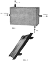
FIG. 1 schematically shows a reactor for thermally decomposing ammonia according to the present invention from the outside; -
FIG. 2 schematically shows a metal plate for use in the reactor ofFIG. 1 ; andFIG. 3 schematically shows the reactor ofFIG. 1 with the housing removed. - The particulars shown herein are by way of example and for purposes of illustrative discussion of the embodiments of the present invention only and are presented in the cause of providing what is believed to be the most useful and readily understood description of the principles and conceptual aspects of the present invention. In this regard, no attempt is made to show structural details of the present invention in more detail than is necessary for the fundamental understanding of the present invention, the description taken with the drawings making apparent to those skilled in the art how the several forms of the present invention may be embodied in practice.
- As used herein, the singular forms "a," "an," and "the" include the plural reference unless the context clearly dictates otherwise. For example, reference to "a ceramic material" would also mean that mixtures of two or more ceramic materials can be present unless specifically excluded.
- Except where otherwise indicated, all numbers expressing quantities of ingredients, reaction conditions, etc. used in the instant specification and appended claims are to be understood as being modified in all instances by the term "about." Accordingly, unless indicated to the contrary, the numerical parameters set forth in the present specification and the appended claims are approximations that may vary depending upon the desired properties sought to be obtained by the present invention. At the very least, each numerical parameter should be construed in light of the number of significant digits and ordinary rounding conventions.
- Additionally, the disclosure of numerical ranges within this specification is considered to be a disclosure of all numerical values and ranges within that range. For example, if a range is from 1 to 50, it is deemed to include, for example, 1, 7, 34, 46.1, 23.7, or any other value or range within the range.
- The process of the present invention comprises contacting ammonia at a temperature of at least 500° C (e.g., at least 525° C, at least 550° C, or at least 575° C, but preferably not higher than 650° C, e.g., not higher than 625° C, or not higher than 600° C) with a porous ceramic layer that comprises nickel. The porous ceramic layer will be present in the form of a (thin) coating on the surface of a metal structure such as a metal plate, a metal sheet or a metal mesh (in the case of a mesh the individual wires of the mesh will be coated). A ceramic layer may be present on one or both major surfaces of the structure, but usually only on one surface thereof.
- A suitable metal (the term "metal" as used herein includes metal alloys) preferably is a metal that is relatively inexpensive while being able to withstand the high temperatures used in the process of the invention under corrosive conditions. The metal may, for example, be an alloy such as steel or stainless steel. The thickness of the metal structure can vary within a wide range, but will often be from 1 mm to 10 mm, e.g., from 2 mm to 7 mm. Merely by way of example, the major dimensions of a metal structure that is present as an approximately rectangular sheet, plate or mesh may, for example be about 40 cm x 20 cm, but may also be considerably larger (e.g., by a factor of 4 or more) or considerably smaller. Of course, the metal structure is not limited to a rectangular shape but can have any shape that is suitable for the intended purpose (e.g., triangular, circular, oval, trapezoid, etc.).
- The porous ceramic layer which is present in the form of a coating on a metal structure will have a thickness of at least 0.1 mm, e.g., at least 0.2 mm, or at least 0.3 mm, but not higher than 1 mm, e.g., not higher than 0.7 mm, or not higher than 0.5 mm.
- The porous ceramic layer may comprise one or more of alumina, zirconia, titanium dioxide, magnesium oxide, calcium oxide, silica, tungsten carbide, silicon nitride or combinations of two or more thereof. In a preferred embodiment the ceramic layer comprises alumina, optionally in combination with other ceramic materials such as, e.g., calcium aluminate.
- The porous ceramic layer will be formed on a substrate metal surface by thermal spraying of a powder of a ceramic material that includes a nickel compound such as nickel oxide. Nickel-based catalysts for the thermal decomposition of ammonia are commercially available, admixed with ceramic material, but usually only in bead or pellet form and the like. If such a commercially available catalyst is to be used, the powder can be produced from the commercial product by comminuting (e.g. grinding) it.
- Additionally, nickel may be incorporated in the porous ceramic layer after the layer has been formed, as discussed in more detail below. The thermal spraying can be carried out by any suitable method such as, e.g., flame spraying, air plasma spraying, high velocity spraying, detonation spraying, warm spraying, cold spraying, corona brushing, protective gas plasma spraying, or vacuum plasma spraying. In order to create pores in the ceramic layer or coating a mixture comprising a ceramic material and a combustible pore forming substance will usually be employed as powder to be subjected to thermal spraying. Suitable combustible pore forming substances include, for example, graphite, vegetable materials, and organic polymers such as, e.g., polyamides. Upon combusting and thereby forming gaseous substances, the combustible materials leave behind voids (pores) in the ceramic layer.
- The surface area of a porous ceramic layer can be further increased by depositing a high surface area ceramic material, such as, e.g., alumina, silica, titanium dioxide, zirconia, aluminum-titanium, silicon carbide and mixtures thereof, in the pores of the ceramic layer by an in-situ precipitation technique, or a sol-gel technique or by injecting the high surface area ceramic material into the jet spray of the ceramic material during the thermal spraying process so that both high surface area ceramic and ceramic material are deposited onto the substrate.
- Additional nickel can be incorporated into a corresponding porous layer by contacting (e.g., impregnating) the layer with an (aqueous) solution of a nickel compound such as nickel chloride or nickel sulfate (e.g., by immersion into a corresponding solution) and thereafter precipitating nickel hydroxide by adding a base to the solution, followed by drying and heating the thus impregnated layer in a reducing or oxidizing atmosphere. For a more detailed discussion of corresponding techniques
U.S. Patent No. 5,980,843 may be referred to. - One of ordinary skill in the art will be aware that in order to be able to effectively catalyze the thermal decomposition of ammonia the catalyst of the present invention has to be reduced at least partially. Ammonia and/or hydrogen gas may, for example, be used for this purpose. If the catalyst is initially used in only partially reduced form it will be reduced completely by the ammonia with which it is contacted at elevated temperature and also by the hydrogen gas that is generated due to the decomposition of ammonia.
- The porous ceramic layer may comprise one or more additional materials which are able to catalyze the thermal decomposition of ammonia, but will usually be substantially free of corresponding materials. In particular, the layer will usually contain not more than trace amounts, if any, of noble metals and other expensive (transition) metals such as Rh, Ir, Pd, Pt, etc. If any other transition metals are present at all, their total concentration will usually be lower than the concentration of nickel by a factor of at least 2, e.g., by a factor of at least 3, at least 5, or at least 10. The concentration of nickel in the porous ceramic layer will be at least 10 % by weight, e.g. at least 15 % by weight, at least 20 % by weight, or at least 25 % by weight, but usually not higher than 45 % by weight, e.g., not higher than 40 % by weight, or not higher than 35 % by weight, in each case calculated as nickel oxide and relative to the total weight of the ceramic layer.
- The process for the thermal decomposition of ammonia into hydrogen and nitrogen according to the present invention comprises contacting heated gaseous ammonia with a nickel containing porous ceramic material (usually at atmospheric pressure, although lower and higher pressures may also be employed). This process can advantageously be carried out at relatively low temperature, even if the degree of ammonia decomposition needs to be high (e.g., at least 99.8 % by volume of ammonia decomposed). The produced mixture of hydrogen and nitrogen may usually be employed without any further purification in a hydrogen-based fuel cell (e.g., an alkaline fuel cell).
- The reactor for the thermal decomposition of ammonia according to the present invention comprises at least one metal structure such as a plate, sheet or mesh which carries a porous ceramic layer that comprises nickel, as described above. The number of metal structures (usually arranged in parallel) comprised in the reactor depends on factors such as, e.g., the desired ammonia decomposition capacity, the dimensions of an individual metal structure, the nickel loading and the porosity and thickness of the ceramic layer. In many cases, the number of metal structures will be at least 5, e.g., at least 10, at least 15 or at least 20, but usually not higher than 100, e.g., not higher than 80, not higher than 60, or not higher than 40.
- The reactor will usually further comprise at least one heating element for heating the ammonia that is introduced into the reactor. For example, the at least one heating element may comprise a catalyst for combusting a fuel. The fuel may, for example, be a gaseous hydrocarbon such as methane, ethane, propane, butane and mixtures thereof and/or may be hydrogen (e.g., a part of the hydrogen that has been generated by the decomposition of ammonia inside the reactor). The catalyst may comprise a transition metal and/or the at least one heating element may comprise a metal plate and/or a metal sheet and/or a metal mesh that is coated with the catalyst. The dimensions of a metal structure that is used for heating may be the same or similar to the dimensions of the metal structure that is used for catalyzing the decomposition of ammonia. The number of heating elements inside the reactor will often be the same or similar to the number of metal structures which carry the porous ceramic coating.
- One of the advantages of the present reactor is that the pressure drop inside the reactor is minimal since the ammonia is passed over a catalyst instead of being passed through a catalyst. The reactor of the present invention is capable of providing a mixture of hydrogen and nitrogen (in a molar ratio of 3: 1), which mixture contains only very small amounts of ammonia (e.g., not more than 0.2 % by volume) and is thus suitable for providing hydrogen to any apparatus that uses hydrogen (diluted with nitrogen) as fuel, such as a hydrogen-based fuel cell (e.g., an alkaline fuel cell). A corresponding fuel cell may, for example, be used as replacement for a conventional source of electrical energy such as a fuel-based generator or may provide energy for a car. In other words, a process for the generation of electricity that comprises using a hydrogen-based fuel cell such as an alkaline fuel cell that is connected to a reactor which contains a Ni-based catalyst of the present invention as set forth above is also described.
- The process and reactor of the present invention will in the following be described by means of non-limiting embodiments thereof.
FIG. 1 schematically shows a cracking reactor according to the present invention. The reactor is constructed from a number of pressed plates (e.g., 20 to 80 plates) such as the one shown inFIG. 2 , which plates are stacked into a heat exchanger reactor. Each plate (dimension about 350 x 200 x 4 mm) is coated with a catalyst, combustion catalyst or cracking catalyst, respectively. In addition, the plates are designed so that additional wire-mesh catalyst for ammonia cracking can be installed between the plates. The plate package is open from the combustion side and the whole package (e.g., 40 plates in total) is inserted into a housing with appropriate connections.FIG. 3 shows the stack of plates without housing. In addition, one plate has been removed to show the additional wire-mesh catalysts which may be sandwiched between the plates. Pre -heated ammonia and air/fuel are supplied to the reactor inlets. Hydrogen is combusted on the combustion catalyst and supplies the endothermic cracking reaction with sufficient heat. The flow pattern in the reactor is counter current to facilitate a high outlet temperature of the product gas, resulting in high reaction rates and low equilibrium concentrations of ammonia. - The reactor features a close coupling between heat transfer and reaction kinetics in a compact structure. The temperature gradients in the catalyst can be reduced to a minimum in this reactor, which means that the utilization of the catalyst can be optimized.
- The ammonia to be introduced in the cracking reactor may be preheated in a heat exchanger by the heat from the hot product gases (hydrogen, nitrogen) leaving the reactor. This heat exchange at the same time cools the product gases to make their temperature suitable for being introduced into an alkaline fuel cell. The tail gas leaving the fuel cell may in turn be used to heat the cracking reactor by combustion (with possible addition of some product gas from the reactor). The air/tail gas mixture may be recuperated with the combustion gases leaving the heat-exchanger reactor.
- It is noted that the foregoing examples have been provided merely for the purpose of explanation and are in no way to be construed as limiting of the present invention. While the present invention has been described with reference to exemplary embodiments, it is understood that the words which have been used herein are words of description and illustration, rather than words of limitation. Changes may be made, within the purview of the appended claims, as presently stated and as amended, without departing from the scope and spirit of the present invention in its aspects. Although the present invention has been described herein with reference to particular means, materials and embodiments, the present invention is not intended to be limited to the particulars disclosed herein; rather, the present invention extends to all functionally equivalent structures, methods and uses, such as are within the scope of the appended claims.
Claims (15)
- A process for the catalytic thermal decomposition of ammonia into hydrogen and nitrogen, wherein the process comprises forming a porous ceramic layer which comprises nickel as a catalyst for the thermal decomposition of ammonia by thermal spraying of a powder of a ceramic material which includes a nickel compound on a metal surface and contacting ammonia at a temperature of at least 500° C with the porous ceramic layer which comprises at least 10 % by weight of nickel, calculated as nickel oxide and has a thickness of from 0.1 mm to 1 mm.
- The process of claim 1, wherein the porous ceramic layer is present on the metal surface, which is a metal alloy surface.
- The process of claim 2, wherein the metal surface is a steel surface.
- The process of any one of claims 2 and 3, wherein the layer is present on a metal sheet or a metal plate.
- The process of any one of claims 2 to 4, wherein the layer has a thickness of from 0.2 mm to 0.7 mm.
- The process of any one of claims 1 to 5, wherein the porous ceramic layer comprises one or more of alumina, zirconia, titanium dioxide, magnesium oxide, calcium oxide, silica, tungsten carbide, silicon nitride.
- The process of any one of claims 1 to 6, wherein the porous ceramic layer comprises alumina and calcium aluminate.
- The process of any one of claims 1 to 7, wherein the nickel compound is or comprises nickel oxide.
- The process of any one of claims 1 to 8, wherein the porous ceramic layer has been formed starting from a mixture comprising the ceramic material and a combustible pore forming substance.
- The process of claim 9, wherein the combustible pore forming substance is selected from one or more of graphite, vegetable materials, organic polymers.
- The process of any one of claims 1 to 10, wherein the porous ceramic material is substantially free of Rh, Ir, Ru, Pd, Pt.
- The process of any one of claims 1 to 11, wherein the porous ceramic material comprises at least 15 % by weight of nickel, calculated as nickel oxide.
- The process of any one of claims 1 to 12, wherein the catalyst is present in at least partially reduced form.
- The process of claim 13, wherein the catalyst has been reduced with ammonia and/or hydrogen.
- A reactor for the thermal decomposition of ammonia according to any one of claims 1 to 14, wherein the reactor comprises at least one metal structure which carries a porous ceramic layer which comprises at least 10 % by weight of nickel, calculated as nickel oxide, as a catalyst for the thermal decomposition of ammonia and has been formed by thermal spraying of a powder of a ceramic material which includes a nickel compound onto the metal structure and has a thickness of from 0.1 mm to 1 mm.
Applications Claiming Priority (2)
| Application Number | Priority Date | Filing Date | Title |
|---|---|---|---|
| US201562195516P | 2015-07-22 | 2015-07-22 | |
| PCT/US2016/043581 WO2017015569A1 (en) | 2015-07-22 | 2016-07-22 | Process for the thermal decomposition of ammonia and reactor for carrying out said process |
Publications (4)
| Publication Number | Publication Date |
|---|---|
| EP3325406A1 EP3325406A1 (en) | 2018-05-30 |
| EP3325406A4 EP3325406A4 (en) | 2019-01-23 |
| EP3325406B1 true EP3325406B1 (en) | 2025-06-11 |
| EP3325406C0 EP3325406C0 (en) | 2025-06-11 |
Family
ID=57834699
Family Applications (1)
| Application Number | Title | Priority Date | Filing Date |
|---|---|---|---|
| EP16828614.4A Active EP3325406B1 (en) | 2015-07-22 | 2016-07-22 | Process for the thermal decomposition of ammonia and reactor for carrying out said process |
Country Status (4)
| Country | Link |
|---|---|
| US (1) | US10450192B2 (en) |
| EP (1) | EP3325406B1 (en) |
| IL (1) | IL257019B2 (en) |
| WO (1) | WO2017015569A1 (en) |
Families Citing this family (25)
| Publication number | Priority date | Publication date | Assignee | Title |
|---|---|---|---|---|
| WO2017160154A1 (en) * | 2016-03-14 | 2017-09-21 | Statoil Petroleum As | Ammonia cracking |
| CN110115927B (en) * | 2019-06-17 | 2024-02-09 | 辽宁科技大学 | Ultralow nitrogen emission treatment method and ultralow nitrogen emission treatment system for ammonia-containing waste gas |
| CN110327957A (en) * | 2019-06-20 | 2019-10-15 | 福州大学化肥催化剂国家工程研究中心 | A kind of preparation method of ammonia decomposition catalyzer |
| CN112973679B (en) * | 2019-12-17 | 2022-04-29 | 中国科学院大连化学物理研究所 | Alkaline earth metal oxide supported ruthenium catalyst and preparation method and application |
| US11724245B2 (en) * | 2021-08-13 | 2023-08-15 | Amogy Inc. | Integrated heat exchanger reactors for renewable fuel delivery systems |
| US12000333B2 (en) | 2021-05-14 | 2024-06-04 | AMOGY, Inc. | Systems and methods for processing ammonia |
| EP4352008A4 (en) | 2021-06-11 | 2025-07-02 | Amogy Inc | SYSTEMS AND METHODS FOR PROCESSING AMMONIA |
| US11539063B1 (en) | 2021-08-17 | 2022-12-27 | Amogy Inc. | Systems and methods for processing hydrogen |
| DE102021211436A1 (en) | 2021-10-11 | 2023-04-13 | Siemens Energy Global GmbH & Co. KG | Ammonia crackers in ceramic liners and process |
| CN117258799A (en) * | 2022-06-15 | 2023-12-22 | 香港理工大学 | Ruthenium nickel-aluminum-based catalyst for preparing nitrogen and hydrogen by ammonia catalysis, and preparation method and application thereof |
| US12467422B2 (en) * | 2022-08-06 | 2025-11-11 | First Ammonia Motors, Inc. | Systems and methods for the on-board catalytic production of hydrogen from phase-controlled gaseous ammonia |
| US12358787B2 (en) | 2022-08-06 | 2025-07-15 | First Ammonia Motors, Inc. | Systems and methods for an internal combustion engine utilizing ammonia as a fuel source and as a heat-exchange medium for engine cooling |
| US12371319B2 (en) | 2022-08-06 | 2025-07-29 | First Ammonia Motors, Inc. | Systems and methods for cooling hydrogen fuel generated on-board prior to injection into an internal combustion engine |
| US12435686B2 (en) | 2022-08-06 | 2025-10-07 | First Ammonia Motors, Inc. | Systems and methods for the on-board production of hydrogen from ammonia for fueling an internal combustion engine that requires no fossil fuel promotor |
| US12162754B2 (en) | 2022-11-14 | 2024-12-10 | First Ammonia Motors, Inc. | Systems and methods for engine-mounted catalytic production of hydrogen from ammonia for use as a combustion fuel |
| US11834334B1 (en) | 2022-10-06 | 2023-12-05 | Amogy Inc. | Systems and methods of processing ammonia |
| US11866328B1 (en) | 2022-10-21 | 2024-01-09 | Amogy Inc. | Systems and methods for processing ammonia |
| US11795055B1 (en) | 2022-10-21 | 2023-10-24 | Amogy Inc. | Systems and methods for processing ammonia |
| US20240174516A1 (en) | 2022-11-30 | 2024-05-30 | ExxonMobil Technology and Engineering Company | Reverse flow reactor for ammonia cracking |
| CN116293676B (en) * | 2023-05-18 | 2023-08-01 | 佛山仙湖实验室 | Porous medium combustion device, ammonia gas combustion system and combustion control method |
| US12442324B1 (en) | 2023-09-01 | 2025-10-14 | First Ammonia Motors, Inc. | Systems and methods for supplementing an ammonia heat-exchange unit for engine cooling with a radiator |
| US12617673B2 (en) | 2023-09-01 | 2026-05-05 | First Ammonia Motors, Inc. | Systems and methods for phase-safe ammonia vapor fuel delivery to an internal combustion engine |
| AU2024379050A1 (en) | 2023-11-14 | 2026-04-30 | Afc Energy Plc | Catalytic reactor with combustion chamber |
| WO2025206204A1 (en) * | 2024-03-29 | 2025-10-02 | 国立大学法人 東京大学 | Gaseous-substance pyrolysis apparatus and gaseous-substance pyrolysis apparatus stack |
| CN118904378A (en) * | 2024-07-17 | 2024-11-08 | 中国科学院山西煤炭化学研究所 | Silicon nitride loaded metal nanoparticle composite material and preparation method and application thereof |
Citations (2)
| Publication number | Priority date | Publication date | Assignee | Title |
|---|---|---|---|---|
| EP1436445A1 (en) * | 2001-08-30 | 2004-07-14 | Atkina Limited | Process for making thin film porous ceramic-metal composites and composites obtained by this process |
| WO2007012890A1 (en) * | 2005-07-26 | 2007-02-01 | Compactgtl Plc | Catalyst |
Family Cites Families (18)
| Publication number | Priority date | Publication date | Assignee | Title |
|---|---|---|---|---|
| US4467050A (en) * | 1982-07-08 | 1984-08-21 | Energy Research Corporation | Fuel cell catalyst member and method of making same |
| JPH01119341A (en) | 1987-10-30 | 1989-05-11 | Nkk Corp | Catalyst for ammonia decomposition |
| JP2841411B2 (en) | 1989-01-27 | 1998-12-24 | 日本鋼管株式会社 | How to get hydrogen from ammonia |
| US5451386A (en) * | 1993-05-19 | 1995-09-19 | The State Of Oregon Acting By And Through The State Board Of Higher Education On Behalf Of Osu | Hydrogen-selective membrane |
| SE504795C2 (en) | 1995-07-05 | 1997-04-28 | Katator Ab | Network-based combustion catalyst and production thereof |
| US5976723A (en) | 1997-03-12 | 1999-11-02 | Boffito; Claudio | Getter materials for cracking ammonia |
| WO2001087770A1 (en) * | 2000-05-12 | 2001-11-22 | Gradient Technology | Production of hydrogen by autothermic decomposition of ammonia |
| AU2001281329A1 (en) | 2000-07-25 | 2002-02-05 | Apollo Energy Systems, Incorporated | Ammonia cracker for production of hydrogen |
| US7867300B2 (en) * | 2001-03-02 | 2011-01-11 | Intelligent Energy, Inc. | Ammonia-based hydrogen generation apparatus and method for using same |
| EP1372839A4 (en) | 2001-03-02 | 2006-11-29 | Mesofuel Inc | Ammonia-based hydrogen generation apparatus and method for using same |
| JP4705752B2 (en) * | 2002-12-04 | 2011-06-22 | メタウォーター株式会社 | Energy recovery from ammonia from waste treatment |
| CN1318134C (en) * | 2004-11-11 | 2007-05-30 | 中国科学院大连化学物理研究所 | Prepn of nickel-base catalyst for decomposing ammonia |
| EP1872852A1 (en) | 2005-03-30 | 2008-01-02 | Sued-Chemie Catalysts Japan, Inc. | Ammonia decomposition catalyst and process for decomposition of ammonia using the catalyst |
| GB0621386D0 (en) | 2006-10-27 | 2006-12-06 | Univ Loughborough | Nickel substrates |
| US20080145554A1 (en) | 2006-12-14 | 2008-06-19 | General Electric | Thermal spray powders for wear-resistant coatings, and related methods |
| JP5365037B2 (en) | 2008-03-18 | 2013-12-11 | トヨタ自動車株式会社 | Hydrogen generator, ammonia burning internal combustion engine, and fuel cell |
| KR101595963B1 (en) * | 2008-09-17 | 2016-02-19 | 가부시기가이샤 닛뽕쇼꾸바이 | Catalyst for ammonia decomposition, process for producing same, and method of treating ammonia |
| MX2017009789A (en) | 2015-02-03 | 2017-12-04 | Gencell Ltd | NICKEL BASED CATALYST FOR THE DECOMPOSITION OF AMMONIA. |
-
2016
- 2016-07-22 WO PCT/US2016/043581 patent/WO2017015569A1/en not_active Ceased
- 2016-07-22 US US15/746,085 patent/US10450192B2/en active Active
- 2016-07-22 EP EP16828614.4A patent/EP3325406B1/en active Active
- 2016-07-22 IL IL257019A patent/IL257019B2/en unknown
Patent Citations (2)
| Publication number | Priority date | Publication date | Assignee | Title |
|---|---|---|---|---|
| EP1436445A1 (en) * | 2001-08-30 | 2004-07-14 | Atkina Limited | Process for making thin film porous ceramic-metal composites and composites obtained by this process |
| WO2007012890A1 (en) * | 2005-07-26 | 2007-02-01 | Compactgtl Plc | Catalyst |
Also Published As
| Publication number | Publication date |
|---|---|
| WO2017015569A1 (en) | 2017-01-26 |
| IL257019B1 (en) | 2023-06-01 |
| EP3325406A1 (en) | 2018-05-30 |
| IL257019B2 (en) | 2023-10-01 |
| US20180230006A1 (en) | 2018-08-16 |
| IL257019A (en) | 2018-03-29 |
| EP3325406C0 (en) | 2025-06-11 |
| US10450192B2 (en) | 2019-10-22 |
| EP3325406A4 (en) | 2019-01-23 |
Similar Documents
| Publication | Publication Date | Title |
|---|---|---|
| US10450192B2 (en) | Process for the thermal decomposition of ammonia and reactor for carrying out said process | |
| Spatolisano et al. | Ammonia as a carbon-free energy carrier: NH3 cracking to H2 | |
| US11253831B2 (en) | Catalytically heated fuel processor with replaceable structured supports bearing catalyst for fuel cell | |
| KR102428962B1 (en) | Lightweight hydrogen generating reactor comprising composite materials with high efficiency | |
| JP5457395B2 (en) | Hydrogen generator and hydrogen generation method | |
| US6576203B2 (en) | Reformer | |
| US20050069485A1 (en) | Compact partial oxidation reactor assemblage with fast start-up capability | |
| JP2004525058A (en) | Ammonia-based hydrogen generator and method of using the same | |
| WO2021221943A1 (en) | Process for the thermal decomposition of ammonia and reactor for carrying out the process | |
| KR20210059656A (en) | Hydrogen Production Reactor without Carbon Emission | |
| Idamakanti et al. | Electrified catalysts for endothermic chemical processes: materials needs, advances, and challenges | |
| EP3253487A1 (en) | Nickel-based catalyst for the decomposition of ammonia | |
| Sadykov et al. | Transformation of CH4 and liquid fuels into syngas on monolithic catalysts | |
| JP2000007304A (en) | Reforming reactor | |
| JPS5826002A (en) | Steam reforming method and reaction tube for steam reforming | |
| US7740670B2 (en) | Catalyst for partial oxidation reforming of fuel and fuel reforming apparatus and method using the catalyst | |
| KR101751589B1 (en) | Heat Exchanger-Type Reactor Having Plates Coated with Different Catalysts | |
| JP2004231468A (en) | Hydrogen gas generator | |
| JP2000007303A (en) | Reforming reactor | |
| JP2000007302A (en) | Reforming reactor | |
| WO2025206204A1 (en) | Gaseous-substance pyrolysis apparatus and gaseous-substance pyrolysis apparatus stack | |
| JP2000126595A (en) | Catalyst for reforming hydrocarbon | |
| AU2021344092A1 (en) | Hydrocarbon production method |
Legal Events
| Date | Code | Title | Description |
|---|---|---|---|
| STAA | Information on the status of an ep patent application or granted ep patent |
Free format text: STATUS: THE INTERNATIONAL PUBLICATION HAS BEEN MADE |
|
| PUAI | Public reference made under article 153(3) epc to a published international application that has entered the european phase |
Free format text: ORIGINAL CODE: 0009012 |
|
| STAA | Information on the status of an ep patent application or granted ep patent |
Free format text: STATUS: REQUEST FOR EXAMINATION WAS MADE |
|
| 17P | Request for examination filed |
Effective date: 20180206 |
|
| AK | Designated contracting states |
Kind code of ref document: A1 Designated state(s): AL AT BE BG CH CY CZ DE DK EE ES FI FR GB GR HR HU IE IS IT LI LT LU LV MC MK MT NL NO PL PT RO RS SE SI SK SM TR |
|
| AX | Request for extension of the european patent |
Extension state: BA ME |
|
| DAV | Request for validation of the european patent (deleted) | ||
| DAX | Request for extension of the european patent (deleted) | ||
| A4 | Supplementary search report drawn up and despatched |
Effective date: 20190104 |
|
| RIC1 | Information provided on ipc code assigned before grant |
Ipc: B01J 19/00 20060101ALI20181220BHEP Ipc: H01M 8/0606 20160101ALI20181220BHEP Ipc: C01B 3/04 20060101AFI20181220BHEP Ipc: B01J 8/00 20060101ALI20181220BHEP Ipc: B01J 8/18 20060101ALI20181220BHEP |
|
| STAA | Information on the status of an ep patent application or granted ep patent |
Free format text: STATUS: EXAMINATION IS IN PROGRESS |
|
| 17Q | First examination report despatched |
Effective date: 20211011 |
|
| 17Q | First examination report despatched |
Effective date: 20211022 |
|
| GRAP | Despatch of communication of intention to grant a patent |
Free format text: ORIGINAL CODE: EPIDOSNIGR1 |
|
| STAA | Information on the status of an ep patent application or granted ep patent |
Free format text: STATUS: GRANT OF PATENT IS INTENDED |
|
| INTG | Intention to grant announced |
Effective date: 20250102 |
|
| GRAS | Grant fee paid |
Free format text: ORIGINAL CODE: EPIDOSNIGR3 |
|
| GRAA | (expected) grant |
Free format text: ORIGINAL CODE: 0009210 |
|
| STAA | Information on the status of an ep patent application or granted ep patent |
Free format text: STATUS: THE PATENT HAS BEEN GRANTED |
|
| AK | Designated contracting states |
Kind code of ref document: B1 Designated state(s): AL AT BE BG CH CY CZ DE DK EE ES FI FR GB GR HR HU IE IS IT LI LT LU LV MC MK MT NL NO PL PT RO RS SE SI SK SM TR |
|
| REG | Reference to a national code |
Ref country code: GB Ref legal event code: FG4D |
|
| REG | Reference to a national code |
Ref country code: CH Ref legal event code: EP |
|
| REG | Reference to a national code |
Ref country code: DE Ref legal event code: R096 Ref document number: 602016092547 Country of ref document: DE |
|
| REG | Reference to a national code |
Ref country code: IE Ref legal event code: FG4D |
|
| U01 | Request for unitary effect filed |
Effective date: 20250710 |
|
| U07 | Unitary effect registered |
Designated state(s): AT BE BG DE DK EE FI FR IT LT LU LV MT NL PT RO SE SI Effective date: 20250716 |
|
| U20 | Renewal fee for the european patent with unitary effect paid |
Year of fee payment: 10 Effective date: 20250731 |
|
| PG25 | Lapsed in a contracting state [announced via postgrant information from national office to epo] |
Ref country code: ES Free format text: LAPSE BECAUSE OF FAILURE TO SUBMIT A TRANSLATION OF THE DESCRIPTION OR TO PAY THE FEE WITHIN THE PRESCRIBED TIME-LIMIT Effective date: 20250611 |
|
| PG25 | Lapsed in a contracting state [announced via postgrant information from national office to epo] |
Ref country code: GR Free format text: LAPSE BECAUSE OF FAILURE TO SUBMIT A TRANSLATION OF THE DESCRIPTION OR TO PAY THE FEE WITHIN THE PRESCRIBED TIME-LIMIT Effective date: 20250912 Ref country code: NO Free format text: LAPSE BECAUSE OF FAILURE TO SUBMIT A TRANSLATION OF THE DESCRIPTION OR TO PAY THE FEE WITHIN THE PRESCRIBED TIME-LIMIT Effective date: 20250911 |
|
| PG25 | Lapsed in a contracting state [announced via postgrant information from national office to epo] |
Ref country code: HR Free format text: LAPSE BECAUSE OF FAILURE TO SUBMIT A TRANSLATION OF THE DESCRIPTION OR TO PAY THE FEE WITHIN THE PRESCRIBED TIME-LIMIT Effective date: 20250611 |
|
| PG25 | Lapsed in a contracting state [announced via postgrant information from national office to epo] |
Ref country code: RS Free format text: LAPSE BECAUSE OF FAILURE TO SUBMIT A TRANSLATION OF THE DESCRIPTION OR TO PAY THE FEE WITHIN THE PRESCRIBED TIME-LIMIT Effective date: 20250911 |
|
| PG25 | Lapsed in a contracting state [announced via postgrant information from national office to epo] |
Ref country code: IS Free format text: LAPSE BECAUSE OF FAILURE TO SUBMIT A TRANSLATION OF THE DESCRIPTION OR TO PAY THE FEE WITHIN THE PRESCRIBED TIME-LIMIT Effective date: 20251011 |
|
| PG25 | Lapsed in a contracting state [announced via postgrant information from national office to epo] |
Ref country code: SM Free format text: LAPSE BECAUSE OF FAILURE TO SUBMIT A TRANSLATION OF THE DESCRIPTION OR TO PAY THE FEE WITHIN THE PRESCRIBED TIME-LIMIT Effective date: 20250611 |
|
| PG25 | Lapsed in a contracting state [announced via postgrant information from national office to epo] |
Ref country code: CZ Free format text: LAPSE BECAUSE OF FAILURE TO SUBMIT A TRANSLATION OF THE DESCRIPTION OR TO PAY THE FEE WITHIN THE PRESCRIBED TIME-LIMIT Effective date: 20250611 |
|
| PG25 | Lapsed in a contracting state [announced via postgrant information from national office to epo] |
Ref country code: PL Free format text: LAPSE BECAUSE OF FAILURE TO SUBMIT A TRANSLATION OF THE DESCRIPTION OR TO PAY THE FEE WITHIN THE PRESCRIBED TIME-LIMIT Effective date: 20250611 |
|
| PG25 | Lapsed in a contracting state [announced via postgrant information from national office to epo] |
Ref country code: SK Free format text: LAPSE BECAUSE OF FAILURE TO SUBMIT A TRANSLATION OF THE DESCRIPTION OR TO PAY THE FEE WITHIN THE PRESCRIBED TIME-LIMIT Effective date: 20250611 |
|
| REG | Reference to a national code |
Ref country code: CH Ref legal event code: H13 Free format text: ST27 STATUS EVENT CODE: U-0-0-H10-H13 (AS PROVIDED BY THE NATIONAL OFFICE) Effective date: 20260224 |
|
| PG25 | Lapsed in a contracting state [announced via postgrant information from national office to epo] |
Ref country code: MC Free format text: LAPSE BECAUSE OF FAILURE TO SUBMIT A TRANSLATION OF THE DESCRIPTION OR TO PAY THE FEE WITHIN THE PRESCRIBED TIME-LIMIT Effective date: 20250611 |
|
| PLBE | No opposition filed within time limit |
Free format text: ORIGINAL CODE: 0009261 |
|
| STAA | Information on the status of an ep patent application or granted ep patent |
Free format text: STATUS: NO OPPOSITION FILED WITHIN TIME LIMIT |
|
| PG25 | Lapsed in a contracting state [announced via postgrant information from national office to epo] |
Ref country code: CH Free format text: LAPSE BECAUSE OF NON-PAYMENT OF DUE FEES Effective date: 20250731 |
|
| REG | Reference to a national code |
Ref country code: CH Ref legal event code: L10 Free format text: ST27 STATUS EVENT CODE: U-0-0-L10-L00 (AS PROVIDED BY THE NATIONAL OFFICE) Effective date: 20260423 |