EP3324801B1 - Appliance for foaming beverage or foodstuff - Google Patents
Appliance for foaming beverage or foodstuff Download PDFInfo
- Publication number
- EP3324801B1 EP3324801B1 EP16736203.7A EP16736203A EP3324801B1 EP 3324801 B1 EP3324801 B1 EP 3324801B1 EP 16736203 A EP16736203 A EP 16736203A EP 3324801 B1 EP3324801 B1 EP 3324801B1
- Authority
- EP
- European Patent Office
- Prior art keywords
- phase
- container
- stator
- electrically conductive
- portions
- Prior art date
- Legal status (The legal status is an assumption and is not a legal conclusion. Google has not performed a legal analysis and makes no representation as to the accuracy of the status listed.)
- Active
Links
Images



Classifications
-
- A—HUMAN NECESSITIES
- A47—FURNITURE; DOMESTIC ARTICLES OR APPLIANCES; COFFEE MILLS; SPICE MILLS; SUCTION CLEANERS IN GENERAL
- A47J—KITCHEN EQUIPMENT; COFFEE MILLS; SPICE MILLS; APPARATUS FOR MAKING BEVERAGES
- A47J43/00—Implements for preparing or holding food, not provided for in other groups of this subclass
- A47J43/04—Machines for domestic use not covered elsewhere, e.g. for grinding, mixing, stirring, kneading, emulsifying, whipping or beating foodstuffs, e.g. power-driven
- A47J43/07—Parts or details, e.g. mixing tools, whipping tools
- A47J43/08—Driving mechanisms
- A47J43/085—Driving mechanisms for machines with tools driven from the lower side
-
- A—HUMAN NECESSITIES
- A47—FURNITURE; DOMESTIC ARTICLES OR APPLIANCES; COFFEE MILLS; SPICE MILLS; SUCTION CLEANERS IN GENERAL
- A47J—KITCHEN EQUIPMENT; COFFEE MILLS; SPICE MILLS; APPARATUS FOR MAKING BEVERAGES
- A47J31/00—Apparatus for making beverages
- A47J31/44—Parts or details or accessories of beverage-making apparatus
- A47J31/4496—Means to produce beverage with a layer on top, e.g. of cream, foam or froth
-
- A—HUMAN NECESSITIES
- A47—FURNITURE; DOMESTIC ARTICLES OR APPLIANCES; COFFEE MILLS; SPICE MILLS; SUCTION CLEANERS IN GENERAL
- A47J—KITCHEN EQUIPMENT; COFFEE MILLS; SPICE MILLS; APPARATUS FOR MAKING BEVERAGES
- A47J43/00—Implements for preparing or holding food, not provided for in other groups of this subclass
- A47J43/04—Machines for domestic use not covered elsewhere, e.g. for grinding, mixing, stirring, kneading, emulsifying, whipping or beating foodstuffs, e.g. power-driven
- A47J43/046—Machines for domestic use not covered elsewhere, e.g. for grinding, mixing, stirring, kneading, emulsifying, whipping or beating foodstuffs, e.g. power-driven with tools driven from the bottom side
- A47J43/0465—Machines for domestic use not covered elsewhere, e.g. for grinding, mixing, stirring, kneading, emulsifying, whipping or beating foodstuffs, e.g. power-driven with tools driven from the bottom side with magnetic drive
-
- B—PERFORMING OPERATIONS; TRANSPORTING
- B01—PHYSICAL OR CHEMICAL PROCESSES OR APPARATUS IN GENERAL
- B01F—MIXING, e.g. DISSOLVING, EMULSIFYING OR DISPERSING
- B01F23/00—Mixing according to the phases to be mixed, e.g. dispersing or emulsifying
- B01F23/20—Mixing gases with liquids
- B01F23/23—Mixing gases with liquids by introducing gases into liquid media, e.g. for producing aerated liquids
- B01F23/235—Mixing gases with liquids by introducing gases into liquid media, e.g. for producing aerated liquids for making foam
- B01F23/2351—Mixing gases with liquids by introducing gases into liquid media, e.g. for producing aerated liquids for making foam using driven stirrers
-
- B—PERFORMING OPERATIONS; TRANSPORTING
- B01—PHYSICAL OR CHEMICAL PROCESSES OR APPARATUS IN GENERAL
- B01F—MIXING, e.g. DISSOLVING, EMULSIFYING OR DISPERSING
- B01F33/00—Other mixers; Mixing plants; Combinations of mixers
- B01F33/45—Magnetic mixers; Mixers with magnetically driven stirrers
- B01F33/453—Magnetic mixers; Mixers with magnetically driven stirrers using supported or suspended stirring elements
- B01F33/4533—Magnetic mixers; Mixers with magnetically driven stirrers using supported or suspended stirring elements supporting the stirring element in one point
-
- B—PERFORMING OPERATIONS; TRANSPORTING
- B01—PHYSICAL OR CHEMICAL PROCESSES OR APPARATUS IN GENERAL
- B01F—MIXING, e.g. DISSOLVING, EMULSIFYING OR DISPERSING
- B01F2101/00—Mixing characterised by the nature of the mixed materials or by the application field
- B01F2101/06—Mixing of food ingredients
-
- B—PERFORMING OPERATIONS; TRANSPORTING
- B01—PHYSICAL OR CHEMICAL PROCESSES OR APPARATUS IN GENERAL
- B01F—MIXING, e.g. DISSOLVING, EMULSIFYING OR DISPERSING
- B01F2101/00—Mixing characterised by the nature of the mixed materials or by the application field
- B01F2101/06—Mixing of food ingredients
- B01F2101/14—Mixing of ingredients for non-alcoholic beverages; Dissolving sugar in water
Definitions
- the present invention relates to an appliance for the foaming of a beverage or foodstuff, the appliance comprising an agitator and a magnetic drive system for driving said agitator.
- foam i.e. to aerate to a froth by the trapping of air pockets
- beverages or foodstuffs, or components thereof during beverage preparation.
- milk that is foamed with coffee added thereto to form a latte or a cappuccino.
- whisking of egg whites or cream to a mousse is desirable to foam (i.e. to aerate to a froth by the trapping of air pockets) beverages or foodstuffs, or components thereof, during beverage preparation.
- milk that is foamed with coffee added thereto to form a latte or a cappuccino.
- whisking of egg whites or cream to a mousse is the whisking of egg whites or cream to a mousse.
- a container for containing a liquid to be foamed has arranged therein a rotary agitator which is rotated for said foaming.
- the rotary agitator is part of an agitation system that further comprises: permanent agitator magnets incorporated on the rotary agitator; permanent drive magnets arranged external the container; a rotor operable to rotate said drive magnets, whereby rotation of the drive magnets effects a rotating magnetic field to transmit torque to the agitator magnets.
- the rotor is driven by an electrically operated motor, which is arranged beneath the container.
- the housing of the appliance has to house said motor and the drive magnets, both of which are bulky and impose size constraints on the housing, which is undesirable for reasons material wastage and economy of space on a worktop.
- said drive magnets are limited in the amount of torque they can apply to the whisk by virtue of their degree of magnetisation.
- Document WO-A-2014/009858 of the prior art discloses an apparatus for agitating liquid foodstuff, comprising a whisk with a magnetic rotor and a main body with a container where the whisk rotates, and a stator.
- the stator includes at least one magnetic sensor to provide a signal that reflects positional changes of a magnetic rotor relative to a magnetic sensor.
- the housing of the appliance needs to house the electrical connector of the motor, which is bulky so imposes size constraints.
- An object of the invention is to provide an appliance with an agitation system which is more compact.
- Objects of the invention are achieved by: the appliance according to claim 1 and the method according to claim 13.
- an appliance e.g. for home use by an end user to foam (e.g. to aerate or froth) a liquid for end user consumption
- the appliance comprising: a container mounting portion to mount thereto (e.g. removably or permanently mounted) a container to contain said liquid; an agitation system configured to foam said liquid, said system comprising a stator arranged external a mounted container (e.g. beneath a base of a mounted container), said stator configured to generate a rotating magnetic field for transmission of torque to rotate a rotary agitator arranged in a mounted container, wherein said stator comprises at a circuit board with electrically conductive portions formed thereon.
- the rotary agitator and stator thus form an electric motor.
- the rotating magnetic field thus extends into a mounted container and rotates therein.
- the object of the invention is achieved since the stator of the appliance is particularly compact in comparison to the prior art, which comprises arranged within the appliance a motor driving permanent magnets. Moreover, a stator formed with electrically conductive portions on a circuit board can be conveniently and precisely formed when compared to a coiled wire arrangement. Furthermore it has enhanced heat dissipation.
- the stator may be generally disc shaped.
- the stator may be arranged generally perpendicular to the axis of rotation of said field.
- the stator preferably extends parallel to a base of a mounted container.
- the circuit board(s) comprise a non-conductive material, such as polyethylene terephthalate (PET) or glass fibre reinforced (fiberglass) epoxy resin.
- the electrically conductive material generally comprises a metal, such as copper.
- the electrically conductive material can be formed on the circuit board(s) by known means, e.g. etching or printing.
- the electrically conductive portions are formed conveniently with a high level of precision.
- the stator may comprise one or a plurality (e.g. and number between 1 and 20, such as 2, 3, 4, 6) of said circuit board, whereby the plurality of said boards are arranged in the form of a stack (e.g. layered in a generally of fully overlapping arrangement), preferably with the centres thereof aligned to the axis of rotation of the field.
- the plurality of circuit boards are fixed together, e.g. bonded, to form a laminate.
- the plurality of boards enables a high current density in the stator and thus a high magnetic field strength for transmission of high torque.
- the stator may comprise a circuit board with electrically conductive portions formed on one or both faces of the circuit board.
- the electrically conductive portions on both faces of a circuit board enables a high current density in the stator and thus a high magnetic field strength for transmission of high torque.
- an electrical insulator e.g. an isolant such as a glass fibre, epoxy resin, is preferably arranged between the circuit boards.
- the electrically conductive portions are connected with a multiphase configuration, e.g. 2, 3, 4, 5, 6 or other suitable number of phases.
- a 3 phase configuration us utilised.
- a phase herein is defined conventionally with respect to electrically operated motors, e.g. each phase comprises an independent arrangement of electrically conductive portions arranged to generate a static magnetic field at a particular position when a current travels therethrough.
- a rotating magnetic field is achieved by sequentially switching the current through the phases, e.g. a phase is switched on by the application of current with a square wave or other suitable waveform.
- the electrically conductive portions of each phase may be arranged to be multipolar, e.g. with 2, 3, 4, 5 or other suitable number of pole pairs.
- having multiple pole pairs enables smooth torque delivery, and in particular a complex arrangement of many poles can be conveniently and precisely formed on the circuit boards using one of the aforesaid methods.
- the said multiphase, multipolar configuration is preferably configured to generate a rotating magnetic field to transmit torque to a corresponding multipolar permanent magnet arrangement of the rotary agitator arranged in the container.
- each phase may be complimentary in shape (e.g. active portions thereof have a substantially similar shape) to each other and may be rotationally offset to each other, e.g. a 3 phase, 8 pole (i.e. 4 pole pairs) configuration, wherein each phase is rotationally offset by 30 degrees.
- each phase can be conveniently formed using the same process (e.g. template) and then rotationally offset during assembly to define the separate phases.
- Each phase is arranged such that a face of the circuit board(s) comprising a phase comprises a single phase only, e.g.: each phase is arranged on one face only and not on any other faces; or each phase is distributed over a plurality of faces with each of said plurality of faces only comprising one phase only.
- a phase can be layered over several faces (e.g. 2, 3, 4, or more) to achieve a high current density in the stator and thus a high magnetic field strength for transmission of high torque.
- the phases may be symmetrically disposed about a central plane, the central plane being arranged centrally in a through-thickness direction of the circuit board(s), e.g.: a 2 phase arrangement wherein there are two boards, phase 1 is arranged on the outer faces thereof and phase 2 is arranged on the inner faces thereof; a 3 phase arrangement wherein there are three boards, phase 1 is arranged on the outer faces thereof, phase 2 is arranged on the inner faces of the outer boards, and phase 3 is arranged on the faces of the central board.
- the magnetic field strength at the rotary agitator is substantially the same for each phase, which result in a more uniform transfer of torque to the rotary agitator together with increased efficiency.
- a face comprises one phase only.
- the electrically conductive portions are preferably arranged into active portions, whereby each active portion is configured to generate a pole for said torque transmission.
- An active portion can be defined as a generating a north pole or a south pole of a pole pair for torque transmission.
- the active portions are circumferentially and equidistantly disposed on a face of a circuit board about the axis of rotation of the magnetic field.
- each active portion comprises one of two predetermined arrangements.
- the electrically conductive portions may comprise vias for connection (e.g. for interconnection of phases disposed over several faces and/or for transmission of current to and from the stator) arranged distal the active portions (i.e. they are not arranged within an active portion).
- the vias can be proximal a periphery of the circuit boards and/or proximal a centre of the circuit boards.
- the vias may be the through extending type.
- the efficiency of the active portions is enhanced since the vias do not interfere with their positioning/arrangement, and thus magnetic field generation.
- the active portions that comprise a phase that are arranged on different faces are preferably configured such that superposed active portions generate a magnetic field vector in the same direction.
- the said direction may alternate between adjacent superposed active portions to define a plurality of poles.
- the different faces comprising a phase each have substantially the same shape of active portion and are rotationally offset by an amount corresponding to (or substantially) an active portion, e.g. a 3 phase, 8 pole (i.e. 4 pole pairs) configuration, wherein each face is rotationally offset by 45 degrees.
- a phase can be conveniently formed using the same template of the active portions, each face is then rotationally offset by an active potion in the board laminate.
- the active portions may be arranged with either a first or second shape.
- Superposed active portions may comprise active portions of the first and second shape. On a face the adjacent active potions may alternate between the first and second shape.
- the active portions may comprise a plurality of tracks.
- An active portion may comprise two generally radially (e.g. exactly radial or radial ⁇ 10 or 5 degrees) extending portions which are interconnected (e.g. by interconnecting portions which may be generally circumferentially arranged). Adjacent active portions preferably share the same radially extending portion.
- the phases may be arranged between faces such that the radially extending portions are generally aligned and overlapping, and which are preferably connected with the current traveling there through in the same direction.
- Advantageously a high current density is achieved.
- the active portions on a face may comprise interconnections of the radial portions alternating between proximal a periphery and a centre of the circuit board, i.e.
- Superposed active portions may comprise radially extending portions that are interconnected on a face proximal a periphery of the board, and complimentary radially extending portions that are interconnected on another face proximal a centre of the board.
- the optionally tracks of the active portions may be 0.25 - 2 mm in thickness (i.e. in the planar direction of the stator).
- the optionally tracks of the active portions may be narrower in thickness and more densely packed along the radially extending portions rather than the interconnecting portions, e.g. they are less than 50% or 75% of the thickness at the interconnection portions.
- the increased width of the interconnecting portions enables improved heat dissipation.
- the stator may extend over a substantial portion of a base of a mounted container, e.g. an overlap of at least 90% or all of the area of the base of a mounted container.
- the magnetic field is generated over a large surface area and can thus induce a large amount of torque in the rotary agitator.
- the stator preferable extends parallel to a base of a mounted container.
- the stator is preferably arranged adjacent a base of the container, e.g. a mounted container sits is at least partially supported by the stator, and sits on the stator with an optional insulating material therebetween.
- the container mounting portion may be configured for permanent or removable attachment of the container, e.g. a bonded, force fit, or screw fit.
- a container which is removable can be removed for cleaning.
- An exterior surface of the stator proximal the container may comprise a protective coating for mounting the container thereon.
- the appliance is compact.
- the appliance comprises a container to contain said liquid for mounting to said mounting portion (e.g. it may be mounted to the mounting portion).
- the appliance comprises a rotary agitator for arrangement in said container (e.g. it may be arranged in said container), wherein the rotary agitator comprises one or more agitator magnets defining magnetic poles for transmission of torque from the magnetic field generated by the stator to the rotary agitator (e.g. the other components of the rotary agitator).
- the container may comprise at a base thereof a location member for location of the rotary agitator.
- the location member is preferably located such that when the container is mounted it is at a centre of rotation of the magnetic field.
- the rotary agitator may comprise an array of magnetic poles circumferentially disposed about an axis of rotation.
- the poles may be formed of discrete magnets, e.g. magnets that comprises single pole pairs, or magnets that comprise a plurality of pole pairs.
- a second aspect of the invention is a method of foaming a liquid for consumption using the appliance according to any feature of the first aspect, said method comprising: generating a rotating magnetic field by applying electrical energy to electrically conductive portions of a stator formed on a circuit board; rotating a rotary agitator arranged in a container for container liquid by applying a torque from said field to the rotary agitator.
- the method may comprise filling the container with liquid to be foamed.
- Generating a rotating magnetic field may comprise sequentially switching the electrical current between the phases of the stator, e.g. by means of a processor.
- An appliance for foaming 2 comprises at a first level thereof: a base unit 4 to transmit torque to a rotary agitator; a container 6 to contain liquid for end user consumption; a rotary agitator 8 to foam said liquid, which are described sequentially as follows.
- the base unit 4 transmits torque to the rotary agitator 8 by means of a magnetic field, and comprises at a first level thereof: a housing 10; container mounting portion 12; agitation system 14; optionally a heater 16; control system 18, which are sequentially described as follows.
- the housing 10 houses and supports said first level components and comprises: a base 22 for abutment of a horizontally arranged support surface; a body 20 for mounting thereto the other first level components.
- the container mounting portion 12 is operable to mount the container 6 to the base unit 4.
- the container mounting portion 12 may be configured for permanent mounting of a container, e.g. it comprises a surface for locating the container to which the container can be bonded.
- the container mounting portion 12 is configured for removable attachment to the container, e.g. it comprises a force fit or screw fit.
- An advantage of a removable attachment is that the container 6 can be detached from the base unit 4 for cleaning.
- the mounting portion 12 may comprise the stator with an optional a protective coating (e.g. an insulating lacquer or a glass fibre epoxy resin) on an outer surface thereof for mounting the container 6 thereon.
- the agitation system 14 is operable to foam liquid in the container 6 by mechanical agitation, in particular by transmission of torque via a magnetic field to a rotary agitator 8, and comprises: a stator 24; a rotary agitator 8; an optional core 30.
- the stator 24 is operable to receive phased electrical energy and to generate therefrom a rotating magnetic field.
- the stator 24 comprises at least one circuit board with electrically conductive portions formed thereon and is discussed in more detail later on.
- the rotary agitator 8 comprises an array of magnetic poles that are circumferentially disposed about an axis of rotation for interaction with the rotating magnetic field generated by the stator 24.
- Agitator magnets 26 of the rotary agitator 8 form said poles and comprise a magnetically hard material capable of a persistent magnetic field.
- the magnets 8 are configured the transmission of torque derived from their interaction with the rotating magnetic field to the remainder of the rotary agitator 8.
- the magnets 26 may comprise discrete units with each comprising a north and south pole. Alternatively one or more of the units may be integrated, e.g. in an annular ring. Other components of the rotary agitator 8 are discussed in more detail later on.
- the optional core 30 is for enhancing the rotating magnetic field and typically comprises a ferromagnetic metal such as iron.
- the code 30 is in general an axially arranged toroid or annular ring positioned proximal a face of the stator 24 that is distal the container 6.
- the optional heater is operable to 16 heat the liquid in the container 6.
- the heater 16 comprises an induction coil operable to heat by electromagnetic induction the rotary agitator 8.
- it may heat the container 6, e.g. the heater comprises a resistive element for heating by conduction.
- the control system 18 is operable to control the agitation system 14 and optional heater, and generally comprises: a user interface 32; optional sensors 34; processor 36; power supply 38, which are described sequentially.
- the user interface 32 comprises hardware to enable an end user to interface with the processor 36 and hence is operatively connected thereto. More particularly: the user interface receives commands from a user; a user interface signal transfers the said commands to the processor 36 as an input.
- the commands may, for example, be an instruction to execute a foaming process and/or a heating process.
- the hardware of the user interface 32 may comprise any suitable device(s), for example, the hardware comprises one or more of the following: buttons, such as a joystick button or press button; joystick; LEDs; graphic or character LDCs; graphical screen with touch sensing and/or screen edge buttons.
- Optional sensors 34 are operatively connected to the processor 36 to provide an input for monitoring said process.
- the sensors 40 typically comprise one or more of the following: liquid temperature sensors; liquid level sensors; position sensors (e.g. hall sensors) for sensing a position of the magnets of the rotary agitator 8 with respect to the stator as will be discussed.
- the processor 36 is generally operable to: receive an input, i.e. the commands from the user interface 32 and/or from the sensors 34; process the input according to program code stored on a memory unit (or programmed logic); provide an output, which is generally the said foaming process and/or a heating process. The process may be executed with open-loop control, or more preferably with closed-loop control using the input signal from the sensors 34 as feedback.
- the processor 36 generally comprises memory, input and output system components, which are arranged as an integrated circuit, typically as a microprocessor or a microcontroller.
- the processor 36 may comprise other suitable integrated circuits, such as: an ASIC; a programmable logic device such as an FPGA; an analogue integrated circuit such as a controller.
- the processor 36 may also comprise one or more of the aforementioned integrated circuits, i.e. multiple processors.
- An example of a suitable component of a processor for stator control is the ESCON 36/3 motor controller by Maxon, which may be controlled by a further processor.
- the processor 36 generally comprises a memory unit for storage of the program code and optionally data.
- the memory unit typically comprises: a non-volatile memory e.g. EPROM, EEPROM or Flash for program code and operating parameter storage; volatile memory (RAM) for data storage.
- RAM volatile memory
- the memory unit may comprise separate and/or integrated (e.g. on a die of the processor) memory.
- the power supply 38 is operable to supply electrical energy to the processor 36, agitation system 14 and heater 16.
- the power supply 38 may comprise various means, such as a battery or a unit to receive and condition a mains electrical supply.
- the container 6, and example of which is illustrated in figure 1 is operable to contain the liquid for foaming.
- the container has a capacity of 0.2 - 0.5 litres.
- the container 6 may be cylindrical (6).
- the container is generally formed of a material that is suitably transparent to a magnetic field, e.g. glass.
- the liquid to be foamed in the container is generally any potable liquid including foodstuffs. Typically it is milk or comprises milk.
- the rotary agitator 8 is operable to rotate to agitate the liquid in the container 6 to effect its foaming.
- the rotary agitator 8 comprises: an axially extending body 40; a support portion 42, radially extending from said body 40 for supporting the agitation portion 28 and the agitator magnets 26.
- the agitation portion 28 may be contoured (as illustrated) or otherwise formed (e.g. comprising holes) to effect fluid agitation upon rotation.
- the body 40 comprises at an end thereof a location member configured to engage with a complimentary location portion of the container 6, e.g. an extension on one of the body 40 or container 6 for insertion into a cavity on the other of the body 40 or container 6.
- the arrangement and pole configuration of the agitator magnets 26 of the rotary agitator 8 is complementary to the poles of the stator 24, e.g. for the later discussed example stator configuration shown in figures 3 and 4 , wherein the stator comprises 8 poles, i.e. 4 pole pairs, there are the same number of poles in the rotary agitator, which are arranged at a complimentary radial distance from the centre of rotation of the magnetic field.
- the stator 24, an idealisation of which is shown in figure 3 , comprises a circuit board 44 and electrically conductive portions 46 arranged thereon.
- the stator 24 may be arranged proximal a base of the container 6 such that it is in operative proximity to the rotary agitator 8, and example of such an arrangement is shown in figure 1 . In particular, it may fully or at least partially overlap (e.g. by covering at least 80% or 90% of the surface area of the base) said base of the container 6.
- the stator 24 is disc shaped with the axis of rotation of the associated magnetic field arranged at a centre thereof, however it will be appreciated that it may comprise other shapes.
- the diameter of the stator (when in disc form) may be 5 cm - 15cm.
- the thickness of an individual circuit board is selected for suitable thermal conduction, e.g. 1 - 2, such as 1.6mm ⁇ 0.15mm.
- the electrically conductive portions 46 and circuit board(s) 44 may have various configurations as will be discussed. They are arranged to effect a multipolar (e.g. 2, 3, 4, 6 or more pole pairs), multiphase (e.g. 2, 3, 4 or more phase) motor configuration, which incorporates a rotor comprising the agitator magnets 26 of the rotary agitator 8. More particularly, the stator and rotor are configured to effect a brushless DC or AC synchronous motor configuration.
- the electrically conductive portions 46 are arranged to define active portions 48 for generation of the magnetic poles. The poles are connected in phases, whereby the individual phases can be switched sequentially to effect rotation of a magnetic field. In particular and active portion is configured to generate one pole (i.e. with a magnetic field vector which is in the north or south direction) of a pole pair.
- stator In a first embodiment stator (not shown) the electrically conductive portions 46 are arranged on one face of a signal circuit board 44. As an example, they are arranged with the active portions thereof extending circumferentially and sequentially in phase order, e.g. a 3 phase configuration, with phase 1, 2, 3 circumferentially extending.
- stator (not shown) the electrically conductive portions 46 are arranged on both faces of a single circuit board 44.
- the aforesaid arrangement for a single face is repeated on both faces of said board 44.
- stator comprises a plurality of said circuit boards, whereby said boards are arranged in the form of a stack, whereby the electrically conductive portions 46 are formed on one or both sides of the associated circuit boards 44.
- adjacent faces of said boards can be electrically isolated by means of an electrically insulating coating such as a glass fibre epoxy resin, e.g. prepreg TU-768 or TU-768P by Taiwan Union Corporation Technology.
- an electrically insulating coating such as a glass fibre epoxy resin, e.g. prepreg TU-768 or TU-768P by Taiwan Union Corporation Technology.
- the stack comprises 3 boards, 44A, 44B, 44C, it will be appreciated that any suitable number of boards can be utilised, e.g. 4 or 6.
- any suitable number of boards can be utilised, e.g. 4 or 6.
- the electrically conductive portions 46 of different faces are interconnected by vias 50 thereof, which are preferably arranged distal said active portions 50 (i.e. a connecting portion of an electrically conduction portion 46 connects a via 50 with an active portion 48). More particularly, the vias 50 can be arranged proximal a periphery of the circuit boards 44 and/or proximal a centre of the circuit boards 44.
- the vias 50 are generally of the through hole type (e.g. extending through one or more circuit boards), however other suitable arrangements are envisaged, e.g. a blind, castellated hole type. An example of such an arrangement is shown in figure 4a , whereby via 50A is proximal a periphery and via 50B is proximal a centre of the board 44.
- the electrically conductive portions 46 are generally complimentary in shape, i.e. each face comprises the same arrangement, but to achieve the different phases the faces are rotationally offset.
- each face comprises the same arrangement, but to achieve the different phases the faces are rotationally offset.
- two circuit boards have arranged on three faces different phases, with each phase having 8 active portions providing 4 pole pairs, and being rotationally offset from the first phase by 30 degrees.
- a phase was arranged on a single face, however in a preferred example of the third embodiment a phase may be distributed over a plurality of faces, e.g. 2, 3 or 4 faces. In this way complementary active portions 48 can be layered to increase current density and field strength.
- FIGS 3a and 3b illustrate such a preferred example, wherein there are three circuit boards 44A, 44B, 44C, with the electrically conductive portions 46 arranged on each face, i.e. utilising all 6 faces (it will be appreciated that 6 circuit boards may alternatively be used with a single face of each utilised) to define 3 phases.
- phase 1 is arranged on the outer faces 52A, 52F of the outer circuit boards 44A, 44C;
- phase 2 is arranged on the inner faces 52B, 52E of the outer circuit boards 44A, 44C;
- phase 3 is arranged on the faces 52C, 52D of the inner circuit board 44B.
- each phase is symmetrically disposed about a central plane, which in this example is centrally though the inner circuit board 44B.
- the said symmetric arrangement can be extended to different numbers of circuit boards 44 and phase arrangements, e.g. a four phase arrangement arranged with a phase over two faces and four circuit boards 44 with both faces used.
- the symmetric arrangement is advantageous since the strength of the magnetic field at the rotary agitator 8 is balanced, which would not be the case if for example a first phase was arranged on the two faces most proximal the rotary agitator, and a third phase was arranged on the two faces most distal the rotary agitator 8.
- the superposed active portions 48 of the same phase when a phase is split over several faces the superposed active portions 48 of the same phase, which are arranged on different faces, are generally complimentary (i.e. they generate a pole with a magnetic field vector of the same direction).
- the other phases can be arranged in the same manner as per the first phase, but rotationally offset therefrom.
- phase 1 the two electrically conductive portion arrangements that comprise phase 1 are shown in figures 4a and 4b , figure 4c shows their supposition;
- phase 2 comprises the same arrangement, but rotated through 30 degrees, the supposition of the two electrically conductive portion arrangements that comprise phase 2 are shown in figure 4d ;
- phase 3 comprises the same arrangement, but rotated through 60 degrees, the supposition of the two electrically conductive portion arrangements that comprise phase 3 are shown in figure 4e .
- figure 4a comprises 8 active portions, whereby the electrical energy (as indicated in the figures by the direction of the current I according to conventional flow notation) is transmitted thereto at via 50A and therefrom at via 50B, accordingly the field vector at the active portion 48 most proximal via 50A is out of the page in the associated region (as indicated), and into the page at the most proximal active portion 48 in the anticlockwise direction and so on as indicated; the active portions 48 of figure 4b are connected to those of figure 4b by means of the vias 50B and 50C hence the current is in a different circumferential direction such that the field vector is in the same direction in the superposed active portions shown in figure 4c .
- the active portions 48 of the associated faces of a phase are rotationally offset by an amount corresponding to an active portion and the active portions between said faces are interconnected such that a current there through is in an opposed direction such that the magnetic field vector generated by superposed active portions is in the same direction.
- an active portion 48 comprises two substantially radially extending portions that are interconnected by interconnecting portions.
- the said radially extending portions are typically 1 - 2 cm in length and 0.5 - 1 cm in width.
- the said radially extending portions comprise a plurality of tracks to control the current flow direction, typically there are 5 - 10 tracks.
- the tracks may vary in width, for example, as illustrated in figure 4 , the tracks are narrower and more densely packed along the radially extending portions.
- the increased width of the interconnecting portions enables improved heat dissipation.
- a radially extending portion is shared between adjacent active portions 48 on the same face.
- the radially extending portions are interconnected alternating between proximal a periphery and a centre of the board, e.g. to form a U shape, whereby the interconnecting side alternates such that two adjacent active portions form an S shape.
- an active portion comprises two sectorialy arranged radially extending portions, which are serially interconnected with neighbouring active portions.
- the radially extending portions generally overlap providing a high current density and thus magnetic field strength, an example of which is illustrated in figure 4c .
- the radially extending portions can be interconnected on one face proximal a periphery of the board, the radially extending portions can be interconnected on another face proximal a centre of the board, an example of which is illustrated in figure 4c .
- the active portions 48 may comprise various other arrangements (not show and including for the first and second embodiment stator), for example, they may be arranged in a substantially rectangular shape, with a via arranged at an interior and outer of said rectangle for connection.
- the processor 36 is configured to control the current applied through the phases.
- the angular frequency of the generated magnetic field may be variable and/or constant, i.e. a phase locked loop, with a reference frequency.
- the position of the rotary agitator 8 can be commutated by position sensors such as an: optical encoder; magnetic encoder (e.g. a resolver, synchro etc.); hall effect sensor, with the latter being preferable due to cost and size.
Landscapes
- Engineering & Computer Science (AREA)
- Food Science & Technology (AREA)
- Mechanical Engineering (AREA)
- Chemical & Material Sciences (AREA)
- Chemical Kinetics & Catalysis (AREA)
- Food-Manufacturing Devices (AREA)
- Mixers With Rotating Receptacles And Mixers With Vibration Mechanisms (AREA)
Description
- The present invention relates to an appliance for the foaming of a beverage or foodstuff, the appliance comprising an agitator and a magnetic drive system for driving said agitator.
- It is desirable to foam (i.e. to aerate to a froth by the trapping of air pockets) beverages or foodstuffs, or components thereof, during beverage preparation. One example is milk that is foamed with coffee added thereto to form a latte or a cappuccino. A further example is the whisking of egg whites or cream to a mousse.
- Accordingly various appliances exist to automate a foaming process. An example of one such appliance is disclosed in
WO 2006/050900 , wherein a container for containing a liquid to be foamed has arranged therein a rotary agitator which is rotated for said foaming. In particular, the rotary agitator is part of an agitation system that further comprises: permanent agitator magnets incorporated on the rotary agitator; permanent drive magnets arranged external the container; a rotor operable to rotate said drive magnets, whereby rotation of the drive magnets effects a rotating magnetic field to transmit torque to the agitator magnets. - In particular the rotor is driven by an electrically operated motor, which is arranged beneath the container. A drawback with such an arrangement is that the housing of the appliance has to house said motor and the drive magnets, both of which are bulky and impose size constraints on the housing, which is undesirable for reasons material wastage and economy of space on a worktop. A further drawback is that said drive magnets are limited in the amount of torque they can apply to the whisk by virtue of their degree of magnetisation.
- Document
WO-A-2014/009858 of the prior art discloses an apparatus for agitating liquid foodstuff, comprising a whisk with a magnetic rotor and a main body with a container where the whisk rotates, and a stator. The stator includes at least one magnetic sensor to provide a signal that reflects positional changes of a magnetic rotor relative to a magnetic sensor. Also in this embodiment, the housing of the appliance needs to house the electrical connector of the motor, which is bulky so imposes size constraints. - An object of the invention is to provide an appliance with an agitation system which is more compact.
- It would be advantageous to provide an agitation that is cost effective to manufacture and/or assemble.
- It would be advantageous to provide an agitation capable of applying high torque to a rotary agitator.
- Objects of the invention are achieved by: the appliance according to claim 1 and the method according to claim 13.
- Disclosed herein according to a first aspect of the invention is an appliance (e.g. for home use by an end user) to foam (e.g. to aerate or froth) a liquid for end user consumption, the appliance comprising: a container mounting portion to mount thereto (e.g. removably or permanently mounted) a container to contain said liquid; an agitation system configured to foam said liquid, said system comprising a stator arranged external a mounted container (e.g. beneath a base of a mounted container), said stator configured to generate a rotating magnetic field for transmission of torque to rotate a rotary agitator arranged in a mounted container, wherein said stator comprises at a circuit board with electrically conductive portions formed thereon. The rotary agitator and stator thus form an electric motor. The rotating magnetic field thus extends into a mounted container and rotates therein.
- Accordingly the object of the invention is achieved since the stator of the appliance is particularly compact in comparison to the prior art, which comprises arranged within the appliance a motor driving permanent magnets. Moreover, a stator formed with electrically conductive portions on a circuit board can be conveniently and precisely formed when compared to a coiled wire arrangement. Furthermore it has enhanced heat dissipation.
- The stator may be generally disc shaped. The stator may be arranged generally perpendicular to the axis of rotation of said field. The stator preferably extends parallel to a base of a mounted container. Advantageously the arrangement is compact. The circuit board(s) comprise a non-conductive material, such as polyethylene terephthalate (PET) or glass fibre reinforced (fiberglass) epoxy resin. The electrically conductive material generally comprises a metal, such as copper. The electrically conductive material can be formed on the circuit board(s) by known means, e.g. etching or printing. Advantageously the electrically conductive portions are formed conveniently with a high level of precision.
- The stator may comprise one or a plurality (e.g. and number between 1 and 20, such as 2, 3, 4, 6) of said circuit board, whereby the plurality of said boards are arranged in the form of a stack (e.g. layered in a generally of fully overlapping arrangement), preferably with the centres thereof aligned to the axis of rotation of the field. The plurality of circuit boards are fixed together, e.g. bonded, to form a laminate. Advantageously the plurality of boards enables a high current density in the stator and thus a high magnetic field strength for transmission of high torque. The stator may comprise a circuit board with electrically conductive portions formed on one or both faces of the circuit board. Advantageously forming the electrically conductive portions on both faces of a circuit board enables a high current density in the stator and thus a high magnetic field strength for transmission of high torque. In the example wherein there is a plurality of circuit boards with adjacent faces thereof comprising electrically conductive portions an electrical insulator, e.g. an isolant such as a glass fibre, epoxy resin, is preferably arranged between the circuit boards.
- The electrically conductive portions are connected with a multiphase configuration, e.g. 2, 3, 4, 5, 6 or other suitable number of phases. Preferably a 3 phase configuration us utilised. A phase herein is defined conventionally with respect to electrically operated motors, e.g. each phase comprises an independent arrangement of electrically conductive portions arranged to generate a static magnetic field at a particular position when a current travels therethrough. A rotating magnetic field is achieved by sequentially switching the current through the phases, e.g. a phase is switched on by the application of current with a square wave or other suitable waveform. The electrically conductive portions of each phase may be arranged to be multipolar, e.g. with 2, 3, 4, 5 or other suitable number of pole pairs. Advantageously, having multiple pole pairs enables smooth torque delivery, and in particular a complex arrangement of many poles can be conveniently and precisely formed on the circuit boards using one of the aforesaid methods. The said multiphase, multipolar configuration is preferably configured to generate a rotating magnetic field to transmit torque to a corresponding multipolar permanent magnet arrangement of the rotary agitator arranged in the container.
- The electrically conductive portions of each phase may be complimentary in shape (e.g. active portions thereof have a substantially similar shape) to each other and may be rotationally offset to each other, e.g. a 3 phase, 8 pole (i.e. 4 pole pairs) configuration, wherein each phase is rotationally offset by 30 degrees. Advantageously each phase can be conveniently formed using the same process (e.g. template) and then rotationally offset during assembly to define the separate phases.
- Each phase is arranged such that a face of the circuit board(s) comprising a phase comprises a single phase only, e.g.: each phase is arranged on one face only and not on any other faces; or each phase is distributed over a plurality of faces with each of said plurality of faces only comprising one phase only. Advantageously a phase can be layered over several faces (e.g. 2, 3, 4, or more) to achieve a high current density in the stator and thus a high magnetic field strength for transmission of high torque.
- With an arrangement with the phases disposed over several faces of the circuit board(s), the phases (e.g. each of the faces of a phase) may be symmetrically disposed about a central plane, the central plane being arranged centrally in a through-thickness direction of the circuit board(s), e.g.: a 2 phase arrangement wherein there are two boards, phase 1 is arranged on the outer faces thereof and
phase 2 is arranged on the inner faces thereof; a 3 phase arrangement wherein there are three boards, phase 1 is arranged on the outer faces thereof,phase 2 is arranged on the inner faces of the outer boards, and phase 3 is arranged on the faces of the central board. - Advantageously, with the aforedescribed symmetric arrangement of the phases the magnetic field strength at the rotary agitator is substantially the same for each phase, which result in a more uniform transfer of torque to the rotary agitator together with increased efficiency. With such an arrangement it is preferable for reasons of complexity that a face comprises one phase only.
- The electrically conductive portions are preferably arranged into active portions, whereby each active portion is configured to generate a pole for said torque transmission. An active portion can be defined as a generating a north pole or a south pole of a pole pair for torque transmission. Generally the active portions are circumferentially and equidistantly disposed on a face of a circuit board about the axis of rotation of the magnetic field. Generally each active portion comprises one of two predetermined arrangements.
- The electrically conductive portions may comprise vias for connection (e.g. for interconnection of phases disposed over several faces and/or for transmission of current to and from the stator) arranged distal the active portions (i.e. they are not arranged within an active portion). In particular the vias can be proximal a periphery of the circuit boards and/or proximal a centre of the circuit boards. Generally the vias may be the through extending type. Advantageously the efficiency of the active portions is enhanced since the vias do not interfere with their positioning/arrangement, and thus magnetic field generation.
- For phases that are distributed over several layers, the active portions that comprise a phase that are arranged on different faces are preferably configured such that superposed active portions generate a magnetic field vector in the same direction. The said direction may alternate between adjacent superposed active portions to define a plurality of poles. In particular, the different faces comprising a phase each have substantially the same shape of active portion and are rotationally offset by an amount corresponding to (or substantially) an active portion, e.g. a 3 phase, 8 pole (i.e. 4 pole pairs) configuration, wherein each face is rotationally offset by 45 degrees. Advantageously, a phase can be conveniently formed using the same template of the active portions, each face is then rotationally offset by an active potion in the board laminate. The active portions may be arranged with either a first or second shape. Superposed active portions may comprise active portions of the first and second shape. On a face the adjacent active potions may alternate between the first and second shape.
- The active portions may comprise a plurality of tracks. An active portion may comprise two generally radially (e.g. exactly radial or radial ± 10 or 5 degrees) extending portions which are interconnected (e.g. by interconnecting portions which may be generally circumferentially arranged). Adjacent active portions preferably share the same radially extending portion. The phases may be arranged between faces such that the radially extending portions are generally aligned and overlapping, and which are preferably connected with the current traveling there through in the same direction. Advantageously a high current density is achieved. The active portions on a face may comprise interconnections of the radial portions alternating between proximal a periphery and a centre of the circuit board, i.e. to form a first and second shape, which is generally a C shape. Superposed active portions may comprise radially extending portions that are interconnected on a face proximal a periphery of the board, and complimentary radially extending portions that are interconnected on another face proximal a centre of the board.
- The optionally tracks of the active portions may be 0.25 - 2 mm in thickness (i.e. in the planar direction of the stator). The optionally tracks of the active portions may be narrower in thickness and more densely packed along the radially extending portions rather than the interconnecting portions, e.g. they are less than 50% or 75% of the thickness at the interconnection portions. Advantageously, the increased width of the interconnecting portions enables improved heat dissipation.
- The stator may extend over a substantial portion of a base of a mounted container, e.g. an overlap of at least 90% or all of the area of the base of a mounted container. Advantageously, the magnetic field is generated over a large surface area and can thus induce a large amount of torque in the rotary agitator. The stator preferable extends parallel to a base of a mounted container. The stator is preferably arranged adjacent a base of the container, e.g. a mounted container sits is at least partially supported by the stator, and sits on the stator with an optional insulating material therebetween.
- The container mounting portion may be configured for permanent or removable attachment of the container, e.g. a bonded, force fit, or screw fit. Advantageously a container which is removable can be removed for cleaning. An exterior surface of the stator proximal the container may comprise a protective coating for mounting the container thereon. Advantageously, the appliance is compact.
- The appliance comprises a container to contain said liquid for mounting to said mounting portion (e.g. it may be mounted to the mounting portion). The appliance comprises a rotary agitator for arrangement in said container (e.g. it may be arranged in said container), wherein the rotary agitator comprises one or more agitator magnets defining magnetic poles for transmission of torque from the magnetic field generated by the stator to the rotary agitator (e.g. the other components of the rotary agitator).
- The container may comprise at a base thereof a location member for location of the rotary agitator. The location member is preferably located such that when the container is mounted it is at a centre of rotation of the magnetic field.
- The rotary agitator may comprise an array of magnetic poles circumferentially disposed about an axis of rotation. The poles may be formed of discrete magnets, e.g. magnets that comprises single pole pairs, or magnets that comprise a plurality of pole pairs.
- Disclosed herein according to a second aspect of the invention is a method of foaming a liquid for consumption using the appliance according to any feature of the first aspect, said method comprising: generating a rotating magnetic field by applying electrical energy to electrically conductive portions of a stator formed on a circuit board; rotating a rotary agitator arranged in a container for container liquid by applying a torque from said field to the rotary agitator. The method may comprise filling the container with liquid to be foamed. Generating a rotating magnetic field may comprise sequentially switching the electrical current between the phases of the stator, e.g. by means of a processor.
- Further objects and advantageous features of the invention will be apparent from the claims, from the detailed description, and annexed drawings.
- For a better understanding of the invention, and to show how embodiments of the same may be carried into effect, reference will now be made, by way of example, to the accompanying drawings in which:
-
Figure 1 is an illustrative sectional view of an embodiment of an appliance to foam a liquid for end user consumption; -
Figure 2 is block diagram of a control system for the appliance offigure 1 ; -
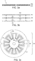
Figures 3a - 3c show various views of an embodiment stator of an agitation system of the appliance offigure 1 ; -
Figures 4a - 4e show plan views of embodiment arrangements for electrically conductive portions of the stator offigure 3 , in particular the arrangements may in one example be taken as being to scale, i.e. 1:1. - An appliance for foaming 2, an example of which is illustrated in
figure 1 , comprises at a first level thereof: abase unit 4 to transmit torque to a rotary agitator; acontainer 6 to contain liquid for end user consumption; arotary agitator 8 to foam said liquid, which are described sequentially as follows. - The
base unit 4 transmits torque to therotary agitator 8 by means of a magnetic field, and comprises at a first level thereof: ahousing 10;container mounting portion 12;agitation system 14; optionally aheater 16;control system 18, which are sequentially described as follows. - The
housing 10 houses and supports said first level components and comprises: abase 22 for abutment of a horizontally arranged support surface; a body 20 for mounting thereto the other first level components. - The
container mounting portion 12 is operable to mount thecontainer 6 to thebase unit 4. Thecontainer mounting portion 12 may be configured for permanent mounting of a container, e.g. it comprises a surface for locating the container to which the container can be bonded. Preferably thecontainer mounting portion 12 is configured for removable attachment to the container, e.g. it comprises a force fit or screw fit. An advantage of a removable attachment is that thecontainer 6 can be detached from thebase unit 4 for cleaning. The mountingportion 12 may comprise the stator with an optional a protective coating (e.g. an insulating lacquer or a glass fibre epoxy resin) on an outer surface thereof for mounting thecontainer 6 thereon. - The
agitation system 14 is operable to foam liquid in thecontainer 6 by mechanical agitation, in particular by transmission of torque via a magnetic field to arotary agitator 8, and comprises: astator 24; arotary agitator 8; anoptional core 30. - The
stator 24 is operable to receive phased electrical energy and to generate therefrom a rotating magnetic field. Thestator 24 comprises at least one circuit board with electrically conductive portions formed thereon and is discussed in more detail later on. - The
rotary agitator 8 comprises an array of magnetic poles that are circumferentially disposed about an axis of rotation for interaction with the rotating magnetic field generated by thestator 24.Agitator magnets 26 of therotary agitator 8 form said poles and comprise a magnetically hard material capable of a persistent magnetic field. Themagnets 8 are configured the transmission of torque derived from their interaction with the rotating magnetic field to the remainder of therotary agitator 8. Themagnets 26 may comprise discrete units with each comprising a north and south pole. Alternatively one or more of the units may be integrated, e.g. in an annular ring. Other components of therotary agitator 8 are discussed in more detail later on. - The
optional core 30 is for enhancing the rotating magnetic field and typically comprises a ferromagnetic metal such as iron. Thecode 30 is in general an axially arranged toroid or annular ring positioned proximal a face of thestator 24 that is distal thecontainer 6. - The optional heater is operable to 16 heat the liquid in the
container 6. Preferably theheater 16 comprises an induction coil operable to heat by electromagnetic induction therotary agitator 8. Alternatively it may heat thecontainer 6, e.g. the heater comprises a resistive element for heating by conduction. - The
control system 18, an example of which is illustrated infigure 2 , is operable to control theagitation system 14 and optional heater, and generally comprises: auser interface 32;optional sensors 34;processor 36;power supply 38, which are described sequentially. - The
user interface 32 comprises hardware to enable an end user to interface with theprocessor 36 and hence is operatively connected thereto. More particularly: the user interface receives commands from a user; a user interface signal transfers the said commands to theprocessor 36 as an input. The commands may, for example, be an instruction to execute a foaming process and/or a heating process. The hardware of theuser interface 32 may comprise any suitable device(s), for example, the hardware comprises one or more of the following: buttons, such as a joystick button or press button; joystick; LEDs; graphic or character LDCs; graphical screen with touch sensing and/or screen edge buttons. -
Optional sensors 34 are operatively connected to theprocessor 36 to provide an input for monitoring said process. Thesensors 40 typically comprise one or more of the following: liquid temperature sensors; liquid level sensors; position sensors (e.g. hall sensors) for sensing a position of the magnets of therotary agitator 8 with respect to the stator as will be discussed. - The
processor 36 is generally operable to: receive an input, i.e. the commands from theuser interface 32 and/or from thesensors 34; process the input according to program code stored on a memory unit (or programmed logic); provide an output, which is generally the said foaming process and/or a heating process. The process may be executed with open-loop control, or more preferably with closed-loop control using the input signal from thesensors 34 as feedback. Theprocessor 36 generally comprises memory, input and output system components, which are arranged as an integrated circuit, typically as a microprocessor or a microcontroller. Theprocessor 36 may comprise other suitable integrated circuits, such as: an ASIC; a programmable logic device such as an FPGA; an analogue integrated circuit such as a controller. Theprocessor 36 may also comprise one or more of the aforementioned integrated circuits, i.e. multiple processors. An example of a suitable component of a processor for stator control is theESCON 36/3 motor controller by Maxon, which may be controlled by a further processor. - The
processor 36 generally comprises a memory unit for storage of the program code and optionally data. The memory unit typically comprises: a non-volatile memory e.g. EPROM, EEPROM or Flash for program code and operating parameter storage; volatile memory (RAM) for data storage. The memory unit may comprise separate and/or integrated (e.g. on a die of the processor) memory. - The
power supply 38 is operable to supply electrical energy to theprocessor 36,agitation system 14 andheater 16. Thepower supply 38 may comprise various means, such as a battery or a unit to receive and condition a mains electrical supply. - The
container 6, and example of which is illustrated infigure 1 , is operable to contain the liquid for foaming. Typically the container has a capacity of 0.2 - 0.5 litres. Thecontainer 6 may be cylindrical (6). The container is generally formed of a material that is suitably transparent to a magnetic field, e.g. glass. - The liquid to be foamed in the container is generally any potable liquid including foodstuffs. Typically it is milk or comprises milk.
- The
rotary agitator 8, an example of which is illustrated infigure 1 , is operable to rotate to agitate the liquid in thecontainer 6 to effect its foaming. Therotary agitator 8 comprises: an axially extendingbody 40; asupport portion 42, radially extending from saidbody 40 for supporting theagitation portion 28 and theagitator magnets 26. Theagitation portion 28 may be contoured (as illustrated) or otherwise formed (e.g. comprising holes) to effect fluid agitation upon rotation. Thebody 40 comprises at an end thereof a location member configured to engage with a complimentary location portion of thecontainer 6, e.g. an extension on one of thebody 40 orcontainer 6 for insertion into a cavity on the other of thebody 40 orcontainer 6. - The arrangement and pole configuration of the
agitator magnets 26 of therotary agitator 8 is complementary to the poles of thestator 24, e.g. for the later discussed example stator configuration shown infigures 3 and4 , wherein the stator comprises 8 poles, i.e. 4 pole pairs, there are the same number of poles in the rotary agitator, which are arranged at a complimentary radial distance from the centre of rotation of the magnetic field. - The
stator 24, an idealisation of which is shown infigure 3 , comprises acircuit board 44 and electricallyconductive portions 46 arranged thereon. Thestator 24 may be arranged proximal a base of thecontainer 6 such that it is in operative proximity to therotary agitator 8, and example of such an arrangement is shown infigure 1 . In particular, it may fully or at least partially overlap (e.g. by covering at least 80% or 90% of the surface area of the base) said base of thecontainer 6. Typically thestator 24 is disc shaped with the axis of rotation of the associated magnetic field arranged at a centre thereof, however it will be appreciated that it may comprise other shapes. The diameter of the stator (when in disc form) may be 5 cm - 15cm. The thickness of an individual circuit board is selected for suitable thermal conduction, e.g. 1 - 2, such as 1.6mm ± 0.15mm. - The electrically
conductive portions 46 and circuit board(s) 44 may have various configurations as will be discussed. They are arranged to effect a multipolar (e.g. 2, 3, 4, 6 or more pole pairs), multiphase (e.g. 2, 3, 4 or more phase) motor configuration, which incorporates a rotor comprising theagitator magnets 26 of therotary agitator 8. More particularly, the stator and rotor are configured to effect a brushless DC or AC synchronous motor configuration. The electricallyconductive portions 46 are arranged to defineactive portions 48 for generation of the magnetic poles. The poles are connected in phases, whereby the individual phases can be switched sequentially to effect rotation of a magnetic field. In particular and active portion is configured to generate one pole (i.e. with a magnetic field vector which is in the north or south direction) of a pole pair. - In a first embodiment stator (not shown) the electrically
conductive portions 46 are arranged on one face of asignal circuit board 44. As an example, they are arranged with the active portions thereof extending circumferentially and sequentially in phase order, e.g. a 3 phase configuration, withphase 1, 2, 3 circumferentially extending. - In a second embodiment stator (not shown) the electrically
conductive portions 46 are arranged on both faces of asingle circuit board 44. As an example, the aforesaid arrangement for a single face is repeated on both faces of saidboard 44. - In a preferred third embodiment stator, an example of which is shown in
figure 3 , the stator comprises a plurality of said circuit boards, whereby said boards are arranged in the form of a stack, whereby the electricallyconductive portions 46 are formed on one or both sides of the associatedcircuit boards 44. - It will be appreciated that adjacent faces of said boards can be electrically isolated by means of an electrically insulating coating such as a glass fibre epoxy resin, e.g. prepreg TU-768 or TU-768P by Taiwan Union Corporation Technology. In the example the stack comprises 3 boards, 44A, 44B, 44C, it will be appreciated that any suitable number of boards can be utilised, e.g. 4 or 6. In the following, further exemplary arrangements of the preferred third embodiment will be discussed.
- The electrically
conductive portions 46 of different faces are interconnected by vias 50 thereof, which are preferably arranged distal said active portions 50 (i.e. a connecting portion of anelectrically conduction portion 46 connects a via 50 with an active portion 48). More particularly, the vias 50 can be arranged proximal a periphery of thecircuit boards 44 and/or proximal a centre of thecircuit boards 44. The vias 50 are generally of the through hole type (e.g. extending through one or more circuit boards), however other suitable arrangements are envisaged, e.g. a blind, castellated hole type. An example of such an arrangement is shown infigure 4a , whereby via 50A is proximal a periphery and via 50B is proximal a centre of theboard 44. - The electrically
conductive portions 46 are generally complimentary in shape, i.e. each face comprises the same arrangement, but to achieve the different phases the faces are rotationally offset. As an example of such an arrangement (not shown) two circuit boards have arranged on three faces different phases, with each phase having 8 active portions providing 4 pole pairs, and being rotationally offset from the first phase by 30 degrees. - In the following the third embodiment is described as having only one phase on a face.
- In the last example of the third embodiment, a phase was arranged on a single face, however in a preferred example of the third embodiment a phase may be distributed over a plurality of faces, e.g. 2, 3 or 4 faces. In this way complementary
active portions 48 can be layered to increase current density and field strength. -
Figures 3a and 3b illustrate such a preferred example, wherein there are three circuit boards 44A, 44B, 44C, with the electricallyconductive portions 46 arranged on each face, i.e. utilising all 6 faces (it will be appreciated that 6 circuit boards may alternatively be used with a single face of each utilised) to define 3 phases. In particular: phase 1 is arranged on the outer faces 52A, 52F of the outer circuit boards 44A, 44C;phase 2 is arranged on the inner faces 52B, 52E of the outer circuit boards 44A, 44C; phase 3 is arranged on the faces 52C, 52D of the inner circuit board 44B. In this way each phase is symmetrically disposed about a central plane, which in this example is centrally though the inner circuit board 44B. It will be appreciated that the said symmetric arrangement can be extended to different numbers ofcircuit boards 44 and phase arrangements, e.g. a four phase arrangement arranged with a phase over two faces and fourcircuit boards 44 with both faces used. The symmetric arrangement is advantageous since the strength of the magnetic field at therotary agitator 8 is balanced, which would not be the case if for example a first phase was arranged on the two faces most proximal the rotary agitator, and a third phase was arranged on the two faces most distal therotary agitator 8. - Considering the arrangement of the
active portions 48 in more detail, when a phase is split over several faces the superposedactive portions 48 of the same phase, which are arranged on different faces, are generally complimentary (i.e. they generate a pole with a magnetic field vector of the same direction). The other phases can be arranged in the same manner as per the first phase, but rotationally offset therefrom. Referring to the example infigure 4 to illustrate this arrangement: the two electrically conductive portion arrangements that comprise phase 1 are shown infigures 4a and 4b ,figure 4c shows their supposition;phase 2 comprises the same arrangement, but rotated through 30 degrees, the supposition of the two electrically conductive portion arrangements that comprisephase 2 are shown infigure 4d ; phase 3 comprises the same arrangement, but rotated through 60 degrees, the supposition of the two electrically conductive portion arrangements that comprise phase 3 are shown infigure 4e . - The
active portions 48 are configured to generate a magnetic field vector in a first direction, or are configured to generate a magnetic field vector in a second direction, whereby said configurations alternate on a face to define a plurality of poles. Referring to the example phase shown infigures 4a and 4b: figure 4a comprises 8 active portions, whereby the electrical energy (as indicated in the figures by the direction of the current I according to conventional flow notation) is transmitted thereto at via 50A and therefrom at via 50B, accordingly the field vector at theactive portion 48 most proximal via 50A is out of the page in the associated region (as indicated), and into the page at the most proximalactive portion 48 in the anticlockwise direction and so on as indicated; theactive portions 48 offigure 4b are connected to those offigure 4b by means of the vias 50B and 50C hence the current is in a different circumferential direction such that the field vector is in the same direction in the superposed active portions shown infigure 4c . Accordingly, in the example theactive portions 48 of the associated faces of a phase are rotationally offset by an amount corresponding to an active portion and the active portions between said faces are interconnected such that a current there through is in an opposed direction such that the magnetic field vector generated by superposed active portions is in the same direction. - Generally an
active portion 48 comprises two substantially radially extending portions that are interconnected by interconnecting portions. The said radially extending portions are typically 1 - 2 cm in length and 0.5 - 1 cm in width. The said radially extending portions comprise a plurality of tracks to control the current flow direction, typically there are 5 - 10 tracks. In particular the tracks may vary in width, for example, as illustrated infigure 4 , the tracks are narrower and more densely packed along the radially extending portions. Advantageously, the increased width of the interconnecting portions enables improved heat dissipation. - As shown in
figure 4a , a radially extending portion is shared between adjacentactive portions 48 on the same face. Moreover, the radially extending portions are interconnected alternating between proximal a periphery and a centre of the board, e.g. to form a U shape, whereby the interconnecting side alternates such that two adjacent active portions form an S shape. Alternatively put, an active portion comprises two sectorialy arranged radially extending portions, which are serially interconnected with neighbouring active portions. The radially extending portions generally overlap providing a high current density and thus magnetic field strength, an example of which is illustrated infigure 4c . In particular, to achieve the same polarity of the magnetic field the direction of the current through overlapping radially extending portions is this same. For the superposed active portions distributed on different faces: the radially extending portions can be interconnected on one face proximal a periphery of the board, the radially extending portions can be interconnected on another face proximal a centre of the board, an example of which is illustrated infigure 4c . - The
active portions 48 may comprise various other arrangements (not show and including for the first and second embodiment stator), for example, they may be arranged in a substantially rectangular shape, with a via arranged at an interior and outer of said rectangle for connection. - The
processor 36 is configured to control the current applied through the phases. The angular frequency of the generated magnetic field may be variable and/or constant, i.e. a phase locked loop, with a reference frequency. The position of therotary agitator 8 can be commutated by position sensors such as an: optical encoder; magnetic encoder (e.g. a resolver, synchro etc.); hall effect sensor, with the latter being preferable due to cost and size. -
- 4 Base unit
- 10 Housing
- 20 Body
- 22 Base
- 12 Container mounting portion
- 14 Agitation system
- 24 Stator
44 Circuit board
52 Face- 46 Electrically conductive portion
48 Active portion - 50 Vias
- 46 Electrically conductive portion
- 26 agitator magnets
- 28 agitation portion (of agitator 8)
- 30 Core
- 24 Stator
- 16 Heater
- 18 Control system
- 32 User interface
- 34 Sensors
- 36 Processor
- 38 Power supply
- 10 Housing
- 6 Container
-
8 Rotary Agitator
- 40 Body
- 42 Support portion
- 26 agitator magnets (of agitation system 14)
- 28 agitation portion (of agitation system 14)
Claims (13)
- An appliance (2) to foam a liquid for consumption, the appliance comprising:a container mounting portion (12) to mount thereto a container (6) to contain said liquid;an agitation system (14) configured to foam said liquid, said system comprising a stator (24) arranged external a mounted container, said stator configured to generate a rotating magnetic field for transmission of torque to rotate a rotary agitator (8) arranged in a mounted container,said stator (24) comprising a circuit board (44) with electrically conductive portions (46) formed thereon,characterized in that the electrically conductive portions are connected with at least a two phase configuration, each phase being arranged such that a face (52) of the circuit board(s) comprising a phase comprises a single phase only.
- The appliance according to the directly preceding claim, wherein the circuit board (44) comprises electrically conductive portions (46) formed on one or both faces of the circuit board.
- The appliance according to either of the preceding claims, wherein the stator (24) comprises a plurality of said circuit boards, whereby said circuit boards are arranged as a laminate.
- The appliance according to the directly preceding claim, wherein the electrically conductive portions (46) of each phase are complimentary in shape to each other and are rotationally offset to each other.
- The appliance according to any of the preceding claims, wherein a phase is distributed over a plurality of faces.
- The appliance according to the directly preceding claim, wherein the phases are symmetrically disposed about a central plane, the central plane being arranged centrally in a through-thickness direction of the circuit board(s).
- The appliance according to any of the preceding claims, wherein the electrically conductive portions (46) are arranged into active portions (48), whereby each active portion is configured to generate a magnetic pole for said torque transmission.
- The appliance according to the directly preceding claim, wherein the electrically conductive portions (46) are connected by vias (50) arranged distal said active portions.
- The appliance according to either of the directly preceding claims, when dependent on claim 5, wherein the active portions that comprise a phase that are arranged on different faces are configured such that superposed active portions generate a magnetic field vector in the same direction, whereby said direction alternates between adjacent superposed active portions to define a plurality of poles.
- The appliance according to the directly preceding claim, wherein the different faces comprising a phase each have substantially the same shape of active portion and are rotationally offset by an amount corresponding to an active portion.
- The appliance according to any of the preceding claims, wherein the stator (24) extends over a substantial portion of a base of a mounted container.
- The appliance according to any of the preceding claims further comprising: a container (6) to contain said liquid and a rotary agitator (8) for arrangement in said container, wherein the rotary agitator comprises one or more agitator magnets (26) defining magnetic poles for transmission of torque to the rotary agitator from the magnetic field generated by the stator (24).
- A method of foaming a liquid for consumption using the appliance (2) according to any of the preceding claims, said method comprising:generating a rotating magnetic field by applying electrical energy to electrically conductive portions (46) of a stator (24) formed on a circuit board (44);rotating a rotary agitator (8) arranged in a container (6) for containing liquid by applying a torque from said field to the rotary agitator (8).
Applications Claiming Priority (2)
| Application Number | Priority Date | Filing Date | Title |
|---|---|---|---|
| EP15178192 | 2015-07-24 | ||
| PCT/EP2016/066268 WO2017016847A1 (en) | 2015-07-24 | 2016-07-08 | Appliance for foaming beverage or foodstuff |
Publications (2)
| Publication Number | Publication Date |
|---|---|
| EP3324801A1 EP3324801A1 (en) | 2018-05-30 |
| EP3324801B1 true EP3324801B1 (en) | 2019-04-17 |
Family
ID=53773264
Family Applications (1)
| Application Number | Title | Priority Date | Filing Date |
|---|---|---|---|
| EP16736203.7A Active EP3324801B1 (en) | 2015-07-24 | 2016-07-08 | Appliance for foaming beverage or foodstuff |
Country Status (12)
| Country | Link |
|---|---|
| US (1) | US10905287B2 (en) |
| EP (1) | EP3324801B1 (en) |
| JP (1) | JP2018524105A (en) |
| CN (1) | CN107847084B (en) |
| AU (1) | AU2016299711A1 (en) |
| BR (1) | BR112017028585A2 (en) |
| CA (1) | CA2989512A1 (en) |
| ES (1) | ES2727556T3 (en) |
| PT (1) | PT3324801T (en) |
| RU (1) | RU2018106687A (en) |
| TR (1) | TR201908052T4 (en) |
| WO (1) | WO2017016847A1 (en) |
Families Citing this family (27)
| Publication number | Priority date | Publication date | Assignee | Title |
|---|---|---|---|---|
| CN108652404A (en) * | 2018-04-26 | 2018-10-16 | 武汉理工大学 | A kind of magnetic force direct-drive type blender |
| WO2020120504A1 (en) | 2018-12-13 | 2020-06-18 | Tetra Laval Holdings & Finance S.A. | A mixer for a food product |
| CN110354704B (en) * | 2019-03-14 | 2021-11-30 | 中国石油天然气股份有限公司 | Foam generating device |
| JP2022516632A (en) * | 2019-04-10 | 2022-03-01 | シャークニンジャ オペレーティング エルエルシー | Food processing system |
| CN112090336A (en) * | 2020-07-15 | 2020-12-18 | 齐喝彩(上海)管理咨询有限公司 | Unmanned water bar agitating unit of intelligence |
| IT202200001304A1 (en) * | 2022-01-26 | 2023-07-26 | Ali Group Srl Carpigiani | MACHINE FOR THE TREATMENT OF LIQUID OR SEMI-LIQUID FOOD PRODUCTS AND METHOD OF FOOD TREATMENT OF A FOOD MIXTURE. |
| US11647860B1 (en) | 2022-05-13 | 2023-05-16 | Sharkninja Operating Llc | Flavored beverage carbonation system |
| US12096880B2 (en) | 2022-05-13 | 2024-09-24 | Sharkninja Operating Llc | Flavorant for beverage carbonation system |
| US11751585B1 (en) | 2022-05-13 | 2023-09-12 | Sharkninja Operating Llc | Flavored beverage carbonation system |
| CN119403454A (en) | 2022-05-13 | 2025-02-07 | 尚科宁家运营有限公司 | Agitators for carbonation systems |
| US12213617B2 (en) | 2022-05-13 | 2025-02-04 | Sharkninja Operating Llc | Flavored beverage carbonation process |
| US12005404B2 (en) | 2022-08-22 | 2024-06-11 | Sharkninja Operating Llc | Beverage carbonation system flow control |
| US12539500B2 (en) | 2022-08-31 | 2026-02-03 | Sharkninja Operating Llc | Additive containers |
| US12103840B2 (en) | 2022-11-17 | 2024-10-01 | Sharkninja Operating Llc | Ingredient container with sealing valve |
| US11738988B1 (en) | 2022-11-17 | 2023-08-29 | Sharkninja Operating Llc | Ingredient container valve control |
| US11745996B1 (en) | 2022-11-17 | 2023-09-05 | Sharkninja Operating Llc | Ingredient containers for use with beverage dispensers |
| US11634314B1 (en) | 2022-11-17 | 2023-04-25 | Sharkninja Operating Llc | Dosing accuracy |
| US12084334B2 (en) | 2022-11-17 | 2024-09-10 | Sharkninja Operating Llc | Ingredient container |
| CN219183435U (en) * | 2022-12-22 | 2023-06-16 | 广东辉骏科技集团有限公司 | Coffee machine with stirring function |
| USD1091308S1 (en) | 2022-12-23 | 2025-09-02 | Sharkninja Operating Llc | Ingredient container |
| USD1092208S1 (en) | 2022-12-23 | 2025-09-09 | Sharkninja Operating Llc | Cap of ingredient container |
| US11925287B1 (en) | 2023-03-22 | 2024-03-12 | Sharkninja Operating Llc | Additive container with inlet tube |
| US11871867B1 (en) | 2023-03-22 | 2024-01-16 | Sharkninja Operating Llc | Additive container with bottom cover |
| US12116257B1 (en) | 2023-03-22 | 2024-10-15 | Sharkninja Operating Llc | Adapter for beverage dispenser |
| US12005408B1 (en) | 2023-04-14 | 2024-06-11 | Sharkninja Operating Llc | Mixing funnel |
| WO2024254837A1 (en) | 2023-06-16 | 2024-12-19 | Sharkninja Operating Llc | Carbonation mixing nozzles |
| CN120049656A (en) * | 2023-11-27 | 2025-05-27 | 广东美的生活电器制造有限公司 | Food processor and motor |
Family Cites Families (8)
| Publication number | Priority date | Publication date | Assignee | Title |
|---|---|---|---|---|
| JPH08223831A (en) | 1995-02-10 | 1996-08-30 | Toshiba Corp | Iron cores and rotor cores for rotating electrical machines |
| EP1564864A4 (en) | 2002-11-18 | 2006-12-13 | Seiko Epson Corp | BRUSHLESS MOTOR STATOR, BRUSHLESS MOTOR EQUIPPED WITH THIS STATOR AND SPOOL STRUCTURE |
| JP4569839B2 (en) | 2007-05-25 | 2010-10-27 | 株式会社デンソー | AC motor |
| CN102148544B (en) | 2010-02-09 | 2013-04-17 | 姚加章 | Multigap series magnetic disc-embedded type motor |
| EP2671306B1 (en) | 2011-01-31 | 2015-08-05 | Hitachi Koki Co., Ltd. | Disk motor, electric working machine including disk motor and method for manufacturing disk motor |
| WO2014009858A1 (en) * | 2012-07-12 | 2014-01-16 | Koninklijke Philips N.V. | Apparatus for agitating liquid foodstuff |
| FR2994038B1 (en) | 2012-07-27 | 2017-04-28 | David Libault | ELECTRIC MOTOR WITH AXIAL FLUX |
| CN104567651A (en) | 2014-12-16 | 2015-04-29 | 中国科学院苏州生物医学工程技术研究所 | PCB planar differential inductive angular displacement sensor |
-
2016
- 2016-07-08 CN CN201680040945.3A patent/CN107847084B/en active Active
- 2016-07-08 JP JP2018500762A patent/JP2018524105A/en not_active Withdrawn
- 2016-07-08 EP EP16736203.7A patent/EP3324801B1/en active Active
- 2016-07-08 PT PT16736203T patent/PT3324801T/en unknown
- 2016-07-08 BR BR112017028585A patent/BR112017028585A2/en not_active Application Discontinuation
- 2016-07-08 AU AU2016299711A patent/AU2016299711A1/en not_active Abandoned
- 2016-07-08 RU RU2018106687A patent/RU2018106687A/en not_active Application Discontinuation
- 2016-07-08 US US15/746,190 patent/US10905287B2/en active Active
- 2016-07-08 ES ES16736203T patent/ES2727556T3/en active Active
- 2016-07-08 CA CA2989512A patent/CA2989512A1/en not_active Abandoned
- 2016-07-08 WO PCT/EP2016/066268 patent/WO2017016847A1/en not_active Ceased
- 2016-07-08 TR TR2019/08052T patent/TR201908052T4/en unknown
Non-Patent Citations (1)
| Title |
|---|
| None * |
Also Published As
| Publication number | Publication date |
|---|---|
| CN107847084B (en) | 2021-04-13 |
| US10905287B2 (en) | 2021-02-02 |
| CA2989512A1 (en) | 2017-02-02 |
| AU2016299711A1 (en) | 2017-12-14 |
| RU2018106687A3 (en) | 2019-10-10 |
| US20180206678A1 (en) | 2018-07-26 |
| PT3324801T (en) | 2019-07-19 |
| EP3324801A1 (en) | 2018-05-30 |
| CN107847084A (en) | 2018-03-27 |
| JP2018524105A (en) | 2018-08-30 |
| WO2017016847A1 (en) | 2017-02-02 |
| ES2727556T3 (en) | 2019-10-17 |
| BR112017028585A2 (en) | 2018-09-04 |
| TR201908052T4 (en) | 2019-06-21 |
| RU2018106687A (en) | 2019-08-26 |
Similar Documents
| Publication | Publication Date | Title |
|---|---|---|
| US10905287B2 (en) | Appliance for foaming beverage or foodstuff | |
| US10702835B2 (en) | Appliance for foaming beverage or foodstuff | |
| US11166593B2 (en) | Food and beverage processing device comprising a magnetic coupling | |
| US11490767B2 (en) | Apparatus for agitating liquid foodstuff | |
| CN101951817B (en) | Automatic milk foamer | |
| RU2007121688A (en) | METHOD FOR PREPARING FOAM FROM FOOD LIQUID AND DEVICE FOR ITS IMPLEMENTATION | |
| CN107771047A (en) | The impeller of food processor | |
| CN205286123U (en) | An electromagnetic heating milk frother | |
| CN106489297A (en) | Induction heating apparatus, method and induced cooking utensils for operating induction heating apparatus | |
| JP2015150424A5 (en) | ||
| WO2014013738A1 (en) | Brushless motor | |
| CN115734729A (en) | Food container | |
| CN115734726A (en) | Food container | |
| JP2016007247A (en) | Mixing adapter | |
| JPH11127559A (en) | AC energy converter | |
| CN119679311A (en) | A segmented delivery mechanism and cooking device |
Legal Events
| Date | Code | Title | Description |
|---|---|---|---|
| STAA | Information on the status of an ep patent application or granted ep patent |
Free format text: STATUS: THE INTERNATIONAL PUBLICATION HAS BEEN MADE |
|
| PUAI | Public reference made under article 153(3) epc to a published international application that has entered the european phase |
Free format text: ORIGINAL CODE: 0009012 |
|
| STAA | Information on the status of an ep patent application or granted ep patent |
Free format text: STATUS: REQUEST FOR EXAMINATION WAS MADE |
|
| 17P | Request for examination filed |
Effective date: 20180226 |
|
| AK | Designated contracting states |
Kind code of ref document: A1 Designated state(s): AL AT BE BG CH CY CZ DE DK EE ES FI FR GB GR HR HU IE IS IT LI LT LU LV MC MK MT NL NO PL PT RO RS SE SI SK SM TR |
|
| AX | Request for extension of the european patent |
Extension state: BA ME |
|
| DAV | Request for validation of the european patent (deleted) | ||
| DAX | Request for extension of the european patent (deleted) | ||
| GRAP | Despatch of communication of intention to grant a patent |
Free format text: ORIGINAL CODE: EPIDOSNIGR1 |
|
| STAA | Information on the status of an ep patent application or granted ep patent |
Free format text: STATUS: GRANT OF PATENT IS INTENDED |
|
| INTG | Intention to grant announced |
Effective date: 20181207 |
|
| GRAS | Grant fee paid |
Free format text: ORIGINAL CODE: EPIDOSNIGR3 |
|
| GRAA | (expected) grant |
Free format text: ORIGINAL CODE: 0009210 |
|
| STAA | Information on the status of an ep patent application or granted ep patent |
Free format text: STATUS: THE PATENT HAS BEEN GRANTED |
|
| AK | Designated contracting states |
Kind code of ref document: B1 Designated state(s): AL AT BE BG CH CY CZ DE DK EE ES FI FR GB GR HR HU IE IS IT LI LT LU LV MC MK MT NL NO PL PT RO RS SE SI SK SM TR |
|
| REG | Reference to a national code |
Ref country code: GB Ref legal event code: FG4D |
|
| REG | Reference to a national code |
Ref country code: CH Ref legal event code: EP |
|
| REG | Reference to a national code |
Ref country code: DE Ref legal event code: R096 Ref document number: 602016012613 Country of ref document: DE |
|
| REG | Reference to a national code |
Ref country code: AT Ref legal event code: REF Ref document number: 1120632 Country of ref document: AT Kind code of ref document: T Effective date: 20190515 Ref country code: IE Ref legal event code: FG4D |
|
| REG | Reference to a national code |
Ref country code: NL Ref legal event code: PD Owner name: SOCIETE DES PRODUITS NESTLE S.A.; CH Free format text: DETAILS ASSIGNMENT: CHANGE OF OWNER(S), MERGE; FORMER OWNER NAME: NESTEC S.A. Effective date: 20190620 |
|
| RAP2 | Party data changed (patent owner data changed or rights of a patent transferred) |
Owner name: SOCIETE DES PRODUITS NESTLE S.A. |
|
| REG | Reference to a national code |
Ref country code: CH Ref legal event code: PCOW |
|
| REG | Reference to a national code |
Ref country code: NL Ref legal event code: FP |
|
| REG | Reference to a national code |
Ref country code: PT Ref legal event code: SC4A Ref document number: 3324801 Country of ref document: PT Date of ref document: 20190719 Kind code of ref document: T Free format text: AVAILABILITY OF NATIONAL TRANSLATION Effective date: 20190712 |
|
| REG | Reference to a national code |
Ref country code: GB Ref legal event code: 732E Free format text: REGISTERED BETWEEN 20190801 AND 20190807 |
|
| PGFP | Annual fee paid to national office [announced via postgrant information from national office to epo] |
Ref country code: BE Payment date: 20190617 Year of fee payment: 4 Ref country code: NL Payment date: 20190712 Year of fee payment: 4 |
|
| REG | Reference to a national code |
Ref country code: LT Ref legal event code: MG4D |
|
| REG | Reference to a national code |
Ref country code: ES Ref legal event code: FG2A Ref document number: 2727556 Country of ref document: ES Kind code of ref document: T3 Effective date: 20191017 |
|
| PG25 | Lapsed in a contracting state [announced via postgrant information from national office to epo] |
Ref country code: FI Free format text: LAPSE BECAUSE OF FAILURE TO SUBMIT A TRANSLATION OF THE DESCRIPTION OR TO PAY THE FEE WITHIN THE PRESCRIBED TIME-LIMIT Effective date: 20190417 Ref country code: NO Free format text: LAPSE BECAUSE OF FAILURE TO SUBMIT A TRANSLATION OF THE DESCRIPTION OR TO PAY THE FEE WITHIN THE PRESCRIBED TIME-LIMIT Effective date: 20190717 Ref country code: AL Free format text: LAPSE BECAUSE OF FAILURE TO SUBMIT A TRANSLATION OF THE DESCRIPTION OR TO PAY THE FEE WITHIN THE PRESCRIBED TIME-LIMIT Effective date: 20190417 Ref country code: SE Free format text: LAPSE BECAUSE OF FAILURE TO SUBMIT A TRANSLATION OF THE DESCRIPTION OR TO PAY THE FEE WITHIN THE PRESCRIBED TIME-LIMIT Effective date: 20190417 Ref country code: HR Free format text: LAPSE BECAUSE OF FAILURE TO SUBMIT A TRANSLATION OF THE DESCRIPTION OR TO PAY THE FEE WITHIN THE PRESCRIBED TIME-LIMIT Effective date: 20190417 Ref country code: LT Free format text: LAPSE BECAUSE OF FAILURE TO SUBMIT A TRANSLATION OF THE DESCRIPTION OR TO PAY THE FEE WITHIN THE PRESCRIBED TIME-LIMIT Effective date: 20190417 |
|
| PGFP | Annual fee paid to national office [announced via postgrant information from national office to epo] |
Ref country code: TR Payment date: 20190702 Year of fee payment: 4 Ref country code: PT Payment date: 20190718 Year of fee payment: 4 Ref country code: ES Payment date: 20190801 Year of fee payment: 4 Ref country code: IT Payment date: 20190731 Year of fee payment: 4 |
|
| REG | Reference to a national code |
Ref country code: AT Ref legal event code: PC Ref document number: 1120632 Country of ref document: AT Kind code of ref document: T Owner name: SOCIETE DES PRODUITS NESTLE S.A., CH Effective date: 20190916 |
|
| REG | Reference to a national code |
Ref country code: BE Ref legal event code: PD Owner name: SOCIETE DES PRODUITS NESTLE S.A.; CH Free format text: DETAILS ASSIGNMENT: CHANGE OF OWNER(S), CESSION; FORMER OWNER NAME: NESTEC S.A. Effective date: 20190712 |
|
| PG25 | Lapsed in a contracting state [announced via postgrant information from national office to epo] |
Ref country code: RS Free format text: LAPSE BECAUSE OF FAILURE TO SUBMIT A TRANSLATION OF THE DESCRIPTION OR TO PAY THE FEE WITHIN THE PRESCRIBED TIME-LIMIT Effective date: 20190417 Ref country code: BG Free format text: LAPSE BECAUSE OF FAILURE TO SUBMIT A TRANSLATION OF THE DESCRIPTION OR TO PAY THE FEE WITHIN THE PRESCRIBED TIME-LIMIT Effective date: 20190717 Ref country code: GR Free format text: LAPSE BECAUSE OF FAILURE TO SUBMIT A TRANSLATION OF THE DESCRIPTION OR TO PAY THE FEE WITHIN THE PRESCRIBED TIME-LIMIT Effective date: 20190718 Ref country code: LV Free format text: LAPSE BECAUSE OF FAILURE TO SUBMIT A TRANSLATION OF THE DESCRIPTION OR TO PAY THE FEE WITHIN THE PRESCRIBED TIME-LIMIT Effective date: 20190417 Ref country code: PL Free format text: LAPSE BECAUSE OF FAILURE TO SUBMIT A TRANSLATION OF THE DESCRIPTION OR TO PAY THE FEE WITHIN THE PRESCRIBED TIME-LIMIT Effective date: 20190417 |
|
| PG25 | Lapsed in a contracting state [announced via postgrant information from national office to epo] |
Ref country code: IS Free format text: LAPSE BECAUSE OF FAILURE TO SUBMIT A TRANSLATION OF THE DESCRIPTION OR TO PAY THE FEE WITHIN THE PRESCRIBED TIME-LIMIT Effective date: 20190817 |
|
| REG | Reference to a national code |
Ref country code: DE Ref legal event code: R097 Ref document number: 602016012613 Country of ref document: DE |
|
| PG25 | Lapsed in a contracting state [announced via postgrant information from national office to epo] |
Ref country code: CZ Free format text: LAPSE BECAUSE OF FAILURE TO SUBMIT A TRANSLATION OF THE DESCRIPTION OR TO PAY THE FEE WITHIN THE PRESCRIBED TIME-LIMIT Effective date: 20190417 Ref country code: RO Free format text: LAPSE BECAUSE OF FAILURE TO SUBMIT A TRANSLATION OF THE DESCRIPTION OR TO PAY THE FEE WITHIN THE PRESCRIBED TIME-LIMIT Effective date: 20190417 Ref country code: SK Free format text: LAPSE BECAUSE OF FAILURE TO SUBMIT A TRANSLATION OF THE DESCRIPTION OR TO PAY THE FEE WITHIN THE PRESCRIBED TIME-LIMIT Effective date: 20190417 Ref country code: DK Free format text: LAPSE BECAUSE OF FAILURE TO SUBMIT A TRANSLATION OF THE DESCRIPTION OR TO PAY THE FEE WITHIN THE PRESCRIBED TIME-LIMIT Effective date: 20190417 Ref country code: EE Free format text: LAPSE BECAUSE OF FAILURE TO SUBMIT A TRANSLATION OF THE DESCRIPTION OR TO PAY THE FEE WITHIN THE PRESCRIBED TIME-LIMIT Effective date: 20190417 |
|
| PGFP | Annual fee paid to national office [announced via postgrant information from national office to epo] |
Ref country code: CH Payment date: 20190718 Year of fee payment: 4 |
|
| REG | Reference to a national code |
Ref country code: DE Ref legal event code: R082 Ref document number: 602016012613 Country of ref document: DE Representative=s name: MITSCHERLICH, PATENT- UND RECHTSANWAELTE PARTM, DE Ref country code: DE Ref legal event code: R081 Ref document number: 602016012613 Country of ref document: DE Owner name: SOCIETE DES PRODUITS NESTLE S.A., CH Free format text: FORMER OWNER: NESTEC S.A., VEVEY, CH |
|
| PLBE | No opposition filed within time limit |
Free format text: ORIGINAL CODE: 0009261 |
|
| STAA | Information on the status of an ep patent application or granted ep patent |
Free format text: STATUS: NO OPPOSITION FILED WITHIN TIME LIMIT |
|
| PG25 | Lapsed in a contracting state [announced via postgrant information from national office to epo] |
Ref country code: MC Free format text: LAPSE BECAUSE OF FAILURE TO SUBMIT A TRANSLATION OF THE DESCRIPTION OR TO PAY THE FEE WITHIN THE PRESCRIBED TIME-LIMIT Effective date: 20190417 Ref country code: SM Free format text: LAPSE BECAUSE OF FAILURE TO SUBMIT A TRANSLATION OF THE DESCRIPTION OR TO PAY THE FEE WITHIN THE PRESCRIBED TIME-LIMIT Effective date: 20190417 |
|
| 26N | No opposition filed |
Effective date: 20200120 |
|
| PG25 | Lapsed in a contracting state [announced via postgrant information from national office to epo] |
Ref country code: SI Free format text: LAPSE BECAUSE OF FAILURE TO SUBMIT A TRANSLATION OF THE DESCRIPTION OR TO PAY THE FEE WITHIN THE PRESCRIBED TIME-LIMIT Effective date: 20190417 Ref country code: LU Free format text: LAPSE BECAUSE OF NON-PAYMENT OF DUE FEES Effective date: 20190708 |
|
| PG25 | Lapsed in a contracting state [announced via postgrant information from national office to epo] |
Ref country code: IE Free format text: LAPSE BECAUSE OF NON-PAYMENT OF DUE FEES Effective date: 20190708 |
|
| REG | Reference to a national code |
Ref country code: CH Ref legal event code: PL |
|
| REG | Reference to a national code |
Ref country code: NL Ref legal event code: MM Effective date: 20200801 |
|
| GBPC | Gb: european patent ceased through non-payment of renewal fee |
Effective date: 20200708 |
|
| REG | Reference to a national code |
Ref country code: BE Ref legal event code: MM Effective date: 20200731 |
|
| PG25 | Lapsed in a contracting state [announced via postgrant information from national office to epo] |
Ref country code: GB Free format text: LAPSE BECAUSE OF NON-PAYMENT OF DUE FEES Effective date: 20200708 Ref country code: CH Free format text: LAPSE BECAUSE OF NON-PAYMENT OF DUE FEES Effective date: 20200731 Ref country code: LI Free format text: LAPSE BECAUSE OF NON-PAYMENT OF DUE FEES Effective date: 20200731 |
|
| PG25 | Lapsed in a contracting state [announced via postgrant information from national office to epo] |
Ref country code: CY Free format text: LAPSE BECAUSE OF FAILURE TO SUBMIT A TRANSLATION OF THE DESCRIPTION OR TO PAY THE FEE WITHIN THE PRESCRIBED TIME-LIMIT Effective date: 20190417 Ref country code: BE Free format text: LAPSE BECAUSE OF NON-PAYMENT OF DUE FEES Effective date: 20200731 |
|
| PG25 | Lapsed in a contracting state [announced via postgrant information from national office to epo] |
Ref country code: NL Free format text: LAPSE BECAUSE OF NON-PAYMENT OF DUE FEES Effective date: 20200801 |
|
| PG25 | Lapsed in a contracting state [announced via postgrant information from national office to epo] |
Ref country code: MT Free format text: LAPSE BECAUSE OF FAILURE TO SUBMIT A TRANSLATION OF THE DESCRIPTION OR TO PAY THE FEE WITHIN THE PRESCRIBED TIME-LIMIT Effective date: 20190417 Ref country code: HU Free format text: LAPSE BECAUSE OF FAILURE TO SUBMIT A TRANSLATION OF THE DESCRIPTION OR TO PAY THE FEE WITHIN THE PRESCRIBED TIME-LIMIT; INVALID AB INITIO Effective date: 20160708 Ref country code: PT Free format text: LAPSE BECAUSE OF NON-PAYMENT OF DUE FEES Effective date: 20210408 |
|
| PG25 | Lapsed in a contracting state [announced via postgrant information from national office to epo] |
Ref country code: IT Free format text: LAPSE BECAUSE OF NON-PAYMENT OF DUE FEES Effective date: 20200708 |
|
| REG | Reference to a national code |
Ref country code: ES Ref legal event code: FD2A Effective date: 20211129 |
|
| PG25 | Lapsed in a contracting state [announced via postgrant information from national office to epo] |
Ref country code: ES Free format text: LAPSE BECAUSE OF NON-PAYMENT OF DUE FEES Effective date: 20200709 |
|
| PG25 | Lapsed in a contracting state [announced via postgrant information from national office to epo] |
Ref country code: TR Free format text: LAPSE BECAUSE OF NON-PAYMENT OF DUE FEES Effective date: 20200708 Ref country code: MK Free format text: LAPSE BECAUSE OF FAILURE TO SUBMIT A TRANSLATION OF THE DESCRIPTION OR TO PAY THE FEE WITHIN THE PRESCRIBED TIME-LIMIT Effective date: 20190417 |
|
| REG | Reference to a national code |
Ref country code: AT Ref legal event code: MM01 Ref document number: 1120632 Country of ref document: AT Kind code of ref document: T Effective date: 20210708 |
|
| PG25 | Lapsed in a contracting state [announced via postgrant information from national office to epo] |
Ref country code: AT Free format text: LAPSE BECAUSE OF NON-PAYMENT OF DUE FEES Effective date: 20210708 |
|
| REG | Reference to a national code |
Ref country code: AT Ref legal event code: UEP Ref document number: 1120632 Country of ref document: AT Kind code of ref document: T Effective date: 20190417 |
|
| P01 | Opt-out of the competence of the unified patent court (upc) registered |
Effective date: 20230623 |
|
| PGFP | Annual fee paid to national office [announced via postgrant information from national office to epo] |
Ref country code: FR Payment date: 20250610 Year of fee payment: 10 |
|
| PGFP | Annual fee paid to national office [announced via postgrant information from national office to epo] |
Ref country code: DE Payment date: 20250604 Year of fee payment: 10 |