EP3324182A1 - Moisture measurement apparatus - Google Patents
Moisture measurement apparatus Download PDFInfo
- Publication number
- EP3324182A1 EP3324182A1 EP16002477.4A EP16002477A EP3324182A1 EP 3324182 A1 EP3324182 A1 EP 3324182A1 EP 16002477 A EP16002477 A EP 16002477A EP 3324182 A1 EP3324182 A1 EP 3324182A1
- Authority
- EP
- European Patent Office
- Prior art keywords
- neutron
- airship
- detector
- neutrons
- carrier gas
- Prior art date
- Legal status (The legal status is an assumption and is not a legal conclusion. Google has not performed a legal analysis and makes no representation as to the accuracy of the status listed.)
- Granted
Links
Images



Classifications
-
- G—PHYSICS
- G01—MEASURING; TESTING
- G01N—INVESTIGATING OR ANALYSING MATERIALS BY DETERMINING THEIR CHEMICAL OR PHYSICAL PROPERTIES
- G01N33/00—Investigating or analysing materials by specific methods not covered by groups G01N1/00 - G01N31/00
- G01N33/24—Earth materials
- G01N33/246—Earth materials for water content
-
- G—PHYSICS
- G01—MEASURING; TESTING
- G01N—INVESTIGATING OR ANALYSING MATERIALS BY DETERMINING THEIR CHEMICAL OR PHYSICAL PROPERTIES
- G01N23/00—Investigating or analysing materials by the use of wave or particle radiation, e.g. X-rays or neutrons, not covered by groups G01N3/00 – G01N17/00, G01N21/00 or G01N22/00
- G01N23/20—Investigating or analysing materials by the use of wave or particle radiation, e.g. X-rays or neutrons, not covered by groups G01N3/00 – G01N17/00, G01N21/00 or G01N22/00 by using diffraction of the radiation by the materials, e.g. for investigating crystal structure; by using scattering of the radiation by the materials, e.g. for investigating non-crystalline materials; by using reflection of the radiation by the materials
- G01N23/203—Measuring back scattering
- G01N23/204—Measuring back scattering using neutrons
Definitions
- the present invention relates to a moisture measurement apparatus, particularly a soil moisture measurement apparatus and a related method based on cosmic ray neutron probing (CRNP) and particularly based on cosmic ray induced atmospheric neutron probing.
- CRNP cosmic ray neutron probing
- neutrons and neutron probing or neutron sensing in the present application.
- Another field which requires the reliable determination of soil moisture content may be farming, particularly sustainable and precision farming. It is important for a farmer to know exact amounts of moisture contained in the soil for determining the correct/optimal amount of irrigation, for example. This may help to achieve optimal growing results, to avoid salting of the soil, to avoid flooding and to safe water which is particularly important in dry areas.
- soil moisture content has been determined by means of local contact-based (invasive) techniques.
- One such technique is based on weighing a portion of soil including soil moisture content, weighing the same portion of soil after heating and evaporating the moisture content. The moisture content is then determined by subtracting the measured weights from each other.
- soil moisture content may be determined by measuring the electrical resistance while applying an electrical field to a portion of soil.
- Other methods for detecting soil moisture content include time domain - or frequency domain reflectometry, which requires injecting a wire into a portion of soil.
- a Troxler detection head has been used to introduce neutrons locally into a portion of soil and to measure thermalization.
- the soil water content may also be estimated by means of satellite based systems detecting radio or optical signals. This allows to roughly scan large areas in view of hydrologic applications, as the altitude of satellites is extremely large compared to other systems.
- SNR signal to noise ratio
- An alternative non-invasive technique for measuring soil water content in the range of several square kilometers, related to weather observation, is based on optical spectral detection of the Earth's surface with satellites, known as remote sensing. Areas under clouds can hardly be probed using satellite based soil moisture content detection. The first centimeter of the soil may be probed with this method. Vertical inhomogeneity of soil moisture content further requires careful analysis of measured data using precise soil models.
- Cosmic ray neutron sensing or cosmic ray neutron probing (CRNP) - another non-invasive contactless technique to identify soil moisture content - has recently been introduced for the first time (in 2008). This method is based on the detection of neutron density related to such neutrons which have been reflected/scattered back from the soil. These neutrons are particularly sensitive to and indicative of soil moisture content. Such neutrons are cosmic ray induced atmospheric neutrons. The origin of these neutrons is discussed in more detail further below.
- thermal neutron detectors have been applied for this technique (mainly produced by the company Hydroinnova). Such detectors can be installed at fixed positions or transported in a vehicle to provide a degree of mobility. Other means for providing a high degree of mobility have been reported, such as gyrocopters or microlights. Therefore, the benefits of transporting the detector at a high altitude during detection, such as probing a large area, can be exploited.
- the present invention relates to an apparatus and a respective method for probing moisture content and more particularly soil moisture content by means of detecting neutrons.
- the spatial range which may be covered by the invention (including the size of the observable area of typically multiple hectares and the special resolution) lies in a regime which has so far been challenging to be covered by means of conventional probing techniques.
- the size of the observable area is larger than for typical conventional local detecting systems.
- the spatial resolution achieved by the present disclosure is higher than for typical conventional satellite based detection systems.
- the apparatus and method according to the present disclosure may be applied for passive mobile large scale hydrological measurements, particularly for flood control and prevention and for farming and particularly for precision farming.
- the field of the present disclosure is however not limited to said application and may be extended to other meteorological and/or biological fields such as weather observation, observation of cloud and/or fog/mist development and/or water accumulation and/or vegetal cover and/or snow cover as well as the condition of snow fields.
- a moisture measurement apparatus for detecting moisture content, particularly soil moisture content.
- the apparatus comprising:
- Airships and related "lighter-than-air technologies" have long been known to provide multiple advantages, such as being eco-friendly and cheap due to low energy consumption, low noise production, ability to transport heavy loads from point to point, ability to move far distances while being flexible in reaching various altitudes and being mobile over impassable and rough terrain.
- airships are able to move/float over land at very low pace up to standing still with respect to the geological coordinate.
- airships are not required to be started from a starting-/landing strip. The restrictions regarding the starting and/or landing positions of airships are low, in general. Further, depending on the carrier gas used in the airship, the risk for accidents can be held very low.
- an airship for neutron sensing as it may float at altitudes which allow probing large surface areas and large spatial coverage. Such areas may possibly be located in impassable and rough terrain. This is of particular interest as the risk of landslip due to high soil water content is usually high at mountains and in mountainous countryside which is often rough and hard to approach. It is beneficial in view of versatility to use a technique for scanning large areas (i.e. several hectares and more) rather than using a technique which allows for local measurements for evaluating and observing the hydrological condition as well as the degree of saturation of soil water in a vast landscape. For example, an observation area of about one to ten hectares may be probed quickly and precisely using the apparatus according to the present invention.
- a scanned observation area may also be larger.
- the observation area to be scanned and probed may also be smaller, particularly in the case when the airship is fixed and/or tethered to a fixed position over the ground.
- the present invention allows scanning larger areas.
- the present invention provides a more reliable detection with a higher spatial resolution.
- mobile neutron sensing according to the present disclosure does not require a large-scale network of sensors at fixed positions, hence being less extensive and expensive in view of installation and maintenance.
- Mobile neutron sensing according to the present disclosure also allows a user to apply the technique wherever needed acutely.
- the present disclosure also allows to take into account soil moisture content present in several decimeters below the earth's surface, thus providing a more reliable conclusion about the soil's saturation with water.
- the at least one airship is at least partially filled with a carrier gas when floating.
- a carrier gas When the volume is at least partially filled with a carrier gas, the airship can adopt at least in parts its full size. In this case, the airship uses the buoyancy force for floating as the carrier gas is lighter than air.
- a gas-filled airship can exploit the buoyancy force at very high altitudes.
- the carrier gas at least partially serves as the at least one moderator medium.
- a gas which is used at least in parts as a carrier medium and as a moderator medium i.e. for slowing down the neutrons before detection
- fast neutrons are slowed down to kinetic energies at which they can effectively be detected by the neutron detector.
- the neutron detectors which are used for neutron sensing comprise a solid state moderator medium, such as polyethylene.
- a polyethylene moderator medium can weigh as much as 8 to 30 kg. Therefore the additional weight may be reduced or completely avoided if the carrier gas has a moderating function.
- the airship may simply carry the thermal neutron detector's weight and its own weight, as the carrier gas is lighter than air and does have the functions of carrying the apparatus and moderating the neutrons at the same time. Therefore, an efficient apparatus can be provided having a large detection volume, floating slowly at low altitudes and simply carrying the weight of the sensor if no additional equipment is to be carried. Energy consumption and costs may therefore be reduced.
- the carrier gas is at least partially one out of hydrogen, helium, heated air, methane, ammonia, neon, acetylene, diborane, carbon monoxide, nitrogen and ethene or a mixture thereof.
- a carrier gas which contains hydrogen atoms, such as hydrogen or methane, is efficient in moderating neutrons. Making use of such compounds is therefore beneficial, as they serve efficiently as the carrier gas and the moderator medium at the same time. Further, it is beneficial in some cases to use for example hydrogen gas instead of helium gas as a carrier gas, as hydrogen is more efficient in its buoyancy properties and less expensive. For safety reasons it may however also be favorable to provide helium gas instead of hydrogen gas, as it is inert and not explosive.
- the at least one neutron detector is at least partially surrounded by the carrier gas. If the neutron detector is at least partially surrounded by the carrier gas, the neutrons can be slowed down in the vicinity of the detector, particularly if the carrier gas is also used as the moderator medium.
- the gas phase which at least partially surrounds the detector may then substitute a moderator shell such as a polyethylene case or cover.
- the at least one neutron detector comprises at least one gas proportional detector, particularly a boron neutron converter and more particularly a Jalousie detector and/or a scintillation neutron detector and/or a semiconductor neutron detector.
- boron neutron converters 10 B solid state detector
- Jalousie detectors are far less expensive. Therefore, a probing interval can be substantially extended to long duration. Large areas of landscape may therefore be probed with boron neutron converters.
- 3 He is expensive and as a result only small amounts of 3 He may be provided in a detector such that only small areas of landscapes can be probed.
- boron detectors however, soil moisture content of a larger area and at a higher spatial resolution can be achieved during a typical probing interval of one day. It can also be beneficial to provide multiple detectors in view of expanding the probing intervals or further improving reliability. It cannot be excluded that, in some cases, it is beneficial to provide detectors based on other technologies (in addition or as an alternative to boron neutron converters), particularly if such detectors are cheaper and/or more reliable and/or having a longer life time.
- the apparatus further comprises at least one:
- conditions and/or features and/or functions of the apparatus such as float velocity, position, floating altitude, carrier gas pressure and/or detection of measures are controlled dynamically and/or in a predetermined manner by means of at least one control element out of a remote control, a computer, a smartphone, a satellite, or a base station and/or data may be exchanged between the control element and the apparatus.
- An operator may dynamically derive a condition of the soil and/or weather from the detected data when the data is exchanged between (elements of) the apparatus and control elements on the ground, such as a remote control and/or a computer/server.
- it may be advantageous to transfer data between detection elements and computers and/or servers, e.g. via mobile Internet, for instantaneous storage and/or analysis of the exchanged data.
- communication takes place between several control elements and the airship via a receiver or transceiver at the apparatus or airship.
- a GPS signal of satellites may be received by a receiver in the airship, the receiver may be connected to a computer either in/at the airship or on the ground such that the computer can derive the exact position and floating velocity. Based on such data, an operator can control the floating trajectory and/or pace of the airship.
- the present invention provides a method of detecting moisture content and particularly soil moisture content comprising the steps of:
- neutrons are at least partly moderated by means of the carrier gas.
- the neutron detector may be a gas proportional detector, particularly a boron neutron converter and more particularly a Jalousie detector and/or a scintillation neutron detector and/or a semiconductor neutron detector.
- the at least one neutron detector may be positioned substantially inside a gas filled volume of the airship.
- the method may comprise:
- the method may comprise:
- the method may comprise:
- a preferential altitude between 5 and 200 m allows screening a large area compared to areas probed with conventional techniques. Floating however at a low altitude - around 5 to 10 and up to 50 m - allows probing the soil moisture content locally with higher precision and improved spatial resolution. If larger areas are to be screened, possibly in rough terrain and/or above a city or a forest, the airship may float at higher altitudes, for example at altitudes of 100 to 300 m. Depending on the requirements, the airship can float at different altitudes. Therefore, the method of detecting soil moisture content in the said altitude range allows versatile applications for different requirements or limitations due to the landscape or the operator's desires.
- a dynamic control of the airship's position is favorable if an operator does not want to predetermine a trajectory.
- pre-setting a trajectory of the airship may be beneficial as automated aviation requires less man power and a remote control/computer autonomously controls the position and the pace of the airship. This may include that the airship can be operated as a drone.
- the airship may be fixed to a position with respect to the geographic coordinate if the development/change of a condition at a certain position/small area (instead of a large area) over a longer time span is required to be probed.
- a fixed position of the airship can be achieved by dynamically controlling and possibly correcting for drift due to wind or by tethering the airship by means of at least one rope to a fixed position on the ground.
- the rope may not only be used to fix the airship but also to move it in a controlled manner to a new position, if required.
- the airship may also be a balloon.
- the moisture measurement apparatus can be cost-effective, reliable, versatile, efficient, and handled in a straightforward manner, it may particularly be used in rough terrain, areas which often suffer ecological disasters and particular less developed countries which suffer poverty and a low degree of infrastructure. Such countries often experience ecological disasters related to flooding and landslip causing death of humans, animal stock and/or loss of property. Further, the moisture measurement apparatus may be applied by farmers to estimate the soil moisture content and to derive efficient/optimal amounts of irrigation. Again, less developed countries, often suffering water scarcity, may benefit in particular from the moisture measurement apparatus. The moisture measurement apparatus may therefore be configured to be used by either a private person, such as a farmer or a professional operator, such as a meteorologist or a person on behalf of the government or a company. The training for becoming an operator of the moisture measurement apparatus may therefore be simple depending on the requirements.
- Fig. 1 , Fig. 2 and Fig. 5 show a spatial three dimensional coordinate system, wherein the orthogonal directions are indicated by arrows related to the reference signs x, y, z.
- x and y refer to a horizontal plane or a surface at one particular altitude, i.e. for example a flat ground G, neglecting the earth's curvature in an approximation.
- z indicates the vertical direction.
- the arrow for the vertical direction z is directed "upwards", i.e. towards higher altitudes. In other words, the arrow is directed from the ground G of the earth towards the sky/top of the atmosphere.
- Fig. 1 schematically illustrates one embodiment of the invention, also containing features which are not essential for the invention. Such additional features may be indicated as being optional.
- some aspects - particularly the aspects related the dependent claims - as illustrated in the figures may not limit the scope of the invention, as such aspects are not required for realizing the invention according to the independent claim.
- an apparatus 1 for probing soil moisture content by means of detecting neutrons is described in the following. It is self-evident that a method for probing soil moisture content by means of detecting neutrons is covered by the same description.
- neutrons mostly cosmic ray induced atmospheric neutrons are regarded. However, also cosmic neutrons may be detected and should therefore be covered by the term.
- the moisture measurement apparatus 1 according to the present invention is configured to detect moisture content, preferably soil moisture content. Alternatively or additionally, it may be possible to also detect moisture content related to biological cover (grass, trees, bushes or forest), fog, mist, clouds, snow fields and other possible phenomena related to moisture and/or presence of water.
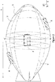
- the moisture measurement apparatus 1 comprises at least one airship 2 and at least one neutron detector 3, which is preferably positioned inside the airship as indicated in Fig. 1 and Fig. 2 .
- the neutron detector 3 is configured to detect particularly thermal neutrons. These thermal neutrons may result from slowing down faster neutrons to energies which can be efficiently detected by the neutron detector 3, as will be described in more detail below.
- the detector 3 can either be a gaseous hybrid detector with solid neutron converters like 10 B or a gaseous detector with 3 He for example.
- the detector 3 comprises several layers of boron carbide coatings on a cathode, Argon-CO 2 as a counting gas and a wire based anode, which is based on the principle of a proportional tube or a multi wire proportional chamber.
- the neutron detector 3 is described with respect to Fig. 1 and Fig. 2 which illustrate the apparatus 1 comprising one neutron detector 3.
- the neutron detector 3 may comprise a gas proportional detector.
- the neutron detector 3 may comprise a boron ( 10 B) neutron converter, particularly a Jalousie detector.
- the boron neutron detectors are less expensive.
- the preferred 10 B detector comprises a wire chamber and boron carbide converters being specifically designed to fit the geometry of the airship 2, which is a blimp in Fig. 1 and Fig. 2 .
- the neutron detector 3 is a 10 B-based detector and more preferably a so-called Jalousie detector.
- a 3 He-detector is provided alone or in addition to some other neutron detector(s).
- the neutron detector 3 may also comprise a scintillation neutron detector and/or a semiconductor neutron detector as an alternative or in addition to other neutron detector(s).
- a neutron detector which is specifically (or most) sensitive to thermal neutrons, i.e. neutron with a kinetic energy of about 25 meV, or an energy in the range of up to about 0.05 eV.
- thermal neutrons i.e. neutron with a kinetic energy of about 25 meV, or an energy in the range of up to about 0.05 eV.
- Such neutron detectors are widely available and relatively easy to handle and to maintain.
- a neutron density of thermal neutrons detected by the detector can be used as a reliable measure of soil moisture content, as will be described in more detail further below.
- the moisture measurement apparatus 1 comprises at least one airship 2, preferably the apparatus 1 comprises one airship 2 as illustrated in Fig. 1 .
- the airship 2 may also be known as or comprise a dirigible or aerostat.
- the term airship 2 may comprise non-rigid (e.g. blimps, balloons such as tethered or moored balloons, and free-floating balloons etc.) or semi-rigid airships. Even though the airship 2 may also be a rigid airship (e.g. Zeppelins), it is preferred that the moisture measurement apparatus 1 comprises an airship 2 having a non-rigid structure.
- An airship 2 with a non-rigid structure can be folded and packed when its volume V is not yet filled with gas, e.g. before operation.
- the weight of an airship 2 is mainly due to its hull. However, the weight may also be substantially determined by the weight of the fuel, which may be high for long distance flights and/or windy conditions. It may be preferential to choose a heavier airship 2 if operating under rough conditions, such as strong winds, as a heavier airship 2 tends to be more stable against changes of wind directions.
- the overall weight of an according measurement apparatus 1 may be up to 1000 kg.
- the weight of the measurement apparatus 1 comprising the airship 2 is however low, particularly around 100 kg. Therefore, that transportation can be simplified.
- such an airship 2 according to the preferred embodiment has a low weight and can adopt a very small volume V when it is not in an operational mode, for example when it is sold or sent to a customer or transported to the preferred destination where it should be operated.
- the airship 2 is a blimp and adopts a length L between 1 and 20 m, when in the operating configuration, i.e. for example when being filled with the carrier gas and/or ready to float. More preferably, the length L of the airship 2 is approximately 10 m.
- the airship 2 is configured to be remote controlled by an operator and/or a machine via wireless connection to a remote control 6 and/or computer 8 and/or other control element.
- the airship 2 is configured to float in a floating direction FD in order to scan and probe a certain area on the ground G. In the preferred embodiment the airship 2 is configured to be remote controlled via wireless connection.
- the airship 2 is configured to be remote controlled via wireless connection and by means or a rope.
- the airship 2 may float using an engine which is positioned at the airship as illustrated in Fig. 1 .
- the airship 2 may be driven externally via a rope which is either guided by an operator by hand and/or by an engine on the ground G.
- the airship 2 may also be tethered to a fixed position on the ground G.
- the airship 2 is configured to float in a floating direction FD and to be located at a fixed position, e.g. by means of a rope which tethers the airship 2 to the ground G.
- the airship may also have a rigid structure, may also be heavier than 100 or even heavier than 1000 kg and/or may not be foldable into a compact shape. Therefore, the airship 2 may adopt a length L either smaller than 1 meter, for example if the airship 2 comprises a balloon, or longer than 20 meters if the airship 2 comprises a Zeppelin. It may be necessary in an optional embodiment that the Volume V is at least partially maintained particularly if the airship 2 has a semi-rigid or rigid structure. However, such an airship 2 in a non-operational state may be filled with a non-carrier gas such as air.
- a non-carrier gas such as air.
- the airship 2 floats at altitudes H between about 5 m and about 300 m, more preferably between about 20 m and about 200 m and even more preferably between about 50 m and about 150 m.
- the upper limit of the altitude H is thereby mainly limited by the average free path length of neutrons being reflected from the soil, wherein the average free path length is related to the signal strength, i.e. a measure related to the neutron density/count rate.
- the average free path length is a measure for the average distance for a particle needed to interact with another particle.
- the average free path length is schematically illustrated using the reference signs p 1 , p 2 , p 3 .
- the average free path length decreases with rising altitude H, as the number of scatter events rises causing a loss of neutron energy. This process is described below in more detail with respect to Fig. 3 and particularly Fig. 4 . It is hence required to adjust or optimize the altitude H for a large enough probing area A and a strong enough neutron counting signal in view of the said trade-off.
- the airship 2 may be configured to float at altitudes H higher than about 300 m.
- the airship 2 floats at a slow pace over ground G between about 0 and about 50 km/h, even more preferably between about 0 and about 20 km/h.
- the time/period required for detection of one measurement point (typically in the range of minutes) and of a typical favorable area (typically several hectares) at a high enough spatial resolution and reliability corresponds well to the said floating pace.
- motors may be provided which allow a large airship 2 to float at a pace up to -about 125 km/h.
- light airships typically do not exceed a pace of 50 km/h. Floating at such high pace or even faster is however not preferred, as the measurements suffer loss in reliability and spatial resolution.
- the pace is derived from the preferred duration needed for the measurement, the size of the area to be scanned, the preferred spatial resolution and the desired reliability to be achieved.
- the carrier gas contains elemental or molecular hydrogen atoms and more preferably the carrier gas comprises hydrogen and/or methane.
- the carrier gas may be one or more out of other gases which are lighter than air, such as helium, heated air, ammonia, neon, acetylene, diborane, carbon monoxide, nitrogen and ethene.
- the carrier gas which is provided in the volume V of the airship 2 preferably also acts at least in parts as a moderator medium for slowing down neutrons. It is required to slow down fast neutrons, as the cross section for the conversion reaction, required to detect neutrons, increases inverse-proportionally with respect to the decreasing speed of the neutron. To efficiently detect neutrons, a high detection rate (reactivity between neutrons and detector material of the neutron detector 3) is necessary, which calls for slow neutrons. Therefore efficiently moderating the neutrons is required to enable a high detection rate.
- moderator it is preferred to at least partially provide elemental or molecular hydrogen atoms as moderator, as the hydrogen nucleus, the proton, is most efficient in moderating neutrons due to its equal/similar mass.
- hydrogen is used as a moderator medium - also with respect to the carrying properties and the prize.
- Another preferable gas to be used as a carrier medium and a moderator medium is methane.
- heated air may also be used at least as a carrier gas and possibly as a moderator medium.
- chambers are provided which separate gas portions inside the volume V of the airship 2 from each other. The neutron detector 3 may then be positioned in a chamber filled with a gas acting as a moderator medium and other chambers may comprise different gas which may have good carrying properties.
- the neutron detector 3 is preferably positioned inside the airship 2 such that the neutron detector 3 is surrounded by the gas acting as the moderator medium. As illustrated in more detail in Fig. 2 and Fig. 5 , the neutron detector 3 is substantially positioned in the center of the volume V of the airship 2. In this preferable configuration, the neutron detector 3 is substantially surrounded by the carrier gas. Alternatively, the neutron detector 3 may also be positioned substantially in the bottom or in the upper, in the front or in the back portion of the volume V of the airship 2. In case, a polyethylene moderator medium is used, the neutron detector 3 may alternatively be positioned at and/or on the outside of the airship 2. In other words, alternatively, the neutron detector 3 may not completely or not at all be surrounded by a gas acting as a moderator medium. It may also be possible in an alternative embodiment that the neutron detector 3 is hanging down from the airship 2.
- the moisture measurement apparatus 1 also comprises a secondary detector 5 to probe secondary measures which are not necessarily related directly to neutron sensing.
- a secondary detector 5 may be provided at the airship 2, however according to the invention a secondary detector 5 is not explicitly required to realize the invention.
- the secondary detector 5 is positioned on the outside of the airship 2.
- one or more secondary detectors 5 may also be positioned on the inside or the airship 2 or hanging down from the airship 2.
- One or more secondary detectors 5 may record measures such as humidity, barometric pressure, temperature, time and/or time lapse, background radiation, particularly background neutron density, floating pace and height/altitude H, position above ground G, weight of carried object, carrier gas volume/pressure, geomorphology and/or natural vegetation which covers the probed below area.
- a camera may be provided for imaging the geographical landscape such that measured values can be correlated to the particular position above ground at which the values have been detected.
- the camera may be a digital camera and/or a night-vision device.
- the values/data obtained by means of secondary detector(s) and/or camera may serve to gain a more complete picture of the soil condition and/or the weather. For example, if a prediction or a warning system needs to be established, such values may be fed into a forecast model to derive and predict possible future conditions and probabilities. Further, the measured values may be of importance for the calibration of the neutron detection. For example, in order isolate the signal/count rate related to soil water sensitive neutrons from the signal/count rate generated by the background radiation which is not sensitive to soil water content, a spectrum or signal/count rate over a local water source (e.g. a sea) may be recorded and subtracted from the spectrum or signal/count rate recorded over the observation area.
- a local water source e.g. a sea
- barometric pressure and humidity may have an influence on the neutrons energy, as more or less scatter events may take place before being detected. Such variations and sensitivities altering the measurement may be derived based on these values. By calibrating the measurement such effects can be excluded/subtracted/isolated from the measured signal to isolate the information which is indicative of soil moisture content only.
- Background radiation and background neutron density may refer to radiation and neutron density, respectively, excluding the neutron density of neutrons which have been scattered by and/or interacted with soil water molecules.
- the signal/density value which is measured at the detector and which originates from background radiation and background neutrons does not originate from neutrons which are sensitive to soil water, as they have not been scattered from and interacted with soil water molecules. Therefore, such background data which are included in the measured spectrum are not indicative of soil water content and are therefore preferably subtracted from the measured spectrum or measurement rate/intensity.
- the moisture measurement apparatus 1 also comprises a receiver and/or transmitter/transceiver 4 for communication with control elements (remote control and/or mobile phone 6, server 7, computer 8, and satellite 9) afar from the measurement apparatus 1.
- control elements remote control and/or mobile phone 6, server 7, computer 8, and satellite 9
- a transceiver 4 is not explicitly required.
- the transceiver 4 is positioned on the outside of the airship 2.
- one or more transceivers 4 may also be positioned on the inside or the airship 2 or hanging down from the airship 2.
- the transceiver 4 may be used to receive instructions which would for example be required if the airship 2 was remote controlled. For example, an operator or a machine at the ground G may - via remote control 6 and/or mobile phone 6 and/or computer 8 - control the trajectory of the airship 2. This may be performed in a predetermined or dynamic manner.
- the transceiver 4 can also receive GPS signals from satellites 9 to determine the exact position with respect to the ground G.
- the position and/or floating pace may either be identified by a computer 8 on the ground G or by a computer in the GPS receiver, which may transmit the position to an operator or a machine on the ground G. It may also be possible that data are exchanged between transceiver 4 and control element on the ground G.
- the data detected by the neutron detector 3 or the optional secondary detector(s) 5 may be instantly transmitted to a computer 8 and/or server 7 for storage and/or analysis. It may be a further option to transmit calibration data from a computer 8 to a transceiver 4 at the airship 2 for calibrating the detectors 3, 5.
- Fig. 3 For better understanding the technology of ray neutron sensing/probing, Fig. 3 , Fig. 4 and Fig. 5 are provided and referred to in the following discussion.
- a dominant peak is present in the energy density distribution (spectrum) at a high energy E. This peak is still visible in the energy density distribution ED 1 related to low altitudes in Fig. 1 .
- This peak at highest energy is centered between about 10 MeV and about 1 GeV, approximately at about 100 MeV, being characteristic for neutrons originating from a primary reaction with an extraterrestrial high-energetic particle at a fringe region/top of the atmosphere.
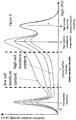
- Fig. 3 the energy density distribution of neutrons related to four different soil moisture contents is illustrated.
- the 4 different lines give an idea about the intensity distribution for 1%, 10%, 20% and 40% relative soil moisture.
- the rightmost peak indicates high energetic atmospheric and cosmic neutrons. This peak is characteristic for neutrons of primary reactions in the atmosphere by extrasolar particles indicated with the reference sign "a" and present in all curves in a high energy region. These neutrons make up a large part of the downward facing incoming radiation.
- Neutrons may also be products/particles of secondary cosmic rays also known as secondary cosmic radiation (inset of Fig. 1 referring to a possible reaction causing cosmic shower).
- Secondary cosmic-ray particles e.g., muons, protons, pions, neutrons
- secondary cosmic-ray particles are generated by electromagnetic and nuclear interactions mostly in the outer part of the Earth's atmosphere.
- cosmic neutrons originate from nuclear reactions with particles at the fringe region of the atmosphere, the reactions caused by stellar or solar particles ("solar winds" for example), such as high-energetic protons as shown in the inset of Fig. 1 or electrons and ⁇ -particles, when entering the atmosphere.
- the entity of particles which are generated in such events is therefore called particle/cosmic shower.
- events also comprise elastic scattering.
- a neutron may for example lose energy by colliding and elastic scattering with atmospheric light particles, particularly hydrogen atoms having similar mass. The more scattering events a neutron has experienced, the less energy it has. This correlates directly with the so-called average free path, a measure for how far a neutron can travel before colliding with a particle in average.
- Cosmic or atmospheric neutrons at very high altitudes did not yet experience many scatter events, still having a high energy and a long average free path length.
- the pressure in high altitudes is very low due to a low atmospheric particle density, the probability for neutrons to collide with a particle is still low.
- the energy regime for fast secondary neutrons is indicated by the reference sign "b".
- This second peak from the right is related to evaporation neutrons. These neutrons are released from interactions of high energetic cosmic particles with other non-hydrogen atoms. They have energies in the range of about one to several MeV.
- the energy distribution spectra ED 2 , ED 1 for high and low altitudes each contain this peak.
- neutrons are efficiently slowed down by elastic collisions, particularly in the range limited by the dashed bars as illustrated in Fig. 3 (1 eV - 0.1 MeV).
- the soil acts as a reflector and generator or moderator of neutrons.
- the process of moderation (slowing down) of fast neutrons is most efficient for collisions with hydrogen.
- a wet body e.g. wet soil or a water surface such as lake
- the slowing down is more efficient needing less collisions to lose energy.
- An efficient range in the spectrum for water-sensitive neutron detection preferably used in connection with the present disclosure is the energy range which is marked with the reference sign "d" and the two dashed bars as indicated in Fig. 3 .
- the energy density distribution ED 1 curve for low altitudes of Fig. 1 indicates a high neutron density of such epithermal neutrons near the ground G (the water sensitive energy range of the ED 1 curve being marked with multiple vertical bars).
- the number of neutrons, which carry an information of the soil condition decreases with height as indicated by the energy density distribution ED 2 curve for high altitudes of Fig. 1 (the water sensitive energy range of the ED 2 curve also being marked with multiple vertical bars).
- a neutron path which ends at the airship (e.g. blimp), is shown by the arrows (p 1 , p 2 , p 3 ) in Fig. 1 .
- the average free path length for epithermal neutrons is between about 50 m to about 200 m.
- this is the most preferred altitude above ground for using the present invention, i.e. most preferably the airship may float in altitudes in this regime, e.g. between about 10 m and about 300 meters.
- the epithermal and fast regime extends downwards to the thermal regime.
- neutrons are not slowed down any further as they have kinetic energies which correspond to the surrounding material and therefore the energy transfer by collisions on average is zero.
- Such neutrons scatter locally until they are absorbed.
- neutrons are 'thermalized' by water after approximately 20 collisions.
- thermal neutrons have a significantly shorter path length and a higher absorption probability than epithermal neutrons, they are not transported over long distances.
- the peak indicated with reference sign "c" in Fig. 3 corresponds to such thermal equilibrated neutrons.
- the same low energy peak is also present in the energy density distribution ED 1 for neutrons at low altitudes.
- the peaks/regions related to fast, epithermal and slow/thermalized neutrons reveal information about the soil moisture content. Due to the sensitivity to moisture content, the energy range related to fast and epithermal neutrons is preferably selected for deriving soil moisture content, particularly the region which is indicated by the two dashed bars in Fig. 3 .
- the peak, related to high energy neutrons does not reveal a sensitivity to soil moisture content as the neutrons' energy is too high and therefore the neutrons' cross section for interaction with water molecules is too small.
- Thermal neutrons are free neutrons having a kinetic energy distribution with a peak at about 0.025 eV (i.e. about 4.0 ⁇ 10-21 J or 2.4 MJ/kg, corresponding to a speed of 2.2 km/s). This energy corresponds to the most probable velocity at a temperature of about 290 K, i.e. about 17 °C or about 62 °F (for the Maxwell-Boltzmann distribution for this temperature).
- thermal neutrons a neutron moderator
- epithermal neutrons arrive at about this energy level, provided that they are not absorbed.
- the energy domain which characterizes thermal neutrons is the region of the spectrum indicated by "thermalized neutrons”.
- thermal neutrons for a given nuclide is different and often much larger than the absorption cross-section of fast neutrons. Therefore, such thermal neutrons can often be absorbed more easily by an atomic nucleus. In this process of absorption, a heavier, often unstable isotope of the chemical element is generated.
- the energy range of epithermal neutrons may be considered to cover a range between about 0.05 eV and about 0.4 eV.
- the energy range of fast neutrons may be considered to cover a range between about 1 MeV and about 20 MeV.
- Neutrons which are particularly indicative of soil water content have energies which are in the water sensitive domain "d" of the spectrum. In this respect, it is referred to the gray square of Fig. 3 as indicated by “epithermal/fast neutrons, water sensitive domain” or “d” (also indicated by the two dashed bars in Fig. 3 ). Particularly the neutrons which are in the energy range between about 1 eV and about 100 keV are most sensitive to soil water content. The scattering cross-sections of the neutrons at such energies allow interaction such as scattering with nuclei in the soil, while absorption is comparatively small.
- the neutrons which are in this particular energy range when reaching the moderator before being slowed down/moderated by the moderator medium to energies of thermal neutrons are the neutrons of specific interest for the present soil water content measurement. It is pronounced, that the neutrons of interest for soil water content determination do have energies in the water sensitive domain (i.e. 1 eV to 100 keV) when reaching the moderator and before interacting with the moderator medium. After the process of moderation, the neutrons have energies which are characteristic for thermal neutrons. The detector 3 is efficiency able to detect such thermal neutrons.
- Neutrons which have energies outside of this water sensitive domain and which are therefore not sensitive to soil water molecules may be considered background neutrons.
- Such background neutrons may for example be fast or high-energy neutrons at energy ranges above 100 keV. In this respect, it is referred to the energy domains indicated by "fast neutron creation by evaporation” and “high energy neutrons (primary cosmic radiation)".
- neutrons which are already thermalized when reaching the airship 2 and which are not sensitive to soil water content are considered background neutrons.
- the background neutrons do not contribute to the determination of soil water content. Therefore the part of the neutron density/energy spectrum generated by background neutrons is required to be subtracted from the measured spectrum in order to extract the part of the spectrum from which the water content can be derived.
- the neutrons in the epithermal energy range are highly sensitive to soil moisture content.
- the neutron detector 3 is specifically configured to detect neutrons which are in this energy range when they approach the airship 2. However, to increase the probability of being detected related to the reaction cross section, those epithermal neutrons are further slowed down/moderated right before entering the detector.
- 10 B-neutron detectors such as Jalousie detectors are used for the present invention
- the reaction/interaction between 10 B and neutron follows most likely the following conversion reaction: B 10 + n ⁇ Li * + ⁇ ⁇ Li 7 7 + ⁇ + ⁇ + 2.31 MeV .
- the detector which is preferably a proportional counter, in fact measures the charges which are generated proportionally with the number of reactions caused by the neutrons.
- a processing unit of a computer 8 may then analyze the measurement and derive a neutron density. As one result an angular dependence of the neutron density is indicative of the soil moisture content, as illustrated as the dashed lines (S 1 , S 2 ) of Fig. 1 .
- the dashed lines therefore show the radial sensitivity of neutrons having epithermal energy.
- the neutron density is measured from the center of the area A at the floating altitude H of the sensor.
- the cases of dry (right dashed line S 1 ) and wet soil (left dashed line S 2 ) are illustrated as radial intensity distributions.
- Fig. 1 illustrates schematically the angle and moisture content dependencies of the neutron density in the signal curves S 1 , S 2 .
- the soil contains high moisture content - as indicated by curve S 2 - less neutrons are reflected from the earth's surface towards the airship as more scattering between water molecules and neutrons takes place.
- the neutron energy is an indirectly measured quantity.
- the neutron counter according to the invention counts thermal neutrons.
- the moderator slows down neutrons to thermal energies, which is a statistical process.
- the kinetic energy before entering the device (1) can only be estimated by means of ensemble statistics.
- Fig. 4 a more detailed diagram illustrates the dependence between the detected neutron density/radial sensitivity (y-axis) and radial surface distance from the detector (x-axis) and floating altitude/height above ground (dotted, dashed, dash-dotted, solid lines). Curves for four different altitudes, i.e. 10, 50, 100 and 190 m above ground G are plotted (dotted, dashed, dash-dotted and solid, respectively), against the radial surface distance R from the detector 3, as already indicated in Fig. 1 with reference sign "R". All curves refer to a soil moisture content of 10 %.
- each curve peaks at a certain radial distance R.
- the according maxima occur at short distances R for low altitudes H.
- the curves related to a floating altitude H of 50 m reveal a maximum neutron density for a radial distance R between source and position over ground G of the airship of approximately 25 m as opposed to 80-90 m for the curves related to the altitude H of 190 m.
- radial surface distances R from the detector 3, at which 86 % of the overall neutron counting rate is measured is illustrated as vertical lines for the first three altitudes H.
- the distance R is approximately 213 m (dotted vertical line) for an altitude H of 10 m.
- the distance R is 254 m (dashed vertical line) for an altitude H of 50 m and 299 m (dash-dotted vertical line) for an altitude H of 100 m.
- the size of the area to be scanned it can be calculated what the optimum altitude H would be. If an operator does not desire to achieve a high spatial resolution but a large area needs to be scanned, it is advantageous to select an altitude H which is high, such as heights H between 150 and 300 m. If a small area A needs to be scanned at a high spatial resolution, it is required to select a low altitude H, such as 10 to 100 m.
- the calibration may be automated and performed by a machine or it may be done "by hand".
- the values may be entered into a program automatically or the data may be entered into a program "by hand”.
- the calibration program may be stored on a machine/computer which is carried by the airship or the calibration program may be stored on a machine/computer which is on the ground, possibly implemented in a base station.
- the secondary data which might be measured at the airship may be transmitted to a machine and/or remote control on the ground for calibration and/or recording.
- Fig. 5 is a cut/cross section of the moisture measurement apparatus 1 between the points q and q', as indicated in Fig. 2 .
- the drawing schematically illustrates how a neutron on its path is slowed down by the moderator in the moderator gas-filled volume V of the airship 2.
- the neutron of interest has an average free path length p 3 (see also Fig. 1 ) when approaching and entering the volume V of the airship 2 related to an energy, which is in the range of epithermal neutrons (as already discussed in relation with Fig. 3 ).
- the moderator particles which may be also used as the carrier gas in the airship 2
- the neutrons are slowed down to lower energies.
- the detector medium is 10 B, related to a preferred embodiment.
- the average free path length - as indicated as an example by the length of the arrows of p 4 and p 5 - becomes shorter before entering the neutron detector 3.
- the position of the detector 3 as indicated as a solid box in Fig. 5 is preferably centered with respect to the volume V of the airship 2.
- the detector 3 may have a position which is different from the center, as indicated by the dashed boxes.
- the detector 3 may then be more selective to neutrons with a certain incoming direction, as the neutrons coming in from one side may not be slowed down to the same extend as the neutrons coming in from another side.
Landscapes
- Life Sciences & Earth Sciences (AREA)
- Chemical & Material Sciences (AREA)
- Health & Medical Sciences (AREA)
- Analytical Chemistry (AREA)
- Engineering & Computer Science (AREA)
- Pathology (AREA)
- Immunology (AREA)
- General Physics & Mathematics (AREA)
- General Health & Medical Sciences (AREA)
- Biochemistry (AREA)
- Physics & Mathematics (AREA)
- Geology (AREA)
- Medicinal Chemistry (AREA)
- Food Science & Technology (AREA)
- Remote Sensing (AREA)
- General Life Sciences & Earth Sciences (AREA)
- Environmental & Geological Engineering (AREA)
- Crystallography & Structural Chemistry (AREA)
- Analysing Materials By The Use Of Radiation (AREA)
Abstract
Description
- The present invention relates to a moisture measurement apparatus, particularly a soil moisture measurement apparatus and a related method based on cosmic ray neutron probing (CRNP) and particularly based on cosmic ray induced atmospheric neutron probing. In this respect, it is also simply referred to neutrons and neutron probing or neutron sensing in the present application.
- In recent years, ecological disasters have increased tremendously in numbers and damage. Flooding and possible landslip related to flooding are some of the phenomena causing enormous damage and endangering human lives in multiple regions and countries of the earth. Predicting the probability and an acute risk of flooding is therefore essential for limiting damage, evacuation and saving lives. However, a reliable prediction is object of ongoing research and still remains challenging.
- One important parameter for predicting phenomena related to flooding is the moisture/water content of soil and the degree of soil water saturation. Thus, determining soil moisture content plays an essential role in disaster predictions, environmental monitoring, and hydrological applications.
- Another field which requires the reliable determination of soil moisture content may be farming, particularly sustainable and precision farming. It is important for a farmer to know exact amounts of moisture contained in the soil for determining the correct/optimal amount of irrigation, for example. This may help to achieve optimal growing results, to avoid salting of the soil, to avoid flooding and to safe water which is particularly important in dry areas.
- In this respect, it is preferable to provide an eco-friendly, simple and reliable technique for non-invasively measuring the soil moisture of large land areas. Such areas may possibly be located in impassable and rough terrain. In view of these factors, multiple techniques have been developed for measuring the water/moisture content in soil.
- To date, soil moisture content has been determined by means of local contact-based (invasive) techniques. One such technique is based on weighing a portion of soil including soil moisture content, weighing the same portion of soil after heating and evaporating the moisture content. The moisture content is then determined by subtracting the measured weights from each other. Alternatively, soil moisture content may be determined by measuring the electrical resistance while applying an electrical field to a portion of soil. Other methods for detecting soil moisture content include time domain - or frequency domain reflectometry, which requires injecting a wire into a portion of soil. Further, a Troxler detection head has been used to introduce neutrons locally into a portion of soil and to measure thermalization. These well-established methods have been known and applied for decades. They are contact-based and allow for distinct local probing. Further, most of these methods - being invasive - require insertion into the soil or permanent positioning below the soil.
- The soil water content may also be estimated by means of satellite based systems detecting radio or optical signals. This allows to roughly scan large areas in view of hydrologic applications, as the altitude of satellites is extremely large compared to other systems.
- A technique which has recently been developed and is still object of ongoing research is based on a signal to noise ratio (SNR) recorded by high precision GPS receivers, wherein such receivers are already in place for geodetic applications. Some of the noise in a GPS signal comes from reflections of the GPS signal off of the ground. These reflected signals come in and out of phase with the direct signal as a GPS satellite rises, and as a result, the recorded SNR data rise and fall over this some time period, creating a sine curve. The shape of this SNR sine curve changes depending on the amount of water in the soil.
- An alternative non-invasive technique for measuring soil water content in the range of several square kilometers, related to weather observation, is based on optical spectral detection of the Earth's surface with satellites, known as remote sensing. Areas under clouds can hardly be probed using satellite based soil moisture content detection. The first centimeter of the soil may be probed with this method. Vertical inhomogeneity of soil moisture content further requires careful analysis of measured data using precise soil models.
- Cosmic ray neutron sensing or cosmic ray neutron probing (CRNP) - another non-invasive contactless technique to identify soil moisture content - has recently been introduced for the first time (in 2008). This method is based on the detection of neutron density related to such neutrons which have been reflected/scattered back from the soil. These neutrons are particularly sensitive to and indicative of soil moisture content. Such neutrons are cosmic ray induced atmospheric neutrons. The origin of these neutrons is discussed in more detail further below.
- To date, thermal neutron detectors have been applied for this technique (mainly produced by the company Hydroinnova). Such detectors can be installed at fixed positions or transported in a vehicle to provide a degree of mobility. Other means for providing a high degree of mobility have been reported, such as gyrocopters or microlights. Therefore, the benefits of transporting the detector at a high altitude during detection, such as probing a large area, can be exploited.
- However, it still remains challenging to provide a technology which allows for reliably scanning and/or imaging soil moisture content in large areas at realistic costs.
- According to an aspect, it is a problem to determine the soil moisture content of large areas with an improved degree of reliability. The problem is solved by an apparatus and a method having the features defined in the independent claims. Preferred embodiments are covered by the dependent claims.
- The present invention relates to an apparatus and a respective method for probing moisture content and more particularly soil moisture content by means of detecting neutrons. The spatial range which may be covered by the invention (including the size of the observable area of typically multiple hectares and the special resolution) lies in a regime which has so far been challenging to be covered by means of conventional probing techniques. In particular, the size of the observable area is larger than for typical conventional local detecting systems. On the other hand, the spatial resolution achieved by the present disclosure is higher than for typical conventional satellite based detection systems.
- Therefore, the apparatus and method according to the present disclosure may be applied for passive mobile large scale hydrological measurements, particularly for flood control and prevention and for farming and particularly for precision farming. The field of the present disclosure is however not limited to said application and may be extended to other meteorological and/or biological fields such as weather observation, observation of cloud and/or fog/mist development and/or water accumulation and/or vegetal cover and/or snow cover as well as the condition of snow fields.
- According to the present invention a moisture measurement apparatus is provided for detecting moisture content, particularly soil moisture content. The apparatus comprising:
- an airship configured to float over an observation area of the earth's surface;
- a neutron moderator carried by the airship and configured to slow down neutrons scattered and/or reflected at the observation area of the earth's surface;
- a neutron detector at least partly surrounded by the neutron moderator and configured to detect a neutron density; and
- an evaluation module configured to determine the moisture content from the detected neutron density.
- Airships and related "lighter-than-air technologies" have long been known to provide multiple advantages, such as being eco-friendly and cheap due to low energy consumption, low noise production, ability to transport heavy loads from point to point, ability to move far distances while being flexible in reaching various altitudes and being mobile over impassable and rough terrain. Further, as opposed to aerodynes, such as planes, helicopters, gyrocopters or drones, airships are able to move/float over land at very low pace up to standing still with respect to the geological coordinate. Further, airships are not required to be started from a starting-/landing strip. The restrictions regarding the starting and/or landing positions of airships are low, in general. Further, depending on the carrier gas used in the airship, the risk for accidents can be held very low.
- For the above reasons, it is also preferable to provide an airship for neutron sensing. All said advantages related to airships can thus be exploited in conjunction with determining soil moisture content.
- It is particularly beneficial to provide an airship for neutron sensing as it may float at altitudes which allow probing large surface areas and large spatial coverage. Such areas may possibly be located in impassable and rough terrain. This is of particular interest as the risk of landslip due to high soil water content is usually high at mountains and in mountainous countryside which is often rough and hard to approach. It is beneficial in view of versatility to use a technique for scanning large areas (i.e. several hectares and more) rather than using a technique which allows for local measurements for evaluating and observing the hydrological condition as well as the degree of saturation of soil water in a vast landscape. For example, an observation area of about one to ten hectares may be probed quickly and precisely using the apparatus according to the present invention. Moreover, a scanned observation area may also be larger. Alternatively, the observation area to be scanned and probed may also be smaller, particularly in the case when the airship is fixed and/or tethered to a fixed position over the ground. As opposed to conventional local, static detection systems, the present invention allows scanning larger areas. On the other hand, as opposed to conventional satellite based systems, the present invention provides a more reliable detection with a higher spatial resolution. Further, mobile neutron sensing according to the present disclosure does not require a large-scale network of sensors at fixed positions, hence being less extensive and expensive in view of installation and maintenance. Mobile neutron sensing according to the present disclosure also allows a user to apply the technique wherever needed acutely. At the same time, the present disclosure also allows to take into account soil moisture content present in several decimeters below the earth's surface, thus providing a more reliable conclusion about the soil's saturation with water.
- As an airship can float at very low floating pace, multiple measurements may be recorded for one area as the airship moves over small distances, thus being considered quasi-static in a rough approximation. The temporal window for reliably detecting soil moisture content of a particular area, being determined by the floating pace, is therefore improved. This gives rise to improved accuracy, improved spatial resolution and as a result a higher degree of reliability. Further, neutron sensing is a non-invasive, sensitive as well as reliable technique for probing soil moisture content. Therefore, the apparatus and related method according to the present invention can improve efficiency and reliability when implemented in an early-warning system.
- According to an embodiment, the at least one airship is at least partially filled with a carrier gas when floating. In a non-filled state, i.e. when the gas-filled volume of the airship is compressed and not filled with a gas, the airship may easily be transported as the volume is reduced down to small sizes. When the volume is at least partially filled with a carrier gas, the airship can adopt at least in parts its full size. In this case, the airship uses the buoyancy force for floating as the carrier gas is lighter than air. As opposed to other aircrafts, such as helicopters or gyrocopters, a gas-filled airship can exploit the buoyancy force at very high altitudes.
- According to an embodiment, the carrier gas at least partially serves as the at least one moderator medium. In view of efficiency, it is beneficial to fill the volume of the airship with a gas which is used at least in parts as a carrier medium and as a moderator medium (i.e. for slowing down the neutrons before detection) at the same time. In the process of moderation, fast neutrons are slowed down to kinetic energies at which they can effectively be detected by the neutron detector. Often, the neutron detectors which are used for neutron sensing comprise a solid state moderator medium, such as polyethylene. A polyethylene moderator medium can weigh as much as 8 to 30 kg. Therefore the additional weight may be reduced or completely avoided if the carrier gas has a moderating function. If a small aircraft is to be used for neutron sensing, such weights to be carried would limit or render the measurement impossible. Favorably, the airship may simply carry the thermal neutron detector's weight and its own weight, as the carrier gas is lighter than air and does have the functions of carrying the apparatus and moderating the neutrons at the same time. Therefore, an efficient apparatus can be provided having a large detection volume, floating slowly at low altitudes and simply carrying the weight of the sensor if no additional equipment is to be carried. Energy consumption and costs may therefore be reduced.
- According to an embodiment, the carrier gas is at least partially one out of hydrogen, helium, heated air, methane, ammonia, neon, acetylene, diborane, carbon monoxide, nitrogen and ethene or a mixture thereof. A carrier gas which contains hydrogen atoms, such as hydrogen or methane, is efficient in moderating neutrons. Making use of such compounds is therefore beneficial, as they serve efficiently as the carrier gas and the moderator medium at the same time. Further, it is beneficial in some cases to use for example hydrogen gas instead of helium gas as a carrier gas, as hydrogen is more efficient in its buoyancy properties and less expensive. For safety reasons it may however also be favorable to provide helium gas instead of hydrogen gas, as it is inert and not explosive. Excluding for example mixtures of gases such as oxyhydrogen gases which would cause combustion, it might also be beneficial to provide other said gases or mixtures of said gases in order to tune moderator and/or carrying features. Separate gas chambers may therefore be provided to isolate different gases in the volume of the airship.
- According to an embodiment, the at least one neutron detector is at least partially surrounded by the carrier gas. If the neutron detector is at least partially surrounded by the carrier gas, the neutrons can be slowed down in the vicinity of the detector, particularly if the carrier gas is also used as the moderator medium. The gas phase which at least partially surrounds the detector may then substitute a moderator shell such as a polyethylene case or cover.
- According to an embodiment, the at least one neutron detector comprises at least one gas proportional detector, particularly a boron neutron converter and more particularly a Jalousie detector and/or a scintillation neutron detector and/or a semiconductor neutron detector.
- As opposed to 3He neutron detectors, boron neutron converters (10B solid state detector), such as Jalousie detectors, are far less expensive. Therefore, a probing interval can be substantially extended to long duration. Large areas of landscape may therefore be probed with boron neutron converters. On the contrary, 3He is expensive and as a result only small amounts of 3He may be provided in a detector such that only small areas of landscapes can be probed. With boron detectors however, soil moisture content of a larger area and at a higher spatial resolution can be achieved during a typical probing interval of one day. It can also be beneficial to provide multiple detectors in view of expanding the probing intervals or further improving reliability. It cannot be excluded that, in some cases, it is beneficial to provide detectors based on other technologies (in addition or as an alternative to boron neutron converters), particularly if such detectors are cheaper and/or more reliable and/or having a longer life time.
- According to an embodiment, the apparatus further comprises at least one:
- second measurement device configured to detect at least one out of humidity, pressure, background radiation, background neutron density, floating altitude, temperature, time lapse, weight of a carried object, carrier gas volume and/or carrier gas pressure, geomorphology and/or natural vegetal cover within the observation area of the earth's surface; and/or
- camera configured for imaging the geographic landscape.
- Recording other measures which do not involve neutron energy (as a derivative), such as the above mentioned ones, is favorable as conditions can be recorded and measures which may help deriving the soil moisture content from the neutron density and the energy distribution can be detected. Such measures, as for example barometric pressure or temperature may be useful for the calibration of the neutron detector. However, such values can also be recorded independently from the neutron detection from additional meteorological observations. A manifold of parameters can be detected and fed into a model for weather prediction, severe weather prediction and/or ecological disasters prediction related to weather phenomena.
- According to an embodiment, conditions and/or features and/or functions of the apparatus, such as float velocity, position, floating altitude, carrier gas pressure and/or detection of measures are controlled dynamically and/or in a predetermined manner by means of at least one control element out of a remote control, a computer, a smartphone, a satellite, or a base station and/or data may be exchanged between the control element and the apparatus.
- An operator may dynamically derive a condition of the soil and/or weather from the detected data when the data is exchanged between (elements of) the apparatus and control elements on the ground, such as a remote control and/or a computer/server. In other words, it may be advantageous to transfer data between detection elements and computers and/or servers, e.g. via mobile Internet, for instantaneous storage and/or analysis of the exchanged data. It is also possible that communication takes place between several control elements and the airship via a receiver or transceiver at the apparatus or airship. For example, a GPS signal of satellites may be received by a receiver in the airship, the receiver may be connected to a computer either in/at the airship or on the ground such that the computer can derive the exact position and floating velocity. Based on such data, an operator can control the floating trajectory and/or pace of the airship.
- According to another aspect, the present invention provides a method of detecting moisture content and particularly soil moisture content comprising the steps of:
- providing at least one airship filled with a carrier gas, the airship floating over an observation area of the earth's surface;
- carrying at least one neutron detector with the at least one airship, such that the neutron detector is at least partly surrounded by a moderator medium;
- detecting a neutron density by means of the detector; and
- determining the moisture content from the detected neutron density.
- According to an embodiment neutrons are at least partly moderated by means of the carrier gas. According to yet another embodiment, the neutron detector may be a gas proportional detector, particularly a boron neutron converter and more particularly a Jalousie detector and/or a scintillation neutron detector and/or a semiconductor neutron detector. According to yet another embodiment, the at least one neutron detector may be positioned substantially inside a gas filled volume of the airship. According to yet another embodiment, the method may comprise:
- detecting at least one out of humidity, pressure, background radiation, background neutron density, floating altitude, temperature, time lapse, weight of a carried object, carrier gas volume and/or carrier gas pressure, geomorphology and/or natural vegetal cover of the below area; and/or
- imaging the geographic landscape.
- According to yet another embodiment, the method may comprise:
- controlling dynamically and/or in a predetermined manner conditions and/or features and/or functions of the apparatus, such as floating velocity, position, floating altitude, carrier gas pressure and/or detection of measures by means of at least one control element out of a remote control, a computer, a smartphone, a satellite, or a base station; and/or
- exchanging data between the control element and the apparatus.
- According to yet another embodiment, the method may comprise:
- floating in an altitude between about 5 and about 200 m above ground; and
- screening the observation area of the earth's surface by means of floating in predetermined floating directions; or
- positioning the airship at fixed geographic coordinates; and/or
- fixing the airship to at least one reference point on the ground by at least one physical means, particularly a rope.
- A preferential altitude between 5 and 200 m allows screening a large area compared to areas probed with conventional techniques. Floating however at a low altitude - around 5 to 10 and up to 50 m - allows probing the soil moisture content locally with higher precision and improved spatial resolution. If larger areas are to be screened, possibly in rough terrain and/or above a city or a forest, the airship may float at higher altitudes, for example at altitudes of 100 to 300 m. Depending on the requirements, the airship can float at different altitudes. Therefore, the method of detecting soil moisture content in the said altitude range allows versatile applications for different requirements or limitations due to the landscape or the operator's desires.
- A dynamic control of the airship's position is favorable if an operator does not want to predetermine a trajectory. However, pre-setting a trajectory of the airship may be beneficial as automated aviation requires less man power and a remote control/computer autonomously controls the position and the pace of the airship. This may include that the airship can be operated as a drone.
- The airship may be fixed to a position with respect to the geographic coordinate if the development/change of a condition at a certain position/small area (instead of a large area) over a longer time span is required to be probed. A fixed position of the airship can be achieved by dynamically controlling and possibly correcting for drift due to wind or by tethering the airship by means of at least one rope to a fixed position on the ground. The rope may not only be used to fix the airship but also to move it in a controlled manner to a new position, if required. In such cases, the airship may also be a balloon. However, it may be beneficial in terms of versatility to have the option of either fixing the airship to a certain position or moving it over the preferred or predetermined landscape using either a rope and/or a remote control operated my an operator and/or a machine.
- As the moisture measurement apparatus can be cost-effective, reliable, versatile, efficient, and handled in a straightforward manner, it may particularly be used in rough terrain, areas which often suffer ecological disasters and particular less developed countries which suffer poverty and a low degree of infrastructure. Such countries often experience ecological disasters related to flooding and landslip causing death of humans, animal stock and/or loss of property. Further, the moisture measurement apparatus may be applied by farmers to estimate the soil moisture content and to derive efficient/optimal amounts of irrigation. Again, less developed countries, often suffering water scarcity, may benefit in particular from the moisture measurement apparatus. The moisture measurement apparatus may therefore be configured to be used by either a private person, such as a farmer or a professional operator, such as a meteorologist or a person on behalf of the government or a company. The training for becoming an operator of the moisture measurement apparatus may therefore be simple depending on the requirements.
- Further embodiments, aspects/features, advantages and functions are described in more detail as follows. It is self-evident, that features which do not contradict each other can be assumed combinable and therefore the below examples are not restricted to particular embodiments.
- Fig. 1
- is a schematic drawing for demonstrating the function of the moisture measurement apparatus;
- Fig. 2
- is a detailed schematic drawing of the moisture measurement apparatus;
- Fig. 3
- is a diagram showing an energy distribution for neutrons measured in the atmosphere over soil with different soil moisture content;
- Fig. 4
- is a diagram showing the radial sensitivity of neutrons detected at four different altitudes over soil with either high or low soil moisture content;
- Fig. 5
- is a cut/cross section between the lines q and q' of the moisture measurement apparatus of
Figure 2 . -
Fig. 1 ,Fig. 2 andFig. 5 show a spatial three dimensional coordinate system, wherein the orthogonal directions are indicated by arrows related to the reference signs x, y, z. In this representation x and y refer to a horizontal plane or a surface at one particular altitude, i.e. for example a flat ground G, neglecting the earth's curvature in an approximation. z on the other hand, indicates the vertical direction. The arrow for the vertical direction z is directed "upwards", i.e. towards higher altitudes. In other words, the arrow is directed from the ground G of the earth towards the sky/top of the atmosphere. -
Fig. 1 schematically illustrates one embodiment of the invention, also containing features which are not essential for the invention. Such additional features may be indicated as being optional. In other words, some aspects - particularly the aspects related the dependent claims - as illustrated in the figures may not limit the scope of the invention, as such aspects are not required for realizing the invention according to the independent claim. - Referring to
Fig. 1 andFig. 2 , anapparatus 1 for probing soil moisture content by means of detecting neutrons is described in the following. It is self-evident that a method for probing soil moisture content by means of detecting neutrons is covered by the same description. When referring to neutrons, mostly cosmic ray induced atmospheric neutrons are regarded. However, also cosmic neutrons may be detected and should therefore be covered by the term. Themoisture measurement apparatus 1 according to the present invention is configured to detect moisture content, preferably soil moisture content. Alternatively or additionally, it may be possible to also detect moisture content related to biological cover (grass, trees, bushes or forest), fog, mist, clouds, snow fields and other possible phenomena related to moisture and/or presence of water. - The
moisture measurement apparatus 1 according to the present invention comprises at least oneairship 2 and at least oneneutron detector 3, which is preferably positioned inside the airship as indicated inFig. 1 andFig. 2 . Theneutron detector 3 is configured to detect particularly thermal neutrons. These thermal neutrons may result from slowing down faster neutrons to energies which can be efficiently detected by theneutron detector 3, as will be described in more detail below. Thedetector 3 can either be a gaseous hybrid detector with solid neutron converters like 10B or a gaseous detector with 3He for example. Preferably, thedetector 3 comprises several layers of boron carbide coatings on a cathode, Argon-CO2 as a counting gas and a wire based anode, which is based on the principle of a proportional tube or a multi wire proportional chamber. - In more detail, the
neutron detector 3 is described with respect toFig. 1 andFig. 2 which illustrate theapparatus 1 comprising oneneutron detector 3. Alternatively, particularly for long term measurements a plurality ofneutron detectors 3 may be provided. Preferably, theneutron detector 3 may comprise a gas proportional detector. More preferably, theneutron detector 3 may comprise a boron (10B) neutron converter, particularly a Jalousie detector. As opposed to 3He-detectors, which are often used for neutron detection, as they are compact and efficient, the boron neutron detectors are less expensive. 3He is so expensive (1500 $/I) that only small amounts/volumes can be provided for use inneutron detectors 3 such that only long probing intervals limited by the count rate (typically 1 hour) are affordable. 10B-solid state detectors are much cheaper. Therefore, larger detection volumes can be used resulting in higher neutron count rates and short probing intervals (typically a few minutes) can be realized for a typical accuracy which scales with the square root of the counted neutrons. In other words, using a preferred 10B-based neutron detector such as a Jalousie detector, a large area may be scanned, as the time required for the measurement at a single point at the surface of the landscape may be much shorter as opposed to the case in which 3He-detectors are used. Further, if theairship 2 floats at very slow pace, a high spatial resolution and/or a high degree of reliability may be achieved as the time for averaging the measured data over a certain area is long. The preferred 10B detector comprises a wire chamber and boron carbide converters being specifically designed to fit the geometry of theairship 2, which is a blimp inFig. 1 andFig. 2 . Preferably theneutron detector 3 is a 10B-based detector and more preferably a so-called Jalousie detector. - However, it may also be possible in alternative embodiments that a 3He-detector is provided alone or in addition to some other neutron detector(s). The
neutron detector 3 may also comprise a scintillation neutron detector and/or a semiconductor neutron detector as an alternative or in addition to other neutron detector(s). - In any case, it is preferred to apply a neutron detector which is specifically (or most) sensitive to thermal neutrons, i.e. neutron with a kinetic energy of about 25 meV, or an energy in the range of up to about 0.05 eV. Such neutron detectors are widely available and relatively easy to handle and to maintain. Moreover, when using such a detector in combination with a moderator according to the present disclosure, it turned out that a neutron density of thermal neutrons detected by the detector can be used as a reliable measure of soil moisture content, as will be described in more detail further below.
- As already mentioned, the
moisture measurement apparatus 1 comprises at least oneairship 2, preferably theapparatus 1 comprises oneairship 2 as illustrated inFig. 1 . Theairship 2 may also be known as or comprise a dirigible or aerostat. Theterm airship 2 may comprise non-rigid (e.g. blimps, balloons such as tethered or moored balloons, and free-floating balloons etc.) or semi-rigid airships. Even though theairship 2 may also be a rigid airship (e.g. Zeppelins), it is preferred that themoisture measurement apparatus 1 comprises anairship 2 having a non-rigid structure. Anairship 2 with a non-rigid structure can be folded and packed when its volume V is not yet filled with gas, e.g. before operation. - The weight of an
airship 2 is mainly due to its hull. However, the weight may also be substantially determined by the weight of the fuel, which may be high for long distance flights and/or windy conditions. It may be preferential to choose aheavier airship 2 if operating under rough conditions, such as strong winds, as aheavier airship 2 tends to be more stable against changes of wind directions. The overall weight of an accordingmeasurement apparatus 1 may be up to 1000 kg. Preferably, the weight of themeasurement apparatus 1 comprising theairship 2 is however low, particularly around 100 kg. Therefore, that transportation can be simplified. In other words such anairship 2 according to the preferred embodiment has a low weight and can adopt a very small volume V when it is not in an operational mode, for example when it is sold or sent to a customer or transported to the preferred destination where it should be operated. - Preferably, the
airship 2 is a blimp and adopts a length L between 1 and 20 m, when in the operating configuration, i.e. for example when being filled with the carrier gas and/or ready to float. More preferably, the length L of theairship 2 is approximately 10 m. Preferably, theairship 2 is configured to be remote controlled by an operator and/or a machine via wireless connection to aremote control 6 and/orcomputer 8 and/or other control element. Preferably, theairship 2 is configured to float in a floating direction FD in order to scan and probe a certain area on the ground G. In the preferred embodiment theairship 2 is configured to be remote controlled via wireless connection. In another preferred embodiment theairship 2 is configured to be remote controlled via wireless connection and by means or a rope. Theairship 2 may float using an engine which is positioned at the airship as illustrated inFig. 1 . Alternatively or additionally, theairship 2 may be driven externally via a rope which is either guided by an operator by hand and/or by an engine on the ground G. Theairship 2 may also be tethered to a fixed position on the ground G. Preferably theairship 2 is configured to float in a floating direction FD and to be located at a fixed position, e.g. by means of a rope which tethers theairship 2 to the ground G. - Alternatively, the airship may also have a rigid structure, may also be heavier than 100 or even heavier than 1000 kg and/or may not be foldable into a compact shape. Therefore, the
airship 2 may adopt a length L either smaller than 1 meter, for example if theairship 2 comprises a balloon, or longer than 20 meters if theairship 2 comprises a Zeppelin. It may be necessary in an optional embodiment that the Volume V is at least partially maintained particularly if theairship 2 has a semi-rigid or rigid structure. However, such anairship 2 in a non-operational state may be filled with a non-carrier gas such as air. - Preferably, the
airship 2 floats at altitudes H between about 5 m and about 300 m, more preferably between about 20 m and about 200 m and even more preferably between about 50 m and about 150 m. The upper limit of the altitude H is thereby mainly limited by the average free path length of neutrons being reflected from the soil, wherein the average free path length is related to the signal strength, i.e. a measure related to the neutron density/count rate. The average free path length is a measure for the average distance for a particle needed to interact with another particle. InFig. 1 , the average free path length is schematically illustrated using the reference signs p1, p2, p3. As schematically indicated by the length of the arrows, the average free path length decreases with rising altitude H, as the number of scatter events rises causing a loss of neutron energy. This process is described below in more detail with respect toFig. 3 and particularlyFig. 4 . It is hence required to adjust or optimize the altitude H for a large enough probing area A and a strong enough neutron counting signal in view of the said trade-off. Alternatively, theairship 2 may be configured to float at altitudes H higher than about 300 m. - Preferably, the
airship 2 floats at a slow pace over ground G between about 0 and about 50 km/h, even more preferably between about 0 and about 20 km/h. The time/period required for detection of one measurement point (typically in the range of minutes) and of a typical favorable area (typically several hectares) at a high enough spatial resolution and reliability corresponds well to the said floating pace. Alternatively, motors may be provided which allow alarge airship 2 to float at a pace up to -about 125 km/h. However, light airships typically do not exceed a pace of 50 km/h. Floating at such high pace or even faster is however not preferred, as the measurements suffer loss in reliability and spatial resolution. Therefore, it is favorable and advantageous to provide an airship which is able to float at very slow pace as opposed to other aircrafts, such as gyrocopters, helicopters or small air planes. Preferably, the pace is derived from the preferred duration needed for the measurement, the size of the area to be scanned, the preferred spatial resolution and the desired reliability to be achieved. - At least parts of the volume V of the airship 2 - when in an operating state and floating or ready for floating - are filled with a carrier gas. Preferably, the carrier gas contains elemental or molecular hydrogen atoms and more preferably the carrier gas comprises hydrogen and/or methane. Alternatively, the carrier gas may be one or more out of other gases which are lighter than air, such as helium, heated air, ammonia, neon, acetylene, diborane, carbon monoxide, nitrogen and ethene.
- The carrier gas which is provided in the volume V of the
airship 2 preferably also acts at least in parts as a moderator medium for slowing down neutrons. It is required to slow down fast neutrons, as the cross section for the conversion reaction, required to detect neutrons, increases inverse-proportionally with respect to the decreasing speed of the neutron. To efficiently detect neutrons, a high detection rate (reactivity between neutrons and detector material of the neutron detector 3) is necessary, which calls for slow neutrons. Therefore efficiently moderating the neutrons is required to enable a high detection rate. It is preferred to at least partially provide elemental or molecular hydrogen atoms as moderator, as the hydrogen nucleus, the proton, is most efficient in moderating neutrons due to its equal/similar mass. Most preferably, in view of efficiency, hydrogen is used as a moderator medium - also with respect to the carrying properties and the prize. Another preferable gas to be used as a carrier medium and a moderator medium is methane. - Alternatively, heated air (possibly with water content or hydrogen content) may also be used at least as a carrier gas and possibly as a moderator medium. In another alternative, chambers are provided which separate gas portions inside the volume V of the
airship 2 from each other. Theneutron detector 3 may then be positioned in a chamber filled with a gas acting as a moderator medium and other chambers may comprise different gas which may have good carrying properties. - The
neutron detector 3 is preferably positioned inside theairship 2 such that theneutron detector 3 is surrounded by the gas acting as the moderator medium. As illustrated in more detail inFig. 2 andFig. 5 , theneutron detector 3 is substantially positioned in the center of the volume V of theairship 2. In this preferable configuration, theneutron detector 3 is substantially surrounded by the carrier gas. Alternatively, theneutron detector 3 may also be positioned substantially in the bottom or in the upper, in the front or in the back portion of the volume V of theairship 2. In case, a polyethylene moderator medium is used, theneutron detector 3 may alternatively be positioned at and/or on the outside of theairship 2. In other words, alternatively, theneutron detector 3 may not completely or not at all be surrounded by a gas acting as a moderator medium. It may also be possible in an alternative embodiment that theneutron detector 3 is hanging down from theairship 2. - As indicated in
Fig. 1 andFig. 2 , themoisture measurement apparatus 1 also comprises asecondary detector 5 to probe secondary measures which are not necessarily related directly to neutron sensing. Alternatively, more than one of suchsecondary detectors 5 may be provided at theairship 2, however according to the invention asecondary detector 5 is not explicitly required to realize the invention. As illustrated inFig. 1 andFig. 2 , thesecondary detector 5 is positioned on the outside of theairship 2. Alternatively, one or moresecondary detectors 5 may also be positioned on the inside or theairship 2 or hanging down from theairship 2. One or moresecondary detectors 5 may record measures such as humidity, barometric pressure, temperature, time and/or time lapse, background radiation, particularly background neutron density, floating pace and height/altitude H, position above ground G, weight of carried object, carrier gas volume/pressure, geomorphology and/or natural vegetation which covers the probed below area. Instead of or in addition to asecondary detector 5, a camera may be provided for imaging the geographical landscape such that measured values can be correlated to the particular position above ground at which the values have been detected. The camera may be a digital camera and/or a night-vision device. - The values/data obtained by means of secondary detector(s) and/or camera may serve to gain a more complete picture of the soil condition and/or the weather. For example, if a prediction or a warning system needs to be established, such values may be fed into a forecast model to derive and predict possible future conditions and probabilities. Further, the measured values may be of importance for the calibration of the neutron detection. For example, in order isolate the signal/count rate related to soil water sensitive neutrons from the signal/count rate generated by the background radiation which is not sensitive to soil water content, a spectrum or signal/count rate over a local water source (e.g. a sea) may be recorded and subtracted from the spectrum or signal/count rate recorded over the observation area.
- Further, barometric pressure and humidity may have an influence on the neutrons energy, as more or less scatter events may take place before being detected. Such variations and sensitivities altering the measurement may be derived based on these values. By calibrating the measurement such effects can be excluded/subtracted/isolated from the measured signal to isolate the information which is indicative of soil moisture content only.
- Background radiation and background neutron density may refer to radiation and neutron density, respectively, excluding the neutron density of neutrons which have been scattered by and/or interacted with soil water molecules. In other words, the signal/density value which is measured at the detector and which originates from background radiation and background neutrons does not originate from neutrons which are sensitive to soil water, as they have not been scattered from and interacted with soil water molecules. Therefore, such background data which are included in the measured spectrum are not indicative of soil water content and are therefore preferably subtracted from the measured spectrum or measurement rate/intensity.
- As indicated in
Fig. 1 andFig. 2 , themoisture measurement apparatus 1 also comprises a receiver and/or transmitter/transceiver 4 for communication with control elements (remote control and/ormobile phone 6, server 7,computer 8, and satellite 9) afar from themeasurement apparatus 1. Alternatively, more than one ofsuch transceivers 4 may be provided at theairship 2, however according to the invention atransceiver 4 is not explicitly required. As illustrated inFig. 1 andFig. 2 , thetransceiver 4 is positioned on the outside of theairship 2. Alternatively, one ormore transceivers 4 may also be positioned on the inside or theairship 2 or hanging down from theairship 2. Thetransceiver 4 may be used to receive instructions which would for example be required if theairship 2 was remote controlled. For example, an operator or a machine at the ground G may - viaremote control 6 and/ormobile phone 6 and/or computer 8 - control the trajectory of theairship 2. This may be performed in a predetermined or dynamic manner. Thetransceiver 4 can also receive GPS signals fromsatellites 9 to determine the exact position with respect to the ground G. The position and/or floating pace may either be identified by acomputer 8 on the ground G or by a computer in the GPS receiver, which may transmit the position to an operator or a machine on the ground G. It may also be possible that data are exchanged betweentransceiver 4 and control element on the ground G. For example, the data detected by theneutron detector 3 or the optional secondary detector(s) 5 may be instantly transmitted to acomputer 8 and/or server 7 for storage and/or analysis. It may be a further option to transmit calibration data from acomputer 8 to atransceiver 4 at theairship 2 for calibrating thedetectors - For better understanding the technology of ray neutron sensing/probing,
Fig. 3 ,Fig. 4 andFig. 5 are provided and referred to in the following discussion. - Radiation that is pounding the Earth originates mostly in our galaxy, e.g. from acceleration in shock regions of supernova remnants. Protons are the main part of the particle flux, accompanied by other charged nuclei. Cosmic Rays penetrate the upper atmosphere and generate neutrons mostly by secondary collision processes. The spectrum is described in detail in
Fig. 3 . At the top of the atmosphere it consists mainly of high energetic neutrons, which propagate towards the earth. As many neutrons get absorbed during this transport process the intensity of this incoming radiation decreases with atmospheric depth - or increases with altitude. - As indicated in the energy density distribution ED2 related to high altitudes in
Fig. 1 , a dominant peak is present in the energy density distribution (spectrum) at a high energy E. This peak is still visible in the energy density distribution ED1 related to low altitudes inFig. 1 . This indicates that cosmic neutrons also reach the ground G as their energy is extremely high and their average free path length is relatively long. This peak at highest energy is centered between about 10 MeV and about 1 GeV, approximately at about 100 MeV, being characteristic for neutrons originating from a primary reaction with an extraterrestrial high-energetic particle at a fringe region/top of the atmosphere. Referring now toFig. 3 , the energy density distribution of neutrons related to four different soil moisture contents is illustrated. The 4 different lines (from top to bottom) give an idea about the intensity distribution for 1%, 10%, 20% and 40% relative soil moisture. The rightmost peak indicates high energetic atmospheric and cosmic neutrons. This peak is characteristic for neutrons of primary reactions in the atmosphere by extrasolar particles indicated with the reference sign "a" and present in all curves in a high energy region. These neutrons make up a large part of the downward facing incoming radiation. - Neutrons may also be products/particles of secondary cosmic rays also known as secondary cosmic radiation (inset of
Fig. 1 referring to a possible reaction causing cosmic shower). Secondary cosmic-ray particles (e.g., muons, protons, pions, neutrons) are generated by electromagnetic and nuclear interactions mostly in the outer part of the Earth's atmosphere. In other words, such cosmic neutrons originate from nuclear reactions with particles at the fringe region of the atmosphere, the reactions caused by stellar or solar particles ("solar winds" for example), such as high-energetic protons as shown in the inset ofFig. 1 or electrons and α-particles, when entering the atmosphere. The entity of particles which are generated in such events is therefore called particle/cosmic shower. In such nuclear reactions, high-energetic extraterrestrial particles hit atmospheric particles or particles at the fringe of the atmosphere and splitting of the particles may occur as a result, i.e. one particle is destroyed in favor of other particles which are generated in the event. Such a reaction in which (among others) neutrons are generated may take place as illustrated in the inset ofFig. 1 . As illustrated therein, a high energetic stellar or solar proton collides with an atom or molecule at the fringe of the atmosphere. Typically, high-energetic protons induce spallation of nitrogen or oxygen nuclei in the atmosphere. A variety of particles, such as µ, π, ν, γ, electrons and neutrons are generated either in the reaction or in a cascade of reactions. These products, called secondary particles/radiation, may also be high-energetic causing further cascade reactions. - Besides nuclear reactions, events also comprise elastic scattering. A neutron may for example lose energy by colliding and elastic scattering with atmospheric light particles, particularly hydrogen atoms having similar mass. The more scattering events a neutron has experienced, the less energy it has. This correlates directly with the so-called average free path, a measure for how far a neutron can travel before colliding with a particle in average. Cosmic or atmospheric neutrons at very high altitudes did not yet experience many scatter events, still having a high energy and a long average free path length. In addition, as the pressure in high altitudes is very low due to a low atmospheric particle density, the probability for neutrons to collide with a particle is still low.
- Referring to
Fig. 3 , the energy regime for fast secondary neutrons is indicated by the reference sign "b". This second peak from the right (i.e. high energy side) is related to evaporation neutrons. These neutrons are released from interactions of high energetic cosmic particles with other non-hydrogen atoms. They have energies in the range of about one to several MeV. Referring toFig. 1 , the energy distribution spectra ED2, ED1 for high and low altitudes each contain this peak. - Below roughly 1 MeV, neutrons are efficiently slowed down by elastic collisions, particularly in the range limited by the dashed bars as illustrated in
Fig. 3 (1 eV - 0.1 MeV). Thus, the soil acts as a reflector and generator or moderator of neutrons. The process of moderation (slowing down) of fast neutrons is most efficient for collisions with hydrogen. Over a wet body (e.g. wet soil or a water surface such as lake) the slowing down is more efficient needing less collisions to lose energy. - All other typical elements are significantly heavier than hydrogen, and therefore elastic collisions with such atoms do not primarily lead to a significant energy loss of scattered neutrons. Therefore, a wet soil efficiently moderates the incoming cosmic neutron radiation, while a dry soil rather reflects neutrons.
- An efficient range in the spectrum for water-sensitive neutron detection preferably used in connection with the present disclosure is the energy range which is marked with the reference sign "d" and the two dashed bars as indicated in
Fig. 3 . Particularly, the energy density distribution ED1 curve for low altitudes ofFig. 1 indicates a high neutron density of such epithermal neutrons near the ground G (the water sensitive energy range of the ED1 curve being marked with multiple vertical bars). In regard to this energy range the number of neutrons, which carry an information of the soil condition, decreases with height as indicated by the energy density distribution ED2 curve for high altitudes ofFig. 1 (the water sensitive energy range of the ED2 curve also being marked with multiple vertical bars). One example of a neutron path, which ends at the airship (e.g. blimp), is shown by the arrows (p1, p2, p3) inFig. 1 . The average free path length for epithermal neutrons is between about 50 m to about 200 m. Thus, this is the most preferred altitude above ground for using the present invention, i.e. most preferably the airship may float in altitudes in this regime, e.g. between about 10 m and about 300 meters. - The epithermal and fast regime extends downwards to the thermal regime. In average, neutrons are not slowed down any further as they have kinetic energies which correspond to the surrounding material and therefore the energy transfer by collisions on average is zero. Such neutrons scatter locally until they are absorbed. Typically neutrons are 'thermalized' by water after approximately 20 collisions. As such thermal neutrons have a significantly shorter path length and a higher absorption probability than epithermal neutrons, they are not transported over long distances. The peak indicated with reference sign "c" in
Fig. 3 corresponds to such thermal equilibrated neutrons. The same low energy peak is also present in the energy density distribution ED1 for neutrons at low altitudes. - As visible from
Fig. 3 , the peaks/regions related to fast, epithermal and slow/thermalized neutrons (b, d, c, respectively) reveal information about the soil moisture content. Due to the sensitivity to moisture content, the energy range related to fast and epithermal neutrons is preferably selected for deriving soil moisture content, particularly the region which is indicated by the two dashed bars inFig. 3 . The peak, related to high energy neutrons does not reveal a sensitivity to soil moisture content as the neutrons' energy is too high and therefore the neutrons' cross section for interaction with water molecules is too small. - The neutrons of particular interest are slowed down to energies of thermal neutrons which can be efficiently detected by the
detector 3. Thermal neutrons are free neutrons having a kinetic energy distribution with a peak at about 0.025 eV (i.e. about 4.0×10⁻²¹ J or 2.4 MJ/kg, corresponding to a speed of 2.2 km/s). This energy corresponds to the most probable velocity at a temperature of about 290 K, i.e. about 17 °C or about 62 °F (for the Maxwell-Boltzmann distribution for this temperature). After a number of collisions/scatter events with nuclei in a medium (e.g. a neutron moderator) at this temperature, initially epithermal neutrons arrive at about this energy level, provided that they are not absorbed. Referring toFig. 3 , the energy domain which characterizes thermal neutrons is the region of the spectrum indicated by "thermalized neutrons". - The effective neutron absorption cross-section of thermal neutrons for a given nuclide is different and often much larger than the absorption cross-section of fast neutrons. Therefore, such thermal neutrons can often be absorbed more easily by an atomic nucleus. In this process of absorption, a heavier, often unstable isotope of the chemical element is generated.
- When approaching the
moisture measurement apparatus 1, considerable portion of neutrons scattered and/or reflected at the observation area of the earth's surface is in the energy range of the characteristic energies for epithermal neutrons and/or fast neutrons, before being slowed down. The energy range of epithermal neutrons may be considered to cover a range between about 0.05 eV and about 0.4 eV. The energy range of fast neutrons may be considered to cover a range between about 1 MeV and about 20 MeV. - Neutrons which are particularly indicative of soil water content have energies which are in the water sensitive domain "d" of the spectrum. In this respect, it is referred to the gray square of
Fig. 3 as indicated by "epithermal/fast neutrons, water sensitive domain" or "d" (also indicated by the two dashed bars inFig. 3 ). Particularly the neutrons which are in the energy range between about 1 eV and about 100 keV are most sensitive to soil water content. The scattering cross-sections of the neutrons at such energies allow interaction such as scattering with nuclei in the soil, while absorption is comparatively small. Thus, the neutrons which are in this particular energy range when reaching the moderator before being slowed down/moderated by the moderator medium to energies of thermal neutrons are the neutrons of specific interest for the present soil water content measurement. It is pronounced, that the neutrons of interest for soil water content determination do have energies in the water sensitive domain (i.e. 1 eV to 100 keV) when reaching the moderator and before interacting with the moderator medium. After the process of moderation, the neutrons have energies which are characteristic for thermal neutrons. Thedetector 3 is efficiency able to detect such thermal neutrons. - Neutrons which have energies outside of this water sensitive domain and which are therefore not sensitive to soil water molecules may be considered background neutrons. Such background neutrons may for example be fast or high-energy neutrons at energy ranges above 100 keV. In this respect, it is referred to the energy domains indicated by "fast neutron creation by evaporation" and "high energy neutrons (primary cosmic radiation)". Also neutrons which are already thermalized when reaching the
airship 2 and which are not sensitive to soil water content are considered background neutrons. The background neutrons do not contribute to the determination of soil water content. Therefore the part of the neutron density/energy spectrum generated by background neutrons is required to be subtracted from the measured spectrum in order to extract the part of the spectrum from which the water content can be derived. - As mentioned before, the neutrons in the epithermal energy range are highly sensitive to soil moisture content. The
neutron detector 3 is specifically configured to detect neutrons which are in this energy range when they approach theairship 2. However, to increase the probability of being detected related to the reaction cross section, those epithermal neutrons are further slowed down/moderated right before entering the detector. As preferably 10B-neutron detectors such as Jalousie detectors are used for the present invention, the reaction/interaction between 10B and neutron follows most likely the following conversion reaction:
- The detector, which is preferably a proportional counter, in fact measures the charges which are generated proportionally with the number of reactions caused by the neutrons. A processing unit of a
computer 8 may then analyze the measurement and derive a neutron density. As one result an angular dependence of the neutron density is indicative of the soil moisture content, as illustrated as the dashed lines (S1, S2) ofFig. 1 . The dashed lines therefore show the radial sensitivity of neutrons having epithermal energy. The neutron density is measured from the center of the area A at the floating altitude H of the sensor. Here the cases of dry (right dashed line S1) and wet soil (left dashed line S2) are illustrated as radial intensity distributions. In other words,Fig. 1 illustrates schematically the angle and moisture content dependencies of the neutron density in the signal curves S1, S2. The less moisture is contained in the soil - as indicated by signal curve S1 - the more neutrons are "reflected" back from the surface of the earth as the neutrons interact with a smaller number of water molecules which cause scattering. For the case in which the soil contains high moisture content - as indicated by curve S2 - less neutrons are reflected from the earth's surface towards the airship as more scattering between water molecules and neutrons takes place. - The neutron energy is an indirectly measured quantity. The neutron counter according to the invention counts thermal neutrons. The moderator slows down neutrons to thermal energies, which is a statistical process. Thus, the kinetic energy before entering the device (1) can only be estimated by means of ensemble statistics.
- In
Fig. 4 , a more detailed diagram illustrates the dependence between the detected neutron density/radial sensitivity (y-axis) and radial surface distance from the detector (x-axis) and floating altitude/height above ground (dotted, dashed, dash-dotted, solid lines). Curves for four different altitudes, i.e. 10, 50, 100 and 190 m above ground G are plotted (dotted, dashed, dash-dotted and solid, respectively), against the radial surface distance R from thedetector 3, as already indicated inFig. 1 with reference sign "R". All curves refer to a soil moisture content of 10 %. - As can be seen from the curves related to the altitudes H of 50 m (dotted lines), 100 m (dash dotted lines) and 190 m (solid lines), each curve peaks at a certain radial distance R. The according maxima occur at short distances R for low altitudes H. For example, the curves related to a floating altitude H of 50 m (dashed lines) reveal a maximum neutron density for a radial distance R between source and position over ground G of the airship of approximately 25 m as opposed to 80-90 m for the curves related to the altitude H of 190 m. The maxima of the curves related to an altitude H of 10 m is not visible in the present diagram as the value is too large to be in the same diagram with the other curves. It is also obvious from the diagram that the curves' shapes are flattened out for higher altitudes H, which is due to the higher number of scattering events experienced by the neutrons which are on the way from the ground G to the
airship 2. The more neutrons experience scattering, the more energy is lost per neutron, such that neutrons suffer loss in average free path length and equilibrate before reaching theairship 2 and theneutron detector 3. In other words, for high floating altitudes H, less neutrons reflected from the ground G arrive at thedetector 3 as their energy and average free path lengths are low due to a high number of scattering events with molecules in on their paths in the air. When equilibrated, neutrons can be absorbed easily and their movement direction becomes random due to Brownian motion. - In
Fig. 4 , radial surface distances R from thedetector 3, at which 86 % of the overall neutron counting rate is measured, is illustrated as vertical lines for the first three altitudes H. The distance R is approximately 213 m (dotted vertical line) for an altitude H of 10 m. The distance R is 254 m (dashed vertical line) for an altitude H of 50 m and 299 m (dash-dotted vertical line) for an altitude H of 100 m. These values again reflect the above discussed dependencies of radial sensitivity and neutron detection rate being larger for lower altitudes H. Based on these dependencies and the detection requirements, such as spatial resolution, the size of the area to be scanned, duration required to complete a measurement for a certain area, it can be calculated what the optimum altitude H would be. If an operator does not desire to achieve a high spatial resolution but a large area needs to be scanned, it is advantageous to select an altitude H which is high, such as heights H between 150 and 300 m. If a small area A needs to be scanned at a high spatial resolution, it is required to select a low altitude H, such as 10 to 100 m. - For derivation of soil moisture content sensitivity, it may be required to determine the dependencies of other measures. Therefore, it may also be required to record or determine values which are essential for a calibration, such as humidity, temperature, floating altitude H and neutron density measured over moisture-saturated ground which can be performed by detecting the neutron density over a lake. The values which may be required for calibration, such as floating altitude H, temperature, position, neutron density measured over moisture saturated ground or others may be detected at the
airship 2. Therefore, one or more detectors for secondary measurements may be installed at theairship 2. Other values, which may be required for calibration such as solar activity and related intensity of cosmic neutron generation may be achieved from published sources, such as neutron monitor stations online. Such values may be transmitted for calibration to an optional machine carried by theairship 2. The calibration may be automated and performed by a machine or it may be done "by hand". The values may be entered into a program automatically or the data may be entered into a program "by hand". The calibration program may be stored on a machine/computer which is carried by the airship or the calibration program may be stored on a machine/computer which is on the ground, possibly implemented in a base station. The secondary data which might be measured at the airship may be transmitted to a machine and/or remote control on the ground for calibration and/or recording. -
Fig. 5 is a cut/cross section of themoisture measurement apparatus 1 between the points q and q', as indicated inFig. 2 . The drawing schematically illustrates how a neutron on its path is slowed down by the moderator in the moderator gas-filled volume V of theairship 2. Initially the neutron of interest has an average free path length p3 (see alsoFig. 1 ) when approaching and entering the volume V of theairship 2 related to an energy, which is in the range of epithermal neutrons (as already discussed in relation withFig. 3 ). By colliding with the moderator particles, which may be also used as the carrier gas in theairship 2, the neutrons are slowed down to lower energies. Therefore the probability for the above described interaction with the detector medium becomes high as the effective cross section for an interaction increases with lower energies. In the above case for the above described conversion reaction, the detector medium is 10B, related to a preferred embodiment. In line with the energy loss, the average free path length - as indicated as an example by the length of the arrows of p4 and p5 - becomes shorter before entering theneutron detector 3. - The position of the
detector 3 as indicated as a solid box inFig. 5 is preferably centered with respect to the volume V of theairship 2. Alternatively, thedetector 3 may have a position which is different from the center, as indicated by the dashed boxes. Depending on the position, thedetector 3 may then be more selective to neutrons with a certain incoming direction, as the neutrons coming in from one side may not be slowed down to the same extend as the neutrons coming in from another side. -
- 1
- moisture measurement apparatus
- 2
- airship
- 3
- neutron detector
- 4
- transceiver
- 5
- detector for secondary measures
- 6
- remote control / mobile phone
- 7
- server
- 8
- computing device
- 9
- satellite
- a
- peak energy
- A
- area of the earth's surface (observation area)
- b
- peak energy
- c
- peak energy
- d
- energy region for epithermal/fast neutrons
- E
- energy
- ED2
- energy distribution of neutrons in high altitudes / in the upper atmosphere
- ED1
- energy distribution of neutrons in low altitudes / near the Earth's surface
- FD
- floating direction
- G
- ground
- H
- floating height / altitude
- L
- length of the airship
- p1-5
- average free path length of a cosmic ray induced neutron (CRAN)
- q, q'
- points between cutting line
- R
- radius of a circular area for a certain signal intensity cut-off
- S1
- angle dependence of the neutron density measured at low soil moisture content
- S2
- angle dependence of the neutron density measured at high soil moisture content
- V
- gas-filled volume of the airship
- x
- spatial coordinate
- y
- spatial coordinate
- z
- spatial coordinate
Claims (15)
- Moisture measurement apparatus (1) for detecting moisture content, particularly soil moisture content, the apparatus (1) comprising:- an airship (2) configured to float over an observation area (A) of the earth's surface;- a neutron moderator carried by the airship and configured to slow down neutrons scattered and/or reflected at the observation area of the earth's surface;- a neutron detector (3) at least partly surrounded by the neutron moderator and configured to detect a neutron density; and- an evaluation module configured to determine the moisture content from the detected neutron density.
- Moisture measurement apparatus (1) of claim 1, wherein the at least one airship (2) is at least partially filled with a carrier gas when floating.
- Moisture measurement apparatus (1) of claim 2, wherein the carrier gas at least partially serves as the at least one moderator medium.
- Moisture measurement apparatus (1) of any one of claims 2 or 3, wherein the carrier gas is at least partially one out of hydrogen, helium, heated air, methane, ammonia, neon, acetylene, diborane, carbon monoxide, nitrogen and ethene or a mixture thereof.
- Moisture measurement apparatus (1) of any one of claims 2 to 4, wherein the at least one neutron detector (3) is at least partially surrounded by the carrier gas.
- Moisture measurement apparatus (1) of any one of the preceding claims, wherein the at least one neutron detector (3) comprises at least one gas proportional detector, particularly a boron neutron converter and more particularly a Jalousie detector and/or a scintillation neutron detector and/or a semiconductor neutron detector.
- Moisture measurement apparatus (1) of any one of the preceding claims, wherein the apparatus (1) further comprises at least one:- second measurement device configured to detect at least one out of humidity, pressure, background radiation, background neutron density, floating altitude (H), temperature, time lapse, weight of a carried object, carrier gas volume and/or carrier gas pressure, geomorphology and/or natural vegetal cover within the observation area (A) of the earth's surface; and/or- camera configured for imaging the geographic landscape.
- Moisture measurement apparatus (1) of any one of the preceding claims, wherein conditions and/or features and/or functions of the apparatus (1), such as float velocity, position, floating altitude (H), carrier gas pressure and/or detection of measures are controlled dynamically and/or in a predetermined manner by means of at least one control element out of a remote control (6), a computer (8), a smartphone (6), a satellite (9), or a base station and/or data may be exchanged between the control element and the apparatus (1).
- Method of detecting moisture content and particularly soil moisture content comprising the steps of:- providing at least one airship (2) filled with a carrier gas, the airship floating over an observation area (A) of the earth's surface;- carrying at least one neutron detector (3) with the at least one airship (2), such that the neutron detector is at least partly surrounded by a moderator medium;- detecting a neutron density by means of the detector; and- determining the moisture content from the detected neutron density.
- Method of claim 9, wherein neutrons are at least partly moderated by means of the carrier gas.
- Method of either one of claims 9 or 10, wherein the neutron detector is a gas proportional detector, particularly a boron neutron converter and more particularly a Jalousie detector and/or a scintillation neutron detector and/or a semiconductor neutron detector.
- Method of any one of claims 9 to 11, wherein the at least one neutron detector (3) is positioned substantially inside a gas filled volume (V) of the airship (2).
- Method of any one of claims 9 to 12, further comprising the step of:- detecting at least one out of humidity, pressure, background radiation, background neutron density, floating altitude (H), temperature, time lapse, weight of a carried object, carrier gas volume and/or carrier gas pressure, geomorphology and/or natural vegetal cover of the below area; and/or- imaging the geographic landscape.
- Method of any one of claims 9 to 13, further comprising the step of:- controlling dynamically and/or in a predetermined manner conditions and/or features and/or functions of the apparatus (1), such as floating velocity, position, floating altitude (H), carrier gas pressure and/or detection of measures by means of at least one control element out of a remote control (6), a computer (8), a smartphone (6), a satellite (9), or a base station; and/or- exchanging data between the control element and the apparatus (1).
- Method of any one of claims 9 to 14, wherein the method comprises:- floating in an altitude between 5 and 200 m above ground (G); and- screening the observation area (A) of the earth's surface by means of floating in predetermined floating directions (FD); or- positioning the airship at fixed geographic coordinates; and/or- fixing the airship (2) to at least one reference point on the ground (G) by at least one physical means, particularly a rope.
Priority Applications (3)
| Application Number | Priority Date | Filing Date | Title |
|---|---|---|---|
| EP16002477.4A EP3324182B1 (en) | 2016-11-22 | 2016-11-22 | Moisture measurement apparatus |
| DK16002477.4T DK3324182T3 (en) | 2016-11-22 | 2016-11-22 | MOISTURE MEASURING DEVICE |
| ES16002477T ES2786648T3 (en) | 2016-11-22 | 2016-11-22 | Humidity measuring device |
Applications Claiming Priority (1)
| Application Number | Priority Date | Filing Date | Title |
|---|---|---|---|
| EP16002477.4A EP3324182B1 (en) | 2016-11-22 | 2016-11-22 | Moisture measurement apparatus |
Publications (2)
| Publication Number | Publication Date |
|---|---|
| EP3324182A1 true EP3324182A1 (en) | 2018-05-23 |
| EP3324182B1 EP3324182B1 (en) | 2020-02-26 |
Family
ID=57394310
Family Applications (1)
| Application Number | Title | Priority Date | Filing Date |
|---|---|---|---|
| EP16002477.4A Active EP3324182B1 (en) | 2016-11-22 | 2016-11-22 | Moisture measurement apparatus |
Country Status (3)
| Country | Link |
|---|---|
| EP (1) | EP3324182B1 (en) |
| DK (1) | DK3324182T3 (en) |
| ES (1) | ES2786648T3 (en) |
Cited By (8)
| Publication number | Priority date | Publication date | Assignee | Title |
|---|---|---|---|---|
| CN110530901A (en) * | 2019-09-11 | 2019-12-03 | 中国科学院南京土壤研究所 | Merge the Small and Medium Sized soil water monitoring system and method for cosmic ray NEUTRON METHOD and unmanned aerial vehicle remote sensing |
| CN111999318A (en) * | 2020-07-02 | 2020-11-27 | 中国科学院地理科学与资源研究所 | A system and method for monitoring soil moisture content based on cosmic ray neutrons |
| CN112313504A (en) * | 2018-06-21 | 2021-02-02 | 澳洲快索有限公司 | System and method for humidity measurement |
| CN115078634A (en) * | 2022-04-28 | 2022-09-20 | 龙口检验认证有限公司 | Remotely-controllable intelligent moisture detection device |
| CN117077554A (en) * | 2023-10-18 | 2023-11-17 | 珠江水利委员会珠江水利科学研究院 | A three-dimensional salt tide forecasting method based on ConvGRU |
| WO2024211527A1 (en) * | 2023-04-07 | 2024-10-10 | Baker Hughes Holdings Llc | Systems and methods of measuring moisture in soil using neutron sensors |
| US12259507B2 (en) | 2017-12-08 | 2025-03-25 | Quaesta Instruments, Llc | Distance and direction-sensitive cosmogenic neutron sensors |
| US12618785B1 (en) * | 2021-10-25 | 2026-05-05 | Quaesta Instruments, Llc | Systems and methods of cosmic ray sensing of soil moisture for turf grass and crop management |
-
2016
- 2016-11-22 EP EP16002477.4A patent/EP3324182B1/en active Active
- 2016-11-22 ES ES16002477T patent/ES2786648T3/en active Active
- 2016-11-22 DK DK16002477.4T patent/DK3324182T3/en active
Non-Patent Citations (3)
| Title |
|---|
| HENSKE M ET AL: "TheB based Jalousie neutron detector An alternative forHe filled position sensitive counter tubes", NUCLEAR INSTRUMENTS & METHODS IN PHYSICS RESEARCH. SECTION A: ACCELERATORS, SPECTROMETERS, DETECTORS, AND ASSOCIATED EQUIPMENT, ELSEVIER BV * NORTH-HOLLAND, NL, vol. 686, 21 May 2012 (2012-05-21), pages 151 - 155, XP028400167, ISSN: 0168-9002, [retrieved on 20120602], DOI: 10.1016/J.NIMA.2012.05.075 * |
| MARTIN SCHRÖN ET AL: "Soil Moisture Estimation Across Scales with Mobile Sensors for Cosmic-Ray Neutrons from the Ground and Air", GEOPHYSICAL RESEARCH ABSTRACTS, 17 April 2016 (2016-04-17), XP055359788, Retrieved from the Internet <URL:http://meetingorganizer.copernicus.org/EGU2016/EGU2016-16720-3.pdf> [retrieved on 20170329] * |
| VICTOR V. KLEMAS: "Coastal and Environmental Remote Sensing from Unmanned Aerial Vehicles: An Overview", JOURNAL OF COASTAL RESEARCH, vol. 315, 2 September 2015 (2015-09-02), pages 1260 - 1267, XP055359689, ISSN: 0749-0208, DOI: 10.2112/JCOASTRES-D-15-00005.1 * |
Cited By (12)
| Publication number | Priority date | Publication date | Assignee | Title |
|---|---|---|---|---|
| US12259507B2 (en) | 2017-12-08 | 2025-03-25 | Quaesta Instruments, Llc | Distance and direction-sensitive cosmogenic neutron sensors |
| CN112313504A (en) * | 2018-06-21 | 2021-02-02 | 澳洲快索有限公司 | System and method for humidity measurement |
| CN112313504B (en) * | 2018-06-21 | 2024-04-26 | 澳洲快索有限公司 | System and method for humidity measurement |
| CN110530901A (en) * | 2019-09-11 | 2019-12-03 | 中国科学院南京土壤研究所 | Merge the Small and Medium Sized soil water monitoring system and method for cosmic ray NEUTRON METHOD and unmanned aerial vehicle remote sensing |
| CN110530901B (en) * | 2019-09-11 | 2020-09-01 | 中国科学院南京土壤研究所 | Meso- and small-scale soil water monitoring system and method integrating cosmic ray neutron method and UAV remote sensing |
| CN111999318A (en) * | 2020-07-02 | 2020-11-27 | 中国科学院地理科学与资源研究所 | A system and method for monitoring soil moisture content based on cosmic ray neutrons |
| US12618785B1 (en) * | 2021-10-25 | 2026-05-05 | Quaesta Instruments, Llc | Systems and methods of cosmic ray sensing of soil moisture for turf grass and crop management |
| CN115078634A (en) * | 2022-04-28 | 2022-09-20 | 龙口检验认证有限公司 | Remotely-controllable intelligent moisture detection device |
| CN115078634B (en) * | 2022-04-28 | 2025-02-14 | 龙口检验认证有限公司 | A remotely controlled intelligent moisture detection device |
| WO2024211527A1 (en) * | 2023-04-07 | 2024-10-10 | Baker Hughes Holdings Llc | Systems and methods of measuring moisture in soil using neutron sensors |
| CN117077554A (en) * | 2023-10-18 | 2023-11-17 | 珠江水利委员会珠江水利科学研究院 | A three-dimensional salt tide forecasting method based on ConvGRU |
| CN117077554B (en) * | 2023-10-18 | 2024-01-30 | 珠江水利委员会珠江水利科学研究院 | Three-dimensional salty tide forecasting method based on ConvGRU |
Also Published As
| Publication number | Publication date |
|---|---|
| ES2786648T3 (en) | 2020-10-13 |
| EP3324182B1 (en) | 2020-02-26 |
| DK3324182T3 (en) | 2020-04-27 |
Similar Documents
| Publication | Publication Date | Title |
|---|---|---|
| EP3324182B1 (en) | Moisture measurement apparatus | |
| Rivera Villarreyes et al. | Integral quantification of seasonal soil moisture changes in farmland by cosmic-ray neutrons | |
| Blanc et al. | Toward an improved representation of middle atmospheric dynamics thanks to the ARISE project | |
| Ahmedov et al. | Integrating of gis and gps for ionospheric perturbations in d-And f-layers using vlf receiver | |
| CN109507757A (en) | It is a kind of that detection method and system are tracked based on the novel typhoon for facing sky dirigible | |
| US20150051837A1 (en) | System and methods for risk prediction and assessment | |
| AU2019416157B2 (en) | Electromagnetic exploration system based on airship with adjustable depth of investigation | |
| Skamarock et al. | Observational‐and modeling‐based budget of lightning‐produced NOx in a continental thunderstorm | |
| US20080087837A1 (en) | Non-invasive method for measuring soil water content or snow water equivalent depth using cosmic-ray neutrons | |
| Chen et al. | Downward drifting F‐region irregularity observed above an eastward drifting one before midnight on 4 March 2014 | |
| Lee et al. | The potential impact of upper stratospheric measurements on sub-seasonal forecasts in the extra-tropics | |
| Helmerich et al. | TGFs, gamma‐ray glows, and direct lightning strike radiation observed during a single flight of a balloon‐borne gamma‐ray spectrometer | |
| CN103852812A (en) | Method for forward simulation of occultation | |
| KR102684151B1 (en) | Atmospheric remote sensing method using the radiometer on the ocean buoy | |
| Kim et al. | Dust particles in the free atmosphere over desert areas on the Asian continent: Measurements from summer 2001 to summer 2002 with balloon‐borne optical particle counter and lidar, Dunhuang, China | |
| Hands et al. | Detecting ground level enhancements using soil moisture sensor networks | |
| Davis et al. | Fast neutron background characterization with the Radiological Multi-sensor Analysis Platform (RadMAP) | |
| Leppänen et al. | Thunderstorm ground enhancements in Finland: observations using spectroscopic radiation detectors | |
| Costantino et al. | Tropical deep convection and density current signature in surface pressure: comparison between WRF model simulations and infrasound measurements | |
| Wada et al. | Negative excursion of surface electric fields during gamma‐ray glows in winter thunderstorms | |
| Hu et al. | Double coherent scatter radars observations of the daytime F‐region irregularities in low‐latitudes on 29 May 2017 | |
| Emanuel et al. | Observations in aid of weather prediction for North America: Report of prospectus development team seven | |
| Luce et al. | On the estimation of vertical air velocity and detection of atmospheric turbulence from the ascent rate of balloon soundings | |
| Hager et al. | Three‐dimensional charge structure of a mountain thunderstorm | |
| Cao et al. | Development and application of the Round-trip Drifting Sounding System (RDSS) |
Legal Events
| Date | Code | Title | Description |
|---|---|---|---|
| PUAI | Public reference made under article 153(3) epc to a published international application that has entered the european phase |
Free format text: ORIGINAL CODE: 0009012 |
|
| STAA | Information on the status of an ep patent application or granted ep patent |
Free format text: STATUS: THE APPLICATION HAS BEEN PUBLISHED |
|
| AK | Designated contracting states |
Kind code of ref document: A1 Designated state(s): AL AT BE BG CH CY CZ DE DK EE ES FI FR GB GR HR HU IE IS IT LI LT LU LV MC MK MT NL NO PL PT RO RS SE SI SK SM TR |
|
| AX | Request for extension of the european patent |
Extension state: BA ME |
|
| STAA | Information on the status of an ep patent application or granted ep patent |
Free format text: STATUS: REQUEST FOR EXAMINATION WAS MADE |
|
| 17P | Request for examination filed |
Effective date: 20181004 |
|
| RBV | Designated contracting states (corrected) |
Designated state(s): AL AT BE BG CH CY CZ DE DK EE ES FI FR GB GR HR HU IE IS IT LI LT LU LV MC MK MT NL NO PL PT RO RS SE SI SK SM TR |
|
| STAA | Information on the status of an ep patent application or granted ep patent |
Free format text: STATUS: EXAMINATION IS IN PROGRESS |
|
| 17Q | First examination report despatched |
Effective date: 20190320 |
|
| GRAP | Despatch of communication of intention to grant a patent |
Free format text: ORIGINAL CODE: EPIDOSNIGR1 |
|
| STAA | Information on the status of an ep patent application or granted ep patent |
Free format text: STATUS: GRANT OF PATENT IS INTENDED |
|
| INTG | Intention to grant announced |
Effective date: 20191004 |
|
| GRAS | Grant fee paid |
Free format text: ORIGINAL CODE: EPIDOSNIGR3 |
|
| GRAA | (expected) grant |
Free format text: ORIGINAL CODE: 0009210 |
|
| STAA | Information on the status of an ep patent application or granted ep patent |
Free format text: STATUS: THE PATENT HAS BEEN GRANTED |
|
| AK | Designated contracting states |
Kind code of ref document: B1 Designated state(s): AL AT BE BG CH CY CZ DE DK EE ES FI FR GB GR HR HU IE IS IT LI LT LU LV MC MK MT NL NO PL PT RO RS SE SI SK SM TR |
|
| REG | Reference to a national code |
Ref country code: GB Ref legal event code: FG4D |
|
| REG | Reference to a national code |
Ref country code: CH Ref legal event code: EP |
|
| REG | Reference to a national code |
Ref country code: AT Ref legal event code: REF Ref document number: 1238265 Country of ref document: AT Kind code of ref document: T Effective date: 20200315 |
|
| REG | Reference to a national code |
Ref country code: IE Ref legal event code: FG4D |
|
| REG | Reference to a national code |
Ref country code: DE Ref legal event code: R096 Ref document number: 602016030379 Country of ref document: DE |
|
| REG | Reference to a national code |
Ref country code: DK Ref legal event code: T3 Effective date: 20200422 |
|
| REG | Reference to a national code |
Ref country code: CH Ref legal event code: NV Representative=s name: BOHEST AG, CH |
|
| PG25 | Lapsed in a contracting state [announced via postgrant information from national office to epo] |
Ref country code: FI Free format text: LAPSE BECAUSE OF FAILURE TO SUBMIT A TRANSLATION OF THE DESCRIPTION OR TO PAY THE FEE WITHIN THE PRESCRIBED TIME-LIMIT Effective date: 20200226 Ref country code: NO Free format text: LAPSE BECAUSE OF FAILURE TO SUBMIT A TRANSLATION OF THE DESCRIPTION OR TO PAY THE FEE WITHIN THE PRESCRIBED TIME-LIMIT Effective date: 20200526 Ref country code: RS Free format text: LAPSE BECAUSE OF FAILURE TO SUBMIT A TRANSLATION OF THE DESCRIPTION OR TO PAY THE FEE WITHIN THE PRESCRIBED TIME-LIMIT Effective date: 20200226 |
|
| REG | Reference to a national code |
Ref country code: NL Ref legal event code: MP Effective date: 20200226 |
|
| REG | Reference to a national code |
Ref country code: LT Ref legal event code: MG4D |
|
| PG25 | Lapsed in a contracting state [announced via postgrant information from national office to epo] |
Ref country code: GR Free format text: LAPSE BECAUSE OF FAILURE TO SUBMIT A TRANSLATION OF THE DESCRIPTION OR TO PAY THE FEE WITHIN THE PRESCRIBED TIME-LIMIT Effective date: 20200527 Ref country code: IS Free format text: LAPSE BECAUSE OF FAILURE TO SUBMIT A TRANSLATION OF THE DESCRIPTION OR TO PAY THE FEE WITHIN THE PRESCRIBED TIME-LIMIT Effective date: 20200626 Ref country code: HR Free format text: LAPSE BECAUSE OF FAILURE TO SUBMIT A TRANSLATION OF THE DESCRIPTION OR TO PAY THE FEE WITHIN THE PRESCRIBED TIME-LIMIT Effective date: 20200226 Ref country code: LV Free format text: LAPSE BECAUSE OF FAILURE TO SUBMIT A TRANSLATION OF THE DESCRIPTION OR TO PAY THE FEE WITHIN THE PRESCRIBED TIME-LIMIT Effective date: 20200226 Ref country code: SE Free format text: LAPSE BECAUSE OF FAILURE TO SUBMIT A TRANSLATION OF THE DESCRIPTION OR TO PAY THE FEE WITHIN THE PRESCRIBED TIME-LIMIT Effective date: 20200226 Ref country code: BG Free format text: LAPSE BECAUSE OF FAILURE TO SUBMIT A TRANSLATION OF THE DESCRIPTION OR TO PAY THE FEE WITHIN THE PRESCRIBED TIME-LIMIT Effective date: 20200526 |
|
| PG25 | Lapsed in a contracting state [announced via postgrant information from national office to epo] |
Ref country code: NL Free format text: LAPSE BECAUSE OF FAILURE TO SUBMIT A TRANSLATION OF THE DESCRIPTION OR TO PAY THE FEE WITHIN THE PRESCRIBED TIME-LIMIT Effective date: 20200226 |
|
| REG | Reference to a national code |
Ref country code: ES Ref legal event code: FG2A Ref document number: 2786648 Country of ref document: ES Kind code of ref document: T3 Effective date: 20201013 |
|
| PG25 | Lapsed in a contracting state [announced via postgrant information from national office to epo] |
Ref country code: RO Free format text: LAPSE BECAUSE OF FAILURE TO SUBMIT A TRANSLATION OF THE DESCRIPTION OR TO PAY THE FEE WITHIN THE PRESCRIBED TIME-LIMIT Effective date: 20200226 Ref country code: PT Free format text: LAPSE BECAUSE OF FAILURE TO SUBMIT A TRANSLATION OF THE DESCRIPTION OR TO PAY THE FEE WITHIN THE PRESCRIBED TIME-LIMIT Effective date: 20200719 Ref country code: CZ Free format text: LAPSE BECAUSE OF FAILURE TO SUBMIT A TRANSLATION OF THE DESCRIPTION OR TO PAY THE FEE WITHIN THE PRESCRIBED TIME-LIMIT Effective date: 20200226 Ref country code: SM Free format text: LAPSE BECAUSE OF FAILURE TO SUBMIT A TRANSLATION OF THE DESCRIPTION OR TO PAY THE FEE WITHIN THE PRESCRIBED TIME-LIMIT Effective date: 20200226 Ref country code: LT Free format text: LAPSE BECAUSE OF FAILURE TO SUBMIT A TRANSLATION OF THE DESCRIPTION OR TO PAY THE FEE WITHIN THE PRESCRIBED TIME-LIMIT Effective date: 20200226 Ref country code: EE Free format text: LAPSE BECAUSE OF FAILURE TO SUBMIT A TRANSLATION OF THE DESCRIPTION OR TO PAY THE FEE WITHIN THE PRESCRIBED TIME-LIMIT Effective date: 20200226 Ref country code: SK Free format text: LAPSE BECAUSE OF FAILURE TO SUBMIT A TRANSLATION OF THE DESCRIPTION OR TO PAY THE FEE WITHIN THE PRESCRIBED TIME-LIMIT Effective date: 20200226 |
|
| REG | Reference to a national code |
Ref country code: DE Ref legal event code: R097 Ref document number: 602016030379 Country of ref document: DE |
|
| PLBE | No opposition filed within time limit |
Free format text: ORIGINAL CODE: 0009261 |
|
| STAA | Information on the status of an ep patent application or granted ep patent |
Free format text: STATUS: NO OPPOSITION FILED WITHIN TIME LIMIT |
|
| 26N | No opposition filed |
Effective date: 20201127 |
|
| PG25 | Lapsed in a contracting state [announced via postgrant information from national office to epo] |
Ref country code: PL Free format text: LAPSE BECAUSE OF FAILURE TO SUBMIT A TRANSLATION OF THE DESCRIPTION OR TO PAY THE FEE WITHIN THE PRESCRIBED TIME-LIMIT Effective date: 20200226 Ref country code: SI Free format text: LAPSE BECAUSE OF FAILURE TO SUBMIT A TRANSLATION OF THE DESCRIPTION OR TO PAY THE FEE WITHIN THE PRESCRIBED TIME-LIMIT Effective date: 20200226 |
|
| PG25 | Lapsed in a contracting state [announced via postgrant information from national office to epo] |
Ref country code: MC Free format text: LAPSE BECAUSE OF FAILURE TO SUBMIT A TRANSLATION OF THE DESCRIPTION OR TO PAY THE FEE WITHIN THE PRESCRIBED TIME-LIMIT Effective date: 20200226 |
|
| PG25 | Lapsed in a contracting state [announced via postgrant information from national office to epo] |
Ref country code: LU Free format text: LAPSE BECAUSE OF NON-PAYMENT OF DUE FEES Effective date: 20201122 |
|
| REG | Reference to a national code |
Ref country code: BE Ref legal event code: MM Effective date: 20201130 |
|
| PG25 | Lapsed in a contracting state [announced via postgrant information from national office to epo] |
Ref country code: IE Free format text: LAPSE BECAUSE OF NON-PAYMENT OF DUE FEES Effective date: 20201122 |
|
| PG25 | Lapsed in a contracting state [announced via postgrant information from national office to epo] |
Ref country code: TR Free format text: LAPSE BECAUSE OF FAILURE TO SUBMIT A TRANSLATION OF THE DESCRIPTION OR TO PAY THE FEE WITHIN THE PRESCRIBED TIME-LIMIT Effective date: 20200226 Ref country code: MT Free format text: LAPSE BECAUSE OF FAILURE TO SUBMIT A TRANSLATION OF THE DESCRIPTION OR TO PAY THE FEE WITHIN THE PRESCRIBED TIME-LIMIT Effective date: 20200226 Ref country code: CY Free format text: LAPSE BECAUSE OF FAILURE TO SUBMIT A TRANSLATION OF THE DESCRIPTION OR TO PAY THE FEE WITHIN THE PRESCRIBED TIME-LIMIT Effective date: 20200226 |
|
| PG25 | Lapsed in a contracting state [announced via postgrant information from national office to epo] |
Ref country code: MK Free format text: LAPSE BECAUSE OF FAILURE TO SUBMIT A TRANSLATION OF THE DESCRIPTION OR TO PAY THE FEE WITHIN THE PRESCRIBED TIME-LIMIT Effective date: 20200226 Ref country code: AL Free format text: LAPSE BECAUSE OF FAILURE TO SUBMIT A TRANSLATION OF THE DESCRIPTION OR TO PAY THE FEE WITHIN THE PRESCRIBED TIME-LIMIT Effective date: 20200226 |
|
| PG25 | Lapsed in a contracting state [announced via postgrant information from national office to epo] |
Ref country code: BE Free format text: LAPSE BECAUSE OF NON-PAYMENT OF DUE FEES Effective date: 20201130 |
|
| P01 | Opt-out of the competence of the unified patent court (upc) registered |
Effective date: 20230524 |
|
| REG | Reference to a national code |
Ref country code: AT Ref legal event code: UEP Ref document number: 1238265 Country of ref document: AT Kind code of ref document: T Effective date: 20200226 |
|
| REG | Reference to a national code |
Ref country code: CH Ref legal event code: U11 Free format text: ST27 STATUS EVENT CODE: U-0-0-U10-U11 (AS PROVIDED BY THE NATIONAL OFFICE) Effective date: 20251201 |
|
| PGFP | Annual fee paid to national office [announced via postgrant information from national office to epo] |
Ref country code: DE Payment date: 20251118 Year of fee payment: 10 |
|
| PGFP | Annual fee paid to national office [announced via postgrant information from national office to epo] |
Ref country code: GB Payment date: 20251120 Year of fee payment: 10 |
|
| PGFP | Annual fee paid to national office [announced via postgrant information from national office to epo] |
Ref country code: AT Payment date: 20251117 Year of fee payment: 10 |
|
| PGFP | Annual fee paid to national office [announced via postgrant information from national office to epo] |
Ref country code: IT Payment date: 20251128 Year of fee payment: 10 Ref country code: DK Payment date: 20251119 Year of fee payment: 10 |
|
| PGFP | Annual fee paid to national office [announced via postgrant information from national office to epo] |
Ref country code: FR Payment date: 20251125 Year of fee payment: 10 |
|
| PGFP | Annual fee paid to national office [announced via postgrant information from national office to epo] |
Ref country code: CH Payment date: 20251201 Year of fee payment: 10 |
|
| PGFP | Annual fee paid to national office [announced via postgrant information from national office to epo] |
Ref country code: ES Payment date: 20251216 Year of fee payment: 10 |