EP3324152A1 - Own-position estimating device and own-position estimating method - Google Patents
Own-position estimating device and own-position estimating method Download PDFInfo
- Publication number
- EP3324152A1 EP3324152A1 EP15898239.7A EP15898239A EP3324152A1 EP 3324152 A1 EP3324152 A1 EP 3324152A1 EP 15898239 A EP15898239 A EP 15898239A EP 3324152 A1 EP3324152 A1 EP 3324152A1
- Authority
- EP
- European Patent Office
- Prior art keywords
- pieces
- landmark position
- landmark
- straight line
- vehicle
- Prior art date
- Legal status (The legal status is an assumption and is not a legal conclusion. Google has not performed a legal analysis and makes no representation as to the accuracy of the status listed.)
- Granted
Links
- 238000000034 method Methods 0.000 title claims description 14
- 239000000284 extract Substances 0.000 abstract description 10
- 238000001514 detection method Methods 0.000 description 9
- 238000010586 diagram Methods 0.000 description 9
- 230000002093 peripheral effect Effects 0.000 description 7
- 238000011156 evaluation Methods 0.000 description 3
- 230000000694 effects Effects 0.000 description 2
- 239000013598 vector Substances 0.000 description 2
- 230000001133 acceleration Effects 0.000 description 1
- 230000001174 ascending effect Effects 0.000 description 1
- 238000001444 catalytic combustion detection Methods 0.000 description 1
- 238000006243 chemical reaction Methods 0.000 description 1
- 238000004590 computer program Methods 0.000 description 1
- 238000012217 deletion Methods 0.000 description 1
- 230000037430 deletion Effects 0.000 description 1
- 238000003384 imaging method Methods 0.000 description 1
- 238000009434 installation Methods 0.000 description 1
- 230000010354 integration Effects 0.000 description 1
- 230000002452 interceptive effect Effects 0.000 description 1
- 238000005070 sampling Methods 0.000 description 1
- 239000004065 semiconductor Substances 0.000 description 1
- 239000007787 solid Substances 0.000 description 1
Images


Classifications
-
- G—PHYSICS
- G01—MEASURING; TESTING
- G01C—MEASURING DISTANCES, LEVELS OR BEARINGS; SURVEYING; NAVIGATION; GYROSCOPIC INSTRUMENTS; PHOTOGRAMMETRY OR VIDEOGRAMMETRY
- G01C21/00—Navigation; Navigational instruments not provided for in groups G01C1/00 - G01C19/00
- G01C21/26—Navigation; Navigational instruments not provided for in groups G01C1/00 - G01C19/00 specially adapted for navigation in a road network
- G01C21/28—Navigation; Navigational instruments not provided for in groups G01C1/00 - G01C19/00 specially adapted for navigation in a road network with correlation of data from several navigational instruments
- G01C21/30—Map- or contour-matching
-
- G—PHYSICS
- G01—MEASURING; TESTING
- G01C—MEASURING DISTANCES, LEVELS OR BEARINGS; SURVEYING; NAVIGATION; GYROSCOPIC INSTRUMENTS; PHOTOGRAMMETRY OR VIDEOGRAMMETRY
- G01C21/00—Navigation; Navigational instruments not provided for in groups G01C1/00 - G01C19/00
- G01C21/005—Navigation; Navigational instruments not provided for in groups G01C1/00 - G01C19/00 with correlation of navigation data from several sources, e.g. map or contour matching
-
- G—PHYSICS
- G01—MEASURING; TESTING
- G01C—MEASURING DISTANCES, LEVELS OR BEARINGS; SURVEYING; NAVIGATION; GYROSCOPIC INSTRUMENTS; PHOTOGRAMMETRY OR VIDEOGRAMMETRY
- G01C21/00—Navigation; Navigational instruments not provided for in groups G01C1/00 - G01C19/00
- G01C21/04—Navigation; Navigational instruments not provided for in groups G01C1/00 - G01C19/00 by terrestrial means
-
- G—PHYSICS
- G01—MEASURING; TESTING
- G01C—MEASURING DISTANCES, LEVELS OR BEARINGS; SURVEYING; NAVIGATION; GYROSCOPIC INSTRUMENTS; PHOTOGRAMMETRY OR VIDEOGRAMMETRY
- G01C21/00—Navigation; Navigational instruments not provided for in groups G01C1/00 - G01C19/00
- G01C21/26—Navigation; Navigational instruments not provided for in groups G01C1/00 - G01C19/00 specially adapted for navigation in a road network
- G01C21/34—Route searching; Route guidance
- G01C21/36—Input/output arrangements for on-board computers
- G01C21/3602—Input other than that of destination using image analysis, e.g. detection of road signs, lanes, buildings, real preceding vehicles using a camera
-
- G—PHYSICS
- G01—MEASURING; TESTING
- G01S—RADIO DIRECTION-FINDING; RADIO NAVIGATION; DETERMINING DISTANCE OR VELOCITY BY USE OF RADIO WAVES; LOCATING OR PRESENCE-DETECTING BY USE OF THE REFLECTION OR RERADIATION OF RADIO WAVES; ANALOGOUS ARRANGEMENTS USING OTHER WAVES
- G01S17/00—Systems using the reflection or reradiation of electromagnetic waves other than radio waves, e.g. lidar systems
- G01S17/86—Combinations of lidar systems with systems other than lidar, radar or sonar, e.g. with direction finders
-
- G—PHYSICS
- G01—MEASURING; TESTING
- G01S—RADIO DIRECTION-FINDING; RADIO NAVIGATION; DETERMINING DISTANCE OR VELOCITY BY USE OF RADIO WAVES; LOCATING OR PRESENCE-DETECTING BY USE OF THE REFLECTION OR RERADIATION OF RADIO WAVES; ANALOGOUS ARRANGEMENTS USING OTHER WAVES
- G01S17/00—Systems using the reflection or reradiation of electromagnetic waves other than radio waves, e.g. lidar systems
- G01S17/88—Lidar systems specially adapted for specific applications
-
- G—PHYSICS
- G01—MEASURING; TESTING
- G01S—RADIO DIRECTION-FINDING; RADIO NAVIGATION; DETERMINING DISTANCE OR VELOCITY BY USE OF RADIO WAVES; LOCATING OR PRESENCE-DETECTING BY USE OF THE REFLECTION OR RERADIATION OF RADIO WAVES; ANALOGOUS ARRANGEMENTS USING OTHER WAVES
- G01S5/00—Position-fixing by co-ordinating two or more direction or position line determinations; Position-fixing by co-ordinating two or more distance determinations
- G01S5/16—Position-fixing by co-ordinating two or more direction or position line determinations; Position-fixing by co-ordinating two or more distance determinations using electromagnetic waves other than radio waves
-
- G—PHYSICS
- G05—CONTROLLING; REGULATING
- G05D—SYSTEMS FOR CONTROLLING OR REGULATING NON-ELECTRIC VARIABLES
- G05D1/00—Control of position, course, altitude or attitude of land, water, air or space vehicles, e.g. using automatic pilots
- G05D1/02—Control of position or course in two dimensions
-
- G—PHYSICS
- G06—COMPUTING; CALCULATING OR COUNTING
- G06T—IMAGE DATA PROCESSING OR GENERATION, IN GENERAL
- G06T7/00—Image analysis
- G06T7/70—Determining position or orientation of objects or cameras
- G06T7/73—Determining position or orientation of objects or cameras using feature-based methods
- G06T7/74—Determining position or orientation of objects or cameras using feature-based methods involving reference images or patches
-
- G—PHYSICS
- G06—COMPUTING; CALCULATING OR COUNTING
- G06V—IMAGE OR VIDEO RECOGNITION OR UNDERSTANDING
- G06V20/00—Scenes; Scene-specific elements
- G06V20/50—Context or environment of the image
- G06V20/56—Context or environment of the image exterior to a vehicle by using sensors mounted on the vehicle
- G06V20/588—Recognition of the road, e.g. of lane markings; Recognition of the vehicle driving pattern in relation to the road
-
- G—PHYSICS
- G08—SIGNALLING
- G08G—TRAFFIC CONTROL SYSTEMS
- G08G1/00—Traffic control systems for road vehicles
-
- G—PHYSICS
- G06—COMPUTING; CALCULATING OR COUNTING
- G06T—IMAGE DATA PROCESSING OR GENERATION, IN GENERAL
- G06T2207/00—Indexing scheme for image analysis or image enhancement
- G06T2207/30—Subject of image; Context of image processing
- G06T2207/30248—Vehicle exterior or interior
- G06T2207/30252—Vehicle exterior; Vicinity of vehicle
Definitions
- the present invention relates to an own-position estimation device and an own-position estimation method which estimate the position of a vehicle.
- Patent Literature 1 Japanese Patent Application Publication No. 2008-250906
- Patent Literature 1 is based on the premise that the information obtained by the sensors and matched with the map information for the own-position estimation is information obtained within a predetermined distance from the latest own position.
- the information obtained by the sensors and matched with the map information for the own-position estimation is information obtained within a predetermined distance from the latest own position.
- the information on the landmark is described as a straight line parallel to the route, there is a certain degree of freedom in the direction along the straight line and this may cause a decrease in accuracy of the own-position estimation.
- an object of the present invention is to provide an own-position estimation device and an own-position estimation method which can improve the accuracy of own-position estimation.
- An own-position estimation device selects, based on angles formed by intersecting lines among straight lines obtained by using landmarks therearound, pieces of landmark position data to be used for own-position estimation, and matches the selected pieces of landmark position data and the positions of the landmarks in map information to estimate the position of the vehicle.
- the present invention can provide the own-position estimation device and the own-position estimation method which can improve the accuracy of the own-position estimation by selecting, based on the angles formed by the intersecting straight lines among the straight lines obtained by using landmarks therearound, pieces of landmark position data to be used for the own-position estimation, the pieces of data to be used in the own-position estimation.
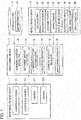
- Fig. 1 is a view explaining a configuration of an own-position estimation device according to the embodiment.
- the own-position estimation device according to the embodiment includes a peripheral sensor group 1, a processing device 3, a storage device 4, and a vehicle sensor group 5.
- the own-position estimation device according to the embodiment is mounted in a vehicle V (see Fig. 2 ) and estimates the position of the vehicle V.
- the position and attitude angle with a total of three degrees of freedom on a two-dimensional plane are estimated, the three degrees of freedom including: the position (X coordinate [m]) in the east-west direction (X-axis direction) and the position (Y coordinate [m]) in the north-south direction (Y-axis direction) which are the estimated own position of the vehicle V; and the azimuth angle ⁇ (yaw angle [rad]) of the vehicle which is attitude angle information.
- the peripheral sensor group 1 includes, for example, multiple laser range finders (LRFs) 101, 102 each configured to detect the distance to a target by using reflection of laser light casted on the target and multiple cameras 201, 202 each configured to capture a digital image which can be subjected to image processing. As described above, the peripheral sensor group 1 includes multiple sensors which detect landmarks present around the vehicle V.
- LRFs laser range finders
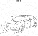
- Fig. 2 is an example illustrating a state where the peripheral sensor group 1 is mounted in the vehicle V.
- the LRFs 101, 102 can be mounted, for example, near left and right front fenders of the vehicle V.
- the LRFs 101, 102 each perform scanning within a predetermined scanning angle ⁇ (for example, 90°) with a turning axis of scanning extending in a front-rear direction D of the vehicle V such that trajectories of the emitted laser light form a plane perpendicular to a road surface.
- the LRFs 101, 102 can thereby detect landmarks such as curbs present in a left-right direction of the vehicle V.
- the LRFs 101, 102 output the shapes of the detected landmarks one after another to the processing device 3 as detection results.
- the cameras 201, 202 can be mounted in left and right door mirrors of the vehicle V.
- the cameras 201, 202 capture images by using, for example, solid state imaging elements such as CCDs or CMOSs.
- the cameras 201, 202 capture, for example, images of the road surface on lateral sides of the vehicle V.
- the cameras 201, 202 output the captured images to the processing device 3 one after another.
- the storage device 4 is a map information storage configured to store map information 41 including the positions of landmarks present around roads.
- the storage device 4 can be formed of a semiconductor memory, a magnetic disk, or the like.
- the landmarks recorded in the map information 41 include, for example, road surface signs indicating stop lines, pedestrian crossings, pedestrian crossing ahead signs, section lines, and the like, structures such as curbs, and various installations which can be detected by the peripheral sensor group 1.
- landmarks which actually have certain heights such as curbs are also described only by position information on a two-dimensional plane.
- the position information on each of curbs, white lines, and the like is defined by a collection of pieces of straight line information having two-dimensional information on both ends thereof.
- the map information 41 when a shape of a landmark in an actual environment is a curve, the landmark is described as pieces of straight line information on the two-dimensional plane approximately drawing the curve by polygonal lines.
- the vehicle sensor group 5 includes a GPS receiver 51, an accelerator sensor 52, a steering sensor 53, a brake sensor 54, a vehicle speed sensor 55, an acceleration sensor 56, a wheel speed sensor 57, and other sensors 58 such as a yaw rate sensor.
- the sensors 51 to 58 are connected to the processing device 3 and output various detection results to the processing device 3 one after another.
- the processing device 3 can calculate an approximant position of the vehicle V in the map information 41 by using the detection results of the vehicle sensor group 5 and calculate odometry indicating the movement amount of the vehicle V in a unit time.
- the processing device 3 includes a landmark position detector 31, a movement amount detector 32, a landmark position accumulator 33, a straight line extractor 34, a landmark position selector 35, and an own-position estimator 36.
- the processing device 3 can be formed of, for example, a microcontroller which is an integrated circuit including a central processing unit (CPU), a memory, an input-output I/F, and the like.
- the multiple information processors (31 to 36) forming the processing device 3 are implemented by the CPU executing a computer program installed in advance in the microcontroller.
- Parts forming the processing device 3 may be formed of an integral piece of hardware or separate pieces of hardware.
- the microcontroller may also serve as an electronic control unit (ECU) used for other control associated with the vehicle V such as, for example, automatic driving control.
- ECU electronice control unit
- the landmark position detector 31 detects the positions of landmarks present around the vehicle V relative to the vehicle V, based on the detection results of at least one of the LRFs 101, 102 and the cameras 201, 202.
- the positions detected by the landmark position detector 31 are positions in a vehicle coordinate system.
- the vehicle coordinate system is, for example, a system in which the center of the rear axle of the vehicle V is set as an origin, a forward direction is set as a positive direction of the x-axis, a leftward direction is set as a positive direction of the y-axis, and an upward direction is set as a positive direction of the z-axis.
- a formula for conversion from the coordinate systems of the LRFs 101, 102 and the cameras 201, 202 to the vehicle coordinate system is set in advance in the landmark position detector 31. Parameters of road surfaces in the vehicle coordinate system are similarly set.
- the movement amount detector 32 detects the odometry which is the movement amount of the vehicle V in the unit time, based on detection result information of at least one of the sensors included in the vehicle sensor group 5.
- the movement amount of the vehicle V is detected as a movement amount in an odometry coordinate system.
- the landmark position accumulator 33 accumulates, as pieces of landmark position data, the positions of the landmarks detected by the landmark position detector 31 in the past at predetermined intervals, based on the movement amount detected by the movement amount detector 32.
- the straight line extractor 34 extracts pieces of straight line information by using the pieces of landmark position data accumulated in the landmark position accumulator 33.
- the landmark position selector 35 selects the pieces of landmark position data from straight lines indicated by the pieces of straight line information extracted by the straight line extractor 34, based on the angles of 90° or smaller formed by the combinations of the intersecting straight lines.
- the own-position estimator 36 estimates the position of the vehicle V by matching the pieces of landmark position data selected by the landmark position selector 35 and the positions of the landmarks in the map information 41.
- the landmark position selector 35 sets the priorities of the pieces of straight line information such that the combinations of straight lines forming the angles of 90° or smaller are given a high priority in descending order of the formed angle. Then, the landmark position selector 35 selects the pieces of landmark position data in the descending order of the priorities set for the pieces of straight line information. Specifically, the landmark position selector 35 selects, from the pieces of landmark position data accumulated in the landmark position accumulator 33, the pieces of landmark position data corresponding to pieces of straight line information on at least the combination of the intersecting straight lines forming the largest angle among the angles of 90° or smaller formed by combinations of the intersecting straight lines.
- the landmark position selector 35 sets a high priority to each piece of straight line information in descending order of time of obtaining the corresponding piece of landmark position data. Then, the landmark position selector 35 selects the pieces of landmark position data in the descending order of the priorities set for the pieces of straight line information. The priority set for each piece of straight line information is changed from time to time based on the time of obtaining the corresponding pieces of landmark position data and the angle formed by the straight line which is an extended line of the piece of straight line information.
- the landmark position accumulator 33 determines the pieces of landmark position data to be accumulated based on the priority of each piece of straight line information set by the landmark position selector 35. Specifically, the landmark position accumulator 33 preferentially accumulates the pieces of landmark position data corresponding to the piece of straight line information with a high priority, and preferentially deletes the pieces of landmark position data corresponding to the piece of straight line information with a low priority.
- the landmark position detector 31 detects the position of each landmark around the vehicle V, based on the detection results of the peripheral sensor group 1.
- the landmark position detector 31 obtains the detection results of the LRFs 101, 102 and the cameras 201, 202 and detects the positions of the road surface signs such as section lines and stop lines and structures such as curbs and buildings in the vehicle coordinate system.
- Fig. 4 is an example illustrating an environment in which the vehicle V travels when performing the own-position estimation.
- the laser light emitted from the LRF 101 is casted on a road surface including a curb 61 as illustrated by a line 64.
- the landmark position detector 31 extracts a position where a shape changes greatly as the position of the curb 61, by using the direction and distance of the casted laser light, and detects the position (x, y, z) thereof in the vehicle coordinate system. Since it is possible to assume that the road surface is constantly present in the vertically downward direction of the LRFs 101, 102, the curb can be detected by comparing the height of each point with the height of the road surface and extracting a point of great change in height.
- the landmark position detector 31 detects white lines 62, 63 present on both sides of the vehicle V, by using luminance information of images captured by the cameras 201, 202.
- the landmark position detector 31 can detect a pattern of luminance change in which the luminance changes from dark to light and then to dark, in grayscale images captured by the cameras 201, 202 and thereby detect the centers of light portions as the white lines 62, 63.
- the positions (x, y, z) of the white lines 62, 63 in the vehicle coordinate system can be detected by using positional relationships between the road surface and the cameras 201, 202. Height information (z-axis component) of the positions (x, y, z) in the vehicle coordinate system detected in step S10 is excluded and the positions are hereafter handled as two-dimensional data.
- Part (a) to (d) of Fig. 5 are diagrams illustrating the position 71 of the curb 61 and the positions 72, 73 of the white lines 62, 63 in the vehicle coordinate system which are detected by the landmark position detector 31 in a period from time t1 to t4 in the example illustrated in Fig. 4 .
- the time t1 is the earliest time and the time t4 is the latest time.
- the movement amount detector 32 integrates the movement amount of the vehicle V calculated based on the detection results of the vehicle sensor group 5 to calculate the position of the vehicle V in the odometry coordinate system.
- the odometry coordinate system may be, for example, a system in which the position of the vehicle V at the time when the own-position estimation device is turned on or when processing is reset is set as an origin and the azimuth angle of the vehicle V at this time is set as 0°.
- the integration of the movement amount of the vehicle V is performed in the odometry coordinate system.
- Fig. 6 is a diagram illustrating the result of integrating the movement amount of the vehicle V calculated based on the detection results of the vehicle sensor group 5 in the example illustrated in parts (a) to (d) of Fig. 5 .
- the movement amount detector 32 thereby calculates the position (Xo, Yo) of the vehicle V in the odometry coordinate system.
- Fig. 7 is a diagram illustrating the pieces of landmark position data converted to pieces of data in the odometry coordinate system in the examples illustrated in Figs. 5 and 6 .
- the landmark position accumulator 33 converts the position of each landmark detected in step S10 to a piece of data in the odometry coordinate system based on the movement amount detected in step S20 and accumulates the piece of converted data as the piece of landmark position data.
- the straight line extractor 34 extracts each piece of straight line information by using the pieces of landmark position data accumulated in the landmark position accumulator 33.
- the straight line extractor 34 extracts a straight line by using the pieces of landmark position data obtained in a period from time t0 to t0+ ⁇ t, where ⁇ t is a unit time.
- the number of pieces of landmark position data obtainable in the unit time ⁇ t is determined depending on sampling periods of the LRFs 101, 102 and the cameras 201, 202.
- the straight line extractor 34 can determine whether the position of each landmark is on the left side or the right side of the vehicle V by determining whether the value of the y coordinate in the vehicle coordinate system is positive or negative. Accordingly, the straight line extractor 34 groups the pieces of landmark position data to pieces of data on the right side and pieces of data on the left side and then performs parameter estimation of each straight line.
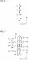
- Fig. 8 is a diagram illustrating pieces of straight line information N1, N2, N3 extracted by the straight line extractor 34 in the example illustrated in Fig. 7 .
- Point clouds indicated by the pieces of landmark position data are two-dimensional information.
- the straight line extractor 34 obtains the sum of distances between the estimated straight line and the respective points used for the estimation and, when the sum is equal to or greater than a predetermined threshold, does not extract the estimated straight line as the piece of straight line information.
- the straight line extractor 34 obtains points on the straight line closest to the respective points used for the estimation, selects two of the obtained points between which the distance is greatest as end points, and extracts the selected two points as the end points of the piece of straight line information.
- Points 71a and 71d are extracted as the end points of the piece of straight line information N1
- points 72a and 72d are extracted as the end points of the piece of straight line information N2
- points 73a and 73d are extracted as the end points of the piece of straight line information N3.
- the landmark position accumulator 33 accumulates the point cloud (landmark position data) used for the estimation of the straight line, the pieces of straight line information, and the obtained time t0+ ⁇ t in association with one another.
- the landmark position selector 35 sets the priorities of the pieces of straight line information such that the combinations of straight lines forming the angles arg are given a high priority in descending order of the formed angle.
- the landmark position selector 35 may set a high priority to each piece of straight line information in the descending order of the time of obtaining the corresponding piece of landmark position data.
- Fig. 9 is a diagram explaining the case where five pieces of straight line information a to e are extracted by the straight line extractor 34 while the vehicle V is traveling.
- the pieces of straight line information a, b, c, d, and e are obtained at time t1, t2, t3, t4, and t5, respectively.
- the time t1 is the earliest time and the time t5 is the latest time. In this case, as illustrated in Fig.
- the landmark position selector 35 first obtains combinations of the pieces of straight line information a to e and the angles of 90° or smaller formed by extended lines of the combinations of pieces of straight line information a to e, and sets the priorities for the combinations such that the combinations of straight lines forming the angles of 90° or smaller are given a high priority in descending order of the formed angle.
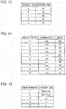
- the priorities of the respective combinations of the pieces of straight line information a to e are thereby determined as depicted in Fig. 11 .
- the priority is set for each combination of pieces of straight line information.
- the landmark position selector 35 thus further sets the priority of each piece of straight line information such that a high priority is set to each piece of straight information in descending order of time of obtaining the piece of straight line information or the piece of landmark position data.
- the times of obtaining the pieces of straight line information a, b, d which are set to have the highest priority in Fig. 11 are t1, t2, t4, respectively, in Fig. 10 , and the time of obtaining the piece of straight line information d is thus the latest followed by b and a.
- the priority of the piece of straight line information d is set to be highest followed by b and a as illustrated in Fig. 12 . Furthermore, the priorities of the pieces of straight line information c and e which are set to be the second highest following the priorities of the pieces of straight line information a, b, d in Fig. 11 are determined such that the priority of the piece of straight line information e is higher than c.
- step S50 the landmark position accumulator 33 stores the pieces of straight line information and the pieces of landmark position data in association, according to the priorities set in step S40.
- the landmark position accumulator 33 may delete the pieces of straight line information in the ascending order of priority.
- the own-position estimator 36 matches the pieces of landmark position data accumulated in the landmark position accumulator 33 and the positions of the landmarks in the map information 41 to estimate the position of the vehicle V. Specifically, the own-position estimator 36 estimates the position and attitude angle of the vehicle V with a total of three degrees of freedom which include the position (X coordinate) of the vehicle V in the east-west direction, the position (Y coordinate) of the vehicle V in the north-south direction, and the azimuth angle ⁇ (yaw angle ⁇ ) of the vehicle V.
- An ICP (Interactive Closest Point) algorithm can be used for the matching performed in step S50.
- the own-position estimator 36 performs matching for, for example, section lines, out of the positions of the landmarks included in the map information 41, by using the end points at both ends of each section line as evaluation points.
- the own-position estimation device extracts the pieces of straight line information by using the pieces of landmark position data and selects the pieces of landmark position data necessary for uniquely estimating the own position, based on the angles formed by the extended lines of the extracted pieces of straight line information.
- the own-position estimation device can thereby improve the accuracy of the own-position estimation of the vehicle.
- the own-position estimation device extracts the pieces of straight line information based on the landmarks around the vehicle and extracts at least one combination of extracted pieces of straight line information whose extended lines intersect each other, the own-position estimation device can uniquely estimate the own position.
- the own-position estimation device can perform the own-position estimation by using the pieces of landmark position data corresponding to the pieces of straight line information on the combination of the intersecting straight lines forming the largest angle among the angles of 90° or smaller formed by combinations of the intersecting straight lines.
- the own-position estimation device can thereby select the most reliable piece of data from the pieces of landmark position data necessary for uniquely estimating the own position.
- the own-position estimation device sets the priorities of the pieces of straight line information such that the combinations of straight lines forming the angles of 90° or smaller are given a high priority in descending order of the formed angle.
- the priorities are thereby set for the pieces of landmark position data in the descending order of usefulness in the own-position estimation and the accuracy of the own position estimation of the vehicle can be improved.
- the own-position estimation device sets a high priority to each piece of straight line information in descending order of time of obtaining the corresponding piece of landmark position data.
- the own-position estimation device can thereby select a recent piece of landmark position data which contributes greatly to the own-position estimation, and improve the accuracy of the own-position estimation of the vehicle.
- the landmark position accumulator 33 determines the pieces of landmark position data to be accumulated, based on the set priorities.
- the own-position estimation device according to the embodiment can thereby delete the pieces of data with low priorities when deletion of data becomes necessary due to reasons such as limited storage capacity. Accordingly, the own-position estimation device according to the embodiment can keep holding the pieces of landmark position data necessary for uniquely estimating the own position.
- the present invention can provide the own-position estimation device and the own-position estimation method which can improve the accuracy of the own-position estimation by selecting the pieces of data used for the own-position estimation based on the angles formed by the straight lines obtained by using the landmarks in the periphery.
Landscapes
- Engineering & Computer Science (AREA)
- Radar, Positioning & Navigation (AREA)
- Remote Sensing (AREA)
- Physics & Mathematics (AREA)
- General Physics & Mathematics (AREA)
- Automation & Control Theory (AREA)
- Electromagnetism (AREA)
- Computer Networks & Wireless Communication (AREA)
- Computer Vision & Pattern Recognition (AREA)
- Theoretical Computer Science (AREA)
- Multimedia (AREA)
- Aviation & Aerospace Engineering (AREA)
- Navigation (AREA)
- Traffic Control Systems (AREA)
Abstract
Description
- The present invention relates to an own-position estimation device and an own-position estimation method which estimate the position of a vehicle.
- There is known a method of estimating the position of a vehicle by matching map information and information detected by sensors such as a camera and a range finder. The accuracy of the own-position estimation can be improved by using map information with three-dimensional information, but this method has problems of an increase in the cost of creating the map information and an increase in the processing load of the own position estimation. Meanwhile, there is proposed a technique in which a mobile body estimates the position of itself by using map information having information on landmarks described as two-dimensional information (see Patent Literature 1). Such a technique can reduce the cost of creating the map information and the processing load of the own-position estimation.
- Patent Literature 1: Japanese Patent Application Publication No.
2008-250906 - However, the technique described in
Patent Literature 1 is based on the premise that the information obtained by the sensors and matched with the map information for the own-position estimation is information obtained within a predetermined distance from the latest own position. In this case, when a linear route continues for a predetermined distance or more and the information on the landmark is described as a straight line parallel to the route, there is a certain degree of freedom in the direction along the straight line and this may cause a decrease in accuracy of the own-position estimation. - In view of the problems described above, an object of the present invention is to provide an own-position estimation device and an own-position estimation method which can improve the accuracy of own-position estimation.
- An own-position estimation device selects, based on angles formed by intersecting lines among straight lines obtained by using landmarks therearound, pieces of landmark position data to be used for own-position estimation, and matches the selected pieces of landmark position data and the positions of the landmarks in map information to estimate the position of the vehicle.
- The present invention can provide the own-position estimation device and the own-position estimation method which can improve the accuracy of the own-position estimation by selecting, based on the angles formed by the intersecting straight lines among the straight lines obtained by using landmarks therearound, pieces of landmark position data to be used for the own-position estimation, the pieces of data to be used in the own-position estimation.
-
- [
Fig. 1] Fig. 1 is a block diagram explaining an example of a configuration of an own-position estimation device according to an embodiment of the present invention. - [
Fig. 2] Fig. 2 is an example illustrating laser range finders and cameras mounted in a vehicle. - [
Fig. 3] Fig. 3 is a flowchart explaining a processing flow of the own-position estimation device according to the embodiment of the present invention. - [
Fig. 4] Fig. 4 is an example illustrating an environment in which the vehicle mounted with the own-position estimation device according to the embodiment of the present invention travels. - [
Fig. 5] Fig. 5 is a view explaining a region specified by a region specifier included in the own-position estimation device according to the embodiment of the present invention. - [
Fig. 6] Fig. 6 is a diagram explaining processing performed by a landmark position detector included in the own-position estimation device according to the embodiment of the present invention. - [
Fig. 7] Fig. 7 is a diagram explaining processing performed by a movement amount detector included in the own-position estimation device according to the embodiment of the present invention. - [
Fig. 8] Fig. 8 is a diagram explaining processing performed by a straight line extractor included in the own-position estimation device according to the embodiment of the present invention. - [
Fig. 9] Fig. 9 is an example illustrating pieces of straight line information extracted by the straight line extractor while the vehicle is traveling. - [
Fig. 10] Fig. 10 is a table illustrating the pieces of straight line information extracted by the straight line extractor and obtained times. - [
Fig. 11] Fig. 11 is a table explaining a state where a priority is set for each combination of pieces of straight line information, based on angles formed by the intersecting straight lines. - [
Fig. 12] Fig. 12 is a table explaining a state where the priority is set for each piece of straight line information according to the obtained times and the angles formed by the intersecting straight lines. - An embodiment of the present invention is described with reference to the drawings. In the description of the drawings, the same or similar parts are denoted by the same or similar reference numerals and overlapping description is omitted.
-
Fig. 1 is a view explaining a configuration of an own-position estimation device according to the embodiment. The own-position estimation device according to the embodiment includes aperipheral sensor group 1, aprocessing device 3, astorage device 4, and avehicle sensor group 5. The own-position estimation device according to the embodiment is mounted in a vehicle V (seeFig. 2 ) and estimates the position of the vehicle V. - In the embodiment, the position and attitude angle with a total of three degrees of freedom on a two-dimensional plane are estimated, the three degrees of freedom including: the position (X coordinate [m]) in the east-west direction (X-axis direction) and the position (Y coordinate [m]) in the north-south direction (Y-axis direction) which are the estimated own position of the vehicle V; and the azimuth angle θ (yaw angle [rad]) of the vehicle which is attitude angle information.
- The
peripheral sensor group 1 includes, for example, multiple laser range finders (LRFs) 101, 102 each configured to detect the distance to a target by using reflection of laser light casted on the target andmultiple cameras peripheral sensor group 1 includes multiple sensors which detect landmarks present around the vehicle V. -
Fig. 2 is an example illustrating a state where theperipheral sensor group 1 is mounted in the vehicle V. TheLRFs LRFs LRFs processing device 3 as detection results. - For example, the
cameras cameras cameras cameras processing device 3 one after another. - The
storage device 4 is a map information storage configured to storemap information 41 including the positions of landmarks present around roads. Thestorage device 4 can be formed of a semiconductor memory, a magnetic disk, or the like. The landmarks recorded in themap information 41 include, for example, road surface signs indicating stop lines, pedestrian crossings, pedestrian crossing ahead signs, section lines, and the like, structures such as curbs, and various installations which can be detected by theperipheral sensor group 1. In themap information 41, landmarks which actually have certain heights such as curbs are also described only by position information on a two-dimensional plane. In themap information 41, the position information on each of curbs, white lines, and the like is defined by a collection of pieces of straight line information having two-dimensional information on both ends thereof. In themap information 41, when a shape of a landmark in an actual environment is a curve, the landmark is described as pieces of straight line information on the two-dimensional plane approximately drawing the curve by polygonal lines. - The
vehicle sensor group 5 includes aGPS receiver 51, anaccelerator sensor 52, asteering sensor 53, abrake sensor 54, avehicle speed sensor 55, anacceleration sensor 56, awheel speed sensor 57, andother sensors 58 such as a yaw rate sensor. Thesensors 51 to 58 are connected to theprocessing device 3 and output various detection results to theprocessing device 3 one after another. Theprocessing device 3 can calculate an approximant position of the vehicle V in themap information 41 by using the detection results of thevehicle sensor group 5 and calculate odometry indicating the movement amount of the vehicle V in a unit time. - The
processing device 3 includes alandmark position detector 31, amovement amount detector 32, alandmark position accumulator 33, astraight line extractor 34, alandmark position selector 35, and an own-position estimator 36. Theprocessing device 3 can be formed of, for example, a microcontroller which is an integrated circuit including a central processing unit (CPU), a memory, an input-output I/F, and the like. In this case, the multiple information processors (31 to 36) forming theprocessing device 3 are implemented by the CPU executing a computer program installed in advance in the microcontroller. Parts forming theprocessing device 3 may be formed of an integral piece of hardware or separate pieces of hardware. The microcontroller may also serve as an electronic control unit (ECU) used for other control associated with the vehicle V such as, for example, automatic driving control. - The
landmark position detector 31 detects the positions of landmarks present around the vehicle V relative to the vehicle V, based on the detection results of at least one of theLRFs cameras landmark position detector 31 are positions in a vehicle coordinate system. The vehicle coordinate system is, for example, a system in which the center of the rear axle of the vehicle V is set as an origin, a forward direction is set as a positive direction of the x-axis, a leftward direction is set as a positive direction of the y-axis, and an upward direction is set as a positive direction of the z-axis. Moreover, a formula for conversion from the coordinate systems of theLRFs cameras landmark position detector 31. Parameters of road surfaces in the vehicle coordinate system are similarly set. - The
movement amount detector 32 detects the odometry which is the movement amount of the vehicle V in the unit time, based on detection result information of at least one of the sensors included in thevehicle sensor group 5. The movement amount of the vehicle V is detected as a movement amount in an odometry coordinate system. Thelandmark position accumulator 33 accumulates, as pieces of landmark position data, the positions of the landmarks detected by thelandmark position detector 31 in the past at predetermined intervals, based on the movement amount detected by themovement amount detector 32. - The
straight line extractor 34 extracts pieces of straight line information by using the pieces of landmark position data accumulated in thelandmark position accumulator 33. Thelandmark position selector 35 selects the pieces of landmark position data from straight lines indicated by the pieces of straight line information extracted by thestraight line extractor 34, based on the angles of 90° or smaller formed by the combinations of the intersecting straight lines. The own-position estimator 36 estimates the position of the vehicle V by matching the pieces of landmark position data selected by thelandmark position selector 35 and the positions of the landmarks in themap information 41. - The
landmark position selector 35 sets the priorities of the pieces of straight line information such that the combinations of straight lines forming the angles of 90° or smaller are given a high priority in descending order of the formed angle. Then, thelandmark position selector 35 selects the pieces of landmark position data in the descending order of the priorities set for the pieces of straight line information. Specifically, thelandmark position selector 35 selects, from the pieces of landmark position data accumulated in thelandmark position accumulator 33, the pieces of landmark position data corresponding to pieces of straight line information on at least the combination of the intersecting straight lines forming the largest angle among the angles of 90° or smaller formed by combinations of the intersecting straight lines. - The
landmark position selector 35 sets a high priority to each piece of straight line information in descending order of time of obtaining the corresponding piece of landmark position data. Then, thelandmark position selector 35 selects the pieces of landmark position data in the descending order of the priorities set for the pieces of straight line information. The priority set for each piece of straight line information is changed from time to time based on the time of obtaining the corresponding pieces of landmark position data and the angle formed by the straight line which is an extended line of the piece of straight line information. - The
landmark position accumulator 33 determines the pieces of landmark position data to be accumulated based on the priority of each piece of straight line information set by thelandmark position selector 35. Specifically, thelandmark position accumulator 33 preferentially accumulates the pieces of landmark position data corresponding to the piece of straight line information with a high priority, and preferentially deletes the pieces of landmark position data corresponding to the piece of straight line information with a low priority. - An example of an own-position estimation method using the own-position estimation device according to the embodiment is described with reference to the flowchart of
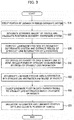
Fig. 3 . - First, in step S10, the
landmark position detector 31 detects the position of each landmark around the vehicle V, based on the detection results of theperipheral sensor group 1. Thelandmark position detector 31 obtains the detection results of theLRFs cameras -
Fig. 4 is an example illustrating an environment in which the vehicle V travels when performing the own-position estimation. In the example illustrated inFig. 4 , the laser light emitted from theLRF 101 is casted on a road surface including acurb 61 as illustrated by aline 64. Thelandmark position detector 31 extracts a position where a shape changes greatly as the position of thecurb 61, by using the direction and distance of the casted laser light, and detects the position (x, y, z) thereof in the vehicle coordinate system. Since it is possible to assume that the road surface is constantly present in the vertically downward direction of theLRFs - Moreover, the
landmark position detector 31 detectswhite lines cameras landmark position detector 31 can detect a pattern of luminance change in which the luminance changes from dark to light and then to dark, in grayscale images captured by thecameras white lines white lines cameras - Part (a) to (d) of
Fig. 5 are diagrams illustrating the position 71 of thecurb 61 and the positions 72, 73 of thewhite lines landmark position detector 31 in a period from time t1 to t4 in the example illustrated inFig. 4 . The time t1 is the earliest time and the time t4 is the latest time. - In step S20, the
movement amount detector 32 integrates the movement amount of the vehicle V calculated based on the detection results of thevehicle sensor group 5 to calculate the position of the vehicle V in the odometry coordinate system. The odometry coordinate system may be, for example, a system in which the position of the vehicle V at the time when the own-position estimation device is turned on or when processing is reset is set as an origin and the azimuth angle of the vehicle V at this time is set as 0°. The integration of the movement amount of the vehicle V is performed in the odometry coordinate system. -
Fig. 6 is a diagram illustrating the result of integrating the movement amount of the vehicle V calculated based on the detection results of thevehicle sensor group 5 in the example illustrated in parts (a) to (d) ofFig. 5 . Themovement amount detector 32 thereby calculates the position (Xo, Yo) of the vehicle V in the odometry coordinate system. -
Fig. 7 is a diagram illustrating the pieces of landmark position data converted to pieces of data in the odometry coordinate system in the examples illustrated inFigs. 5 and6 . Thelandmark position accumulator 33 converts the position of each landmark detected in step S10 to a piece of data in the odometry coordinate system based on the movement amount detected in step S20 and accumulates the piece of converted data as the piece of landmark position data. - In step S30, the
straight line extractor 34 extracts each piece of straight line information by using the pieces of landmark position data accumulated in thelandmark position accumulator 33. Thestraight line extractor 34 extracts a straight line by using the pieces of landmark position data obtained in a period from time t0 to t0+Δt, where Δt is a unit time. The number of pieces of landmark position data obtainable in the unit time Δt is determined depending on sampling periods of theLRFs cameras straight line extractor 34 can determine whether the position of each landmark is on the left side or the right side of the vehicle V by determining whether the value of the y coordinate in the vehicle coordinate system is positive or negative. Accordingly, thestraight line extractor 34 groups the pieces of landmark position data to pieces of data on the right side and pieces of data on the left side and then performs parameter estimation of each straight line. -
Fig. 8 is a diagram illustrating pieces of straight line information N1, N2, N3 extracted by thestraight line extractor 34 in the example illustrated inFig. 7 . Point clouds indicated by the pieces of landmark position data are two-dimensional information. Accordingly, thestraight line extractor 34 can estimate each straight line by applying a straight line ax+by+c = 0 to points pi = (xi, yi) detected as the white line or the curb and obtaining optimal parameters a, b, c. Thestraight line extractor 34 obtains the sum of distances between the estimated straight line and the respective points used for the estimation and, when the sum is equal to or greater than a predetermined threshold, does not extract the estimated straight line as the piece of straight line information. When the sum is less than the threshold, thestraight line extractor 34 obtains points on the straight line closest to the respective points used for the estimation, selects two of the obtained points between which the distance is greatest as end points, and extracts the selected two points as the end points of the piece of straight line information.Points landmark position accumulator 33 accumulates the point cloud (landmark position data) used for the estimation of the straight line, the pieces of straight line information, and the obtained time t0+Δt in association with one another. - In step S40, the
landmark position selector 35 reads the end points of the pieces of straight line information accumulated in thelandmark position accumulator 33 and obtains the angles of 90° or smaller formed by straight lines which pass the end points of the pieces of straight line information and which are extended lines of the pieces of straight line information. Since each piece of straight line information is accumulated as two end points in thelandmark position accumulator 33, when the two end points are expressed as ps = (xs, ys), pe (xe, ye), the direction vector of the piece of straight line information can be expressed as V = (xe-xs, ye-ys). - Moreover, when the direction vectors of certain two pieces of straight information are expressed as Vi and Vj, an angle argij of 90° or smaller formed by extended lines of the two pieces of straight line information can be obtained as follows:

- (when aij exceeds 90 degrees) argij = 180-aij
- (when aij is 90 degrees or smaller) argij = aij.
- The
landmark position selector 35 sets the priorities of the pieces of straight line information such that the combinations of straight lines forming the angles arg are given a high priority in descending order of the formed angle. When the priorities of the pieces of straight line information based on the angles are the same, thelandmark position selector 35 may set a high priority to each piece of straight line information in the descending order of the time of obtaining the corresponding piece of landmark position data. -
Fig. 9 is a diagram explaining the case where five pieces of straight line information a to e are extracted by thestraight line extractor 34 while the vehicle V is traveling. As depicted inFig. 10 , the pieces of straight line information a, b, c, d, and e are obtained at time t1, t2, t3, t4, and t5, respectively. The time t1 is the earliest time and the time t5 is the latest time. In this case, as illustrated inFig. 11 , thelandmark position selector 35 first obtains combinations of the pieces of straight line information a to e and the angles of 90° or smaller formed by extended lines of the combinations of pieces of straight line information a to e, and sets the priorities for the combinations such that the combinations of straight lines forming the angles of 90° or smaller are given a high priority in descending order of the formed angle. The priorities of the respective combinations of the pieces of straight line information a to e are thereby determined as depicted inFig. 11 . - In the state depicted in
Fig. 11 , the priority is set for each combination of pieces of straight line information. Thelandmark position selector 35 thus further sets the priority of each piece of straight line information such that a high priority is set to each piece of straight information in descending order of time of obtaining the piece of straight line information or the piece of landmark position data. For example, the times of obtaining the pieces of straight line information a, b, d which are set to have the highest priority inFig. 11 are t1, t2, t4, respectively, inFig. 10 , and the time of obtaining the piece of straight line information d is thus the latest followed by b and a. Hence, the priority of the piece of straight line information d is set to be highest followed by b and a as illustrated inFig. 12 . Furthermore, the priorities of the pieces of straight line information c and e which are set to be the second highest following the priorities of the pieces of straight line information a, b, d inFig. 11 are determined such that the priority of the piece of straight line information e is higher than c. - In step S50, the
landmark position accumulator 33 stores the pieces of straight line information and the pieces of landmark position data in association, according to the priorities set in step S40. When the storage capacity of thelandmark position accumulator 33 is limited, thelandmark position accumulator 33 may delete the pieces of straight line information in the ascending order of priority. - In step S60, the own-
position estimator 36 matches the pieces of landmark position data accumulated in thelandmark position accumulator 33 and the positions of the landmarks in themap information 41 to estimate the position of the vehicle V. Specifically, the own-position estimator 36 estimates the position and attitude angle of the vehicle V with a total of three degrees of freedom which include the position (X coordinate) of the vehicle V in the east-west direction, the position (Y coordinate) of the vehicle V in the north-south direction, and the azimuth angle θ (yaw angle θ) of the vehicle V. - An ICP (Interactive Closest Point) algorithm can be used for the matching performed in step S50. In this case, the own-
position estimator 36 performs matching for, for example, section lines, out of the positions of the landmarks included in themap information 41, by using the end points at both ends of each section line as evaluation points. Moreover, the closer the piece of landmark position data is to the vehicle V (peripheral sensor group 1), the less the effect of the odometry error is. Accordingly, the own-position estimator 36 can increase the number of evaluation points for areas near the vehicle V by performing linear interpolation and reduce the number of evaluation points for areas far from the vehicle V. - As described above, the own-position estimation device according to the embodiment extracts the pieces of straight line information by using the pieces of landmark position data and selects the pieces of landmark position data necessary for uniquely estimating the own position, based on the angles formed by the extended lines of the extracted pieces of straight line information. The own-position estimation device according to the embodiment can thereby improve the accuracy of the own-position estimation of the vehicle. Moreover, since the own-position estimation device according to the embodiment extracts the pieces of straight line information based on the landmarks around the vehicle and extracts at least one combination of extracted pieces of straight line information whose extended lines intersect each other, the own-position estimation device can uniquely estimate the own position.
- Furthermore, the own-position estimation device according to the embodiment can perform the own-position estimation by using the pieces of landmark position data corresponding to the pieces of straight line information on the combination of the intersecting straight lines forming the largest angle among the angles of 90° or smaller formed by combinations of the intersecting straight lines. The own-position estimation device according to the embodiment can thereby select the most reliable piece of data from the pieces of landmark position data necessary for uniquely estimating the own position.
- Moreover, the own-position estimation device according to the embodiment sets the priorities of the pieces of straight line information such that the combinations of straight lines forming the angles of 90° or smaller are given a high priority in descending order of the formed angle. The priorities are thereby set for the pieces of landmark position data in the descending order of usefulness in the own-position estimation and the accuracy of the own position estimation of the vehicle can be improved.
- Furthermore, the own-position estimation device according to the embodiment sets a high priority to each piece of straight line information in descending order of time of obtaining the corresponding piece of landmark position data. The own-position estimation device according to the embodiment can thereby select a recent piece of landmark position data which contributes greatly to the own-position estimation, and improve the accuracy of the own-position estimation of the vehicle.
- Moreover, in the own-position estimation device according to the embodiment, the
landmark position accumulator 33 determines the pieces of landmark position data to be accumulated, based on the set priorities. The own-position estimation device according to the embodiment can thereby delete the pieces of data with low priorities when deletion of data becomes necessary due to reasons such as limited storage capacity. Accordingly, the own-position estimation device according to the embodiment can keep holding the pieces of landmark position data necessary for uniquely estimating the own position. - Although the present invention has been described above by using the aforementioned embodiment, it should not be understood that the description and drawings forming part of this disclosure limit the present invention. From this disclosure, various alternative embodiments, examples, and operations techniques will be found by those skilled in the art. The present invention includes various embodiments and the like which are not described herein such as configurations mutually adopting the aforementioned configurations, as a matter of course. Accordingly, the technical scope of the present invention should be determined only by the matters specifying the invention in the scope of claims regarded as appropriate based on the aforementioned description.
- The present invention can provide the own-position estimation device and the own-position estimation method which can improve the accuracy of the own-position estimation by selecting the pieces of data used for the own-position estimation based on the angles formed by the straight lines obtained by using the landmarks in the periphery.
-
- V
- vehicle
- 4
- storage device (map information storage)
- 31
- landmark position detector
- 32
- movement amount detector
- 33
- landmark position accumulator
- 34
- straight line extractor
- 35
- landmark position selector
- 36
- own-position estimator
- 41
- map information
Claims (6)
- An own-position estimation device comprising:a landmark position detector configured to detect positions of landmarks present around a vehicle;a movement amount detector configured to detect a movement amount of the vehicle;a landmark position accumulator configured to accumulate the positions of the landmarks detected by the landmark position detector as landmark position data, based on the movement amount detected by the movement amount detector;a straight line extractor configured to extract straight lines from the landmark position data accumulated in the landmark position accumulator;a landmark position selector configured to select pieces of the landmark position data based on angles formed by intersecting ones of the straight lines extracted by the straight line extractor;a map information storage configured to store map information including positions of landmarks; andan own-position estimator configured to estimate a position of the vehicle by matching the pieces of the landmark position data selected by the landmark position selector and the positions of the landmarks in the map information.
- The own-position estimation device according to claim 1, wherein the landmark position selector selects the pieces of the landmark position data corresponding to pieces of straight line information on at least a combination of the intersecting straight lines forming a largest angle among angles of 90° or smaller formed by combinations of the intersecting straight lines.
- The own-position estimation device according to claim 1 or 2, wherein the landmark position selector sets priorities of pieces of straight line information such that the greater the angles formed by the intersecting ones of the straight lines equal to or less than 90° are, the higher the priority is set to combinations of the intersecting ones of the straight lines, and selects the pieces of the landmark position data in a descending order of the priorities set for the straight lines.
- The own-position estimation device according to claim 3, wherein the landmark position sets priorities of the pieces of straight line information such that the later times of obtaining the pieces of the landmark position data are, the higher the priority is set to the pieces of straight line information corresponding to the pieces of the landmark position data, and selects the pieces of the landmark position data in a descending order of the priorities set for the pieces of straight line information.
- The own-position estimation device according to claim 3 or 4, wherein the landmark position accumulator determines the pieces of the landmark position data to be accumulated based on the priorities.
- An own position estimation method comprising:detecting positions of landmarks present around a vehicle;detecting a movement amount of the vehicle;converting the detected positions of the landmarks based on the detected movement amount and accumulating the converted positions as landmark position data;extracting straight lines from the accumulated landmark position data;selecting pieces of the landmark position data based on angles formed by intersecting ones of the extracted straight lines; andestimating a position of the vehicle by matching the selected pieces of the landmark position data and positions of landmarks in map information.
Applications Claiming Priority (1)
| Application Number | Priority Date | Filing Date | Title |
|---|---|---|---|
| PCT/JP2015/070008 WO2017009923A1 (en) | 2015-07-13 | 2015-07-13 | Own-position estimating device and own-position estimating method |
Publications (3)
| Publication Number | Publication Date |
|---|---|
| EP3324152A1 true EP3324152A1 (en) | 2018-05-23 |
| EP3324152A4 EP3324152A4 (en) | 2018-08-08 |
| EP3324152B1 EP3324152B1 (en) | 2019-04-03 |
Family
ID=57757193
Family Applications (1)
| Application Number | Title | Priority Date | Filing Date |
|---|---|---|---|
| EP15898239.7A Active EP3324152B1 (en) | 2015-07-13 | 2015-07-13 | Own-position estimating device and own-position estimating method |
Country Status (10)
| Country | Link |
|---|---|
| US (1) | US10145693B2 (en) |
| EP (1) | EP3324152B1 (en) |
| JP (1) | JP6477882B2 (en) |
| KR (1) | KR101887335B1 (en) |
| CN (1) | CN107850446B (en) |
| BR (1) | BR112018000704B1 (en) |
| CA (1) | CA2992006C (en) |
| MX (1) | MX366083B (en) |
| RU (1) | RU2669652C1 (en) |
| WO (1) | WO2017009923A1 (en) |
Cited By (2)
| Publication number | Priority date | Publication date | Assignee | Title |
|---|---|---|---|---|
| KR20210027458A (en) * | 2018-07-04 | 2021-03-10 | 르노 에스.아.에스. | Driving support method and driving support device |
| RU2776105C1 (en) * | 2018-07-04 | 2022-07-13 | Ниссан Мотор Ко., Лтд. | Method for movement assistance and apparatus for movement assistance |
Families Citing this family (25)
| Publication number | Priority date | Publication date | Assignee | Title |
|---|---|---|---|---|
| MX364577B (en) * | 2015-08-28 | 2019-05-02 | Nissan Motor | Vehicle position estimation device, vehicle position estimation method. |
| KR101847836B1 (en) * | 2015-12-24 | 2018-04-11 | 현대자동차주식회사 | Road boundary detection system and method, and vehicle using the same |
| US11573325B2 (en) | 2016-03-11 | 2023-02-07 | Kaarta, Inc. | Systems and methods for improvements in scanning and mapping |
| WO2018140701A1 (en) * | 2017-01-27 | 2018-08-02 | Kaarta, Inc. | Laser scanner with real-time, online ego-motion estimation |
| US11567201B2 (en) | 2016-03-11 | 2023-01-31 | Kaarta, Inc. | Laser scanner with real-time, online ego-motion estimation |
| US10989542B2 (en) | 2016-03-11 | 2021-04-27 | Kaarta, Inc. | Aligning measured signal data with slam localization data and uses thereof |
| WO2017155970A1 (en) | 2016-03-11 | 2017-09-14 | Kaarta, Inc. | Laser scanner with real-time, online ego-motion estimation |
| BR112019001508B1 (en) * | 2016-07-26 | 2022-11-01 | Nissan Motor Co., Ltd | SELF-POSITION ESTIMATE METHOD AND SELF-POSITION ESTIMATE DEVICE |
| US10802450B2 (en) | 2016-09-08 | 2020-10-13 | Mentor Graphics Corporation | Sensor event detection and fusion |
| US10678240B2 (en) | 2016-09-08 | 2020-06-09 | Mentor Graphics Corporation | Sensor modification based on an annotated environmental model |
| US10317901B2 (en) | 2016-09-08 | 2019-06-11 | Mentor Graphics Development (Deutschland) Gmbh | Low-level sensor fusion |
| US11067996B2 (en) | 2016-09-08 | 2021-07-20 | Siemens Industry Software Inc. | Event-driven region of interest management |
| US10650270B2 (en) * | 2017-04-21 | 2020-05-12 | X Development Llc | Methods and systems for simultaneous localization and calibration |
| US20180314253A1 (en) | 2017-05-01 | 2018-11-01 | Mentor Graphics Development (Deutschland) Gmbh | Embedded automotive perception with machine learning classification of sensor data |
| WO2019099605A1 (en) | 2017-11-17 | 2019-05-23 | Kaarta, Inc. | Methods and systems for geo-referencing mapping systems |
| JP2019109332A (en) * | 2017-12-18 | 2019-07-04 | パイオニア株式会社 | Map data structure |
| JP7251918B2 (en) * | 2017-12-18 | 2023-04-04 | ジオテクノロジーズ株式会社 | Vehicle position estimation device and vehicle position estimation system |
| US11145146B2 (en) | 2018-01-31 | 2021-10-12 | Mentor Graphics (Deutschland) Gmbh | Self-diagnosis of faults in an autonomous driving system |
| US10553044B2 (en) | 2018-01-31 | 2020-02-04 | Mentor Graphics Development (Deutschland) Gmbh | Self-diagnosis of faults with a secondary system in an autonomous driving system |
| WO2019165194A1 (en) | 2018-02-23 | 2019-08-29 | Kaarta, Inc. | Methods and systems for processing and colorizing point clouds and meshes |
| WO2019195270A1 (en) | 2018-04-03 | 2019-10-10 | Kaarta, Inc. | Methods and systems for real or near real-time point cloud map data confidence evaluation |
| WO2020009826A1 (en) | 2018-07-05 | 2020-01-09 | Kaarta, Inc. | Methods and systems for auto-leveling of point clouds and 3d models |
| EP4134627A4 (en) * | 2020-04-08 | 2023-05-24 | Nissan Motor Co., Ltd. | Map information correction method, driving assistance method, and map information correction device |
| US11872965B2 (en) * | 2020-05-11 | 2024-01-16 | Hunter Engineering Company | System and method for gyroscopic placement of vehicle ADAS targets |
| JP7241839B1 (en) | 2021-10-06 | 2023-03-17 | 三菱電機株式会社 | Self-localization device |
Family Cites Families (13)
| Publication number | Priority date | Publication date | Assignee | Title |
|---|---|---|---|---|
| US7287884B2 (en) * | 2002-02-07 | 2007-10-30 | Toyota Jidosha Kabushiki Kaisha | Vehicle operation supporting device and vehicle operation supporting system |
| JP2007303841A (en) | 2006-05-08 | 2007-11-22 | Toyota Central Res & Dev Lab Inc | Vehicle position estimation device |
| JP4437556B2 (en) * | 2007-03-30 | 2010-03-24 | アイシン・エィ・ダブリュ株式会社 | Feature information collecting apparatus and feature information collecting method |
| JP2008250906A (en) | 2007-03-30 | 2008-10-16 | Sogo Keibi Hosho Co Ltd | Mobile robot, and self-location correction method and program |
| CN101968940B (en) * | 2009-07-28 | 2012-08-22 | 钰程科技股份有限公司 | Handheld device with positioning and picture taking capability and geographical positioning method thereof |
| JP2012194860A (en) * | 2011-03-17 | 2012-10-11 | Murata Mach Ltd | Traveling vehicle |
| JP2013068482A (en) | 2011-09-21 | 2013-04-18 | Nec Casio Mobile Communications Ltd | Azimuth direction correction system, terminal device, server device, azimuth direction correction method and program |
| JP5810939B2 (en) * | 2012-01-26 | 2015-11-11 | トヨタ自動車株式会社 | Vehicle road identification device |
| JP5761162B2 (en) * | 2012-11-30 | 2015-08-12 | トヨタ自動車株式会社 | Vehicle position estimation device |
| KR102027771B1 (en) * | 2013-01-31 | 2019-10-04 | 한국전자통신연구원 | Obstacle detecting apparatus and method for adaptation to vehicle velocity |
| JP6233706B2 (en) * | 2013-04-02 | 2017-11-22 | パナソニックIpマネジメント株式会社 | Autonomous mobile device and self-position estimation method of autonomous mobile device |
| CN103398717B (en) * | 2013-08-22 | 2016-04-20 | 成都理想境界科技有限公司 | The location of panoramic map database acquisition system and view-based access control model, air navigation aid |
| JP2016176769A (en) * | 2015-03-19 | 2016-10-06 | クラリオン株式会社 | Information processing device and vehicle position detection method |
-
2015
- 2015-07-13 WO PCT/JP2015/070008 patent/WO2017009923A1/en active Application Filing
- 2015-07-13 JP JP2017528030A patent/JP6477882B2/en active Active
- 2015-07-13 EP EP15898239.7A patent/EP3324152B1/en active Active
- 2015-07-13 US US15/743,853 patent/US10145693B2/en active Active
- 2015-07-13 CN CN201580081657.8A patent/CN107850446B/en active Active
- 2015-07-13 CA CA2992006A patent/CA2992006C/en active Active
- 2015-07-13 MX MX2018000438A patent/MX366083B/en active IP Right Grant
- 2015-07-13 RU RU2018105102A patent/RU2669652C1/en active
- 2015-07-13 BR BR112018000704-8A patent/BR112018000704B1/en active IP Right Grant
- 2015-07-13 KR KR1020187000810A patent/KR101887335B1/en active IP Right Grant
Cited By (4)
| Publication number | Priority date | Publication date | Assignee | Title |
|---|---|---|---|---|
| KR20210027458A (en) * | 2018-07-04 | 2021-03-10 | 르노 에스.아.에스. | Driving support method and driving support device |
| CN112673230A (en) * | 2018-07-04 | 2021-04-16 | 日产自动车株式会社 | Driving assistance method and driving assistance device |
| EP3819594A4 (en) * | 2018-07-04 | 2021-07-28 | Nissan Motor Co., Ltd. | Travel assistance method and travel assistance device |
| RU2776105C1 (en) * | 2018-07-04 | 2022-07-13 | Ниссан Мотор Ко., Лтд. | Method for movement assistance and apparatus for movement assistance |
Also Published As
| Publication number | Publication date |
|---|---|
| CN107850446B (en) | 2019-01-01 |
| MX366083B (en) | 2019-06-27 |
| RU2669652C1 (en) | 2018-10-12 |
| US20180202815A1 (en) | 2018-07-19 |
| BR112018000704A2 (en) | 2018-09-18 |
| EP3324152A4 (en) | 2018-08-08 |
| WO2017009923A1 (en) | 2017-01-19 |
| JP6477882B2 (en) | 2019-03-06 |
| KR101887335B1 (en) | 2018-08-09 |
| BR112018000704B1 (en) | 2022-11-29 |
| CN107850446A (en) | 2018-03-27 |
| JPWO2017009923A1 (en) | 2018-06-14 |
| CA2992006C (en) | 2018-08-21 |
| KR20180016567A (en) | 2018-02-14 |
| EP3324152B1 (en) | 2019-04-03 |
| MX2018000438A (en) | 2018-05-17 |
| US10145693B2 (en) | 2018-12-04 |
| CA2992006A1 (en) | 2017-01-19 |
Similar Documents
| Publication | Publication Date | Title |
|---|---|---|
| EP3324152B1 (en) | Own-position estimating device and own-position estimating method | |
| JP6567659B2 (en) | Lane detection device and lane detection method | |
| CA2987373C (en) | Position estimation device and position estimation method | |
| US10832061B2 (en) | Traveling road boundary estimation apparatus and traveling assistance system using same | |
| EP2933790B1 (en) | Moving object location/attitude angle estimation device and moving object location/attitude angle estimation method | |
| JP6222353B2 (en) | Target detection apparatus and target detection method | |
| JP5966747B2 (en) | Vehicle travel control apparatus and method | |
| US7542835B2 (en) | Vehicle image processing device | |
| WO2018061084A1 (en) | Self-position estimation method and self-position estimation device | |
| EP2924655B1 (en) | Disparity value deriving device, equipment control system, movable apparatus, robot, disparity value deriving method, and computer-readable storage medium | |
| JP6838365B2 (en) | Self-position estimation method and self-position estimation device | |
| JP6834401B2 (en) | Self-position estimation method and self-position estimation device | |
| JP6604052B2 (en) | Runway boundary estimation device and runway boundary estimation method | |
| JP2013183311A (en) | Estimation device and detection system of attitude angle in on-vehicle camera | |
| EP3540643A1 (en) | Image processing apparatus and image processing method | |
| JP2013039881A (en) | Device for estimating shape of travel road |
Legal Events
| Date | Code | Title | Description |
|---|---|---|---|
| STAA | Information on the status of an ep patent application or granted ep patent |
Free format text: STATUS: THE INTERNATIONAL PUBLICATION HAS BEEN MADE |
|
| PUAI | Public reference made under article 153(3) epc to a published international application that has entered the european phase |
Free format text: ORIGINAL CODE: 0009012 |
|
| STAA | Information on the status of an ep patent application or granted ep patent |
Free format text: STATUS: REQUEST FOR EXAMINATION WAS MADE |
|
| 17P | Request for examination filed |
Effective date: 20180208 |
|
| AK | Designated contracting states |
Kind code of ref document: A1 Designated state(s): AL AT BE BG CH CY CZ DE DK EE ES FI FR GB GR HR HU IE IS IT LI LT LU LV MC MK MT NL NO PL PT RO RS SE SI SK SM TR |
|
| AX | Request for extension of the european patent |
Extension state: BA ME |
|
| A4 | Supplementary search report drawn up and despatched |
Effective date: 20180705 |
|
| RIC1 | Information provided on ipc code assigned before grant |
Ipc: G01C 21/30 20060101AFI20180629BHEP Ipc: G01S 5/16 20060101ALI20180629BHEP Ipc: G01C 21/36 20060101ALI20180629BHEP Ipc: G06K 9/00 20060101ALI20180629BHEP Ipc: G08G 1/00 20060101ALI20180629BHEP |
|
| RIC1 | Information provided on ipc code assigned before grant |
Ipc: G01C 21/36 20060101ALI20180904BHEP Ipc: G06K 9/00 20060101ALI20180904BHEP Ipc: G08G 1/00 20060101ALI20180904BHEP Ipc: G01C 21/30 20060101AFI20180904BHEP Ipc: G01S 5/16 20060101ALI20180904BHEP |
|
| DAV | Request for validation of the european patent (deleted) | ||
| DAX | Request for extension of the european patent (deleted) | ||
| GRAP | Despatch of communication of intention to grant a patent |
Free format text: ORIGINAL CODE: EPIDOSNIGR1 |
|
| STAA | Information on the status of an ep patent application or granted ep patent |
Free format text: STATUS: GRANT OF PATENT IS INTENDED |
|
| INTG | Intention to grant announced |
Effective date: 20181112 |
|
| GRAS | Grant fee paid |
Free format text: ORIGINAL CODE: EPIDOSNIGR3 |
|
| GRAA | (expected) grant |
Free format text: ORIGINAL CODE: 0009210 |
|
| STAA | Information on the status of an ep patent application or granted ep patent |
Free format text: STATUS: THE PATENT HAS BEEN GRANTED |
|
| AK | Designated contracting states |
Kind code of ref document: B1 Designated state(s): AL AT BE BG CH CY CZ DE DK EE ES FI FR GB GR HR HU IE IS IT LI LT LU LV MC MK MT NL NO PL PT RO RS SE SI SK SM TR |
|
| REG | Reference to a national code |
Ref country code: GB Ref legal event code: FG4D |
|
| REG | Reference to a national code |
Ref country code: CH Ref legal event code: EP Ref country code: AT Ref legal event code: REF Ref document number: 1116288 Country of ref document: AT Kind code of ref document: T Effective date: 20190415 |
|
| REG | Reference to a national code |
Ref country code: DE Ref legal event code: R096 Ref document number: 602015027841 Country of ref document: DE |
|
| REG | Reference to a national code |
Ref country code: IE Ref legal event code: FG4D |
|
| REG | Reference to a national code |
Ref country code: NL Ref legal event code: MP Effective date: 20190403 |
|
| REG | Reference to a national code |
Ref country code: LT Ref legal event code: MG4D |
|
| REG | Reference to a national code |
Ref country code: AT Ref legal event code: MK05 Ref document number: 1116288 Country of ref document: AT Kind code of ref document: T Effective date: 20190403 |
|
| PG25 | Lapsed in a contracting state [announced via postgrant information from national office to epo] |
Ref country code: NL Free format text: LAPSE BECAUSE OF FAILURE TO SUBMIT A TRANSLATION OF THE DESCRIPTION OR TO PAY THE FEE WITHIN THE PRESCRIBED TIME-LIMIT Effective date: 20190403 |
|
| PG25 | Lapsed in a contracting state [announced via postgrant information from national office to epo] |
Ref country code: AL Free format text: LAPSE BECAUSE OF FAILURE TO SUBMIT A TRANSLATION OF THE DESCRIPTION OR TO PAY THE FEE WITHIN THE PRESCRIBED TIME-LIMIT Effective date: 20190403 Ref country code: CZ Free format text: LAPSE BECAUSE OF FAILURE TO SUBMIT A TRANSLATION OF THE DESCRIPTION OR TO PAY THE FEE WITHIN THE PRESCRIBED TIME-LIMIT Effective date: 20190403 Ref country code: ES Free format text: LAPSE BECAUSE OF FAILURE TO SUBMIT A TRANSLATION OF THE DESCRIPTION OR TO PAY THE FEE WITHIN THE PRESCRIBED TIME-LIMIT Effective date: 20190403 Ref country code: PT Free format text: LAPSE BECAUSE OF FAILURE TO SUBMIT A TRANSLATION OF THE DESCRIPTION OR TO PAY THE FEE WITHIN THE PRESCRIBED TIME-LIMIT Effective date: 20190803 Ref country code: NO Free format text: LAPSE BECAUSE OF FAILURE TO SUBMIT A TRANSLATION OF THE DESCRIPTION OR TO PAY THE FEE WITHIN THE PRESCRIBED TIME-LIMIT Effective date: 20190703 Ref country code: SE Free format text: LAPSE BECAUSE OF FAILURE TO SUBMIT A TRANSLATION OF THE DESCRIPTION OR TO PAY THE FEE WITHIN THE PRESCRIBED TIME-LIMIT Effective date: 20190403 Ref country code: HR Free format text: LAPSE BECAUSE OF FAILURE TO SUBMIT A TRANSLATION OF THE DESCRIPTION OR TO PAY THE FEE WITHIN THE PRESCRIBED TIME-LIMIT Effective date: 20190403 Ref country code: LT Free format text: LAPSE BECAUSE OF FAILURE TO SUBMIT A TRANSLATION OF THE DESCRIPTION OR TO PAY THE FEE WITHIN THE PRESCRIBED TIME-LIMIT Effective date: 20190403 Ref country code: FI Free format text: LAPSE BECAUSE OF FAILURE TO SUBMIT A TRANSLATION OF THE DESCRIPTION OR TO PAY THE FEE WITHIN THE PRESCRIBED TIME-LIMIT Effective date: 20190403 |
|
| PG25 | Lapsed in a contracting state [announced via postgrant information from national office to epo] |
Ref country code: LV Free format text: LAPSE BECAUSE OF FAILURE TO SUBMIT A TRANSLATION OF THE DESCRIPTION OR TO PAY THE FEE WITHIN THE PRESCRIBED TIME-LIMIT Effective date: 20190403 Ref country code: RS Free format text: LAPSE BECAUSE OF FAILURE TO SUBMIT A TRANSLATION OF THE DESCRIPTION OR TO PAY THE FEE WITHIN THE PRESCRIBED TIME-LIMIT Effective date: 20190403 Ref country code: BG Free format text: LAPSE BECAUSE OF FAILURE TO SUBMIT A TRANSLATION OF THE DESCRIPTION OR TO PAY THE FEE WITHIN THE PRESCRIBED TIME-LIMIT Effective date: 20190703 Ref country code: GR Free format text: LAPSE BECAUSE OF FAILURE TO SUBMIT A TRANSLATION OF THE DESCRIPTION OR TO PAY THE FEE WITHIN THE PRESCRIBED TIME-LIMIT Effective date: 20190704 Ref country code: PL Free format text: LAPSE BECAUSE OF FAILURE TO SUBMIT A TRANSLATION OF THE DESCRIPTION OR TO PAY THE FEE WITHIN THE PRESCRIBED TIME-LIMIT Effective date: 20190403 |
|
| PG25 | Lapsed in a contracting state [announced via postgrant information from national office to epo] |
Ref country code: IS Free format text: LAPSE BECAUSE OF FAILURE TO SUBMIT A TRANSLATION OF THE DESCRIPTION OR TO PAY THE FEE WITHIN THE PRESCRIBED TIME-LIMIT Effective date: 20190803 Ref country code: AT Free format text: LAPSE BECAUSE OF FAILURE TO SUBMIT A TRANSLATION OF THE DESCRIPTION OR TO PAY THE FEE WITHIN THE PRESCRIBED TIME-LIMIT Effective date: 20190403 |
|
| REG | Reference to a national code |
Ref country code: DE Ref legal event code: R097 Ref document number: 602015027841 Country of ref document: DE |
|
| PG25 | Lapsed in a contracting state [announced via postgrant information from national office to epo] |
Ref country code: SK Free format text: LAPSE BECAUSE OF FAILURE TO SUBMIT A TRANSLATION OF THE DESCRIPTION OR TO PAY THE FEE WITHIN THE PRESCRIBED TIME-LIMIT Effective date: 20190403 Ref country code: DK Free format text: LAPSE BECAUSE OF FAILURE TO SUBMIT A TRANSLATION OF THE DESCRIPTION OR TO PAY THE FEE WITHIN THE PRESCRIBED TIME-LIMIT Effective date: 20190403 Ref country code: EE Free format text: LAPSE BECAUSE OF FAILURE TO SUBMIT A TRANSLATION OF THE DESCRIPTION OR TO PAY THE FEE WITHIN THE PRESCRIBED TIME-LIMIT Effective date: 20190403 Ref country code: RO Free format text: LAPSE BECAUSE OF FAILURE TO SUBMIT A TRANSLATION OF THE DESCRIPTION OR TO PAY THE FEE WITHIN THE PRESCRIBED TIME-LIMIT Effective date: 20190403 |
|
| PLBE | No opposition filed within time limit |
Free format text: ORIGINAL CODE: 0009261 |
|
| STAA | Information on the status of an ep patent application or granted ep patent |
Free format text: STATUS: NO OPPOSITION FILED WITHIN TIME LIMIT |
|
| PG25 | Lapsed in a contracting state [announced via postgrant information from national office to epo] |
Ref country code: MC Free format text: LAPSE BECAUSE OF FAILURE TO SUBMIT A TRANSLATION OF THE DESCRIPTION OR TO PAY THE FEE WITHIN THE PRESCRIBED TIME-LIMIT Effective date: 20190403 Ref country code: SM Free format text: LAPSE BECAUSE OF FAILURE TO SUBMIT A TRANSLATION OF THE DESCRIPTION OR TO PAY THE FEE WITHIN THE PRESCRIBED TIME-LIMIT Effective date: 20190403 Ref country code: IT Free format text: LAPSE BECAUSE OF FAILURE TO SUBMIT A TRANSLATION OF THE DESCRIPTION OR TO PAY THE FEE WITHIN THE PRESCRIBED TIME-LIMIT Effective date: 20190403 |
|
| REG | Reference to a national code |
Ref country code: CH Ref legal event code: PL |
|
| 26N | No opposition filed |
Effective date: 20200106 |
|
| PG25 | Lapsed in a contracting state [announced via postgrant information from national office to epo] |
Ref country code: TR Free format text: LAPSE BECAUSE OF FAILURE TO SUBMIT A TRANSLATION OF THE DESCRIPTION OR TO PAY THE FEE WITHIN THE PRESCRIBED TIME-LIMIT Effective date: 20190403 |
|
| REG | Reference to a national code |
Ref country code: BE Ref legal event code: MM Effective date: 20190731 |
|
| PG25 | Lapsed in a contracting state [announced via postgrant information from national office to epo] |
Ref country code: LI Free format text: LAPSE BECAUSE OF NON-PAYMENT OF DUE FEES Effective date: 20190731 Ref country code: SI Free format text: LAPSE BECAUSE OF FAILURE TO SUBMIT A TRANSLATION OF THE DESCRIPTION OR TO PAY THE FEE WITHIN THE PRESCRIBED TIME-LIMIT Effective date: 20190403 Ref country code: LU Free format text: LAPSE BECAUSE OF NON-PAYMENT OF DUE FEES Effective date: 20190713 Ref country code: BE Free format text: LAPSE BECAUSE OF NON-PAYMENT OF DUE FEES Effective date: 20190731 Ref country code: CH Free format text: LAPSE BECAUSE OF NON-PAYMENT OF DUE FEES Effective date: 20190731 |
|
| PG25 | Lapsed in a contracting state [announced via postgrant information from national office to epo] |
Ref country code: IE Free format text: LAPSE BECAUSE OF NON-PAYMENT OF DUE FEES Effective date: 20190713 |
|
| PG25 | Lapsed in a contracting state [announced via postgrant information from national office to epo] |
Ref country code: CY Free format text: LAPSE BECAUSE OF FAILURE TO SUBMIT A TRANSLATION OF THE DESCRIPTION OR TO PAY THE FEE WITHIN THE PRESCRIBED TIME-LIMIT Effective date: 20190403 |
|
| PG25 | Lapsed in a contracting state [announced via postgrant information from national office to epo] |
Ref country code: MT Free format text: LAPSE BECAUSE OF FAILURE TO SUBMIT A TRANSLATION OF THE DESCRIPTION OR TO PAY THE FEE WITHIN THE PRESCRIBED TIME-LIMIT Effective date: 20190403 Ref country code: HU Free format text: LAPSE BECAUSE OF FAILURE TO SUBMIT A TRANSLATION OF THE DESCRIPTION OR TO PAY THE FEE WITHIN THE PRESCRIBED TIME-LIMIT; INVALID AB INITIO Effective date: 20150713 |
|
| PG25 | Lapsed in a contracting state [announced via postgrant information from national office to epo] |
Ref country code: MK Free format text: LAPSE BECAUSE OF FAILURE TO SUBMIT A TRANSLATION OF THE DESCRIPTION OR TO PAY THE FEE WITHIN THE PRESCRIBED TIME-LIMIT Effective date: 20190403 |
|
| PGFP | Annual fee paid to national office [announced via postgrant information from national office to epo] |
Ref country code: DE Payment date: 20230620 Year of fee payment: 9 |
|
| PGFP | Annual fee paid to national office [announced via postgrant information from national office to epo] |
Ref country code: GB Payment date: 20240620 Year of fee payment: 10 |
|
| PGFP | Annual fee paid to national office [announced via postgrant information from national office to epo] |
Ref country code: FR Payment date: 20240619 Year of fee payment: 10 |