EP3324121A1 - Gas turbine combustor - Google Patents
Gas turbine combustor Download PDFInfo
- Publication number
- EP3324121A1 EP3324121A1 EP17202608.0A EP17202608A EP3324121A1 EP 3324121 A1 EP3324121 A1 EP 3324121A1 EP 17202608 A EP17202608 A EP 17202608A EP 3324121 A1 EP3324121 A1 EP 3324121A1
- Authority
- EP
- European Patent Office
- Prior art keywords
- fuel nozzle
- section
- fuel
- gas turbine
- nozzle plate
- Prior art date
- Legal status (The legal status is an assumption and is not a legal conclusion. Google has not performed a legal analysis and makes no representation as to the accuracy of the status listed.)
- Granted
Links
Images


Classifications
-
- F—MECHANICAL ENGINEERING; LIGHTING; HEATING; WEAPONS; BLASTING
- F23—COMBUSTION APPARATUS; COMBUSTION PROCESSES
- F23R—GENERATING COMBUSTION PRODUCTS OF HIGH PRESSURE OR HIGH VELOCITY, e.g. GAS-TURBINE COMBUSTION CHAMBERS
- F23R3/00—Continuous combustion chambers using liquid or gaseous fuel
- F23R3/28—Continuous combustion chambers using liquid or gaseous fuel characterised by the fuel supply
- F23R3/38—Continuous combustion chambers using liquid or gaseous fuel characterised by the fuel supply comprising rotary fuel injection means
-
- F—MECHANICAL ENGINEERING; LIGHTING; HEATING; WEAPONS; BLASTING
- F23—COMBUSTION APPARATUS; COMBUSTION PROCESSES
- F23R—GENERATING COMBUSTION PRODUCTS OF HIGH PRESSURE OR HIGH VELOCITY, e.g. GAS-TURBINE COMBUSTION CHAMBERS
- F23R3/00—Continuous combustion chambers using liquid or gaseous fuel
- F23R3/28—Continuous combustion chambers using liquid or gaseous fuel characterised by the fuel supply
- F23R3/283—Attaching or cooling of fuel injecting means including supports for fuel injectors, stems, or lances
-
- F—MECHANICAL ENGINEERING; LIGHTING; HEATING; WEAPONS; BLASTING
- F23—COMBUSTION APPARATUS; COMBUSTION PROCESSES
- F23R—GENERATING COMBUSTION PRODUCTS OF HIGH PRESSURE OR HIGH VELOCITY, e.g. GAS-TURBINE COMBUSTION CHAMBERS
- F23R3/00—Continuous combustion chambers using liquid or gaseous fuel
- F23R3/28—Continuous combustion chambers using liquid or gaseous fuel characterised by the fuel supply
- F23R3/286—Continuous combustion chambers using liquid or gaseous fuel characterised by the fuel supply having fuel-air premixing devices
-
- F—MECHANICAL ENGINEERING; LIGHTING; HEATING; WEAPONS; BLASTING
- F02—COMBUSTION ENGINES; HOT-GAS OR COMBUSTION-PRODUCT ENGINE PLANTS
- F02C—GAS-TURBINE PLANTS; AIR INTAKES FOR JET-PROPULSION PLANTS; CONTROLLING FUEL SUPPLY IN AIR-BREATHING JET-PROPULSION PLANTS
- F02C3/00—Gas-turbine plants characterised by the use of combustion products as the working fluid
- F02C3/04—Gas-turbine plants characterised by the use of combustion products as the working fluid having a turbine driving a compressor
-
- F—MECHANICAL ENGINEERING; LIGHTING; HEATING; WEAPONS; BLASTING
- F05—INDEXING SCHEMES RELATING TO ENGINES OR PUMPS IN VARIOUS SUBCLASSES OF CLASSES F01-F04
- F05D—INDEXING SCHEME FOR ASPECTS RELATING TO NON-POSITIVE-DISPLACEMENT MACHINES OR ENGINES, GAS-TURBINES OR JET-PROPULSION PLANTS
- F05D2220/00—Application
- F05D2220/30—Application in turbines
- F05D2220/32—Application in turbines in gas turbines
-
- F—MECHANICAL ENGINEERING; LIGHTING; HEATING; WEAPONS; BLASTING
- F05—INDEXING SCHEMES RELATING TO ENGINES OR PUMPS IN VARIOUS SUBCLASSES OF CLASSES F01-F04
- F05D—INDEXING SCHEME FOR ASPECTS RELATING TO NON-POSITIVE-DISPLACEMENT MACHINES OR ENGINES, GAS-TURBINES OR JET-PROPULSION PLANTS
- F05D2240/00—Components
- F05D2240/35—Combustors or associated equipment
-
- F—MECHANICAL ENGINEERING; LIGHTING; HEATING; WEAPONS; BLASTING
- F05—INDEXING SCHEMES RELATING TO ENGINES OR PUMPS IN VARIOUS SUBCLASSES OF CLASSES F01-F04
- F05D—INDEXING SCHEME FOR ASPECTS RELATING TO NON-POSITIVE-DISPLACEMENT MACHINES OR ENGINES, GAS-TURBINES OR JET-PROPULSION PLANTS
- F05D2250/00—Geometry
- F05D2250/10—Two-dimensional
- F05D2250/13—Two-dimensional trapezoidal
- F05D2250/131—Two-dimensional trapezoidal polygonal
-
- F—MECHANICAL ENGINEERING; LIGHTING; HEATING; WEAPONS; BLASTING
- F23—COMBUSTION APPARATUS; COMBUSTION PROCESSES
- F23R—GENERATING COMBUSTION PRODUCTS OF HIGH PRESSURE OR HIGH VELOCITY, e.g. GAS-TURBINE COMBUSTION CHAMBERS
- F23R2900/00—Special features of, or arrangements for continuous combustion chambers; Combustion processes therefor
- F23R2900/00005—Preventing fatigue failures or reducing mechanical stress in gas turbine components
Definitions
- the present invention relates to a gas turbine combustor.
- gas turbine combustor In a gas turbine, for the purpose of reducing a load of exhaust gas on the environment, a strict environment standard is set for NOx emitted during driving. Since an emission amount of NOx increases according to a rise in flame temperature, in a combustor of the gas turbine (hereinafter referred to as "gas turbine combustor” or “combustor”), it is necessary to suppress formation of a locally high-temperature flame in a combustion chamber and achieve uniform combustion. In order to perform the uniform combustion in the combustion chamber, it is necessary to set, in the gas turbine combustor, a large number of fuel nozzles for injecting fuel and improve dispersiveness of the fuel.
- JP 2009-014297 discloses an example of a gas turbine combustor including a plurality of fuel nozzles.
- a parallel male screw is provided at the rear end portion (the upstream portion) of the fuel nozzle and a parallel female screw is provided on the inner circumference portion of a fuel nozzle setting hole of a fuel nozzle header.
- the fuel nozzle is fixed to the fuel nozzle header by fastening the screws to each other.
- An object of the present invention is to provide a gas turbine combustor having structural reliability against vibration of fuel nozzles caused by fluid force and high environmental performance by uniform combustion in a combustion chamber.
- a gas turbine combustor of the present invention comprises a fuel nozzle configured to inject fuel, and a fuel nozzle plate including a hole section into which an insertion section located in a root part of the fuel nozzle is inserted.
- the fuel nozzle includes a male screw section at least on an outer circumferential surface of a downstream portion viewed from a flowing direction of the fuel in the insertion section.
- the fuel nozzle plate includes a female screw section in the hole section. The female screw section screws with the male screw section.
- the fuel nozzle includes the insertion section. An upstream end portion of the insertion section is metallurgically joined to an upstream end portion of the fuel nozzle plate.
- a gas turbine combustor which has structural reliability against vibration of fuel nozzles caused by fluid force and high environmental performance by uniform combustion in a combustion chamber.
- FIG. 1 is a diagram showing an example of the configuration of a gas turbine plant including a gas turbine combustor according to an embodiment of the present invention.
- a combustor 7 is shown in a sectional view in Fig. 1 .
- a gas turbine plant 1 includes a compressor 3, a combustor 7, a gas turbine 8, and a generator 9.
- the compressor 3 takes in air 2 from the atmosphere and compresses the air 2.
- the combustor 7 burns compressed air 4 generated by the compressor 3 and fuel 5 and generates a high-temperature and high-pressure combustion gas 6.
- the gas turbine 8 is driven by the combustion gas 6 generated by the combustor 7 and extracts energy of the combustion gas 6 as rotation power.
- the generator 9 generates electric power using the rotation power of the gas turbine 8.
- the combustor 7 includes an end flange 10, an outer cylinder 11, a burner 17, a liner 15, and a combustion chamber 22.
- the burner 17 includes a perforated plate 12, a fuel nozzle plate 13, and a plurality of fuel nozzles 14.
- the compressed air 4 generated by the compressor 3 passes a channel 16 between the outer cylinder 11 and the liner 15 and flows into the burner 17. A part of the compressed air 4 flows into the liner 15 as cooling air 18 for cooling the liner 15.
- the fuel 5 passes a fuel supply pipe 19 of the end flange 10, flows into the fuel nozzle plate 13, and flows in fuel channels of the fuel nozzles 14 to be injected to the perforated plate 12 from the fuel nozzles 14.
- the fuel 5 injected from the fuel nozzles 14 and the compressed air 4 flowing into the burner 17 are mixed.
- An air fuel mixture 21 of the fuel 5 and the compressed air 4 is injected toward the combustion chamber 22 to form a flame 23.
- the fuel 5 not only natural gas but also other gases, such as coke oven gas, refinery-off gas, and coal-gasified gas, can be used.
- upstream and downstream mean directions defined by the flow of the fuel 5.
- Fig. 1 the left side is upstream and the right side is downstream.
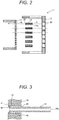
- Fig. 2 is an exploded view showing components of the burner 17.
- the burner 17 is shown in a sectional view in Fig. 2 .
- the burner 17 includes the perforated plate 12, the fuel nozzle plate 13, and the plurality of fuel nozzles 14.
- the fuel nozzle 14 includes a fuel channel 14a inside the fuel nozzle 14, in which the fuel 5 flows.
- the fuel nozzle 14 is supported by the fuel nozzle plate 13 so as to extend from the upstream side to the downstream side.
- the fuel nozzle 14 injects the fuel 5 to the downstream side, which is supplied from the upstream side.
- the fuel nozzle plate 13 includes a fuel nozzle attachment hole 44 which is a hole section.
- the fuel nozzle 14 is set in the fuel nozzle attachment hole 44.
- the fuel nozzle plate 13 supports the fuel nozzle 14 and supplies the fuel 5 to the fuel nozzle 14, which flows in from the upstream side.
- An upstream end portion 30 of the fuel nozzle 14 is metallurgically joined to an upstream end portion 41 of the fuel nozzle plate 13.
- a joining section of the upstream end portion 30 and the upstream end portion 41 is sealed such that the fuel 5 does not leak.
- a downstream end portion 31 of the fuel nozzle 14 is not in contact with the air hole 20 of the perforated plate 12 so that the compressed air 4 can freely flow into the air hole 20.
- the upstream end portion 30 of the fuel nozzle 14 and the upstream end portion 41 of the fuel nozzle plate 13 are joined to each other by welding, brazing, or the like. In the following description, an example is described in which the upstream end portion 30 of the fuel nozzle 14 and the upstream end portion 41 of the fuel nozzle plate 13 are joined to each other by welding.
- a configuration of a burner in particular, a configuration in which a fuel nozzle is fixed to a fuel nozzle plate is described for a conventional gas turbine combustor.
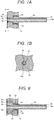
- Fig. 3 is a diagram showing a configuration in which the fuel nozzle 14 is fixed to the fuel nozzle plate 13 in the burner in a conventional gas turbine combustor and is a sectional view of the fuel nozzle 14 and the fuel nozzle plate 13.
- the upstream end portion 30 of the fuel nozzle 14 is joined to the upstream end portion 41 of the fuel nozzle plate 13 by welding.
- the fuel nozzle 14 is fixed to the fuel nozzle plate 13 by this welding.
- a portion where the upstream end portion 30 of the fuel nozzle 14 and the upstream end portion 41 of the fuel nozzle plate 13 are joined is referred to as "joining section 45".
- a portion where the fuel nozzle 14 is supported by the fuel nozzle plate 13, that is, a portion located in a root part of the fuel nozzle 14 and lying in the fuel nozzle attachment hole 44 is referred to as "insertion section 46".
- the outer circumferential surface of the insertion section 46 of the fuel nozzle 14 and the wall surface of the fuel nozzle attachment hole 44 of the fuel nozzle plate 13 are in contact to reduce a load acting on the joining section 45 (vibrational stress acting on the joining section 45).
- a frictional force occurs according to the contact of the outer circumferential surface of the insertion section 46 of the fuel nozzle 14 and the wall surface of the fuel nozzle attachment hole 44 of the fuel nozzle plate 13. Vibration of the fuel nozzle 14 is attenuated by the frictional force.
- the conventional gas turbine combustor includes a gap between the outer circumferential surface of the insertion section 46 of the fuel nozzle 14 and the wall surface of the fuel nozzle attachment hole 44 of the fuel nozzle plate 13, the contact of the outer circumferential surface of the insertion section 46 of the fuel nozzle 14 and the wall surface of the fuel nozzle attachment hole 44 of the fuel nozzle plate 13 sometimes cannot be sufficiently obtained. Therefore, the effect of the attenuation of the vibration of the fuel nozzle 14 is not sufficient in the conventional gas turbine combustor.
- the fuel nozzle 14 includes a screw section (a portion having a thread ridge) at least on the outer circumferential surface of a down stream portion of the insertion section 46 and has a configuration in which the upstream end portion 30 of the insertion section 46 is metallurgically joined to the fuel nozzle plate 13.
- the downstream portion of the insertion section 46 of the fuel nozzle 14 is a portion including the downstream end portion of the insertion section 46 of the fuel nozzle 14.
- the screw section provided at least on the outer circumferential surface of the downstream portion of the insertion section 46 of the fuel nozzle 14 screws with a screw section provided on the wall surface of the fuel nozzle attachment hole 44 of the fuel nozzle plate 13.
- Vibration of the fuel nozzle 14 can be attenuated by frictional force caused by the contact of the screw sections .
- at least the downstream portion of the insertion section 46 of the fuel nozzle 14 screws with the fuel nozzle plate 13. Therefore, it is possible to further increase the frictional force caused by the contact of the fuel nozzle 14 and the fuel nozzle plate 13 than in the conventional gas turbine combustor shown in Fig. 3 . It is therefore possible to improve attenuation performance against the vibration of the fuel nozzle 14.
- the fuel nozzle 14 is mainly supported by the fuel nozzle plate 13 in the screw section of the insertion section 46. It is possible to improve the attenuation performance against the vibration of the fuel nozzle 14. It is possible to secure high structural reliability against the vibration of the fuel nozzle 14. In a gas turbine combustor according to embodiments of the present invention, it is possible to secure high structural reliability without expanding the outer diameter of the fuel nozzle 14. Therefore, it is possible to increase the number of fuel nozzles 14 to achieve uniform combustion in the combustion chamber 22 and obtain high environmental performance.
- Fig. 4 is a diagram showing a configuration in which the fuel nozzle 14 is fixed to the fuel nozzle plate 13 in a burner in a gas turbine combustor according to the first embodiment of the present invention and is a sectional view of the fuel nozzle 14 and the fuel nozzle plate 13.
- the fuel nozzle 14 includes a screw section (a male screw section) 51 on the entire outer circumferential surface of the insertion section 46.
- the fuel nozzle plate 13 includes the fuel nozzle attachment hole 44 which is a hole section into which the insertion section 46 located in the root part of the fuel nozzle 14 is inserted, and includes a screw section (a female screw section) 81 in a portion that supports the fuel nozzle 14 (a position corresponding to the screw section 51 of the fuel nozzle 14) on the wall surface of the fuel nozzle attachment hole 44.
- the screw section (the male screw section) 51 of the fuel nozzle 14 screws with the screw section (the female screw section) 81 of the fuel nozzle plate 13.
- the upstream end portion 30 of the insertion section 46 of the fuel nozzle 14 is metallurgically joined to the upstream end portion 41 of the fuel nozzle plate 13.
- the joining section 45 where the fuel nozzle 14 and the fuel nozzle plate 13 are metallurgically joined together, plays a role of a seal between the fuel nozzle 14 and the fuel nozzle plate 13 and a rotation stopper for the fuel nozzle 14.
- Fig. 5 is a sectional view of the fuel nozzle 14 and the fuel nozzle plate 13, showing a modification of the configuration shown in Fig. 4 in which the fuel nozzle plate 13 and the fuel nozzle 14 are fixed to each other.
- the fuel nozzle 14 includes the screw section (the male screw section) 51 only on the outer circumferential surface of a downstream portion 50 of the insertion section 46.
- the fuel nozzle plate 13 includes the screw section (the female screw section) 81 in a position corresponding to the screw section 51 of the fuel nozzle 14 on the wall surface of the fuel nozzle attachment hole 44.
- the screw section (the male screw section) 51 of the fuel nozzle 14 is screwed with the screw section (the female screw section) 81 of the fuel nozzle plate 13.
- the upstream end portion 30 of the insertion section 46 of the fuel nozzle 14 is metallurgically joined to the upstream end portion 41 of the fuel nozzle plate 13 in the joining section 45.
- the fuel nozzle 14 is structurally supported with respect to the fuel nozzle plate 13 mainly by the screw section 51.
- the fuel nozzle 14 includes the screw section 51 at least on the outer circumferential surface of the downstream portion 50 of the insertion section 46.
- the fuel nozzle plate 13 includes the screw section 81 on the wall surface of the fuel nozzle attachment hole 44. Therefore, even if the fuel nozzle 14 vibrates due to fluid force or the like, it is possible to obtain high attenuation performance against the vibration of the fuel nozzle 14 by friction of the screw section 51 and the screw section 81.
- the fuel nozzle 14 is supported by the fuel nozzle plate 13, mainly by the screw section 51, it is possible to reduce load (vibrational stress) acting on the joining section 45 present on the upstream side of the insertion section 46.
- load vibrational stress
- the gas turbine combustor according to this embodiment it is possible to improve structural reliability with such a configuration.
- the fuel nozzle 14 When the fuel nozzle 14 vibrates due to fluid force or the like, vibration amplitude of the downstream end portion 31, which is the distal end of a portion projecting from the fuel nozzle plate 13, is the largest in the fuel nozzle 14.
- the fuel nozzle 14 is metallurgically joined to the fuel nozzle plate 13 in the joining section 45 at the upstream end portion 30.
- the vibration is attenuated by friction between the fuel nozzle 14 and the fuel nozzle plate 13 in the screw section 51 between the joining section 45 and the downstream end portion 31.
- the fuel nozzle 14 is joined to the fuel nozzle plate 13 in a position (the upstream end portion 30) most distant from the downstream end portion 31 where the vibration amplitude is the largest. Therefore, it is possible to further increase the friction between the fuel nozzle plate 13 and the screw section 51 present between the joining section 45 and the downstream end portion 31, and it is possible to further increase a vibration attenuation effect by this friction.
- the length of the presence of the screw section 51 (the length in a flowing direction of the fuel 5, that is, the length in the axial direction of the fuel nozzle 14) is desirably 20% or more of the length of a portion of the fuel nozzle 14 projecting from the fuel nozzle plate 13 (the distance between the fuel nozzle plate 13 and the downstream end portion 31 of the fuel nozzle 14) .
- the screw section 51 has such length, it is considered possible to effectively attenuate the vibration of the fuel nozzle 14.
- the outer diameter of the insertion section 46 is larger than the outer diameter of the portion projecting from the fuel nozzle plate 13. Note that, in the fuel nozzle 14, the outer diameter of the insertion section 46 and the outer diameter of the portion projecting from the fuel nozzle plate 13 may be the same.
- Fig. 6 is a diagram showing a configuration in which the fuel nozzle 14 is fixed to the fuel nozzle plate 13 in a burner in a gas turbine combustor according to the second embodiment of the present invention and is a sectional view of the fuel nozzle 14 and the fuel nozzle plate 13.
- the insertion section 46 includes the downstream portion 50 and an upstream portion 62.
- the upstream portion 62 of the insertion section 46 of the fuel nozzle 14 is a portion including the upstream end portion 30 of the insertion section 46 of the fuel nozzle 14.
- the fuel nozzle 14 includes the screw section (the male screw section) 51 only on the outer circumferential surface of the downstream portion 50 of the insertion section 46.
- a root diameter of the screw section 51 (a diameter in a portion of a groove of the screw section 51) is larger than the outer diameter of the upstream portion 62 of the insertion section 46.
- the fuel nozzle 14 does not include the screw section 51 on the outer circumferential surface of the upstream portion 62.
- the fuel nozzle plate 13 includes the fuel nozzle attachment hole 44 having a shape corresponding to the fuel nozzle 14.
- the wall surface of the fuel nozzle attachment hole 44 includes the screw section (the female screw section) 81 in a position corresponding to the screw section 51 of the fuel nozzle 14.
- the fuel nozzle 14 includes a step section 60 that connects the downstream portion 50 and the upstream portion 62 of the insertion section 46.
- the fuel nozzle plate 13 includes a step section 61 on the wall surface of the fuel nozzle attachment hole 44.
- the step section 61 has a shape corresponding to the step section 60 of the fuel nozzle 14.
- the step section 60 of the fuel nozzle 14 and the step section 61 of the fuel nozzle plate 13 are in contact with each other.
- the step section 60 of the fuel nozzle 14 and the step section 61 of the fuel nozzle plate 13 are surfaces desirably perpendicular to the axial direction (the length direction) of the fuel nozzle 14.
- the screw section (the male screw section) 51 of the fuel nozzle 14 is screwed with the screw section (the female screw section) 81 of the fuel nozzle plate 13.
- the upstreamendportion 30 of the insertion section 46 of the fuel nozzle 14 is metallurgically joined to the upstream end portion 41 of the fuel nozzle plate 13 in the joining section 45.
- the gas turbine combustor according to this embodiment has a structure that the fuel nozzle 14 is screwed into the fuel nozzle plate 13 from the downstream side when the burner 17 is assembled.
- the gas turbine combustor according to this embodiment has an effect that it is easy to position the fuel nozzle 14 in the axial direction (the length direction) by setting the step section 60 of the fuel nozzle 14 and the step section 61 of the fuel nozzle plate 13 in contact with each other when the burner 17 is assembled. Therefore, in the gas turbine combustor according to this embodiment, it is possible to accurately assemble the burner 17 and obtain high structural reliability against the vibration of the fuel nozzle 14.
- Fig. 7A is a diagram showing a configuration in which the fuel nozzle 14 is fixed to the fuel nozzle plate 13 in a burner in a gas turbine combustor according to the third embodiment of the present invention and is a sectional view of the fuel nozzle 14 and the fuel nozzle plate 13.
- Fig. 7B is a sectional view of the fuel nozzle 14 and the fuel nozzle plate 13 taken along a cutting plane line A-A shown in Fig. 7A .
- the burner 17 of the gas turbine combustor according to this embodiment includes the following configuration in addition to the configuration of the burner 17 of the gas turbine combustor according to the second embodiment. That is, the fuel nozzle 14 has a polygonal cross section at the upstream end portion 70 of the fuel channel 14a, and the cross section is perpendicular to the fuel channel 14a.
- the fuel nozzle 14 When the burner 17 is assembled, the fuel nozzle 14 is inserted into the fuel nozzle attachment hole 44 of the fuel nozzle plate 13 from the downstream side. The fuel nozzle 14 is rotated such that the screw section (the male screw section) 51 of the fuel nozzle 14 screws with the screw section (the female screw section) 81 of the fuel nozzle plate 13. Work for rotating the fuel nozzle 14 is sometimes performed by inserting a tool (e.g., a wrench) into the fuel channel 14a from the upstream end portion 70 of the fuel channel 14a.
- a tool e.g., a wrench
- the cross section perpendicular to the fuel channel 14a has a polygonal shape such that a tool can be inserted into the fuel channel 14a from the upstream end portion 70 to rotate the fuel nozzle 14.
- the shape of the cross section of the upstream end portion 70 of the fuel channel 14a can be decided according to the shape of a tool used for the assembly of the burner 17.
- Fig. 7A and Fig. 7B show an example in which the shape of the cross section of the upstream end portion 70 of the fuel channel 14a is a hexagon. In the example shown in Fig. 7A and Fig. 7B , it is possible to screw the fuel nozzle 14 into the fuel nozzle plate 13 using a hexagonal wrench key (hex key).
- the upstream end portion 70 of the fuel channel 14a of the fuel nozzle 14 has a shape corresponding to the shape of a tool used for the assembly of the burner 17. Therefore, it is possible to surely assemble the burner 17 and obtain high structural reliability against the vibration of the fuel nozzle 14.
- the gas turbine combustor according to the first embodiment also can have a configuration in which the upstream end portion 70 of the fuel channel 14a of the fuel nozzle 14 has a polygonal-shaped cross section perpendicular to the fuel channel 14a.
- Fig. 8 is a diagram showing a configuration in which the fuel nozzle 14 is fixed to the fuel nozzle plate 13 in a burner in a gas turbine combustor according to the fourth embodiment of the present invention and is a sectional view of the fuel nozzle 14 and the fuel nozzle plate 13.
- the insertion section 46 includes the downstream portion 50 and the upstream portion 62.
- the fuel nozzle 14 includes the screw section (the male screw section) 51 only on the outer circumferential surface of the downstream portion 50 of the insertion section 46.
- a ridge diameter of the screw section 51 (a diameter in a portion of a ridge of the screw section 51) is smaller than the outer diameter of the upstream portion 62 of the insertion section 46.
- the fuel nozzle 14 does not include the screw section 51 on the outer circumferential surface of the upstream portion 62.
- the fuel nozzle plate 13 includes the fuel nozzle attachment hole 44 having a shape corresponding to the fuel nozzle 14.
- the wall surface of the fuel nozzle attachment hole 44 includes the screw section (the female screw section) 81 in a position corresponding to the screw section 51 of the fuel nozzle 14.
- the fuel nozzle 14 includes the step section 60 that connects the downstream portion 50 and the upstream portion 62 of the insertion section 46.
- the fuel nozzle plate 13 includes the step section 61 on the wall surface of the fuel nozzle attachment hole 44.
- the step section 61 has a shape corresponding to the step section 60 of the fuel nozzle 14.
- the step section 60 of the fuel nozzle 14 and the step section 61 of the fuel nozzle plate 13 are in contact with each other.
- the step section 60 of the fuel nozzle 14 and the step section 61 of the fuel nozzle plate 13 are surfaces desirably perpendicular to the axial direction (the length direction) of the fuel nozzle 14.
- the screw section (the male screw section) 51 of the fuel nozzle 14 is screwed with the screw section (the female screw section) 81 of the fuel nozzle plate 13.
- the upstream end portion 30 of the insertion section 46 of the fuel nozzle 14 is metallurgically joined to the upstream end portion 41 of the fuel nozzle plate 13 in the joining section 45.
- the gas turbine combustor according to this embodiment has a structure that the fuel nozzle 14 is screwed into the fuel nozzle plate 13 from the upstream side when the burner 17 is assembled.
- the gas turbine combustor according to this embodiment has an effect that it is easy to position the fuel nozzle 14 in the axial direction (the length direction) by setting the step section 60 of the fuel nozzle 14 and the step section 61 of the fuel nozzle plate 13 in contact with each other when the burner 17 is assembled.
- the gas turbine combustor according to this embodiment it is possible to accurately assemble the burner 17, prevent damage to the combustor 7, and obtain higher structural reliability against the vibration of the fuel nozzle 14.
- the gas turbine combustor according to this embodiment also can have a configuration in which the upstream end portion 70 of the fuel channel 14a of the fuel nozzle 14 has a polygonal-shaped cross section perpendicular to the fuel channel 14a.
- the present invention is not limited to the embodiments described above.
- Various modifications of the embodiments are possible for the present invention.
- the embodiments are described in detail to clearly describe the present invention.
- the present invention is not always limited to embodiments including all the components described above.
- a part of the components of one embodiment can be substituted with components of other embodiments.
- Components of other embodiments can also be added to the components of one embodiment.
- a part of the components of the embodiments can be deleted.
- Other components can be added to and substituted with a part of the components of the embodiments.
Landscapes
- Engineering & Computer Science (AREA)
- Chemical & Material Sciences (AREA)
- Combustion & Propulsion (AREA)
- Mechanical Engineering (AREA)
- General Engineering & Computer Science (AREA)
- Gas Burners (AREA)
- Fuel-Injection Apparatus (AREA)
Abstract
Description
- The present invention relates to a gas turbine combustor.
- In a gas turbine, for the purpose of reducing a load of exhaust gas on the environment, a strict environment standard is set for NOx emitted during driving. Since an emission amount of NOx increases according to a rise in flame temperature, in a combustor of the gas turbine (hereinafter referred to as "gas turbine combustor" or "combustor"), it is necessary to suppress formation of a locally high-temperature flame in a combustion chamber and achieve uniform combustion. In order to perform the uniform combustion in the combustion chamber, it is necessary to set, in the gas turbine combustor, a large number of fuel nozzles for injecting fuel and improve dispersiveness of the fuel.
-
JP 2009-014297 - In a gas turbine combustor, when the number of fuel nozzles is increased to improve dispersiveness of fuel injected from fuel nozzles, the distance between the fuel nozzles decreases and a space around the fuel nozzles is narrowed. In order to secure a space for joining the fuel nozzles to a fuel nozzle plate and a space between the fuel nozzles, which is a channel of the air, it is necessary to thin the fuel nozzles according to the increase in the number of fuel nozzles.
- On the other hand, it is likely that vibration by fluid force occurs in the fuel nozzles set in a flowing place of compressed air. Vibrational stress that occurs in the fuel nozzles can be reduced by expanding the outer diameter of the fuel nozzles. However, when thin fuel nozzles are used to improve dispersiveness of fuel, it is difficult to reduce the vibrational stress and secure structural reliability against vibration. In order to improve the dispersiveness of the fuel of the fuel nozzles and secure the structural reliability against vibration, it is necessary to improve attenuation performance against the vibration of the fuel nozzles without expanding the outer diameter of the fuel nozzles.
- An object of the present invention is to provide a gas turbine combustor having structural reliability against vibration of fuel nozzles caused by fluid force and high environmental performance by uniform combustion in a combustion chamber.
- A gas turbine combustor of the present invention comprises a fuel nozzle configured to inject fuel, and a fuel nozzle plate including a hole section into which an insertion section located in a root part of the fuel nozzle is inserted. The fuel nozzle includes a male screw section at least on an outer circumferential surface of a downstream portion viewed from a flowing direction of the fuel in the insertion section. The fuel nozzle plate includes a female screw section in the hole section. The female screw section screws with the male screw section. The fuel nozzle includes the insertion section. An upstream end portion of the insertion section is metallurgically joined to an upstream end portion of the fuel nozzle plate.
- According to the present invention, a gas turbine combustor is provided which has structural reliability against vibration of fuel nozzles caused by fluid force and high environmental performance by uniform combustion in a combustion chamber.
-
-
Fig. 1 is a diagram showing an example of the configuration of a gas turbine plant including a gas turbine combustor according to an embodiment of the present invention; -
Fig. 2 is an exploded view showing components of a burner; -
Fig. 3 is a sectional view of a fuel nozzle and a fuel nozzle plate, showing a configuration in which the fuel nozzle is fixed to the fuel nozzle plate in a burner in a conventional gas turbine combustor; -
Fig. 4 is a sectional view of a fuel nozzle and a fuel nozzle plate, showing a configuration in which the fuel nozzle is fixed to the fuel nozzle plate in a burner in a gas turbine combustor according to the first embodiment of the present invention; -
Fig. 5 is a sectional view of the fuel nozzle and the fuel nozzle plate, showing a modification of the configuration in which the fuel nozzle is fixed to the fuel nozzle plate shown inFig. 4 ; -
Fig. 6 is a sectional view of a fuel nozzle and a fuel nozzle plate, showing a configuration in which the fuel nozzle is fixed to the fuel nozzle plate in a burner in a gas turbine combustor according to the second embodiment of the present invention; -
Fig. 7A is a sectional view of a fuel nozzle and a fuel nozzle plate, showing a configuration in which the fuel nozzle is fixed to the fuel nozzle plate in a burner in a gas turbine combustor according to the third embodiment of the present invention; -
Fig. 7B is a sectional view of the fuel nozzle and the fuel nozzle plate taken along a cutting plane line A-A shown inFig. 7A ; and -
Fig. 8 is a sectional view of a fuel nozzle and a fuel nozzle plate, showing a configuration in which the fuel nozzle is fixed to the fuel nozzle plate in a burner in a gas turbine combustor according to the fourth embodiment of the present invention. - Gas turbine combustors according to embodiments of the present invention are described below with reference to the drawings. Note that the same components are denoted by the same reference characters in the drawings and in this specification and repeated explanation of the components is sometimes omitted.
- With reference to
Fig. 1 , a configuration example of a gas turbine plant including a gas turbine combustor according to an embodiment of the present invention is described.Fig. 1 is a diagram showing an example of the configuration of a gas turbine plant including a gas turbine combustor according to an embodiment of the present invention. Acombustor 7 is shown in a sectional view inFig. 1 . - A
gas turbine plant 1 includes acompressor 3, acombustor 7, agas turbine 8, and a generator 9. Thecompressor 3 takes inair 2 from the atmosphere and compresses theair 2. Thecombustor 7 burns compressedair 4 generated by thecompressor 3 andfuel 5 and generates a high-temperature and high-pressure combustion gas 6. Thegas turbine 8 is driven by thecombustion gas 6 generated by thecombustor 7 and extracts energy of thecombustion gas 6 as rotation power. The generator 9 generates electric power using the rotation power of thegas turbine 8. - The
combustor 7 includes anend flange 10, anouter cylinder 11, aburner 17, aliner 15, and acombustion chamber 22. Theburner 17 includes aperforated plate 12, afuel nozzle plate 13, and a plurality offuel nozzles 14. - The
compressed air 4 generated by thecompressor 3 passes achannel 16 between theouter cylinder 11 and theliner 15 and flows into theburner 17. A part of thecompressed air 4 flows into theliner 15 ascooling air 18 for cooling theliner 15. - The
fuel 5 passes afuel supply pipe 19 of theend flange 10, flows into thefuel nozzle plate 13, and flows in fuel channels of thefuel nozzles 14 to be injected to theperforated plate 12 from thefuel nozzles 14. In inlets on thefuel nozzle 14 side ofair holes 20 of theperforated plate 12, thefuel 5 injected from thefuel nozzles 14 and thecompressed air 4 flowing into theburner 17 are mixed. Anair fuel mixture 21 of thefuel 5 and the compressedair 4 is injected toward thecombustion chamber 22 to form aflame 23. As thefuel 5, not only natural gas but also other gases, such as coke oven gas, refinery-off gas, and coal-gasified gas, can be used. - In the following description, "upstream"and"downstream" mean directions defined by the flow of the
fuel 5. InFig. 1 , the left side is upstream and the right side is downstream. -
Fig. 2 is an exploded view showing components of theburner 17. Theburner 17 is shown in a sectional view inFig. 2 . Theburner 17 includes theperforated plate 12, thefuel nozzle plate 13, and the plurality offuel nozzles 14. - The
fuel nozzle 14 includes afuel channel 14a inside thefuel nozzle 14, in which thefuel 5 flows. Thefuel nozzle 14 is supported by thefuel nozzle plate 13 so as to extend from the upstream side to the downstream side. Thefuel nozzle 14 injects thefuel 5 to the downstream side, which is supplied from the upstream side. - The
fuel nozzle plate 13 includes a fuelnozzle attachment hole 44 which is a hole section. Thefuel nozzle 14 is set in the fuelnozzle attachment hole 44. Thefuel nozzle plate 13 supports thefuel nozzle 14 and supplies thefuel 5 to thefuel nozzle 14, which flows in from the upstream side. - An
upstream end portion 30 of thefuel nozzle 14 is metallurgically joined to anupstream end portion 41 of thefuel nozzle plate 13. A joining section of theupstream end portion 30 and theupstream end portion 41 is sealed such that thefuel 5 does not leak. Adownstream end portion 31 of thefuel nozzle 14 is not in contact with theair hole 20 of theperforated plate 12 so that thecompressed air 4 can freely flow into theair hole 20. Theupstream end portion 30 of thefuel nozzle 14 and theupstream end portion 41 of thefuel nozzle plate 13 are joined to each other by welding, brazing, or the like. In the following description, an example is described in which theupstream end portion 30 of thefuel nozzle 14 and theupstream end portion 41 of thefuel nozzle plate 13 are joined to each other by welding. - A configuration of a burner, in particular, a configuration in which a fuel nozzle is fixed to a fuel nozzle plate is described for a conventional gas turbine combustor.
-
Fig. 3 is a diagram showing a configuration in which thefuel nozzle 14 is fixed to thefuel nozzle plate 13 in the burner in a conventional gas turbine combustor and is a sectional view of thefuel nozzle 14 and thefuel nozzle plate 13. - In the conventional gas turbine combustor, the
upstream end portion 30 of thefuel nozzle 14 is joined to theupstream end portion 41 of thefuel nozzle plate 13 by welding. Thefuel nozzle 14 is fixed to thefuel nozzle plate 13 by this welding. A portion where theupstream end portion 30 of thefuel nozzle 14 and theupstream end portion 41 of thefuel nozzle plate 13 are joined is referred to as "joiningsection 45". A portion where thefuel nozzle 14 is supported by thefuel nozzle plate 13, that is, a portion located in a root part of thefuel nozzle 14 and lying in the fuelnozzle attachment hole 44 is referred to as "insertion section 46". The outer circumferential surface of theinsertion section 46 of thefuel nozzle 14 and the wall surface of the fuelnozzle attachment hole 44 of thefuel nozzle plate 13 are in contact to reduce a load acting on the joining section 45 (vibrational stress acting on the joining section 45). A frictional force occurs according to the contact of the outer circumferential surface of theinsertion section 46 of thefuel nozzle 14 and the wall surface of the fuelnozzle attachment hole 44 of thefuel nozzle plate 13. Vibration of thefuel nozzle 14 is attenuated by the frictional force. - However, because the conventional gas turbine combustor includes a gap between the outer circumferential surface of the
insertion section 46 of thefuel nozzle 14 and the wall surface of the fuelnozzle attachment hole 44 of thefuel nozzle plate 13, the contact of the outer circumferential surface of theinsertion section 46 of thefuel nozzle 14 and the wall surface of the fuelnozzle attachment hole 44 of thefuel nozzle plate 13 sometimes cannot be sufficiently obtained. Therefore, the effect of the attenuation of the vibration of thefuel nozzle 14 is not sufficient in the conventional gas turbine combustor. - In a gas turbine combustor according to embodiments of the present invention, the
fuel nozzle 14 includes a screw section (a portion having a thread ridge) at least on the outer circumferential surface of a down stream portion of theinsertion section 46 and has a configuration in which theupstream end portion 30 of theinsertion section 46 is metallurgically joined to thefuel nozzle plate 13. The downstream portion of theinsertion section 46 of thefuel nozzle 14 is a portion including the downstream end portion of theinsertion section 46 of thefuel nozzle 14. The screw section provided at least on the outer circumferential surface of the downstream portion of theinsertion section 46 of thefuel nozzle 14 screws with a screw section provided on the wall surface of the fuelnozzle attachment hole 44 of thefuel nozzle plate 13. Vibration of thefuel nozzle 14 can be attenuated by frictional force caused by the contact of the screw sections . In a gas turbine combustor according to embodiments of the present invention, at least the downstream portion of theinsertion section 46 of thefuel nozzle 14 screws with thefuel nozzle plate 13. Therefore, it is possible to further increase the frictional force caused by the contact of thefuel nozzle 14 and thefuel nozzle plate 13 than in the conventional gas turbine combustor shown inFig. 3 . It is therefore possible to improve attenuation performance against the vibration of thefuel nozzle 14. - In a gas turbine combustor according to embodiments of the present invention, with such a configuration, the
fuel nozzle 14 is mainly supported by thefuel nozzle plate 13 in the screw section of theinsertion section 46. It is possible to improve the attenuation performance against the vibration of thefuel nozzle 14. It is possible to secure high structural reliability against the vibration of thefuel nozzle 14. In a gas turbine combustor according to embodiments of the present invention, it is possible to secure high structural reliability without expanding the outer diameter of thefuel nozzle 14. Therefore, it is possible to increase the number offuel nozzles 14 to achieve uniform combustion in thecombustion chamber 22 and obtain high environmental performance. -
Fig. 4 is a diagram showing a configuration in which thefuel nozzle 14 is fixed to thefuel nozzle plate 13 in a burner in a gas turbine combustor according to the first embodiment of the present invention and is a sectional view of thefuel nozzle 14 and thefuel nozzle plate 13. - The
fuel nozzle 14 includes a screw section (a male screw section) 51 on the entire outer circumferential surface of theinsertion section 46. Thefuel nozzle plate 13 includes the fuelnozzle attachment hole 44 which is a hole section into which theinsertion section 46 located in the root part of thefuel nozzle 14 is inserted, and includes a screw section (a female screw section) 81 in a portion that supports the fuel nozzle 14 (a position corresponding to thescrew section 51 of the fuel nozzle 14) on the wall surface of the fuelnozzle attachment hole 44. The screw section (the male screw section) 51 of thefuel nozzle 14 screws with the screw section (the female screw section) 81 of thefuel nozzle plate 13. - Further, the
upstream end portion 30 of theinsertion section 46 of thefuel nozzle 14 is metallurgically joined to theupstream end portion 41 of thefuel nozzle plate 13. The joiningsection 45, where thefuel nozzle 14 and thefuel nozzle plate 13 are metallurgically joined together, plays a role of a seal between thefuel nozzle 14 and thefuel nozzle plate 13 and a rotation stopper for thefuel nozzle 14. -
Fig. 5 is a sectional view of thefuel nozzle 14 and thefuel nozzle plate 13, showing a modification of the configuration shown inFig. 4 in which thefuel nozzle plate 13 and thefuel nozzle 14 are fixed to each other. - In the configuration shown in
Fig. 5 , thefuel nozzle 14 includes the screw section (the male screw section) 51 only on the outer circumferential surface of adownstream portion 50 of theinsertion section 46. Thefuel nozzle plate 13 includes the screw section (the female screw section) 81 in a position corresponding to thescrew section 51 of thefuel nozzle 14 on the wall surface of the fuelnozzle attachment hole 44. The screw section (the male screw section) 51 of thefuel nozzle 14 is screwed with the screw section (the female screw section) 81 of thefuel nozzle plate 13. Theupstream end portion 30 of theinsertion section 46 of thefuel nozzle 14 is metallurgically joined to theupstream end portion 41 of thefuel nozzle plate 13 in the joiningsection 45. - In the configurations shown in
Fig. 4 and Fig. 5 , thefuel nozzle 14 is structurally supported with respect to thefuel nozzle plate 13 mainly by thescrew section 51. Thefuel nozzle 14 includes thescrew section 51 at least on the outer circumferential surface of thedownstream portion 50 of theinsertion section 46. Thefuel nozzle plate 13 includes thescrew section 81 on the wall surface of the fuelnozzle attachment hole 44. Therefore, even if thefuel nozzle 14 vibrates due to fluid force or the like, it is possible to obtain high attenuation performance against the vibration of thefuel nozzle 14 by friction of thescrew section 51 and thescrew section 81. Further, since thefuel nozzle 14 is supported by thefuel nozzle plate 13, mainly by thescrew section 51, it is possible to reduce load (vibrational stress) acting on the joiningsection 45 present on the upstream side of theinsertion section 46. In the gas turbine combustor according to this embodiment, it is possible to improve structural reliability with such a configuration. - When the
fuel nozzle 14 vibrates due to fluid force or the like, vibration amplitude of thedownstream end portion 31, which is the distal end of a portion projecting from thefuel nozzle plate 13, is the largest in thefuel nozzle 14. In the gas turbine combustor according to this embodiment, thefuel nozzle 14 is metallurgically joined to thefuel nozzle plate 13 in the joiningsection 45 at theupstream end portion 30. The vibration is attenuated by friction between thefuel nozzle 14 and thefuel nozzle plate 13 in thescrew section 51 between the joiningsection 45 and thedownstream end portion 31. Thefuel nozzle 14 is joined to thefuel nozzle plate 13 in a position (the upstream end portion 30) most distant from thedownstream end portion 31 where the vibration amplitude is the largest. Therefore, it is possible to further increase the friction between thefuel nozzle plate 13 and thescrew section 51 present between the joiningsection 45 and thedownstream end portion 31, and it is possible to further increase a vibration attenuation effect by this friction. - When the
screw section 51 is provided in theentire insertion section 46 of thefuel nozzle 14 as shown inFig. 4 , it is possible to increase the vibration attenuation effect of thefuel nozzle 14. However, in this configuration, because the upstream end portion of thescrew section 51 of thefuel nozzle 14 is metallurgically joined to thefuel nozzle plate 13, metallurgical joining (welding or brazing) is difficult at this position. This brings about a concern about deterioration in the quality of joining such as deterioration in joining strength and flatness of a joining surface. In such a case, it is possible to adopt a configuration in which thefuel nozzle 14 includes thescrew section 51 only in thedownstream portion 50 of theinsertion section 46 as shown inFig. 5 . Note that the length of the presence of the screw section 51 (the length in a flowing direction of thefuel 5, that is, the length in the axial direction of the fuel nozzle 14) is desirably 20% or more of the length of a portion of thefuel nozzle 14 projecting from the fuel nozzle plate 13 (the distance between thefuel nozzle plate 13 and thedownstream end portion 31 of the fuel nozzle 14) . When thescrew section 51 has such length, it is considered possible to effectively attenuate the vibration of thefuel nozzle 14. - In the configurations shown in
Fig. 4 and Fig. 5 , in thefuel nozzle 14, the outer diameter of theinsertion section 46 is larger than the outer diameter of the portion projecting from thefuel nozzle plate 13. Note that, in thefuel nozzle 14, the outer diameter of theinsertion section 46 and the outer diameter of the portion projecting from thefuel nozzle plate 13 may be the same. -
Fig. 6 is a diagram showing a configuration in which thefuel nozzle 14 is fixed to thefuel nozzle plate 13 in a burner in a gas turbine combustor according to the second embodiment of the present invention and is a sectional view of thefuel nozzle 14 and thefuel nozzle plate 13. - In the
fuel nozzle 14, theinsertion section 46 includes thedownstream portion 50 and anupstream portion 62. Theupstream portion 62 of theinsertion section 46 of thefuel nozzle 14 is a portion including theupstream end portion 30 of theinsertion section 46 of thefuel nozzle 14. Thefuel nozzle 14 includes the screw section (the male screw section) 51 only on the outer circumferential surface of thedownstream portion 50 of theinsertion section 46. A root diameter of the screw section 51 (a diameter in a portion of a groove of the screw section 51) is larger than the outer diameter of theupstream portion 62 of theinsertion section 46. Thefuel nozzle 14 does not include thescrew section 51 on the outer circumferential surface of theupstream portion 62. Thefuel nozzle plate 13 includes the fuelnozzle attachment hole 44 having a shape corresponding to thefuel nozzle 14. The wall surface of the fuelnozzle attachment hole 44 includes the screw section (the female screw section) 81 in a position corresponding to thescrew section 51 of thefuel nozzle 14. - The
fuel nozzle 14 includes astep section 60 that connects thedownstream portion 50 and theupstream portion 62 of theinsertion section 46. Thefuel nozzle plate 13 includes astep section 61 on the wall surface of the fuelnozzle attachment hole 44. Thestep section 61 has a shape corresponding to thestep section 60 of thefuel nozzle 14. Thestep section 60 of thefuel nozzle 14 and thestep section 61 of thefuel nozzle plate 13 are in contact with each other. Thestep section 60 of thefuel nozzle 14 and thestep section 61 of thefuel nozzle plate 13 are surfaces desirably perpendicular to the axial direction (the length direction) of thefuel nozzle 14. - The screw section (the male screw section) 51 of the
fuel nozzle 14 is screwed with the screw section (the female screw section) 81 of thefuel nozzle plate 13. Theupstreamendportion 30 of theinsertion section 46 of thefuel nozzle 14 is metallurgically joined to theupstream end portion 41 of thefuel nozzle plate 13 in the joiningsection 45. - The gas turbine combustor according to this embodiment has a structure that the
fuel nozzle 14 is screwed into thefuel nozzle plate 13 from the downstream side when theburner 17 is assembled. In addition to the effects described in the first embodiment, the gas turbine combustor according to this embodiment has an effect that it is easy to position thefuel nozzle 14 in the axial direction (the length direction) by setting thestep section 60 of thefuel nozzle 14 and thestep section 61 of thefuel nozzle plate 13 in contact with each other when theburner 17 is assembled. Therefore, in the gas turbine combustor according to this embodiment, it is possible to accurately assemble theburner 17 and obtain high structural reliability against the vibration of thefuel nozzle 14. -
Fig. 7A is a diagram showing a configuration in which thefuel nozzle 14 is fixed to thefuel nozzle plate 13 in a burner in a gas turbine combustor according to the third embodiment of the present invention and is a sectional view of thefuel nozzle 14 and thefuel nozzle plate 13.Fig. 7B is a sectional view of thefuel nozzle 14 and thefuel nozzle plate 13 taken along a cutting plane line A-A shown inFig. 7A . - The
burner 17 of the gas turbine combustor according to this embodiment includes the following configuration in addition to the configuration of theburner 17 of the gas turbine combustor according to the second embodiment. That is, thefuel nozzle 14 has a polygonal cross section at theupstream end portion 70 of thefuel channel 14a, and the cross section is perpendicular to thefuel channel 14a. - When the
burner 17 is assembled, thefuel nozzle 14 is inserted into the fuelnozzle attachment hole 44 of thefuel nozzle plate 13 from the downstream side. Thefuel nozzle 14 is rotated such that the screw section (the male screw section) 51 of thefuel nozzle 14 screws with the screw section (the female screw section) 81 of thefuel nozzle plate 13. Work for rotating thefuel nozzle 14 is sometimes performed by inserting a tool (e.g., a wrench) into thefuel channel 14a from theupstream end portion 70 of thefuel channel 14a. Therefore, in theupstream end portion 70 of thefuel channel 14a of thefuel nozzle 14, the cross section perpendicular to thefuel channel 14a has a polygonal shape such that a tool can be inserted into thefuel channel 14a from theupstream end portion 70 to rotate thefuel nozzle 14. - The shape of the cross section of the
upstream end portion 70 of thefuel channel 14a can be decided according to the shape of a tool used for the assembly of theburner 17.Fig. 7A and Fig. 7B show an example in which the shape of the cross section of theupstream end portion 70 of thefuel channel 14a is a hexagon. In the example shown inFig. 7A and Fig. 7B , it is possible to screw thefuel nozzle 14 into thefuel nozzle plate 13 using a hexagonal wrench key (hex key). - In the gas turbine combustor according to this embodiment, the
upstream end portion 70 of thefuel channel 14a of thefuel nozzle 14 has a shape corresponding to the shape of a tool used for the assembly of theburner 17. Therefore, it is possible to surely assemble theburner 17 and obtain high structural reliability against the vibration of thefuel nozzle 14. - Note that, like the gas turbine combustor according to this embodiment, the gas turbine combustor according to the first embodiment (
Figs. 4 and 5 ) also can have a configuration in which theupstream end portion 70 of thefuel channel 14a of thefuel nozzle 14 has a polygonal-shaped cross section perpendicular to thefuel channel 14a. -
Fig. 8 is a diagram showing a configuration in which thefuel nozzle 14 is fixed to thefuel nozzle plate 13 in a burner in a gas turbine combustor according to the fourth embodiment of the present invention and is a sectional view of thefuel nozzle 14 and thefuel nozzle plate 13. - In the
fuel nozzle 14, theinsertion section 46 includes thedownstream portion 50 and theupstream portion 62. Thefuel nozzle 14 includes the screw section (the male screw section) 51 only on the outer circumferential surface of thedownstream portion 50 of theinsertion section 46. A ridge diameter of the screw section 51 (a diameter in a portion of a ridge of the screw section 51) is smaller than the outer diameter of theupstream portion 62 of theinsertion section 46. Thefuel nozzle 14 does not include thescrew section 51 on the outer circumferential surface of theupstream portion 62. Thefuel nozzle plate 13 includes the fuelnozzle attachment hole 44 having a shape corresponding to thefuel nozzle 14. The wall surface of the fuelnozzle attachment hole 44 includes the screw section (the female screw section) 81 in a position corresponding to thescrew section 51 of thefuel nozzle 14. - The
fuel nozzle 14 includes thestep section 60 that connects thedownstream portion 50 and theupstream portion 62 of theinsertion section 46. Thefuel nozzle plate 13 includes thestep section 61 on the wall surface of the fuelnozzle attachment hole 44. Thestep section 61 has a shape corresponding to thestep section 60 of thefuel nozzle 14. Thestep section 60 of thefuel nozzle 14 and thestep section 61 of thefuel nozzle plate 13 are in contact with each other. Thestep section 60 of thefuel nozzle 14 and thestep section 61 of thefuel nozzle plate 13 are surfaces desirably perpendicular to the axial direction (the length direction) of thefuel nozzle 14. - The screw section (the male screw section) 51 of the
fuel nozzle 14 is screwed with the screw section (the female screw section) 81 of thefuel nozzle plate 13. Theupstream end portion 30 of theinsertion section 46 of thefuel nozzle 14 is metallurgically joined to theupstream end portion 41 of thefuel nozzle plate 13 in the joiningsection 45. - The gas turbine combustor according to this embodiment has a structure that the
fuel nozzle 14 is screwed into thefuel nozzle plate 13 from the upstream side when theburner 17 is assembled. In addition to the effects described in the first embodiment, the gas turbine combustor according to this embodiment has an effect that it is easy to position thefuel nozzle 14 in the axial direction (the length direction) by setting thestep section 60 of thefuel nozzle 14 and thestep section 61 of thefuel nozzle plate 13 in contact with each other when theburner 17 is assembled. Further, even if damage occurs in the joiningsection 45 of thefuel nozzle 14 and thefuel nozzle plate 13, it is possible to prevent thefuel nozzle 14 from coming off thefuel nozzle plate 13 to the downstream side to damage other components of thecombustor 7. Therefore, in the gas turbine combustor according to this embodiment, it is possible to accurately assemble theburner 17, prevent damage to thecombustor 7, and obtain higher structural reliability against the vibration of thefuel nozzle 14. - Like the gas turbine combustor according to the third embodiment, the gas turbine combustor according to this embodiment also can have a configuration in which the
upstream end portion 70 of thefuel channel 14a of thefuel nozzle 14 has a polygonal-shaped cross section perpendicular to thefuel channel 14a. - Note that the present invention is not limited to the embodiments described above. Various modifications of the embodiments are possible for the present invention. For example, the embodiments are described in detail to clearly describe the present invention. The present invention is not always limited to embodiments including all the components described above. A part of the components of one embodiment can be substituted with components of other embodiments. Components of other embodiments can also be added to the components of one embodiment. A part of the components of the embodiments can be deleted. Other components can be added to and substituted with a part of the components of the embodiments.
-
- 1 gas turbine plant
- 2 air
- 3 compressor
- 4 compressed air
- 5 fuel
- 6 combustion gas
- 7 combustor
- 8 gas turbine
- 9 generator
- 10 end flange
- 11 outer cylinder
- 12 perforated plate
- 13 fuel nozzle plate
- 14 fuel nozzle
- 14a fuel channel of the fuel nozzle
- 15 liner
- 16 channel of the compressed air
- 17 burner
- 18 cooling air
- 19 fuel supply pipe
- 20 air hole
- 21 air fuel mixture
- 22 combustion chamber
- 23 flame
- 30 upstream end portion of the fuel nozzle
- 31 downstream end portion of the fuel nozzle
- 41 upstream end portion of the fuel nozzle plate
- 44 fuel nozzle attachment hole of the fuel nozzle plate
- 45 joining section
- 46 insertion section
- 50 downstream portion of the insertion section of the fuel nozzle
- 51 screw section (male screw section) of the fuel nozzle
- 60 step section of the fuel nozzle
- 61 step section of the fuel nozzle plate
- 62 upstream portion of the insertion section of the fuel nozzle
- 70 upstream end portion of the fuel channel of the fuel nozzle
- 81 screw section (female screw section) of the fuel nozzle plate
Claims (5)
- A gas turbine combustor comprising:a fuel nozzle (14) configured to inject fuel (5); anda fuel nozzle plate (13) including a hole section (44) into which an insertion section (46) located in a root part of the fuel nozzle (14) is inserted, characterized in thatthe fuel nozzle (14) includes a male screw section (51) at least on an outer circumferential surface of a downstream portion (50) viewed from a flowing direction of the fuel (5) in the insertion section (46),the fuel nozzle plate (13) includes a female screw section (81) in the hole section (44), the female screw section (81) screwing with the male screw section (51), andthe fuel nozzle (14) includes the insertion section (46), an upstream end portion (30) of the insertion section (46) being metallurgically joined to an upstream end portion (41) of the fuel nozzle plate (13).
- The gas turbine combustor according to claim 1, wherein
the fuel nozzle (14) includes the insertion section (46) including the downstream portion (50) and an upstream portion (62),
the fuel nozzle (14) includes the male screw section (51) only on the outer circumferential surface of the downstream portion (50) of the insertion section (46), and
a root diameter of the male screw section (51) is larger than an outer diameter of the upstream portion (62). - The gas turbine combustor according to claim 1, wherein
the fuel nozzle (14) includes the insertion section (46) including the downstream portion (50) and an upstream portion (62),
the fuel nozzle (14) includes the male screw section (51) only on the outer circumferential surface of the downstream portion (50) of the insertion section (46), and
a ridge diameter of the male screw section (51) is smaller than an outer diameter of the upstream portion (62). - The gas turbine combustor according to claim 2 or 3, wherein
the fuel nozzle (14) includes a step section (60) configured to connect the downstream portion (50) and the upstream portion (62) of the insertion section (46),
the fuel nozzle plate (13) includes a step section (61) on a wall surface of the hole section (44), the step section (61) having a shape corresponding to the step section (60) of the fuel nozzle (14), and
the step section (60) of the fuel nozzle (14) and the step section (61) of the fuel nozzle plate (13) are in contact with each other. - The gas turbine combustor according to any one of claims 1 to 4, wherein
the fuel nozzle (14) includes a fuel channel (14a) inside the fuel nozzle (14), the fuel (5) flowing in the fuel channel (14a), and
the fuel channel (14a) has a polygonal cross section at an upstream end portion (70) of the fuel channel (14a), the cross section perpendicular to the fuel channel (14a).
Applications Claiming Priority (1)
| Application Number | Priority Date | Filing Date | Title |
|---|---|---|---|
| JP2016225591A JP6863718B2 (en) | 2016-11-21 | 2016-11-21 | Gas turbine combustor |
Publications (2)
| Publication Number | Publication Date |
|---|---|
| EP3324121A1 true EP3324121A1 (en) | 2018-05-23 |
| EP3324121B1 EP3324121B1 (en) | 2022-09-07 |
Family
ID=60409234
Family Applications (1)
| Application Number | Title | Priority Date | Filing Date |
|---|---|---|---|
| EP17202608.0A Active EP3324121B1 (en) | 2016-11-21 | 2017-11-20 | Gas turbine combustor |
Country Status (6)
| Country | Link |
|---|---|
| US (1) | US11300294B2 (en) |
| EP (1) | EP3324121B1 (en) |
| JP (1) | JP6863718B2 (en) |
| KR (1) | KR102112908B1 (en) |
| CN (1) | CN108087906B (en) |
| RU (1) | RU2674819C9 (en) |
Cited By (1)
| Publication number | Priority date | Publication date | Assignee | Title |
|---|---|---|---|---|
| CN115854385A (en) * | 2023-01-04 | 2023-03-28 | 哈尔滨工程大学 | Combustor head structure capable of adjusting nozzle position |
Families Citing this family (5)
| Publication number | Priority date | Publication date | Assignee | Title |
|---|---|---|---|---|
| US11230976B2 (en) * | 2017-07-14 | 2022-01-25 | General Electric Company | Integrated fuel nozzle connection |
| US10948188B2 (en) * | 2018-12-12 | 2021-03-16 | Solar Turbines Incorporated | Fuel injector with perforated plate |
| JP7245150B2 (en) * | 2019-12-16 | 2023-03-23 | 三菱重工業株式会社 | gas turbine combustor |
| KR102359621B1 (en) * | 2021-04-26 | 2022-02-08 | 권혁대 | Burner for hydrogen gas |
| JP7875339B1 (en) * | 2025-04-30 | 2026-06-17 | 川崎重工業株式会社 | gas turbine engine |
Citations (6)
| Publication number | Priority date | Publication date | Assignee | Title |
|---|---|---|---|---|
| US3980233A (en) * | 1974-10-07 | 1976-09-14 | Parker-Hannifin Corporation | Air-atomizing fuel nozzle |
| US20040255422A1 (en) * | 2003-06-18 | 2004-12-23 | Reback Scott Mitchell | Methods and apparatus for injecting cleaning fluids into combustors |
| JP2009014297A (en) | 2007-07-06 | 2009-01-22 | Hitachi Ltd | Gas turbine combustor |
| US20100044472A1 (en) * | 2008-08-20 | 2010-02-25 | Woodward Governor Company | Fuel Injector Sans Support/Stem |
| US20110252803A1 (en) * | 2010-04-14 | 2011-10-20 | General Electric Company | Apparatus and method for a fuel nozzle |
| EP2980483A1 (en) * | 2014-08-01 | 2016-02-03 | Mitsubishi Hitachi Power Systems, Ltd. | Gas turbine combustor |
Family Cites Families (14)
| Publication number | Priority date | Publication date | Assignee | Title |
|---|---|---|---|---|
| JPH0596728A (en) * | 1991-10-07 | 1993-04-20 | Murata Mach Ltd | Ink jet printer |
| JPH0596728U (en) * | 1992-06-03 | 1993-12-27 | 石川島播磨重工業株式会社 | High load combustor |
| US6921034B2 (en) * | 2002-12-12 | 2005-07-26 | General Electric Company | Fuel nozzle assembly |
| US7093419B2 (en) * | 2003-07-02 | 2006-08-22 | General Electric Company | Methods and apparatus for operating gas turbine engine combustors |
| US8061142B2 (en) * | 2008-04-11 | 2011-11-22 | General Electric Company | Mixer for a combustor |
| US20100071377A1 (en) * | 2008-09-19 | 2010-03-25 | Fox Timothy A | Combustor Apparatus for Use in a Gas Turbine Engine |
| US8572979B2 (en) * | 2010-06-24 | 2013-11-05 | United Technologies Corporation | Gas turbine combustor liner cap assembly |
| DE102010039980A1 (en) | 2010-08-31 | 2012-03-01 | Man Diesel & Turbo Se | Centering device for a fuel injector |
| JP5470662B2 (en) * | 2011-01-27 | 2014-04-16 | 株式会社日立製作所 | Gas turbine combustor |
| US9267690B2 (en) * | 2012-05-29 | 2016-02-23 | General Electric Company | Turbomachine combustor nozzle including a monolithic nozzle component and method of forming the same |
| NL2009734C2 (en) * | 2012-06-29 | 2013-12-31 | Micro Turbine Technology B V | A combination of two interconnected shafts for high-speed rotors. |
| US9322558B2 (en) * | 2013-06-27 | 2016-04-26 | Siemens Aktiengesellschaft | Combustor apparatus in a gas turbine engine |
| JP6210810B2 (en) * | 2013-09-20 | 2017-10-11 | 三菱日立パワーシステムズ株式会社 | Dual fuel fired gas turbine combustor |
| US10436448B2 (en) * | 2015-12-16 | 2019-10-08 | Delavan Inc. | Injector fittings |
-
2016
- 2016-11-21 JP JP2016225591A patent/JP6863718B2/en active Active
-
2017
- 2017-11-16 KR KR1020170152989A patent/KR102112908B1/en active Active
- 2017-11-20 EP EP17202608.0A patent/EP3324121B1/en active Active
- 2017-11-20 CN CN201711159631.8A patent/CN108087906B/en active Active
- 2017-11-20 US US15/817,813 patent/US11300294B2/en active Active
- 2017-11-20 RU RU2017140211A patent/RU2674819C9/en active
Patent Citations (6)
| Publication number | Priority date | Publication date | Assignee | Title |
|---|---|---|---|---|
| US3980233A (en) * | 1974-10-07 | 1976-09-14 | Parker-Hannifin Corporation | Air-atomizing fuel nozzle |
| US20040255422A1 (en) * | 2003-06-18 | 2004-12-23 | Reback Scott Mitchell | Methods and apparatus for injecting cleaning fluids into combustors |
| JP2009014297A (en) | 2007-07-06 | 2009-01-22 | Hitachi Ltd | Gas turbine combustor |
| US20100044472A1 (en) * | 2008-08-20 | 2010-02-25 | Woodward Governor Company | Fuel Injector Sans Support/Stem |
| US20110252803A1 (en) * | 2010-04-14 | 2011-10-20 | General Electric Company | Apparatus and method for a fuel nozzle |
| EP2980483A1 (en) * | 2014-08-01 | 2016-02-03 | Mitsubishi Hitachi Power Systems, Ltd. | Gas turbine combustor |
Cited By (2)
| Publication number | Priority date | Publication date | Assignee | Title |
|---|---|---|---|---|
| CN115854385A (en) * | 2023-01-04 | 2023-03-28 | 哈尔滨工程大学 | Combustor head structure capable of adjusting nozzle position |
| CN115854385B (en) * | 2023-01-04 | 2023-07-14 | 哈尔滨工程大学 | A Combustion Chamber Head Structure with Adjustable Nozzle Position |
Also Published As
| Publication number | Publication date |
|---|---|
| US20180142893A1 (en) | 2018-05-24 |
| RU2674819C9 (en) | 2019-07-09 |
| EP3324121B1 (en) | 2022-09-07 |
| JP2018084340A (en) | 2018-05-31 |
| CN108087906A (en) | 2018-05-29 |
| JP6863718B2 (en) | 2021-04-21 |
| RU2674819C1 (en) | 2018-12-13 |
| CN108087906B (en) | 2020-09-15 |
| KR20180057538A (en) | 2018-05-30 |
| KR102112908B1 (en) | 2020-05-19 |
| US11300294B2 (en) | 2022-04-12 |
Similar Documents
| Publication | Publication Date | Title |
|---|---|---|
| US11300294B2 (en) | Gas turbine combustor | |
| JP6301774B2 (en) | Gas turbine combustor | |
| US9644843B2 (en) | Combustor heat-shield cooling via integrated channel | |
| US10060628B2 (en) | Systems and methods for creating a seal about a liquid fuel injector in a gas turbine engine | |
| US8733108B2 (en) | Combustor and combustor screech mitigation methods | |
| US20150082798A1 (en) | Component for attaching to a wall | |
| JP2017166811A (en) | Axially staged fuel injector assembly mounting | |
| US9696037B2 (en) | Liner retaining feature for a combustor | |
| US10184661B2 (en) | Combustor heat shield sealing | |
| US8813501B2 (en) | Combustor assemblies for use in turbine engines and methods of assembling same | |
| CN103292354A (en) | Fuel nozzle assembly and combustor assembly for use in turbine engines | |
| US20130189632A1 (en) | Fuel nozzel | |
| US9528703B2 (en) | Micro-mixer fuel plenum and methods for fuel tube installation | |
| US10584610B2 (en) | Combustion dynamics mitigation system | |
| US12339003B2 (en) | Gas turbine engine and fuel nozzle therefor | |
| US20150338101A1 (en) | Turbomachine combustor including a combustor sleeve baffle | |
| US10584612B2 (en) | Ventilated bush | |
| US20150128606A1 (en) | Combustion Casing Manifold for High Pressure Air Delivery to a Fuel Nozzle Pilot System |
Legal Events
| Date | Code | Title | Description |
|---|---|---|---|
| PUAI | Public reference made under article 153(3) epc to a published international application that has entered the european phase |
Free format text: ORIGINAL CODE: 0009012 |
|
| STAA | Information on the status of an ep patent application or granted ep patent |
Free format text: STATUS: REQUEST FOR EXAMINATION WAS MADE |
|
| 17P | Request for examination filed |
Effective date: 20180214 |
|
| AK | Designated contracting states |
Kind code of ref document: A1 Designated state(s): AL AT BE BG CH CY CZ DE DK EE ES FI FR GB GR HR HU IE IS IT LI LT LU LV MC MK MT NL NO PL PT RO RS SE SI SK SM TR |
|
| AX | Request for extension of the european patent |
Extension state: BA ME |
|
| RAP1 | Party data changed (applicant data changed or rights of an application transferred) |
Owner name: MITSUBISHI POWER, LTD. |
|
| STAA | Information on the status of an ep patent application or granted ep patent |
Free format text: STATUS: EXAMINATION IS IN PROGRESS |
|
| 17Q | First examination report despatched |
Effective date: 20210414 |
|
| GRAP | Despatch of communication of intention to grant a patent |
Free format text: ORIGINAL CODE: EPIDOSNIGR1 |
|
| STAA | Information on the status of an ep patent application or granted ep patent |
Free format text: STATUS: GRANT OF PATENT IS INTENDED |
|
| INTG | Intention to grant announced |
Effective date: 20220331 |
|
| RAP1 | Party data changed (applicant data changed or rights of an application transferred) |
Owner name: MITSUBISHI HEAVY INDUSTRIES, LTD. |
|
| GRAS | Grant fee paid |
Free format text: ORIGINAL CODE: EPIDOSNIGR3 |
|
| GRAA | (expected) grant |
Free format text: ORIGINAL CODE: 0009210 |
|
| STAA | Information on the status of an ep patent application or granted ep patent |
Free format text: STATUS: THE PATENT HAS BEEN GRANTED |
|
| AK | Designated contracting states |
Kind code of ref document: B1 Designated state(s): AL AT BE BG CH CY CZ DE DK EE ES FI FR GB GR HR HU IE IS IT LI LT LU LV MC MK MT NL NO PL PT RO RS SE SI SK SM TR |
|
| REG | Reference to a national code |
Ref country code: GB Ref legal event code: FG4D |
|
| REG | Reference to a national code |
Ref country code: CH Ref legal event code: EP Ref country code: AT Ref legal event code: REF Ref document number: 1517338 Country of ref document: AT Kind code of ref document: T Effective date: 20220915 |
|
| REG | Reference to a national code |
Ref country code: IE Ref legal event code: FG4D |
|
| REG | Reference to a national code |
Ref country code: DE Ref legal event code: R096 Ref document number: 602017061455 Country of ref document: DE |
|
| REG | Reference to a national code |
Ref country code: LT Ref legal event code: MG9D |
|
| REG | Reference to a national code |
Ref country code: NL Ref legal event code: MP Effective date: 20220907 |
|
| PG25 | Lapsed in a contracting state [announced via postgrant information from national office to epo] |
Ref country code: SE Free format text: LAPSE BECAUSE OF FAILURE TO SUBMIT A TRANSLATION OF THE DESCRIPTION OR TO PAY THE FEE WITHIN THE PRESCRIBED TIME-LIMIT Effective date: 20220907 Ref country code: RS Free format text: LAPSE BECAUSE OF FAILURE TO SUBMIT A TRANSLATION OF THE DESCRIPTION OR TO PAY THE FEE WITHIN THE PRESCRIBED TIME-LIMIT Effective date: 20220907 Ref country code: NO Free format text: LAPSE BECAUSE OF FAILURE TO SUBMIT A TRANSLATION OF THE DESCRIPTION OR TO PAY THE FEE WITHIN THE PRESCRIBED TIME-LIMIT Effective date: 20221207 Ref country code: LV Free format text: LAPSE BECAUSE OF FAILURE TO SUBMIT A TRANSLATION OF THE DESCRIPTION OR TO PAY THE FEE WITHIN THE PRESCRIBED TIME-LIMIT Effective date: 20220907 Ref country code: LT Free format text: LAPSE BECAUSE OF FAILURE TO SUBMIT A TRANSLATION OF THE DESCRIPTION OR TO PAY THE FEE WITHIN THE PRESCRIBED TIME-LIMIT Effective date: 20220907 Ref country code: FI Free format text: LAPSE BECAUSE OF FAILURE TO SUBMIT A TRANSLATION OF THE DESCRIPTION OR TO PAY THE FEE WITHIN THE PRESCRIBED TIME-LIMIT Effective date: 20220907 |
|
| REG | Reference to a national code |
Ref country code: AT Ref legal event code: MK05 Ref document number: 1517338 Country of ref document: AT Kind code of ref document: T Effective date: 20220907 |
|
| PG25 | Lapsed in a contracting state [announced via postgrant information from national office to epo] |
Ref country code: HR Free format text: LAPSE BECAUSE OF FAILURE TO SUBMIT A TRANSLATION OF THE DESCRIPTION OR TO PAY THE FEE WITHIN THE PRESCRIBED TIME-LIMIT Effective date: 20220907 Ref country code: GR Free format text: LAPSE BECAUSE OF FAILURE TO SUBMIT A TRANSLATION OF THE DESCRIPTION OR TO PAY THE FEE WITHIN THE PRESCRIBED TIME-LIMIT Effective date: 20221208 |
|
| PG25 | Lapsed in a contracting state [announced via postgrant information from national office to epo] |
Ref country code: SM Free format text: LAPSE BECAUSE OF FAILURE TO SUBMIT A TRANSLATION OF THE DESCRIPTION OR TO PAY THE FEE WITHIN THE PRESCRIBED TIME-LIMIT Effective date: 20220907 Ref country code: RO Free format text: LAPSE BECAUSE OF FAILURE TO SUBMIT A TRANSLATION OF THE DESCRIPTION OR TO PAY THE FEE WITHIN THE PRESCRIBED TIME-LIMIT Effective date: 20220907 Ref country code: PT Free format text: LAPSE BECAUSE OF FAILURE TO SUBMIT A TRANSLATION OF THE DESCRIPTION OR TO PAY THE FEE WITHIN THE PRESCRIBED TIME-LIMIT Effective date: 20230109 Ref country code: ES Free format text: LAPSE BECAUSE OF FAILURE TO SUBMIT A TRANSLATION OF THE DESCRIPTION OR TO PAY THE FEE WITHIN THE PRESCRIBED TIME-LIMIT Effective date: 20220907 Ref country code: CZ Free format text: LAPSE BECAUSE OF FAILURE TO SUBMIT A TRANSLATION OF THE DESCRIPTION OR TO PAY THE FEE WITHIN THE PRESCRIBED TIME-LIMIT Effective date: 20220907 Ref country code: AT Free format text: LAPSE BECAUSE OF FAILURE TO SUBMIT A TRANSLATION OF THE DESCRIPTION OR TO PAY THE FEE WITHIN THE PRESCRIBED TIME-LIMIT Effective date: 20220907 |
|
| PG25 | Lapsed in a contracting state [announced via postgrant information from national office to epo] |
Ref country code: SK Free format text: LAPSE BECAUSE OF FAILURE TO SUBMIT A TRANSLATION OF THE DESCRIPTION OR TO PAY THE FEE WITHIN THE PRESCRIBED TIME-LIMIT Effective date: 20220907 Ref country code: PL Free format text: LAPSE BECAUSE OF FAILURE TO SUBMIT A TRANSLATION OF THE DESCRIPTION OR TO PAY THE FEE WITHIN THE PRESCRIBED TIME-LIMIT Effective date: 20220907 Ref country code: IS Free format text: LAPSE BECAUSE OF FAILURE TO SUBMIT A TRANSLATION OF THE DESCRIPTION OR TO PAY THE FEE WITHIN THE PRESCRIBED TIME-LIMIT Effective date: 20230107 Ref country code: EE Free format text: LAPSE BECAUSE OF FAILURE TO SUBMIT A TRANSLATION OF THE DESCRIPTION OR TO PAY THE FEE WITHIN THE PRESCRIBED TIME-LIMIT Effective date: 20220907 |
|
| REG | Reference to a national code |
Ref country code: DE Ref legal event code: R097 Ref document number: 602017061455 Country of ref document: DE |
|
| PG25 | Lapsed in a contracting state [announced via postgrant information from national office to epo] |
Ref country code: NL Free format text: LAPSE BECAUSE OF FAILURE TO SUBMIT A TRANSLATION OF THE DESCRIPTION OR TO PAY THE FEE WITHIN THE PRESCRIBED TIME-LIMIT Effective date: 20220907 Ref country code: MC Free format text: LAPSE BECAUSE OF FAILURE TO SUBMIT A TRANSLATION OF THE DESCRIPTION OR TO PAY THE FEE WITHIN THE PRESCRIBED TIME-LIMIT Effective date: 20220907 Ref country code: AL Free format text: LAPSE BECAUSE OF FAILURE TO SUBMIT A TRANSLATION OF THE DESCRIPTION OR TO PAY THE FEE WITHIN THE PRESCRIBED TIME-LIMIT Effective date: 20220907 |
|
| REG | Reference to a national code |
Ref country code: CH Ref legal event code: PL |
|
| PLBE | No opposition filed within time limit |
Free format text: ORIGINAL CODE: 0009261 |
|
| STAA | Information on the status of an ep patent application or granted ep patent |
Free format text: STATUS: NO OPPOSITION FILED WITHIN TIME LIMIT |
|
| REG | Reference to a national code |
Ref country code: BE Ref legal event code: MM Effective date: 20221130 |
|
| PG25 | Lapsed in a contracting state [announced via postgrant information from national office to epo] |
Ref country code: LI Free format text: LAPSE BECAUSE OF NON-PAYMENT OF DUE FEES Effective date: 20221130 Ref country code: DK Free format text: LAPSE BECAUSE OF FAILURE TO SUBMIT A TRANSLATION OF THE DESCRIPTION OR TO PAY THE FEE WITHIN THE PRESCRIBED TIME-LIMIT Effective date: 20220907 Ref country code: CH Free format text: LAPSE BECAUSE OF NON-PAYMENT OF DUE FEES Effective date: 20221130 |
|
| 26N | No opposition filed |
Effective date: 20230608 |
|
| GBPC | Gb: european patent ceased through non-payment of renewal fee |
Effective date: 20221207 |
|
| PG25 | Lapsed in a contracting state [announced via postgrant information from national office to epo] |
Ref country code: SI Free format text: LAPSE BECAUSE OF FAILURE TO SUBMIT A TRANSLATION OF THE DESCRIPTION OR TO PAY THE FEE WITHIN THE PRESCRIBED TIME-LIMIT Effective date: 20220907 Ref country code: LU Free format text: LAPSE BECAUSE OF NON-PAYMENT OF DUE FEES Effective date: 20221120 |
|
| PG25 | Lapsed in a contracting state [announced via postgrant information from national office to epo] |
Ref country code: IE Free format text: LAPSE BECAUSE OF NON-PAYMENT OF DUE FEES Effective date: 20221120 Ref country code: GB Free format text: LAPSE BECAUSE OF NON-PAYMENT OF DUE FEES Effective date: 20221207 |
|
| PG25 | Lapsed in a contracting state [announced via postgrant information from national office to epo] |
Ref country code: FR Free format text: LAPSE BECAUSE OF NON-PAYMENT OF DUE FEES Effective date: 20221130 Ref country code: BE Free format text: LAPSE BECAUSE OF NON-PAYMENT OF DUE FEES Effective date: 20221130 |
|
| PG25 | Lapsed in a contracting state [announced via postgrant information from national office to epo] |
Ref country code: HU Free format text: LAPSE BECAUSE OF FAILURE TO SUBMIT A TRANSLATION OF THE DESCRIPTION OR TO PAY THE FEE WITHIN THE PRESCRIBED TIME-LIMIT; INVALID AB INITIO Effective date: 20171120 |
|
| PG25 | Lapsed in a contracting state [announced via postgrant information from national office to epo] |
Ref country code: CY Free format text: LAPSE BECAUSE OF FAILURE TO SUBMIT A TRANSLATION OF THE DESCRIPTION OR TO PAY THE FEE WITHIN THE PRESCRIBED TIME-LIMIT Effective date: 20220907 |
|
| PG25 | Lapsed in a contracting state [announced via postgrant information from national office to epo] |
Ref country code: MK Free format text: LAPSE BECAUSE OF FAILURE TO SUBMIT A TRANSLATION OF THE DESCRIPTION OR TO PAY THE FEE WITHIN THE PRESCRIBED TIME-LIMIT Effective date: 20220907 Ref country code: IT Free format text: LAPSE BECAUSE OF FAILURE TO SUBMIT A TRANSLATION OF THE DESCRIPTION OR TO PAY THE FEE WITHIN THE PRESCRIBED TIME-LIMIT Effective date: 20220907 |
|
| PG25 | Lapsed in a contracting state [announced via postgrant information from national office to epo] |
Ref country code: TR Free format text: LAPSE BECAUSE OF FAILURE TO SUBMIT A TRANSLATION OF THE DESCRIPTION OR TO PAY THE FEE WITHIN THE PRESCRIBED TIME-LIMIT Effective date: 20220907 |
|
| PG25 | Lapsed in a contracting state [announced via postgrant information from national office to epo] |
Ref country code: BG Free format text: LAPSE BECAUSE OF FAILURE TO SUBMIT A TRANSLATION OF THE DESCRIPTION OR TO PAY THE FEE WITHIN THE PRESCRIBED TIME-LIMIT Effective date: 20220907 |
|
| PG25 | Lapsed in a contracting state [announced via postgrant information from national office to epo] |
Ref country code: MT Free format text: LAPSE BECAUSE OF FAILURE TO SUBMIT A TRANSLATION OF THE DESCRIPTION OR TO PAY THE FEE WITHIN THE PRESCRIBED TIME-LIMIT Effective date: 20220907 |
|
| PGFP | Annual fee paid to national office [announced via postgrant information from national office to epo] |
Ref country code: DE Payment date: 20250930 Year of fee payment: 9 |