EP3324034A1 - Muffling apparatus - Google Patents
Muffling apparatus Download PDFInfo
- Publication number
- EP3324034A1 EP3324034A1 EP17195874.7A EP17195874A EP3324034A1 EP 3324034 A1 EP3324034 A1 EP 3324034A1 EP 17195874 A EP17195874 A EP 17195874A EP 3324034 A1 EP3324034 A1 EP 3324034A1
- Authority
- EP
- European Patent Office
- Prior art keywords
- communication tube
- suction passage
- main body
- communication
- muffling apparatus
- Prior art date
- Legal status (The legal status is an assumption and is not a legal conclusion. Google has not performed a legal analysis and makes no representation as to the accuracy of the status listed.)
- Withdrawn
Links
- 238000004891 communication Methods 0.000 claims abstract description 88
- 238000002485 combustion reaction Methods 0.000 claims abstract description 9
- 230000000694 effects Effects 0.000 claims description 19
- 230000000052 comparative effect Effects 0.000 description 8
- 230000002238 attenuated effect Effects 0.000 description 3
- 238000000034 method Methods 0.000 description 2
- 229920003002 synthetic resin Polymers 0.000 description 2
- 239000000057 synthetic resin Substances 0.000 description 2
- 239000000428 dust Substances 0.000 description 1
- 238000001914 filtration Methods 0.000 description 1
- 238000009434 installation Methods 0.000 description 1
- 239000000463 material Substances 0.000 description 1
- 238000000465 moulding Methods 0.000 description 1
- 229920002647 polyamide Polymers 0.000 description 1
- 229920005673 polypropylene based resin Polymers 0.000 description 1
- 230000010349 pulsation Effects 0.000 description 1
- 229920005989 resin Polymers 0.000 description 1
- 239000011347 resin Substances 0.000 description 1
- 230000009291 secondary effect Effects 0.000 description 1
- 230000001629 suppression Effects 0.000 description 1
- 229920001169 thermoplastic Polymers 0.000 description 1
- 239000004416 thermosoftening plastic Substances 0.000 description 1
Images

Classifications
-
- F—MECHANICAL ENGINEERING; LIGHTING; HEATING; WEAPONS; BLASTING
- F02—COMBUSTION ENGINES; HOT-GAS OR COMBUSTION-PRODUCT ENGINE PLANTS
- F02M—SUPPLYING COMBUSTION ENGINES IN GENERAL WITH COMBUSTIBLE MIXTURES OR CONSTITUENTS THEREOF
- F02M35/00—Combustion-air cleaners, air intakes, intake silencers, or induction systems specially adapted for, or arranged on, internal-combustion engines
- F02M35/12—Intake silencers ; Sound modulation, transmission or amplification
- F02M35/1255—Intake silencers ; Sound modulation, transmission or amplification using resonance
-
- F—MECHANICAL ENGINEERING; LIGHTING; HEATING; WEAPONS; BLASTING
- F02—COMBUSTION ENGINES; HOT-GAS OR COMBUSTION-PRODUCT ENGINE PLANTS
- F02M—SUPPLYING COMBUSTION ENGINES IN GENERAL WITH COMBUSTIBLE MIXTURES OR CONSTITUENTS THEREOF
- F02M35/00—Combustion-air cleaners, air intakes, intake silencers, or induction systems specially adapted for, or arranged on, internal-combustion engines
- F02M35/10—Air intakes; Induction systems
- F02M35/10091—Air intakes; Induction systems characterised by details of intake ducts: shapes; connections; arrangements
- F02M35/10144—Connections of intake ducts to each other or to another device
-
- F—MECHANICAL ENGINEERING; LIGHTING; HEATING; WEAPONS; BLASTING
- F02—COMBUSTION ENGINES; HOT-GAS OR COMBUSTION-PRODUCT ENGINE PLANTS
- F02M—SUPPLYING COMBUSTION ENGINES IN GENERAL WITH COMBUSTIBLE MIXTURES OR CONSTITUENTS THEREOF
- F02M35/00—Combustion-air cleaners, air intakes, intake silencers, or induction systems specially adapted for, or arranged on, internal-combustion engines
- F02M35/12—Intake silencers ; Sound modulation, transmission or amplification
- F02M35/1205—Flow throttling or guiding
- F02M35/1227—Flow throttling or guiding by using multiple air intake flow paths, e.g. bypass, honeycomb or pipes opening into an expansion chamber
-
- F—MECHANICAL ENGINEERING; LIGHTING; HEATING; WEAPONS; BLASTING
- F02—COMBUSTION ENGINES; HOT-GAS OR COMBUSTION-PRODUCT ENGINE PLANTS
- F02M—SUPPLYING COMBUSTION ENGINES IN GENERAL WITH COMBUSTIBLE MIXTURES OR CONSTITUENTS THEREOF
- F02M35/00—Combustion-air cleaners, air intakes, intake silencers, or induction systems specially adapted for, or arranged on, internal-combustion engines
- F02M35/12—Intake silencers ; Sound modulation, transmission or amplification
- F02M35/1205—Flow throttling or guiding
- F02M35/1233—Flow throttling or guiding by using expansion chambers in the air intake flow path
-
- F—MECHANICAL ENGINEERING; LIGHTING; HEATING; WEAPONS; BLASTING
- F02—COMBUSTION ENGINES; HOT-GAS OR COMBUSTION-PRODUCT ENGINE PLANTS
- F02M—SUPPLYING COMBUSTION ENGINES IN GENERAL WITH COMBUSTIBLE MIXTURES OR CONSTITUENTS THEREOF
- F02M35/00—Combustion-air cleaners, air intakes, intake silencers, or induction systems specially adapted for, or arranged on, internal-combustion engines
- F02M35/12—Intake silencers ; Sound modulation, transmission or amplification
- F02M35/1255—Intake silencers ; Sound modulation, transmission or amplification using resonance
- F02M35/1261—Helmholtz resonators
-
- F—MECHANICAL ENGINEERING; LIGHTING; HEATING; WEAPONS; BLASTING
- F02—COMBUSTION ENGINES; HOT-GAS OR COMBUSTION-PRODUCT ENGINE PLANTS
- F02M—SUPPLYING COMBUSTION ENGINES IN GENERAL WITH COMBUSTIBLE MIXTURES OR CONSTITUENTS THEREOF
- F02M35/00—Combustion-air cleaners, air intakes, intake silencers, or induction systems specially adapted for, or arranged on, internal-combustion engines
- F02M35/12—Intake silencers ; Sound modulation, transmission or amplification
- F02M35/1283—Manufacturing or assembly; Connectors; Fixations
Definitions
- the present invention relates to a muffling apparatus, and particularly to a muffling apparatus that is provided at a suction passage of an internal combustion engine and reduces suction noise.
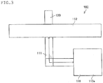
- a resonator 110 includes a resonator main body 110a, which has a predetermined volume, and a communication tube 111, which bifurcates from a suction passage 112 and allows the suction passage 112 to communicate with the resonator main body 110a, as shown in FIG. 3 , and a volume of the resonator main body 110a is so specified that noise at a frequency calculated based, for example, on Helmholtz's resonance theory is reduced.
- a side branch 120 is a tubular body with a bottomed part having a predetermined uniform cross section and bifurcates from the suction passage 112.
- a total length of the side branch 120 is specified as appropriate in accordance with a frequency of noise to be reduced.
- suction noise resulting from an air intermittent flow produced by suction of air when the suction valve is opened.
- the suction noise contains noise at a variety of frequencies, and to attenuate suction noise at a specific frequency that can be harsh noise, the volume of the resonator described above and the length of the side branch described above are adjusted as appropriate, and the thus adjusted resonator and side branch are disposed so as to bifurcate from the suction passage.
- a variety of forms of such a muffling apparatus have been known.
- the muffling apparatus described in Japanese Patent Laid-Open No. 11-294278 includes a plurality of mufflers, and among the plurality of mufflers, a first muffler has a resonant chamber the extends in a lengthwise direction of a suction passage and in a direction perpendicular to the lengthwise direction, and a second muffler is disposed in the resonant chamber and has an expansion chamber.
- a communication port of the suction passage in the resonant chamber and a communication port of the suction passage in the expansion chamber are arranged side by side along the lengthwise direction of the suction passage.
- At least a portion that forms the first muffler and includes the communication port of the suction passage in the resonant chamber, a portion that forms the second muffler and includes the communication port of the suction passage in the expansion chamber, and the suction passage are formed integrally with one another in integral molding.
- the muffling apparatus described in Japanese Patent Laid-Open No. 2008-133771 includes a resonant chamber formed of a space surrounded by not only a suction passage forming wall that forms part of a suction passage but a shielding wall that shields the space from the atmosphere, a Helmholtz-type muffler including a communication tube so provided that a communication tube that allows an interior of the suction passage to communicate with the resonant chamber is extended from the suction passage forming wall into the resonant chamber, and a side-branch-type muffler formed of a bottomed tubular wall that protrudes from the suction passage forming wall into the resonant chamber, and the muffling apparatus is formed of first, second, and third pieces formed separately from one another and then integrated with one another.
- the suction passage forming wall, a portion of the shielding wall, at least a portion of the communication tube, and a portion of the bottomed tubular wall are formed as the first piece, another portion different from the above-mentioned portion of the shielding wall, a portion other than the above-mentioned portion of the communication tube in the case where only the above-mentioned portion of the communication tube is formed as the first piece, and a portion other than the above-mentioned portion of the bottomed tubular wall are formed as the second piece, and a portion other than the above-mentioned portion of the shielding wall is formed as the third piece.
- the muffling apparatus described in Japanese Patent Laid-Open No. 2009-36185 is a muffling apparatus used with an internal combustion engine and including a hollow portion that forms a space that communicates with an interior of a suction/exhaust tube of the internal combustion engine and provides a muffling function based on resonance, and a volume varying device that makes a volume of the hollow portion variable is provided.
- holes are formed in an inner wall of the suction passage and at locations where the members bifurcate therefrom, undesirably resulting in air turbulence due to the holes. Since the air turbulence results in an increase in air-flow resistance, it is undesirably difficult to suppress the air-flow resistance.
- the present invention has been made in view of the problems described above, and an object of the present invention is to provide a muffling apparatus capable of sufficiently reducing noise, achieving space saving, and suppressing an increase in air-flow resistance in a suction passage.
- a muffling apparatus includes a resonator main body having a predetermined volume and a communication tube that allows the resonator main body to communicate with a suction passage of an internal combustion engine.
- the communication tube includes a first communication tube having one end that communicates with the suction passage, a second communication tube having one end that communicates with the resonator main body, and a continuous section that communicates with other ends of the first and second communication tubes, and a third communication tube is formed at the continuous section.
- the first and second communication tubes are preferably disposed so as to be perpendicular to each other via the continuous section.
- the third communication tube preferably extends in a direction opposite a direction in which the first communication tube extends.
- the muffling apparatus includes the continuous section, which communicates with the other ends of the first and second communication tubes, and the third communication tube is formed at the continuous section, whereby noise at a plurality of frequencies can be attenuated for sufficient reduction in noise, and an increase in air-flow resistance can be suppressed at the same time because it is not necessary to form a plurality of holes in the inner wall of the suction passage. Further, space saving is achieved.
- FIG. 1 describes an overview of a muffling apparatus according to the present embodiment.
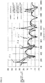
- FIG. 2 shows graphs for describing a muffling effect provided by the muffling apparatus according to the present embodiment.
- FIG. 3 describes an overview of a muffling apparatus of related art.
- a muffling apparatus 1 is attached to a suction passage 12 for introducing filtered outside air, which has undergone a filtering process in which an air cleaner that is not shown filters out dust and other undesirable objects contained in the outside air, into an internal combustion engine, as shown in FIG. 1 .
- the suction passage 12 is a tubular member so formed that an inner wall thereof is smoothened, and a variety of cross-sectional shapes of the suction passage 12 have been known, such as a circular shape, an elliptical shape, and a polygonal shape.
- the muffling apparatus 1 includes a resonator main body 11, which has a predetermined volume, and a communication tube 13, which allows the resonator main body 11 to communicate with the suction passage 12.
- the resonator main body 11 can be formed in any of a variety of shapes, such as a box-like shape and a cylindrical shape, and the volume of the resonator main body 11 is determined based on Helmholtz's resonance theory and in accordance with a frequency at which noise is attenuated.
- the communication tube 13 includes a first communication tube 14, which has one end that bifurcates from the suction passage 12, a second communication tube 15, which has one end that communicates with the resonator main body 11, and a continuous section 17, which is continuous with other ends of the first communication tube 14 and the second communication tube 15.
- the first communication tube 14 and the second communication tube 15 are disposed so as to be roughly perpendicular to each other via the continuous section 17.
- the communication tube 13 further includes a third communication tube 16, which is formed at the continuous section 17.
- the third communication tube 16 can extend in any direction as long as the third communication tube 16 is so formed as to be continuous with the continuous section 17.
- the third communication tube 16 preferably extends in a direction opposite a direction in which the first communication tube 14 extends.
- the communication tube 13 is a tubular member having a roughly fixed cross-sectional area that is formed to be smaller than the cross-sectional areas of the suction passage 12 and the resonator main body 11. Further, the first communication tube 14, the second communication tube 15, the third communication tube 16, and the continuous section 17 have roughly the same cross-sectional area and each have a smooth inner wall.
- the communication tube 13 and the resonator main body 11 may be made of any material and are preferably made, for example, of a synthetic resin.
- a synthetic resin for example, a polypropylene-based resin, a polyamide-based resin, or any other thermoplastic synthetic resin is preferably used.
- the communication tube 13 and the resonator main body 11 may be formed integrally with each other, or the communication tube 13 and the resonator main body 11 may be formed separately from each other and then combined with each other with a known joining device.
- the communication tube 13 the first communication tube 14, the second communication tube 15, the third communication tube 16, and the continuous section 17 may be formed integrally with one another, or these members may be formed separately from one another and then combined with one another as appropriate.
- the thus formed muffling apparatus 1 can muffle noise at first to third effect frequencies F1, F2, and F3, which can be derived from the following expression, where L1, L2, L3, and L4 (mm) represent the lengths of the first communication tube 14, the second communication tube 15, the third communication tube 16, and the continuous section 17.
- F 1 c 2 ⁇ S V ⁇ L 1 + L 2 + L 4
- F 2 c 2 L 1 + L 2 + L 4 + 3 L 3
- F 3 2 F 2
- c represents the sound speed (m/s) at room temperature
- S represents the cross-sectional area (mm 2 ) of the communication tube 13
- V represents the volume (L) of the resonator main body 11.
- the communication tube 13, which bifurcates from the suction passage 12 is a single communication tube, the number of holes formed in the inner wall of the suction passage 12 in association with the installation of the muffling apparatus 1 can be reduced, whereby an increase in air-flow resistance in association with an increase in the number of holes can be suppressed.
- an effect frequency F2' where the attenuation effect has been ascertained in Comparative Example 1 results from an effect of the communication tube of the resonator, and is therefore a secondary effect in addition to the purpose of reduction in noise at the effect frequency F1 provided by a design method of related art, and is an effect frequency that cannot be directly controlled.
- the muffling apparatus 1 according to the present embodiment can be so designed that the second effect frequency F2 is also a frequency where the noise is reduced.
- FIG. 2 shows comparison of the amount of attenuation among Example and Comparative Examples 1 to 3, and a greater the amount of attenuation along the vertical axis is taken to be a higher attenuation effect.
- Comparative Examples 1 to 3 described above were carried out as follows: In Comparative Example 1, the amount of attenuation in a form in which a resonator is attached to a suction passage via a communication tube is measured; in Comparative Example 2, the amount of attenuation in a form in which a side branch is attached to the suction passage is measured; and in Comparative Example 3, the amount of attenuation in a form in which only the suction passage is present is measured.
- the muffling apparatus 1 includes the continuous section, which communicates with the other ends of the first and second communication tubes, and the third communication tube is formed at the continuous section, whereby noise at a plurality of frequencies can be attenuated for sufficient reduction in noise, and space saving can be achieved at the same time. Further, an increase in air-flow resistance in the suction passage can be suppressed by suppression of the number of communication tubes that bifurcate from the suction passage.
- the present embodiment has been described with reference to the case where the third communication tube 16 is so formed as to extend in the direction opposite the direction in which the first communication tube 14 extends. Instead, the third communication tube 16 may be so formed as to extend in the direction opposite the direction in which the second communication tube 15 extends. It is apparent from the description of the claims that a form in which such a change or improvement is made also falls within the technical scope of the present invention.
Landscapes
- Engineering & Computer Science (AREA)
- Chemical & Material Sciences (AREA)
- Combustion & Propulsion (AREA)
- Mechanical Engineering (AREA)
- General Engineering & Computer Science (AREA)
- Exhaust Silencers (AREA)
- Soundproofing, Sound Blocking, And Sound Damping (AREA)
Abstract
There is provided a muffling apparatus capable of sufficiently reducing noise, achieving space saving, and suppressing an increase in air-flow resistance in a suction passage. In a muffling apparatus including a resonator main body having a predetermined volume and a communication tube that allows the resonator main body to communicate with a suction passage of an internal combustion engine, the communication tube includes a first communication tube having one end that communicates with the suction passage, a second communication tube having one end that communicates with the resonator main body, and a continuous section that communicates with other ends of the first and second communication tubes, and a third communication tube is formed at the continuous section.
Description
- The present invention relates to a muffling apparatus, and particularly to a muffling apparatus that is provided at a suction passage of an internal combustion engine and reduces suction noise.
- It is known that when an internal combustion engine is driven so that a suction valve opens and closes, pulsation noise is produced and forms suction noise. To reduce the suction noise, there is a known muffling apparatus having, for example, of a resonator or a side-branch-type resonator (hereinafter referred to as "side branch") so formed as to be continuous with the suction passage.
- A
resonator 110 includes a resonatormain body 110a, which has a predetermined volume, and acommunication tube 111, which bifurcates from asuction passage 112 and allows thesuction passage 112 to communicate with the resonatormain body 110a, as shown inFIG. 3 , and a volume of the resonatormain body 110a is so specified that noise at a frequency calculated based, for example, on Helmholtz's resonance theory is reduced. - A
side branch 120 is a tubular body with a bottomed part having a predetermined uniform cross section and bifurcates from thesuction passage 112. A total length of theside branch 120 is specified as appropriate in accordance with a frequency of noise to be reduced. - It is known that noise produced in the suction passage that communicates with an internal combustion engine is suction noise resulting from an air intermittent flow produced by suction of air when the suction valve is opened. The suction noise contains noise at a variety of frequencies, and to attenuate suction noise at a specific frequency that can be harsh noise, the volume of the resonator described above and the length of the side branch described above are adjusted as appropriate, and the thus adjusted resonator and side branch are disposed so as to bifurcate from the suction passage. A variety of forms of such a muffling apparatus have been known.
- The muffling apparatus described in Japanese Patent Laid-Open No.
11-294278 - The muffling apparatus described in Japanese Patent Laid-Open No.
2008-133771 - The muffling apparatus described in Japanese Patent Laid-Open No.
2009-36185 - According to the configurations of the muffling apparatus of related art described above, however, since a resonator and a side branch are both required so that a structure in which the resonator and the side branch bifurcate from the suction passage is employed, a space in which these members are disposed needs to be provided in the vicinity of the suction passage. Further, to attenuate noise at a specific frequency, it is necessary to ensure a certain volume of the resonator main body and a certain length of the side branch, undesirably resulting in an extreme difficulty in arranging these members in an engine room, which is required to be compact for space saving. Further, since the structure in which a plurality of members bifurcate from the suction passage is employed, holes are formed in an inner wall of the suction passage and at locations where the members bifurcate therefrom, undesirably resulting in air turbulence due to the holes. Since the air turbulence results in an increase in air-flow resistance, it is undesirably difficult to suppress the air-flow resistance.
- The present invention has been made in view of the problems described above, and an object of the present invention is to provide a muffling apparatus capable of sufficiently reducing noise, achieving space saving, and suppressing an increase in air-flow resistance in a suction passage.
- A muffling apparatus according to the present invention includes a resonator main body having a predetermined volume and a communication tube that allows the resonator main body to communicate with a suction passage of an internal combustion engine. The communication tube includes a first communication tube having one end that communicates with the suction passage, a second communication tube having one end that communicates with the resonator main body, and a continuous section that communicates with other ends of the first and second communication tubes, and a third communication tube is formed at the continuous section.
- In the muffling apparatus according to the present invention, the first and second communication tubes are preferably disposed so as to be perpendicular to each other via the continuous section.
- In the muffling apparatus according to the present invention, the third communication tube preferably extends in a direction opposite a direction in which the first communication tube extends.
- In the muffling apparatus according to the present invention, noise at least at a first effect frequency F1, a second effect frequency F2, and a third effect frequency F3, which are derived from a following expression, is preferably muffled, where L1 represents a length of the first communication tube, L2 represents a length of the second communication tube, L3 represents a length of the third communication tube, and L4 represents a length of the continuous section,

Expression 1, c represents a sound speed at room temperature, S represents a cross-sectional area of the communication tube, and V represents a volume of the resonator main body. - The above-mentioned summary of the present invention is not intended to list all features necessary for the present invention, and a sub-combination of a group of the features can also be a claim of the invention.
- The muffling apparatus according to the present invention includes the continuous section, which communicates with the other ends of the first and second communication tubes, and the third communication tube is formed at the continuous section, whereby noise at a plurality of frequencies can be attenuated for sufficient reduction in noise, and an increase in air-flow resistance can be suppressed at the same time because it is not necessary to form a plurality of holes in the inner wall of the suction passage. Further, space saving is achieved.
-
-
FIG. 1 is an overview of a muffling apparatus according to an embodiment of the present invention; -
FIG. 2 is graphs for describing a muffling effect provided by the muffling apparatus according to the present embodiment; and -
FIG. 3 is an overview of a muffling apparatus of related art. - A preferable embodiment for implementing the present invention will be described below with reference to the drawings. It is noted that the following embodiment is not intended to limit the invention according to each claim, and all combinations of features described in the embodiment are not necessarily essential for a solution of the present invention.
-
FIG. 1 describes an overview of a muffling apparatus according to the present embodiment.FIG. 2 shows graphs for describing a muffling effect provided by the muffling apparatus according to the present embodiment.FIG. 3 describes an overview of a muffling apparatus of related art. - A
muffling apparatus 1 according to the present embodiment is attached to asuction passage 12 for introducing filtered outside air, which has undergone a filtering process in which an air cleaner that is not shown filters out dust and other undesirable objects contained in the outside air, into an internal combustion engine, as shown inFIG. 1 . Thesuction passage 12 is a tubular member so formed that an inner wall thereof is smoothened, and a variety of cross-sectional shapes of thesuction passage 12 have been known, such as a circular shape, an elliptical shape, and a polygonal shape. - The
muffling apparatus 1 according to the present embodiment includes a resonatormain body 11, which has a predetermined volume, and acommunication tube 13, which allows the resonatormain body 11 to communicate with thesuction passage 12. The resonatormain body 11 can be formed in any of a variety of shapes, such as a box-like shape and a cylindrical shape, and the volume of the resonatormain body 11 is determined based on Helmholtz's resonance theory and in accordance with a frequency at which noise is attenuated. - The
communication tube 13 includes afirst communication tube 14, which has one end that bifurcates from thesuction passage 12, asecond communication tube 15, which has one end that communicates with the resonatormain body 11, and acontinuous section 17, which is continuous with other ends of thefirst communication tube 14 and thesecond communication tube 15. Thefirst communication tube 14 and thesecond communication tube 15 are disposed so as to be roughly perpendicular to each other via thecontinuous section 17. - The
communication tube 13 further includes athird communication tube 16, which is formed at thecontinuous section 17. Thethird communication tube 16 can extend in any direction as long as thethird communication tube 16 is so formed as to be continuous with thecontinuous section 17. For example, thethird communication tube 16 preferably extends in a direction opposite a direction in which thefirst communication tube 14 extends. - The
communication tube 13 is a tubular member having a roughly fixed cross-sectional area that is formed to be smaller than the cross-sectional areas of thesuction passage 12 and the resonatormain body 11. Further, thefirst communication tube 14, thesecond communication tube 15, thethird communication tube 16, and thecontinuous section 17 have roughly the same cross-sectional area and each have a smooth inner wall. - The
communication tube 13 and the resonatormain body 11 may be made of any material and are preferably made, for example, of a synthetic resin. For example, a polypropylene-based resin, a polyamide-based resin, or any other thermoplastic synthetic resin is preferably used. Further, thecommunication tube 13 and the resonatormain body 11 may be formed integrally with each other, or thecommunication tube 13 and the resonatormain body 11 may be formed separately from each other and then combined with each other with a known joining device. Similarly, as for thecommunication tube 13, thefirst communication tube 14, thesecond communication tube 15, thethird communication tube 16, and thecontinuous section 17 may be formed integrally with one another, or these members may be formed separately from one another and then combined with one another as appropriate. - The thus formed
muffling apparatus 1 according to the present embodiment can muffle noise at first to third effect frequencies F1, F2, and F3, which can be derived from the following expression, where L1, L2, L3, and L4 (mm) represent the lengths of thefirst communication tube 14, thesecond communication tube 15, thethird communication tube 16, and thecontinuous section 17.
- In
Expression 2, c represents the sound speed (m/s) at room temperature, S represents the cross-sectional area (mm2) of thecommunication tube 13, and V represents the volume (L) of the resonatormain body 11. - In the
muffling apparatus 1 according to the present embodiment, since thecommunication tube 13, which bifurcates from thesuction passage 12 is a single communication tube, the number of holes formed in the inner wall of thesuction passage 12 in association with the installation of themuffling apparatus 1 can be reduced, whereby an increase in air-flow resistance in association with an increase in the number of holes can be suppressed. - In comparison of the amount of attenuation in Example of the
muffling apparatus 1 according to the present embodiment with the amount of attenuation in Comparative Examples 1 to 3 having the configurations of related art, significant amounts of attenuation of noise can be ascertained at the first effect frequency F1, where attenuation is also achieved in Comparative Example 1, as well as at the second and third effect frequencies F2, F3, as shown inFIG. 2 . The first to third effect frequencies F1, F2, and F3 can be adjusted as appropriate by using the expression described above. - In contrast, an effect frequency F2', where the attenuation effect has been ascertained in Comparative Example 1, results from an effect of the communication tube of the resonator, and is therefore a secondary effect in addition to the purpose of reduction in noise at the effect frequency F1 provided by a design method of related art, and is an effect frequency that cannot be directly controlled. On the other hand, the
muffling apparatus 1 according to the present embodiment can be so designed that the second effect frequency F2 is also a frequency where the noise is reduced. Further,FIG. 2 shows comparison of the amount of attenuation among Example and Comparative Examples 1 to 3, and a greater the amount of attenuation along the vertical axis is taken to be a higher attenuation effect. - Comparative Examples 1 to 3 described above were carried out as follows: In Comparative Example 1, the amount of attenuation in a form in which a resonator is attached to a suction passage via a communication tube is measured; in Comparative Example 2, the amount of attenuation in a form in which a side branch is attached to the suction passage is measured; and in Comparative Example 3, the amount of attenuation in a form in which only the suction passage is present is measured.
- As described above, the
muffling apparatus 1 according to the present embodiment includes the continuous section, which communicates with the other ends of the first and second communication tubes, and the third communication tube is formed at the continuous section, whereby noise at a plurality of frequencies can be attenuated for sufficient reduction in noise, and space saving can be achieved at the same time. Further, an increase in air-flow resistance in the suction passage can be suppressed by suppression of the number of communication tubes that bifurcate from the suction passage. - The present embodiment has been described with reference to the case where the
third communication tube 16 is so formed as to extend in the direction opposite the direction in which thefirst communication tube 14 extends. Instead, thethird communication tube 16 may be so formed as to extend in the direction opposite the direction in which thesecond communication tube 15 extends. It is apparent from the description of the claims that a form in which such a change or improvement is made also falls within the technical scope of the present invention. - The invention may be embodied in other specific forms without departing from the spirit or essential characteristics thereof. The present embodiments are therefore to be considered in all respects as illustrative and not restrictive, the scope of the invention being indicated by the appended claims rather than by the foregoing description and all changes which come within the meaning and range of equivalency of the claims are therefore intended to be embraced therein.
- The entire disclosure of Japanese Patent Application No.
2016-225180 filed on November 18, 2016 -
- 1 Muffling apparatus, 11, 110a Resonator main body, 12, 112 Suction passage, 13, 111 Communication tube, 14 First communication tube, 15 Second communication tube, 16 Third communication tube, 17 Continuous section, 110 Resonator, 120 Side branch
Claims (4)
- A muffling apparatus comprising:a resonator main body having a predetermined volume; anda communication tube that allows the resonator main body to communicate with a suction passage of an internal combustion engine,wherein the communication tube includes a first communication tube having one end that communicates with the suction passage, a second communication tube having one end that communicates with the resonator main body, and a continuous section that communicates with other ends of the first and second communication tubes, anda third communication tube is formed at the continuous section.
- The muffling apparatus according to claim 1,
wherein the first and second communication tubes are disposed so as to be perpendicular to each other via the continuous section. - The muffling apparatus according to claim 1 or 2,
wherein the third communication tube extends in a direction opposite a direction in which the first communication tube extends. - The muffling apparatus according to any one of claims 1 to 3,
wherein noise at least at a first effect frequency F1, a second effect frequency F2, and a third effect frequency F3, which are derived from a following expression, is muffled, where L1 represents a length of the first communication tube, L2 represents a length of the second communication tube, L3 represents a length of the third communication tube, and L4 represents a length of the continuous section,
Applications Claiming Priority (1)
| Application Number | Priority Date | Filing Date | Title |
|---|---|---|---|
| JP2016225180A JP2018080685A (en) | 2016-11-18 | 2016-11-18 | Silencer |
Publications (1)
| Publication Number | Publication Date |
|---|---|
| EP3324034A1 true EP3324034A1 (en) | 2018-05-23 |
Family
ID=60083129
Family Applications (1)
| Application Number | Title | Priority Date | Filing Date |
|---|---|---|---|
| EP17195874.7A Withdrawn EP3324034A1 (en) | 2016-11-18 | 2017-10-11 | Muffling apparatus |
Country Status (3)
| Country | Link |
|---|---|
| US (1) | US20180142652A1 (en) |
| EP (1) | EP3324034A1 (en) |
| JP (1) | JP2018080685A (en) |
Families Citing this family (3)
| Publication number | Priority date | Publication date | Assignee | Title |
|---|---|---|---|---|
| JP2019143478A (en) * | 2018-02-15 | 2019-08-29 | 株式会社Roki | Noise suppressor |
| KR102415416B1 (en) * | 2020-10-28 | 2022-07-01 | 재단법인 파동에너지 극한제어 연구단 | Metamaterial muffler using fractal structure |
| CN114470474B (en) * | 2021-12-30 | 2024-12-31 | 深圳小梦智眠科技有限公司 | Low noise control box of functional pillow and functional pillow |
Citations (7)
| Publication number | Priority date | Publication date | Assignee | Title |
|---|---|---|---|---|
| JPH11294278A (en) | 1998-04-13 | 1999-10-26 | Honda Motor Co Ltd | Intake silencer |
| US20070044747A1 (en) * | 2005-08-26 | 2007-03-01 | Toyoda Gosei Co., Ltd. | Air intake sound control structure |
| JP2008133771A (en) | 2006-11-28 | 2008-06-12 | Kojima Press Co Ltd | Muffling device |
| JP2009036185A (en) | 2007-08-04 | 2009-02-19 | Nissan Motor Co Ltd | Silencer for internal combustion engine |
| DE102012019318A1 (en) * | 2012-10-02 | 2014-04-03 | Mann + Hummel Gmbh | Silencer for gas-carrying pipe in internal combustion engine, has primary acoustic portions and secondary acoustic portions which are connected through common connecting elements connected to gas-conducting pipe |
| US20160123208A1 (en) * | 2014-11-02 | 2016-05-05 | Mann+Hummel Gmbh | Air induction system having an acoustic resonator |
| EP3112654A1 (en) * | 2015-07-03 | 2017-01-04 | Mann+Hummel GmbH | Adapter of an acoustic system of a gas-ducting system, acoustic system and gas-ducting system with an acoustic system |
Family Cites Families (17)
| Publication number | Priority date | Publication date | Assignee | Title |
|---|---|---|---|---|
| US1910672A (en) * | 1932-05-13 | 1933-05-23 | Maxim Silencer Co | Acoustic wave filter |
| US2297046A (en) * | 1939-08-25 | 1942-09-29 | Maxim Silencer Co | Means for preventing shock excitation of acoustic conduits or chambers |
| HU207375B (en) * | 1987-02-12 | 1993-03-29 | Autoipari Kutato Fejlesztoe | Internal combustion piston engine |
| JPH0819885B2 (en) * | 1988-12-28 | 1996-03-04 | マツダ株式会社 | Engine intake system |
| JPH09126074A (en) * | 1995-10-31 | 1997-05-13 | Tenetsukusu:Kk | Branched type tube resonator |
| GB9522724D0 (en) * | 1995-11-06 | 1996-01-10 | Acts Ltd | A noise attenuator for an induction system or an exhaust system |
| JPH10187162A (en) * | 1996-12-26 | 1998-07-14 | Inoac Corp | Resonator |
| JP4189529B2 (en) * | 2002-08-07 | 2008-12-03 | 川崎重工業株式会社 | Exhaust outlet device for small vessels |
| US6814041B1 (en) * | 2003-01-31 | 2004-11-09 | Fleetguard, Inc. | Multi-frequency engine intake resonator |
| DE102004038216A1 (en) * | 2004-08-05 | 2006-03-16 | Mann+Hummel Gmbh | intake silencer |
| US7364012B2 (en) * | 2005-08-05 | 2008-04-29 | Delphi Technologies, Inc. | Dual-neck plane wave resonator |
| JP2008309050A (en) * | 2007-06-14 | 2008-12-25 | Mahle Filter Systems Japan Corp | Resonator |
| JP5326946B2 (en) * | 2008-09-02 | 2013-10-30 | ヤマハ株式会社 | Acoustic structure and acoustic chamber |
| US8591208B2 (en) * | 2009-06-24 | 2013-11-26 | Southwest Research Institute | Multi-frequency pulsation absorber at cylinder valve cap |
| US8393437B2 (en) * | 2011-02-15 | 2013-03-12 | Westinghouse Electric Company Llc | Noise and vibration mitigation system for nuclear reactors employing an acoustic side branch resonator |
| US20180174566A1 (en) * | 2016-12-19 | 2018-06-21 | Caterpillar Inc. | Compact acoustic resonator for enclosed systems |
| JP2019143478A (en) * | 2018-02-15 | 2019-08-29 | 株式会社Roki | Noise suppressor |
-
2016
- 2016-11-18 JP JP2016225180A patent/JP2018080685A/en active Pending
-
2017
- 2017-10-03 US US15/723,533 patent/US20180142652A1/en not_active Abandoned
- 2017-10-11 EP EP17195874.7A patent/EP3324034A1/en not_active Withdrawn
Patent Citations (7)
| Publication number | Priority date | Publication date | Assignee | Title |
|---|---|---|---|---|
| JPH11294278A (en) | 1998-04-13 | 1999-10-26 | Honda Motor Co Ltd | Intake silencer |
| US20070044747A1 (en) * | 2005-08-26 | 2007-03-01 | Toyoda Gosei Co., Ltd. | Air intake sound control structure |
| JP2008133771A (en) | 2006-11-28 | 2008-06-12 | Kojima Press Co Ltd | Muffling device |
| JP2009036185A (en) | 2007-08-04 | 2009-02-19 | Nissan Motor Co Ltd | Silencer for internal combustion engine |
| DE102012019318A1 (en) * | 2012-10-02 | 2014-04-03 | Mann + Hummel Gmbh | Silencer for gas-carrying pipe in internal combustion engine, has primary acoustic portions and secondary acoustic portions which are connected through common connecting elements connected to gas-conducting pipe |
| US20160123208A1 (en) * | 2014-11-02 | 2016-05-05 | Mann+Hummel Gmbh | Air induction system having an acoustic resonator |
| EP3112654A1 (en) * | 2015-07-03 | 2017-01-04 | Mann+Hummel GmbH | Adapter of an acoustic system of a gas-ducting system, acoustic system and gas-ducting system with an acoustic system |
Also Published As
| Publication number | Publication date |
|---|---|
| JP2018080685A (en) | 2018-05-24 |
| US20180142652A1 (en) | 2018-05-24 |
Similar Documents
| Publication | Publication Date | Title |
|---|---|---|
| US7556123B2 (en) | Muffler duct | |
| KR950003732B1 (en) | Silencer for Automobile Exhaust System | |
| EP2384401B1 (en) | Broadband silencer | |
| US20190249580A1 (en) | Muffling apparatus | |
| EP3324034A1 (en) | Muffling apparatus | |
| US20160334131A1 (en) | Resonator and air flow pipe having resonator | |
| US8820475B2 (en) | Exhaust muffler | |
| US20040007197A1 (en) | Multi-chamber resonator | |
| US9737840B2 (en) | Air cleaner | |
| KR20170025675A (en) | Resonator for vehicle | |
| JP2020026748A (en) | Silencer | |
| KR20140003256A (en) | Intake system for high frequency noise of automobile | |
| CN107314186B (en) | Air duct with muffler | |
| CN207420668U (en) | Silencer and with its vehicle | |
| EP3711841A1 (en) | Air filtration device | |
| CN108026872A (en) | The device of decay induction noise and radiated noise | |
| US5025889A (en) | Engine noise reducer | |
| JP6646033B2 (en) | Silencer | |
| US20120055169A1 (en) | Turbine engine comprising an exhaust-gas guide cone with a sound suppressor | |
| CN112443433B (en) | air filtration device | |
| CN209129709U (en) | Multitube is got lost structure exhaust silencer | |
| US5162621A (en) | Internal sidebranch resonator | |
| JP2011017291A (en) | Air suction device | |
| US10876504B2 (en) | Silencer having expansion chamber and partition | |
| ITMI20010873A1 (en) | LOW NOISE AIR FILTERING DEVICE |
Legal Events
| Date | Code | Title | Description |
|---|---|---|---|
| PUAI | Public reference made under article 153(3) epc to a published international application that has entered the european phase |
Free format text: ORIGINAL CODE: 0009012 |
|
| AK | Designated contracting states |
Kind code of ref document: A1 Designated state(s): AL AT BE BG CH CY CZ DE DK EE ES FI FR GB GR HR HU IE IS IT LI LT LU LV MC MK MT NL NO PL PT RO RS SE SI SK SM TR |
|
| AX | Request for extension of the european patent |
Extension state: BA ME |
|
| STAA | Information on the status of an ep patent application or granted ep patent |
Free format text: STATUS: THE APPLICATION IS DEEMED TO BE WITHDRAWN |
|
| 18D | Application deemed to be withdrawn |
Effective date: 20181124 |