EP3324018A1 - Integrated calcination-carbonation system and closed-loop co2 cycle for thermochemical energy storage and electrical energy generation - Google Patents
Integrated calcination-carbonation system and closed-loop co2 cycle for thermochemical energy storage and electrical energy generation Download PDFInfo
- Publication number
- EP3324018A1 EP3324018A1 EP16817295.5A EP16817295A EP3324018A1 EP 3324018 A1 EP3324018 A1 EP 3324018A1 EP 16817295 A EP16817295 A EP 16817295A EP 3324018 A1 EP3324018 A1 EP 3324018A1
- Authority
- EP
- European Patent Office
- Prior art keywords
- carbonation
- calcination
- cycle
- integrated
- energy
- Prior art date
- Legal status (The legal status is an assumption and is not a legal conclusion. Google has not performed a legal analysis and makes no representation as to the accuracy of the status listed.)
- Ceased
Links
Images





Classifications
-
- F—MECHANICAL ENGINEERING; LIGHTING; HEATING; WEAPONS; BLASTING
- F02—COMBUSTION ENGINES; HOT-GAS OR COMBUSTION-PRODUCT ENGINE PLANTS
- F02C—GAS-TURBINE PLANTS; AIR INTAKES FOR JET-PROPULSION PLANTS; CONTROLLING FUEL SUPPLY IN AIR-BREATHING JET-PROPULSION PLANTS
- F02C1/00—Gas-turbine plants characterised by the use of hot gases or unheated pressurised gases, as the working fluid
-
- F—MECHANICAL ENGINEERING; LIGHTING; HEATING; WEAPONS; BLASTING
- F02—COMBUSTION ENGINES; HOT-GAS OR COMBUSTION-PRODUCT ENGINE PLANTS
- F02C—GAS-TURBINE PLANTS; AIR INTAKES FOR JET-PROPULSION PLANTS; CONTROLLING FUEL SUPPLY IN AIR-BREATHING JET-PROPULSION PLANTS
- F02C6/00—Plural gas-turbine plants; Combinations of gas-turbine plants with other apparatus; Adaptations of gas-turbine plants for special use
- F02C6/14—Gas-turbine plants having means for storing energy, e.g. for meeting peak loads
-
- C—CHEMISTRY; METALLURGY
- C01—INORGANIC CHEMISTRY
- C01B—NON-METALLIC ELEMENTS; COMPOUNDS THEREOF; METALLOIDS OR COMPOUNDS THEREOF NOT COVERED BY SUBCLASS C01C
- C01B32/00—Carbon; Compounds thereof
- C01B32/50—Carbon dioxide
-
- C—CHEMISTRY; METALLURGY
- C01—INORGANIC CHEMISTRY
- C01F—COMPOUNDS OF THE METALS BERYLLIUM, MAGNESIUM, ALUMINIUM, CALCIUM, STRONTIUM, BARIUM, RADIUM, THORIUM, OR OF THE RARE-EARTH METALS
- C01F11/00—Compounds of calcium, strontium, or barium
- C01F11/02—Oxides or hydroxides
- C01F11/04—Oxides or hydroxides by thermal decomposition
-
- C—CHEMISTRY; METALLURGY
- C01—INORGANIC CHEMISTRY
- C01F—COMPOUNDS OF THE METALS BERYLLIUM, MAGNESIUM, ALUMINIUM, CALCIUM, STRONTIUM, BARIUM, RADIUM, THORIUM, OR OF THE RARE-EARTH METALS
- C01F11/00—Compounds of calcium, strontium, or barium
- C01F11/02—Oxides or hydroxides
- C01F11/04—Oxides or hydroxides by thermal decomposition
- C01F11/06—Oxides or hydroxides by thermal decomposition of carbonates
-
- C—CHEMISTRY; METALLURGY
- C01—INORGANIC CHEMISTRY
- C01F—COMPOUNDS OF THE METALS BERYLLIUM, MAGNESIUM, ALUMINIUM, CALCIUM, STRONTIUM, BARIUM, RADIUM, THORIUM, OR OF THE RARE-EARTH METALS
- C01F11/00—Compounds of calcium, strontium, or barium
- C01F11/18—Carbonates
-
- F—MECHANICAL ENGINEERING; LIGHTING; HEATING; WEAPONS; BLASTING
- F02—COMBUSTION ENGINES; HOT-GAS OR COMBUSTION-PRODUCT ENGINE PLANTS
- F02C—GAS-TURBINE PLANTS; AIR INTAKES FOR JET-PROPULSION PLANTS; CONTROLLING FUEL SUPPLY IN AIR-BREATHING JET-PROPULSION PLANTS
- F02C1/00—Gas-turbine plants characterised by the use of hot gases or unheated pressurised gases, as the working fluid
- F02C1/04—Gas-turbine plants characterised by the use of hot gases or unheated pressurised gases, as the working fluid the working fluid being heated indirectly
- F02C1/10—Closed cycles
Definitions
- the invention falls under the technical field of technologies aimed at energy storage, more specifically relating to thermochemical energy storage and the integration thereof with energy generation technologies from medium and high temperature heat sources.
- Energy storage is one of the fields of research with the greatest potential for growth at a global level, driven among other factors, by the need to achieve an improved integration of renewable generation technologies, the improvement of the capacity to decouple production and energy demand being fundamental for the development of these technologies.
- Another widely studied storage system consists in taking advantage of the latent heat of materials that undergo phase changes, generally between solid and liquid [2].
- thermochemical storage which has recently acquired significant prominence, consisting of decoupling production and demand by means of chemical compounds.
- the heat obtained from an external source is used to bring about an endothermic reaction, the products of which will be stored until the moment of energy demand, in which, by means of the inverse (reversible) exothermic reaction, they release the stored heat making it available for use in thermal generation systems.
- thermochemical storage is the greater energy density that these compounds usually have when compared to the components used in phase change storage or by means of sensible heat [1], [2].
- Chemical storage technology is in an initial research stage, so the capacity for development thereof is enormous, given the great storage potential of this technology and the increase in plants that require solving the problem of discontinuous production and production dependent on external environmental factors.
- the basic operations of the cycle start with the decomposition of the CaCO 3 in the calcination reactor (calciner) producing CaO and CO2, which needs a large energy contribution given the high energy density of calcium carbonate.
- the products are obtained and the energy that these contain is recovered, they are stored until the subsequent use thereof.
- the possible thermal storage time will depend largely on the conditions of the storage itself and on the energy demand, which may be weeks or even months [4]. In renewable energy plants, especially those based on solar energy, the typical storage time will be hours (during the night) or days (in periods of low solar radiation).
- the components are taken separately to the carbonation reactor (carbonator), where, by means of the inverse reaction, the energy stored in chemical form will be released.
- the present invention envisages the development of a thermochemical storage system based on calcium looping together with a closed cycle through which CO 2 or mixtures of CO 2 gases evolve, for power generation.
- the assembly achieves significant energy storage performance, in terms of the yields achieved-values above 46% depending on the implemented configuration, as described below, as well as in terms of the use of widely available and cheap materials and the possibility of storing energy during extended periods.
- the proposed system optimizes the energy efficiency capacities of both systems integrated by the configuration of the elements that make it up and the combination of operating parameters that it enables associated to both systems.
- pure CO 2 or even mixtures of CO 2 with other gases can evolve, among which are Nitrogen, Helium, air, steam, not excluding other gases or combinations that are not mentioned.
- the invention presented in this patent can be applied as an energy storage system in any application with heat available at medium temperature at the inlet of the calciner, being useful among other applications, and not excluding others that are not mentioned, for solar plants, energy recovery systems or industrial processes.
- CaL Calcium looping
- the invention that is presented integrates closed cycles of CO 2 or gas mixtures with CO 2 for generating electric power in combination with thermochemical energy storage from calcium looping (CaL).
- the present invention relates to a thermochemical energy storage system applicable to systems with heat available at medium/high temperature based on the joint use of a thermochemical storage system according to the calcium looping cycle and a power loop for closed-cycle power generation where CO 2 or mixtures of gases with CO 2 evolve.
- the overall net yield reaches values above 46%. This yield is defined as the relationship between the energy obtained in the complete cycle (minus the consumption of the plant) and the energy input in the calciner.
- pure CO 2 or mixtures of CO 2 with other gases can evolve, among which are Nitrogen, Helium, air, steam, not excluding other gases or combinations thereof that are not mentioned.
- the proposed energy storage system is made up of two subsystems, one associated to the calcination/carbonation cycle (Calcium Looping) and another to a closed cycle of CO 2 , having a series of heat exchangers that link both subsystems, such that the recovery of heat is maximized, as well as the adjustment of the operating parameters and the benefits obtained from the joint operation of both systems in the power generation mode.
- Both systems converge between two fluidized bed reactors, where the carbonation and the calcination of the sorbent takes place in two temporally differentiated storage and generation phases.
- the endothermic reaction of the formation of CaO and CO 2 from CaCO 3 with external heat input is produced in the calciner.
- the energy from the thermal source at medium temperature (higher than 550°C) is used to carry out the endothermic reaction and both products (CaO and CO 2 ) are stored for the subsequent use thereof in the production of electric power in the unloading phase in the coupled power cycle.
- the system Given the characteristic of the products, the system can decouple storage and generation for long periods of time. In the generation phase, CO 2 and CaO react by means of exothermic reaction.
- This invention proposes the integration of a cycle in closed power loop on the carbonator side through which it evolves CO 2 or mixtures of CO 2 and gases.
- the heat generated in the carbonation reaction is transmitted to the CaCO 3 formed and the stream of CO 2 , or mixture of CO 2 with other gases, which does not participate in the carbonation reaction.
- the amount of CO 2 that does not react varies depending on the loss of CaO activity based on the number of carbonation cycles to which it is submitted.
- the gas stream whether made of pure CO 2 or CO 2 with other gases, at high pressure and temperature, evolves through the closed cycle of the power loop for the production of electric power. It has two possible variants:
- the CO 2 /gas loop is closed by deriving it to a storage system thereof (independent from the functional point of view of the storage for calcium looping). In the case of the direct configuration, it will need compression in order to close the cycle after the expansion in the turbine.
- the integration of the power loop proposed in the carbonator of the calcium looping cycle enables an energy recovery process that maximizes the relationship between the energy obtained in the power cycle and the energy recovery between the power cycle and the calcium looping through an assembly of heat exchangers and divisions of the flows.
- This integration enables optimizing the required operation and parameters both in the inbound CaO and CO 2 streams and existing processes, as well as in the carbonator and in the electric generation operation.
- the CO 2 that does not react in the carbonation evolves in a closed cycle for the production of power and for heating other streams of the integrated system based on the thermal and/or electric demand of the plant, by means of the optimized management of the flows that evolve through the different systems of exchangers and the amount of flow that evolves through the power loop regulated by means of the storage systems specific to the power loop.
- the operating parameters of the heat generation assembly are adjusted in the carbonator and in the power generation system, optimizing the operation of the assembly.
- the mass flow rate that evolves through the power loop is controlled.
- the thermal generation is controlled by acting on the values of the mass flow rates and flow temperatures as well as the pressure in the carbonator.
- pure CO 2 or mixtures of CO 2 with other fluids can evolve such as: N2, He, Air, Steam, among others, and not excluding those not mentioned.
- the configuration of the system and the optimal parameters thereof vary based on the application of the presented concept and the required power levels.
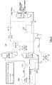
- Figures 1 , 2 and 3 show three direct integration diagrams of the calcium looping assembly with a power loop integrated in the carbonator.
- Figures 4 , 5 and 6 show three direct integration diagrams of the calcium looping assembly with a power loop integrated in the carbonator.
- the mass flow rate of CO 2 evolves from the carbonator outlet in the direction of the gas turbine where it expands, generating electricity.
- Figure 1 shows a direct integration with heat recovery in HXF for heating the stream of CaO with the outlet stream of the power loop turbine and with HXE for recovering heat from the stream of CaCO 3 that comes out of the carbonator.
- an additional HXG heat exchange train is added to the configuration shown in Figure 1 and the gas stream is divided, different fractions of mass flow rate evolving for heating the streams associated to the calcium looping based on the flow rates that evolve and the temperature levels required under different operating conditions of CaO (in the HXF exchanger) and CO 2 (HFG exchanger).
- the heat available for these streams and the fractions derived towards each exchanger are dependent on the total flow rate that evolves through the turbine and the level of expansion reached therein.
- Both parameters are controlled by controlling the pressure in the carbonator, the feed pressure of the flow of the power loop from the storage/regulation system and controlling the mass flow rate circulating in the power loop by means of the contribution or extraction of part of the flow rate from the storage system. All of these parameters are adjusted based on the operating requirements in the generation mode.
- the two streams that have evolved towards the HXF and HXG exchangers combine again in order to evolve by closing the power loop.
- the storage/regulation system of the power loop enables storage in the loading phase and enables regulating the flow rate circulating through the power loop, by injecting or extracting flow rate for which it has a compression system for the filling thereof and an expansion system for injecting flow rate into the system.
- a cooling system is optionally incorporated.
- the flow proceeding from the power loop joins the flow of CO 2 from the energy storage system of the calcium looping.
- This CO 2 stored from the Calcium Looping system expands in a turbo-compressor group that generates electric power in addition to that obtained in the main turbine.
- an added exchange system is added to the one presented in the configuration proposed in Figure 2 .
- the stream of CO 2 proceeding from the storage of the calcium looping and the stream proceeding from the power loop join together and evolve through a train of parallel exchangers (HXG and HXI), which optimizes the heat recovery process at a low temperature for the stream of CO 2 entering the carbonator.
- HXE high-temperature heat of the stream of CaCO 3 is recovered in the final preheating phase of the flow of CO 2 entering the carbonator.
- This assembly of exchangers ensures reaching the required temperatures with a high level of heat recovery.
- an assembly of heat exchangers recovers heat for the CO 2 that evolves in the direction of the carbonator from the stream of CaCO 3 coming out of it.
- the configuration of the power loop and the arrangement of the heat recovery system between streams presented by the invention optimizes the heat recovery process between streams and maximizes the efficiency of the assembly in the generation phase.
- a heat exchange arrangement is considered between the stream of CaCO 3 and CO 2 generated in the calciner with a division of the flow of CaCO 3 into two streams towards an assembly of parallel exchangers where the stream of CO 2 is cooled and a portion of the flow of CaCO 3 is heated (HXB), and another exchanger where a portion of the CaCO 3 is heated by the flow of CaO coming out of the calciner (HXA).
- the cooled CO 2 is subjected to an additional refrigerated compression process in several stages for the storage thereof and subsequent use in the unloading phase.
- thermochemical energy storage and electric power generation system of the present invention where the power loop in a closed cycle of CO 2 or mixture of CO 2 with other gases is integrated into the carbonator.
- thermochemical energy storage and electric power generation system of the present invention Another aspect is the integrated thermochemical energy storage and electric power generation system of the present invention, wherein carbonation is carried out at a pressure of CO 2 between 1 and 12 bars.
- thermochemical energy storage and electric power generation system of the present invention wherein calcination is carried out at a temperature between 675 and 950°C and carbonation is carried out at a temperature between 850 and 950°C.
- the parameters that have been taken are: Net power absorbed in the calciner 100 MW Temperature in the carbonator 875 °C Average reactivity of the CaO in the carbonator 0.30 - Heat loss in the carbonator 10 % Ambient temperature 20 °C Minimum temperature difference of solid-solid exchange 20 °C Minimum temperature difference of gas-gas exchange 15 °C Minimum temperature difference of gas-solid exchange 10 °C Energy consumption associated to the transportation of solids 5 MJ/ton/100 m Estimated equivalent transportation distance 200 m Isentropic efficiency in the turbine 0.89 - CO 2 storage pressure 75 bar
- the efficiency of the cycle depends on the balance between the power produced in the gas turbine and the resulting power consumption in the system (mounted on a shaft) made up of the turbine and the CO 2 compressor. This is because the power required for the compression of the CO 2 before the storage on the side of the calciner does not influence the balance in the area of the carbonator, thus maintaining it constant throughout the parametric analyses carried out.
- the conditions in which the calcination-carbonation cycles are integrated with a power loop in a closed cycle of CO 2 comprise carbonation at high partial pressure of CO 2 , at high temperature. Furthermore, it is desirable that the calcination be carried out at the lowest possible temperature in order to use solar receptors based on metallic alloys available on the market.
- the multicycle behavior of natural limestone was measured by means of thermogravimetry ( B. Sarrion, J. M. Valverde, A. Perejon, L. A. Perez-Maqueda, P. E. Sanchez-Jimenez. On the multicycle activity of natural limestone/dolomite for cheap, efficient and non-toxic Thermochemical Energy Storage of Concentrated Solar Power. Energy Technology. doi.
- Figure 9 - Conversion of CaO derived from limestone obtained by thermogravimetrical analysis (adapted from B. Sarrion, J. M. Valverde, A. Perejon, L. A. Perez-Maqueda, P. E. Sanchez-Jimenez. On the multicycle activity of natural limestone/dolomite for cheap, efficient and non-toxic Thermochemical Energy Storage of Concentrated Solar Power. Energy Technology, doi. 10.1002/ente.201600068 ; article in press (not published)).
- the squares represent the results of calcination-carbonation cycles with optimal operating conditions for the storage of concentrated solar energy according to the present application: carbonation at 850°C in an atmosphere of pure CO 2 and calcination at 700°C in an atmosphere of pure He.
- the figure shows the results obtained at these conditions based on the number of cycles N.
- the triangles represent the results of calcination-carbonation cycles in conditions for capturing CO 2 : carbonation at 650°C in an atmosphere of 15% CO 2 /85% air (volume/volume) and calcination at 950°C in an atmosphere of 70% CO 2 /30% air (volume/volume).
Landscapes
- Chemical & Material Sciences (AREA)
- Organic Chemistry (AREA)
- Engineering & Computer Science (AREA)
- Inorganic Chemistry (AREA)
- Life Sciences & Earth Sciences (AREA)
- Geology (AREA)
- Mechanical Engineering (AREA)
- General Engineering & Computer Science (AREA)
- Combustion & Propulsion (AREA)
- Thermal Sciences (AREA)
- Physics & Mathematics (AREA)
- Chemical Kinetics & Catalysis (AREA)
- Engine Equipment That Uses Special Cycles (AREA)
- Solid-Sorbent Or Filter-Aiding Compositions (AREA)
Abstract
Description
- The invention falls under the technical field of technologies aimed at energy storage, more specifically relating to thermochemical energy storage and the integration thereof with energy generation technologies from medium and high temperature heat sources.
- Energy storage is one of the fields of research with the greatest potential for growth at a global level, driven among other factors, by the need to achieve an improved integration of renewable generation technologies, the improvement of the capacity to decouple production and energy demand being fundamental for the development of these technologies.
- To this end, a large number of thermal storage technologies have been researched in recent years, with systems based on sensitive heat storage being the most developed at an industrial level [1]. These systems generally use molten salts, mineral oils or ceramic materials as a means of storage.
- Another widely studied storage system consists in taking advantage of the latent heat of materials that undergo phase changes, generally between solid and liquid [2].
- A third possibility is thermochemical storage, which has recently acquired significant prominence, consisting of decoupling production and demand by means of chemical compounds. The heat obtained from an external source is used to bring about an endothermic reaction, the products of which will be stored until the moment of energy demand, in which, by means of the inverse (reversible) exothermic reaction, they release the stored heat making it available for use in thermal generation systems.
- The main advantage of thermochemical storage is the greater energy density that these compounds usually have when compared to the components used in phase change storage or by means of sensible heat [1], [2].
- Chemical storage technology is in an initial research stage, so the capacity for development thereof is enormous, given the great storage potential of this technology and the increase in plants that require solving the problem of discontinuous production and production dependent on external environmental factors.
- From among the technologies intended for large-scale energy storage by means of thermochemical storage, one of the most promising is the carbonation-calcination cycle, normally called calcium looping (CaL) [3], [4].
- Calcium looping (CaL) is a process based on the reversible reaction between calcium oxide and carbon dioxide to produce calcium carbonate:
CaO(s) + CO2(g) ↔CaCO3(s)

- The basic operations of the cycle start with the decomposition of the CaCO3 in the calcination reactor (calciner) producing CaO and CO2, which needs a large energy contribution given the high energy density of calcium carbonate. Once the products are obtained and the energy that these contain is recovered, they are stored until the subsequent use thereof. The possible thermal storage time will depend largely on the conditions of the storage itself and on the energy demand, which may be weeks or even months [4]. In renewable energy plants, especially those based on solar energy, the typical storage time will be hours (during the night) or days (in periods of low solar radiation).
- Once the storage period has ended, the components are taken separately to the carbonation reactor (carbonator), where, by means of the inverse reaction, the energy stored in chemical form will be released.
- In order to provide the greatest possible solid-gas contact, the use of fluidized bed (carbonator and calciner) reactors is proposed. Typically, a quick fluidization process is carried out with gas speeds of the order of 5-10 m/s. This would present an advantage of this technology for the incorporation thereof into the market, given the proven efficiency and durability of this type of reactors.
- One of the main characteristics of the calcination-carbonation process in post-combustion CO2-capturing conditions is the quick loss of reactivity of the CaO particles that is observed after a certain number of cycles have occurred [5]-[7], due to the changes in the porosity and crystalline structure thereof, which causes the reaction to be not completely reversible. This fact represents the main disadvantage of the system and in order to mitigate the problem, fresh CaCO3 is brought to the system [6], [8]. Furthermore, in order to reduce the loss of CaO activity, a series of improvements are being researched such as an intermediate recarbonation system [9]-[11], the thermal pretreatment of the sorbent [9], [12], [13], operation with synthetic sorbents, [14]-[16], or the injection of steam into the system in the carbonator and in the calciner [17]-[19]. Nevertheless, it should be noted that under thermal storage conditions that would potentially involve carbonation with high-concentration CO2 gas at high temperatures and calcination in the absence of CO2 at not-too-high temperature levels, the reactivity of the CaO would be very stable [12].
- So far, one of the reasons that has been holding back the implementation of calcium looping for capturing CO2 is the large amount of heat that must be provided in the calciner [20], [21], which causes an important energy penalty, given the thermodynamic cycles that are currently being developed.
- The present invention envisages the development of a thermochemical storage system based on calcium looping together with a closed cycle through which CO2 or mixtures of CO2 gases evolve, for power generation. The assembly achieves significant energy storage performance, in terms of the yields achieved-values above 46% depending on the implemented configuration, as described below, as well as in terms of the use of widely available and cheap materials and the possibility of storing energy during extended periods. The proposed system optimizes the energy efficiency capacities of both systems integrated by the configuration of the elements that make it up and the combination of operating parameters that it enables associated to both systems. In the CO2 loop associated with the power loop, pure CO2 or even mixtures of CO2 with other gases can evolve, among which are Nitrogen, Helium, air, steam, not excluding other gases or combinations that are not mentioned.
- The application of this integrated generation system applied to solar tower plants achieves overall efficiency of the assembly, defined as the relationship between the energy entering the system and that obtained in terminals of the alternators above 46%, enabling long-term storage capacities where the storing and unloading processes can be decoupled for long periods of time.
- The invention presented in this patent can be applied as an energy storage system in any application with heat available at medium temperature at the inlet of the calciner, being useful among other applications, and not excluding others that are not mentioned, for solar plants, energy recovery systems or industrial processes.
- Calcium looping (CaL) technology is being widely studied, fundamentally for the application thereof as a CO2-capturing system. Thus, the basic cycle consists of capturing the CO2 from the stream of exhaust gases from a thermal plant by using CaO as a sorbent to produce CaCO3. Once the CO2 is extracted and the heat is recovered, the gaseous stream is dumped into the atmosphere. This application is also a promising technology, capturing yields close to 90%, obtained in pilot plants-to the MW order-[22].
- To a lesser extent than in the case of the application for capturing CO2, some papers are being published using calcium looping for thermochemical storage [4]. From among the patents related to "Calcium Looping" are those developed by the Ohio State University [23], [24] as well as those associated with equipment and systems submitted by WORMSER ENERGY SOLUTIONS INC [25], [26] or those proposed by Abanades et al. [27]. However, none of them covers the object of the present invention.
- The invention that is presented integrates closed cycles of CO2 or gas mixtures with CO2 for generating electric power in combination with thermochemical energy storage from calcium looping (CaL). The high yield obtained by means of the integrated system, the use of natural, non-toxic, abundant and low-cost materials, and the capacity for storage and subsequent generation with prolonged periods of lag between both make this invention a significant advance in the art with unique characteristics in the application thereof.
-
- [1] K. E. N'Tsoukpoe, H. Liu, N. Le Pierrès, and L. Luo, "A review on long-term sorption solar energy storage," Renew. Sustain. Energy Rev., vol. 13, no. 9, pp. 2385-2396, 2009.
- [2] P. Pardo, a. Deydier, Z. Anxionnaz-Minvielle, S. Rouge, M. Cabassud, and P. Cognet, "A review on high temperature thermochemical heat energy storage," Renew. Sustain. Energy Rev., vol. 32, pp. 591-610, 2014.
- [3] A. Abedin and M. Rosen, "A Critical Review of Thermochemical Energy Storage Systems.," Open Renew. Energy J., pp. 42-46, 2011.
- [4] S. E. B. Edwards and V. Materic, "Calcium Looping in solar power generation plants," Sol. Energy, vol. 86, no. 9, pp. 2494-2503, 2012.
- [5] T. Shimizu, T. Hirama, H. Hosoda, K. Kitano, M. Inagaki, and K. Tejima, "A Twin Fluid-Bed Reactor for Removal of CO2 from Combustion Processes," Chem. Eng. Res. Des., vol. 77, no. 1, pp. 62-68, 1999.
- [6] J. C. Abanades, "The maximum capture efficiency of CO2 using a carbonation/calcination cycle of CaO/CaCO3," Chem. Eng. J., vol. 90, no. 3, pp. 303-306, 2002.
- [7] J. C. Abanades and D. Alvarez, "Conversion limits in the reaction of CO2 with lime," Energy and Fuels, vol. 17, no. 2, pp. 308-315, 2003.
- [8] N. Rodriguez, M. Alonso, and J. C. Abanades, "Average activity of CaO particles in a Calcium Looping system," Chem. Eng. J., vol. 156, no. 2, pp. 388-394, 2010.
- [9] J. M. Valverde, P. E. Sanchez-Jimenez, and L. a. Perez-Maqueda, "High and stable Co2 capture capacity of natural limestone at Ca-looping conditions by heat pretreatment and recarbonation synergy," Fuel, vol. 123, pp. 79-85, 2014.
- [10] B. Arias, G. S. Grasa, M. Alonso, and J. C. Abanades, "Post-combustion Calcium Looping process with a highly stable sorbent activity by recarbonation," Energy Environ. Sci., vol. 5, no. 6, p. 7353, 2012.
- [11] M. E. Diego, B. Arias, G. Grasa, and J. C. Abanades, "Design of a novel fluidized bed reactor to enhance sorbent performance in CO2 capture systems using CaO," Ind. Eng. Chem. Res., vol. 53, no. 24, pp. 10059-10071, 2014.
- [12] P. E. Sanchez-Jimenez, J. M. Valverde, and L. a. Perez-Maqueda, "Multicyclic conversion of limestone at Ca-looping conditions: The role of solid-sate diffusion controlled carbonation," Fuel, vol. 127, pp. 131-140, 2014.
- [13] V. Manovic and E. J. Anthony, "Thermal activation of CaO-based sorbent and self-reactivation during CO2 capture looping cycles," Environ. Sci. Technol., vol. 42, no. 11, pp. 4170-4174, 2008.
- [14] J. M. Valverde, "Ca-based synthetic materials with enhanced CO2 capture efficiency," J. Mater. Chem. A, vol. 1, no. 3, 2013.
- [15] Z. Zhou, P. Xu, M. Xie, Z. Cheng, and W. Yuan, "Modeling of the carbonation kinetics of a synthetic CaO-based sorbent," Chem. Eng. Sci., vol. 95, pp. 283-290, 2013.
- [16] Y. Li, L. Shi, C. Liu, Z. He, and S. Wu, "Studies on CO2 uptake by CaO/Ca3Al2O6 sorbent in Calcium Looping cycles," J. Therm. Anal. Calorim., 2015.
- [17] S. Champagne, D. Y. Lu, A. MacChi, R. T. Symonds, and E. J. Anthony, "Influence of steam injection during calcination on the reactivity of CaO-based sorbent for carbon capture," Ind. Eng. Chem. Res., vol. 52, no. 6, pp. 2241-2246, 2013.
- [18] R. T. Symonds, D. Y. Lu, V. Manovic, and E. J. Anthony, "Pilot-scale study of .
- [19] V. Manovic and E. J. Anthony, "Carbonation of CaO-based sorbents enhanced by steam addition," Ind. Eng. Chem. Res., vol. 49, no. 19, pp. 9105-9110, 2010.
- [20] N. Rodriguez, M. Alonso, G. Grasa, and J. C. Abanades, "Heat requirements in a calciner of CaCO3 integrated in a CO2 capture system using CaO," Chem. Eng. J., vol. 138, no. 1-3, pp. 148-154, 2008.
- [21] A. Martinez, Y. Lara, P. Lisbona, and L. M. Romeo, "Energy penalty reduction in the Calcium Looping cycle," Int. J. Greenh. Gas Control, vol. 7, pp. 74-81, 2012.
- [22] B. Arias, M. E. Diego, J. C. Abanades, M. Lorenzo, L. Diaz, D. Martinez, J. Alvarez, and a. Sanchez-Biezma, "Demonstration of steady state CO2 capture in a 1.7MWth Calcium Looping pilot," Int. J. Greenh. Gas Control, vol. 18, pp. 237-245, 2013.
- [23] S. Ramkumar and L. S. Fan, "Calcium Looping process for high purity hydrogen production integrated with capture of carbon dioxide, sulfur and halides," 2014.
- [24] S. Ramkumar, M. V Iyer, and L. S. Fan, "High purity, high pressure hydrogen production with in-situ co2 and sulfur capture in a single stage reactor," 2014.
- [25] A. Wormser, "Systems, devices and methods for Calcium Looping," 2012.
EP 2478074 A1 - [26] A. Wormser, "Systems, devices and methods for Calcium Looping," 2012.
- [27] G. J. C. ABANADES, R. B. ARIAS, and C. Y. ALVAREZ, "System and method for energy storage using circulating fluidized bed combustors." Google Patents, 2014.
EP 2762781 A1 - The present invention relates to a thermochemical energy storage system applicable to systems with heat available at medium/high temperature based on the joint use of a thermochemical storage system according to the calcium looping cycle and a power loop for closed-cycle power generation where CO2 or mixtures of gases with CO2 evolve. According to the configuration of the integration and operating conditions of both technologies, the overall net yield reaches values above 46%. This yield is defined as the relationship between the energy obtained in the complete cycle (minus the consumption of the plant) and the energy input in the calciner.
- In the CO2 loop associated with the power loop, pure CO2 or mixtures of CO2 with other gases can evolve, among which are Nitrogen, Helium, air, steam, not excluding other gases or combinations thereof that are not mentioned.
- The proposed energy storage system is made up of two subsystems, one associated to the calcination/carbonation cycle (Calcium Looping) and another to a closed cycle of CO2, having a series of heat exchangers that link both subsystems, such that the recovery of heat is maximized, as well as the adjustment of the operating parameters and the benefits obtained from the joint operation of both systems in the power generation mode. Both systems converge between two fluidized bed reactors, where the carbonation and the calcination of the sorbent takes place in two temporally differentiated storage and generation phases.
- The endothermic reaction of the formation of CaO and CO2 from CaCO3 with external heat input is produced in the calciner. The energy from the thermal source at medium temperature (higher than 550°C) is used to carry out the endothermic reaction and both products (CaO and CO2) are stored for the subsequent use thereof in the production of electric power in the unloading phase in the coupled power cycle. Given the characteristic of the products, the system can decouple storage and generation for long periods of time. In the generation phase, CO2 and CaO react by means of exothermic reaction.
- This invention proposes the integration of a cycle in closed power loop on the carbonator side through which it evolves CO2 or mixtures of CO2 and gases. The heat generated in the carbonation reaction is transmitted to the CaCO3 formed and the stream of CO2, or mixture of CO2 with other gases, which does not participate in the carbonation reaction. The amount of CO2 that does not react varies depending on the loss of CaO activity based on the number of carbonation cycles to which it is submitted. As a result, the gas stream, whether made of pure CO2 or CO2 with other gases, at high pressure and temperature, evolves through the closed cycle of the power loop for the production of electric power. It has two possible variants:
- a) direct integration with the gases evolving through a thermal turbine.
- b) indirect integration with the gases evolving through the closed cycle and generating heat exchange with a power system by means of external combustion motors: gas turbine with CO2 or hot air, steam turbine, Stirling motors, hybrid systems, combined cycles, industrial processes in general. This list does not exclude other possible indirect integrations of the system.
- The CO2/gas loop is closed by deriving it to a storage system thereof (independent from the functional point of view of the storage for calcium looping). In the case of the direct configuration, it will need compression in order to close the cycle after the expansion in the turbine.
- The integration of the power loop proposed in the carbonator of the calcium looping cycle enables an energy recovery process that maximizes the relationship between the energy obtained in the power cycle and the energy recovery between the power cycle and the calcium looping through an assembly of heat exchangers and divisions of the flows. This integration enables optimizing the required operation and parameters both in the inbound CaO and CO2 streams and existing processes, as well as in the carbonator and in the electric generation operation.
- In the proposed invention, the CO2 that does not react in the carbonation evolves in a closed cycle for the production of power and for heating other streams of the integrated system based on the thermal and/or electric demand of the plant, by means of the optimized management of the flows that evolve through the different systems of exchangers and the amount of flow that evolves through the power loop regulated by means of the storage systems specific to the power loop.
- Based on the required generation conditions, the operating parameters of the heat generation assembly are adjusted in the carbonator and in the power generation system, optimizing the operation of the assembly.
- In order to control the energy transported in the power loop coming out of the carbonator, and thus the power generated, the mass flow rate that evolves through the power loop is controlled. The thermal generation is controlled by acting on the values of the mass flow rates and flow temperatures as well as the pressure in the carbonator. Through the power loop, pure CO2 or mixtures of CO2 with other fluids can evolve such as: N2, He, Air, Steam, among others, and not excluding those not mentioned. The configuration of the system and the optimal parameters thereof vary based on the application of the presented concept and the required power levels.
-
Figures 1 ,2 and3 , show three direct integration diagrams of the calcium looping assembly with a power loop integrated in the carbonator.Figures 4 ,5 and6 , show three direct integration diagrams of the calcium looping assembly with a power loop integrated in the carbonator. In the proposed configurations, in the power loop, the mass flow rate of CO2 (or CO2/ gas mixture) evolves from the carbonator outlet in the direction of the gas turbine where it expands, generating electricity.Figure 1 shows a direct integration with heat recovery in HXF for heating the stream of CaO with the outlet stream of the power loop turbine and with HXE for recovering heat from the stream of CaCO3 that comes out of the carbonator. In the configuration shown inFigure 2 , an additional HXG heat exchange train is added to the configuration shown inFigure 1 and the gas stream is divided, different fractions of mass flow rate evolving for heating the streams associated to the calcium looping based on the flow rates that evolve and the temperature levels required under different operating conditions of CaO (in the HXF exchanger) and CO2 (HFG exchanger). In turn, the heat available for these streams and the fractions derived towards each exchanger are dependent on the total flow rate that evolves through the turbine and the level of expansion reached therein. Both parameters are controlled by controlling the pressure in the carbonator, the feed pressure of the flow of the power loop from the storage/regulation system and controlling the mass flow rate circulating in the power loop by means of the contribution or extraction of part of the flow rate from the storage system. All of these parameters are adjusted based on the operating requirements in the generation mode. - The two streams that have evolved towards the HXF and HXG exchangers combine again in order to evolve by closing the power loop. The storage/regulation system of the power loop enables storage in the loading phase and enables regulating the flow rate circulating through the power loop, by injecting or extracting flow rate for which it has a compression system for the filling thereof and an expansion system for injecting flow rate into the system. In order to reduce the energy consumption of this compression process for the filling, a cooling system is optionally incorporated.
- The flow proceeding from the power loop joins the flow of CO2 from the energy storage system of the calcium looping. This CO2 stored from the Calcium Looping system expands in a turbo-compressor group that generates electric power in addition to that obtained in the main turbine. In the configuration proposed in
Figure 3 , an added exchange system is added to the one presented in the configuration proposed inFigure 2 . The stream of CO2 proceeding from the storage of the calcium looping and the stream proceeding from the power loop join together and evolve through a train of parallel exchangers (HXG and HXI), which optimizes the heat recovery process at a low temperature for the stream of CO2 entering the carbonator. In the HXE exchanger, the high-temperature heat of the stream of CaCO3 is recovered in the final preheating phase of the flow of CO2 entering the carbonator. This assembly of exchangers ensures reaching the required temperatures with a high level of heat recovery. Furthermore, in all three configurations, an assembly of heat exchangers (HXE) recovers heat for the CO2 that evolves in the direction of the carbonator from the stream of CaCO3 coming out of it. The configuration of the power loop and the arrangement of the heat recovery system between streams presented by the invention optimizes the heat recovery process between streams and maximizes the efficiency of the assembly in the generation phase. - In the energy storage phase, with a separate treatment, a heat exchange arrangement is considered between the stream of CaCO3 and CO2 generated in the calciner with a division of the flow of CaCO3 into two streams towards an assembly of parallel exchangers where the stream of CO2 is cooled and a portion of the flow of CaCO3 is heated (HXB), and another exchanger where a portion of the CaCO3 is heated by the flow of CaO coming out of the calciner (HXA).
- The cooled CO2 is subjected to an additional refrigerated compression process in several stages for the storage thereof and subsequent use in the unloading phase.
- One aspect is the integrated thermochemical energy storage and electric power generation system of the present invention, where the power loop in a closed cycle of CO2 or mixture of CO2 with other gases is integrated into the carbonator.
- Another aspect is the integrated thermochemical energy storage and electric power generation system of the present invention, wherein carbonation is carried out at a pressure of CO2 between 1 and 12 bars.
- Another aspect is the integrated thermochemical energy storage and electric power generation system of the present invention, wherein calcination is carried out at a temperature between 675 and 950°C and carbonation is carried out at a temperature between 850 and 950°C.
- The advantages of this new integration of cycles are:
- High-capacity and scalable energy storage system that ranges from 1 MW to 1000 MW.
- It has high performance values in energy recovery, defined as the relationship between power in alternator terminals and energy contributed, up to 48% according to operating conditions. The values obtained are comparable to those existing in actual power plants without a storage system.
- Possibility of use in applications with heat available at temperatures above 550°C.
- It is of special interest (although not exclusive) for solar applications, energy recovery systems and integration in industrial systems.
- The materials used are abundant in nature, and very cheap, non-toxic and non-degradable. Furthermore, mature technologies that are already available are used. All this results in a system that requires relatively low investment compared to other energy storage technologies, especially at a scale above 50 MW.
- It enables the storage of energy for long periods of lag between storage and generation.
- It shares technological development with CO2-capturing systems.
- As an example of the application of the invention, the case is shown of a solar plant and an energy storage capacity of 100 MW. Results of the integrated system with the power loop in direct integration are presented for the three proposed integration alternatives,
Figure 1 ,Figure 2 ,Figure 3 , based on two key parameters in the pressure generation phase in the carbonator and the average residual activity of the CaO in the carbonation, in other words, the sorbent fraction that reacts with the CO2 in the carbonator. - For the example that is presented, the parameters that have been taken are:
Net power absorbed in the calciner 100 MW Temperature in the carbonator 875 °C Average reactivity of the CaO in the carbonator 0.30 - Heat loss in the carbonator 10 % Ambient temperature 20 °C Minimum temperature difference of solid- solid exchange 20 °C Minimum temperature difference of gas- gas exchange 15 °C Minimum temperature difference of gas- solid exchange 10 °C Energy consumption associated to the transportation of solids 5 MJ/ton/100 m Estimated equivalent transportation distance 200 m Isentropic efficiency in the turbine 0.89 - CO2 storage pressure 75 bar - The analysis of the effect of different configurations is shown in
Figures 7 and8 . - The mass flow of CO2 in the closed cycle increases when the ratio of pressure PR nears 1:

- With regard to the efficiency of the cycle, it depends on the balance between the power produced in the gas turbine and the resulting power consumption in the system (mounted on a shaft) made up of the turbine and the CO2 compressor. This is because the power required for the compression of the CO2 before the storage on the side of the calciner does not influence the balance in the area of the carbonator, thus maintaining it constant throughout the parametric analyses carried out.
- As described in the state of the art, the capturing efficiency of CO2 by means of calcium looping is strongly conditioned by the activity value of the CaO in the carbonation reaction which varies based on the number of cycles to which it is subjected.
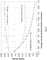
Figure 7 shows a study of the behavior of the proposed cycle focused on the analysis of this parameter. As can be seen, the greater the activity of CaO (more efficient carbonation), the better the yield of the cycle, the lower the cost and size of the storage tanks and heat exchangers.Figure 8 shows the equally yielding regions for the configuration ofFigure 3 , with direct integration, based on the pressure in the carbonator and turbine outlet for specific conditions of the cycle and circulating flows. An optimal operating region is seen based on these parameters with relevant yield values. - The previously published experimental papers on the measurement by means of thermogravimetry of multi-cyclical conversion of CaO derived from limestone have been developed under special conditions for the CO2 capturing process (Perejon A et al. The Calcium-Looping technology for CO2 capture: On the important roles of energy integration and sorbent behavior. Appl Energy 2015; 162:787-807, doi:10.1016/j.apenergy.2015.10.121). These conditions for capturing CO2 consist of calcination at high temperatures and high partial pressure of CO2 and carbonation at low partial pressure of CO2, obtaining a decrease of the capturing yield of CO2 with the number of cycles (
Figure 9 ). After a high number of cycles, the conversion of CaO asymptotically approaches 0.07. - However, the conditions in which the calcination-carbonation cycles are integrated with a power loop in a closed cycle of CO2 comprise carbonation at high partial pressure of CO2, at high temperature. Furthermore, it is desirable that the calcination be carried out at the lowest possible temperature in order to use solar receptors based on metallic alloys available on the market. In such conditions, in the present invention, the multicycle behavior of natural limestone was measured by means of thermogravimetry (B. Sarrion, J. M. Valverde, A. Perejon, L. A. Perez-Maqueda, P. E. Sanchez-Jimenez. On the multicycle activity of natural limestone/dolomite for cheap, efficient and non-toxic Thermochemical Energy Storage of Concentrated Solar Power. Energy Technology. doi. 10.1002/ente.201600068; article in press (not published)). Specifically, the conditions were: carbonation at 850°C in an atmosphere of pure CO2 and calcination at 700°C in an atmosphere of pure He.
Figure 9 shows the results obtained at these conditions based on the number of cycles N. Under these conditions, residual activities greater than 0.5 are obtained, as shown inFigure 9 . In said figure, these results are compared with the results obtained for cycles carried out under conditions for capturing CO2, which were carried out under the following conditions: carbonation at 650°C in an atmosphere of 15% CO2/85% air volume/volume and calcination at 950°C in an atmosphere of 70% CO2/30% air volume/volume. - These results show that the combination of the calcination-carbonation cycle in which CaCO3 is calcined with a power loop in a closed cycle of CO2 has a synergistic effect with the behavior of the natural limestone under these conditions that has not been previously described.
-
-
Figure 1 . - Proposed general configuration (1). Direct integration.
The figure shows the general diagram of the integrated system with direct integration. In the same, the generation turbine is integrated in the power loop itself. The different heat and work exchange elements are indicated as well as accumulation tanks for solids and gases, proposed. -
Figure 2 . -Configuration 2. Direct integration
The figure shows a new configuration on the general diagram of the system with direct integration in which an additional HXG heat exchange train is added. -
Figure 3 . - Configuration 3. Direct integration
The figure shows a new configuration on the diagram ofconfiguration 2, adding a train of parallel exchangers (HXG and HXI) that optimizes the heat recovery process for the stream of CO2 entering the carbonator. -
Figure 4 . - General configuration 4. Indirect integration.
The figure shows the general diagram of the integrated system with indirect integration, so that the heat of the stream of gases (CO2 or mixture) can be used for diverse uses according to demand. The different heat and work exchange elements are indicated as well as accumulation tanks for solids and gases, proposed. -
Figure 5 . -Configuration 5. Indirect integration.
The figure shows a new configuration on the diagram ofconfiguration 5 with indirect integration in which an additional HXG heat exchange train is added. -
Figure 6 . - Configuration 6. Indirect integration.
The figure shows a new configuration with indirect integration on the diagram ofconfiguration 5, adding a train of parallel exchangers (HXG and HXI) that optimizes the heat recovery process for the stream of CO2 entering the carbonator. -
Figure 7 . - Yield according to the activity of the sorbent, configuration and pressure relationship.
The figure shows the yield obtained by using different configurations based on the degree of activity of the sorbent in the carbonation in the optimal point (for each configuration) of the pressure relationship between the carbonator and turbine outlet. -
Figure 8 . - Cycle yield based on the pressure relationship. - Contour plot of the cycle yield based on the ratio of the pressure and of the outlet pressure of the turbine. It is can be seen how better efficiency values are obtained at low outlet pressures in the turbine.
-
Figure 9 . - Conversion of CaO derived from limestone obtained by thermogravimetrical analysis (adapted from B. Sarrion, J. M. Valverde, A. Perejon, L. A. Perez-Maqueda, P. E. Sanchez-Jimenez. On the multicycle activity of natural limestone/dolomite for cheap, efficient and non-toxic Thermochemical Energy Storage of Concentrated Solar Power. Energy Technology, doi. 10.1002/ente.201600068; article in press (not published)). The squares represent the results of calcination-carbonation cycles with optimal operating conditions for the storage of concentrated solar energy according to the present application: carbonation at 850°C in an atmosphere of pure CO2 and calcination at 700°C in an atmosphere of pure He. The figure shows the results obtained at these conditions based on the number of cycles N. The triangles represent the results of calcination-carbonation cycles in conditions for capturing CO2: carbonation at 650°C in an atmosphere of 15% CO2/85% air (volume/volume) and calcination at 950°C in an atmosphere of 70% CO2/30% air (volume/volume).
Claims (10)
- An integrated system for thermochemical energy storage and electric power generation characterized in that a calcination-carbonation cycle in which calcination of CaCO3 is produced is integrated, directly or indirectly, with a power loop in a closed cycle of CO2 or mixture of CO2 with other gases.
- The integrated system according to the preceding claim, characterized in that in the direct integration, the flow of gases of the power loop evolves directly through a main thermal turbine for electric generation.
- The system according to the preceding claim, characterized in that in the indirect integration, the flow of gases of the secondary loop evolves through a series of exchangers in order to provide heat to an external electric generation system or to an industrial process.
- The integrated system, according to the preceding claims, characterized in that there is excess CO2 in the carbonator.
- The integrated system according to the preceding claims, characterized in that in the carbonation phase the heat recovery system comprises series and parallel exchangers and flow bypass.
- The integrated system according to the preceding claims, characterized in that during the calcination, when CO2 and CaO are generated, the heat recovery system between the streams of CaCO3 comprises parallel exchangers and flow divisions.
- The integrated system according to the preceding claims, characterized in that in the energy storage phase, during the calcination phase in which the CaCO3 is decomposed into CO2 and CaO, refrigerated compression is used in several stages.
- The integrated system according to the preceding claims, characterized in that the power loop in a closed cycle of CO2 or mixture of CO2 with other gases is integrated in the carbonator.
- The integrated system according to the preceding claims, characterized in that carbonation is carried out at a pressure of CO2 between 1 and 12 bars.
- The integrated system according to the preceding claims, characterized in that calcination is carried out at a temperature between 675 and 950°C and carbonation is carried out at a temperature between 850 and 950°C.
Applications Claiming Priority (2)
| Application Number | Priority Date | Filing Date | Title |
|---|---|---|---|
| ES201500493A ES2595443B1 (en) | 2015-06-29 | 2015-06-29 | Integrated calcination-carbonation system and closed loop CO2 cycle for thermochemical energy storage and electric power generation |
| PCT/ES2016/070265 WO2017001710A1 (en) | 2015-06-29 | 2016-04-15 | Integrated calcination-carbonation system and closed-loop co2 cycle for thermochemical energy storage and electrical energy generation |
Publications (2)
| Publication Number | Publication Date |
|---|---|
| EP3324018A1 true EP3324018A1 (en) | 2018-05-23 |
| EP3324018A4 EP3324018A4 (en) | 2018-06-06 |
Family
ID=57608153
Family Applications (1)
| Application Number | Title | Priority Date | Filing Date |
|---|---|---|---|
| EP16817295.5A Ceased EP3324018A4 (en) | 2015-06-29 | 2016-04-15 | Integrated calcination-carbonation system and closed-loop co2 cycle for thermochemical energy storage and electrical energy generation |
Country Status (3)
| Country | Link |
|---|---|
| EP (1) | EP3324018A4 (en) |
| ES (1) | ES2595443B1 (en) |
| WO (1) | WO2017001710A1 (en) |
Cited By (14)
| Publication number | Priority date | Publication date | Assignee | Title |
|---|---|---|---|---|
| DE102019107440A1 (en) * | 2019-03-22 | 2020-09-24 | Otto-Von-Guericke-Universität Magdeburg | Solid reactor, system and method for separating carbon dioxide |
| US20230304420A1 (en) * | 2020-11-30 | 2023-09-28 | Rondo Energy, Inc. | Energy storage system and alumina calcination applications |
| US11867093B2 (en) | 2020-11-30 | 2024-01-09 | Rondo Energy, Inc. | Thermal energy storage system with radiation cavities |
| US11913362B2 (en) | 2020-11-30 | 2024-02-27 | Rondo Energy, Inc. | Thermal energy storage system coupled with steam cracking system |
| US12018596B2 (en) | 2020-11-30 | 2024-06-25 | Rondo Energy, Inc. | Thermal energy storage system coupled with thermal power cycle systems |
| US12146424B2 (en) | 2020-11-30 | 2024-11-19 | Rondo Energy, Inc. | Thermal energy storage system coupled with a solid oxide electrolysis system |
| US12291982B2 (en) | 2020-11-30 | 2025-05-06 | Rondo Energy, Inc. | Thermal energy storage systems for use in material processing |
| US12352505B2 (en) | 2023-04-14 | 2025-07-08 | Rondo Energy, Inc. | Thermal energy storage systems with improved seismic stability |
| US12359591B1 (en) | 2020-11-30 | 2025-07-15 | Rondo Energy, Inc. | Thermal energy storage systems for repowering existing power plants for improving efficiency and safety |
| US12480719B2 (en) | 2024-04-24 | 2025-11-25 | Rondo Energy, Inc. | Thermal energy storage system for simple and combined cycle power generation |
| US12566034B1 (en) | 2024-07-02 | 2026-03-03 | Rondo Energy, Inc. | Thermal energy storage system coupled to a heat exchanger with thermal protection |
| US12595973B2 (en) | 2024-05-24 | 2026-04-07 | Rondo Energy, Inc. | Thermal energy storage system with high efficiency heater control |
| US12607170B2 (en) | 2024-07-12 | 2026-04-21 | Rondo Energy, Inc. | Thermal energy storage system for use with a low temperature heat source and a thermal power cycle system |
| US12618343B2 (en) | 2023-10-13 | 2026-05-05 | Rondo Energy, Inc. | Thermal energy storage system with a heat pump for improved efficiency |
Families Citing this family (1)
| Publication number | Priority date | Publication date | Assignee | Title |
|---|---|---|---|---|
| CN113663636B (en) * | 2021-08-31 | 2022-10-14 | 南京工业大学 | Rotary calcium-based high-temperature thermochemical energy storage reaction device and energy storage reaction method |
Family Cites Families (3)
| Publication number | Priority date | Publication date | Assignee | Title |
|---|---|---|---|---|
| EP2385873B1 (en) * | 2008-11-19 | 2018-05-16 | The Ohio State University Research Foundation | Carbonation calcination reaction process for co2 capture using a highly regenerable sorbent |
| ES2555034T3 (en) * | 2013-02-01 | 2015-12-28 | Consejo Superior De Investigaciones Científicas (Csic) | System and procedure for energy storage using circulating fluidized bed combustors |
| DE102013223588A1 (en) * | 2013-11-19 | 2015-05-21 | Hydrogenious Technologies Gmbh | Plant and method for storing energy |
-
2015
- 2015-06-29 ES ES201500493A patent/ES2595443B1/en active Active
-
2016
- 2016-04-15 WO PCT/ES2016/070265 patent/WO2017001710A1/en not_active Ceased
- 2016-04-15 EP EP16817295.5A patent/EP3324018A4/en not_active Ceased
Cited By (45)
| Publication number | Priority date | Publication date | Assignee | Title |
|---|---|---|---|---|
| DE102019107440A1 (en) * | 2019-03-22 | 2020-09-24 | Otto-Von-Guericke-Universität Magdeburg | Solid reactor, system and method for separating carbon dioxide |
| US12291982B2 (en) | 2020-11-30 | 2025-05-06 | Rondo Energy, Inc. | Thermal energy storage systems for use in material processing |
| US11867093B2 (en) | 2020-11-30 | 2024-01-09 | Rondo Energy, Inc. | Thermal energy storage system with radiation cavities |
| US11867096B2 (en) | 2020-11-30 | 2024-01-09 | Rondo Energy, Inc. | Calcination system with thermal energy storage system |
| US11873743B2 (en) | 2020-11-30 | 2024-01-16 | Rondo Energy, Inc. | Methods for material activation with thermal energy storage system |
| US11873742B2 (en) | 2020-11-30 | 2024-01-16 | Rondo Energy, Inc. | Thermal energy storage system with deep discharge |
| US11913361B2 (en) * | 2020-11-30 | 2024-02-27 | Rondo Energy, Inc. | Energy storage system and alumina calcination applications |
| US11913362B2 (en) | 2020-11-30 | 2024-02-27 | Rondo Energy, Inc. | Thermal energy storage system coupled with steam cracking system |
| US11920501B2 (en) | 2020-11-30 | 2024-03-05 | Rondo Energy, Inc. | Thermal energy storage system with steam generation system including flow control and energy cogeneration |
| US20240200470A1 (en) * | 2020-11-30 | 2024-06-20 | Rondo Energy, Inc. | Energy storage system and alumina calcination applications |
| US12018596B2 (en) | 2020-11-30 | 2024-06-25 | Rondo Energy, Inc. | Thermal energy storage system coupled with thermal power cycle systems |
| US12140053B2 (en) | 2020-11-30 | 2024-11-12 | Rondo Energy, Inc. | Thermal energy storage system coupled with steam cracking system |
| US12140054B2 (en) | 2020-11-30 | 2024-11-12 | Rondo Energy, Inc. | Thermal energy storage system coupled with steam cracking system |
| US12146425B2 (en) | 2020-11-30 | 2024-11-19 | Rondo Energy, Inc. | Energy storage system and alumina calcination applications |
| US12146426B2 (en) * | 2020-11-30 | 2024-11-19 | Rondo Energy, Inc. | Energy storage system and alumina calcination applications |
| US12146424B2 (en) | 2020-11-30 | 2024-11-19 | Rondo Energy, Inc. | Thermal energy storage system coupled with a solid oxide electrolysis system |
| US12152509B2 (en) | 2020-11-30 | 2024-11-26 | Rondo Energy, Inc. | Thermal energy storage with fluid flow insulation |
| US12158088B2 (en) | 2020-11-30 | 2024-12-03 | Rondo Energy, Inc. | Thermal energy storage system with radiation cavities |
| US12168943B2 (en) | 2020-11-30 | 2024-12-17 | Rondo Energy, Inc. | Methods for material activation with thermal energy storage system |
| US12188380B2 (en) | 2020-11-30 | 2025-01-07 | Rondo Energy, Inc. | Calcination system with thermal energy storage system |
| US12203394B2 (en) | 2020-11-30 | 2025-01-21 | Rondo Energy, Inc. | Energy storage system and applications |
| US12320277B2 (en) | 2020-11-30 | 2025-06-03 | Rondo Energy, Inc. | Thermal energy storage system with deep discharge |
| US12234751B2 (en) | 2020-11-30 | 2025-02-25 | Rondo Energy, Inc. | Thermal energy storage system coupled with steam cracking system |
| US20230304420A1 (en) * | 2020-11-30 | 2023-09-28 | Rondo Energy, Inc. | Energy storage system and alumina calcination applications |
| US12607136B2 (en) | 2020-11-30 | 2026-04-21 | Rondo Energy, Inc. | Energy storage system and alumina calcination applications |
| US12359591B1 (en) | 2020-11-30 | 2025-07-15 | Rondo Energy, Inc. | Thermal energy storage systems for repowering existing power plants for improving efficiency and safety |
| US12366180B2 (en) | 2020-11-30 | 2025-07-22 | Rondo Energy, Inc. | Thermal energy storage system with steam generation system including flow control and energy cogeneration |
| US12435648B1 (en) | 2020-11-30 | 2025-10-07 | Rondo Energy, Inc. | Thermal energy storage system coupled with thermal power cycle systems |
| US12590549B1 (en) | 2020-11-30 | 2026-03-31 | Rondo Energy, Inc. | Thermal energy storage system coupled with thermal power cycle systems |
| US12486789B2 (en) | 2020-11-30 | 2025-12-02 | Rondo Energy, Inc. | Thermal energy storage systems for use in material processing |
| US12497910B2 (en) | 2020-11-30 | 2025-12-16 | Rondo Energy, Inc. | Thermal energy storage system with radiation cavities |
| US12510006B2 (en) | 2020-11-30 | 2025-12-30 | Rondo Energy, Inc. | Thermal energy storage systems for use in material processing |
| US12516613B1 (en) | 2020-11-30 | 2026-01-06 | Rondo Energy, Inc. | Thermal energy storage system coupled with thermal power cycle systems |
| US12523165B2 (en) | 2020-11-30 | 2026-01-13 | Rondo Energy, Inc. | Thermal energy storage system coupled with steam cracking system |
| US12529327B2 (en) | 2020-11-30 | 2026-01-20 | Rondo Energy, Inc. | Thermal energy storage systems for use in material processing |
| US12529326B2 (en) | 2020-11-30 | 2026-01-20 | Rondo Energy, Inc. | Thermal energy storage with fluid flow insulation |
| US12553366B2 (en) | 2020-11-30 | 2026-02-17 | Rondo Energy, Inc. | Energy storage system and alumina calcination applications |
| US12560105B2 (en) | 2020-11-30 | 2026-02-24 | Rondo Energy, Inc. | Thermal energy storage system with deep discharge |
| US12571331B2 (en) | 2020-11-30 | 2026-03-10 | Rondo Energy, Inc. | Thermal energy storage system with deep discharge |
| US12352505B2 (en) | 2023-04-14 | 2025-07-08 | Rondo Energy, Inc. | Thermal energy storage systems with improved seismic stability |
| US12618343B2 (en) | 2023-10-13 | 2026-05-05 | Rondo Energy, Inc. | Thermal energy storage system with a heat pump for improved efficiency |
| US12480719B2 (en) | 2024-04-24 | 2025-11-25 | Rondo Energy, Inc. | Thermal energy storage system for simple and combined cycle power generation |
| US12595973B2 (en) | 2024-05-24 | 2026-04-07 | Rondo Energy, Inc. | Thermal energy storage system with high efficiency heater control |
| US12566034B1 (en) | 2024-07-02 | 2026-03-03 | Rondo Energy, Inc. | Thermal energy storage system coupled to a heat exchanger with thermal protection |
| US12607170B2 (en) | 2024-07-12 | 2026-04-21 | Rondo Energy, Inc. | Thermal energy storage system for use with a low temperature heat source and a thermal power cycle system |
Also Published As
| Publication number | Publication date |
|---|---|
| WO2017001710A1 (en) | 2017-01-05 |
| ES2595443A1 (en) | 2016-12-30 |
| EP3324018A4 (en) | 2018-06-06 |
| ES2595443B1 (en) | 2017-11-07 |
Similar Documents
| Publication | Publication Date | Title |
|---|---|---|
| ES2595443B1 (en) | Integrated calcination-carbonation system and closed loop CO2 cycle for thermochemical energy storage and electric power generation | |
| Ferrario et al. | Solar-driven calcium looping system for carbon capture in cement plants: process modelling and energy analysis | |
| Alovisio et al. | Optimizing the CSP-calcium looping integration for thermochemical energy storage | |
| CN105737658B (en) | Fluidization calcium base thermochemical high temperature energy storage/release energy system and its working method | |
| US9702348B2 (en) | Chemical looping fluidized-bed concentrating solar power system and method | |
| Ströhle et al. | Feasibility study on the carbonate looping process for post-combustion CO2 capture from coal-fired power plants | |
| Ortiz et al. | A new integration model of the calcium looping technology into coal fired power plants for CO2 capture | |
| CN109441574A (en) | Nearly zero carbon emission integral coal gasification cogeneration technique for peak regulation | |
| Doctor et al. | Oxygen-blown gasification combined cycle: carbon dioxide recovery, transport, and disposal | |
| CN104126058B (en) | Power generation device, power generation method, decomposition gas boiler, and decomposition gas turbine | |
| US20220193607A1 (en) | Solids reactor, system, and method for separating out carbon dioxide, in particular from waste gases | |
| MX2014014945A (en) | Polygeneration production of power and fertilizer through emissions capture. | |
| Wang et al. | Thermodynamic modeling and analysis of a Carnot battery system integrating calcium looping thermochemical energy storage with coal-fired power plant | |
| WO2015048845A1 (en) | A hybrid solar and chemical looping combustion system | |
| Chen et al. | Application of chemical looping air separation for MILD oxy-combustion: identifying a suitable operational region | |
| Chen et al. | Realizing dynamic storage of carbon dioxide and waste heat recovery by integrating methane reforming with CSP-CaL system | |
| CN105485701B (en) | With the coal generating system of calcium-base absorbing agent order decarbonization desulfurization system Deep integrating | |
| Criado et al. | A flexible CO 2 capture system for backup power plants using Ca (OH) 2/CaCO 3 solid storage | |
| Chen et al. | Kinetic investigation and numerical simulation of reactor with prepared diatomite/CaCO3 for high-temperature thermal energy storage application | |
| Wang et al. | Performance analysis of an efficient integration system of coal-fired power plant, solar thermal energy and CO2 capture | |
| Dong et al. | Recovery of waste heat in cement plants for the capture of CO2 | |
| Lobachyov et al. | High efficiency coal-fired power plant of the future | |
| Cannone et al. | An innovative calcium looping process as energy storage system integrated with a solar-powered supercritical CO2 brayton cycle | |
| EP2529825B1 (en) | CO2 capture with carbonate looping | |
| Wang et al. | Thermodynamics analysis of multi-cycle performance of an integrated concentrated solar power, calcium looping and methane reforming system based on exergy approach |
Legal Events
| Date | Code | Title | Description |
|---|---|---|---|
| STAA | Information on the status of an ep patent application or granted ep patent |
Free format text: STATUS: THE INTERNATIONAL PUBLICATION HAS BEEN MADE |
|
| PUAI | Public reference made under article 153(3) epc to a published international application that has entered the european phase |
Free format text: ORIGINAL CODE: 0009012 |
|
| STAA | Information on the status of an ep patent application or granted ep patent |
Free format text: STATUS: REQUEST FOR EXAMINATION WAS MADE |
|
| 17P | Request for examination filed |
Effective date: 20171116 |
|
| AK | Designated contracting states |
Kind code of ref document: A1 Designated state(s): AL AT BE BG CH CY CZ DE DK EE ES FI FR GB GR HR HU IE IS IT LI LT LU LV MC MK MT NL NO PL PT RO RS SE SI SK SM TR |
|
| AX | Request for extension of the european patent |
Extension state: BA ME |
|
| A4 | Supplementary search report drawn up and despatched |
Effective date: 20180508 |
|
| RIC1 | Information provided on ipc code assigned before grant |
Ipc: C01F 11/04 20060101ALI20180502BHEP Ipc: C01F 11/18 20060101ALI20180502BHEP Ipc: F02C 1/00 20060101AFI20180502BHEP |
|
| DAV | Request for validation of the european patent (deleted) | ||
| DAX | Request for extension of the european patent (deleted) | ||
| STAA | Information on the status of an ep patent application or granted ep patent |
Free format text: STATUS: EXAMINATION IS IN PROGRESS |
|
| 17Q | First examination report despatched |
Effective date: 20190426 |
|
| REG | Reference to a national code |
Ref country code: DE Ref legal event code: R003 |
|
| STAA | Information on the status of an ep patent application or granted ep patent |
Free format text: STATUS: THE APPLICATION HAS BEEN REFUSED |
|
| 18R | Application refused |
Effective date: 20211024 |