EP3323994A1 - Airfoil with seal between endwall and airfoil section - Google Patents
Airfoil with seal between endwall and airfoil section Download PDFInfo
- Publication number
- EP3323994A1 EP3323994A1 EP17202407.7A EP17202407A EP3323994A1 EP 3323994 A1 EP3323994 A1 EP 3323994A1 EP 17202407 A EP17202407 A EP 17202407A EP 3323994 A1 EP3323994 A1 EP 3323994A1
- Authority
- EP
- European Patent Office
- Prior art keywords
- section
- airfoil
- seal
- slot
- endwall
- Prior art date
- Legal status (The legal status is an assumption and is not a legal conclusion. Google has not performed a legal analysis and makes no representation as to the accuracy of the status listed.)
- Granted
Links
Images



Classifications
-
- F—MECHANICAL ENGINEERING; LIGHTING; HEATING; WEAPONS; BLASTING
- F01—MACHINES OR ENGINES IN GENERAL; ENGINE PLANTS IN GENERAL; STEAM ENGINES
- F01D—NON-POSITIVE DISPLACEMENT MACHINES OR ENGINES, e.g. STEAM TURBINES
- F01D11/00—Preventing or minimising internal leakage of working-fluid, e.g. between stages
- F01D11/003—Preventing or minimising internal leakage of working-fluid, e.g. between stages by packing rings; Mechanical seals
-
- F—MECHANICAL ENGINEERING; LIGHTING; HEATING; WEAPONS; BLASTING
- F01—MACHINES OR ENGINES IN GENERAL; ENGINE PLANTS IN GENERAL; STEAM ENGINES
- F01D—NON-POSITIVE DISPLACEMENT MACHINES OR ENGINES, e.g. STEAM TURBINES
- F01D5/00—Blades; Blade-carrying members; Heating, heat-insulating, cooling or antivibration means on the blades or the members
- F01D5/12—Blades
- F01D5/14—Form or construction
- F01D5/147—Construction, i.e. structural features, e.g. of weight-saving hollow blades
-
- F—MECHANICAL ENGINEERING; LIGHTING; HEATING; WEAPONS; BLASTING
- F01—MACHINES OR ENGINES IN GENERAL; ENGINE PLANTS IN GENERAL; STEAM ENGINES
- F01D—NON-POSITIVE DISPLACEMENT MACHINES OR ENGINES, e.g. STEAM TURBINES
- F01D5/00—Blades; Blade-carrying members; Heating, heat-insulating, cooling or antivibration means on the blades or the members
- F01D5/12—Blades
- F01D5/14—Form or construction
- F01D5/18—Hollow blades, i.e. blades with cooling or heating channels or cavities; Heating, heat-insulating or cooling means on blades
- F01D5/187—Convection cooling
-
- F—MECHANICAL ENGINEERING; LIGHTING; HEATING; WEAPONS; BLASTING
- F01—MACHINES OR ENGINES IN GENERAL; ENGINE PLANTS IN GENERAL; STEAM ENGINES
- F01D—NON-POSITIVE DISPLACEMENT MACHINES OR ENGINES, e.g. STEAM TURBINES
- F01D5/00—Blades; Blade-carrying members; Heating, heat-insulating, cooling or antivibration means on the blades or the members
- F01D5/12—Blades
- F01D5/28—Selecting particular materials; Particular measures relating thereto; Measures against erosion or corrosion
- F01D5/284—Selection of ceramic materials
-
- F—MECHANICAL ENGINEERING; LIGHTING; HEATING; WEAPONS; BLASTING
- F01—MACHINES OR ENGINES IN GENERAL; ENGINE PLANTS IN GENERAL; STEAM ENGINES
- F01D—NON-POSITIVE DISPLACEMENT MACHINES OR ENGINES, e.g. STEAM TURBINES
- F01D5/00—Blades; Blade-carrying members; Heating, heat-insulating, cooling or antivibration means on the blades or the members
- F01D5/30—Fixing blades to rotors; Blade roots ; Blade spacers
- F01D5/3084—Fixing blades to rotors; Blade roots ; Blade spacers the blades being made of ceramics
-
- F—MECHANICAL ENGINEERING; LIGHTING; HEATING; WEAPONS; BLASTING
- F01—MACHINES OR ENGINES IN GENERAL; ENGINE PLANTS IN GENERAL; STEAM ENGINES
- F01D—NON-POSITIVE DISPLACEMENT MACHINES OR ENGINES, e.g. STEAM TURBINES
- F01D9/00—Stators
- F01D9/02—Nozzles; Nozzle boxes; Stator blades; Guide conduits, e.g. individual nozzles
-
- F—MECHANICAL ENGINEERING; LIGHTING; HEATING; WEAPONS; BLASTING
- F01—MACHINES OR ENGINES IN GENERAL; ENGINE PLANTS IN GENERAL; STEAM ENGINES
- F01D—NON-POSITIVE DISPLACEMENT MACHINES OR ENGINES, e.g. STEAM TURBINES
- F01D9/00—Stators
- F01D9/02—Nozzles; Nozzle boxes; Stator blades; Guide conduits, e.g. individual nozzles
- F01D9/04—Nozzles; Nozzle boxes; Stator blades; Guide conduits, e.g. individual nozzles forming ring or sector
- F01D9/041—Nozzles; Nozzle boxes; Stator blades; Guide conduits, e.g. individual nozzles forming ring or sector using blades
-
- F—MECHANICAL ENGINEERING; LIGHTING; HEATING; WEAPONS; BLASTING
- F02—COMBUSTION ENGINES; HOT-GAS OR COMBUSTION-PRODUCT ENGINE PLANTS
- F02C—GAS-TURBINE PLANTS; AIR INTAKES FOR JET-PROPULSION PLANTS; CONTROLLING FUEL SUPPLY IN AIR-BREATHING JET-PROPULSION PLANTS
- F02C3/00—Gas-turbine plants characterised by the use of combustion products as the working fluid
- F02C3/04—Gas-turbine plants characterised by the use of combustion products as the working fluid having a turbine driving a compressor
-
- F—MECHANICAL ENGINEERING; LIGHTING; HEATING; WEAPONS; BLASTING
- F04—POSITIVE - DISPLACEMENT MACHINES FOR LIQUIDS; PUMPS FOR LIQUIDS OR ELASTIC FLUIDS
- F04D—NON-POSITIVE-DISPLACEMENT PUMPS
- F04D29/00—Details, component parts, or accessories
- F04D29/08—Sealings
- F04D29/083—Sealings especially adapted for elastic fluid pumps
-
- F—MECHANICAL ENGINEERING; LIGHTING; HEATING; WEAPONS; BLASTING
- F04—POSITIVE - DISPLACEMENT MACHINES FOR LIQUIDS; PUMPS FOR LIQUIDS OR ELASTIC FLUIDS
- F04D—NON-POSITIVE-DISPLACEMENT PUMPS
- F04D29/00—Details, component parts, or accessories
- F04D29/26—Rotors specially for elastic fluids
- F04D29/32—Rotors specially for elastic fluids for axial flow pumps
- F04D29/321—Rotors specially for elastic fluids for axial flow pumps for axial flow compressors
- F04D29/324—Blades
-
- F—MECHANICAL ENGINEERING; LIGHTING; HEATING; WEAPONS; BLASTING
- F04—POSITIVE - DISPLACEMENT MACHINES FOR LIQUIDS; PUMPS FOR LIQUIDS OR ELASTIC FLUIDS
- F04D—NON-POSITIVE-DISPLACEMENT PUMPS
- F04D29/00—Details, component parts, or accessories
- F04D29/40—Casings; Connections of working fluid
- F04D29/52—Casings; Connections of working fluid for axial pumps
- F04D29/54—Fluid-guiding means, e.g. diffusers
- F04D29/541—Specially adapted for elastic fluid pumps
- F04D29/542—Bladed diffusers
-
- F—MECHANICAL ENGINEERING; LIGHTING; HEATING; WEAPONS; BLASTING
- F05—INDEXING SCHEMES RELATING TO ENGINES OR PUMPS IN VARIOUS SUBCLASSES OF CLASSES F01-F04
- F05D—INDEXING SCHEME FOR ASPECTS RELATING TO NON-POSITIVE-DISPLACEMENT MACHINES OR ENGINES, GAS-TURBINES OR JET-PROPULSION PLANTS
- F05D2220/00—Application
- F05D2220/30—Application in turbines
- F05D2220/32—Application in turbines in gas turbines
-
- F—MECHANICAL ENGINEERING; LIGHTING; HEATING; WEAPONS; BLASTING
- F05—INDEXING SCHEMES RELATING TO ENGINES OR PUMPS IN VARIOUS SUBCLASSES OF CLASSES F01-F04
- F05D—INDEXING SCHEME FOR ASPECTS RELATING TO NON-POSITIVE-DISPLACEMENT MACHINES OR ENGINES, GAS-TURBINES OR JET-PROPULSION PLANTS
- F05D2230/00—Manufacture
- F05D2230/60—Assembly methods
-
- F—MECHANICAL ENGINEERING; LIGHTING; HEATING; WEAPONS; BLASTING
- F05—INDEXING SCHEMES RELATING TO ENGINES OR PUMPS IN VARIOUS SUBCLASSES OF CLASSES F01-F04
- F05D—INDEXING SCHEME FOR ASPECTS RELATING TO NON-POSITIVE-DISPLACEMENT MACHINES OR ENGINES, GAS-TURBINES OR JET-PROPULSION PLANTS
- F05D2230/00—Manufacture
- F05D2230/90—Coating; Surface treatment
-
- F—MECHANICAL ENGINEERING; LIGHTING; HEATING; WEAPONS; BLASTING
- F05—INDEXING SCHEMES RELATING TO ENGINES OR PUMPS IN VARIOUS SUBCLASSES OF CLASSES F01-F04
- F05D—INDEXING SCHEME FOR ASPECTS RELATING TO NON-POSITIVE-DISPLACEMENT MACHINES OR ENGINES, GAS-TURBINES OR JET-PROPULSION PLANTS
- F05D2240/00—Components
- F05D2240/35—Combustors or associated equipment
-
- F—MECHANICAL ENGINEERING; LIGHTING; HEATING; WEAPONS; BLASTING
- F05—INDEXING SCHEMES RELATING TO ENGINES OR PUMPS IN VARIOUS SUBCLASSES OF CLASSES F01-F04
- F05D—INDEXING SCHEME FOR ASPECTS RELATING TO NON-POSITIVE-DISPLACEMENT MACHINES OR ENGINES, GAS-TURBINES OR JET-PROPULSION PLANTS
- F05D2240/00—Components
- F05D2240/55—Seals
- F05D2240/57—Leaf seals
-
- F—MECHANICAL ENGINEERING; LIGHTING; HEATING; WEAPONS; BLASTING
- F05—INDEXING SCHEMES RELATING TO ENGINES OR PUMPS IN VARIOUS SUBCLASSES OF CLASSES F01-F04
- F05D—INDEXING SCHEME FOR ASPECTS RELATING TO NON-POSITIVE-DISPLACEMENT MACHINES OR ENGINES, GAS-TURBINES OR JET-PROPULSION PLANTS
- F05D2250/00—Geometry
- F05D2250/20—Three-dimensional
-
- F—MECHANICAL ENGINEERING; LIGHTING; HEATING; WEAPONS; BLASTING
- F05—INDEXING SCHEMES RELATING TO ENGINES OR PUMPS IN VARIOUS SUBCLASSES OF CLASSES F01-F04
- F05D—INDEXING SCHEME FOR ASPECTS RELATING TO NON-POSITIVE-DISPLACEMENT MACHINES OR ENGINES, GAS-TURBINES OR JET-PROPULSION PLANTS
- F05D2300/00—Materials; Properties thereof
- F05D2300/10—Metals, alloys or intermetallic compounds
-
- F—MECHANICAL ENGINEERING; LIGHTING; HEATING; WEAPONS; BLASTING
- F05—INDEXING SCHEMES RELATING TO ENGINES OR PUMPS IN VARIOUS SUBCLASSES OF CLASSES F01-F04
- F05D—INDEXING SCHEME FOR ASPECTS RELATING TO NON-POSITIVE-DISPLACEMENT MACHINES OR ENGINES, GAS-TURBINES OR JET-PROPULSION PLANTS
- F05D2300/00—Materials; Properties thereof
- F05D2300/20—Oxide or non-oxide ceramics
-
- Y—GENERAL TAGGING OF NEW TECHNOLOGICAL DEVELOPMENTS; GENERAL TAGGING OF CROSS-SECTIONAL TECHNOLOGIES SPANNING OVER SEVERAL SECTIONS OF THE IPC; TECHNICAL SUBJECTS COVERED BY FORMER USPC CROSS-REFERENCE ART COLLECTIONS [XRACs] AND DIGESTS
- Y02—TECHNOLOGIES OR APPLICATIONS FOR MITIGATION OR ADAPTATION AGAINST CLIMATE CHANGE
- Y02T—CLIMATE CHANGE MITIGATION TECHNOLOGIES RELATED TO TRANSPORTATION
- Y02T50/00—Aeronautics or air transport
- Y02T50/60—Efficient propulsion technologies, e.g. for aircraft
Definitions
- a gas turbine engine typically includes a fan section, a compressor section, a combustor section and a turbine section. Air entering the compressor section is compressed and delivered into the combustion section where it is mixed with fuel and ignited to generate a high-speed exhaust gas flow. The high-speed exhaust gas flow expands through the turbine section to drive the compressor and the fan section.
- the compressor section typically includes low and high pressure compressors, and the turbine section includes low and high pressure turbines.
- the high pressure turbine drives the high pressure compressor through an outer shaft to form a high spool
- the low pressure turbine drives the low pressure compressor through an inner shaft to form a low spool.
- the fan section may also be driven by the low inner shaft.
- a direct drive gas turbine engine includes a fan section driven by the low spool such that the low pressure compressor, low pressure turbine and fan section rotate at a common speed in a common direction.
- a speed reduction device such as an epicyclical gear assembly, may be utilized to drive the fan section such that the fan section may rotate at a speed different than the turbine section.
- a shaft driven by one of the turbine sections provides an input to the epicyclical gear assembly that drives the fan section at a reduced speed.
- An airfoil according to an example of the present disclosure includes an endwall section, and an airfoil section that defines, at least in part, an airfoil profile.
- One of the airfoil section or the endwall section includes a seal cavity.
- a seal is disposed in the seal cavity.
- the endwall section has a first slot.
- the airfoil section includes a second slot, and the first slot and the second slot together form the seal cavity.
- the airfoil section includes a rib, and the second slot is in the rib.
- the airfoil section includes an internal passage, and the rib sub-divides the internal passage.
- the rib is radially elongated.
- the rib has enlarged radial ends.
- the first slot and the second slot are radial slots.
- the seal is a feather seal.
- the airfoil section is formed of ceramic and the seal is formed of metal.
- the airfoil section includes a rib.
- the second slot is in the rib.
- the airfoil section includes an internal passage.
- the rib sub-divides the internal passage.
- the rib is radially elongated, and the seal is a feather seal.
- the seal is rigidly attached with the other one of the airfoil section or the endwall section.
- a gas turbine engine includes a compressor section, a combustor in fluid communication with the compressor section, and a turbine section in fluid communication with the combustor.
- One of the turbine section or the compressor section includes an airfoil that has an endwall section.
- An airfoil section defines, at least in part, an airfoil profile.
- One of the airfoil section or the endwall section includes a seal cavity. A seal is disposed in the seal cavity.
- the endwall section has a first slot.
- the airfoil section includes a second slot, and the first slot and the second slot together form the seal cavity.
- the airfoil section includes a rib
- the second slot is in the rib
- the airfoil section includes an internal passage
- the rib sub-divides the internal passage
- the first slot and the second slot are radial slots.
- the seal is a feather seal.
- the airfoil section is formed of ceramic and the seal is formed of metal.
- the seal is rigidly attached with the other one of the airfoil section or the endwall section.
- a method includes placing a seal into a seal cavity in at least one of an endwall section or an airfoil section by bringing the endwall section and the airfoil section together such that the seal enters into the seal cavity.
- the airfoil section defines, at least in part, an airfoil profile
- the endwall section has a first slot
- the airfoil section includes a second slot
- the first slot and the second slot together form the seal cavity
- the airfoil section includes a rib
- the second slot is in the rib
- the airfoil section includes an internal passage
- the rib sub-divides the internal passage
- the rib is radially elongated
- the seal is a feather seal.
- FIG. 1 schematically illustrates a gas turbine engine 20.
- the gas turbine engine 20 is disclosed herein as a two-spool turbofan that generally incorporates a fan section 22, a compressor section 24, a combustor section 26 and a turbine section 28.
- Alternative engine designs can include an augmentor section (not shown) among other systems or features.
- the fan section 22 drives air along a bypass flow path B in a bypass duct defined within a nacelle 15, while the compressor section 24 drives air along a core flow path C for compression and communication into the combustor section 26 then expansion through the turbine section 28.
- the examples herein are not limited to use with two-spool turbofans and may be applied to other types of turbomachinery, including direct drive engine architectures, three-spool engine architectures, and ground-based turbines.
- the engine 20 generally includes a low speed spool 30 and a high speed spool 32 mounted for rotation about an engine central longitudinal axis A relative to an engine static structure 36 via several bearing systems 38. It should be understood that various bearing systems 38 at various locations may alternatively or additionally be provided, and the location of bearing systems 38 may be varied as appropriate to the application.
- the low speed spool 30 generally includes an inner shaft 40 that interconnects a fan 42, a first (or low) pressure compressor 44 and a first (or low) pressure turbine 46.
- the inner shaft 40 may be connected to the fan 42 through a speed change mechanism, which in exemplary gas turbine engine 20 is illustrated as a geared architecture 48, to drive the fan 42 at a lower speed than the low speed spool 30.
- the high speed spool 32 includes an outer shaft 50 that interconnects a second (or high) pressure compressor 52 and a second (or high) pressure turbine 54.
- a combustor 56 is arranged between the high pressure compressor 52 and the high pressure turbine 54.
- a mid-turbine frame 57 of the engine static structure 36, if included, is arranged generally between the high pressure turbine 54 and the low pressure turbine 46.
- the mid-turbine frame 57 further supports the bearing systems 38 in the turbine section 28.
- the inner shaft 40 and the outer shaft 50 are concentric and rotate via bearing systems 38 about the engine central longitudinal axis A, which is collinear with their longitudinal axes.
- the core airflow is compressed by the low pressure compressor 44 then the high pressure compressor 52, mixed and burned with fuel in the combustor 56, then expanded through the high pressure turbine 54 and low pressure turbine 46.
- the mid-turbine frame 57 includes airfoils 59 which are in the core airflow path C.
- the turbines 46, 54 rotationally drive the respective low speed spool 30 and high speed spool 32 in response to the expansion.
- gear system 48 may be located aft of combustor section 26 or even aft of turbine section 28, and fan section 22 may be positioned forward or aft of the location of gear system 48.
- the engine 20 in one example is a high-bypass geared aircraft engine.
- the engine 20 bypass ratio is greater than about six, with an example embodiment being greater than about ten
- the geared architecture 48 is an epicyclic gear train, such as a planetary gear system or other gear system, with a gear reduction ratio of greater than about 2.3 and the low pressure turbine 46 has a pressure ratio that is greater than about five.
- the engine 20 bypass ratio is greater than about ten
- the fan diameter is significantly larger than that of the low pressure compressor 44
- the low pressure turbine 46 has a pressure ratio that is greater than about five.
- Low pressure turbine 46 pressure ratio is pressure measured prior to inlet of low pressure turbine 46 as related to the pressure at the outlet of the low pressure turbine 46 prior to an exhaust nozzle.
- the geared architecture 48 may be an epicycle gear train, such as a planetary gear system or other gear system, with a gear reduction ratio of greater than about 2.3:1. It should be understood, however, that the above parameters are only exemplary of one embodiment of a geared architecture engine and that the present invention is applicable to other gas turbine engines, including direct drive turbofans and gas turbines with multiple bypass streams.
- the fan section 22 of the engine 20 may be designed for a particular flight condition -- typically cruise at about 0.8 Mach and about 35,000 feet (10,668 m).
- ⁇ TSFC' Thrust Specific Fuel Consumption
- Low fan pressure ratio is the pressure ratio across the fan blade alone, without a Fan Exit Guide Vane (“FEGV”) system.
- the low fan pressure ratio as disclosed herein according to one non-limiting embodiment is less than about 1.45.
- the "Low corrected fan tip speed" as disclosed herein according to one non-limiting embodiment is less than about 1150 ft / second (350.5 m/s).
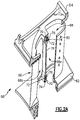
- Figure 2A illustrates a partially cut away view of an example airfoil 60 used in the engine 20, and Figure 2B illustrates an exploded view of the airfoil 60.
- the airfoil 60 can be a turbine vane, as represented at 60a in Figure 1 , or a compressor vane, as represented at 60b in Figure 1 .
- the examples herein may be described in the context of a vane, this disclosure is not limited to vanes, and the examples may also be applicable to blades or other airfoils that are exposed to high temperatures.
- the airfoil 60 includes inner and outer endwall sections 62/64 and an airfoil section 66 that extends radially between the inner and outer endwall sections 62/64.
- the endwall sections 62/64 are platforms that together provide the inner and outer bounds of the core gas path.
- the sections 62/64 may have aerodynamic geometries without platforms; or for a blade, the airfoil 60 may include only an inner end section.
- the airfoil section 66 may be hollow and can include one or more internal passages 68.
- a passage can include a cavity, a channel, or the like.
- the airfoil section 66 defines an airfoil profile, AP, which is the peripheral shape of the airfoil section 66 when viewed in a radial direction.
- the airfoil profile has a wing-like shape that provides a reaction force via Bernoulli's principle with regard to flow over the airfoil section 66.
- the airfoil profile AP generally includes a leading end (LE), a trailing end (TE), a pressure side (PS), and a suction side (SS).
- leading end is the region of the airfoil profile (AP) that includes a leading edge of the airfoil profile (AP)
- trailing end is the region of the airfoil profile that includes a trailing edge.
- the leading edge may be the portion of the airfoil profile (AP) that first contacts air or the foremost edge of the airfoil profile (AP).
- the trailing edge may be the portion of the airfoil profile (AP) that last contacts air or the aftmost edge of the airfoil profile (AP).
- the leading edge may shift, depending on the orientation of the vane.
- the airfoil section 66 is a separate distinct piece from both of the endwall sections 62/64.
- the endwall sections 62/64 trap the airfoil section 66 there between.
- the airfoil section 66 could alternatively be attached to or integral with one of the endwall sections 62/64 and the other of the endwall sections 62/64 may be disposed on the free radial end of the airfoil section 66.
- the endwall sections 62/64 each include respective first slots 70, and the airfoil section 66 includes second slots 72.
- the second slots 72 are disposed at the inner and outer radial ends, respectively, of the airfoil section 66. If the airfoil section 66 were instead attached to or integral with either of the endwall sections 62/64 rather than a separate distinct piece, the airfoil section 66 would have one or more second slots 72 at the free radial end.
- the slots 70/72 may be formed using techniques such as, but not limited to, electro-discharge machining (EDM), casting, laser cutting, or preform formation during lay-up (for ceramic matrix composite material). In the lay-up technique, fiber plies may be arranged around a carbon or other sacrificial piece that has the geometry of the desired slot. Upon thermal processing, the carbon or other sacrificial piece vaporizes, leaving the slot in its place.
- each of the first slots 70 aligns with one of the second slots 72 to form a seal cavity 74.
- a seal 76 is disposed in the seal cavity 74.
- the seal 76 is a feather seal.
- the feather seal is relatively flat and of substantially uniform thickness.
- the feather seal has an aspect ratio of greater than about two.
- the feather seal may have a thickness of approximately 10 mils to 35 mils (254 micrometers to 890 micrometers).
- the geometry of the seal cavity 74 generally replicates the geometry of the feather seal, but the seal cavity 74 may be slightly larger than the feather seal to facilitate assembly.
- the feather seal has an interference fit with the seal cavity 74.
- the sum of the manufacturing tolerance of the seal cavity 74 in the radial direction and the manufacturing tolerance of the feather seal in the radial direction may be no more than approximately 30 mils to 60 mils (762 micrometers to 1524 micrometers).
- the pressure differential urges the feather seal against the lateral sides of the seal cavity 74, in essence conforming the feather seal to the lateral sides.
- the conformance blocks gas from passing by the feather seal and into the airfoil 60.
- the slots 70/72 are radially elongated (with respect to the engine central axis), and the seal 76 is thus radially oriented.
- the slot or slots 72 in the airfoil section 66 are in a rib 78 of the airfoil section 66.
- the rib 78 is elongated and sub-divides the internal passage 68 into sub-passages 68a/68b.
- the rib 78 may have a substantially uniform thickness or the rib 78 may be enlarged at the radial ends to accommodate the presence of the slots 72.
- the seal or seals 76 seal the sub-passages 68a/68b from each other.
- cooling bleed air may be provided to each of the sub-passages 68a/68b; however, the cooling bleed air may be provided from different stages of the compressor section 24 and thus may be at different pressures. Use of higher pressure air from the compressor section 24 (e.g., in the sub-passage 68a) comes at a greater efficiency penalty. Sealing the sub-passages 68a/68b from each other limits or prevents mixing of the cooling bleed air between the sub-passages 68a/68b.
- this reduces loss of the higher pressure cooling bleed air (e.g., from the sub-passage 68a to the sub-passage 68b) and the potential for a "short circuit" of cooling bleed air to intended locations, such as to cooling holes 80 in the sub-passage 68a or elsewhere.
- Figure 2C illustrates a modified example in which the seal 176 is, in essence, integrated into one or the other of the endwall section or the airfoil section.
- like reference numerals designate like elements where appropriate and reference numerals with the addition of one-hundred or multiples thereof designate modified elements that are understood to incorporate the same features and benefits of the corresponding elements.
- the rib 178 includes the seal cavity 174.
- the endwall section 164 (or alternatively, the endwall section 62) includes the seal 176, which is rigidly attached thereto. The seal 176 projects into the seal cavity 174.
- the rigidity of the seal 176 may limit the ability of the seal 176 to conform to the sides of the seal cavity 174.
- the seal 176 may thus function as a shiplap seal.
- the seal 176 could alternatively be on the rib 178 and the seal cavity 174 on the endwall section 164.
- the airfoil section 66 may be formed of a ceramic to enhance thermal resistance.
- the ceramic may include, but is not limited to, oxides, carbides, nitrides, borides, silicides, and combinations thereof.
- a ceramic is a compound of metallic or metalloid elements bonded with nonmetallic elements or metalloid elements primarily in ionic or covalent bonds.
- the ceramic is a monolithic ceramic or a ceramic matrix composite (CMC).
- a monolithic ceramic is composed of a single, homogenous ceramic material.
- a composite is composed of two or more materials that are individually easily distinguishable.
- a CMC has a reinforcement phase, such as ceramic or carbon fibers, dispersed in a ceramic matrix formed of oxides, carbides, nitrides, borides, silicides, or combinations thereof.
- the airfoil section 66 may include or may be formed of a geometric segmented coating section 190, a representative portion of which is shown in Figure 3A .
- the coating section 190 includes a wall 192.
- the wall 192 includes a first or inner side 192a and a second or exterior side 192b that is opposite the first side 192a.
- the second side 192b includes an array of cells 194 defined by cell sidewalls 194a.
- the array is a repeating geometric pattern of one or more cell geometries.
- the cell sidewalls 194a have a uniform thickness.
- the cells 194 are hexagonal.
- the cells 194 may be circular, ovular, other polygonal geometry, or mixed cell geometries.
- the cells may have been machined or cast directly into the wall 192, or machined into a metallic bond coating applied to the wall exterior side 192b. In the case where the cells 194 are machined or cast directly into the substrate of the wall 192, a metallic bond coating may be applied.
- a ceramic based thermal barrier coating 196 is disposed in the array of cells 194.
- the cells 194 mechanically segment the coating 196. This segmentation induces stress relief cracks in the coating 196 making it tolerant to sintering.
- the cells 194 thus provide good spallation resistance of the coating 196, particularly at higher temperature locations. In turn, greater spallation resistance may reduce the need for bleed air for cooling or enable use of higher temperature bleed air that is less of an efficiency penalty.
- the coating 196 may be a barrier coating, such as a thermal barrier or environmental barrier, which is formed of a ceramic.
- the coating 196 may be a monolayer coating but more typically will be a multi-layer coating.
- the coating 196 has a first coating layer 196a and a second coating layer 196b.
- the second coating layer 196b is a topcoat.
- the ceramic material of the coating 196 provides thermal and/or environmental resistance.
- the ceramic material may include or may be yttria stabilized with zirconia, hafnia, and/or gadolinia, gadolinia zirconate, molybdate, alumina, or combinations thereof.
- the coating section 190 may be formed using several different fabrication techniques.
- the wall 192 may be fabricated by investment casting, additive manufacturing, brazing, or combinations thereof, but is not limited to such techniques.
- the cells 194 can be separately fabricated and brazed to the remaining portion of the wall 192, which can be investment cast or additively fabricated.
- the cells 194 can be formed by other techniques, such as depositing an alloy bond coating and removing sections of the alloy coating by machining, electro-discharge machining (EDM), or other removal process.
- EDM electro-discharge machining
- the cells 194 can be machined into the wall 192.
- the coating 196 ceramic coating material is deposited into the cells 194.
- the deposition process can include, but is not limited to, plasma spray or physical vapor deposition.
- plasma spray is used to produce a more durable version of the coating 196.
- the coating 196 has a laminar microstructure.
- the laminar microstructure includes grains of ceramic material that have a high aspect ratio.
- the laminar microstructure is a product of the plasma spray process, in which droplets of melted or partially melted ceramic material are sprayed onto the cells 194. Upon impact, the droplets flatten and solidify, yielding the laminar microstructure.
- the coating 196 has a porosity of less than 10%.
- the ceramic coating material fills or substantially fills the cells 194 and is deposited in a thickness that may be equal to or greater than the height of the cell sidewalls 194a.
- the surface of the coating may have contours from the underlying cells 194. If such contours are undesired, the surface may be machined, ground, or abraded flat. For instance, the surface is reduced down to or close to the tops of the cell sidewalls 194a.
- the seal 76 may be formed of metal.
- Example metals may include, but are not limited to, nickel alloys, cobalt alloys, a nickel alloy coated with cobalt or cobalt alloy, or non-nickel alloys that do not substantially react with ceramic.
- Figure 2B also illustrates a method of assembling the airfoil 60.
- the method includes placing the seal 76 into either the first slot 70 in one of the endwall sections 62/64 or the second slot 72 in the airfoil section 66.
- the endwall section 62 and/or 64 and the airfoil section 66 are then brought together such that the first slot 70 and the second slot 72 form the seal cavity 74 with the seal 76 in the seal cavity 74.
- the seal 176 is placed into the seal cavity 174 by bringing the endwall section 164 and the airfoil section (i.e., the rib 178) together such that the seal 176 is enters into the seal cavity 174.
- the method may be performed in connection with the assembly of a new airfoil or in connection with re-assembling an existing airfoil that was disassembled for repair, refurbishment, etc.
Landscapes
- Engineering & Computer Science (AREA)
- Mechanical Engineering (AREA)
- General Engineering & Computer Science (AREA)
- Chemical & Material Sciences (AREA)
- Ceramic Engineering (AREA)
- Architecture (AREA)
- Materials Engineering (AREA)
- Combustion & Propulsion (AREA)
- Structures Of Non-Positive Displacement Pumps (AREA)
Abstract
Description
- A gas turbine engine typically includes a fan section, a compressor section, a combustor section and a turbine section. Air entering the compressor section is compressed and delivered into the combustion section where it is mixed with fuel and ignited to generate a high-speed exhaust gas flow. The high-speed exhaust gas flow expands through the turbine section to drive the compressor and the fan section. The compressor section typically includes low and high pressure compressors, and the turbine section includes low and high pressure turbines.
- The high pressure turbine drives the high pressure compressor through an outer shaft to form a high spool, and the low pressure turbine drives the low pressure compressor through an inner shaft to form a low spool. The fan section may also be driven by the low inner shaft. A direct drive gas turbine engine includes a fan section driven by the low spool such that the low pressure compressor, low pressure turbine and fan section rotate at a common speed in a common direction.
- A speed reduction device, such as an epicyclical gear assembly, may be utilized to drive the fan section such that the fan section may rotate at a speed different than the turbine section. In such engine architectures, a shaft driven by one of the turbine sections provides an input to the epicyclical gear assembly that drives the fan section at a reduced speed.
- An airfoil according to an example of the present disclosure includes an endwall section, and an airfoil section that defines, at least in part, an airfoil profile. One of the airfoil section or the endwall section includes a seal cavity. A seal is disposed in the seal cavity.
- In an embodiment of the foregoing, the endwall section has a first slot. The airfoil section includes a second slot, and the first slot and the second slot together form the seal cavity.
- In a further embodiment of any of the foregoing embodiments, the airfoil section includes a rib, and the second slot is in the rib.
- In a further embodiment of any of the foregoing embodiments, the airfoil section includes an internal passage, and the rib sub-divides the internal passage.
- In a further embodiment of any of the foregoing embodiments, the rib is radially elongated.
- In a further embodiment of any of the foregoing embodiments, the rib has enlarged radial ends.
- In a further embodiment of any of the foregoing embodiments, the first slot and the second slot are radial slots.
- In a further embodiment of any of the foregoing embodiments, the seal is a feather seal.
- In a further embodiment of any of the foregoing embodiments, the airfoil section is formed of ceramic and the seal is formed of metal.
- In a further embodiment of any of the foregoing embodiments, the airfoil section includes a rib. The second slot is in the rib. The airfoil section includes an internal passage. The rib sub-divides the internal passage. The rib is radially elongated, and the seal is a feather seal.
- In a further embodiment of any of the foregoing embodiments, the seal is rigidly attached with the other one of the airfoil section or the endwall section.
- A gas turbine engine according to an example of the present disclosure includes a compressor section, a combustor in fluid communication with the compressor section, and a turbine section in fluid communication with the combustor. One of the turbine section or the compressor section includes an airfoil that has an endwall section. An airfoil section defines, at least in part, an airfoil profile. One of the airfoil section or the endwall section includes a seal cavity. A seal is disposed in the seal cavity.
- In an embodiment of the foregoing, the endwall section has a first slot. The airfoil section includes a second slot, and the first slot and the second slot together form the seal cavity.
- In a further embodiment of any of the foregoing embodiments, the airfoil section includes a rib, the second slot is in the rib, the airfoil section includes an internal passage, and the rib sub-divides the internal passage.
- In a further embodiment of any of the foregoing embodiments, the first slot and the second slot are radial slots.
- In a further embodiment of any of the foregoing embodiments, the seal is a feather seal.
- In a further embodiment of any of the foregoing embodiments, the airfoil section is formed of ceramic and the seal is formed of metal.
- In a further embodiment of any of the foregoing embodiments, the seal is rigidly attached with the other one of the airfoil section or the endwall section.
- A method according to an example of the present disclosure includes placing a seal into a seal cavity in at least one of an endwall section or an airfoil section by bringing the endwall section and the airfoil section together such that the seal enters into the seal cavity. The airfoil section defines, at least in part, an airfoil profile,
- In an embodiment of the foregoing, the endwall section has a first slot, the airfoil section includes a second slot, the first slot and the second slot together form the seal cavity, the airfoil section includes a rib, the second slot is in the rib, the airfoil section includes an internal passage, the rib sub-divides the internal passage, the rib is radially elongated, and the seal is a feather seal.
- The various features and advantages of the present disclosure will become apparent to those skilled in the art from the following detailed description. The drawings that accompany the detailed description can be briefly described as follows.
-
Figure 1 illustrates an example gas turbine engine. -
Figure 2A illustrates a partially cut away view of an airfoil. -
Figure 2B illustrates an exploded view of the airfoil ofFigure 2A . -
Figure 2C illustrates another example with a seal cavity and an integrated seal. -
Figure 3A illustrates a sectioned view of a geometrically segmented coating section. -
Figure 3B illustrates a wall of the geometrically segmented coating section ofFigure 3A , without the coating. -
Figure 1 schematically illustrates agas turbine engine 20. Thegas turbine engine 20 is disclosed herein as a two-spool turbofan that generally incorporates afan section 22, acompressor section 24, acombustor section 26 and aturbine section 28. Alternative engine designs can include an augmentor section (not shown) among other systems or features. - The
fan section 22 drives air along a bypass flow path B in a bypass duct defined within anacelle 15, while thecompressor section 24 drives air along a core flow path C for compression and communication into thecombustor section 26 then expansion through theturbine section 28. Although depicted as a two-spool turbofan gas turbine engine in the disclosed non-limiting embodiment, the examples herein are not limited to use with two-spool turbofans and may be applied to other types of turbomachinery, including direct drive engine architectures, three-spool engine architectures, and ground-based turbines. - The
engine 20 generally includes alow speed spool 30 and a high speed spool 32 mounted for rotation about an engine central longitudinal axis A relative to an enginestatic structure 36 viaseveral bearing systems 38. It should be understood thatvarious bearing systems 38 at various locations may alternatively or additionally be provided, and the location ofbearing systems 38 may be varied as appropriate to the application. - The
low speed spool 30 generally includes aninner shaft 40 that interconnects afan 42, a first (or low)pressure compressor 44 and a first (or low)pressure turbine 46. Theinner shaft 40 may be connected to thefan 42 through a speed change mechanism, which in exemplarygas turbine engine 20 is illustrated as a gearedarchitecture 48, to drive thefan 42 at a lower speed than thelow speed spool 30. - The high speed spool 32 includes an
outer shaft 50 that interconnects a second (or high)pressure compressor 52 and a second (or high)pressure turbine 54. Acombustor 56 is arranged between thehigh pressure compressor 52 and thehigh pressure turbine 54. Amid-turbine frame 57 of the enginestatic structure 36, if included, is arranged generally between thehigh pressure turbine 54 and thelow pressure turbine 46. Themid-turbine frame 57 further supports the bearingsystems 38 in theturbine section 28. Theinner shaft 40 and theouter shaft 50 are concentric and rotate via bearingsystems 38 about the engine central longitudinal axis A, which is collinear with their longitudinal axes. - The core airflow is compressed by the
low pressure compressor 44 then thehigh pressure compressor 52, mixed and burned with fuel in thecombustor 56, then expanded through thehigh pressure turbine 54 andlow pressure turbine 46. Themid-turbine frame 57 includesairfoils 59 which are in the core airflow path C. Theturbines low speed spool 30 and high speed spool 32 in response to the expansion. It will be appreciated that each of the positions of thefan section 22,compressor section 24,combustor section 26,turbine section 28, and fandrive gear system 48 may be varied. For example,gear system 48 may be located aft ofcombustor section 26 or even aft ofturbine section 28, andfan section 22 may be positioned forward or aft of the location ofgear system 48. - The
engine 20 in one example is a high-bypass geared aircraft engine. In a further example, theengine 20 bypass ratio is greater than about six, with an example embodiment being greater than about ten, the gearedarchitecture 48 is an epicyclic gear train, such as a planetary gear system or other gear system, with a gear reduction ratio of greater than about 2.3 and thelow pressure turbine 46 has a pressure ratio that is greater than about five. In one disclosed embodiment, theengine 20 bypass ratio is greater than about ten, the fan diameter is significantly larger than that of thelow pressure compressor 44, and thelow pressure turbine 46 has a pressure ratio that is greater than about five.Low pressure turbine 46 pressure ratio is pressure measured prior to inlet oflow pressure turbine 46 as related to the pressure at the outlet of thelow pressure turbine 46 prior to an exhaust nozzle. The gearedarchitecture 48 may be an epicycle gear train, such as a planetary gear system or other gear system, with a gear reduction ratio of greater than about 2.3:1. It should be understood, however, that the above parameters are only exemplary of one embodiment of a geared architecture engine and that the present invention is applicable to other gas turbine engines, including direct drive turbofans and gas turbines with multiple bypass streams. - A significant amount of thrust is provided by the bypass flow B due to the high bypass ratio. The
fan section 22 of theengine 20 may be designed for a particular flight condition -- typically cruise at about 0.8 Mach and about 35,000 feet (10,668 m). The flight condition of 0.8 Mach and 35,000 ft (10,668 m), with the engine at its best fuel consumption - also known as "bucket cruise Thrust Specific Fuel Consumption (`TSFC')" - is the industry standard parameter of lbm of fuel being burned divided by lbf of thrust the engine produces at that minimum point. "Low fan pressure ratio" is the pressure ratio across the fan blade alone, without a Fan Exit Guide Vane ("FEGV") system. The low fan pressure ratio as disclosed herein according to one non-limiting embodiment is less than about 1.45. "Low corrected fan tip speed" is the actual fan tip speed in ft/sec divided by an industry standard temperature correction of [(Tram °R) / (518.7 °R)]0.5 (where °R = K x 9/5). The "Low corrected fan tip speed" as disclosed herein according to one non-limiting embodiment is less than about 1150 ft / second (350.5 m/s). - In gas turbine engines air is often bled from the compressor for cooling components in the turbine that cannot withstand stoichiometric ideal temperatures of fuel burn; however, compressor bleed penalizes engine efficiency. Efficiency is governed by thermodynamics and mass flow through the turbine. Efficiency can generally be increased by lowering volume of compressor bleed, increasing velocity of compressor bleed, or increasing temperature of compressor bleed. These goals are challenging to meet because compressor bleed relies on the pressure differential between the compressor and the turbine. That is, the goals of lower volume, increased velocity, and increased temperature of compressor bleed are generally opposite to the goals of high pressure and low temperature compressor bleed desired for achieving good pressure differential. In this regard, to facilitate overcoming such challenges, an approach taken in this disclosure is to reduce the need for compressor bleed and cooling by enhancing the temperature resistance capability of the turbine or other components exposed to high temperatures. In particular, thermal resistance can be enhanced at the compressor exit and turbine inlet.
-
Figure 2A illustrates a partially cut away view of anexample airfoil 60 used in theengine 20, andFigure 2B illustrates an exploded view of theairfoil 60. For instance, theairfoil 60 can be a turbine vane, as represented at 60a inFigure 1 , or a compressor vane, as represented at 60b inFigure 1 . As will be appreciated, although the examples herein may be described in the context of a vane, this disclosure is not limited to vanes, and the examples may also be applicable to blades or other airfoils that are exposed to high temperatures. - The
airfoil 60 includes inner andouter endwall sections 62/64 and anairfoil section 66 that extends radially between the inner andouter endwall sections 62/64. In this example, theendwall sections 62/64 are platforms that together provide the inner and outer bounds of the core gas path. Alternatively, for a variable vane, thesections 62/64 may have aerodynamic geometries without platforms; or for a blade, theairfoil 60 may include only an inner end section. Theairfoil section 66 may be hollow and can include one or moreinternal passages 68. A passage can include a cavity, a channel, or the like. - The
airfoil section 66 defines an airfoil profile, AP, which is the peripheral shape of theairfoil section 66 when viewed in a radial direction. For example, the airfoil profile has a wing-like shape that provides a reaction force via Bernoulli's principle with regard to flow over theairfoil section 66. The airfoil profile AP generally includes a leading end (LE), a trailing end (TE), a pressure side (PS), and a suction side (SS). For example, the leading end (LE) is the region of the airfoil profile (AP) that includes a leading edge of the airfoil profile (AP), and the trailing end (TE) is the region of the airfoil profile that includes a trailing edge. The leading edge may be the portion of the airfoil profile (AP) that first contacts air or the foremost edge of the airfoil profile (AP). The trailing edge may be the portion of the airfoil profile (AP) that last contacts air or the aftmost edge of the airfoil profile (AP). For a variable vane, the leading edge may shift, depending on the orientation of the vane. - In the illustrated example, the
airfoil section 66 is a separate distinct piece from both of theendwall sections 62/64. For example, theendwall sections 62/64 trap theairfoil section 66 there between. However, it is to be understood that theairfoil section 66 could alternatively be attached to or integral with one of theendwall sections 62/64 and the other of theendwall sections 62/64 may be disposed on the free radial end of theairfoil section 66. - In the illustrated example, the
endwall sections 62/64 each include respectivefirst slots 70, and theairfoil section 66 includessecond slots 72. In this example, thesecond slots 72 are disposed at the inner and outer radial ends, respectively, of theairfoil section 66. If theairfoil section 66 were instead attached to or integral with either of theendwall sections 62/64 rather than a separate distinct piece, theairfoil section 66 would have one or moresecond slots 72 at the free radial end. Theslots 70/72 may be formed using techniques such as, but not limited to, electro-discharge machining (EDM), casting, laser cutting, or preform formation during lay-up (for ceramic matrix composite material). In the lay-up technique, fiber plies may be arranged around a carbon or other sacrificial piece that has the geometry of the desired slot. Upon thermal processing, the carbon or other sacrificial piece vaporizes, leaving the slot in its place. - When the
airfoil section 66 is brought together with theendwall sections 62/64, each of thefirst slots 70 aligns with one of thesecond slots 72 to form aseal cavity 74. Aseal 76 is disposed in theseal cavity 74. Thus, for every pair of first andsecond slots 70/72 there is oneseal cavity 74 and oneseal 76 in the oneseal cavity 74. - In the example shown, the
seal 76 is a feather seal. The feather seal is relatively flat and of substantially uniform thickness. For example, the feather seal has an aspect ratio of greater than about two. In further examples, the feather seal may have a thickness of approximately 10 mils to 35 mils (254 micrometers to 890 micrometers). The geometry of theseal cavity 74 generally replicates the geometry of the feather seal, but theseal cavity 74 may be slightly larger than the feather seal to facilitate assembly. In one example, the feather seal has an interference fit with theseal cavity 74. In further examples, the sum of the manufacturing tolerance of theseal cavity 74 in the radial direction and the manufacturing tolerance of the feather seal in the radial direction may be no more than approximately 30 mils to 60 mils (762 micrometers to 1524 micrometers). There may be a pressure differential across the feather seal. The pressure differential urges the feather seal against the lateral sides of theseal cavity 74, in essence conforming the feather seal to the lateral sides. The conformance, in turn, blocks gas from passing by the feather seal and into theairfoil 60. - In the illustrated example, the
slots 70/72 are radially elongated (with respect to the engine central axis), and theseal 76 is thus radially oriented. The slot orslots 72 in theairfoil section 66 are in arib 78 of theairfoil section 66. For instance, therib 78 is elongated and sub-divides theinternal passage 68 intosub-passages 68a/68b. Therib 78 may have a substantially uniform thickness or therib 78 may be enlarged at the radial ends to accommodate the presence of theslots 72. The seal or seals 76 seal the sub-passages 68a/68b from each other. For example, cooling bleed air may be provided to each of the sub-passages 68a/68b; however, the cooling bleed air may be provided from different stages of thecompressor section 24 and thus may be at different pressures. Use of higher pressure air from the compressor section 24 (e.g., in the sub-passage 68a) comes at a greater efficiency penalty. Sealing the sub-passages 68a/68b from each other limits or prevents mixing of the cooling bleed air between the sub-passages 68a/68b. In turn, this reduces loss of the higher pressure cooling bleed air (e.g., from the sub-passage 68a to the sub-passage 68b) and the potential for a "short circuit" of cooling bleed air to intended locations, such as tocooling holes 80 in the sub-passage 68a or elsewhere. -
Figure 2C illustrates a modified example in which theseal 176 is, in essence, integrated into one or the other of the endwall section or the airfoil section. In this disclosure, like reference numerals designate like elements where appropriate and reference numerals with the addition of one-hundred or multiples thereof designate modified elements that are understood to incorporate the same features and benefits of the corresponding elements. In this example, therib 178 includes theseal cavity 174. Rather, than a slot, the endwall section 164 (or alternatively, the endwall section 62) includes theseal 176, which is rigidly attached thereto. Theseal 176 projects into theseal cavity 174. Unlike the feather seal though, the rigidity of theseal 176 may limit the ability of theseal 176 to conform to the sides of theseal cavity 174. Theseal 176 may thus function as a shiplap seal. As will be appreciated, theseal 176 could alternatively be on therib 178 and theseal cavity 174 on theendwall section 164. - The
airfoil section 66 may be formed of a ceramic to enhance thermal resistance. The ceramic may include, but is not limited to, oxides, carbides, nitrides, borides, silicides, and combinations thereof. A ceramic is a compound of metallic or metalloid elements bonded with nonmetallic elements or metalloid elements primarily in ionic or covalent bonds. In further examples, the ceramic is a monolithic ceramic or a ceramic matrix composite (CMC). For example, a monolithic ceramic is composed of a single, homogenous ceramic material. In comparison, a composite is composed of two or more materials that are individually easily distinguishable. A CMC has a reinforcement phase, such as ceramic or carbon fibers, dispersed in a ceramic matrix formed of oxides, carbides, nitrides, borides, silicides, or combinations thereof. - In another example, the
airfoil section 66 may include or may be formed of a geometricsegmented coating section 190, a representative portion of which is shown inFigure 3A . Thecoating section 190 includes awall 192. Thewall 192 includes a first orinner side 192a and a second orexterior side 192b that is opposite thefirst side 192a. Thesecond side 192b includes an array ofcells 194 defined bycell sidewalls 194a. The array is a repeating geometric pattern of one or more cell geometries. In this example, thecell sidewalls 194a have a uniform thickness. As shown in the isolated view of thewall 192 inFigure 3B , thecells 194 are hexagonal. Alternatively, thecells 194 may be circular, ovular, other polygonal geometry, or mixed cell geometries. The cells may have been machined or cast directly into thewall 192, or machined into a metallic bond coating applied to thewall exterior side 192b. In the case where thecells 194 are machined or cast directly into the substrate of thewall 192, a metallic bond coating may be applied. - A ceramic based
thermal barrier coating 196 is disposed in the array ofcells 194. Thecells 194 mechanically segment thecoating 196. This segmentation induces stress relief cracks in thecoating 196 making it tolerant to sintering. Thecells 194 thus provide good spallation resistance of thecoating 196, particularly at higher temperature locations. In turn, greater spallation resistance may reduce the need for bleed air for cooling or enable use of higher temperature bleed air that is less of an efficiency penalty. - The
coating 196 may be a barrier coating, such as a thermal barrier or environmental barrier, which is formed of a ceramic. Thecoating 196 may be a monolayer coating but more typically will be a multi-layer coating. For instance, thecoating 196 has afirst coating layer 196a and asecond coating layer 196b. In this example, thesecond coating layer 196b is a topcoat. - The ceramic material of the
coating 196 provides thermal and/or environmental resistance. As an example, the ceramic material may include or may be yttria stabilized with zirconia, hafnia, and/or gadolinia, gadolinia zirconate, molybdate, alumina, or combinations thereof. - The
coating section 190 may be formed using several different fabrication techniques. As an example, thewall 192 may be fabricated by investment casting, additive manufacturing, brazing, or combinations thereof, but is not limited to such techniques. For instance, thecells 194 can be separately fabricated and brazed to the remaining portion of thewall 192, which can be investment cast or additively fabricated. Alternatively, thecells 194 can be formed by other techniques, such as depositing an alloy bond coating and removing sections of the alloy coating by machining, electro-discharge machining (EDM), or other removal process. In another scenario thecells 194 can be machined into thewall 192. - To produce the
coating 196, ceramic coating material is deposited into thecells 194. The deposition process can include, but is not limited to, plasma spray or physical vapor deposition. In one example, plasma spray is used to produce a more durable version of thecoating 196. For instance, thecoating 196 has a laminar microstructure. The laminar microstructure includes grains of ceramic material that have a high aspect ratio. The laminar microstructure is a product of the plasma spray process, in which droplets of melted or partially melted ceramic material are sprayed onto thecells 194. Upon impact, the droplets flatten and solidify, yielding the laminar microstructure. There may be voids or pores among the grains; however, thecoating 196 is substantially fully dense. For instance, thecoating 196 has a porosity of less than 10%. - The ceramic coating material fills or substantially fills the
cells 194 and is deposited in a thickness that may be equal to or greater than the height of thecell sidewalls 194a. At this stage, the surface of the coating may have contours from theunderlying cells 194. If such contours are undesired, the surface may be machined, ground, or abraded flat. For instance, the surface is reduced down to or close to the tops of thecell sidewalls 194a. - The
seal 76 may be formed of metal. Example metals may include, but are not limited to, nickel alloys, cobalt alloys, a nickel alloy coated with cobalt or cobalt alloy, or non-nickel alloys that do not substantially react with ceramic. -
Figure 2B also illustrates a method of assembling theairfoil 60. For example, the method includes placing theseal 76 into either thefirst slot 70 in one of theendwall sections 62/64 or thesecond slot 72 in theairfoil section 66. Theendwall section 62 and/or 64 and theairfoil section 66 are then brought together such that thefirst slot 70 and thesecond slot 72 form theseal cavity 74 with theseal 76 in theseal cavity 74. For theseal 176, theseal 176 is placed into theseal cavity 174 by bringing theendwall section 164 and the airfoil section (i.e., the rib 178) together such that theseal 176 is enters into theseal cavity 174. The method may be performed in connection with the assembly of a new airfoil or in connection with re-assembling an existing airfoil that was disassembled for repair, refurbishment, etc. - Although a combination of features is shown in the illustrated examples, not all of them need to be combined to realize the benefits of various embodiments of this disclosure. In other words, a system designed according to an embodiment of this disclosure will not necessarily include all of the features shown in any one of the Figures or all of the portions schematically shown in the Figures. Moreover, selected features of one example embodiment may be combined with selected features of other example embodiments.
- The preceding description is exemplary rather than limiting in nature. Variations and modifications to the disclosed examples may become apparent to those skilled in the art that do not necessarily depart from this disclosure. The scope of legal protection given to this disclosure can only be determined by studying the following claims.
Claims (15)
- An airfoil (60) comprising:an endwall section (62,64;164);an airfoil section (66) defining, at least in part, an airfoil profile (AP), at least one of the airfoil section (66) or the endwall section (62,64;164) including a seal cavity (74; 174); anda seal (76; 176) disposed in the seal cavity (74; 174).
- The airfoil (60) as recited in claim 1, wherein the endwall section (62,64;164) has a first slot (70), the airfoil section (66) includes a second slot (72), and the first slot (70) and the second slot (72) together form the seal cavity (74; 174).
- The airfoil (60) as recited in claim 2, wherein the airfoil section (66) includes a rib (78; 178), and the second slot (72) is in the rib (78; 178).
- The airfoil (60) as recited in claim 3, wherein the airfoil section (66) includes an internal passage (68), and the rib (78; 178) subdivides the internal passage (68).
- The airfoil (60) as recited in claim 3 or 4, wherein the rib (78;178) is radially elongated.
- The airfoil (60) as recited in claim 3, 4 or 5, wherein the rib (78;178) has enlarged radial ends.
- The airfoil (60) as recited in any of claims 2 to 6, wherein the first slot (70) and the second slot (72) are radial slots.
- The airfoil (60) as recited in any preceding claim, wherein the seal (76;176) is a feather seal.
- The airfoil (60) as recited in any preceding claim, wherein the airfoil section (66) is formed of ceramic and the seal (76; 176) is formed of metal.
- The airfoil (60) as recited in any preceding claim, wherein the seal (76;176) is rigidly attached with the other one of the airfoil section (66) or the endwall section (62,64;164).
- A gas turbine engine (20) comprising:a compressor section (24);a combustor (56) in fluid communication with the compressor section (24); anda turbine section (28) in fluid communication with the combustor (56), at least one of the turbine section (28) or the compressor section (24) including the airfoil (60) of any preceding claim.
- A method comprising placing a seal (76;176) into a seal cavity (74;174) in at least one of an endwall section (62,64;164) or an airfoil section (66), wherein the airfoil section (66) defines, at least in part, an airfoil profile (AP), by bringing the endwall section (62,64;164) and the airfoil section (66) together such that the seal (76;176) enters the seal cavity (74; 174).
- The method as recited in claim 12, wherein the endwall section (62,64;164) has a first slot (70), the airfoil section (66) includes a second slot (72), and the first slot (70) and the second slot (72) together form the seal cavity (74; 174).
- The method as recited in claim 13, wherein the airfoil section (66) includes a rib (78;178), the second slot (72) is in the rib (78;178), the airfoil section (66) includes an internal passage (68), the rib (78;178) sub-divides the internal passage (68), and the rib (78; 178) is radially elongated.
- The method as recited in claim 12, 13 or 14, wherein the seal (76;176) is a feather seal.
Applications Claiming Priority (1)
| Application Number | Priority Date | Filing Date | Title |
|---|---|---|---|
| US15/354,070 US10458262B2 (en) | 2016-11-17 | 2016-11-17 | Airfoil with seal between endwall and airfoil section |
Publications (2)
| Publication Number | Publication Date |
|---|---|
| EP3323994A1 true EP3323994A1 (en) | 2018-05-23 |
| EP3323994B1 EP3323994B1 (en) | 2021-10-13 |
Family
ID=60387947
Family Applications (1)
| Application Number | Title | Priority Date | Filing Date |
|---|---|---|---|
| EP17202407.7A Active EP3323994B1 (en) | 2016-11-17 | 2017-11-17 | Airfoil with seal between endwall and airfoil section |
Country Status (2)
| Country | Link |
|---|---|
| US (2) | US10458262B2 (en) |
| EP (1) | EP3323994B1 (en) |
Families Citing this family (4)
| Publication number | Priority date | Publication date | Assignee | Title |
|---|---|---|---|---|
| US10934868B2 (en) * | 2018-09-12 | 2021-03-02 | Rolls-Royce North American Technologies Inc. | Turbine vane assembly with variable position support |
| US11156106B2 (en) * | 2019-02-11 | 2021-10-26 | General Electric Company | Controlling extent of TBC sheet spall |
| US11156116B2 (en) | 2019-04-08 | 2021-10-26 | Honeywell International Inc. | Turbine nozzle with reduced leakage feather seals |
| US11473444B2 (en) * | 2019-11-08 | 2022-10-18 | Raytheon Technologies Corporation | Ceramic airfoil with cooling air turn |
Citations (14)
| Publication number | Priority date | Publication date | Assignee | Title |
|---|---|---|---|---|
| US4786234A (en) * | 1982-06-21 | 1988-11-22 | Teledyne Industries, Inc. | Turbine airfoil |
| US4856962A (en) * | 1988-02-24 | 1989-08-15 | United Technologies Corporation | Variable inlet guide vane |
| EP1239119A1 (en) * | 2001-03-07 | 2002-09-11 | General Electric Company | Turbine vane assembly including a low ductility vane |
| GB2378733A (en) * | 2001-08-16 | 2003-02-19 | Rolls Royce Plc | Blade tips for turbines |
| US20060228211A1 (en) * | 2005-04-07 | 2006-10-12 | Siemens Westinghouse Power Corporation | Multi-piece turbine vane assembly |
| JP2007255224A (en) * | 2006-03-20 | 2007-10-04 | Mitsubishi Heavy Ind Ltd | Turbine blade and gas turbine |
| US20100068034A1 (en) * | 2008-09-18 | 2010-03-18 | Schiavo Anthony L | CMC Vane Assembly Apparatus and Method |
| EP2636846A1 (en) * | 2012-03-06 | 2013-09-11 | General Electric Company | Fabricated turbine airfoil |
| US20130343878A1 (en) * | 2012-06-22 | 2013-12-26 | United Technologies Corporation | Turbine engine variable area vane with feather seal |
| WO2013189883A1 (en) * | 2012-06-18 | 2013-12-27 | Alstom Technology Ltd | Seal between static turbine parts |
| WO2015075233A2 (en) * | 2013-11-25 | 2015-05-28 | Alstom Technology Ltd | Guide vane assembly on the basis of a modular structure |
| US20160102577A1 (en) * | 2014-10-13 | 2016-04-14 | Pw Power Systems, Inc. | Power turbine cooling air metering ring |
| EP3091187A1 (en) * | 2015-05-05 | 2016-11-09 | General Electric Company | Turbine component assembly with thermally stress-free fastener |
| EP3159484A1 (en) * | 2015-10-20 | 2017-04-26 | General Electric Company | Gas turbine engine arcuate leaf seal assembly and corresponding segmented turbine nozzle |
Family Cites Families (49)
| Publication number | Priority date | Publication date | Assignee | Title |
|---|---|---|---|---|
| US3215511A (en) | 1962-03-30 | 1965-11-02 | Union Carbide Corp | Gas turbine nozzle vane and like articles |
| US4137008A (en) | 1977-09-21 | 1979-01-30 | The United States Of America As Represented By The Secretary Of The Navy | Adjustable blowing slot for circulation control airfoil |
| US4247259A (en) | 1979-04-18 | 1981-01-27 | Avco Corporation | Composite ceramic/metallic turbine blade and method of making same |
| DE3110098C2 (en) | 1981-03-16 | 1983-03-17 | MTU Motoren- und Turbinen-Union München GmbH, 8000 München | Turbine guide vane for gas turbine engines |
| JPS6166802A (en) | 1984-09-10 | 1986-04-05 | Mitsubishi Heavy Ind Ltd | Turbine blade of gas turbine |
| US4914794A (en) | 1986-08-07 | 1990-04-10 | Allied-Signal Inc. | Method of making an abradable strain-tolerant ceramic coated turbine shroud |
| JPH05321602A (en) | 1992-05-25 | 1993-12-07 | Toshiba Corp | Gas turbine rotor blade |
| DE4238369C2 (en) | 1992-11-13 | 1996-09-26 | Mtu Muenchen Gmbh | Component made of a metallic base substrate with a ceramic coating |
| US5419971A (en) | 1993-03-03 | 1995-05-30 | General Electric Company | Enhanced thermal barrier coating system |
| US5358379A (en) | 1993-10-27 | 1994-10-25 | Westinghouse Electric Corporation | Gas turbine vane |
| US5538380A (en) | 1994-06-27 | 1996-07-23 | Solar Turbines Incorporated | Metallic nut for use with ceramic threads |
| US5558922A (en) | 1994-12-28 | 1996-09-24 | General Electric Company | Thick thermal barrier coating having grooves for enhanced strain tolerance |
| US5634771A (en) | 1995-09-25 | 1997-06-03 | General Electric Company | Partially-metallic blade for a gas turbine |
| US6102656A (en) | 1995-09-26 | 2000-08-15 | United Technologies Corporation | Segmented abradable ceramic coating |
| US5951892A (en) | 1996-12-10 | 1999-09-14 | Chromalloy Gas Turbine Corporation | Method of making an abradable seal by laser cutting |
| US6224963B1 (en) | 1997-05-14 | 2001-05-01 | Alliedsignal Inc. | Laser segmented thick thermal barrier coatings for turbine shrouds |
| US6000906A (en) | 1997-09-12 | 1999-12-14 | Alliedsignal Inc. | Ceramic airfoil |
| US6316078B1 (en) | 2000-03-14 | 2001-11-13 | The United States Of America As Represented By The Administrator Of The National Aeronautics And Space Administration | Segmented thermal barrier coating |
| US6514046B1 (en) | 2000-09-29 | 2003-02-04 | Siemens Westinghouse Power Corporation | Ceramic composite vane with metallic substructure |
| US6846574B2 (en) | 2001-05-16 | 2005-01-25 | Siemens Westinghouse Power Corporation | Honeycomb structure thermal barrier coating |
| US6543996B2 (en) | 2001-06-28 | 2003-04-08 | General Electric Company | Hybrid turbine nozzle |
| US6703137B2 (en) | 2001-08-02 | 2004-03-09 | Siemens Westinghouse Power Corporation | Segmented thermal barrier coating and method of manufacturing the same |
| US6709230B2 (en) | 2002-05-31 | 2004-03-23 | Siemens Westinghouse Power Corporation | Ceramic matrix composite gas turbine vane |
| US7080971B2 (en) | 2003-03-12 | 2006-07-25 | Florida Turbine Technologies, Inc. | Cooled turbine spar shell blade construction |
| US7104756B2 (en) | 2004-08-11 | 2006-09-12 | United Technologies Corporation | Temperature tolerant vane assembly |
| US7435058B2 (en) | 2005-01-18 | 2008-10-14 | Siemens Power Generation, Inc. | Ceramic matrix composite vane with chordwise stiffener |
| US7326030B2 (en) | 2005-02-02 | 2008-02-05 | Siemens Power Generation, Inc. | Support system for a composite airfoil in a turbine engine |
| US7316539B2 (en) | 2005-04-07 | 2008-01-08 | Siemens Power Generation, Inc. | Vane assembly with metal trailing edge segment |
| US7329087B2 (en) | 2005-09-19 | 2008-02-12 | General Electric Company | Seal-less CMC vane to platform interfaces |
| US7520725B1 (en) | 2006-08-11 | 2009-04-21 | Florida Turbine Technologies, Inc. | Turbine airfoil with near-wall leading edge multi-holes cooling |
| US9039358B2 (en) | 2007-01-03 | 2015-05-26 | United Technologies Corporation | Replaceable blade outer air seal design |
| US20100136258A1 (en) | 2007-04-25 | 2010-06-03 | Strock Christopher W | Method for improved ceramic coating |
| US7963745B1 (en) | 2007-07-10 | 2011-06-21 | Florida Turbine Technologies, Inc. | Composite turbine blade |
| US8182208B2 (en) | 2007-07-10 | 2012-05-22 | United Technologies Corp. | Gas turbine systems involving feather seals |
| US8202043B2 (en) | 2007-10-15 | 2012-06-19 | United Technologies Corp. | Gas turbine engines and related systems involving variable vanes |
| US8079806B2 (en) | 2007-11-28 | 2011-12-20 | United Technologies Corporation | Segmented ceramic layer for member of gas turbine engine |
| GB2458685B (en) | 2008-03-28 | 2010-05-12 | Rolls Royce Plc | An article formed from a composite material |
| US8251651B2 (en) | 2009-01-28 | 2012-08-28 | United Technologies Corporation | Segmented ceramic matrix composite turbine airfoil component |
| US8109724B2 (en) | 2009-03-26 | 2012-02-07 | United Technologies Corporation | Recessed metering standoffs for airfoil baffle |
| US8585368B2 (en) | 2009-04-16 | 2013-11-19 | United Technologies Corporation | Hybrid structure airfoil |
| US8366392B1 (en) | 2009-05-06 | 2013-02-05 | Florida Turbine Technologies, Inc. | Composite air cooled turbine rotor blade |
| US8197211B1 (en) | 2009-09-25 | 2012-06-12 | Florida Turbine Technologies, Inc. | Composite air cooled turbine rotor blade |
| US8506243B2 (en) | 2009-11-19 | 2013-08-13 | United Technologies Corporation | Segmented thermally insulating coating |
| US9410437B2 (en) * | 2012-08-14 | 2016-08-09 | General Electric Company | Airfoil components containing ceramic-based materials and processes therefor |
| US8556578B1 (en) * | 2012-08-15 | 2013-10-15 | Florida Turbine Technologies, Inc. | Spring loaded compliant seal for high temperature use |
| DE102013219774A1 (en) | 2013-09-30 | 2015-04-02 | MTU Aero Engines AG | Shovel for a gas turbine |
| US9611755B2 (en) * | 2013-11-20 | 2017-04-04 | Florida Turbine Technologies, Inc. | Turbine stator vane with insert and flexible seal |
| US9581028B1 (en) * | 2014-02-24 | 2017-02-28 | Florida Turbine Technologies, Inc. | Small turbine stator vane with impingement cooling insert |
| US10107117B2 (en) | 2014-09-30 | 2018-10-23 | United Technologies Corporation | Airfoil assembly with spacer and tie-spar |
-
2016
- 2016-11-17 US US15/354,070 patent/US10458262B2/en active Active
-
2017
- 2017-11-17 EP EP17202407.7A patent/EP3323994B1/en active Active
-
2019
- 2019-10-28 US US16/665,339 patent/US11149573B2/en active Active
Patent Citations (14)
| Publication number | Priority date | Publication date | Assignee | Title |
|---|---|---|---|---|
| US4786234A (en) * | 1982-06-21 | 1988-11-22 | Teledyne Industries, Inc. | Turbine airfoil |
| US4856962A (en) * | 1988-02-24 | 1989-08-15 | United Technologies Corporation | Variable inlet guide vane |
| EP1239119A1 (en) * | 2001-03-07 | 2002-09-11 | General Electric Company | Turbine vane assembly including a low ductility vane |
| GB2378733A (en) * | 2001-08-16 | 2003-02-19 | Rolls Royce Plc | Blade tips for turbines |
| US20060228211A1 (en) * | 2005-04-07 | 2006-10-12 | Siemens Westinghouse Power Corporation | Multi-piece turbine vane assembly |
| JP2007255224A (en) * | 2006-03-20 | 2007-10-04 | Mitsubishi Heavy Ind Ltd | Turbine blade and gas turbine |
| US20100068034A1 (en) * | 2008-09-18 | 2010-03-18 | Schiavo Anthony L | CMC Vane Assembly Apparatus and Method |
| EP2636846A1 (en) * | 2012-03-06 | 2013-09-11 | General Electric Company | Fabricated turbine airfoil |
| WO2013189883A1 (en) * | 2012-06-18 | 2013-12-27 | Alstom Technology Ltd | Seal between static turbine parts |
| US20130343878A1 (en) * | 2012-06-22 | 2013-12-26 | United Technologies Corporation | Turbine engine variable area vane with feather seal |
| WO2015075233A2 (en) * | 2013-11-25 | 2015-05-28 | Alstom Technology Ltd | Guide vane assembly on the basis of a modular structure |
| US20160102577A1 (en) * | 2014-10-13 | 2016-04-14 | Pw Power Systems, Inc. | Power turbine cooling air metering ring |
| EP3091187A1 (en) * | 2015-05-05 | 2016-11-09 | General Electric Company | Turbine component assembly with thermally stress-free fastener |
| EP3159484A1 (en) * | 2015-10-20 | 2017-04-26 | General Electric Company | Gas turbine engine arcuate leaf seal assembly and corresponding segmented turbine nozzle |
Also Published As
| Publication number | Publication date |
|---|---|
| US20180135450A1 (en) | 2018-05-17 |
| US20200063584A1 (en) | 2020-02-27 |
| US11149573B2 (en) | 2021-10-19 |
| EP3323994B1 (en) | 2021-10-13 |
| US10458262B2 (en) | 2019-10-29 |
Similar Documents
| Publication | Publication Date | Title |
|---|---|---|
| EP3323985B1 (en) | Airfoil, gas turbine engine article, corresponding gas turbine engine and method of assembling an airfoil | |
| EP3323984B1 (en) | Airfoil with geometrically segmented coating section | |
| US11149573B2 (en) | Airfoil with seal between end wall and airfoil section | |
| EP3339571B1 (en) | Airfoil with panel having flow guide | |
| EP3351729B1 (en) | Gas turbine engine component and corresponding gas turbine engine | |
| EP3323982B1 (en) | Airfoil, gas turbine engine having such airfoil and method of assembling an airfoil | |
| EP3323990A1 (en) | Airfoil, corresponding gas turbine engine and method of assembling an airfoil | |
| US11319817B2 (en) | Airfoil with panel and side edge cooling | |
| EP3323986B1 (en) | Airfoil with geometrically segmented coating section | |
| EP3323983B1 (en) | Vane and gas turbine engine having such vane | |
| EP3336309B1 (en) | Airfoil with panel fastened to core structure | |
| EP3323996B1 (en) | Turbine engine component with geometrically segmented coating section and cooling passage |
Legal Events
| Date | Code | Title | Description |
|---|---|---|---|
| PUAI | Public reference made under article 153(3) epc to a published international application that has entered the european phase |
Free format text: ORIGINAL CODE: 0009012 |
|
| STAA | Information on the status of an ep patent application or granted ep patent |
Free format text: STATUS: THE APPLICATION HAS BEEN PUBLISHED |
|
| AK | Designated contracting states |
Kind code of ref document: A1 Designated state(s): AL AT BE BG CH CY CZ DE DK EE ES FI FR GB GR HR HU IE IS IT LI LT LU LV MC MK MT NL NO PL PT RO RS SE SI SK SM TR |
|
| AX | Request for extension of the european patent |
Extension state: BA ME |
|
| STAA | Information on the status of an ep patent application or granted ep patent |
Free format text: STATUS: REQUEST FOR EXAMINATION WAS MADE |
|
| 17P | Request for examination filed |
Effective date: 20181123 |
|
| RBV | Designated contracting states (corrected) |
Designated state(s): AL AT BE BG CH CY CZ DE DK EE ES FI FR GB GR HR HU IE IS IT LI LT LU LV MC MK MT NL NO PL PT RO RS SE SI SK SM TR |
|
| STAA | Information on the status of an ep patent application or granted ep patent |
Free format text: STATUS: EXAMINATION IS IN PROGRESS |
|
| 17Q | First examination report despatched |
Effective date: 20200619 |
|
| REG | Reference to a national code |
Ref country code: DE Ref legal event code: R079 Ref document number: 602017047478 Country of ref document: DE Free format text: PREVIOUS MAIN CLASS: F01D0005180000 Ipc: F01D0005140000 |
|
| RAP1 | Party data changed (applicant data changed or rights of an application transferred) |
Owner name: RAYTHEON TECHNOLOGIES CORPORATION |
|
| RIC1 | Information provided on ipc code assigned before grant |
Ipc: F01D 5/30 20060101ALI20210309BHEP Ipc: F01D 9/04 20060101ALI20210309BHEP Ipc: F01D 5/18 20060101ALI20210309BHEP Ipc: F01D 11/00 20060101ALI20210309BHEP Ipc: F01D 5/28 20060101ALI20210309BHEP Ipc: F01D 5/14 20060101AFI20210309BHEP |
|
| GRAP | Despatch of communication of intention to grant a patent |
Free format text: ORIGINAL CODE: EPIDOSNIGR1 |
|
| STAA | Information on the status of an ep patent application or granted ep patent |
Free format text: STATUS: GRANT OF PATENT IS INTENDED |
|
| INTG | Intention to grant announced |
Effective date: 20210428 |
|
| GRAS | Grant fee paid |
Free format text: ORIGINAL CODE: EPIDOSNIGR3 |
|
| GRAA | (expected) grant |
Free format text: ORIGINAL CODE: 0009210 |
|
| STAA | Information on the status of an ep patent application or granted ep patent |
Free format text: STATUS: THE PATENT HAS BEEN GRANTED |
|
| AK | Designated contracting states |
Kind code of ref document: B1 Designated state(s): AL AT BE BG CH CY CZ DE DK EE ES FI FR GB GR HR HU IE IS IT LI LT LU LV MC MK MT NL NO PL PT RO RS SE SI SK SM TR |
|
| REG | Reference to a national code |
Ref country code: GB Ref legal event code: FG4D |
|
| REG | Reference to a national code |
Ref country code: CH Ref legal event code: EP |
|
| REG | Reference to a national code |
Ref country code: DE Ref legal event code: R096 Ref document number: 602017047478 Country of ref document: DE |
|
| REG | Reference to a national code |
Ref country code: IE Ref legal event code: FG4D |
|
| REG | Reference to a national code |
Ref country code: AT Ref legal event code: REF Ref document number: 1438337 Country of ref document: AT Kind code of ref document: T Effective date: 20211115 |
|
| REG | Reference to a national code |
Ref country code: LT Ref legal event code: MG9D |
|
| REG | Reference to a national code |
Ref country code: NL Ref legal event code: MP Effective date: 20211013 |
|
| REG | Reference to a national code |
Ref country code: AT Ref legal event code: MK05 Ref document number: 1438337 Country of ref document: AT Kind code of ref document: T Effective date: 20211013 |
|
| PG25 | Lapsed in a contracting state [announced via postgrant information from national office to epo] |
Ref country code: RS Free format text: LAPSE BECAUSE OF FAILURE TO SUBMIT A TRANSLATION OF THE DESCRIPTION OR TO PAY THE FEE WITHIN THE PRESCRIBED TIME-LIMIT Effective date: 20211013 Ref country code: LT Free format text: LAPSE BECAUSE OF FAILURE TO SUBMIT A TRANSLATION OF THE DESCRIPTION OR TO PAY THE FEE WITHIN THE PRESCRIBED TIME-LIMIT Effective date: 20211013 Ref country code: FI Free format text: LAPSE BECAUSE OF FAILURE TO SUBMIT A TRANSLATION OF THE DESCRIPTION OR TO PAY THE FEE WITHIN THE PRESCRIBED TIME-LIMIT Effective date: 20211013 Ref country code: BG Free format text: LAPSE BECAUSE OF FAILURE TO SUBMIT A TRANSLATION OF THE DESCRIPTION OR TO PAY THE FEE WITHIN THE PRESCRIBED TIME-LIMIT Effective date: 20220113 Ref country code: AT Free format text: LAPSE BECAUSE OF FAILURE TO SUBMIT A TRANSLATION OF THE DESCRIPTION OR TO PAY THE FEE WITHIN THE PRESCRIBED TIME-LIMIT Effective date: 20211013 |
|
| PG25 | Lapsed in a contracting state [announced via postgrant information from national office to epo] |
Ref country code: IS Free format text: LAPSE BECAUSE OF FAILURE TO SUBMIT A TRANSLATION OF THE DESCRIPTION OR TO PAY THE FEE WITHIN THE PRESCRIBED TIME-LIMIT Effective date: 20220213 Ref country code: SE Free format text: LAPSE BECAUSE OF FAILURE TO SUBMIT A TRANSLATION OF THE DESCRIPTION OR TO PAY THE FEE WITHIN THE PRESCRIBED TIME-LIMIT Effective date: 20211013 Ref country code: PT Free format text: LAPSE BECAUSE OF FAILURE TO SUBMIT A TRANSLATION OF THE DESCRIPTION OR TO PAY THE FEE WITHIN THE PRESCRIBED TIME-LIMIT Effective date: 20220214 Ref country code: PL Free format text: LAPSE BECAUSE OF FAILURE TO SUBMIT A TRANSLATION OF THE DESCRIPTION OR TO PAY THE FEE WITHIN THE PRESCRIBED TIME-LIMIT Effective date: 20211013 Ref country code: NO Free format text: LAPSE BECAUSE OF FAILURE TO SUBMIT A TRANSLATION OF THE DESCRIPTION OR TO PAY THE FEE WITHIN THE PRESCRIBED TIME-LIMIT Effective date: 20220113 Ref country code: NL Free format text: LAPSE BECAUSE OF FAILURE TO SUBMIT A TRANSLATION OF THE DESCRIPTION OR TO PAY THE FEE WITHIN THE PRESCRIBED TIME-LIMIT Effective date: 20211013 Ref country code: LV Free format text: LAPSE BECAUSE OF FAILURE TO SUBMIT A TRANSLATION OF THE DESCRIPTION OR TO PAY THE FEE WITHIN THE PRESCRIBED TIME-LIMIT Effective date: 20211013 Ref country code: HR Free format text: LAPSE BECAUSE OF FAILURE TO SUBMIT A TRANSLATION OF THE DESCRIPTION OR TO PAY THE FEE WITHIN THE PRESCRIBED TIME-LIMIT Effective date: 20211013 Ref country code: GR Free format text: LAPSE BECAUSE OF FAILURE TO SUBMIT A TRANSLATION OF THE DESCRIPTION OR TO PAY THE FEE WITHIN THE PRESCRIBED TIME-LIMIT Effective date: 20220114 Ref country code: ES Free format text: LAPSE BECAUSE OF FAILURE TO SUBMIT A TRANSLATION OF THE DESCRIPTION OR TO PAY THE FEE WITHIN THE PRESCRIBED TIME-LIMIT Effective date: 20211013 |
|
| REG | Reference to a national code |
Ref country code: CH Ref legal event code: PL |
|
| REG | Reference to a national code |
Ref country code: DE Ref legal event code: R097 Ref document number: 602017047478 Country of ref document: DE |
|
| PG25 | Lapsed in a contracting state [announced via postgrant information from national office to epo] |
Ref country code: SM Free format text: LAPSE BECAUSE OF FAILURE TO SUBMIT A TRANSLATION OF THE DESCRIPTION OR TO PAY THE FEE WITHIN THE PRESCRIBED TIME-LIMIT Effective date: 20211013 Ref country code: SK Free format text: LAPSE BECAUSE OF FAILURE TO SUBMIT A TRANSLATION OF THE DESCRIPTION OR TO PAY THE FEE WITHIN THE PRESCRIBED TIME-LIMIT Effective date: 20211013 Ref country code: RO Free format text: LAPSE BECAUSE OF FAILURE TO SUBMIT A TRANSLATION OF THE DESCRIPTION OR TO PAY THE FEE WITHIN THE PRESCRIBED TIME-LIMIT Effective date: 20211013 Ref country code: MC Free format text: LAPSE BECAUSE OF FAILURE TO SUBMIT A TRANSLATION OF THE DESCRIPTION OR TO PAY THE FEE WITHIN THE PRESCRIBED TIME-LIMIT Effective date: 20211013 Ref country code: LU Free format text: LAPSE BECAUSE OF NON-PAYMENT OF DUE FEES Effective date: 20211117 Ref country code: EE Free format text: LAPSE BECAUSE OF FAILURE TO SUBMIT A TRANSLATION OF THE DESCRIPTION OR TO PAY THE FEE WITHIN THE PRESCRIBED TIME-LIMIT Effective date: 20211013 Ref country code: DK Free format text: LAPSE BECAUSE OF FAILURE TO SUBMIT A TRANSLATION OF THE DESCRIPTION OR TO PAY THE FEE WITHIN THE PRESCRIBED TIME-LIMIT Effective date: 20211013 Ref country code: CZ Free format text: LAPSE BECAUSE OF FAILURE TO SUBMIT A TRANSLATION OF THE DESCRIPTION OR TO PAY THE FEE WITHIN THE PRESCRIBED TIME-LIMIT Effective date: 20211013 Ref country code: BE Free format text: LAPSE BECAUSE OF NON-PAYMENT OF DUE FEES Effective date: 20211130 |
|
| REG | Reference to a national code |
Ref country code: BE Ref legal event code: MM Effective date: 20211130 |
|
| PLBE | No opposition filed within time limit |
Free format text: ORIGINAL CODE: 0009261 |
|
| STAA | Information on the status of an ep patent application or granted ep patent |
Free format text: STATUS: NO OPPOSITION FILED WITHIN TIME LIMIT |
|
| PG25 | Lapsed in a contracting state [announced via postgrant information from national office to epo] |
Ref country code: LI Free format text: LAPSE BECAUSE OF NON-PAYMENT OF DUE FEES Effective date: 20211130 Ref country code: CH Free format text: LAPSE BECAUSE OF NON-PAYMENT OF DUE FEES Effective date: 20211130 |
|
| 26N | No opposition filed |
Effective date: 20220714 |
|
| PG25 | Lapsed in a contracting state [announced via postgrant information from national office to epo] |
Ref country code: IE Free format text: LAPSE BECAUSE OF NON-PAYMENT OF DUE FEES Effective date: 20211117 Ref country code: AL Free format text: LAPSE BECAUSE OF FAILURE TO SUBMIT A TRANSLATION OF THE DESCRIPTION OR TO PAY THE FEE WITHIN THE PRESCRIBED TIME-LIMIT Effective date: 20211013 |
|
| PG25 | Lapsed in a contracting state [announced via postgrant information from national office to epo] |
Ref country code: SI Free format text: LAPSE BECAUSE OF FAILURE TO SUBMIT A TRANSLATION OF THE DESCRIPTION OR TO PAY THE FEE WITHIN THE PRESCRIBED TIME-LIMIT Effective date: 20211013 |
|
| PG25 | Lapsed in a contracting state [announced via postgrant information from national office to epo] |
Ref country code: IT Free format text: LAPSE BECAUSE OF FAILURE TO SUBMIT A TRANSLATION OF THE DESCRIPTION OR TO PAY THE FEE WITHIN THE PRESCRIBED TIME-LIMIT Effective date: 20211013 Ref country code: HU Free format text: LAPSE BECAUSE OF FAILURE TO SUBMIT A TRANSLATION OF THE DESCRIPTION OR TO PAY THE FEE WITHIN THE PRESCRIBED TIME-LIMIT; INVALID AB INITIO Effective date: 20171117 |
|
| P01 | Opt-out of the competence of the unified patent court (upc) registered |
Effective date: 20230520 |
|
| PG25 | Lapsed in a contracting state [announced via postgrant information from national office to epo] |
Ref country code: CY Free format text: LAPSE BECAUSE OF FAILURE TO SUBMIT A TRANSLATION OF THE DESCRIPTION OR TO PAY THE FEE WITHIN THE PRESCRIBED TIME-LIMIT Effective date: 20211013 |
|
| PG25 | Lapsed in a contracting state [announced via postgrant information from national office to epo] |
Ref country code: MK Free format text: LAPSE BECAUSE OF FAILURE TO SUBMIT A TRANSLATION OF THE DESCRIPTION OR TO PAY THE FEE WITHIN THE PRESCRIBED TIME-LIMIT Effective date: 20211013 |
|
| PG25 | Lapsed in a contracting state [announced via postgrant information from national office to epo] |
Ref country code: MT Free format text: LAPSE BECAUSE OF FAILURE TO SUBMIT A TRANSLATION OF THE DESCRIPTION OR TO PAY THE FEE WITHIN THE PRESCRIBED TIME-LIMIT Effective date: 20211013 |
|
| REG | Reference to a national code |
Ref country code: DE Ref legal event code: R081 Ref document number: 602017047478 Country of ref document: DE Owner name: RTX CORPORATION (N.D.GES.D. STAATES DELAWARE),, US Free format text: FORMER OWNER: RAYTHEON TECHNOLOGIES CORPORATION, FARMINGTON, CT, US |
|
| PG25 | Lapsed in a contracting state [announced via postgrant information from national office to epo] |
Ref country code: TR Free format text: LAPSE BECAUSE OF FAILURE TO SUBMIT A TRANSLATION OF THE DESCRIPTION OR TO PAY THE FEE WITHIN THE PRESCRIBED TIME-LIMIT Effective date: 20211013 |
|
| PGFP | Annual fee paid to national office [announced via postgrant information from national office to epo] |
Ref country code: DE Payment date: 20251022 Year of fee payment: 9 |
|
| PGFP | Annual fee paid to national office [announced via postgrant information from national office to epo] |
Ref country code: GB Payment date: 20251023 Year of fee payment: 9 |
|
| PGFP | Annual fee paid to national office [announced via postgrant information from national office to epo] |
Ref country code: FR Payment date: 20251022 Year of fee payment: 9 |