EP3323928A1 - A door assembly for a laundry treating machine - Google Patents
A door assembly for a laundry treating machine Download PDFInfo
- Publication number
- EP3323928A1 EP3323928A1 EP16199838.0A EP16199838A EP3323928A1 EP 3323928 A1 EP3323928 A1 EP 3323928A1 EP 16199838 A EP16199838 A EP 16199838A EP 3323928 A1 EP3323928 A1 EP 3323928A1
- Authority
- EP
- European Patent Office
- Prior art keywords
- door assembly
- rear frame
- frame
- supporting structure
- handle
- Prior art date
- Legal status (The legal status is an assumption and is not a legal conclusion. Google has not performed a legal analysis and makes no representation as to the accuracy of the status listed.)
- Granted
Links
Images







Classifications
-
- D—TEXTILES; PAPER
- D06—TREATMENT OF TEXTILES OR THE LIKE; LAUNDERING; FLEXIBLE MATERIALS NOT OTHERWISE PROVIDED FOR
- D06F—LAUNDERING, DRYING, IRONING, PRESSING OR FOLDING TEXTILE ARTICLES
- D06F39/00—Details of washing machines not specific to a single type of machines covered by groups D06F9/00 - D06F27/00
- D06F39/12—Casings; Tubs
- D06F39/14—Doors or covers; Securing means therefor
-
- D—TEXTILES; PAPER
- D06—TREATMENT OF TEXTILES OR THE LIKE; LAUNDERING; FLEXIBLE MATERIALS NOT OTHERWISE PROVIDED FOR
- D06F—LAUNDERING, DRYING, IRONING, PRESSING OR FOLDING TEXTILE ARTICLES
- D06F58/00—Domestic laundry dryers
- D06F58/02—Domestic laundry dryers having dryer drums rotating about a horizontal axis
- D06F58/04—Details
-
- D—TEXTILES; PAPER
- D06—TREATMENT OF TEXTILES OR THE LIKE; LAUNDERING; FLEXIBLE MATERIALS NOT OTHERWISE PROVIDED FOR
- D06F—LAUNDERING, DRYING, IRONING, PRESSING OR FOLDING TEXTILE ARTICLES
- D06F37/00—Details specific to washing machines covered by groups D06F21/00 - D06F25/00
- D06F37/42—Safety arrangements, e.g. for stopping rotation of the receptacle upon opening of the casing door
Definitions
- the present invention relates to a door assembly for a laundry treating machine, in particular for a dryer, a washer-dryer or a washing machine.
- the present invention relates to a door assembly for a laundry treating machine wherein the position of the handle may be easily changed. Further, the invention relates to a method to change the location of the handle in a door assembly.
- laundry treating machines include a casing within which a laundry treatment chamber, such as a drum, is located.
- a laundry treatment chamber such as a drum
- an opening is made, which gives access to the treatment chamber to load or unload the laundry before and after the drying and/or washing cycle(s).
- a door assembly also called porthole, is rotatably fixed, for example hinged, to the casing and it is apt to open and close the mentioned opening by operating a handle associated to the door assembly.
- a drawback posed by the known assemblies is therefore constituted by the fact that they are composed by a great number of pieces.
- the object of the present invention is therefore to overcome the drawbacks posed by the known techniques.
- the present invention relates, therefore, to a door assembly for a laundry treating machine, apt to open and/or close an opening defined in a wall of the laundry treating machine, the door assembly comprising:
- the protruding element includes a tubular sleeve having an open end. Further preferably, fastening screws are inserted from the rear surface of rear frame into through-holes defined by coupling counter-elements and are screwed into the tubular sleeves of coupling elements to fix the front supporting structure (70) to the rear frame (5).
- the insertion of the coupling elements into the coupling counter-elements or vice-versa is obtained with interference so that, when a coupling element is inserted in a coupling counter element, or vice-versa, the removal requires the application of an extracting force.
- the first and/or the second position of the handle is located at a given angle between 0° and 90° from a center line of the door assembly substantially perpendicular to an axis of opening of the door assembly.
- the handle of the door assembly is delimited by a radially outer edge of the front supporting structure and/or the cap element wherein said radially outer edge extends, for the most part thereof, in a circular path around a longitudinal axis X of the door assembly at a first distance therefrom, and a portion of said radially outer edge extends around the longitudinal axis X of the door assembly at a second distance therefrom, said second distance being greater than the first distance.
- the closing element is shaped so as to protrude within the opening of the wall of the laundry treating machine.
- a laundry treating machine comprising:
- the drum is preferably contained into the casing 7.
- the drum can rotate around a preferably horizontal axis (in alternative embodiments, rotation axis may be vertical or tilted).
- the door assembly 10 can have two different operative positions or configurations: a closed position in which it is abutting against the front wall 2 and an open position in which it is separated from the front wall 2, with the exception of the connecting element (e.g. hinge) location.
- handle 50 is used in order to move the door assembly 10 from the closed to the open configuration or vice-versa.
- Handle 50 preferably belongs to a system which may be named "pull-to-open" door opening system: the door assembly 10 is provided with a latch 19 and the casing 7, preferably the front wall 2, is provided with a latch retaining mechanism (not shown) that includes a mobile part which is configured to be movable between a retaining position, in which it engages the latch 19 so as to retain the door assembly 10 in the closed condition, and an opening position in which it releases the latch 19 so as to allow the opening of the door assembly 10.
- the mobile part of the latch allows the releasing of the latch when a releasing force is applied which is greater than a threshold force.
- the door assembly 10 is therefore opened by pulling it outwards with enough force and can be closed by pushing it towards the inside of the treatment chamber.
- the door assembly 10 preferably comprises a rear frame 5, a front frame 6 arranged on a front side 5a of the rear frame 5, a closing element 40 and a covering element 60.
- the closing element 40 is interposed between the rear frame 5 and the front frame 6 and the covering element 60 is interposed between the closing element 40 and the front frame 6.
- the covering element 60 at least partly covers the closing element 40.
- the rear frame 5 includes a rear frame inner edge 8a defining a rear aperture 8.
- the front frame 6 preferably comprises a front supporting structure 70 and a cap element 33.
- the front supporting structure 70 preferably has a front side 70a, a rear side 70b and an inner edge 9a defining a front aperture 9.
- the cap element 33 is at least partially transparent and overlays the front side 70a of the front supporting structure 70 and extends over the front aperture 9.
- the cap element 33 has a rear side 33b and a front side 33a, the latter forming the front surface of the door assembly 10.
- Transparency allows light to pass through the cap element 33 so that bodies situated behind can be seen.
- the cap element 33 apart from maintaining its at least partial transparency, may also comprise further aesthetic characteristics, such as coloured areas, images, areas with different degree of transparency, etc.
- the apertures 8, 9 are advantageously defined so that a user can at least partially view the laundry from outside the casing 7 during the treatment cycles, in particular when both the closing element 40 and the cap element 33 are at least partially transparent.
- rear and front frames 5, 6 are coaxial and/or concentric.
- apertures 8, 9 are coaxial and/or concentric.
- rear and front frames 5, 6 and rear and front apertures 8, 9 of door assembly 10 have an arbitrary geometrical shape, for example can be substantially polygonal, such as rectangular, quadratic, triangular, or elliptic when a front view of the same is considered.
- the rear aperture 8 in the rear frame 5 is closed by the closing element 40.
- the closing element 40 is preferably at least partially transparent.
- the closing element 40 is preferably made of plastic and even more preferably it is made of a transparent, or at least semi-transparent, plastic material.
- the closing element 40 can however be made of glass.
- the closing element 40 is also partially covered by the cap element 33.
- the temperature of the water can often reach rather high values, thus the closing element can also reach a substantially elevated temperature that can harm the user in case of contact between a user's body part and the closing element.
- a protective element is interposed between the user and the closing element, i.e. a protective cap element.
- the closing element is preferably made of glass.
- the closing element 40 preferably has a bowl shape. In general, preferably, the closing element 40 is shaped so as a portion thereof 41 protrudes within the opening 4 of the front wall 2 of dryer 1.
- the protruding portion 41 preferably comprises a substantially flat horizontal portion 41a which, when the door assembly 10 is in the closed operative position, is arranged above a filter arrangement of the dryer (not shown) typically arranged downwardly in close proximity of, and accessible from the opening 4, inside the casing 7.
- the covering element 60 is interposed between the closing element 40 and the front frame 6, preferably between the closing element 40 and the supporting structure 70 of the front frame 6.
- the covering element 60 is opportunely shaped so as to at least partly cover the closing element 40.
- the covering element 60 is provided for keeping the closing element 40 in the correct position in the door assembly and, preferably, has the function of improving the aesthetic appearance of the dryer 1, as better explained below.
- the covering element 60 and the closing element 40 are preferably sandwiched between the rear frame 5 and the supporting structure 70 of the front frame 6 and kept firmly in position therebetween. In the preferred embodiment illustrated in the figures, no fastening device is used. In further preferred embodiments of the invention, fastening devices may be provided for fixing the covering element and/or the closing element to the rear frame and/or to the supporting structure of the front frame, such as welding, screws, snap devices, etc.
- the rear frame 5 and the front frame 6 are coupled one to the other, preferably in a removable manner, by means of a fastening device 200.
- the rear frame 5 and the supporting structure 70 of the front frame 6 are coupled one to the other, preferably in a removable manner, by means of the fastening device 200.
- Fastening screws 25 are preferably inserted from rear surface 5b of rear frame 5 into the through-holes defined by coupling counter-elements 122 and then screwed into the tubular sleeves of coupling elements 121 to fix the supporting structure 70 to the rear frame 5.
- the coupling elements 121 and coupling counter-elements 122 are angularly spaced one from the other, even more preferably with a substantially constant spacing one from the other so that the contour of the door assembly 10 is provided with coupling elements and coupling counter-elements.
- the rear frame 5 and the front frame 6 can be assembled together in different reciprocal angular positions or, in particular, the rear frame 5 and the supporting structure 70 of the front frame 6 can be assembled together in different reciprocal angular positions, as explained in detail later.
- the adjustment angle AN may be differently set, for example increasing or decreasing the number of coupling elements and coupling counter-elements along the contour of the door assembly.
- the adjustment angle AN is preferably comprised between 0° and 180°.
- the shaped portion 67 further preferably comprises a second surface 66 extending away from the first side surface 64 towards the closing element 40.
- the second surface 66 is a tapered surface which ends rearwardly by forming a covering element rear aperture 68 facing the closing element 40.
- the covering element 60 comprises an outer edge 69, preferably a substantially cylindrical edge, which delimits a seat 80 facing the inner edge 9a of the front supporting structure 70 and receiving a portion thereof.
- a gap 100 is defined between the outermost front side surface 64 of the shaped portion 67 of the covering element 60 and the rear side 33b of the cap element 33 .
- the outermost front side surface 64 of the shaped portion 67 is visible at a lower degree (as viewed from the front of the door assembly 10) compared to known system, where the outermost front side surface is in contact with the transparent cap element.
- the visibility of dust and/or dirt which accumulates over the outermost front side surface 64 of the shaped portion 67 and/or scratches over the outermost front side surface 64 of the shaped portion 67 caused by handling is minimized and, therefore, the aesthetic appearance of the door assembly 10 is improved.
- the cap element 33 and the supporting structure 70 preferably comprise a sector 150, 151 which defines the handle 50 for the door assembly 10. More preferably, a sector 150 is defined on the outer edge 62 of the cap element 33 and a sector 151 is defined on the outer edge 61 of the supporting structure 70. Said sectors 150, 151 preferably both define the handle 50 for the door assembly 10.
- Figure 11a shows sector 151 embodied as a projecting portion, wherein also the remaining contour RC' of the supporting structure 70 is depicted.
- the contour RC' is preferably circumferentially shaped and the sector 151 embodied as a projecting portion is substantially preferably defined by an annular rim portion.
- the annular rim portion extends over the same angle (of about 90°) of the annular rim portion 150 of the cap element 33.
- Sector 150 of the cap element 33 and sector 151 of the supporting structure 70 which define said handle 50, as described above, are preferably defined by both a radial protrusion and a bulge in the overall contour of the cap element 33 and/or supporting structure 70.
- the complexity of the door assembly 10 can be further reduced by embodying the handle 50 either on the front supporting structure 70 or on the cap element 33.
- the opaque ring 90 is visible from outside, i.e. when viewed laterally outwardly from the door assembly 10 (i.e. according to the viewing direction indicated with "V" in Figures 7 and 9 ).
- the opaque ring may be differently fixed to the cap element in order to define a completed, integral, unitary body therewith, for example by glueing.
- the opaque ring 90 and the cap element 33 are connected to the front side 70a of the supporting structure 70. More preferably, the opaque ring 90 and the cap element 33 are fixedly connected to the supporting structure 70 in order to define a complete, integral, unitary member.
- the unitary body including the opaque ring 90 and the cap element 33 is therefore welded to the supporting structure 70 via the opaque ring 90.
- the opaque ring 90 overlaps the peripheral zone of the front side 70a of the supporting structure 70.
- the opaque ring 90 hides said peripheral zone of the front side 70a of the supporting structure 70, which is therefore not visible from outside.
- the opaque ring 90 also hides ribs 35 for connecting the opaque ring 90 to the supporting structure 70.
- the outer edge 62 of the cap element 33 extends radially outwardly with respect to the outer edge 71 of the opaque ring 90, as illustrated in Figures 7 and 8 , i.e. a peripheral portion of the cap element 33 extends radially beyond the opaque ring 90.
- the outer edge 61 of the supporting structure 70 also extends radially outwardly with respect to the outer edge 71 of the opaque ring 90, i.e. a peripheral portion of the supporting structure 70 extends radially beyond the opaque ring 90.
- cap element 33 is at least partially transparent, it is possible to see the peripheral zone of the supporting structure 70 through the portion of the cap element 33 that extends beyond the opaque ring 90 when viewed laterally outwardly from the door assembly 10.
- cap element 33 is at least partially transparent, it is possible to see the outer edge 71 of the opaque ring 90, through the portion of the cap element 33 which extends beyond the opaque ring 90 when viewed laterally outwardly from the door assembly 10.
- the opaque element 90 at least partly fills the gap 100 defined between the outermost front side surface 64 of the shaped portion 67 of the covering element 60 and the rear side 33b of the cap element 33.
- the inner edge 72 of the opaque element 90 is located between the inner border line 64a and the outer border line 64b of the outermost front side surface 64.
- the opaque element 90 therefore covers the interspace 120 defined between the outer edge 69 of covering element 60 which delimits a seat 80 facing the inner edge 9a of the front supporting structure 70 and receiving a portion thereof.
- the opaque ring 90 hides the interspace 120, which is therefore not visible from outside. This not only provide a pleasant aesthetic appearance to the door assembly 10, but also prevents dust, moisture or other foreign matter from accumulating within the interspace 120 and being visible through the cap element, and further avoids that connections of door assembly components, such as the front and rear frames 6, 5 are visible through the cap element.
- the opaque element totally fills the gap defined between the outermost front side surface of the shaped portion of the covering element and the rear side of the cap element. Referring to Figure 9 , this means that the radially inner edge 72 of the opaque element 90 is aligned to the radially inner border line 64a of the outermost front side surface 64.
- the opaque element therefore still covers the interspace 120 defined between the outer edge 69 of covering element 60 and the inner edge 9a of the front supporting structure 70.
- the opaque ring 90 hides the interspace 120, which is therefore not visible from outside. This, again, not only gives a better aesthetic appearance to the door assembly 10, but also prevents dust, moisture or other foreign matter from accumulating within the interspace 120 and being visible through the cap element, and further avoids that connections of door assembly components, such as the front and rear frames 6, 5 are visible through the cap element.
- the opaque element may not fill the gap defined between the outermost front side surface of the shaped portion of the covering element and the rear side of the cap element.
- the inner edge 72 of the opaque element 90 is radially outer than the outer border line 64b of the outermost front side surface 64.
- this embodiment of the invention avoids that connections of door assembly components, such as the front and rear frames 6, 5 are visible through the cap element. In this way, the mechanical arrangements for connecting the door assembly components should not be designed to be, by themselves, hidden to a viewer looking at the door assembly. The choice of such mechanical arrangements is therefore wider.
- the door assembly 10 is preferably provided with an actuator 95 which interacts with a safety device of the dryer 1 (not illustrated), preferably fixed to the casing 7.
- the actuator 95 preferably comprises a fin protruding from the rear side 5b of the rear frame 5.
- the protruding fin 95 is apt to operate a switch of the safety device when the door assembly 10 is in the closed position.
- the safety device can therefore advantageously detect if the door assembly 10 is in the closed or in the opened position.
- a first seat 95a is preferably realized vertically upward at the rear side 5b of the rear frame 5 for the connection of the fin 95 thereto.
- a second seat 95b is also preferably realized vertically downward at the rear side 5b of the rear frame 5.
- the second seat 95b is also apt for the connection of the fin 95 thereto. Use of the second seat 95b will be better described later.
- the door assembly 10 is advantageously hinged and supported at the casing 7 of the machine 1, preferably at front wall 2 of the casing 7.
- hinge device 160 preferably comprises a base portion 161 apt to be fixed to the front wall 2 of the casing 7 (for example with screws 163a, 163b) and two knuckles 162a, 162b extending from the base portion 161 which receive a pivot pin (not visible).
- the handle 50 of the door assembly 10 illustrated and described herewith is preferably arranged offset with respect to the center line C, preferably at an upper position thereof and preferably arranged in the first quadrant, i.e. between 0° and 90°.
- the handle 50 extends over an angle of about 90° and its central portion is preferably centrally positioned in the first quadrant. This position is indicated with "L1" and it preferably forms an angle of 45° with respect to the center line C.
- Figure 10b shows the left-swing configuration of the door assembly 10 with the handle 50 arranged at a lower position with respect to the center line C (position L2).
- Figure 10d shows the right-swing configuration of the door assembly 10 with the handle 50 arranged at a lower position with respect to the center line C (position L4).
- Figures 11a to 11d show the perspective views of the door assembly configurations illustrated in Figures 10a to 10d , respectively Reversibility of the door assembly 10, from a left-swing configuration to a right-swing configuration or vice-versa, is obtained by disassembling the door assembly 10 from the casing 7, preferably unscrewing screws 163a, 163b of the hinge device 160, rotating and repositioning the door assembly 10 in a position at 180° with respect to the original position and assembling the door assembly 10 to the casing 7, preferably screwing screws 163a, 163b of the hinge device 160.
- the position of the fin 95 is also moved to another fin seat when passing from a left-swing configuration to a right-swing configuration.
- the fin 95 is disconnected from the first seat 95a at the rear side 5b of the rear frame 5 and connected to the second seat 95b, which is formed in the rear frame 5 in an opposite position relative to the first seat 95a.
- the position of the fin 95 relative to the machine cabinet 7 remains constant when passing from a left-swing configuration to a right-swing configuration. In this way, there is no necessity to change the position of the safety device, which is preferably fixed to the casing 7.
Landscapes
- Engineering & Computer Science (AREA)
- Textile Engineering (AREA)
- Main Body Construction Of Washing Machines And Laundry Dryers (AREA)
Abstract
- a rear frame (5) forming a rear surface of the door assembly (10) apt to face said wall (2) when the door assembly (10) closes the opening (4), the rear frame (5) including a rear frame inner edge (8a) defining a rear aperture (8);
- a closing element (40) connected to the rear frame (5) to close the rear aperture (8) of the rear frame (5);
- a front frame (6) arranged on a front side (5a) of the rear frame (5) and comprising:
- a front supporting structure (70) having an inner edge (9a) defining a front aperture (9);
- an at least partially transparent cap element (33) overlaying a front side (70a) of the front supporting structure (70), and extending over the front aperture (9), the cap element (33) forming the front surface of the door assembly (10);
- a handle (50) provided on the front supporting structure (70) and/or the cap element (33);
the door assembly (10) further comprising:
- a covering element (60), at least partly covering the closing element (40), interposed between the rear frame (5) and the front frame (6);
wherein it comprises a fastening device (200) that allows either the front frame (6) or the rear frame (5) to be connected to said rear frame (5) or front frame (6) respectively, in at least a first and a second alternative positions, so that the handle (50) provided in the front frame (6) can be positioned in at least a first and second different positions relative to the rear frame (5) and/or the rear frame (5) can be positioned in at least a first and second different positions relative to the handle (50).
Description
- The present invention relates to a door assembly for a laundry treating machine, in particular for a dryer, a washer-dryer or a washing machine.
- In particular, the present invention relates to a door assembly for a laundry treating machine wherein the position of the handle may be easily changed. Further, the invention relates to a method to change the location of the handle in a door assembly.
- Conventionally, laundry treating machines include a casing within which a laundry treatment chamber, such as a drum, is located. In the casing, more in particular in a front wall of the same, an opening is made, which gives access to the treatment chamber to load or unload the laundry before and after the drying and/or washing cycle(s).
- A door assembly, also called porthole, is rotatably fixed, for example hinged, to the casing and it is apt to open and close the mentioned opening by operating a handle associated to the door assembly.
- It is also known that, in laundry treating machine, it is desired to be able to change the position of the handle of the door with respect to the machine cabinet to open and/or close the door more opportunely according to the location of the laundry treating machine. For example, depending on the location of the machine in the user's premises, it might be preferable to have a machine with a left-swing opening or, alternatively, a right-swing opening.
- The position of the handle in the two configurations typically differs by a rotation of the handle with respect to the machine cabinet. In addition, in case the handle is not located along a center line of the door, i.e. a line substantially perpendicular to an axis of opening of the
door assembly 10, it is also desired to change the position of the handle from a "lower" position to an "upper" position or vice-versa, in case the machine is mounted on the floor or on top of another appliance or piece of furniture. In this case, the circumferential "distance" between the two desired handle positions is less than 180°, generally of about 90°. This need arises for example in case of dryers that are commonly mounted either on the floor of a room or on top of a washing machine. - Due to these needs, the number and type of parts, steps, time and costs associated with manufacturing and installing a door assembly of known type on a laundry treating machine are relatively high because many different doors with different handle's configurations have to be available, which may affect the efficiency, cost and time of manufacturing the appliance itself. Moreover, different manufacturing lines or stations may be needed to manufacture the different doors, which again may affect the efficiency, cost and time of manufacturing of the laundry treating machine.
- A drawback posed by the known assemblies is therefore constituted by the fact that they are composed by a great number of pieces.
- This determines a complex structural construction for the assembly which increases the manufacturing costs of the assembly and of the laundry treating machine.
- The object of the present invention is therefore to overcome the drawbacks posed by the known techniques.
- It is a first object of the invention to implement a laundry treating machine that makes it possible to reduce manufacturing time and costs.
- It is a further object of the invention to implement a laundry treating machine equipped with a door assembly wherein a handle is more user-friendly to be moved in different positions compared to known systems.
- It is a further object of the invention to implement a laundry treating machine equipped with a door assembly wherein the position of the handle may be easily changed.
- The applicant has found that by providing a door assembly for a laundry treating machine comprising a rear frame having a rear aperture, a closing element for closing the rear aperture, a front frame comprising a front supporting structure and an at least partially transparent cap element overlaying the front supporting structure, a covering element having a shaped portion interposed between the rear frame and the front frame, wherein a fastening device allows either the front frame or the rear frame to be connected to said rear frame or front frame respectively, in at least a first and a second alternative positions, it is possible to overcome drawbacks of known techniques.
- The present invention relates, therefore, to a door assembly for a laundry treating machine, apt to open and/or close an opening defined in a wall of the laundry treating machine, the door assembly comprising:
- a rear frame forming a rear surface of the door assembly apt to face said wall when the door assembly closes the opening, the rear frame including a rear frame inner edge defining a rear aperture;
- a closing element connected to the rear frame to close the rear aperture of the rear frame;
- a front frame arranged on a front side of the rear frame and comprising:
- a front supporting structure having an inner edge defining a front aperture;
- an at least partially transparent cap element overlaying a front side of the front supporting structure, and extending over the front aperture, the cap element forming the front surface of the door assembly;
- a handle provided on the front supporting structure and/or the cap element;
- a covering element, at least partly covering the closing element, interposed between the rear frame and the front frame;
- Preferably, the fastening device comprises coupling elements and corresponding coupling counter-elements formed in the front supporting structure and the rear frame.
- Further preferably, at least a portion of the coupling elements is inserted within the coupling counter-elements or vice-versa;
In one aspect of the invention, the coupling elements extend from a rear side of the front supporting structure and said coupling counter-elements extend from a front surface of the rear frame, each coupling element or each coupling counter-element including a protruding element. - Preferably, the protruding element includes a tubular sleeve having an open end. Further preferably, fastening screws are inserted from the rear surface of rear frame into through-holes defined by coupling counter-elements and are screwed into the tubular sleeves of coupling elements to fix the front supporting structure (70) to the rear frame (5).
- In one aspect of the invention, the insertion of the coupling elements into the coupling counter-elements or vice-versa is obtained with interference so that, when a coupling element is inserted in a coupling counter element, or vice-versa, the removal requires the application of an extracting force.
- In another aspect of the invention the covering element comprises an outer edge , which delimits a seat facing an inner edge of the front supporting structure and receiving a portion thereof.
- Preferably, an interspace is defined between the outer edge of the covering element and the inner edge of the front supporting structure.
- Further preferably, the interspace is covered by an opaque element arranged at a rear side of the cap element.
- In one embodiment of the invention, the covering element is sandwiched between the rear frame and the front supporting structure and comprises holes, which are passed through by coupling elements of the front supporting structure so as to center the covering element and to avoid rotations of the same. Preferably, the first and second alternative positions are obtained by rotating reciprocally the front frame and the rear frame by an adjustment angle.
- Further preferably, the adjustment angle is comprised between 0° and 180°.
- In one aspect of the invention, the first and/or the second position of the handle is located at a given angle between 0° and 90° from a center line of the door assembly substantially perpendicular to an axis of opening of the door assembly. In one aspect of the invention, the handle of the door assembly is delimited by a radially outer edge of the front supporting structure and/or the cap element wherein said radially outer edge extends, for the most part thereof, in a circular path around a longitudinal axis X of the door assembly at a first distance therefrom, and a portion of said radially outer edge extends around the longitudinal axis X of the door assembly at a second distance therefrom, said second distance being greater than the first distance.
- In another embodiment of the invention, the handle is formed integral to the front supporting structure and the cap element.
- Preferably, the closing element is at least partially transparent.
- Further preferably, the closing element is shaped so as to protrude within the opening of the wall of the laundry treating machine.
- In one embodiment, the fastening device allows reciprocal coupling of the rear frame to the front frame in a removable manner.
- In a further aspect of the invention, an opaque element is over-molded on the rear side of the cap element so as to be seen through the cap element and to form a single unitary body therewith.
- Preferably, the unitary body is welded to the front supporting structure via the opaque element.
- According to another aspect of the invention, it is provided a laundry treating machine comprising:
- a casing containing a treatment chamber for receiving a laundry load to be treated;
- a front wall covering a side of said casing, said front wall including an opening for accessing said treatment chamber;
- a door assembly associated to said casing for opening and/or closing said opening, said door assembly having one or more of the above mentioned features.
- According to a further aspect of the invention it is provided a method to modify the position of a handle in a door assembly associated to a laundry treating machine, said door assembly comprising:
- a rear frame forming a rear surface of the door assembly apt to face said wall when the door assembly closes the opening, the rear frame including a rear frame inner edge defining a rear aperture;
- a closing element connected to the rear frame to close the rear aperture of the rear frame;
- a front frame arranged on a front side of the rear frame and comprising:
- a front supporting structure having an inner edge defining a front aperture;
- an at least partially transparent cap element overlaying a front side of the front supporting structure, and extending over the front aperture, the cap element forming the front surface of the door assembly;
- a handle provided on the front supporting structure and/or the cap element;
- a covering element, at least partly covering the closing element, interposed between the rear frame and the front frame;
- operating the fastening device to release the front frame from the rear frame;
- rotating the front frame with respect to the rear frame from a first position to a second position or rotating the rear frame with respect to the front frame from a first position to a second position,
- arranging the covering element and the closing element such that they remain in an unaltered position relative to a cabinet of the laundry treating machine, and
- operating the fastening device to connect the front frame to the rear frame in the second position.
- Further characteristics and advantages of the present invention will be highlighted in greater detail in the following detailed description of a preferred embodiment of the invention, provided with reference to the enclosed drawings. In the drawings, corresponding characteristics and/or components are identified by the same reference numbers. In such drawings:
-
Figure 1 shows a perspective view of a preferred embodiment of a laundry treating machine realized according to the present invention; -
Figure 2 shows a front plan view of a door assembly realized according to the present invention and used in the laundry treating machine offigure 1 ; -
Figure 3 shows a rear plan view of the door assembly ofFigure 2 ; -
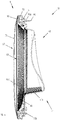
Figure 4 shows the door assembly ofFigure 2 sectioned along line IV°-IV°; -
Figure 5 shows a perspective view of the door assembly offigure 2 in a disassembled configuration; -
Figure 6 shows the door assembly in the disassembled configuration offigure 5 from another point of view; -
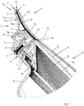
Figure 7 shows a partial view of the door assembly ofFigure 2 sectioned along line VII°-VII°; -
Figure 8 shows a partial view of the door assembly ofFigure 2 sectioned along line VIII°-VIII°; -
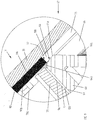
Figure 9 shows an enlarged view of a detail ofFigure 7 ; -
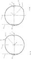
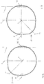
Figures 10a-10d show plan views of different configurations of the door assembly of the invention; -
Figures 11a-11d show perspective rear views of the door assembly of the invention corresponding to the different configurations represented inFigures 10a-10d . - The present invention has proved to be particularly advantageous when applied to a laundry dryer, as described below. In any case, it should be underlined that the present invention is not limited to laundry dryers. On the contrary, the present invention can be conveniently applied to laundry washing machines or washer-dryers (i.e. laundry washing machines which can also dry laundry).
- With reference to
fig. 1 an embodiment of a laundry treating machine realized according to the present invention is globally indicated with 1. In this preferred embodiment, thelaundry treating machine 1 is a laundry dryer, however the present teaching can be applied to laundry washing machines or washer-dryers as well. - The
dryer 1 comprises anouter box casing 7 preferably but not necessarily parallelepiped-shaped, and a treatment chamber, such as a drum (not visible in the Figure), for example having the shape of a hollow cylinder, for housing the laundry and in general the clothes and garments to be dried and/or washed. - The drum is preferably contained into the
casing 7. In a preferred embodiment, the drum can rotate around a preferably horizontal axis (in alternative embodiments, rotation axis may be vertical or tilted). - Access to the drum is achieved for example via an
opening 4 formed on a wall of thecasing 7 itself.Opening 4 preferably faces drum and it is apt to be closed - or even sealed - by adoor assembly 10. - The
door assembly 10 is adapted to alternatively open and close thelaundry loading opening 4 of thedryer 1 and is advantageously pivotally mounted, for example hinged, and thus supported at thecasing 7 of themachine 1.Door assembly 10 can be preferably operated by ahandle 50, as better detailed below. Preferably, casing 7 generally includes afront wall 2 to which thedoor assembly 10 is pivotally mounted. - The
door assembly 10 can have two different operative positions or configurations: a closed position in which it is abutting against thefront wall 2 and an open position in which it is separated from thefront wall 2, with the exception of the connecting element (e.g. hinge) location. In order to move thedoor assembly 10 from the closed to the open configuration or vice-versa, handle 50 is used. -
Handle 50 preferably belongs to a system which may be named "pull-to-open" door opening system: thedoor assembly 10 is provided with alatch 19 and thecasing 7, preferably thefront wall 2, is provided with a latch retaining mechanism (not shown) that includes a mobile part which is configured to be movable between a retaining position, in which it engages thelatch 19 so as to retain thedoor assembly 10 in the closed condition, and an opening position in which it releases thelatch 19 so as to allow the opening of thedoor assembly 10. The mobile part of the latch allows the releasing of the latch when a releasing force is applied which is greater than a threshold force. Thedoor assembly 10 is therefore opened by pulling it outwards with enough force and can be closed by pushing it towards the inside of the treatment chamber. - The
door assembly 10 preferably comprises arear frame 5, afront frame 6 arranged on afront side 5a of therear frame 5, aclosing element 40 and acovering element 60. The closingelement 40 is interposed between therear frame 5 and thefront frame 6 and the coveringelement 60 is interposed between the closingelement 40 and thefront frame 6. The coveringelement 60 at least partly covers theclosing element 40. - The
rear frame 5 is defined as the portion of the door assembly 10 a side of which, calledrear side 5b, is substantially in contact with, or immediately in front of, thecasing 7 when thedoor assembly 10 is in the closed operative position, while thefront frame 6 is defined as the portion of thedoor assembly 10 arranged outwardly when thedoor assembly 10 is closed ontocasing 7, i.e. it faces a direction opposite to thecasing 7. - The
rear frame 5 includes a rear frameinner edge 8a defining arear aperture 8. Thefront frame 6 preferably comprises afront supporting structure 70 and acap element 33. - The
front supporting structure 70 preferably has afront side 70a, arear side 70b and aninner edge 9a defining afront aperture 9. - The
cap element 33 is at least partially transparent and overlays thefront side 70a of thefront supporting structure 70 and extends over thefront aperture 9. Thecap element 33 has arear side 33b and a front side 33a, the latter forming the front surface of thedoor assembly 10. - Transparency allows light to pass through the
cap element 33 so that bodies situated behind can be seen. - The
cap element 33, apart from maintaining its at least partial transparency, may also comprise further aesthetic characteristics, such as coloured areas, images, areas with different degree of transparency, etc. - The
apertures casing 7 during the treatment cycles, in particular when both theclosing element 40 and thecap element 33 are at least partially transparent. - Rear and
front frames rear frame 5 and thefront supporting structure 70, are therefore so mounted that the twoapertures - Preferably, rear and
front frames apertures - Preferably, rear and
front frames front apertures door assembly 10 have an arbitrary geometrical shape, for example can be substantially polygonal, such as rectangular, quadratic, triangular, or elliptic when a front view of the same is considered. - Preferably, rear and
front frames front apertures - In the preferred embodiment of
door assembly 10, therear aperture 8 in therear frame 5 is closed by the closingelement 40. - The closing
element 40 is preferably at least partially transparent. - The closing
element 40 is preferably made of plastic and even more preferably it is made of a transparent, or at least semi-transparent, plastic material. The closingelement 40 can however be made of glass. - In this embodiment, the closing
element 40 is also partially covered by thecap element 33. - In the
dryer 1, the temperature of the drying air can reach rather high values, thus theclosing element 40 can also reach a substantially elevated temperature which can harm the user in case of contact between a user's body part and theclosing element 40. In order to avoid this drawback, a protective element is interposed between the user and theclosing element 40. This protective element is thecap element 33. - Analogously, in a washing machine, which is a possible non-depicted embodiment of
machine 1, the temperature of the water can often reach rather high values, thus the closing element can also reach a substantially elevated temperature that can harm the user in case of contact between a user's body part and the closing element. In order to avoid this drawback, a protective element is interposed between the user and the closing element, i.e. a protective cap element. In a washing machine the closing element is preferably made of glass. The closingelement 40 preferably has a bowl shape. In general, preferably, the closingelement 40 is shaped so as aportion thereof 41 protrudes within theopening 4 of thefront wall 2 ofdryer 1. - In a preferred embodiment illustrated and described herewith, the protruding
portion 41 preferably comprises a substantially flat horizontal portion 41a which, when thedoor assembly 10 is in the closed operative position, is arranged above a filter arrangement of the dryer (not shown) typically arranged downwardly in close proximity of, and accessible from theopening 4, inside thecasing 7. - As said above, the covering
element 60 is interposed between the closingelement 40 and thefront frame 6, preferably between the closingelement 40 and the supportingstructure 70 of thefront frame 6. - The covering
element 60 is opportunely shaped so as to at least partly cover theclosing element 40. - The covering
element 60 is provided for keeping theclosing element 40 in the correct position in the door assembly and, preferably, has the function of improving the aesthetic appearance of thedryer 1, as better explained below. The coveringelement 60 and theclosing element 40 are preferably sandwiched between therear frame 5 and the supportingstructure 70 of thefront frame 6 and kept firmly in position therebetween. In the preferred embodiment illustrated in the figures, no fastening device is used. In further preferred embodiments of the invention, fastening devices may be provided for fixing the covering element and/or the closing element to the rear frame and/or to the supporting structure of the front frame, such as welding, screws, snap devices, etc. - The
rear frame 5 and thefront frame 6 are coupled one to the other, preferably in a removable manner, by means of a fastening device 200. In particular, therear frame 5 and the supportingstructure 70 of thefront frame 6 are coupled one to the other, preferably in a removable manner, by means of the fastening device 200. - The fastening device 200 preferably comprises
coupling elements 121 andcorresponding coupling counter-elements 122 formed in the supportingstructure 70 and therear frame 5, respectively. - In the depicted embodiment, said
coupling elements 121 extend from therear side 70b of the supportingstructure 70 while saidcoupling counter-elements 122 extend from thefront surface 5a of therear frame 5. - Preferably, each
coupling element 121 includes a protruding element. Preferably the protrudingelement 121 includes a tubular sleeve having an open end. Preferably, eachcoupling counter-element 122 includes a protruding element. Preferably the protrudingelement 121 includes a tubular sleeve having an open end. - It is desired that the dimensions of the sleeves are such that the
coupling elements 121 can be preferably inserted within thecoupling counter-elements 122 or vice-versa. - Fastening screws 25 are preferably inserted from
rear surface 5b ofrear frame 5 into the through-holes defined by coupling counter-elements 122 and then screwed into the tubular sleeves ofcoupling elements 121 to fix the supportingstructure 70 to therear frame 5. - In further preferred embodiments, the insertion of the coupling elements into the coupling counter-elements or vice-versa is obtained with interference so that, when a coupling element is inserted in a coupling counter element (or vice-versa) the removal requires the application of a non-negligible force, so that the possibility of accidental removals is minimized.
- Preferably, the
coupling elements 121 and couplingcounter-elements 122 are angularly spaced one from the other, even more preferably with a substantially constant spacing one from the other so that the contour of thedoor assembly 10 is provided with coupling elements and coupling counter-elements. - In the preferred embodiment illustrated in the figures, the
coupling elements 121 and thecoupling counter-elements 122 are twelve angularly spaced one from the other of an angle of 30°. - Advantageously, and according to a further preferred aspect of the present invention, the
rear frame 5 and thefront frame 6 can be assembled together in different reciprocal angular positions or, in particular, therear frame 5 and the supportingstructure 70 of thefront frame 6 can be assembled together in different reciprocal angular positions, as explained in detail later. - Assembling of the
rear frame 5 to thefront frame 6 is carried out by rotating therear frame 5 and thefront frame 6 reciprocally up to the desired reciprocal position, aligning thecoupling elements 121 to the coupling counter-elements 122 and fixing therear frame 5 to thefront frame 6 by screwing thescrews 25. In the preferred embodiment illustrated in the figures, therear frame 5 and thefront frame 6 can be assembled together in different reciprocal angular positions which differ of an adjustment angle AN of 30° one to the other. - In different embodiments, the adjustment angle AN may be differently set, for example increasing or decreasing the number of coupling elements and coupling counter-elements along the contour of the door assembly.
- The adjustment angle AN is preferably comprised between 0° and 180°.
- The covering
element 60 which is sandwiched between therear frame 5 and the supportingstructure 70 preferably peripherally comprisesholes 63, which are passed through by coupling elements 121 (protruding elements) of the supportingstructure 70. This arrangement has the function of supporting the coveringelement 60 and/or improving the centering of the coveringelement 60 and to avoid rotations of the same. - The covering
element 60 preferably comprises a shapedportion 67 which extends at least partly through thefront aperture 9 of the supportingstructure 70 of thefront frame 6. - The shaped
portion 67 preferably comprises an outermostfront side surface 64 which faces therear side 33b of thecap element 33. - The outermost
front side surface 64 of the shapedportion 67 represents the surface which is arranged most outwardly with respect to thecasing 7 when the door assembly is in its closed position. The outermostfront side surface 64 represents also the surface of the shapedportion 67 which the closest surface to therear side 33b of thecap element 33. - The outermost
front side surface 64 preferably extends between a radially inner border line 64a and a radially outer border line 64b. Inner border line 64a and outer border line 64b are preferably circular and the outermostfront side surface 64 is consequently preferably an annular rim. - The shaped
portion 67 further preferably comprises asecond surface 66 extending away from thefirst side surface 64 towards the closingelement 40. Preferably thesecond surface 66 is a tapered surface which ends rearwardly by forming a covering elementrear aperture 68 facing the closingelement 40. - The
second surface 66 therefore extends partially over the closingelement 40 which is partially visible through the covering elementrear aperture 68 when viewed laterally outwardly from thedoor assembly 10, i.e. from outside thecasing 7. - The tapered
second surface 66 preferably includes a plurality ofribs 66a facing the cap element rear side and at least partially visible through thecap element 33,such ribs 66a give a pleasant aesthetic appearance to thedoor assembly 10. Furthermore, the shapedportion 67 advantageously overlaps the peripheral zone of thefront side 5a of therear frame 5. Advantageously, the shapedportion 67 hides said peripheral zone of thefront side 5a of therear frame 5 and gives a better aesthetic appearance to thedoor assembly 10, covering all possible elements that are present in said peripheral zone of thefront side 5a of therear frame 5. - The covering
element 60 comprises anouter edge 69, preferably a substantially cylindrical edge, which delimits aseat 80 facing theinner edge 9a of thefront supporting structure 70 and receiving a portion thereof. - An
unfilled interspace 120 is preferably defined between theedge 69 of coveringelement 60 and theinner edge 9a of thefront supporting structure 70. - According to a preferred aspect of the invention, between the outermost
front side surface 64 of the shapedportion 67 of the coveringelement 60 and therear side 33b of the cap element 33 agap 100 is defined. - The outermost
front side surface 64 of the shapedportion 67 of the coveringelement 60 is therefore at a given distance from therear side 33b of thecap element 33. - Being the
cap element 33 at least partially transparent, the outermostfront side surface 64 of the shapedportion 67 is visible at a lower degree (as viewed from the front of the door assembly 10) compared to known system, where the outermost front side surface is in contact with the transparent cap element. Advantageously, the visibility of dust and/or dirt which accumulates over the outermostfront side surface 64 of the shapedportion 67 and/or scratches over the outermostfront side surface 64 of the shapedportion 67 caused by handling is minimized and, therefore, the aesthetic appearance of thedoor assembly 10 is improved. - The supporting
structure 70 comprises anouter edge 61 and thecap element 33 comprises anouter edge 62. - Preferably,
outer edge 62 of thecap element 33 matches in shape and sizeouter edge 61 of the supportingstructure 70.Outer edge 62 of thecap element 33 andouter edge 61 of the supportingstructure 70 defines the outer contour of thedoor assembly 10. - According to an aspect of the present invention, the
cap element 33 and the supportingstructure 70 preferably comprise asector handle 50 for thedoor assembly 10. More preferably, asector 150 is defined on theouter edge 62 of thecap element 33 and asector 151 is defined on theouter edge 61 of the supportingstructure 70. Saidsectors handle 50 for thedoor assembly 10. - In the preferred embodiment illustrated and described herewith, said
sector 150 of theouter edge 62 of thecap element 33 preferably comprises a portion of theouter edge 62 which projects from the remaining contour of thecap element 33, as a radial protrusion. -
Figure 2 shows thesector 150 embodied as a projecting portion, wherein the remaining contour RC of thecap element 33 is indicated with a dashed line RC. - In the preferred embodiment here illustrated, the contour RC is preferably circumferentially shaped and the
sector 150 embodied as a projecting portion is substantially and preferably defined by an annular rim portion. Preferably, the annular rim portion extends over an angle of about 90°. - The
sector 150 embodied as a projecting portion is preferably inclined relative to thefront wall 2 of thecasing 7, i.e. towards the volume surrounding thecabinet 7 of thedryer 1, so as to define a bulge in the overall contour of thecap element 33. Inclination of thesector 150 embodied as a projecting portion is better visible inFigure 7 . - Analogously, in the preferred embodiment illustrated and described herewith, said
sector 151 of theouter edge 61 of the supportingstructure 70 preferably comprises a portion of theouter edge 61 that projects from the remaining contour of the supportingstructure 70, as a radial protrusion. -
Figure 11a showssector 151 embodied as a projecting portion, wherein also the remaining contour RC' of the supportingstructure 70 is depicted. - In the preferred embodiment here illustrated, the contour RC' is preferably circumferentially shaped and the
sector 151 embodied as a projecting portion is substantially preferably defined by an annular rim portion. Preferably, the annular rim portion extends over the same angle (of about 90°) of theannular rim portion 150 of thecap element 33. - The
sector 151 embodied as a projecting portion is preferably inclined relative to thefront wall 2 of thecasing 7, i.e. towards the volume surrounding thecabinet 7 of thedryer 1, so as to define a bulge in the overall contour of the supportingstructure 70. Inclination ofsector 151 embodied as a projecting portion is better visible inFigure 7 . Theinner side 151a ofsector 151 embodied as a projecting portion preferably defines the gripping portion for user fingers. -
Sector 150 of thecap element 33 andsector 151 of the supportingstructure 70 which define saidhandle 50, as described above, are preferably defined by both a radial protrusion and a bulge in the overall contour of thecap element 33 and/or supportingstructure 70. - In different embodiments, nevertheless, the
sectors - Preferably, the
handle 50 is only provided as a gripping portion to open the door by simply pulling it or closing the door by simply pushing it. In other words, the pulling or pushing action will cause thelatch 19 to actuate a latch retaining mechanism provided in thecasing 7. In this way, thehandle 50, during opening and/or closing movement, does not perform any movement relative to therear frame 5 and/or the supportingstructure 70. - Preferably, according to the description above, the
handle 50 is defined only by the supportingstructure 70 and thecap element 33 of thedoor assembly 10. Realization of thehandle 50 as described above allows to reduce the complexity of thedoor assembly 10 and therefore of thedryer 1. - In alternative embodiments the complexity of the
door assembly 10 can be further reduced by embodying thehandle 50 either on thefront supporting structure 70 or on thecap element 33. - Preferably, the handle is delimited by a radially outer edge of the front supporting structure and/or the cap element wherein said radially outer edge extends, for the most part thereof, in a circular path around a longitudinal axis (X) of the door assembly at a first distance therefrom, and a portion of said radially outer edge extends around the longitudinal axis (X) of the door assembly at a second distance therefrom, said second distance being greater than the first distance.
- This determines a simple structural construction for the assembly which reduces manufacturing costs of the assembly and of the dryer compared to known systems.
- According to a further preferred aspect of the present invention, an
opaque element 90 is arranged between the supportingstructure 70 and thecap element 33. - Opacity does not allow or highly reduces an incident light to pass through the
opaque element 90 so that it is difficult, or impossible, for a viewer to see any object placed behind theopaque element 90. - Preferably, the
opaque element 90 is fixed to therear side 33b of thecap element 33, as depicted inFigures 7 and9 , and contribute to form thehandle 50.. - The
opaque element 90 preferably has, for the most part thereof, an annular shape and comprises a radiallyouter edge 71 and a radiallyinner edge 72. Theinner edge 72 preferably defines anaperture 73 for theopaque element 90, as indicated inFigure 9 . Theopaque element 90 is, for the most part thereof, substantially ring-shaped. Theouter edge 71 of theopaque element 90 is preferably, for the most part thereof, rounded-shaped. - In case the
cap element 33 is at least partially transparent, theopaque ring 90 is visible from outside, i.e. when viewed laterally outwardly from the door assembly 10 (i.e. according to the viewing direction indicated with "V" inFigures 7 and9 ). - As illustrated in
Figures 7 and8 , theouter edge 71 of theopaque ring 90 preferably borders theouter edge 62 of thecap element 33. Preferably, theouter edge 71 of theopaque ring 90 borders also theborder edge 62 of the projectingportion 150, as illustrated in particular inFigure 7 . - In a preferred embodiment of the invention, the
opaque ring 90 is made of a plastic material and is over-molded on therear side 33b of thecap element 33 to preferably define a complete, integral, unitary body therewith. - In different embodiments, the opaque ring may be differently fixed to the cap element in order to define a completed, integral, unitary body therewith, for example by glueing.
- Preferably, the
opaque ring 90 and thecap element 33 are connected to thefront side 70a of the supportingstructure 70. More preferably, theopaque ring 90 and thecap element 33 are fixedly connected to the supportingstructure 70 in order to define a complete, integral, unitary member. - Preferably, the
opaque ring 90 atrear side 90b thereof comprises one ormore ribs 35, facing the supportingstructure 70, the ends of which allow welding of theopaque ring 90 to the supportingstructure 70, for example through ultrasonic or vibration welding. - The unitary body including the
opaque ring 90 and thecap element 33 is therefore welded to the supportingstructure 70 via theopaque ring 90. - Preferably, the
opaque ring 90 atrear side 90b thereof also comprises centering means 36 comprisingpins 36a facing the supportingstructure 70 and apt to be received in holes 36b realized in the supportingstructure 70. Centering means 36 allow correct alignment ofopaque ring 90 to the supportingstructure 70 during manufacturing step, preferably during welding. - Preferably, the
opaque ring 90 overlaps the peripheral zone of thefront side 70a of the supportingstructure 70. Advantageously, theopaque ring 90 hides said peripheral zone of thefront side 70a of the supportingstructure 70, which is therefore not visible from outside. Advantageously and preferably, theopaque ring 90 also hidesribs 35 for connecting theopaque ring 90 to the supportingstructure 70. - The
opaque ring 90, therefore, not only gives a pleasant aesthetic appearance to thedoor assembly 10, but also covers all possible elements which are present in the peripheral zone of thefront side 70a of the supportingstructure 70 and/or in therear side 90b of theopaque ring 90. - In the preferred embodiment of the invention here illustrated and described, the
outer edge 62 of thecap element 33 extends radially outwardly with respect to theouter edge 71 of theopaque ring 90, as illustrated inFigures 7 and8 , i.e. a peripheral portion of thecap element 33 extends radially beyond theopaque ring 90. Furthermore, preferably, theouter edge 61 of the supportingstructure 70 also extends radially outwardly with respect to theouter edge 71 of theopaque ring 90, i.e. a peripheral portion of the supportingstructure 70 extends radially beyond theopaque ring 90. - Advantageously, in case the
cap element 33 is at least partially transparent, it is possible to see the peripheral zone of the supportingstructure 70 through the portion of thecap element 33 that extends beyond theopaque ring 90 when viewed laterally outwardly from thedoor assembly 10. - Also, advantageously, in case the
cap element 33 is at least partially transparent, it is possible to see theouter edge 71 of theopaque ring 90, through the portion of thecap element 33 which extends beyond theopaque ring 90 when viewed laterally outwardly from thedoor assembly 10. - This further gives a pleasant aesthetic appearance to the
door assembly 10, in particular when theouter edge 71 is rounded-shaped, as in the present preferred embodiment. - According to a further preferred aspect of the present invention, the
opaque element 90 at least partly fills thegap 100 defined between the outermostfront side surface 64 of the shapedportion 67 of the coveringelement 60 and therear side 33b of thecap element 33. - Preferably, as shown in
Figure 9 , theinner edge 72 of theopaque element 90 is located between the inner border line 64a and the outer border line 64b of the outermostfront side surface 64. - The
opaque element 90 therefore covers theinterspace 120 defined between theouter edge 69 of coveringelement 60 which delimits aseat 80 facing theinner edge 9a of thefront supporting structure 70 and receiving a portion thereof. Advantageously, theopaque ring 90 hides theinterspace 120, which is therefore not visible from outside. This not only provide a pleasant aesthetic appearance to thedoor assembly 10, but also prevents dust, moisture or other foreign matter from accumulating within theinterspace 120 and being visible through the cap element, and further avoids that connections of door assembly components, such as the front andrear frames - In a further preferred advantageous embodiment, not illustrated, the opaque element totally fills the gap defined between the outermost front side surface of the shaped portion of the covering element and the rear side of the cap element. Referring to
Figure 9 , this means that the radiallyinner edge 72 of theopaque element 90 is aligned to the radially inner border line 64a of the outermostfront side surface 64. - The opaque element therefore still covers the
interspace 120 defined between theouter edge 69 of coveringelement 60 and theinner edge 9a of thefront supporting structure 70. Advantageously, theopaque ring 90 hides theinterspace 120, which is therefore not visible from outside. This, again, not only gives a better aesthetic appearance to thedoor assembly 10, but also prevents dust, moisture or other foreign matter from accumulating within theinterspace 120 and being visible through the cap element, and further avoids that connections of door assembly components, such as the front andrear frames - In a further preferred advantageous embodiment, nevertheless, the opaque element may not fill the gap defined between the outermost front side surface of the shaped portion of the covering element and the rear side of the cap element. This means that the
inner edge 72 of theopaque element 90 is radially outer than the outer border line 64b of the outermostfront side surface 64. Similarly to the embodiments described above, also this embodiment of the invention avoids that connections of door assembly components, such as the front andrear frames - The
door assembly 10 is preferably provided with anactuator 95 which interacts with a safety device of the dryer 1 (not illustrated), preferably fixed to thecasing 7. Theactuator 95 preferably comprises a fin protruding from therear side 5b of therear frame 5. The protrudingfin 95 is apt to operate a switch of the safety device when thedoor assembly 10 is in the closed position. The safety device can therefore advantageously detect if thedoor assembly 10 is in the closed or in the opened position. - The protruding
fin 95 is preferably arranged at therear side 5b of therear frame 5 in a vertical upward position. - A
first seat 95a is preferably realized vertically upward at therear side 5b of therear frame 5 for the connection of thefin 95 thereto. - Furthermore, as illustrated in
Figures 4 and6 , asecond seat 95b is also preferably realized vertically downward at therear side 5b of therear frame 5. Thesecond seat 95b is also apt for the connection of thefin 95 thereto. Use of thesecond seat 95b will be better described later. - As said above, the
door assembly 10 is advantageously hinged and supported at thecasing 7 of themachine 1, preferably atfront wall 2 of thecasing 7. -
Door assembly 10, therefore, preferably comprises ahinge device 160 that is provided to pivot thedoor assembly 10 to thecasing 7 so that it can be opened by rotating it about a hinge axis H, or axis of opening H of thedoor assembly 10.Hinge device 160 may be any conventional hinge, preferably of the type that is not visible when thedoor assembly 10 is closed. - In the embodiment shown in the figures,
hinge device 160 preferably comprises abase portion 161 apt to be fixed to thefront wall 2 of the casing 7 (for example withscrews knuckles base portion 161 which receive a pivot pin (not visible). -
Knuckles door assembly 10. Preferably, therear frame 5 comprises twoapertures knuckles - Preferably, the covering
element 60 comprises twoseats knuckles - Preferably, the supporting
structure 70 comprises twoseats knuckles knuckles door assembly 10 is in its closed position. -
Knuckles opaque ring 90 preferably hides the same. - Preferably, the
latch 19 and thehinge device 160 are arranged at opposite side of thedoor assembly 10 and are preferably aligned along a center line C of thedoor assembly 10 substantially perpendicular to the axis of opening H of thedoor assembly 10. - A vertical median axis V is also defined as the axis parallel to the axis of opening H and passing through the geometrical center O of the
door assembly 10, which is a point of the longitudinal axis X of the door assembly. A conventional angular reference system is defined by the center line C and the vertical median axis V. The axes C and V identify four quadrants for thedoor assembly 10. - The
handle 50 of thedoor assembly 10 illustrated and described herewith is preferably arranged offset with respect to the center line C, preferably at an upper position thereof and preferably arranged in the first quadrant, i.e. between 0° and 90°. Advantageously, as said above, thehandle 50 extends over an angle of about 90° and its central portion is preferably centrally positioned in the first quadrant. This position is indicated with "L1" and it preferably forms an angle of 45° with respect to the center line C. - Reciprocal arrangement of the
handle 50 and of thehinge device 160 as described above, allows to obtain a left-swing configuration for thedoor assembly 10. - According to a further preferred aspect of the invention, the
door assembly 10 of the invention allows reversibility of the same, i.e. thedoor assembly 10 may be reversed from a left-swing configuration to a right-swing configuration or vice-versa. - Furthermore, according to a further preferred aspect of the invention, the
door assembly 10 of the invention allows positioning of thehandle 50 in a plurality of positions with respect to the center line C of thedoor assembly 10. -
Figures 10a and 10b illustrate two possible positions for thehandle 50 in the left-swing configuration of the door assembly 10 (whereinFigure 10a corresponds toFigure 2 ). -
Figures 10c and 10d illustrate two possible positions for thehandle 50 in the right-swing configuration of thedoor assembly 10. -
Figure 10a shows the left-swing configuration of thedoor assembly 10 according to the preferred embodiment above described with thehandle 50 arranged at an upper position with respect to the center line C (position L1). -
Figure 10b shows the left-swing configuration of thedoor assembly 10 with thehandle 50 arranged at a lower position with respect to the center line C (position L2). -
Figure 10c shows the right-swing configuration of thedoor assembly 10 with thehandle 50 arranged at an upper position with respect to the center line C (position L3). -
Figure 10d shows the right-swing configuration of thedoor assembly 10 with thehandle 50 arranged at a lower position with respect to the center line C (position L4). -
Figures 11a to 11d show the perspective views of the door assembly configurations illustrated inFigures 10a to 10d , respectively
Reversibility of thedoor assembly 10, from a left-swing configuration to a right-swing configuration or vice-versa, is obtained by disassembling thedoor assembly 10 from thecasing 7, preferably unscrewingscrews hinge device 160, rotating and repositioning thedoor assembly 10 in a position at 180° with respect to the original position and assembling thedoor assembly 10 to thecasing 7, preferably screwingscrews hinge device 160. - This can be appreciated, for example, by comparing
Figure 11a or 11b toFigure 11c or 11d . - Together with rotation of the
door assembly 10, the position of thefin 95 is also moved to another fin seat when passing from a left-swing configuration to a right-swing configuration. In particular, as can be appreciated by comparingFigure 11a or 11b toFigure 11c or 11d , thefin 95 is disconnected from thefirst seat 95a at therear side 5b of therear frame 5 and connected to thesecond seat 95b, which is formed in therear frame 5 in an opposite position relative to thefirst seat 95a. The position of thefin 95 relative to themachine cabinet 7 remains constant when passing from a left-swing configuration to a right-swing configuration. In this way, there is no necessity to change the position of the safety device, which is preferably fixed to thecasing 7. - Positioning of the
handle 50 in different positions is preferably obtained thanks to the fastening device 200 of thedoor assembly 10. - For example, in a left-swing configuration, in order to change the position of the
handle 50 as illustrated inFigures 10a and11a (upper offset position) to the position of thehandle 50 as illustrated inFigures 10b and11b (lower offset position), the following steps are performed: - unscrewing the fastening screws 25 and releasing the
front frame 6 from therear frame 5; - rotating the
front frame 6 with respect to therear frame 5 from the original position (upper offset position) to the new position (lower offset position), preferably by rotating thefront frame 6 clockwise of 90° with respect to therear frame 5 or by rotating therear frame 5 counterclockwise of 90° with respect to thefront frame 6; - screwing the fastening screws 25 to connect the
front frame 6 to therear frame 5 in the new position (lower offset position). - Analogously, in a right-swing configuration, in order to change the position of the
handle 50 as illustrated inFigures 10c and11c (upper offset position) to the position of thehandle 50 ofFigures 10d and11d (lower offset position), the following steps are performed: - unscrewing the fastening screws 25 and releasing the
front frame 6 from therear frame 5; - rotating the
front frame 6 with respect to therear frame 5 from the original position (upper offset position) to the new position (lower offset position), preferably rotating thefront frame 6 counterclockwise of 90° with respect to therear frame 5 or by rotating therear frame 5 clockwise of 90° with respect to thefront frame 6; - screwing the fastening screws 25 to connect the
front frame 6 to therear frame 5 in the new position (lower offset position). - In different preferred embodiments of the invention, the handle can be positioned in a higher number of different positions, for example by varying the number of coupling elements and coupling counter-elements along the contour of the door assembly, as explained above.
- It is to be noted that both when the
door assembly 10 is reversed from a left-swing configuration to a right-swing configuration or vice-versa, and when the position of thehandle 50 is changed, the positions of the coveringelement 60 and theclosing element 40 remain unaltered relative to thecabinet 7. - It has thus been shown that the present invention allows all the set objects to be achieved. In particular, it makes it possible to provide a laundry treating machine that makes it possible to reduce manufacturing time and costs compared to known technique.
- It is underlined that the dryer illustrated in the enclosed figures is of the front-loading type; however it is clear that the system according to the invention can be applied as well to a top-loading dryer, substantially without any modification. While the present invention has been described with reference to the particular embodiment shown in the figures, it should be noted that the present invention is not limited to the specific embodiment illustrated and described herein; on the contrary, further variants of the embodiment described herein fall within the scope of the present invention, which is defined in the claims.
Claims (16)
- A door assembly (10) for a laundry treatment machine (1), apt to open and/or close an opening (4) defined in a wall (2) of the laundry treatment machine (1), the door assembly (10) comprising:- a rear frame (5) forming a rear surface of the door assembly (10) apt to face said wall (2) when the door assembly (10) closes the opening (4), the rear frame (5) including a rear frame inner edge (8a) defining a rear aperture (8);- a closing element (40) connected to the rear frame (5) to close the rear aperture (8) of the rear frame (5);- a front frame (6) arranged on a front side (5a) of the rear frame (5) and comprising:wherein it comprises a fastening device (200) that allows either the front frame (6) or the rear frame (5) to be connected to said rear frame (5) or front frame (6) respectively, in at least a first and a second alternative positions, so that the handle (50) provided in the front frame (6) can be positioned in at least a first and second different positions relative to the rear frame (5) and/or the rear frame (5) can be positioned in at least a first and second different positions relative to the handle (50).- a front supporting structure (70) having an inner edge (9a) defining a front aperture (9);- an at least partially transparent cap element (33) overlaying a front side (70a) of the front supporting structure (70), and extending over the front aperture (9), the cap element (33) forming the front surface of the door assembly (10);- a handle (50) provided on the front supporting structure (70) and/or the cap element (33);the door assembly (10) further comprising:- a covering element (60), at least partly covering the closing element (40), interposed between the rear frame (5) and the front frame (6);
- The door assembly according to claim 1 wherein the fastening device (200) comprises coupling elements (121) and corresponding coupling counter-elements (122) formed in the front supporting structure (70) and the rear frame (5).
- The door assembly according to claim 2 wherein at least a portion of the coupling elements (121) is inserted within the coupling counter-elements (122) or vice-versa;
- The door assembly according to claim 2 or 3 wherein said coupling elements (121) extend from a rear side (70b) of the front supporting structure (70) and said coupling counter-elements (122) extend from a front surface (5a) of the rear frame (5), each coupling element (121) or each coupling counter-element (122) including a protruding element.
- The door assembly according to claim 4 wherein the protruding element includes a tubular sleeve having an open end.
- The door assembly according to claim 5 wherein fastening screws (25) are inserted from the rear surface (5b) of rear frame (5) into through-holes defined by coupling counter-elements (122) and are screwed into the tubular sleeves of coupling elements (121) to fix the front supporting structure (70) to the rear frame (5).
- The door assembly according to any claim 2 to 4 wherein the insertion of the coupling elements (121) into the coupling counter-elements (122) or vice-versa is obtained with interference so that, when a coupling element (121) is inserted in a coupling counter element (122), or vice-versa, the removal requires the application of an extracting force.
- The door assembly according to any claim 2 to 7 wherein the covering element (60) comprises an outer edge (69), which delimits a seat (80) facing an inner edge (9a) of the front supporting structure (70) and receiving a portion thereof.
- The door assembly according to claim 8 wherein an interspace (120) is defined between the outer edge (69) of the covering element (60) and the inner edge (9a) of the front supporting structure (70).
- The door assembly according to claim 9 wherein said interspace (120) is covered by an opaque element (90) arranged at a rear side (33b) of the cap element (33).
- The door assembly according to any claim 2 to 10 wherein the covering element (60) is sandwiched between the rear frame (5) and the front supporting structure (70) and comprises holes (63), which are passed through by coupling elements (121) of the front supporting structure (70) so as to center the covering element 60 and to avoid rotations of the same.
- The door assembly according to any preceding claim, wherein the first and second alternative positions are obtained by rotating reciprocally the front frame (6) and the rear frame (5) by an adjustment angle (AN) comprised between 0° and 180°.
- The door assembly according to any of the preceding claims, wherein the first and/or the second position of said handle (50) is located at a given angle between 0° and 90° from a center line (C) of the door assembly substantially perpendicular to an axis of opening of the door assembly.
- The door assembly according to any of the preceding claims, wherein the handle (50) is delimited by a radially outer edge (61) of the front supporting structure (70) and/or the cap element (33) wherein said radially outer edge (61) extends, for the most part thereof, in a circular path around a longitudinal axis (X) of the door assembly (10) at a first distance therefrom, and a portion of said radially outer edge (61) extends around the longitudinal axis (X) of the door assembly (10) at a second distance therefrom, said second distance being greater than the first distance.
- A laundry treatment device comprising:- a casing (7) containing a treatment chamber for receiving a laundry load to be treated;- a front wall (2) covering a side of said casing (7), said front wall (2) including an opening (4) for accessing said treatment chamber;- a door assembly (10) associated to said casing (7) for opening and/or closing said opening (4), said door assembly (10) having the features according to one or more of claims from 1 to 14.
- Method to modify the position of a handle (50) in a door assembly (10) associated to a laundry treatment device, said door assembly (10) comprising:- a rear frame (5) forming a rear surface of the door assembly (10) apt to face said wall (2) when the door assembly (10) closes the opening (4), the rear frame (5) including a rear frame inner edge (8a) defining a rear aperture (8);- a closing element (40) connectable to the rear frame (5) to close the rear aperture (8) of the rear frame (5);- a front frame (6) arranged on a front side (5a) of the rear frame (5) and comprising:the door assembly (10) further comprising:- a front supporting structure (70) having an inner edge (9a) defining a front aperture (9);- an at least partially transparent cap element (33) overlaying a front side (70a) of the front supporting structure (70), and extending over the front aperture (9), the cap element (33) forming the front surface of the door assembly (10);- a handle (50) provided on the front supporting structure (70) and/or the cap element (33);- a covering element (60), at least partly covering the closing element (40), interposed between the rear frame (5) and the front frame (6);the door assembly (10) comprising a fastening device (200) that allows reciprocal connection of the rear frame (5) and the front frame (6) in a removable manner;
the method comprising the steps of:- operating the fastening device (200) to release the front frame (6) from the rear frame (5);- rotating the front frame (6) with respect to the rear frame (5) from a first position to a second position or rotating the rear frame (5) with respect to the front frame (6) from a first position to a second position,- arranging the covering element (60) and the closing element (40) such that they remain in an unaltered position relative to a cabinet (7) of the laundry treatment device, and- operating the fastening device (200) to connect the front frame (6) to the rear frame (5) in the second position.
Priority Applications (2)
| Application Number | Priority Date | Filing Date | Title |
|---|---|---|---|
| PL16199838.0T PL3323928T3 (en) | 2016-11-21 | 2016-11-21 | A door assembly for a laundry treating machine and a method to modify the position of a handle in said door assembly |
| EP16199838.0A EP3323928B1 (en) | 2016-11-21 | 2016-11-21 | A door assembly for a laundry treating machine and a method to modify the position of a handle in said door assembly |
Applications Claiming Priority (1)
| Application Number | Priority Date | Filing Date | Title |
|---|---|---|---|
| EP16199838.0A EP3323928B1 (en) | 2016-11-21 | 2016-11-21 | A door assembly for a laundry treating machine and a method to modify the position of a handle in said door assembly |
Publications (2)
| Publication Number | Publication Date |
|---|---|
| EP3323928A1 true EP3323928A1 (en) | 2018-05-23 |
| EP3323928B1 EP3323928B1 (en) | 2023-08-30 |
Family
ID=57354288
Family Applications (1)
| Application Number | Title | Priority Date | Filing Date |
|---|---|---|---|
| EP16199838.0A Active EP3323928B1 (en) | 2016-11-21 | 2016-11-21 | A door assembly for a laundry treating machine and a method to modify the position of a handle in said door assembly |
Country Status (2)
| Country | Link |
|---|---|
| EP (1) | EP3323928B1 (en) |
| PL (1) | PL3323928T3 (en) |
Cited By (4)
| Publication number | Priority date | Publication date | Assignee | Title |
|---|---|---|---|---|
| CN113279219A (en) * | 2020-02-19 | 2021-08-20 | Lg电子株式会社 | Clothes treating device |
| CN115679653A (en) * | 2021-07-21 | 2023-02-03 | 青岛海尔洗涤电器有限公司 | Clothes processing device and door body thereof |
| EP4283035A1 (en) * | 2022-05-24 | 2023-11-29 | BSH Hausgeräte GmbH | Laundry care appliance for the care of objects |
| DE102022205165A1 (en) | 2022-05-24 | 2023-11-30 | BSH Hausgeräte GmbH | Laundry care device for caring for items |
Citations (4)
| Publication number | Priority date | Publication date | Assignee | Title |
|---|---|---|---|---|
| US20070075614A1 (en) * | 2005-09-30 | 2007-04-05 | Calmeise Randall W | Methods and apparatus for a home appliance having a door |
| US20110025178A1 (en) * | 2009-07-30 | 2011-02-03 | Bsh Home Appliances Corporation | Door frame for a household appliance door |
| EP3034677A1 (en) * | 2014-12-19 | 2016-06-22 | Electrolux Appliances Aktiebolag | Door assembly for laundry treatment apparatus |
| WO2016135285A1 (en) * | 2015-02-27 | 2016-09-01 | Electrolux Appliances Aktiebolag | Laundry drying machine |
-
2016
- 2016-11-21 PL PL16199838.0T patent/PL3323928T3/en unknown
- 2016-11-21 EP EP16199838.0A patent/EP3323928B1/en active Active
Patent Citations (4)
| Publication number | Priority date | Publication date | Assignee | Title |
|---|---|---|---|---|
| US20070075614A1 (en) * | 2005-09-30 | 2007-04-05 | Calmeise Randall W | Methods and apparatus for a home appliance having a door |
| US20110025178A1 (en) * | 2009-07-30 | 2011-02-03 | Bsh Home Appliances Corporation | Door frame for a household appliance door |
| EP3034677A1 (en) * | 2014-12-19 | 2016-06-22 | Electrolux Appliances Aktiebolag | Door assembly for laundry treatment apparatus |
| WO2016135285A1 (en) * | 2015-02-27 | 2016-09-01 | Electrolux Appliances Aktiebolag | Laundry drying machine |
Cited By (5)
| Publication number | Priority date | Publication date | Assignee | Title |
|---|---|---|---|---|
| CN113279219A (en) * | 2020-02-19 | 2021-08-20 | Lg电子株式会社 | Clothes treating device |
| CN113279219B (en) * | 2020-02-19 | 2024-06-07 | Lg电子株式会社 | Clothes treating apparatus |
| CN115679653A (en) * | 2021-07-21 | 2023-02-03 | 青岛海尔洗涤电器有限公司 | Clothes processing device and door body thereof |
| EP4283035A1 (en) * | 2022-05-24 | 2023-11-29 | BSH Hausgeräte GmbH | Laundry care appliance for the care of objects |
| DE102022205165A1 (en) | 2022-05-24 | 2023-11-30 | BSH Hausgeräte GmbH | Laundry care device for caring for items |
Also Published As
| Publication number | Publication date |
|---|---|
| PL3323928T3 (en) | 2024-02-26 |
| EP3323928B1 (en) | 2023-08-30 |
Similar Documents
| Publication | Publication Date | Title |
|---|---|---|
| EP3323929B1 (en) | A door assembly for a laundry treatment machine | |
| EP2843105B1 (en) | A door assembly for a laundry treatment device and method of operation | |
| JP5492137B2 (en) | Drum type washer / dryer | |
| EP3181750B1 (en) | Laundry treatment device with door assembly | |
| EP3323928B1 (en) | A door assembly for a laundry treating machine and a method to modify the position of a handle in said door assembly | |
| US10640907B2 (en) | Laundry treatment machine | |
| US20140319983A1 (en) | Door assembly and clothes treatment apparatus having the same | |
| EP2843104B1 (en) | Door assembly for a laundry treatment device | |
| JP6184438B2 (en) | Drum type washer / dryer | |
| EP2843107B1 (en) | Laundry treatment device with a door assembly | |
| EP3323927B1 (en) | A door assembly for a laundry treating machine | |
| AU2016223373A1 (en) | Laundry drying machine | |
| EP3339499B1 (en) | Laundry dryer equipped with a door assembly | |
| EP2843109B1 (en) | Laundry treatment machine | |
| JP6568550B2 (en) | Drum washing machine | |
| JP5731035B2 (en) | Drum-type washing machine and drum-type washing machine | |
| EP2843110A1 (en) | Laundry treatment machine | |
| EP3617385B1 (en) | A door for washing and/or drying machines | |
| JP2018117889A (en) | Clothing processing equipment | |
| US20230033602A1 (en) | Laundry device | |
| JP2023047824A (en) | washing machine |
Legal Events
| Date | Code | Title | Description |
|---|---|---|---|
| PUAI | Public reference made under article 153(3) epc to a published international application that has entered the european phase |
Free format text: ORIGINAL CODE: 0009012 |
|
| STAA | Information on the status of an ep patent application or granted ep patent |
Free format text: STATUS: THE APPLICATION HAS BEEN PUBLISHED |
|
| AK | Designated contracting states |
Kind code of ref document: A1 Designated state(s): AL AT BE BG CH CY CZ DE DK EE ES FI FR GB GR HR HU IE IS IT LI LT LU LV MC MK MT NL NO PL PT RO RS SE SI SK SM TR |
|
| AX | Request for extension of the european patent |
Extension state: BA ME |
|
| STAA | Information on the status of an ep patent application or granted ep patent |
Free format text: STATUS: REQUEST FOR EXAMINATION WAS MADE |
|
| 17P | Request for examination filed |
Effective date: 20181123 |
|
| RBV | Designated contracting states (corrected) |
Designated state(s): AL AT BE BG CH CY CZ DE DK EE ES FI FR GB GR HR HU IE IS IT LI LT LU LV MC MK MT NL NO PL PT RO RS SE SI SK SM TR |
|
| STAA | Information on the status of an ep patent application or granted ep patent |
Free format text: STATUS: EXAMINATION IS IN PROGRESS |
|
| 17Q | First examination report despatched |
Effective date: 20200717 |
|
| GRAP | Despatch of communication of intention to grant a patent |
Free format text: ORIGINAL CODE: EPIDOSNIGR1 |
|
| STAA | Information on the status of an ep patent application or granted ep patent |
Free format text: STATUS: GRANT OF PATENT IS INTENDED |
|
| RIC1 | Information provided on ipc code assigned before grant |
Ipc: D06F 37/42 20060101ALN20230316BHEP Ipc: D06F 58/04 20060101ALI20230316BHEP Ipc: D06F 39/14 20060101AFI20230316BHEP |
|
| INTG | Intention to grant announced |
Effective date: 20230405 |
|
| GRAS | Grant fee paid |
Free format text: ORIGINAL CODE: EPIDOSNIGR3 |
|
| GRAA | (expected) grant |
Free format text: ORIGINAL CODE: 0009210 |
|
| STAA | Information on the status of an ep patent application or granted ep patent |
Free format text: STATUS: THE PATENT HAS BEEN GRANTED |
|
| AK | Designated contracting states |
Kind code of ref document: B1 Designated state(s): AL AT BE BG CH CY CZ DE DK EE ES FI FR GB GR HR HU IE IS IT LI LT LU LV MC MK MT NL NO PL PT RO RS SE SI SK SM TR |
|
| REG | Reference to a national code |
Ref country code: GB Ref legal event code: FG4D |
|
| REG | Reference to a national code |
Ref country code: CH Ref legal event code: EP |
|
| REG | Reference to a national code |
Ref country code: DE Ref legal event code: R096 Ref document number: 602016082267 Country of ref document: DE |
|
| REG | Reference to a national code |
Ref country code: IE Ref legal event code: FG4D |
|
| P01 | Opt-out of the competence of the unified patent court (upc) registered |
Effective date: 20230901 |
|
| REG | Reference to a national code |
Ref country code: LT Ref legal event code: MG9D |
|
| REG | Reference to a national code |
Ref country code: NL Ref legal event code: MP Effective date: 20230830 |
|
| REG | Reference to a national code |
Ref country code: AT Ref legal event code: MK05 Ref document number: 1605578 Country of ref document: AT Kind code of ref document: T Effective date: 20230830 |
|
| PG25 | Lapsed in a contracting state [announced via postgrant information from national office to epo] |
Ref country code: GR Free format text: LAPSE BECAUSE OF FAILURE TO SUBMIT A TRANSLATION OF THE DESCRIPTION OR TO PAY THE FEE WITHIN THE PRESCRIBED TIME-LIMIT Effective date: 20231201 |
|
| PG25 | Lapsed in a contracting state [announced via postgrant information from national office to epo] |
Ref country code: IS Free format text: LAPSE BECAUSE OF FAILURE TO SUBMIT A TRANSLATION OF THE DESCRIPTION OR TO PAY THE FEE WITHIN THE PRESCRIBED TIME-LIMIT Effective date: 20231230 |
|
| PG25 | Lapsed in a contracting state [announced via postgrant information from national office to epo] |
Ref country code: SE Free format text: LAPSE BECAUSE OF FAILURE TO SUBMIT A TRANSLATION OF THE DESCRIPTION OR TO PAY THE FEE WITHIN THE PRESCRIBED TIME-LIMIT Effective date: 20230830 Ref country code: RS Free format text: LAPSE BECAUSE OF FAILURE TO SUBMIT A TRANSLATION OF THE DESCRIPTION OR TO PAY THE FEE WITHIN THE PRESCRIBED TIME-LIMIT Effective date: 20230830 Ref country code: NO Free format text: LAPSE BECAUSE OF FAILURE TO SUBMIT A TRANSLATION OF THE DESCRIPTION OR TO PAY THE FEE WITHIN THE PRESCRIBED TIME-LIMIT Effective date: 20231130 Ref country code: LV Free format text: LAPSE BECAUSE OF FAILURE TO SUBMIT A TRANSLATION OF THE DESCRIPTION OR TO PAY THE FEE WITHIN THE PRESCRIBED TIME-LIMIT Effective date: 20230830 Ref country code: LT Free format text: LAPSE BECAUSE OF FAILURE TO SUBMIT A TRANSLATION OF THE DESCRIPTION OR TO PAY THE FEE WITHIN THE PRESCRIBED TIME-LIMIT Effective date: 20230830 Ref country code: IS Free format text: LAPSE BECAUSE OF FAILURE TO SUBMIT A TRANSLATION OF THE DESCRIPTION OR TO PAY THE FEE WITHIN THE PRESCRIBED TIME-LIMIT Effective date: 20231230 Ref country code: HR Free format text: LAPSE BECAUSE OF FAILURE TO SUBMIT A TRANSLATION OF THE DESCRIPTION OR TO PAY THE FEE WITHIN THE PRESCRIBED TIME-LIMIT Effective date: 20230830 Ref country code: GR Free format text: LAPSE BECAUSE OF FAILURE TO SUBMIT A TRANSLATION OF THE DESCRIPTION OR TO PAY THE FEE WITHIN THE PRESCRIBED TIME-LIMIT Effective date: 20231201 Ref country code: FI Free format text: LAPSE BECAUSE OF FAILURE TO SUBMIT A TRANSLATION OF THE DESCRIPTION OR TO PAY THE FEE WITHIN THE PRESCRIBED TIME-LIMIT Effective date: 20230830 Ref country code: AT Free format text: LAPSE BECAUSE OF FAILURE TO SUBMIT A TRANSLATION OF THE DESCRIPTION OR TO PAY THE FEE WITHIN THE PRESCRIBED TIME-LIMIT Effective date: 20230830 |
|
| PG25 | Lapsed in a contracting state [announced via postgrant information from national office to epo] |
Ref country code: NL Free format text: LAPSE BECAUSE OF FAILURE TO SUBMIT A TRANSLATION OF THE DESCRIPTION OR TO PAY THE FEE WITHIN THE PRESCRIBED TIME-LIMIT Effective date: 20230830 |
|
| PG25 | Lapsed in a contracting state [announced via postgrant information from national office to epo] |
Ref country code: ES Free format text: LAPSE BECAUSE OF FAILURE TO SUBMIT A TRANSLATION OF THE DESCRIPTION OR TO PAY THE FEE WITHIN THE PRESCRIBED TIME-LIMIT Effective date: 20230830 |
|
| PG25 | Lapsed in a contracting state [announced via postgrant information from national office to epo] |
Ref country code: SM Free format text: LAPSE BECAUSE OF FAILURE TO SUBMIT A TRANSLATION OF THE DESCRIPTION OR TO PAY THE FEE WITHIN THE PRESCRIBED TIME-LIMIT Effective date: 20230830 Ref country code: RO Free format text: LAPSE BECAUSE OF FAILURE TO SUBMIT A TRANSLATION OF THE DESCRIPTION OR TO PAY THE FEE WITHIN THE PRESCRIBED TIME-LIMIT Effective date: 20230830 Ref country code: ES Free format text: LAPSE BECAUSE OF FAILURE TO SUBMIT A TRANSLATION OF THE DESCRIPTION OR TO PAY THE FEE WITHIN THE PRESCRIBED TIME-LIMIT Effective date: 20230830 Ref country code: EE Free format text: LAPSE BECAUSE OF FAILURE TO SUBMIT A TRANSLATION OF THE DESCRIPTION OR TO PAY THE FEE WITHIN THE PRESCRIBED TIME-LIMIT Effective date: 20230830 Ref country code: DK Free format text: LAPSE BECAUSE OF FAILURE TO SUBMIT A TRANSLATION OF THE DESCRIPTION OR TO PAY THE FEE WITHIN THE PRESCRIBED TIME-LIMIT Effective date: 20230830 Ref country code: CZ Free format text: LAPSE BECAUSE OF FAILURE TO SUBMIT A TRANSLATION OF THE DESCRIPTION OR TO PAY THE FEE WITHIN THE PRESCRIBED TIME-LIMIT Effective date: 20230830 Ref country code: SK Free format text: LAPSE BECAUSE OF FAILURE TO SUBMIT A TRANSLATION OF THE DESCRIPTION OR TO PAY THE FEE WITHIN THE PRESCRIBED TIME-LIMIT Effective date: 20230830 Ref country code: PT Free format text: LAPSE BECAUSE OF FAILURE TO SUBMIT A TRANSLATION OF THE DESCRIPTION OR TO PAY THE FEE WITHIN THE PRESCRIBED TIME-LIMIT Effective date: 20240102 |
|
| PG25 | Lapsed in a contracting state [announced via postgrant information from national office to epo] |
Ref country code: IT Free format text: LAPSE BECAUSE OF FAILURE TO SUBMIT A TRANSLATION OF THE DESCRIPTION OR TO PAY THE FEE WITHIN THE PRESCRIBED TIME-LIMIT Effective date: 20230830 |
|
| REG | Reference to a national code |
Ref country code: DE Ref legal event code: R097 Ref document number: 602016082267 Country of ref document: DE |
|
| REG | Reference to a national code |
Ref country code: CH Ref legal event code: PL |
|
| PG25 | Lapsed in a contracting state [announced via postgrant information from national office to epo] |
Ref country code: MC Free format text: LAPSE BECAUSE OF FAILURE TO SUBMIT A TRANSLATION OF THE DESCRIPTION OR TO PAY THE FEE WITHIN THE PRESCRIBED TIME-LIMIT Effective date: 20230830 |
|
| PLBE | No opposition filed within time limit |
Free format text: ORIGINAL CODE: 0009261 |
|
| STAA | Information on the status of an ep patent application or granted ep patent |
Free format text: STATUS: NO OPPOSITION FILED WITHIN TIME LIMIT |
|
| PG25 | Lapsed in a contracting state [announced via postgrant information from national office to epo] |
Ref country code: LU Free format text: LAPSE BECAUSE OF NON-PAYMENT OF DUE FEES Effective date: 20231121 |
|
| PG25 | Lapsed in a contracting state [announced via postgrant information from national office to epo] |
Ref country code: CH Free format text: LAPSE BECAUSE OF NON-PAYMENT OF DUE FEES Effective date: 20231130 |
|
| PG25 | Lapsed in a contracting state [announced via postgrant information from national office to epo] |
Ref country code: MC Free format text: LAPSE BECAUSE OF FAILURE TO SUBMIT A TRANSLATION OF THE DESCRIPTION OR TO PAY THE FEE WITHIN THE PRESCRIBED TIME-LIMIT Effective date: 20230830 Ref country code: LU Free format text: LAPSE BECAUSE OF NON-PAYMENT OF DUE FEES Effective date: 20231121 Ref country code: CH Free format text: LAPSE BECAUSE OF NON-PAYMENT OF DUE FEES Effective date: 20231130 Ref country code: SI Free format text: LAPSE BECAUSE OF FAILURE TO SUBMIT A TRANSLATION OF THE DESCRIPTION OR TO PAY THE FEE WITHIN THE PRESCRIBED TIME-LIMIT Effective date: 20230830 |
|
| REG | Reference to a national code |
Ref country code: BE Ref legal event code: MM Effective date: 20231130 |
|
| 26N | No opposition filed |
Effective date: 20240603 |
|
| REG | Reference to a national code |
Ref country code: IE Ref legal event code: MM4A |
|
| PG25 | Lapsed in a contracting state [announced via postgrant information from national office to epo] |
Ref country code: IE Free format text: LAPSE BECAUSE OF NON-PAYMENT OF DUE FEES Effective date: 20231121 |
|
| PG25 | Lapsed in a contracting state [announced via postgrant information from national office to epo] |
Ref country code: BE Free format text: LAPSE BECAUSE OF NON-PAYMENT OF DUE FEES Effective date: 20231130 |
|
| PG25 | Lapsed in a contracting state [announced via postgrant information from national office to epo] |
Ref country code: IE Free format text: LAPSE BECAUSE OF NON-PAYMENT OF DUE FEES Effective date: 20231121 Ref country code: BE Free format text: LAPSE BECAUSE OF NON-PAYMENT OF DUE FEES Effective date: 20231130 |
|
| PG25 | Lapsed in a contracting state [announced via postgrant information from national office to epo] |
Ref country code: BG Free format text: LAPSE BECAUSE OF FAILURE TO SUBMIT A TRANSLATION OF THE DESCRIPTION OR TO PAY THE FEE WITHIN THE PRESCRIBED TIME-LIMIT Effective date: 20230830 |
|
| PG25 | Lapsed in a contracting state [announced via postgrant information from national office to epo] |
Ref country code: BG Free format text: LAPSE BECAUSE OF FAILURE TO SUBMIT A TRANSLATION OF THE DESCRIPTION OR TO PAY THE FEE WITHIN THE PRESCRIBED TIME-LIMIT Effective date: 20230830 |
|
| PG25 | Lapsed in a contracting state [announced via postgrant information from national office to epo] |
Ref country code: CY Free format text: LAPSE BECAUSE OF FAILURE TO SUBMIT A TRANSLATION OF THE DESCRIPTION OR TO PAY THE FEE WITHIN THE PRESCRIBED TIME-LIMIT; INVALID AB INITIO Effective date: 20161121 |
|
| PG25 | Lapsed in a contracting state [announced via postgrant information from national office to epo] |
Ref country code: HU Free format text: LAPSE BECAUSE OF FAILURE TO SUBMIT A TRANSLATION OF THE DESCRIPTION OR TO PAY THE FEE WITHIN THE PRESCRIBED TIME-LIMIT; INVALID AB INITIO Effective date: 20161121 |
|
| PG25 | Lapsed in a contracting state [announced via postgrant information from national office to epo] |
Ref country code: TR Free format text: LAPSE BECAUSE OF FAILURE TO SUBMIT A TRANSLATION OF THE DESCRIPTION OR TO PAY THE FEE WITHIN THE PRESCRIBED TIME-LIMIT Effective date: 20230830 |
|
| PGFP | Annual fee paid to national office [announced via postgrant information from national office to epo] |
Ref country code: DE Payment date: 20251126 Year of fee payment: 10 |
|
| PGFP | Annual fee paid to national office [announced via postgrant information from national office to epo] |
Ref country code: GB Payment date: 20251125 Year of fee payment: 10 |
|
| PGFP | Annual fee paid to national office [announced via postgrant information from national office to epo] |
Ref country code: FR Payment date: 20251124 Year of fee payment: 10 |
|
| PGFP | Annual fee paid to national office [announced via postgrant information from national office to epo] |
Ref country code: PL Payment date: 20251110 Year of fee payment: 10 |