EP3323716A1 - Aircraft airflow modification device and vortex generator arrangement for an aircraft - Google Patents
Aircraft airflow modification device and vortex generator arrangement for an aircraft Download PDFInfo
- Publication number
- EP3323716A1 EP3323716A1 EP16199770.5A EP16199770A EP3323716A1 EP 3323716 A1 EP3323716 A1 EP 3323716A1 EP 16199770 A EP16199770 A EP 16199770A EP 3323716 A1 EP3323716 A1 EP 3323716A1
- Authority
- EP
- European Patent Office
- Prior art keywords
- resiliently deformable
- state
- base member
- aircraft
- modification device
- Prior art date
- Legal status (The legal status is an assumption and is not a legal conclusion. Google has not performed a legal analysis and makes no representation as to the accuracy of the status listed.)
- Granted
Links
Images




Classifications
-
- B—PERFORMING OPERATIONS; TRANSPORTING
- B64—AIRCRAFT; AVIATION; COSMONAUTICS
- B64C—AEROPLANES; HELICOPTERS
- B64C23/00—Influencing air flow over aircraft surfaces, not otherwise provided for
- B64C23/06—Influencing air flow over aircraft surfaces, not otherwise provided for by generating vortices
-
- B—PERFORMING OPERATIONS; TRANSPORTING
- B64—AIRCRAFT; AVIATION; COSMONAUTICS
- B64C—AEROPLANES; HELICOPTERS
- B64C21/00—Influencing air flow over aircraft surfaces by affecting boundary layer flow
-
- B—PERFORMING OPERATIONS; TRANSPORTING
- B64—AIRCRAFT; AVIATION; COSMONAUTICS
- B64C—AEROPLANES; HELICOPTERS
- B64C3/00—Wings
- B64C3/38—Adjustment of complete wings or parts thereof
- B64C3/52—Warping
-
- B—PERFORMING OPERATIONS; TRANSPORTING
- B64—AIRCRAFT; AVIATION; COSMONAUTICS
- B64C—AEROPLANES; HELICOPTERS
- B64C9/00—Adjustable control surfaces or members, e.g. rudders
- B64C9/14—Adjustable control surfaces or members, e.g. rudders forming slots
- B64C9/16—Adjustable control surfaces or members, e.g. rudders forming slots at the rear of the wing
-
- Y—GENERAL TAGGING OF NEW TECHNOLOGICAL DEVELOPMENTS; GENERAL TAGGING OF CROSS-SECTIONAL TECHNOLOGIES SPANNING OVER SEVERAL SECTIONS OF THE IPC; TECHNICAL SUBJECTS COVERED BY FORMER USPC CROSS-REFERENCE ART COLLECTIONS [XRACs] AND DIGESTS
- Y02—TECHNOLOGIES OR APPLICATIONS FOR MITIGATION OR ADAPTATION AGAINST CLIMATE CHANGE
- Y02T—CLIMATE CHANGE MITIGATION TECHNOLOGIES RELATED TO TRANSPORTATION
- Y02T50/00—Aeronautics or air transport
- Y02T50/10—Drag reduction
Definitions
- the present technology relates to an aircraft airflow modification device and a vortex generator arrangement for an aircraft comprising an aircraft airflow modification device.
- the vertical tail plane of an aircraft and the vertical rudder mounted to the vertical tail plane provide a means to control a yawing moment for rotating the aircraft about its vertical or yawing axis. They therefore provide directional stability and control.
- the maximum yawing moment that can be generated by the rudder depends on the size of the rudder and the degree by which the rudder can be deflected about a rudder axis. In other words, more yawing moment can be generated with a larger rudder or a rudder that can be deflected by a greater angle. As the rudder can only be deflected by a limited angle to avoid stalling of the flow at the rudder, the maximum yawing moment is largely determined by the overall shape and surface area of the rudder and the vertical tail plane.
- a further object of the present technology is to provide a vortex generator arrangement that is less prone to failure or less costly to maintain by having few moving parts in its design.
- An embodiment of the present technology provides an aircraft airflow modification device comprising at least one resiliently deformable base member at least one resiliently deformable flap member that extends from the resiliently deformable base member, wherein deformation of the resiliently deformable base member from a first state to a second state results in corresponding deformation of the resiliently deformable flap member from a first state to a second state.
- the first state of the resiliently deformable flap member and the corresponding first state of the resiliently deformable base member may be unbuckled states, and the second state of the resiliently deformable flap member and the corresponding second state of the resiliently deformable base member may be buckled states.
- the resiliently deformable flap member or the resiliently deformable base member may be formed from at least one non-metallic material, metallic material or composite material.
- the lateral dimension of the resiliently deformable base member may be approximately 80 mm.
- the lateral dimension of the resiliently deformable flap member may be approximately 60 mm.
- the vertical dimension of the resiliently deformable flap member may be approximately 20 mm.
- the thickness of the resiliently deformable flap member may be approximately 1 mm.
- the resiliently deformable flap member may be integrally formed with the resiliently deformable base member.
- a further embodiment of the present technology provides a vortex generator arrangement () for a an aircraft comprising a section that defines an opening and a corresponding cavity, an aircraft airflow modification device disposed within the cavity further comprising a resiliently deformable flap member and a resiliently deformable base member , wherein the resiliently deformable flap member of the aircraft airflow modification device in a first state extends through the opening when the resiliently deformable base member is in a corresponding first state, and wherein the resiliently deformable flap member of the aircraft airflow modification device in a second state is retracted from the opening when the resiliently deformable base member is in a corresponding second state.
- the first state of the resiliently deformable flap member and the corresponding first state of the resiliently deformable base member may be unbuckled states.
- the second state of the resiliently deformable flap member and the corresponding second state of the resiliently deformable base member may be unbuckled states.
- the first state of the resiliently deformable flap member may be an unbuckled state and the corresponding first state of the resiliently deformable base member may be buckled states or vice versa.
- the vortex generator arrangement may further comprise at least one actuator arrangement configured to apply a force to the resiliently deformable base member of the aircraft airflow modification device so as to deform it from a first state to second state or vice versa.
- the actuator arrangement may be configured to provide a force substantially in the direction of the vertical axis of the resiliently deformable base member.
- the actuator arrangement may be configured to provide a force substantially in the direction of the lateral axis of the resiliently deformable base member.
- a further embodiment provides an aircraft with at least one vortex generator arrangement.
- the vortex generator arrangement may be installed on a surface assembly of an aircraft for example an engine pylon, a fuselage or a fairing.
- the surface assembly may be a lifting surface assembly for example a vertical or horizontal tail plane, a canard, a wingtip device, a wing or high-lift device.
- an aircraft 101 comprises a pair of lifting surface assemblies in the form of wings 103 that join into a fuselage 105.
- Each wing 103 comprises hinged control surfaces such as ailerons and spoilers (not shown), and high-lift devices such as flaps and slats (not shown).
- Each wing 103 carries an engine 107 that is mounted using a wing to engine pylon 108.
- the aircraft 101 comprises further lifting surface assemblies in the form a horizontal tail plane 109 and a vertical tail plane 111, each attached at the rear of the fuselage 105.
- the vertical tail plane 111 is provided with a hinged control surface in the form of a rudder 113.
- the aircraft 101 comprises other surface assemblies such a belly fairing 112 which fairs the wings 103 to the fuselage 105, and high-lift device fairings 114 that fair portions of the flaps (not shown) into the respective wing 103.
- the aircraft 101 further comprises a plurality of vortex generator arrangements 115 installed in the vertical tail plane 111.
- the deflection of each control surface, as well as each vortex generator arrangement 115, is controlled by at least one flight control unit 117.
- the flight control unit 117 receives inputs from at least one sensor unit 119 and commands deflections according to a predefined flight envelope stored on a medium (not shown) that is connected the flight control unit 117.
- each vortex generator arrangement 115 is set apart from an adjacent vortex generator arrangement 115 in a spanwise direction of the vertical tail plane 111.
- Each vortex generator arrangement 115 is installed in the main body 203 of the vertical tail plane 111 and has a chordwise position that is set forward of a foremost edge 201 of the rudder 113.
- an aircraft airflow modification device 301 comprising a resiliently deformable flap member 303 that is laminated to a resiliently deformable base member 305 so as to form a single integrally formed component i.e. it has no hinges or separate connector elements.
- the resiliently deformable flap member 303 In a first state the resiliently deformable flap member 303 is substantially planar and rectangular in shape and extends substantially perpendicular in the YZ plane from the resiliently deformable base member 305, which is also in a corresponding first state, such that a sidemost edge 307 of the resiliently deformable flap member 303 is approximately coincident with the YZ plane.
- the resiliently deformable flap member 303 is formed from 8 plies of co-cured GFRP laminate material that is stepped from down to 4 layers at its edge 307.
- An Epoxy/E-Glass composite may be used for each layer.
- the resiliently deformable flap member 303 may have a dimension He in the Z direction of at least 10 mm, but preferably it has a dimension Hf in the Z direction of 20 mm.
- the resiliently deformable flap member 303 may have a dimension Wf in the Y direction of at least 30mm, but preferably it has a dimension Wf in the Z direction of 60mm.
- the resiliently deformable flap member 303 may have a dimension Tf in the X direction of at least 0.5mm, but preferably it has a dimension Tf in the X direction of 1mm.
- the resiliently deformable base member 305 is formed of a rectangular GFRP laminated profile such that the resiliently deformable flap element 303 has a relatively low lateral stiffness when compared to the resiliently deformable based member 305.
- the resiliently deformable base member 305 may have a dimension Hb in the Z direction of at least 2 mm, but preferably it has a dimension Hb in the Z direction of 5 mm.
- the resiliently deformable base member 305 may have a dimension Wb in the Y direction of at least 60 mm (i.e. same Y dimension as the resiliently deformable flap member 303), but preferably it has a dimension Wb in the Y direction of 80mm.
- the resiliently deformable base member 305 preferably has a dimension Tb in the X direction of 20 mm.
- the resiliently deformable flap member 303 or the resiliently deformable base member 305 may be formed by any other suitable material such as non-metallic, metallic or composite material and further by any suitable means including but not limited to laying-up and curing the material, by additive layer manufacturing, or by machining, forming, casting, or moulding the material. Furthermore, the resiliently deformable flap member 303 and the resiliently deformable base member 305 may be integrally formed.
- the resiliently deformable flap member 303 may not be rectangular in shape and instead it may have a foremost or rearmost edge that is swept. It may instead be triangular in shape. Alternatively it may comprise edges which are curved. It may instead be semi-circular or semi-elliptical in shape.
- the aircraft airflow modification device 301 shown at the first state of figure 3A is shown in a second state in figure 3B .
- the resiliently deformable base member 305 undergoes uniaxial elastic bending to a second state, which results in unsymmetrical elastic buckling of the resiliently deformable flap member 303 to a corresponding second state.
- This is caused by lateral torsional buckling of the resiliently deformable flap member 303 that has a lower overall lateral stiffness compared to that of the resiliently deformable base member 305.
- its sidemost edge 307 is at an angle A relative to the YZ plane that is approximately perpendicular.
- the resiliently deformable flap element 303 is in an extended configuration when the first state is an unbuckled state and in a retracted configuration when the second state is a buckled state.
- the resiliently deformable base member 305 is unbuckled for the first state and buckled for the corresponding second state.
- the aircraft airflow modification may be configured and manufactured such that the resiliently deformable flap element 303 is extended and unbuckled in a first state that corresponds to a buckled first state of the resiliently deformable base member 305.
- each vortex generator arrangement 115 comprises a casing 401 that is overall substantially rectangular in shape; having an outer cover 403 that is defined by a section 405 that is substantially co-planar with the outermost surface (commonly also referred to as the outer mould line or OML) of the vertical tail plane 111 (not shown).
- OML outer mould line
- the casing 401 comprises a foremost wall 407 and a rearmost wall 409, each lying approximately parallel to the XZ plane, and a pair of sidewalls 411 413, each lying approximately parallel to the YZ plane, and an innermost wall 414 (not shown) lying approximately parallel to the XY plane and offset from the outer cover 403.
- the casing 401 is a unitary component formed from CFRP material. It may however be an assembly of two or more separate sub-components formed from the same material that are attached to one another by any suitable means such as by replaceable fasteners. Such an arrangement may be preferable for subsequent assembly and disassembly of the vortex generator arrangement 115.
- the casing 401 may also be formed by any other suitable non-metallic, metallic or composite material using any suitable manufacturing means such as additive layer manufacturing, machining, forming, casting, moulding, or lay-up and curing.
- a peripheral edge 417 of the outer cover 403 is configured so as to extend substantially perpendicular from the walls 407, 409, 411, 413 of the casing 401 so as to define an overhang 419 that is configured to attach to the corresponding peripheral edges 501(not shown) provided by the vertical tail plane 111.
- the overhang 419 extends substantially along the entire peripheral edge 417 i.e. along the front, rear and both side walls 407, 409, 411, 413 of the vortex generator arrangement 115.
- This overlapping arrangement may however not be continuous around the peripheral edge of the top cover 403.
- counter-sunk quick release fasteners (not shown) are used in combination with corresponding nut plates (not shown) affixed to the portions of the surrounding structure, to assemble the vortex generator arrangement 115 to the vertical tail plane 111.
- This provides system that is line replaceable, which is important for in-service operations, where a failed unit can be replaced quickly to prevent unnecessary delay during normal operation.
- it may form an integral part of the vertical tail plane 111 i.e. part of the cover of the vertical tail plane 111.
- the section 405 also defines an opening 421 in the outer cover 403 of the casing 401 to a corresponding cavity 423 within the casing 401 that is further defined by inner surfaces of the walls 407, 409, 411 and 413.
- the inner surfaces may be offset as shown or may lie in close proximity to the edges of the resiliently deformable flap member 303.
- the edge of the opening 421 may comprise a large radius or chamfer which is configured to improve the airflow passing over the cavity 423.
- the aircraft airflow modification device 301 that is supported by the foremost and rearmost walls 407 and 409 of the casing 401 and that comprises the resiliently deformable flap member 303, which in the first state shown in figure 4A extends through the opening 421.
- the resiliently deformable flap member 303 When the resiliently deformable flap member 303 is extended at a the first state during operation of the aircraft 101, a portion of the airflow 431 in proximity to the outer cover 403 is modified by the resiliently deformable flap member 303 so as to create one or more airflow vortices 433 that flows rearwards from the position of the vortex generator arrangement 115 and over the vertical tail plane 111and rudder 113.
- the vortex generator arrangement 115 of figure 4A is shown in a second configuration where the resiliently deformable flap member 303 of the aircraft airflow modification device 301 is retracted from the opening 421 when it is at a second buckled state and the resiliently deformable base member is at a corresponding second buckled state i.e. corresponding to the states shown in figure 3B .
- a known effect of vortices 433 in proximity to a lifting surface undergoing airflow separation is to delay the onset of airflow separation from the lifting surface even though such vortices 433 also create an associated amount of form drag and vortex drag. Despite of this drag penalty they are desirable in certain situations.
- a vertical tail plane 111 or rudder 113 are sized bearing in mind parameters such as surface area, airfoil section etc. so that they are capable of providing a sufficient yaw moment to control the aircraft 101when they are operated at maximum angles of incidence relative to the freestream airflow direction.
- the sizing of the vertical tail plane 111 and rudder 113 for these situations may take into account a certain amount of lift loss due to flow separation which may be present.
- flow separation loss can be reduced or removed completely when vortices 433 are introduced forwards (upstream) of the areas of the vertical tail plane 111 and rudder 113 that would otherwise exhibit flow separation at higher angles of incidence.
- the vortex generator arrangement 115 of the present technology is a means of achieving this, which in turn allows for a reduction in the size and therefore weight of the vertical tail plane 111 and rudder 113 overall, which is advantageous in terms of manufacturing and operating cost of the aircraft 101.
- the opening 423 may be further provided with a thin rupturable membrane configured to extend over the opening 423 in the plane of section 405 and fastened or glued to the outer cover 403.
- the rupturable membrane would provide an aerodynamic cover for the cavity 423 but be further configured to permanently rupture due to the resiliently deformable flap member 303 contacting it during the initial stages of its first extension so as not to inhibit the full extension or performance of the resiliently deformable flap member 303.
- the resiliently deformable flap member 303 of the airflow modification device 301 is not retracted entirely into the cavity but that it instead lies substantially parallel to the plane of section 405 when it is at a second buckled state and the resiliently deformable base member is at a corresponding second buckled state.
- the resiliently deformable flap member 303 would remain in the airflow in the retracted second state but not create any significant vortices 433 and associated drag. It may however create a level of form drag that would be acceptable.
- a further advantage of using a vortex generator arrangement 115 comprising such an aircraft airflow modification device 301 is that the aircraft airflow modification device 301 has no moving parts so that its design is simplified. It may therefore also have a lower probability of failure due to wear or due to seizing in the presence of contaminants such as ice, oil or dust. This may lead to the need for a lower number of vortex generator arrangements 115 therefore reducing complexity or lower costs as a result of longer maintenance inspection intervals.
- one or more vortex generator arrangements 115 may be placed elsewhere on the vertical tail plane 111 in order to enhance the aerodynamic performance, for example at a foremost "leading" edge portion of the vertical tail plane 111 or rudder 113. It should further be appreciated that one or more vortex generator arrangements 115 may be placed elsewhere on the aircraft 101 in proximity to any other lifting surface where suppression of flow separation may be desirable. For example one or more vortex generator arrangements 115 may be installed at a portion of the foremost edge or rearmost "trailing" edge of the wings 103, or of the horizontal stabilizers 109. Alternatively they may be installed on another surface assembly such as the pylon 108 or an engine 103.
- one or more vortex generator arrangements 115 may be used to improve aero acoustical performance of the aircraft 101.
- one or more vortex generator arrangements 115 may be positioned forward of (upstream) and in proximity to an aperture 110 defined by a portion of the outer surface of the aircraft 101, so as to generate one or more vortices 433 that may reduce audible Helm-Holtz induced frequencies from such an aperture 110.
- an airflow modification device 301 is installed within the cavity 423.
- a first end 502 and a second end 503 of the resiliently deformable base member 305 are each positioned within a respective slot 509 and 507 defined by the rearmost wall 409 and foremost wall 407, respectively, such that the airflow modification device 301 is supported at both ends.
- An actuator arrangement 510 comprising a, electrically powered linear actuator 511 and a coupling 513 are also installed within the cavity 423. It should be appreciated that the actuator arrangement may comprise any suitable alternative such as a rotary type actuator or piezo type actuator. The actuator may alternatively be hydraulically energized.
- a first end 515 of the linear actuator 511 has a lug and is pivotably mounted to a corresponding set of lugs provided by the innermost wall 414 of the cavity 423 with a clevis pin 519.
- a second end 521 if the linear actuator 511 comprises a lug that is pivotably connected via another clevis pin 523 to a set of lugs provided by the coupling 513.
- the coupling 525 is fixedly attached to a lower surface 527 of the resiliently deformable base member 305 at a position approximately at its mid-length in the Y direction.
- a universal ball joint type arrangement may alternatively be used instead of either of the pin arrangements used to connect the linear actuator 511 to the casing 401 or the coupling 525, which may permit a greater degree of freedom, if required.
- the resiliently deformable base member 305 When the actuator arrangement 510 is at a first position as shown in a figure 5A , the resiliently deformable base member 305 is in a first state which is a unbuckled state and the resiliently deformable flap member 303 is therefore in a corresponding first state that is also unbuckled. In this state, the resiliently deformable flap member 303 extends through the opening 421 and functions as a vortex generator in the presence of an airflow flowing over the vertical tail plane 111.
- the actuator arrangement 510 is actuated to second position, such that a force is provided substantially in the direction of the vertical axis of the resiliently deformable base member 305 such that the resiliently deformable base member 305 is deformed to a second state which is a buckled state and the resiliently deformable flap member 303 is therefore also deformed to a corresponding second state that is a buckled state.
- the resiliently deformable flap member 303 is retracted from the opening 421 such that the resiliently deformable flap member 303 extends substantially in the plane of the section 405 (i.e.
- the elastic energy stored within the aircraft airflow modification device 301 is sufficient to back drive the linear actuator 511 so as to restore the aircraft airflow modification device 301 from the buckled second state to the unbuckled first state.
- aircraft airflow modification device 301 may alternatively be actuated and deformed between first and second states by deformation of the surrounding structure acting on the resiliently deformable base member 305 or by pressure differences acting on the resiliently deformable flap member 303 due to the airflow external to the cavity, rather than by actuation of a particular types of powered actuator arrangements so far described.
- a gap 601 is provided between the side wall 413 of the casing 401 and the airflow modification device 301. Such a gap 601 may be preferable for providing a path for installing or replacing the actuator arrangement 510 or other internal components within the casing 401 or for carrying out maintenance or service inspections.
- the side wall 413 of the casing 401 may be configured such that the sidemost edge 309 of the resiliently deformable base member 305 substantially abuts the interior surface of the side wall 413, when it is in the first state and second state and that the side wall 413 of the casing 401 may also be configured to substantially abut the sidemost edge 307 of the resiliently deformable flap member 303 when it is in a buckled second state. It may be preferable to do so in order to prevent liquids and contaminants from collecting within the cavity 423.
- the coupling 513 substantially spans the resiliently deformable base member 305 in the X direction. This ensures that the load applied vertically by the actuator arrangement 510 in the Z direction is distributed evenly across the X dimension span of the resiliently deformable base member 305 via the coupling 525. Attaching the linear actuator 511 at the second end to the coupling 513 using a pivotal clevis pin 523 may allow for easier installation and replacement of the linear actuator 511 when required. The use of pivotal connections 519 and 523 in the actuator arrangement 510 ensures that bending loads are not applied to the resiliently deformable base member 305 when the vertical load is applied, which may cause unintended deformation of the aircraft airflow modification device 303.
- FIG 7A an alternative embodiment is shown.
- the vortex generator arrangement 115 of this embodiment is substantially the same as that shown in figure 4A .
- An airflow modification device 301 is installed within the cavity 423.
- the resiliently deformable base member 305 of the device is formed such that in its first unbuckled state it is overall slightly curved in shape in the positive Z direction, represented in the figure by the dashed line 701 and the upper and lower surfaces 702.
- a first end 709 of the resiliently deformable base member 305 is rounded in shape and is positioned within a corresponding first slot 509 which also has a corresponding round shape such that the first end 709 substantially conforms to the interior surface of the first slot 509.
- a second end 707 of the resiliently deformable base member 305 is positioned within a corresponding second slot 507 of similar corresponding shape.
- An actuator arrangement 710 is provided in the second slot 507.
- the actuator arrangement comprises a linear actuator 711.
- the linear actuator 711 is fixed at a first end 713 to the foremost wall 407 of the casing 401.
- a second end 715 of the linear actuator 711 is pivotally attached the second end 707 of the resiliently deformable base member 305 by a clevis pin 717.
- the actuator arrangement 710 is such that the resiliently deformable base member 305 can rotate relative to the second end 715 of the linear actuator 711 in a sense that is substantially parallel to the YZ plane.
- the resiliently deformable base member 305 When the actuator arrangement 710 is at a first position as shown in a figure 7A , the resiliently deformable base member 305 is in a first state which is a unbuckled state and the resiliently deformable flap member 303 is therefore in a corresponding first state that is also unbuckled. In this state, the resiliently deformable flap member 303 extends through the opening 421 and functions as a vortex generator in the presence of an airflow flowing over the vertical tail plane 111.
- the actuator arrangement 710 is actuated to second position, such that a force is provided substantially along the lateral axis (Y direction) of the resiliently deformable base member 305 such that the resiliently deformable base member 305 is deformed to a second state which is a buckled state and the resiliently deformable flap member 303 is therefore also deformed to a corresponding second state that is a buckled state.
- the resiliently deformable flap member 303 is retracted from the opening 421 such that the resiliently deformable flap member 303 extends substantially in the plane of the section 405 (i.e.
- the elastic energy stored within the aircraft airflow modification device 301 is sufficient to back drive the linear actuator 711 so as to restore the aircraft airflow modification device 301 from the buckled second state to the unbuckled first state.
- the casing 401 in the present embodiment does not need to have as big a cavity 423 due to the actuator arrangement 710 requiring a much shorter stroke to achieve the same amount of deformation of the aircraft airflow modification device 301.
- a piezo type actuator may be preferable for such an arrangement due to their power density is relatively high for a given size.
- inner wall 414 of the casing 401 is closer to the outer wall 403 and therefore shallower resulting in a vortex generator arrangement 115 of the present embodiment being much more compact.
- Such an arrangement may be preferable where the available internal space of the vertical tail plane 111 is limited and may particularly be required for outboard trailing edge regions of the vertical tail plane 111 or other lifting surfaces.
Landscapes
- Engineering & Computer Science (AREA)
- Aviation & Aerospace Engineering (AREA)
- Mechanical Engineering (AREA)
- Aerodynamic Tests, Hydrodynamic Tests, Wind Tunnels, And Water Tanks (AREA)
- Structures Of Non-Positive Displacement Pumps (AREA)
Abstract
Description
- The present technology relates to an aircraft airflow modification device and a vortex generator arrangement for an aircraft comprising an aircraft airflow modification device.
- The vertical tail plane of an aircraft and the vertical rudder mounted to the vertical tail plane provide a means to control a yawing moment for rotating the aircraft about its vertical or yawing axis. They therefore provide directional stability and control. The maximum yawing moment that can be generated by the rudder depends on the size of the rudder and the degree by which the rudder can be deflected about a rudder axis. In other words, more yawing moment can be generated with a larger rudder or a rudder that can be deflected by a greater angle. As the rudder can only be deflected by a limited angle to avoid stalling of the flow at the rudder, the maximum yawing moment is largely determined by the overall shape and surface area of the rudder and the vertical tail plane.
- Maximum yawing moment is never required under regular operating conditions, therefore most of the yawing moment that could be generated by the vertical rudder remains unused, which results in unnecessary aerodynamic drag and as drag increases, the fuel consumption increases, which reduces the maximum range of the aircraft. Therefore any unnecessary drag should be avoided.
- In view of the above it can be considered an object of the present technology to improve the flow by the vertical tail plane and the vertical rudder without having to increase the dimensions of the vertical tail plane. A further object of the present technology is to provide a vortex generator arrangement that is less prone to failure or less costly to maintain by having few moving parts in its design.
- An embodiment of the present technology provides an aircraft airflow modification device comprising at least one resiliently deformable base member at least one resiliently deformable flap member that extends from the resiliently deformable base member, wherein deformation of the resiliently deformable base member from a first state to a second state results in corresponding deformation of the resiliently deformable flap member from a first state to a second state.
- The first state of the resiliently deformable flap member and the corresponding first state of the resiliently deformable base member may be unbuckled states, and the second state of the resiliently deformable flap member and the corresponding second state of the resiliently deformable base member may be buckled states.
- The resiliently deformable flap member or the resiliently deformable base member may be formed from at least one non-metallic material, metallic material or composite material.
- The lateral dimension of the resiliently deformable base member may be approximately 80 mm. The lateral dimension of the resiliently deformable flap member may be approximately 60 mm. The vertical dimension of the resiliently deformable flap member may be approximately 20 mm. The thickness of the resiliently deformable flap member may be approximately 1 mm.
- The resiliently deformable flap member may be integrally formed with the resiliently deformable base member.
- A further embodiment of the present technology provides a vortex generator arrangement () for a an aircraft comprising a section that defines an opening and a corresponding cavity, an aircraft airflow modification device disposed within the cavity further comprising a resiliently deformable flap member and a resiliently deformable base member , wherein the resiliently deformable flap member of the aircraft airflow modification device in a first state extends through the opening when the resiliently deformable base member is in a corresponding first state, and wherein the resiliently deformable flap member of the aircraft airflow modification device in a second state is retracted from the opening when the resiliently deformable base member is in a corresponding second state.
- The first state of the resiliently deformable flap member and the corresponding first state of the resiliently deformable base member may be unbuckled states.
- The second state of the resiliently deformable flap member and the corresponding second state of the resiliently deformable base member may be unbuckled states. Alternatively, the first state of the resiliently deformable flap member may be an unbuckled state and the corresponding first state of the resiliently deformable base member may be buckled states or vice versa.
- The vortex generator arrangement may further comprise at least one actuator arrangement configured to apply a force to the resiliently deformable base member of the aircraft airflow modification device so as to deform it from a first state to second state or vice versa. The actuator arrangement may be configured to provide a force substantially in the direction of the vertical axis of the resiliently deformable base member. The actuator arrangement may be configured to provide a force substantially in the direction of the lateral axis of the resiliently deformable base member.
- A further embodiment provides an aircraft with at least one vortex generator arrangement. The vortex generator arrangement may be installed on a surface assembly of an aircraft for example an engine pylon, a fuselage or a fairing. The surface assembly may be a lifting surface assembly for example a vertical or horizontal tail plane, a canard, a wingtip device, a wing or high-lift device.
- Advantages of the present technology will now become apparent from the detailed description with appropriate reference to the accompanying drawings.
- Embodiments of the technology will now be described, by way of example only, with reference to the following drawings in which:
-
Figure 1 is a side view of an aircraft comprising a plurality of vortex generator arrangements and a system for operating the vortex generator arrangements; -
Figure 2 is a close-up view of the vertical tail plane of the aircraft offigure 1 showing the vortex generator arrangement positions in more detail; -
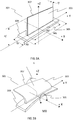
Figure 3A is an isometric view of an aircraft airflow modification device of one of the vortex generator arrangements offigure 1 and2 in a first state that is extended; -
Figure 3B is an isometric view of the aircraft airflow modification device offigure 3A in a second state that is retracted; -
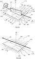
Figure 4A is an isometric view of one of the vortex generators arrangements offigure 1 and2 comprising an aircraft airflow modification device in a first state that is extended; -
Figure 4B is an isometric view of the vortex generator arrangement offigure 3B in a second state that is retracted; -
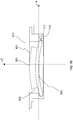
Figure 5A provides a side section view of thevortex generator arrangement 115 along the YZ plane indicated infigure 4A ; -
Figures 5B provides a side section view of thevortex generator arrangement 115 along the YZ plane indicated infigure 4B ; -
Figures 6A is a front sectional view of vortex generator arrangement offigure 4A through the plane XZ given infigure 4A ; -
Figure 6B is a front sectional view of vortex generator arrangement offigure 4B through the plane XZ given infigure 4B ; -
Figures 7A is a front sectional view of vortex generator arrangement offigure 4A , according to a further embodiment of the present technology; -
Figures 7B is a front sectional view of vortex generator arrangement offigure 4B , according to a further embodiment of the present technology. - With reference to
figure 1 , anaircraft 101 comprises a pair of lifting surface assemblies in the form ofwings 103 that join into afuselage 105. Eachwing 103 comprises hinged control surfaces such as ailerons and spoilers (not shown), and high-lift devices such as flaps and slats (not shown). Eachwing 103 carries anengine 107 that is mounted using a wing toengine pylon 108. Theaircraft 101 comprises further lifting surface assemblies in the form ahorizontal tail plane 109 and avertical tail plane 111, each attached at the rear of thefuselage 105. Thevertical tail plane 111 is provided with a hinged control surface in the form of arudder 113. Theaircraft 101 comprises other surface assemblies such a belly fairing 112 which fairs thewings 103 to thefuselage 105, and high-lift device fairings 114 that fair portions of the flaps (not shown) into therespective wing 103. - In the present embodiment, the
aircraft 101 further comprises a plurality ofvortex generator arrangements 115 installed in thevertical tail plane 111. The deflection of each control surface, as well as eachvortex generator arrangement 115, is controlled by at least oneflight control unit 117. Theflight control unit 117 receives inputs from at least onesensor unit 119 and commands deflections according to a predefined flight envelope stored on a medium (not shown) that is connected theflight control unit 117. - With reference to
figure 2 , in the present embodiment eachvortex generator arrangement 115 is set apart from an adjacentvortex generator arrangement 115 in a spanwise direction of thevertical tail plane 111. Eachvortex generator arrangement 115 is installed in themain body 203 of thevertical tail plane 111 and has a chordwise position that is set forward of aforemost edge 201 of therudder 113. - With reference to
figure 3A , in the present embodiment an aircraftairflow modification device 301 is provided comprising a resilientlydeformable flap member 303 that is laminated to a resilientlydeformable base member 305 so as to form a single integrally formed component i.e. it has no hinges or separate connector elements. In a first state the resilientlydeformable flap member 303 is substantially planar and rectangular in shape and extends substantially perpendicular in the YZ plane from the resilientlydeformable base member 305, which is also in a corresponding first state, such that asidemost edge 307 of the resilientlydeformable flap member 303 is approximately coincident with the YZ plane. - The resiliently
deformable flap member 303 is formed from 8 plies of co-cured GFRP laminate material that is stepped from down to 4 layers at itsedge 307. An Epoxy/E-Glass composite may be used for each layer. - The resiliently
deformable flap member 303 may have a dimension He in the Z direction of at least 10 mm, but preferably it has a dimension Hf in the Z direction of 20 mm. The resilientlydeformable flap member 303 may have a dimension Wf in the Y direction of at least 30mm, but preferably it has a dimension Wf in the Z direction of 60mm.The resilientlydeformable flap member 303 may have a dimension Tf in the X direction of at least 0.5mm, but preferably it has a dimension Tf in the X direction of 1mm. - The resiliently
deformable base member 305 is formed of a rectangular GFRP laminated profile such that the resilientlydeformable flap element 303 has a relatively low lateral stiffness when compared to the resiliently deformable basedmember 305. - The resiliently
deformable base member 305 may have a dimension Hb in the Z direction of at least 2 mm, but preferably it has a dimension Hb in the Z direction of 5 mm. - The resiliently
deformable base member 305 may have a dimension Wb in the Y direction of at least 60 mm (i.e. same Y dimension as the resiliently deformable flap member 303), but preferably it has a dimension Wb in the Y direction of 80mm. - The resiliently
deformable base member 305 preferably has a dimension Tb in the X direction of 20 mm. - Alternatively the resiliently
deformable flap member 303 or the resilientlydeformable base member 305 may be formed by any other suitable material such as non-metallic, metallic or composite material and further by any suitable means including but not limited to laying-up and curing the material, by additive layer manufacturing, or by machining, forming, casting, or moulding the material. Furthermore, the resilientlydeformable flap member 303 and the resilientlydeformable base member 305 may be integrally formed. - Furthermore, the resiliently
deformable flap member 303 may not be rectangular in shape and instead it may have a foremost or rearmost edge that is swept. It may instead be triangular in shape. Alternatively it may comprise edges which are curved. It may instead be semi-circular or semi-elliptical in shape. - The aircraft
airflow modification device 301 shown at the first state offigure 3A is shown in a second state infigure 3B . In response to a positive bending moment Mx about the X axis, the resilientlydeformable base member 305 undergoes uniaxial elastic bending to a second state, which results in unsymmetrical elastic buckling of the resilientlydeformable flap member 303 to a corresponding second state. This is caused by lateral torsional buckling of the resilientlydeformable flap member 303 that has a lower overall lateral stiffness compared to that of the resilientlydeformable base member 305. When the resilientlydeformable flap member 303 is at the second state, itssidemost edge 307 is at an angle A relative to the YZ plane that is approximately perpendicular. - Removal of the bending moment Mx from the resiliently deformable base member 303 (i.e. inducing it from the second state back to the first state) results in the resiliently
deformable flap member 303 and the resilientlydeformable base member 305 elastically deforming back to their respective unbuckled first states, where thesidemost edge 307 of the resilientlydeformable flap member 303 returns to a position approximately coincident to the YZ plane and the resilientlydeformable base member 305 is substantially rectangular in shape. - In the present embodiment the resiliently
deformable flap element 303 is in an extended configuration when the first state is an unbuckled state and in a retracted configuration when the second state is a buckled state. Correspondingly, the resilientlydeformable base member 305 is unbuckled for the first state and buckled for the corresponding second state. It should however be appreciated that different variations can be achieved that will be appreciated by the skilled person, for example the aircraft airflow modification may be configured and manufactured such that the resilientlydeformable flap element 303 is extended and unbuckled in a first state that corresponds to a buckled first state of the resilientlydeformable base member 305. - With reference to
figure 4A , in the present embodiment eachvortex generator arrangement 115 comprises acasing 401 that is overall substantially rectangular in shape; having anouter cover 403 that is defined by asection 405 that is substantially co-planar with the outermost surface (commonly also referred to as the outer mould line or OML) of the vertical tail plane 111 (not shown). It should be appreciated that the exact shape of thecasing 401 may be determined by the space available in which it is to be installed, and therefore it may not be rectangular in shape. Thecasing 401 comprises aforemost wall 407 and arearmost wall 409, each lying approximately parallel to the XZ plane, and a pair ofsidewalls 411 413, each lying approximately parallel to the YZ plane, and an innermost wall 414 (not shown) lying approximately parallel to the XY plane and offset from theouter cover 403. Thecasing 401 is a unitary component formed from CFRP material. It may however be an assembly of two or more separate sub-components formed from the same material that are attached to one another by any suitable means such as by replaceable fasteners. Such an arrangement may be preferable for subsequent assembly and disassembly of thevortex generator arrangement 115. Thecasing 401 may also be formed by any other suitable non-metallic, metallic or composite material using any suitable manufacturing means such as additive layer manufacturing, machining, forming, casting, moulding, or lay-up and curing. - A
peripheral edge 417 of theouter cover 403 is configured so as to extend substantially perpendicular from thewalls casing 401 so as to define anoverhang 419 that is configured to attach to the corresponding peripheral edges 501(not shown) provided by thevertical tail plane 111. - The
overhang 419 extends substantially along the entireperipheral edge 417 i.e. along the front, rear and bothside walls vortex generator arrangement 115. This overlapping arrangement may however not be continuous around the peripheral edge of thetop cover 403. In the present embodiment, counter-sunk quick release fasteners (not shown) are used in combination with corresponding nut plates (not shown) affixed to the portions of the surrounding structure, to assemble thevortex generator arrangement 115 to thevertical tail plane 111. This provides system that is line replaceable, which is important for in-service operations, where a failed unit can be replaced quickly to prevent unnecessary delay during normal operation. Alternatively, it may form an integral part of thevertical tail plane 111 i.e. part of the cover of thevertical tail plane 111. - The
section 405 also defines anopening 421 in theouter cover 403 of thecasing 401 to acorresponding cavity 423 within thecasing 401 that is further defined by inner surfaces of thewalls deformable flap member 303. The edge of theopening 421 may comprise a large radius or chamfer which is configured to improve the airflow passing over thecavity 423. - Within the
cavity 423 is disposed the aircraftairflow modification device 301 that is supported by the foremost andrearmost walls casing 401 and that comprises the resilientlydeformable flap member 303, which in the first state shown infigure 4A extends through theopening 421. - When the resiliently
deformable flap member 303 is extended at a the first state during operation of theaircraft 101, a portion of theairflow 431 in proximity to theouter cover 403 is modified by the resilientlydeformable flap member 303 so as to create one ormore airflow vortices 433 that flows rearwards from the position of thevortex generator arrangement 115 and over the vertical tailplane 111and rudder 113. - With reference to
figure 4B , thevortex generator arrangement 115 offigure 4A is shown in a second configuration where the resilientlydeformable flap member 303 of the aircraftairflow modification device 301 is retracted from theopening 421 when it is at a second buckled state and the resiliently deformable base member is at a corresponding second buckled state i.e. corresponding to the states shown infigure 3B . - A known effect of
vortices 433 in proximity to a lifting surface undergoing airflow separation is to delay the onset of airflow separation from the lifting surface even thoughsuch vortices 433 also create an associated amount of form drag and vortex drag. Despite of this drag penalty they are desirable in certain situations. For example avertical tail plane 111 orrudder 113 are sized bearing in mind parameters such as surface area, airfoil section etc. so that they are capable of providing a sufficient yaw moment to control the aircraft 101when they are operated at maximum angles of incidence relative to the freestream airflow direction. The sizing of thevertical tail plane 111 andrudder 113 for these situations may take into account a certain amount of lift loss due to flow separation which may be present. Therefore in the context of present embodiment of thevertical tail plane 111 or therudder 113, flow separation loss can be reduced or removed completely whenvortices 433 are introduced forwards (upstream) of the areas of thevertical tail plane 111 andrudder 113 that would otherwise exhibit flow separation at higher angles of incidence. Thevortex generator arrangement 115 of the present technology is a means of achieving this, which in turn allows for a reduction in the size and therefore weight of thevertical tail plane 111 andrudder 113 overall, which is advantageous in terms of manufacturing and operating cost of theaircraft 101. - With reference to
figure 4 B , retraction of the resilientlydeformable flap member 303 restores the airflow in proximity to thevortex generator arrangement 115 to its nominal characteristics and avoids the form drag and vortex drag penalty that would otherwise occur. This configuration may be desirable where thevertical tail plane 111 orrudder 113 is not required to operate at high angles of incidence relative to the freestream airflow direction, for example, during cruise. In the present embodiment, theopening 423 may be further provided with a thin rupturable membrane configured to extend over theopening 423 in the plane ofsection 405 and fastened or glued to theouter cover 403. The rupturable membrane would provide an aerodynamic cover for thecavity 423 but be further configured to permanently rupture due to the resilientlydeformable flap member 303 contacting it during the initial stages of its first extension so as not to inhibit the full extension or performance of the resilientlydeformable flap member 303. - It should be appreciated however that it may be preferable that the resiliently
deformable flap member 303 of theairflow modification device 301 is not retracted entirely into the cavity but that it instead lies substantially parallel to the plane ofsection 405 when it is at a second buckled state and the resiliently deformable base member is at a corresponding second buckled state. In such a configuration, the resilientlydeformable flap member 303 would remain in the airflow in the retracted second state but not create anysignificant vortices 433 and associated drag. It may however create a level of form drag that would be acceptable. - A further advantage of using a
vortex generator arrangement 115 comprising such an aircraftairflow modification device 301, is that the aircraftairflow modification device 301 has no moving parts so that its design is simplified. It may therefore also have a lower probability of failure due to wear or due to seizing in the presence of contaminants such as ice, oil or dust. This may lead to the need for a lower number ofvortex generator arrangements 115 therefore reducing complexity or lower costs as a result of longer maintenance inspection intervals. - It should also be appreciated that one or more
vortex generator arrangements 115 may be placed elsewhere on thevertical tail plane 111 in order to enhance the aerodynamic performance, for example at a foremost "leading" edge portion of thevertical tail plane 111 orrudder 113. It should further be appreciated that one or morevortex generator arrangements 115 may be placed elsewhere on theaircraft 101 in proximity to any other lifting surface where suppression of flow separation may be desirable. For example one or morevortex generator arrangements 115 may be installed at a portion of the foremost edge or rearmost "trailing" edge of thewings 103, or of thehorizontal stabilizers 109. Alternatively they may be installed on another surface assembly such as thepylon 108 or anengine 103. Furthermore, one or morevortex generator arrangements 115 may be used to improve aero acoustical performance of theaircraft 101. For example one or morevortex generator arrangements 115 may be positioned forward of (upstream) and in proximity to anaperture 110 defined by a portion of the outer surface of theaircraft 101, so as to generate one ormore vortices 433 that may reduce audible Helm-Holtz induced frequencies from such anaperture 110. - With reference to
figure 5A , anairflow modification device 301 is installed within thecavity 423. Afirst end 502 and asecond end 503 of the resilientlydeformable base member 305 are each positioned within arespective slot rearmost wall 409 andforemost wall 407, respectively, such that theairflow modification device 301 is supported at both ends. Anactuator arrangement 510 comprising a, electrically poweredlinear actuator 511 and acoupling 513 are also installed within thecavity 423. It should be appreciated that the actuator arrangement may comprise any suitable alternative such as a rotary type actuator or piezo type actuator. The actuator may alternatively be hydraulically energized. Afirst end 515 of thelinear actuator 511 has a lug and is pivotably mounted to a corresponding set of lugs provided by theinnermost wall 414 of thecavity 423 with aclevis pin 519. - A
second end 521 if thelinear actuator 511 comprises a lug that is pivotably connected via anotherclevis pin 523 to a set of lugs provided by thecoupling 513. The coupling 525 is fixedly attached to alower surface 527 of the resilientlydeformable base member 305 at a position approximately at its mid-length in the Y direction. - A universal ball joint type arrangement may alternatively be used instead of either of the pin arrangements used to connect the
linear actuator 511 to thecasing 401 or the coupling 525, which may permit a greater degree of freedom, if required. - When the
actuator arrangement 510 is at a first position as shown in afigure 5A , the resilientlydeformable base member 305 is in a first state which is a unbuckled state and the resilientlydeformable flap member 303 is therefore in a corresponding first state that is also unbuckled. In this state, the resilientlydeformable flap member 303 extends through theopening 421 and functions as a vortex generator in the presence of an airflow flowing over thevertical tail plane 111. - With reference to
figure 5B , all of the features offigure 5A are shown, however in 5B, theactuator arrangement 510 is actuated to second position, such that a force is provided substantially in the direction of the vertical axis of the resilientlydeformable base member 305 such that the resilientlydeformable base member 305 is deformed to a second state which is a buckled state and the resilientlydeformable flap member 303 is therefore also deformed to a corresponding second state that is a buckled state. In this state, the resilientlydeformable flap member 303 is retracted from theopening 421 such that the resilientlydeformable flap member 303 extends substantially in the plane of the section 405 (i.e. in the plane of the OML) so that there no substantial modification of the airflow in proximity to theopening 421. By removing the vertical force applied theactuator arrangement 510, for example by de-energising thelinear actuator 511, the elastic energy stored within the aircraftairflow modification device 301 is sufficient to back drive thelinear actuator 511 so as to restore the aircraftairflow modification device 301 from the buckled second state to the unbuckled first state. Not requiring power or a command to thelinear actuator 511 in order to extend the resilientlydeformable flap member 303 is advantageous in that the design as a result is inherently fail safe and ensures that in the absence of power, a maximum yaw moment capability of thevertical tail plane 111 andrudder 113 is available if required, albeit in exchange for a minimal drag penalty. - It should be appreciated that the aircraft
airflow modification device 301 may alternatively be actuated and deformed between first and second states by deformation of the surrounding structure acting on the resilientlydeformable base member 305 or by pressure differences acting on the resilientlydeformable flap member 303 due to the airflow external to the cavity, rather than by actuation of a particular types of powered actuator arrangements so far described. - With reference to
figures 6A and 6B , agap 601 is provided between theside wall 413 of thecasing 401 and theairflow modification device 301. Such agap 601 may be preferable for providing a path for installing or replacing theactuator arrangement 510 or other internal components within thecasing 401 or for carrying out maintenance or service inspections. It should be appreciated that such agap 601 may not be required and that instead theside wall 413 of thecasing 401 may be configured such that thesidemost edge 309 of the resilientlydeformable base member 305 substantially abuts the interior surface of theside wall 413, when it is in the first state and second state and that theside wall 413 of thecasing 401 may also be configured to substantially abut thesidemost edge 307 of the resilientlydeformable flap member 303 when it is in a buckled second state. It may be preferable to do so in order to prevent liquids and contaminants from collecting within thecavity 423. - It is also shown that the
coupling 513 substantially spans the resilientlydeformable base member 305 in the X direction. This ensures that the load applied vertically by theactuator arrangement 510 in the Z direction is distributed evenly across the X dimension span of the resilientlydeformable base member 305 via the coupling 525. Attaching thelinear actuator 511 at the second end to thecoupling 513 using apivotal clevis pin 523 may allow for easier installation and replacement of thelinear actuator 511 when required. The use ofpivotal connections actuator arrangement 510 ensures that bending loads are not applied to the resilientlydeformable base member 305 when the vertical load is applied, which may cause unintended deformation of the aircraftairflow modification device 303. - With reference to
figure 7A , an alternative embodiment is shown. Thevortex generator arrangement 115 of this embodiment is substantially the same as that shown infigure 4A . - An
airflow modification device 301 is installed within thecavity 423. The resilientlydeformable base member 305 of the device is formed such that in its first unbuckled state it is overall slightly curved in shape in the positive Z direction, represented in the figure by the dashedline 701 and the upper andlower surfaces 702. Afirst end 709 of the resilientlydeformable base member 305 is rounded in shape and is positioned within a correspondingfirst slot 509 which also has a corresponding round shape such that thefirst end 709 substantially conforms to the interior surface of thefirst slot 509. - A
second end 707 of the resilientlydeformable base member 305 is positioned within a correspondingsecond slot 507 of similar corresponding shape. Anactuator arrangement 710 is provided in thesecond slot 507. The actuator arrangement comprises alinear actuator 711. Thelinear actuator 711 is fixed at afirst end 713 to theforemost wall 407 of thecasing 401. - A
second end 715 of thelinear actuator 711 is pivotally attached thesecond end 707 of the resilientlydeformable base member 305 by aclevis pin 717. Theactuator arrangement 710 is such that the resilientlydeformable base member 305 can rotate relative to thesecond end 715 of thelinear actuator 711 in a sense that is substantially parallel to the YZ plane. - When the
actuator arrangement 710 is at a first position as shown in afigure 7A , the resilientlydeformable base member 305 is in a first state which is a unbuckled state and the resilientlydeformable flap member 303 is therefore in a corresponding first state that is also unbuckled. In this state, the resilientlydeformable flap member 303 extends through theopening 421 and functions as a vortex generator in the presence of an airflow flowing over thevertical tail plane 111. - With reference to
figure 7B , all of the features offigure 7A are shown, however in 7B, theactuator arrangement 710 is actuated to second position, such that a force is provided substantially along the lateral axis (Y direction) of the resilientlydeformable base member 305 such that the resilientlydeformable base member 305 is deformed to a second state which is a buckled state and the resilientlydeformable flap member 303 is therefore also deformed to a corresponding second state that is a buckled state. In this state, the resilientlydeformable flap member 303 is retracted from theopening 421 such that the resilientlydeformable flap member 303 extends substantially in the plane of the section 405 (i.e. in the plane of the OML) so that there no substantial modification of the airflow in proximity to theopening 421. By removing the lateral force applied by theactuator arrangement 710, for example by de-energising thelinear actuator 711, the elastic energy stored within the aircraftairflow modification device 301 is sufficient to back drive thelinear actuator 711 so as to restore the aircraftairflow modification device 301 from the buckled second state to the unbuckled first state. - When compared to the embodiment of
figures 5A 5B 6A and 6B , one can see that thecasing 401 in the present embodiment does not need to have as big acavity 423 due to theactuator arrangement 710 requiring a much shorter stroke to achieve the same amount of deformation of the aircraftairflow modification device 301. A piezo type actuator may be preferable for such an arrangement due to their power density is relatively high for a given size. As a resultinner wall 414 of thecasing 401 is closer to theouter wall 403 and therefore shallower resulting in avortex generator arrangement 115 of the present embodiment being much more compact. Such an arrangement may be preferable where the available internal space of thevertical tail plane 111 is limited and may particularly be required for outboard trailing edge regions of thevertical tail plane 111 or other lifting surfaces. - Where in the foregoing description, integers or elements are mentioned which have known, obvious or foreseeable equivalents; then such equivalents are herein incorporated as if individually set forth. Reference should be made to the claims for determining the true scope of the present invention, which should be construed so as to encompass any such equivalents. It will also be appreciated by the reader that integers or features of the invention that are described as preferable, advantageous, convenient or the like are optional and do not limit the scope of the independent claims. Moreover, it is to be understood that such optional integers or features, whilst of possible benefit in some embodiments of the invention, may not be desirable, and may therefore be absent, in other embodiments.
Claims (15)
- An aircraft airflow modification device 301, comprising:at least one resiliently deformable base member 305; andat least one resiliently deformable flap member 303 that extends from the resiliently deformable base member 305,wherein deformation of the resiliently deformable base member 305 from a first state to a second state results in corresponding deformation of the resiliently deformable flap member 303 from a first state to a second state.
- An aircraft airflow modification device 301 according to claim 1 wherein the first state of the resiliently deformable flap member 303 and the corresponding first state of the resiliently deformable base member305 are unbuckled states, and the second state of the resiliently deformable flap member 303 and the corresponding second state of the resiliently deformable base member 305 are buckled states.
- An aircraft airflow modification device 301 according to claim 1 or 2 wherein the resiliently deformable flap member 303 or the resiliently deformable base member 305 is formed from at least one non-metallic material, metallic material or composite material.
- An aircraft airflow modification device 301 according to any preceding claim, wherein the lateral dimension of the resiliently deformable base member 305 is approximately 80 mm.
- An aircraft airflow modification device 301 according to any preceding claim, wherein the lateral dimension of the resiliently deformable flap member 303 is approximately 30mm.
- An aircraft airflow modification device 301 according to any preceding claim wherein the vertical dimension of the resiliently deformable flap member 303 is approximately 20 mm.
- An aircraft airflow modification device 301 according to any preceding claim wherein the thickness of the resiliently deformable flap member 303 is approximately 1 mm.
- An aircraft airflow modification device 301 according to any preceding claim, wherein the resiliently deformable flap member 303 is integrally formed with the resiliently deformable base member 305.
- A vortex generator arrangement 115 comprising
a section 405 that defines an opening 421 to a corresponding cavity 423;
an aircraft airflow modification device 301 disposed within the cavity 423 further comprising a resiliently deformable flap member 303 and a resiliently deformable base member 305;
wherein the resiliently deformable flap member 303 of an aircraft airflow modification device 301 in a first state extends through the opening 421 when the resiliently deformable base member 305 is in a corresponding first state, and wherein the resiliently deformable flap member 303 of the aircraft airflow modification device 301 in a second state is retracted from the opening 421 when the resiliently deformable base member 305 is in a corresponding second state. - The vortex generator arrangement 115 of claim 9, wherein the first state of the resiliently deformable flap member 303 and the corresponding first state of the resiliently deformable base member 305 are unbuckled states.
- A vortex generator arrangement 115 according to claim 9 or 10 further comprising at least one actuator arrangement 510 configured to apply a force to the resiliently deformable base member 305 of the aircraft airflow modification device 301 so as to deform it from a first state to second state or vice versa.
- The vortex generator arrangement 115 of claim 11, wherein the actuator arrangement 510 is configured to provide a force substantially in the direction of the vertical axis of the resiliently deformable base member 305.
- The vortex generator arrangement 115 of claim 11, wherein the actuator arrangement 510 is configured to provide a force substantially in the direction of the lateral axis of the resiliently deformable base member 305.
- A vortex generator arrangement 115 according to preceding claims 11 to 13, wherein the actuator arrangement 510 comprises a linear type actuator.
- An aircraft 101 with at least one vortex generator arrangement 115 according to any preceding claim.
Priority Applications (4)
| Application Number | Priority Date | Filing Date | Title |
|---|---|---|---|
| EP16199770.5A EP3323716B1 (en) | 2016-11-21 | 2016-11-21 | Aircraft airflow modification device and vortex generator arrangement for an aircraft |
| ES16199770T ES2768876T3 (en) | 2016-11-21 | 2016-11-21 | Aircraft Air Flow Modification Device and Aircraft Vortex Generating Device |
| US15/819,560 US10737771B2 (en) | 2016-11-21 | 2017-11-21 | Aircraft airflow modification device and vortex generator arrangement for an aircraft |
| CN201711164237.3A CN108082453B (en) | 2016-11-21 | 2017-11-21 | Aircraft airflow modification device and vortex generator structure for aircraft |
Applications Claiming Priority (1)
| Application Number | Priority Date | Filing Date | Title |
|---|---|---|---|
| EP16199770.5A EP3323716B1 (en) | 2016-11-21 | 2016-11-21 | Aircraft airflow modification device and vortex generator arrangement for an aircraft |
Publications (2)
| Publication Number | Publication Date |
|---|---|
| EP3323716A1 true EP3323716A1 (en) | 2018-05-23 |
| EP3323716B1 EP3323716B1 (en) | 2020-01-01 |
Family
ID=57354271
Family Applications (1)
| Application Number | Title | Priority Date | Filing Date |
|---|---|---|---|
| EP16199770.5A Active EP3323716B1 (en) | 2016-11-21 | 2016-11-21 | Aircraft airflow modification device and vortex generator arrangement for an aircraft |
Country Status (4)
| Country | Link |
|---|---|
| US (1) | US10737771B2 (en) |
| EP (1) | EP3323716B1 (en) |
| CN (1) | CN108082453B (en) |
| ES (1) | ES2768876T3 (en) |
Cited By (2)
| Publication number | Priority date | Publication date | Assignee | Title |
|---|---|---|---|---|
| EP3656658A1 (en) * | 2018-11-21 | 2020-05-27 | The Boeing Company | Airflow-dependent deployable fences for aircraft wings |
| CN112078781A (en) * | 2019-06-12 | 2020-12-15 | 空中客车西班牙运营有限责任公司 | Retractable vortex generator system for aircraft and aircraft |
Families Citing this family (8)
| Publication number | Priority date | Publication date | Assignee | Title |
|---|---|---|---|---|
| US11059564B2 (en) | 2018-11-21 | 2021-07-13 | The Boeing Company | Automated deployable fences for aircraft wings |
| US11059565B2 (en) | 2018-11-21 | 2021-07-13 | The Boeing Company | Airflow-dependent deployable fences for aircraft wings |
| US11130561B2 (en) | 2018-11-21 | 2021-09-28 | The Boeing Company | Airflow-dependent deployable fences for aircraft wings |
| FR3092314B1 (en) * | 2019-02-01 | 2022-03-04 | Airbus Operations Sas | Supporting structure with passively adaptable profile |
| GB2611031B (en) * | 2021-09-17 | 2026-03-18 | Bae Systems Plc | Cavity acoustic tones suppression |
| GB2631222A (en) | 2021-09-17 | 2025-01-01 | Bae Systems Plc | Cavity acoustic tones suppression |
| CN114056551B (en) * | 2022-01-12 | 2022-04-01 | 中国空气动力研究与发展中心低速空气动力研究所 | Virtual wing belly flap and wing body fusion airplane, constant air blowing method and variable-angle air blowing method |
| CN117302544B (en) * | 2023-11-10 | 2025-06-17 | 中国飞机强度研究所 | A movable wing surface deformation boundary support simulation device and method |
Citations (8)
| Publication number | Priority date | Publication date | Assignee | Title |
|---|---|---|---|---|
| US5326050A (en) * | 1993-02-08 | 1994-07-05 | The United States Of America As Represented By The Administrator Of National Aeronautics And Space Administration | Aerodynamic surface distension system for high angle of attack forebody vortex control |
| WO1999050141A1 (en) * | 1998-03-30 | 1999-10-07 | Orbital Research Inc. | Deployable flow control device |
| US6685143B1 (en) * | 2003-01-03 | 2004-02-03 | Orbital Research Inc. | Aircraft and missile forebody flow control device and method of controlling flow |
| US20080217485A1 (en) * | 2005-12-28 | 2008-09-11 | National University Corporation Nagoya University | Smart Vortex Generator, and Aircraft, Vessel, and Rotary Machine Being Equipped with the Same |
| US20080251647A1 (en) * | 2004-11-23 | 2008-10-16 | Airbus Deutschland Gmbh | System For Reducing Aerodynamic Noise At A Supplementary Wing Of An Aircraft |
| US20090120205A1 (en) * | 2007-11-14 | 2009-05-14 | Boeing Company, A Corporation Of Delaware | Apparatus and method for generating vortexes in fluid flow adjacent to a surface |
| US20110142595A1 (en) * | 2010-07-02 | 2011-06-16 | General Electric Company | Wind turbine blades with controlled active flow and vortex elements |
| US20150010400A1 (en) * | 2013-07-02 | 2015-01-08 | General Electric Company | Wind turbine rotor blade having a spoiler |
Family Cites Families (13)
| Publication number | Priority date | Publication date | Assignee | Title |
|---|---|---|---|---|
| US5209438A (en) * | 1988-06-20 | 1993-05-11 | Israel Wygnanski | Method and apparatus for delaying the separation of flow from a solid surface |
| US5598990A (en) * | 1994-12-15 | 1997-02-04 | University Of Kansas Center For Research Inc. | Supersonic vortex generator |
| US5755408A (en) * | 1995-04-03 | 1998-05-26 | Schmidt; Robert N. | Fluid flow control devices |
| US6427948B1 (en) * | 2000-10-30 | 2002-08-06 | Michael Campbell | Controllable vortex generator |
| RU2008103327A (en) * | 2005-06-30 | 2009-08-10 | Белл Хеликоптер Текстрон Инк. (Us) | EXTENDABLE TURBULIZER |
| US8405012B1 (en) * | 2007-03-26 | 2013-03-26 | The United States Of America As Represented By The Secretary Of The Navy | Out-of-plane deflection MEMS actuator for projectile control surfaces |
| US20110006165A1 (en) * | 2009-07-10 | 2011-01-13 | Peter Ireland | Application of conformal sub boundary layer vortex generators to a foil or aero/ hydrodynamic surface |
| US9429071B2 (en) * | 2011-06-23 | 2016-08-30 | Continuum Dynamics, Inc. | Supersonic engine inlet diffuser with deployable vortex generators |
| US9464532B2 (en) * | 2013-03-05 | 2016-10-11 | Bell Helicopter Textron Inc. | System and method for reducing rotor blade noise |
| US9845147B2 (en) * | 2013-05-01 | 2017-12-19 | Northrop Grumman Systems Corporation | Recessed lift spoiler assembly for airfoils |
| US9638176B2 (en) * | 2013-05-10 | 2017-05-02 | The Boeing Company | Vortex generator using shape memory alloys |
| US9789956B2 (en) * | 2014-09-19 | 2017-10-17 | The Boeing Company | Vortex generators responsive to ambient conditions |
| DE102015101765A1 (en) * | 2015-02-06 | 2016-08-11 | Airbus Operations Gmbh | Vortex generator arrangement |
-
2016
- 2016-11-21 EP EP16199770.5A patent/EP3323716B1/en active Active
- 2016-11-21 ES ES16199770T patent/ES2768876T3/en active Active
-
2017
- 2017-11-21 US US15/819,560 patent/US10737771B2/en active Active
- 2017-11-21 CN CN201711164237.3A patent/CN108082453B/en active Active
Patent Citations (8)
| Publication number | Priority date | Publication date | Assignee | Title |
|---|---|---|---|---|
| US5326050A (en) * | 1993-02-08 | 1994-07-05 | The United States Of America As Represented By The Administrator Of National Aeronautics And Space Administration | Aerodynamic surface distension system for high angle of attack forebody vortex control |
| WO1999050141A1 (en) * | 1998-03-30 | 1999-10-07 | Orbital Research Inc. | Deployable flow control device |
| US6685143B1 (en) * | 2003-01-03 | 2004-02-03 | Orbital Research Inc. | Aircraft and missile forebody flow control device and method of controlling flow |
| US20080251647A1 (en) * | 2004-11-23 | 2008-10-16 | Airbus Deutschland Gmbh | System For Reducing Aerodynamic Noise At A Supplementary Wing Of An Aircraft |
| US20080217485A1 (en) * | 2005-12-28 | 2008-09-11 | National University Corporation Nagoya University | Smart Vortex Generator, and Aircraft, Vessel, and Rotary Machine Being Equipped with the Same |
| US20090120205A1 (en) * | 2007-11-14 | 2009-05-14 | Boeing Company, A Corporation Of Delaware | Apparatus and method for generating vortexes in fluid flow adjacent to a surface |
| US20110142595A1 (en) * | 2010-07-02 | 2011-06-16 | General Electric Company | Wind turbine blades with controlled active flow and vortex elements |
| US20150010400A1 (en) * | 2013-07-02 | 2015-01-08 | General Electric Company | Wind turbine rotor blade having a spoiler |
Cited By (4)
| Publication number | Priority date | Publication date | Assignee | Title |
|---|---|---|---|---|
| EP3656658A1 (en) * | 2018-11-21 | 2020-05-27 | The Boeing Company | Airflow-dependent deployable fences for aircraft wings |
| US11066149B2 (en) | 2018-11-21 | 2021-07-20 | The Boeing Company | Airflow-dependent deployable fences for aircraft wings |
| CN112078781A (en) * | 2019-06-12 | 2020-12-15 | 空中客车西班牙运营有限责任公司 | Retractable vortex generator system for aircraft and aircraft |
| CN112078781B (en) * | 2019-06-12 | 2023-11-28 | 空中客车西班牙运营有限责任公司 | Retractable vortex generator system for an aircraft and aircraft |
Also Published As
| Publication number | Publication date |
|---|---|
| US20180155013A1 (en) | 2018-06-07 |
| EP3323716B1 (en) | 2020-01-01 |
| CN108082453B (en) | 2022-08-02 |
| US10737771B2 (en) | 2020-08-11 |
| ES2768876T3 (en) | 2020-06-23 |
| CN108082453A (en) | 2018-05-29 |
Similar Documents
| Publication | Publication Date | Title |
|---|---|---|
| US10737771B2 (en) | Aircraft airflow modification device and vortex generator arrangement for an aircraft | |
| CN104487342B (en) | Morphing wing for an aircraft | |
| US8579230B2 (en) | Attachment pylon for aircraft turboshaft engine, comprising rear flaps with mobile incidence | |
| US6491260B2 (en) | Noise reducing vortex generators on aircraft wing control surfaces | |
| US11027828B2 (en) | Vortex generator arrangement and control system for an aircraft | |
| US11174002B2 (en) | Edge morphing arrangement for an airfoil | |
| CN101618764B (en) | Pneumatic airfoil with reversible deformation contour for aircrafts, especially gyroplane | |
| US7607617B2 (en) | Wing unit, in particular spar box, for forming aerodynamically active surfaces of an aircraft, in particular airfoils, horizontal tail units or rudder units of a plane | |
| CA2710119A1 (en) | Aircraft control surface | |
| CN102171097A (en) | Leading edge flaps placed on the wings of an airplane | |
| JP6968604B2 (en) | Aircraft compound wing box integration | |
| CN112776978A (en) | Leading-edge slat for an aircraft, wing of an aircraft and method for a wing of an aircraft | |
| EP3087002B1 (en) | Tile assembly for boundary layer modification | |
| JP2020500120A (en) | Operable aircraft components | |
| US10967958B2 (en) | Vortex generator arrangement for an aircraft | |
| CN104724280B (en) | aircraft control surfaces | |
| EP3643606B1 (en) | Aircraft assembly with a hot-air exhaust outlet | |
| CN114379768A (en) | Flow control device | |
| GB2564128A (en) | Holding device for an aircraft actuator | |
| EP4644234A1 (en) | Leading edge movable device of an aircraft wing | |
| GB2522780A (en) | Tile assembly | |
| EP4378824A1 (en) | Flow body for an aircraft with split ribs | |
| EP2889217A1 (en) | Tile assembly for boundary layer modification |
Legal Events
| Date | Code | Title | Description |
|---|---|---|---|
| PUAI | Public reference made under article 153(3) epc to a published international application that has entered the european phase |
Free format text: ORIGINAL CODE: 0009012 |
|
| STAA | Information on the status of an ep patent application or granted ep patent |
Free format text: STATUS: THE APPLICATION HAS BEEN PUBLISHED |
|
| AK | Designated contracting states |
Kind code of ref document: A1 Designated state(s): AL AT BE BG CH CY CZ DE DK EE ES FI FR GB GR HR HU IE IS IT LI LT LU LV MC MK MT NL NO PL PT RO RS SE SI SK SM TR |
|
| AX | Request for extension of the european patent |
Extension state: BA ME |
|
| STAA | Information on the status of an ep patent application or granted ep patent |
Free format text: STATUS: REQUEST FOR EXAMINATION WAS MADE |
|
| 17P | Request for examination filed |
Effective date: 20190321 |
|
| RBV | Designated contracting states (corrected) |
Designated state(s): AL AT BE BG CH CY CZ DE DK EE ES FI FR GB GR HR HU IE IS IT LI LT LU LV MC MK MT NL NO PL PT RO RS SE SI SK SM TR |
|
| GRAP | Despatch of communication of intention to grant a patent |
Free format text: ORIGINAL CODE: EPIDOSNIGR1 |
|
| STAA | Information on the status of an ep patent application or granted ep patent |
Free format text: STATUS: GRANT OF PATENT IS INTENDED |
|
| INTG | Intention to grant announced |
Effective date: 20190708 |
|
| GRAS | Grant fee paid |
Free format text: ORIGINAL CODE: EPIDOSNIGR3 |
|
| GRAA | (expected) grant |
Free format text: ORIGINAL CODE: 0009210 |
|
| STAA | Information on the status of an ep patent application or granted ep patent |
Free format text: STATUS: THE PATENT HAS BEEN GRANTED |
|
| AK | Designated contracting states |
Kind code of ref document: B1 Designated state(s): AL AT BE BG CH CY CZ DE DK EE ES FI FR GB GR HR HU IE IS IT LI LT LU LV MC MK MT NL NO PL PT RO RS SE SI SK SM TR |
|
| REG | Reference to a national code |
Ref country code: GB Ref legal event code: FG4D |
|
| REG | Reference to a national code |
Ref country code: CH Ref legal event code: EP Ref country code: AT Ref legal event code: REF Ref document number: 1219491 Country of ref document: AT Kind code of ref document: T Effective date: 20200115 |
|
| REG | Reference to a national code |
Ref country code: IE Ref legal event code: FG4D |
|
| REG | Reference to a national code |
Ref country code: DE Ref legal event code: R096 Ref document number: 602016027228 Country of ref document: DE |
|
| REG | Reference to a national code |
Ref country code: NL Ref legal event code: MP Effective date: 20200101 |
|
| REG | Reference to a national code |
Ref country code: ES Ref legal event code: FG2A Ref document number: 2768876 Country of ref document: ES Kind code of ref document: T3 Effective date: 20200623 |
|
| REG | Reference to a national code |
Ref country code: LT Ref legal event code: MG4D |
|
| PG25 | Lapsed in a contracting state [announced via postgrant information from national office to epo] |
Ref country code: NO Free format text: LAPSE BECAUSE OF FAILURE TO SUBMIT A TRANSLATION OF THE DESCRIPTION OR TO PAY THE FEE WITHIN THE PRESCRIBED TIME-LIMIT Effective date: 20200401 Ref country code: FI Free format text: LAPSE BECAUSE OF FAILURE TO SUBMIT A TRANSLATION OF THE DESCRIPTION OR TO PAY THE FEE WITHIN THE PRESCRIBED TIME-LIMIT Effective date: 20200101 Ref country code: RS Free format text: LAPSE BECAUSE OF FAILURE TO SUBMIT A TRANSLATION OF THE DESCRIPTION OR TO PAY THE FEE WITHIN THE PRESCRIBED TIME-LIMIT Effective date: 20200101 Ref country code: NL Free format text: LAPSE BECAUSE OF FAILURE TO SUBMIT A TRANSLATION OF THE DESCRIPTION OR TO PAY THE FEE WITHIN THE PRESCRIBED TIME-LIMIT Effective date: 20200101 Ref country code: LT Free format text: LAPSE BECAUSE OF FAILURE TO SUBMIT A TRANSLATION OF THE DESCRIPTION OR TO PAY THE FEE WITHIN THE PRESCRIBED TIME-LIMIT Effective date: 20200101 Ref country code: CZ Free format text: LAPSE BECAUSE OF FAILURE TO SUBMIT A TRANSLATION OF THE DESCRIPTION OR TO PAY THE FEE WITHIN THE PRESCRIBED TIME-LIMIT Effective date: 20200101 Ref country code: PT Free format text: LAPSE BECAUSE OF FAILURE TO SUBMIT A TRANSLATION OF THE DESCRIPTION OR TO PAY THE FEE WITHIN THE PRESCRIBED TIME-LIMIT Effective date: 20200527 |
|
| PG25 | Lapsed in a contracting state [announced via postgrant information from national office to epo] |
Ref country code: GR Free format text: LAPSE BECAUSE OF FAILURE TO SUBMIT A TRANSLATION OF THE DESCRIPTION OR TO PAY THE FEE WITHIN THE PRESCRIBED TIME-LIMIT Effective date: 20200402 Ref country code: HR Free format text: LAPSE BECAUSE OF FAILURE TO SUBMIT A TRANSLATION OF THE DESCRIPTION OR TO PAY THE FEE WITHIN THE PRESCRIBED TIME-LIMIT Effective date: 20200101 Ref country code: BG Free format text: LAPSE BECAUSE OF FAILURE TO SUBMIT A TRANSLATION OF THE DESCRIPTION OR TO PAY THE FEE WITHIN THE PRESCRIBED TIME-LIMIT Effective date: 20200401 Ref country code: LV Free format text: LAPSE BECAUSE OF FAILURE TO SUBMIT A TRANSLATION OF THE DESCRIPTION OR TO PAY THE FEE WITHIN THE PRESCRIBED TIME-LIMIT Effective date: 20200101 Ref country code: SE Free format text: LAPSE BECAUSE OF FAILURE TO SUBMIT A TRANSLATION OF THE DESCRIPTION OR TO PAY THE FEE WITHIN THE PRESCRIBED TIME-LIMIT Effective date: 20200101 Ref country code: IS Free format text: LAPSE BECAUSE OF FAILURE TO SUBMIT A TRANSLATION OF THE DESCRIPTION OR TO PAY THE FEE WITHIN THE PRESCRIBED TIME-LIMIT Effective date: 20200501 |
|
| REG | Reference to a national code |
Ref country code: DE Ref legal event code: R097 Ref document number: 602016027228 Country of ref document: DE |
|
| PG25 | Lapsed in a contracting state [announced via postgrant information from national office to epo] |
Ref country code: RO Free format text: LAPSE BECAUSE OF FAILURE TO SUBMIT A TRANSLATION OF THE DESCRIPTION OR TO PAY THE FEE WITHIN THE PRESCRIBED TIME-LIMIT Effective date: 20200101 Ref country code: SK Free format text: LAPSE BECAUSE OF FAILURE TO SUBMIT A TRANSLATION OF THE DESCRIPTION OR TO PAY THE FEE WITHIN THE PRESCRIBED TIME-LIMIT Effective date: 20200101 Ref country code: DK Free format text: LAPSE BECAUSE OF FAILURE TO SUBMIT A TRANSLATION OF THE DESCRIPTION OR TO PAY THE FEE WITHIN THE PRESCRIBED TIME-LIMIT Effective date: 20200101 Ref country code: SM Free format text: LAPSE BECAUSE OF FAILURE TO SUBMIT A TRANSLATION OF THE DESCRIPTION OR TO PAY THE FEE WITHIN THE PRESCRIBED TIME-LIMIT Effective date: 20200101 Ref country code: EE Free format text: LAPSE BECAUSE OF FAILURE TO SUBMIT A TRANSLATION OF THE DESCRIPTION OR TO PAY THE FEE WITHIN THE PRESCRIBED TIME-LIMIT Effective date: 20200101 |
|
| PLBE | No opposition filed within time limit |
Free format text: ORIGINAL CODE: 0009261 |
|
| STAA | Information on the status of an ep patent application or granted ep patent |
Free format text: STATUS: NO OPPOSITION FILED WITHIN TIME LIMIT |
|
| REG | Reference to a national code |
Ref country code: AT Ref legal event code: MK05 Ref document number: 1219491 Country of ref document: AT Kind code of ref document: T Effective date: 20200101 |
|
| 26N | No opposition filed |
Effective date: 20201002 |
|
| PG25 | Lapsed in a contracting state [announced via postgrant information from national office to epo] |
Ref country code: AT Free format text: LAPSE BECAUSE OF FAILURE TO SUBMIT A TRANSLATION OF THE DESCRIPTION OR TO PAY THE FEE WITHIN THE PRESCRIBED TIME-LIMIT Effective date: 20200101 Ref country code: IT Free format text: LAPSE BECAUSE OF FAILURE TO SUBMIT A TRANSLATION OF THE DESCRIPTION OR TO PAY THE FEE WITHIN THE PRESCRIBED TIME-LIMIT Effective date: 20200101 |
|
| PG25 | Lapsed in a contracting state [announced via postgrant information from national office to epo] |
Ref country code: PL Free format text: LAPSE BECAUSE OF FAILURE TO SUBMIT A TRANSLATION OF THE DESCRIPTION OR TO PAY THE FEE WITHIN THE PRESCRIBED TIME-LIMIT Effective date: 20200101 Ref country code: SI Free format text: LAPSE BECAUSE OF FAILURE TO SUBMIT A TRANSLATION OF THE DESCRIPTION OR TO PAY THE FEE WITHIN THE PRESCRIBED TIME-LIMIT Effective date: 20200101 |
|
| PG25 | Lapsed in a contracting state [announced via postgrant information from national office to epo] |
Ref country code: MC Free format text: LAPSE BECAUSE OF FAILURE TO SUBMIT A TRANSLATION OF THE DESCRIPTION OR TO PAY THE FEE WITHIN THE PRESCRIBED TIME-LIMIT Effective date: 20200101 |
|
| REG | Reference to a national code |
Ref country code: CH Ref legal event code: PL |
|
| PG25 | Lapsed in a contracting state [announced via postgrant information from national office to epo] |
Ref country code: LU Free format text: LAPSE BECAUSE OF NON-PAYMENT OF DUE FEES Effective date: 20201121 |
|
| REG | Reference to a national code |
Ref country code: BE Ref legal event code: MM Effective date: 20201130 |
|
| PG25 | Lapsed in a contracting state [announced via postgrant information from national office to epo] |
Ref country code: CH Free format text: LAPSE BECAUSE OF NON-PAYMENT OF DUE FEES Effective date: 20201130 Ref country code: LI Free format text: LAPSE BECAUSE OF NON-PAYMENT OF DUE FEES Effective date: 20201130 |
|
| PG25 | Lapsed in a contracting state [announced via postgrant information from national office to epo] |
Ref country code: FR Free format text: LAPSE BECAUSE OF NON-PAYMENT OF DUE FEES Effective date: 20201130 Ref country code: IE Free format text: LAPSE BECAUSE OF NON-PAYMENT OF DUE FEES Effective date: 20201121 |
|
| PG25 | Lapsed in a contracting state [announced via postgrant information from national office to epo] |
Ref country code: TR Free format text: LAPSE BECAUSE OF FAILURE TO SUBMIT A TRANSLATION OF THE DESCRIPTION OR TO PAY THE FEE WITHIN THE PRESCRIBED TIME-LIMIT Effective date: 20200101 Ref country code: MT Free format text: LAPSE BECAUSE OF FAILURE TO SUBMIT A TRANSLATION OF THE DESCRIPTION OR TO PAY THE FEE WITHIN THE PRESCRIBED TIME-LIMIT Effective date: 20200101 Ref country code: CY Free format text: LAPSE BECAUSE OF FAILURE TO SUBMIT A TRANSLATION OF THE DESCRIPTION OR TO PAY THE FEE WITHIN THE PRESCRIBED TIME-LIMIT Effective date: 20200101 |
|
| PG25 | Lapsed in a contracting state [announced via postgrant information from national office to epo] |
Ref country code: MK Free format text: LAPSE BECAUSE OF FAILURE TO SUBMIT A TRANSLATION OF THE DESCRIPTION OR TO PAY THE FEE WITHIN THE PRESCRIBED TIME-LIMIT Effective date: 20200101 Ref country code: AL Free format text: LAPSE BECAUSE OF FAILURE TO SUBMIT A TRANSLATION OF THE DESCRIPTION OR TO PAY THE FEE WITHIN THE PRESCRIBED TIME-LIMIT Effective date: 20200101 |
|
| PG25 | Lapsed in a contracting state [announced via postgrant information from national office to epo] |
Ref country code: BE Free format text: LAPSE BECAUSE OF NON-PAYMENT OF DUE FEES Effective date: 20201130 |
|
| PGFP | Annual fee paid to national office [announced via postgrant information from national office to epo] |
Ref country code: DE Payment date: 20251119 Year of fee payment: 10 |
|
| PGFP | Annual fee paid to national office [announced via postgrant information from national office to epo] |
Ref country code: GB Payment date: 20251121 Year of fee payment: 10 |
|
| PGFP | Annual fee paid to national office [announced via postgrant information from national office to epo] |
Ref country code: ES Payment date: 20251229 Year of fee payment: 10 |