EP3323700B1 - Rubber track - Google Patents
Rubber track Download PDFInfo
- Publication number
- EP3323700B1 EP3323700B1 EP16824673.4A EP16824673A EP3323700B1 EP 3323700 B1 EP3323700 B1 EP 3323700B1 EP 16824673 A EP16824673 A EP 16824673A EP 3323700 B1 EP3323700 B1 EP 3323700B1
- Authority
- EP
- European Patent Office
- Prior art keywords
- rubber track
- lug
- lugs
- track
- back surface
- Prior art date
- Legal status (The legal status is an assumption and is not a legal conclusion. Google has not performed a legal analysis and makes no representation as to the accuracy of the status listed.)
- Active
Links
Images


Classifications
-
- B—PERFORMING OPERATIONS; TRANSPORTING
- B62—LAND VEHICLES FOR TRAVELLING OTHERWISE THAN ON RAILS
- B62D—MOTOR VEHICLES; TRAILERS
- B62D55/00—Endless track vehicles
- B62D55/08—Endless track units; Parts thereof
- B62D55/18—Tracks
- B62D55/24—Tracks of continuously flexible type, e.g. rubber belts
- B62D55/244—Moulded in one piece, with either smooth surfaces or surfaces having projections, e.g. incorporating reinforcing elements
-
- B—PERFORMING OPERATIONS; TRANSPORTING
- B62—LAND VEHICLES FOR TRAVELLING OTHERWISE THAN ON RAILS
- B62D—MOTOR VEHICLES; TRAILERS
- B62D55/00—Endless track vehicles
- B62D55/08—Endless track units; Parts thereof
- B62D55/18—Tracks
- B62D55/24—Tracks of continuously flexible type, e.g. rubber belts
-
- B—PERFORMING OPERATIONS; TRANSPORTING
- B62—LAND VEHICLES FOR TRAVELLING OTHERWISE THAN ON RAILS
- B62D—MOTOR VEHICLES; TRAILERS
- B62D55/00—Endless track vehicles
- B62D55/08—Endless track units; Parts thereof
- B62D55/18—Tracks
- B62D55/26—Ground engaging parts or elements
Definitions
- the present invention relates to a rubber track and more specifically, to a rubber track which is used for an excavator or a track loader, sufficiently secures traction force and extraction performance, and has a structure capable of preventing exposure of a steel cord, an edge-cut occurring at the outside, and the like.
- a rubber track may be widely used for equipment such as a track loader as well as heavy equipment such as an excavator and has various types of lugs for securing traction force on the surface contacting the ground.
- equipment such as a track loader
- heavy equipment such as an excavator
- various types of lugs for securing traction force on the surface contacting the ground.
- Korean Patent Registration Nos. 10-0725022 and 10-0638885 various types of lugs in a width direction for improving traction force during traveling are proposed.
- Such a rubber track may require various functions in order to secure a traveling property of an excavator, a loader, and the like.
- traction force that enables smooth traveling at the most basic level is required, and the traction force may be particularly a more important function in the poor ground.
- the extraction performance is required, and it can be said that traveling and rotation are simultaneously related to each other, and besides, it is natural that stability is required even during rotation.
- the bending property capable of sufficiently flexibly bending with respect to a certain radius of curvature needs to be ensured.
- the internal steel cord needs to be supported without being exposed by the use for a long period of time, and it is preferable that the steel cord has a structure which can prevent the occurrence of edge-cuts that may be caused by traveling.
- JP H01 229782A discloses a stiff elastic crawler belt having two lugs, wherein the depth of a groove between two lugs is smaller than the depth of a lug-to-lug space between core metals, and the root of a lug is nearly parallel to the core metal, and the width of the lug root is larger than the width of the core metal and the width of the lug-to-lug space.
- EP 2423082 A1 discloses a rubber crawler having a crawler body and a plurality of metal cores buried in the crawler body and lugs provided on an outer periphery side with being divided into left and right sides across the central portion, the lugs divided into left and right sides being arranged in zigzag alignment with shifting of phase in a circumferential direction of the crawler body.
- an object of the present invention is to provide a rubber track capable of securing traveling, rotation force, and extraction performance by arranging lugs having different structures on both sides of the surface in contact with the ground.
- Another object of the present invention is to provide a rubber track capable of securing sufficient traction force even in the soft ground.
- Yet another object of the present invention is to provide a rubber track having a structure capable of preventing an internal steel cord from being exposed.
- Still another object of the present invention is to provide a rubber track capable of preventing edge-cuts from occurring at the outside of the rubber track.
- Still yet another object of the present invention is to provide a rubber track capable of autonomously removing foreign substances deposited on the inner surface by traveling.
- the present invention provides a rubber track including: first lugs formed at equal intervals on one side of the inside or the outside in a traveling direction on a surface of the rubber track coming into contact with the ground and having first grooves formed in a width direction, characterized by further comprising: second lugs formed at equal intervals on the other side of the inside or the outside in a traveling direction on the surface coming into contact with the ground and having second grooves formed in the traveling direction, and an inclined stepped portion formed at both sides of a back surface of the rubber track to be inclined outward, wherein the rubber track is deformable to have a certain radius of curvature, wherein the inclined stepped portion applies external force to foreign substances to be separated from the back surface of the rubber track when the rubber track is bent.
- side protrusions formed to protrude from the surface to the back surface through the side may be provided at the outsides of the first lug and the second lug.
- the side protrusions may extend on the back surface of the rubber track in the width direction, wherein the end portion of the of the side protrusion may be bisected.
- the bisected end of the side protrusion may be adapted to cooperate with the inclined stepped portions during bending of the track to aid in the detachment of any foreign material.
- the first lug and the second lug formed on the surfaces coming into contact with the ground in the rubber track have different functions, thereby having excellent extraction performance in a traveling direction and a function of preventing a slip in a side direction at the same time while securing traction force and securing flexibility in which the rubber track is easily bent.
- the side protrusion is configured to protrude from the surface to a part of the back surface while surrounding the side. It may be expected that the side protrusion may have advantages of providing traction force even in the soft ground and preventing occurrence of edge-cuts that may occur at the outside of the main lugs at the same time. In addition, such a side protrusion may substantially refer to a portion which is most conspicuously exposed at the outside while traveling. Since the side protrusion of the present invention is formed to entirely surround the surface and the back surface, it is expected that traction force and grounding force are visually excellent.
- auxiliary lugs of the present invention it is possible to prevent exposure of a steel cord between the lugs while having an auxiliary function capable of improving entirely traction force even in the soft ground. It is determined that such as auxiliary lug is formed to extend from the central portion to the outside to help to prevent occurrence of the edge-cuts.
- FIG. 1 showing the surface of the rubber track of the present invention
- a first lug 10 and a second lug 20 are arranged at the inside and the outside in a line, respectively.
- the "surface 2" refers to a surface of the rubber track coming into contact with the ground and the “back surface 4" refers to a surface which does not come into contact with the ground, that is, an opposite surface of the surface 2.
- the "outside” of the rubber track refers to an outer portion in a pair of rubber tracks installed in a device and the "inside” is defined as meaning the inner portion which is close to the pair of rubber tracks.
- a main lug formed to basically exhibit traction force may be the first lug 10 and the second lug 20.
- the first lug 10 and the second lug 20 have substantially different shapes.
- the first lug 10 has first grooves 12 formed in a width direction and the second lug 20 has a second grooves 22 formed in a traveling direction.
- the first lug 10 and the second lug 20 which have different structures at the inside and the outside, respectively, the functions of the respective lugs 10 and 20 may be independently exhibited.
- the first lug 10 is formed to have the first groove 12 in the width direction of the rubber track to secure basic traction force.
- the rubber track will be advantageous to be flexibly deformed to have a specific radius of curvature.
- the function has flexibility that the rubber track may be flexibly bent.
- the first lug 10 and the second lug 20 are asymmetrically rather than symmetrically formed as seen more clearly in FIG. 3 .
- the fact that the first lug 10 and the second lug 20 are asymmetrically formed means that the first lug 10 and the second lug 20 are alternately arranged based on an engaging portion 38 or alternately arranged in a traveling direction, as illustrated in the drawing.
- the first groove 12 of the first lug 10 is in a state where the outside is closed, that is, for example, the first lug 10 has a U shape because the outside is closed.
- the first groove 12 when the first groove 12 is formed so that the outside is closed, it may be natural that the surface area of the lug 10 may be substantially further secured.
- the first lug 10 having the first groove 12 with the closed outside it is expected to provide stability in rotation or an inclined area of equipment (such as an excavator).
- the second grooves 22 are formed in the traveling direction.
- the inner and outer positions of the first lug 10 and the second lug 20 are selected, and for example, when the first lug 10 is formed at the inside of the rubber track, the second lug 20 is formed at the outside, and when the first lug 10 is formed at the outside the rubber track, the second lug 20 is formed at the inside. Since the second grooves 22 are formed in the traveling direction in the second lug 20, the second grooves 22 may be firmly supported against the centrifugal force during rotation and may be prevented from slipping from the slope to the side at the same time.
- the reason why the second lug 20 may prevent a side slip phenomenon that may occur in the slope is that the second grooves 22 are formed to have sufficient lengths in the traveling direction and formed in a state where the front and rear sides of the groove 22 are opened. It should be understood that extraction performance is excellent and sufficient side support force may be secured at the same time by the structure of the second groove 22.
- the first lug 10 and the second lug 20 may be substantially the main lugs, and a size of contact surfaces 14 and 24 where these main lugs come into contact with the ground during traveling may be determined by calculating an area required for traveling and the like.
- the main lugs 10 and 20 are repetitively arranged at regular intervals in the traveling direction and a plurality of auxiliary lugs 30 is formed between the first lug 10 and the second lug 20, respectively.
- These auxiliary lugs 30 are formed in the width direction and formed to be lower and smaller than the first lug 10 or the second lug 20 in height and size, but has the following functions.
- the auxiliary lugs 30 may perform a function of assisting the traction force in the soft ground.
- the auxiliary lug 30 is formed lower than the first lug 10 and the second lug 20 described above in height, the auxiliary lug 30 may have a function as an auxiliary means capable of exhibiting the traction force while the rubber track no longer falls out in the soft ground such as wetlands.
- the auxiliary lug 30 is substantially formed at a concave portion between the first lug 10 and the second lug 20.
- the auxiliary lugs 30 are formed to extend outwardly of the engaging portion 38, which receive a sprocket from the rubber track and transmit the power to the rubber track.
- the auxiliary lug 30 also has a function of preventing the steel cord embedded in the rubber track from being exposed between the main lugs 10 and 20.
- the auxiliary lug 30 is formed to extend inward and outward based on the engaging portion 38, and the auxiliary lug 30 may substantially have a function of connecting the central portion and the outer portion of the rubber track. As a result, the auxiliary lug 30 may help to prevent the occurrence of an edge-cut that may occur at the edge portion of the rubber track as much as possible.
- a side protrusion 40 is formed to surround the side surfaces of the first lug 10 and the second lug 20.
- the side protrusion 40 passes through the side surfaces from the surface 2 of the first lug 10 and the second lug 20 and then extends to the back surface 4 of the rubber track as illustrated in FIG. 2 . Accordingly, it can be seen that the side protrusion 40 is formed by surrounding the surface 2 and the back surface 4 of the rubber track, and by such a configuration, substantially, it possible to prevent the occurrence of the edge-cut that may occur at the outside of the end portion of a metal core 36.
- Such as side protrusion 40 has also a function of exhibiting sufficient traction force in the soft ground. That is, when the rubber track somewhat falls out of the soft ground, the side protrusion 40 located on the side of the rubber track may exhibit traction force for traveling, and it may refer to a function based on the structure which substantially protrudes while surrounding the entire side surface of the rubber track.
- the side protrusion 40 protrudes while surrounding the entire side surface of the rubber track.
- the end portion of the side protrusion 40 is bisected. As such, it is expected that stress concentration may be prevented by dispersing the load applied to the side protrusion 40 during traveling by forming the end of the back surface 4 of the side protrusion 40 which has a bisected fork shape.
- stepped portions 48 having continuous steps like stairs are formed on both sides. It can be seen that the stepped portions are formed so as to have an inclination toward the outer side.
- the inclined stepped portions 48 may be used to remove foreign materials that may be deposited by traveling to the outside, and may have a self-cleaning function in a sense.
- the foreign materials are deposited on the back surface 4 of the rubber track.
- the rubber track is bent in an arc shape while entering the front or rear side of the rubber track, the foreign materials deposited inside the stepped portion 48 is subjected to predetermined external force due to deformation of the bent stepped portion 48, and such external force will act as force to drop the foreign materials from the back surface 4 of the rubber track to the outside.
- the foreign materials deposited in the stepped portion is different in thickness.
- the foreign materials deposited in such different thickness may be more easily detached by the external force received in the process in which the stepped portion 48 of the rubber track is bent in the arc shape.
- the end of the side protrusion 40 bisected in the fork shape while extending to the back surface 4 of the rubber track may apply the external force to the foreign materials so that the foreign materials may be easily detached in cooperation with the stepped portion 40 in the process of bending the rubber track.
- a structure in which mountains and valleys are repeated instead of the structure of the stepped portion 48 may have the same function and action effect.
Landscapes
- Engineering & Computer Science (AREA)
- Chemical & Material Sciences (AREA)
- Combustion & Propulsion (AREA)
- Transportation (AREA)
- Mechanical Engineering (AREA)
- Tires In General (AREA)
- Escalators And Moving Walkways (AREA)
Description
- The present invention relates to a rubber track and more specifically, to a rubber track which is used for an excavator or a track loader, sufficiently secures traction force and extraction performance, and has a structure capable of preventing exposure of a steel cord, an edge-cut occurring at the outside, and the like.
- A rubber track may be widely used for equipment such as a track loader as well as heavy equipment such as an excavator and has various types of lugs for securing traction force on the surface contacting the ground. For example, according to
Korean Patent Registration Nos. 10-0725022 10-0638885 - Such a rubber track may require various functions in order to secure a traveling property of an excavator, a loader, and the like. For example, traction force that enables smooth traveling at the most basic level is required, and the traction force may be particularly a more important function in the poor ground. In addition, like the traction force, the extraction performance is required, and it can be said that traveling and rotation are simultaneously related to each other, and besides, it is natural that stability is required even during rotation.
- In addition to the functions required during traveling, considering the sequentially repetitive motion of the trajectory, it is natural that the bending property capable of sufficiently flexibly bending with respect to a certain radius of curvature needs to be ensured. In addition, it is natural that the internal steel cord needs to be supported without being exposed by the use for a long period of time, and it is preferable that the steel cord has a structure which can prevent the occurrence of edge-cuts that may be caused by traveling.
-
JP H01 229782A EP 2423082 A1 discloses a rubber crawler having a crawler body and a plurality of metal cores buried in the crawler body and lugs provided on an outer periphery side with being divided into left and right sides across the central portion, the lugs divided into left and right sides being arranged in zigzag alignment with shifting of phase in a circumferential direction of the crawler body. - In order to solve the above problems, an object of the present invention is to provide a rubber track capable of securing traveling, rotation force, and extraction performance by arranging lugs having different structures on both sides of the surface in contact with the ground.
- Another object of the present invention is to provide a rubber track capable of securing sufficient traction force even in the soft ground.
- Yet another object of the present invention is to provide a rubber track having a structure capable of preventing an internal steel cord from being exposed.
- Still another object of the present invention is to provide a rubber track capable of preventing edge-cuts from occurring at the outside of the rubber track.
- Still yet another object of the present invention is to provide a rubber track capable of autonomously removing foreign substances deposited on the inner surface by traveling.
- In addition, in the following description of the present invention, such objects can be fully understood and other visual effects and the like can be understood.
- In order to achieve the above-mentioned objects, the present invention provides a rubber track including: first lugs formed at equal intervals on one side of the inside or the outside in a traveling direction on a surface of the rubber track coming into contact with the ground and having first grooves formed in a width direction, characterized by further comprising: second lugs formed at equal intervals on the other side of the inside or the outside in a traveling direction on the surface coming into contact with the ground and having second grooves formed in the traveling direction, and an inclined stepped portion formed at both sides of a back surface of the rubber track to be inclined outward, wherein the rubber track is deformable to have a certain radius of curvature, wherein the inclined stepped portion applies external force to foreign substances to be separated from the back surface of the rubber track when the rubber track is bent.
- In a preferred embodiment, side protrusions formed to protrude from the surface to the back surface through the side may be provided at the outsides of the first lug and the second lug.
- In another preferred embodiment, the side protrusions may extend on the back surface of the rubber track in the width direction, wherein the end portion of the of the side protrusion may be bisected.
- In yet another preferred embodiment, the bisected end of the side protrusion may be adapted to cooperate with the inclined stepped portions during bending of the track to aid in the detachment of any foreign material.
- According to the present invention having the above configurations, the first lug and the second lug formed on the surfaces coming into contact with the ground in the rubber track have different functions, thereby having excellent extraction performance in a traveling direction and a function of preventing a slip in a side direction at the same time while securing traction force and securing flexibility in which the rubber track is easily bent.
- In addition, the side protrusion is configured to protrude from the surface to a part of the back surface while surrounding the side. It may be expected that the side protrusion may have advantages of providing traction force even in the soft ground and preventing occurrence of edge-cuts that may occur at the outside of the main lugs at the same time. In addition, such a side protrusion may substantially refer to a portion which is most conspicuously exposed at the outside while traveling. Since the side protrusion of the present invention is formed to entirely surround the surface and the back surface, it is expected that traction force and grounding force are visually excellent.
- According to the auxiliary lugs of the present invention, it is possible to prevent exposure of a steel cord between the lugs while having an auxiliary function capable of improving entirely traction force even in the soft ground. It is determined that such as auxiliary lug is formed to extend from the central portion to the outside to help to prevent occurrence of the edge-cuts.
- According to the configuration of the inclined stepped portions formed at both sides of the back surface of the rubber track of the present invention, force based on the deformation of the rubber track when bending is applied to the foreign materials deposited in a traveling process or the like to separate and remove the foreign materials themselves. Other additional effects of the present invention and the like will be described in more detail through exemplary embodiments to be described below.
-
-
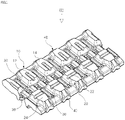
FIG. 1 is a perspective view showing a surface of a rubber track according to the present invention. -
FIG. 2 is a perspective view showing a back surface of the rubber track according to the present invention. -
FIG. 3 is a plan view showing a surface of the rubber track according to the present invention. - Hereinafter, the present invention will be described on the basis of exemplary embodiments illustrated in the drawings. As illustrated in
FIG. 1 showing the surface of the rubber track of the present invention, on a surface of a rubber track, afirst lug 10 and asecond lug 20 are arranged at the inside and the outside in a line, respectively. - In the present specification, the "
surface 2" refers to a surface of the rubber track coming into contact with the ground and the "back surface 4" refers to a surface which does not come into contact with the ground, that is, an opposite surface of thesurface 2. In addition, the "outside" of the rubber track refers to an outer portion in a pair of rubber tracks installed in a device and the "inside" is defined as meaning the inner portion which is close to the pair of rubber tracks. - In the
surface 2 of the rubber track of the present invention, a main lug formed to basically exhibit traction force may be thefirst lug 10 and thesecond lug 20. In addition, thefirst lug 10 and thesecond lug 20 have substantially different shapes. Thefirst lug 10 hasfirst grooves 12 formed in a width direction and thesecond lug 20 has asecond grooves 22 formed in a traveling direction. - As such, by forming the
first lug 10 and thesecond lug 20, which have different structures at the inside and the outside, respectively, the functions of therespective lugs first lug 10 is formed to have thefirst groove 12 in the width direction of the rubber track to secure basic traction force. In addition, when thefirst grooves 12 are formed in the width direction and bent in an arc form on the track, it is expected that the rubber track will be advantageous to be flexibly deformed to have a specific radius of curvature. In the present specification, it is assumed that the function has flexibility that the rubber track may be flexibly bent. - The
first lug 10 and thesecond lug 20 are asymmetrically rather than symmetrically formed as seen more clearly inFIG. 3 . Herein, it can be understood that the fact that thefirst lug 10 and thesecond lug 20 are asymmetrically formed means that thefirst lug 10 and thesecond lug 20 are alternately arranged based on anengaging portion 38 or alternately arranged in a traveling direction, as illustrated in the drawing. - In addition, it can be seen that the
first groove 12 of thefirst lug 10 is in a state where the outside is closed, that is, for example, thefirst lug 10 has a U shape because the outside is closed. As such, when thefirst groove 12 is formed so that the outside is closed, it may be natural that the surface area of thelug 10 may be substantially further secured. In addition, as such, through thefirst lug 10 having thefirst groove 12 with the closed outside, it is expected to provide stability in rotation or an inclined area of equipment (such as an excavator). - As described above, in the
second lug 20 formed at the other side of thefirst lug 10, thesecond grooves 22 are formed in the traveling direction. Herein, the inner and outer positions of thefirst lug 10 and thesecond lug 20 are selected, and for example, when thefirst lug 10 is formed at the inside of the rubber track, thesecond lug 20 is formed at the outside, and when thefirst lug 10 is formed at the outside the rubber track, thesecond lug 20 is formed at the inside. Since thesecond grooves 22 are formed in the traveling direction in thesecond lug 20, thesecond grooves 22 may be firmly supported against the centrifugal force during rotation and may be prevented from slipping from the slope to the side at the same time. - The reason why the
second lug 20 may prevent a side slip phenomenon that may occur in the slope is that thesecond grooves 22 are formed to have sufficient lengths in the traveling direction and formed in a state where the front and rear sides of thegroove 22 are opened. It should be understood that extraction performance is excellent and sufficient side support force may be secured at the same time by the structure of thesecond groove 22. - As described above, the
first lug 10 and thesecond lug 20 may be substantially the main lugs, and a size ofcontact surfaces main lugs auxiliary lugs 30 is formed between thefirst lug 10 and thesecond lug 20, respectively. Theseauxiliary lugs 30 are formed in the width direction and formed to be lower and smaller than thefirst lug 10 or thesecond lug 20 in height and size, but has the following functions. - The
auxiliary lugs 30 may perform a function of assisting the traction force in the soft ground. Although theauxiliary lug 30 is formed lower than thefirst lug 10 and thesecond lug 20 described above in height, theauxiliary lug 30 may have a function as an auxiliary means capable of exhibiting the traction force while the rubber track no longer falls out in the soft ground such as wetlands. - In addition, the
auxiliary lug 30 is substantially formed at a concave portion between thefirst lug 10 and thesecond lug 20. In addition, like themain lugs portion 38, which receive a sprocket from the rubber track and transmit the power to the rubber track. Theauxiliary lug 30 also has a function of preventing the steel cord embedded in the rubber track from being exposed between themain lugs - Further, the
auxiliary lug 30 is formed to extend inward and outward based on the engagingportion 38, and theauxiliary lug 30 may substantially have a function of connecting the central portion and the outer portion of the rubber track. As a result, theauxiliary lug 30 may help to prevent the occurrence of an edge-cut that may occur at the edge portion of the rubber track as much as possible. - In addition, according to the present invention, a
side protrusion 40 is formed to surround the side surfaces of thefirst lug 10 and thesecond lug 20. The side protrusion 40 passes through the side surfaces from thesurface 2 of thefirst lug 10 and thesecond lug 20 and then extends to theback surface 4 of the rubber track as illustrated inFIG. 2 . Accordingly, it can be seen that theside protrusion 40 is formed by surrounding thesurface 2 and theback surface 4 of the rubber track, and by such a configuration, substantially, it possible to prevent the occurrence of the edge-cut that may occur at the outside of the end portion of ametal core 36. - Such as
side protrusion 40 has also a function of exhibiting sufficient traction force in the soft ground. That is, when the rubber track somewhat falls out of the soft ground, theside protrusion 40 located on the side of the rubber track may exhibit traction force for traveling, and it may refer to a function based on the structure which substantially protrudes while surrounding the entire side surface of the rubber track. - Referring to
FIG. 2 , as described above, it can be seen that theside protrusion 40 protrudes while surrounding the entire side surface of the rubber track. In addition, in theback surface 4 of the rubber track, it can be seen that the end portion of theside protrusion 40 is bisected. As such, it is expected that stress concentration may be prevented by dispersing the load applied to theside protrusion 40 during traveling by forming the end of theback surface 4 of theside protrusion 40 which has a bisected fork shape. - In addition, on the
back surface 4 of the rubber track of the present invention, it can be seen that steppedportions 48 having continuous steps like stairs are formed on both sides. It can be seen that the stepped portions are formed so as to have an inclination toward the outer side. The inclined steppedportions 48 may be used to remove foreign materials that may be deposited by traveling to the outside, and may have a self-cleaning function in a sense. - By the traveling of the traveling device, the foreign materials are deposited on the
back surface 4 of the rubber track. Herein, when the rubber track is bent in an arc shape while entering the front or rear side of the rubber track, the foreign materials deposited inside the steppedportion 48 is subjected to predetermined external force due to deformation of the bent steppedportion 48, and such external force will act as force to drop the foreign materials from theback surface 4 of the rubber track to the outside. - Due to the structure of the stepped
portion 48 itself and the inclined structure, the foreign materials deposited in the stepped portion is different in thickness. The foreign materials deposited in such different thickness may be more easily detached by the external force received in the process in which the steppedportion 48 of the rubber track is bent in the arc shape. Herein, it is natural that the end of theside protrusion 40 bisected in the fork shape while extending to theback surface 4 of the rubber track may apply the external force to the foreign materials so that the foreign materials may be easily detached in cooperation with the steppedportion 40 in the process of bending the rubber track. - It is expected that a structure in which mountains and valleys are repeated instead of the structure of the stepped
portion 48 may have the same function and action effect. In addition, even in such a case, it is preferable to form the rubber track so as to have a somewhat reduced thickness toward both side edges of the rubber track. - It will be apparent to those skilled in the art that various modifications are possible within the technical scope of the present invention as described above. In addition, the scope of the present invention should be interpreted based on the scope of the appended claims.
Claims (4)
- A rubber track, comprising:first lugs (10) formed at equal intervals on one side of the inside or the outside in a traveling direction on a surface (2) of the rubber track coming into contact with the ground and having first grooves (12) formed in a width direction,characterized by further comprising: second lugs (20) formed at equal intervals on the other side of the inside or the outside in a traveling direction on the surface coming into contact with the ground and having second grooves (22) formed in the traveling direction, andan inclined stepped portion (48) formed at both sides of a back surface (4) of the rubber track to be inclined outward,wherein the rubber track is deformable to have a certain radius of curvature,wherein the inclined stepped portion (48) applies external force to foreign substances to be separated from the back surface (4) of the rubber track when the rubber track is bent.
- The rubber track of claim 1, wherein side protrusions (40) formed to protrude from the surface to the back surface (4) through the sides of the first and second lugs (10, 20) are provided on an outside of the first and second lugs (10, 20).
- The rubber track of claim 2, wherein the side protrusions (40) extend on the back surface of the rubber track in the width direction, and the end portion of the side protrusions (40) are bisected.
- The rubber track of claim 3, wherein the bisected end of the side protrusion (40) is adapted to cooperate with the inclined stepped portions (48) during bending of the track to aid in the detachment of any foreign material .
Applications Claiming Priority (2)
| Application Number | Priority Date | Filing Date | Title |
|---|---|---|---|
| KR1020150101165A KR101788659B1 (en) | 2015-07-16 | 2015-07-16 | Rubber Track |
| PCT/KR2016/007471 WO2017010756A1 (en) | 2015-07-16 | 2016-07-11 | Rubber track |
Publications (3)
| Publication Number | Publication Date |
|---|---|
| EP3323700A1 EP3323700A1 (en) | 2018-05-23 |
| EP3323700A4 EP3323700A4 (en) | 2018-07-25 |
| EP3323700B1 true EP3323700B1 (en) | 2022-12-07 |
Family
ID=57757868
Family Applications (1)
| Application Number | Title | Priority Date | Filing Date |
|---|---|---|---|
| EP16824673.4A Active EP3323700B1 (en) | 2015-07-16 | 2016-07-11 | Rubber track |
Country Status (6)
| Country | Link |
|---|---|
| US (1) | US11001318B2 (en) |
| EP (1) | EP3323700B1 (en) |
| JP (1) | JP6517999B2 (en) |
| KR (1) | KR101788659B1 (en) |
| CN (1) | CN107750220B (en) |
| WO (1) | WO2017010756A1 (en) |
Cited By (1)
| Publication number | Priority date | Publication date | Assignee | Title |
|---|---|---|---|---|
| US12049268B2 (en) | 2020-05-12 | 2024-07-30 | Yong Jae Choi | Elastic crawler |
Families Citing this family (10)
| Publication number | Priority date | Publication date | Assignee | Title |
|---|---|---|---|---|
| RU2673168C2 (en) * | 2017-01-31 | 2018-11-22 | Акционерное общество "Центральный научно-исследовательский институт специального машиностроения" (АО "ЦНИИСМ") | Infinite elastic track of vehicle |
| US11970226B2 (en) * | 2019-11-18 | 2024-04-30 | Yong Jae Choi | Elastic crawler |
| USD976157S1 (en) * | 2020-02-07 | 2023-01-24 | Drb Industrial Co., Ltd | Metal core for rubber track |
| CN112660259B (en) * | 2020-11-17 | 2023-03-03 | 崔镕宰 | Elastic crawler belt |
| US12539927B2 (en) * | 2021-05-11 | 2026-02-03 | Polaris Industries Inc. | Snow track for a snowmobile |
| USD996472S1 (en) * | 2021-10-12 | 2023-08-22 | Drb Industrial Co., Ltd. | Rubber track |
| CA3265001A1 (en) * | 2022-10-12 | 2024-04-18 | Camso Inc. | Uneven-edged track for traction of a vehicle |
| CN117508390A (en) * | 2023-11-13 | 2024-02-06 | 镇江同立橡胶有限公司 | An improved rubber track |
| CN221627775U (en) * | 2024-01-05 | 2024-08-30 | 元鼎智能创新(国际)有限公司 | Crawler belt and cleaning robot |
| JP7754972B2 (en) * | 2024-03-19 | 2025-10-15 | ゼニス産業株式会社 | Elastic Crawler |
Family Cites Families (26)
| Publication number | Priority date | Publication date | Assignee | Title |
|---|---|---|---|---|
| CA432667A (en) * | 1943-02-03 | 1946-01-22 | L. Haushalter Fred | Vehicle track |
| US3387897A (en) * | 1964-04-14 | 1968-06-11 | Int Paper Canada | Track shoe |
| US3815817A (en) * | 1973-05-11 | 1974-06-11 | Flextrac Nodwell Ltd | Tundra track for a tracked vehicle |
| EP0078635B1 (en) * | 1981-10-31 | 1987-02-25 | George Blair P.L.C. | Track tread |
| JPH01229782A (en) * | 1988-03-10 | 1989-09-13 | Ohtsu Tire & Rubber Co Ltd :The | Elastic crawler belt |
| JP3636785B2 (en) * | 1995-08-29 | 2005-04-06 | 株式会社ブリヂストン | Ladder type crawler |
| WO1998007613A1 (en) * | 1996-08-20 | 1998-02-26 | Yanmar Diesel Engine Co., Ltd. | Swivel working vehicle |
| EP1008509B1 (en) * | 1997-09-05 | 2005-11-23 | Komatsu Ltd | Elastic flat tread |
| US6505896B1 (en) | 2000-09-01 | 2003-01-14 | Alain Boivin | Track for snow vehicles |
| US6267453B1 (en) * | 1999-11-12 | 2001-07-31 | Soucy International Inc. | Endless track with debris evacuation side outlets |
| JP2001322576A (en) * | 2000-03-09 | 2001-11-20 | Bridgestone Corp | Rubber crawler |
| US6520603B2 (en) * | 2001-03-15 | 2003-02-18 | Takeuchi Mfg, Co., Ltd. | Low-noise endless crawler belt having embedded core bars and detachable crawler shoes |
| SG130936A1 (en) | 2001-09-11 | 2007-04-26 | Soucy Int Inc | Endless track for high speed multi-terrain vehicles |
| JP3673748B2 (en) * | 2001-11-02 | 2005-07-20 | 住友ゴム工業株式会社 | Elastic crawler |
| EP1564120B1 (en) * | 2002-11-20 | 2009-09-16 | Bridgestone Corporation | Rubber track |
| JP3883129B2 (en) * | 2004-03-22 | 2007-02-21 | 住友ゴム工業株式会社 | Ladder-type crawler |
| JP4549138B2 (en) * | 2004-09-03 | 2010-09-22 | 住友ゴム工業株式会社 | Elastic crawler |
| KR100693270B1 (en) * | 2005-07-19 | 2007-03-13 | 대륙화학공업 주식회사 | Crawler Lug Pattern Structure |
| CA2628201C (en) * | 2008-04-02 | 2013-12-03 | Soucy International Inc. | Endless track |
| JP5349017B2 (en) * | 2008-11-20 | 2013-11-20 | 住友ゴム工業株式会社 | Elastic track |
| US7866767B2 (en) | 2008-12-11 | 2011-01-11 | Soucy International Inc. | Traction band |
| US8888198B2 (en) * | 2009-04-22 | 2014-11-18 | Bridgestone Corporation | Rubber crawler |
| JP5411627B2 (en) * | 2009-08-27 | 2014-02-12 | 株式会社ブリヂストン | Rubber crawler |
| WO2012039431A1 (en) * | 2010-09-21 | 2012-03-29 | 株式会社ブリヂストン | Elastic crawler |
| CN103347775B (en) * | 2010-11-25 | 2016-01-20 | 株式会社普利司通 | rubber track |
| JP5577419B1 (en) * | 2013-02-25 | 2014-08-20 | 株式会社ブリヂストン | Crawler |
-
2015
- 2015-07-16 KR KR1020150101165A patent/KR101788659B1/en active Active
-
2016
- 2016-07-11 EP EP16824673.4A patent/EP3323700B1/en active Active
- 2016-07-11 US US15/743,344 patent/US11001318B2/en active Active
- 2016-07-11 CN CN201680035939.9A patent/CN107750220B/en active Active
- 2016-07-11 JP JP2018500623A patent/JP6517999B2/en active Active
- 2016-07-11 WO PCT/KR2016/007471 patent/WO2017010756A1/en not_active Ceased
Cited By (1)
| Publication number | Priority date | Publication date | Assignee | Title |
|---|---|---|---|---|
| US12049268B2 (en) | 2020-05-12 | 2024-07-30 | Yong Jae Choi | Elastic crawler |
Also Published As
| Publication number | Publication date |
|---|---|
| US11001318B2 (en) | 2021-05-11 |
| CN107750220A (en) | 2018-03-02 |
| KR20170009325A (en) | 2017-01-25 |
| KR101788659B1 (en) | 2017-11-15 |
| EP3323700A1 (en) | 2018-05-23 |
| JP2018524232A (en) | 2018-08-30 |
| JP6517999B2 (en) | 2019-05-22 |
| EP3323700A4 (en) | 2018-07-25 |
| US20180201335A1 (en) | 2018-07-19 |
| CN107750220B (en) | 2020-06-02 |
| WO2017010756A1 (en) | 2017-01-19 |
Similar Documents
| Publication | Publication Date | Title |
|---|---|---|
| US11001318B2 (en) | Rubber track | |
| US5522655A (en) | Rubber crawler | |
| EP0895924B1 (en) | Rubber crawler track | |
| EP1386831A1 (en) | Elastic endless crawler | |
| JP5411627B2 (en) | Rubber crawler | |
| US10435091B2 (en) | Elastic crawler and elastic crawler device | |
| JP6359977B2 (en) | Pneumatic tires for vehicles | |
| EP3133000B1 (en) | Endless track | |
| CN106852135A (en) | The tire tread of the variable thickness tread groove in region including reducing with multiple thickness | |
| JP5933783B2 (en) | Rubber crawler | |
| CN106142998A (en) | A kind of tire | |
| US20150210128A1 (en) | Snow chain for vehicles | |
| JP6934810B2 (en) | Rubber crawler | |
| JP5382762B2 (en) | Elastic crawler | |
| US10435090B2 (en) | Elastic crawler | |
| WO2019097834A1 (en) | Rubber crawler-track pad | |
| JP4471456B2 (en) | Elastic crawler and core body for elastic crawler | |
| JP5587574B2 (en) | Rubber crawler | |
| EP3132999B1 (en) | Crawler | |
| JP2007131032A (en) | Rubber crawler | |
| JP6438229B2 (en) | Rubber crawler | |
| JPS5851668Y2 (en) | rubber crawler | |
| JPH0623514Y2 (en) | Crawler | |
| JPH08224Y2 (en) | Rubber crawler for wetlands | |
| JP4719503B2 (en) | Elastic crawler |
Legal Events
| Date | Code | Title | Description |
|---|---|---|---|
| STAA | Information on the status of an ep patent application or granted ep patent |
Free format text: STATUS: THE INTERNATIONAL PUBLICATION HAS BEEN MADE |
|
| PUAI | Public reference made under article 153(3) epc to a published international application that has entered the european phase |
Free format text: ORIGINAL CODE: 0009012 |
|
| STAA | Information on the status of an ep patent application or granted ep patent |
Free format text: STATUS: REQUEST FOR EXAMINATION WAS MADE |
|
| 17P | Request for examination filed |
Effective date: 20180205 |
|
| AK | Designated contracting states |
Kind code of ref document: A1 Designated state(s): AL AT BE BG CH CY CZ DE DK EE ES FI FR GB GR HR HU IE IS IT LI LT LU LV MC MK MT NL NO PL PT RO RS SE SI SK SM TR |
|
| AX | Request for extension of the european patent |
Extension state: BA ME |
|
| A4 | Supplementary search report drawn up and despatched |
Effective date: 20180622 |
|
| RIC1 | Information provided on ipc code assigned before grant |
Ipc: B62D 55/26 20060101ALI20180618BHEP Ipc: B62D 55/24 20060101AFI20180618BHEP |
|
| DAV | Request for validation of the european patent (deleted) | ||
| DAX | Request for extension of the european patent (deleted) | ||
| STAA | Information on the status of an ep patent application or granted ep patent |
Free format text: STATUS: EXAMINATION IS IN PROGRESS |
|
| 17Q | First examination report despatched |
Effective date: 20200514 |
|
| GRAP | Despatch of communication of intention to grant a patent |
Free format text: ORIGINAL CODE: EPIDOSNIGR1 |
|
| STAA | Information on the status of an ep patent application or granted ep patent |
Free format text: STATUS: GRANT OF PATENT IS INTENDED |
|
| INTG | Intention to grant announced |
Effective date: 20220804 |
|
| GRAS | Grant fee paid |
Free format text: ORIGINAL CODE: EPIDOSNIGR3 |
|
| GRAA | (expected) grant |
Free format text: ORIGINAL CODE: 0009210 |
|
| STAA | Information on the status of an ep patent application or granted ep patent |
Free format text: STATUS: THE PATENT HAS BEEN GRANTED |
|
| AK | Designated contracting states |
Kind code of ref document: B1 Designated state(s): AL AT BE BG CH CY CZ DE DK EE ES FI FR GB GR HR HU IE IS IT LI LT LU LV MC MK MT NL NO PL PT RO RS SE SI SK SM TR |
|
| REG | Reference to a national code |
Ref country code: GB Ref legal event code: FG4D |
|
| REG | Reference to a national code |
Ref country code: CH Ref legal event code: EP Ref country code: AT Ref legal event code: REF Ref document number: 1536157 Country of ref document: AT Kind code of ref document: T Effective date: 20221215 |
|
| REG | Reference to a national code |
Ref country code: DE Ref legal event code: R096 Ref document number: 602016076801 Country of ref document: DE |
|
| REG | Reference to a national code |
Ref country code: IE Ref legal event code: FG4D |
|
| REG | Reference to a national code |
Ref country code: LT Ref legal event code: MG9D |
|
| REG | Reference to a national code |
Ref country code: NL Ref legal event code: MP Effective date: 20221207 |
|
| PG25 | Lapsed in a contracting state [announced via postgrant information from national office to epo] |
Ref country code: SE Free format text: LAPSE BECAUSE OF FAILURE TO SUBMIT A TRANSLATION OF THE DESCRIPTION OR TO PAY THE FEE WITHIN THE PRESCRIBED TIME-LIMIT Effective date: 20221207 Ref country code: NO Free format text: LAPSE BECAUSE OF FAILURE TO SUBMIT A TRANSLATION OF THE DESCRIPTION OR TO PAY THE FEE WITHIN THE PRESCRIBED TIME-LIMIT Effective date: 20230307 Ref country code: LT Free format text: LAPSE BECAUSE OF FAILURE TO SUBMIT A TRANSLATION OF THE DESCRIPTION OR TO PAY THE FEE WITHIN THE PRESCRIBED TIME-LIMIT Effective date: 20221207 Ref country code: FI Free format text: LAPSE BECAUSE OF FAILURE TO SUBMIT A TRANSLATION OF THE DESCRIPTION OR TO PAY THE FEE WITHIN THE PRESCRIBED TIME-LIMIT Effective date: 20221207 Ref country code: ES Free format text: LAPSE BECAUSE OF FAILURE TO SUBMIT A TRANSLATION OF THE DESCRIPTION OR TO PAY THE FEE WITHIN THE PRESCRIBED TIME-LIMIT Effective date: 20221207 |
|
| REG | Reference to a national code |
Ref country code: AT Ref legal event code: MK05 Ref document number: 1536157 Country of ref document: AT Kind code of ref document: T Effective date: 20221207 |
|
| PG25 | Lapsed in a contracting state [announced via postgrant information from national office to epo] |
Ref country code: RS Free format text: LAPSE BECAUSE OF FAILURE TO SUBMIT A TRANSLATION OF THE DESCRIPTION OR TO PAY THE FEE WITHIN THE PRESCRIBED TIME-LIMIT Effective date: 20221207 Ref country code: PL Free format text: LAPSE BECAUSE OF FAILURE TO SUBMIT A TRANSLATION OF THE DESCRIPTION OR TO PAY THE FEE WITHIN THE PRESCRIBED TIME-LIMIT Effective date: 20221207 Ref country code: LV Free format text: LAPSE BECAUSE OF FAILURE TO SUBMIT A TRANSLATION OF THE DESCRIPTION OR TO PAY THE FEE WITHIN THE PRESCRIBED TIME-LIMIT Effective date: 20221207 Ref country code: HR Free format text: LAPSE BECAUSE OF FAILURE TO SUBMIT A TRANSLATION OF THE DESCRIPTION OR TO PAY THE FEE WITHIN THE PRESCRIBED TIME-LIMIT Effective date: 20221207 Ref country code: GR Free format text: LAPSE BECAUSE OF FAILURE TO SUBMIT A TRANSLATION OF THE DESCRIPTION OR TO PAY THE FEE WITHIN THE PRESCRIBED TIME-LIMIT Effective date: 20230308 |
|
| PG25 | Lapsed in a contracting state [announced via postgrant information from national office to epo] |
Ref country code: NL Free format text: LAPSE BECAUSE OF FAILURE TO SUBMIT A TRANSLATION OF THE DESCRIPTION OR TO PAY THE FEE WITHIN THE PRESCRIBED TIME-LIMIT Effective date: 20221207 |
|
| PG25 | Lapsed in a contracting state [announced via postgrant information from national office to epo] |
Ref country code: SM Free format text: LAPSE BECAUSE OF FAILURE TO SUBMIT A TRANSLATION OF THE DESCRIPTION OR TO PAY THE FEE WITHIN THE PRESCRIBED TIME-LIMIT Effective date: 20221207 Ref country code: RO Free format text: LAPSE BECAUSE OF FAILURE TO SUBMIT A TRANSLATION OF THE DESCRIPTION OR TO PAY THE FEE WITHIN THE PRESCRIBED TIME-LIMIT Effective date: 20221207 Ref country code: PT Free format text: LAPSE BECAUSE OF FAILURE TO SUBMIT A TRANSLATION OF THE DESCRIPTION OR TO PAY THE FEE WITHIN THE PRESCRIBED TIME-LIMIT Effective date: 20230410 Ref country code: EE Free format text: LAPSE BECAUSE OF FAILURE TO SUBMIT A TRANSLATION OF THE DESCRIPTION OR TO PAY THE FEE WITHIN THE PRESCRIBED TIME-LIMIT Effective date: 20221207 Ref country code: CZ Free format text: LAPSE BECAUSE OF FAILURE TO SUBMIT A TRANSLATION OF THE DESCRIPTION OR TO PAY THE FEE WITHIN THE PRESCRIBED TIME-LIMIT Effective date: 20221207 Ref country code: AT Free format text: LAPSE BECAUSE OF FAILURE TO SUBMIT A TRANSLATION OF THE DESCRIPTION OR TO PAY THE FEE WITHIN THE PRESCRIBED TIME-LIMIT Effective date: 20221207 |
|
| PG25 | Lapsed in a contracting state [announced via postgrant information from national office to epo] |
Ref country code: SK Free format text: LAPSE BECAUSE OF FAILURE TO SUBMIT A TRANSLATION OF THE DESCRIPTION OR TO PAY THE FEE WITHIN THE PRESCRIBED TIME-LIMIT Effective date: 20221207 Ref country code: IS Free format text: LAPSE BECAUSE OF FAILURE TO SUBMIT A TRANSLATION OF THE DESCRIPTION OR TO PAY THE FEE WITHIN THE PRESCRIBED TIME-LIMIT Effective date: 20230407 Ref country code: AL Free format text: LAPSE BECAUSE OF FAILURE TO SUBMIT A TRANSLATION OF THE DESCRIPTION OR TO PAY THE FEE WITHIN THE PRESCRIBED TIME-LIMIT Effective date: 20221207 |
|
| REG | Reference to a national code |
Ref country code: DE Ref legal event code: R097 Ref document number: 602016076801 Country of ref document: DE |
|
| PLBE | No opposition filed within time limit |
Free format text: ORIGINAL CODE: 0009261 |
|
| STAA | Information on the status of an ep patent application or granted ep patent |
Free format text: STATUS: NO OPPOSITION FILED WITHIN TIME LIMIT |
|
| PG25 | Lapsed in a contracting state [announced via postgrant information from national office to epo] |
Ref country code: DK Free format text: LAPSE BECAUSE OF FAILURE TO SUBMIT A TRANSLATION OF THE DESCRIPTION OR TO PAY THE FEE WITHIN THE PRESCRIBED TIME-LIMIT Effective date: 20221207 |
|
| 26N | No opposition filed |
Effective date: 20230908 |
|
| PG25 | Lapsed in a contracting state [announced via postgrant information from national office to epo] |
Ref country code: SI Free format text: LAPSE BECAUSE OF FAILURE TO SUBMIT A TRANSLATION OF THE DESCRIPTION OR TO PAY THE FEE WITHIN THE PRESCRIBED TIME-LIMIT Effective date: 20221207 |
|
| PG25 | Lapsed in a contracting state [announced via postgrant information from national office to epo] |
Ref country code: MC Free format text: LAPSE BECAUSE OF FAILURE TO SUBMIT A TRANSLATION OF THE DESCRIPTION OR TO PAY THE FEE WITHIN THE PRESCRIBED TIME-LIMIT Effective date: 20221207 |
|
| PG25 | Lapsed in a contracting state [announced via postgrant information from national office to epo] |
Ref country code: MC Free format text: LAPSE BECAUSE OF FAILURE TO SUBMIT A TRANSLATION OF THE DESCRIPTION OR TO PAY THE FEE WITHIN THE PRESCRIBED TIME-LIMIT Effective date: 20221207 |
|
| REG | Reference to a national code |
Ref country code: CH Ref legal event code: PL |
|
| REG | Reference to a national code |
Ref country code: BE Ref legal event code: MM Effective date: 20230731 |
|
| PG25 | Lapsed in a contracting state [announced via postgrant information from national office to epo] |
Ref country code: LU Free format text: LAPSE BECAUSE OF NON-PAYMENT OF DUE FEES Effective date: 20230711 |
|
| PG25 | Lapsed in a contracting state [announced via postgrant information from national office to epo] |
Ref country code: LU Free format text: LAPSE BECAUSE OF NON-PAYMENT OF DUE FEES Effective date: 20230711 |
|
| REG | Reference to a national code |
Ref country code: IE Ref legal event code: MM4A |
|
| PG25 | Lapsed in a contracting state [announced via postgrant information from national office to epo] |
Ref country code: CH Free format text: LAPSE BECAUSE OF NON-PAYMENT OF DUE FEES Effective date: 20230731 |
|
| PG25 | Lapsed in a contracting state [announced via postgrant information from national office to epo] |
Ref country code: BE Free format text: LAPSE BECAUSE OF NON-PAYMENT OF DUE FEES Effective date: 20230731 |
|
| PG25 | Lapsed in a contracting state [announced via postgrant information from national office to epo] |
Ref country code: IE Free format text: LAPSE BECAUSE OF NON-PAYMENT OF DUE FEES Effective date: 20230711 |
|
| PG25 | Lapsed in a contracting state [announced via postgrant information from national office to epo] |
Ref country code: IE Free format text: LAPSE BECAUSE OF NON-PAYMENT OF DUE FEES Effective date: 20230711 |
|
| PG25 | Lapsed in a contracting state [announced via postgrant information from national office to epo] |
Ref country code: BG Free format text: LAPSE BECAUSE OF FAILURE TO SUBMIT A TRANSLATION OF THE DESCRIPTION OR TO PAY THE FEE WITHIN THE PRESCRIBED TIME-LIMIT Effective date: 20221207 |
|
| PG25 | Lapsed in a contracting state [announced via postgrant information from national office to epo] |
Ref country code: BG Free format text: LAPSE BECAUSE OF FAILURE TO SUBMIT A TRANSLATION OF THE DESCRIPTION OR TO PAY THE FEE WITHIN THE PRESCRIBED TIME-LIMIT Effective date: 20221207 |
|
| PGFP | Annual fee paid to national office [announced via postgrant information from national office to epo] |
Ref country code: GB Payment date: 20250619 Year of fee payment: 10 |
|
| PGFP | Annual fee paid to national office [announced via postgrant information from national office to epo] |
Ref country code: FR Payment date: 20250619 Year of fee payment: 10 |
|
| PG25 | Lapsed in a contracting state [announced via postgrant information from national office to epo] |
Ref country code: CY Free format text: LAPSE BECAUSE OF FAILURE TO SUBMIT A TRANSLATION OF THE DESCRIPTION OR TO PAY THE FEE WITHIN THE PRESCRIBED TIME-LIMIT; INVALID AB INITIO Effective date: 20160711 |
|
| PG25 | Lapsed in a contracting state [announced via postgrant information from national office to epo] |
Ref country code: HU Free format text: LAPSE BECAUSE OF FAILURE TO SUBMIT A TRANSLATION OF THE DESCRIPTION OR TO PAY THE FEE WITHIN THE PRESCRIBED TIME-LIMIT; INVALID AB INITIO Effective date: 20160711 |
|
| PGFP | Annual fee paid to national office [announced via postgrant information from national office to epo] |
Ref country code: DE Payment date: 20250620 Year of fee payment: 10 |
|
| PGFP | Annual fee paid to national office [announced via postgrant information from national office to epo] |
Ref country code: IT Payment date: 20250619 Year of fee payment: 10 |
|
| PG25 | Lapsed in a contracting state [announced via postgrant information from national office to epo] |
Ref country code: TR Free format text: LAPSE BECAUSE OF FAILURE TO SUBMIT A TRANSLATION OF THE DESCRIPTION OR TO PAY THE FEE WITHIN THE PRESCRIBED TIME-LIMIT Effective date: 20221207 |