EP3323644A1 - Apparatus for mounting and removing a tyre - Google Patents
Apparatus for mounting and removing a tyre Download PDFInfo
- Publication number
- EP3323644A1 EP3323644A1 EP17199669.7A EP17199669A EP3323644A1 EP 3323644 A1 EP3323644 A1 EP 3323644A1 EP 17199669 A EP17199669 A EP 17199669A EP 3323644 A1 EP3323644 A1 EP 3323644A1
- Authority
- EP
- European Patent Office
- Prior art keywords
- tool
- wheel
- floorplate
- holder
- axis
- Prior art date
- Legal status (The legal status is an assumption and is not a legal conclusion. Google has not performed a legal analysis and makes no representation as to the accuracy of the status listed.)
- Granted
Links
Images



Classifications
-
- B—PERFORMING OPERATIONS; TRANSPORTING
- B60—VEHICLES IN GENERAL
- B60C—VEHICLE TYRES; TYRE INFLATION; TYRE CHANGING; CONNECTING VALVES TO INFLATABLE ELASTIC BODIES IN GENERAL; DEVICES OR ARRANGEMENTS RELATED TO TYRES
- B60C25/00—Apparatus or tools adapted for mounting, removing or inspecting tyres
- B60C25/01—Apparatus or tools adapted for mounting, removing or inspecting tyres for removing tyres from or mounting tyres on wheels
- B60C25/05—Machines
- B60C25/132—Machines for removing and mounting tyres
- B60C25/135—Machines for removing and mounting tyres having a tyre support or a tool, movable along wheel axis
- B60C25/138—Machines for removing and mounting tyres having a tyre support or a tool, movable along wheel axis with rotary motion of tool or tyre support
-
- B—PERFORMING OPERATIONS; TRANSPORTING
- B60—VEHICLES IN GENERAL
- B60C—VEHICLE TYRES; TYRE INFLATION; TYRE CHANGING; CONNECTING VALVES TO INFLATABLE ELASTIC BODIES IN GENERAL; DEVICES OR ARRANGEMENTS RELATED TO TYRES
- B60C25/00—Apparatus or tools adapted for mounting, removing or inspecting tyres
- B60C25/01—Apparatus or tools adapted for mounting, removing or inspecting tyres for removing tyres from or mounting tyres on wheels
- B60C25/05—Machines
- B60C25/0515—Automated devices, e.g. mounting robots
-
- B—PERFORMING OPERATIONS; TRANSPORTING
- B60—VEHICLES IN GENERAL
- B60C—VEHICLE TYRES; TYRE INFLATION; TYRE CHANGING; CONNECTING VALVES TO INFLATABLE ELASTIC BODIES IN GENERAL; DEVICES OR ARRANGEMENTS RELATED TO TYRES
- B60C25/00—Apparatus or tools adapted for mounting, removing or inspecting tyres
- B60C25/01—Apparatus or tools adapted for mounting, removing or inspecting tyres for removing tyres from or mounting tyres on wheels
- B60C25/05—Machines
- B60C25/0518—Horizontal wheel axis in working position
-
- B—PERFORMING OPERATIONS; TRANSPORTING
- B60—VEHICLES IN GENERAL
- B60C—VEHICLE TYRES; TYRE INFLATION; TYRE CHANGING; CONNECTING VALVES TO INFLATABLE ELASTIC BODIES IN GENERAL; DEVICES OR ARRANGEMENTS RELATED TO TYRES
- B60C25/00—Apparatus or tools adapted for mounting, removing or inspecting tyres
- B60C25/01—Apparatus or tools adapted for mounting, removing or inspecting tyres for removing tyres from or mounting tyres on wheels
- B60C25/05—Machines
- B60C25/132—Machines for removing and mounting tyres
-
- B—PERFORMING OPERATIONS; TRANSPORTING
- B60—VEHICLES IN GENERAL
- B60C—VEHICLE TYRES; TYRE INFLATION; TYRE CHANGING; CONNECTING VALVES TO INFLATABLE ELASTIC BODIES IN GENERAL; DEVICES OR ARRANGEMENTS RELATED TO TYRES
- B60C25/00—Apparatus or tools adapted for mounting, removing or inspecting tyres
- B60C25/01—Apparatus or tools adapted for mounting, removing or inspecting tyres for removing tyres from or mounting tyres on wheels
- B60C25/05—Machines
- B60C25/0521—Handling of rim or tyre, e.g. lifting and positioning devices
Definitions
- This invention relates to an apparatus for mounting and removing a tyre.
- an apparatus for mounting and removing a tyre is also referred to by the term "tyre changing machine” to denote a machine configured to carry out at least part of the operations needed to remove a tyre from a rim of a vehicle wheel and/or the operations needed to mount the tyre to the rim.
- tyre changing machine a machine configured to carry out at least part of the operations needed to remove a tyre from a rim of a vehicle wheel and/or the operations needed to mount the tyre to the rim.
- Such machine is configured to carry out such at least part of the operations preferably at least partly automatically.
- one kind of tyre changing machine described for example in patent document EP2282898B1 comprises a support frame which mounts two slides.
- the first of these slides mounts a wheel-holder unit which the rim of a vehicle wheel, or the whole wheel - comprising the rim and the tyre mounted to the rim - can be locked to.
- the wheel-holder unit defines a locking axis which operatively coincides with the central axis of the rim or of the wheel when the rim of the wheel is locked in place on the wheel-holder unit.
- the wheel-holder unit is configured to rotate the rim or the wheel about an axis of rotation which operatively coincides with the locking axis.
- the second of these slides mounts a tool-holder turret, on which one or more tools may be fitted and which is configured to interact with the respective rim and/or with the respective tyre in order to perform, in conjunction with the wheel-holder unit, an operation on the wheel which may relate to mounting the tyre to the rim or to removing the tyre from the rim.
- the tool-holder turret may adopt one or more operating configurations, in each of which it directs at the wheel-holder unit a tool selected from the one or more tools in order to perform the required operation.
- the tool-holder turret keeps the selected tool at a respective operating position in such a way that the tool can perform, in conjunction with the wheel-holder unit, a respective operation relating to mounting or removing a vehicle wheel tyre to or from a rim, respectively.
- the machine comprises drive systems which operate on the slides to cause the wheel-holder unit and the tool-holder turret to be translated horizontally relative to each other in a horizontal direction parallel to the locking axis of the wheel-holder unit. Typically, this horizontal direction is at right angles to the force of gravity.
- These drive systems are also configured to cause the wheel-holder unit to be translated vertically relative to the tool-holder turret in a vertical direction transverse to the locking axis. Typically, this vertical direction is parallel to the force of gravity.
- the wheel-holder unit usually comprises at least one chuck, defining the locking axis, in order to lock the rim or wheel in place, and a motor drive system to set the chuck in rotation about the axis of rotation.
- the chuck and the motor drive system are quite cumbersome, in particular when they are configured to lock and set in rotation large rims or wheels.
- the wheel-holder unit Owing to the size of the wheel-holder unit and the presence of these drive systems, the wheel-holder unit must, in order to enable the selected tool to be positioned correctly relative to the rim and/or to the tyre, be kept at a certain working height from the floor, measured along the vertical direction parallel to gravity.
- the turret can keep the selected tool at a fixed working height which may be optimal only for wheels and/or tyres of a certain size but not for wheels and/or tyres of other sizes.
- the step of locking the rim or the entire wheel to the wheel-holder unit is carried out with the wheel-holder unit positioned at a height lower than the working height.
- the locking step may be performed with the help of floorplates which enable the operator to bring the rim or the wheel to a height such as to allow it to be locked to the wheel-holder unit but which is in any case always a height below the working height of the wheel-holder unit when the tool is in operation.
- Positioning the wheel-holder unit at the right working height requires adjustment of the height, which may take some time.
- the step of adjusting the position of the wheel-holder unit along the vertical direction must be repeated at every changeover from a specific operation carried out in the context of a wheel of one specific type to the same operation carried out in the context of another wheel of the same type.
- the adjustment must also be repeated when passing from removal to mounting, or vice versa, in the context of the same wheel.
- the aim of this description is to provide a tyre changing machine that overcomes the above mentioned disadvantages of the prior art.
- Another aim of this description is to provide a method for automatically carrying out at least one operation relating to the removal or mounting of a tyre respectively from and to a vehicle wheel rim to overcome the above mentioned disadvantages of the prior art.
- this description relates to a tyre changing machine for performing at least partly automatically operations relating to mounting or removing a vehicle wheel tyre to or from a rim, respectively.
- the machine is adapted and/or configured to be placed on a supporting surface.
- the machine comprises a bed configured and/or adapted to be placed on the supporting surface and/or to remain fixed relative to that supporting surface and on top of the supporting surface during operation of the tyre changing machine.
- the bed may be operatively fixed relative to the supporting surface but only rested on the supporting surface itself.
- the bed might also be operatively attached and/or coupled to the supporting surface.
- the bed is thus operatively fixed on the supporting surface.
- the bed comprises and/or defines a floorplate.
- the floorplate is preferably treadable and surmountable by a wheel and/or a tyre.
- the machine comprises a wheel-holder unit.
- wheel may denote either only the respective rim or the entire wheel, including the rim and the tyre mounted and/or at least partly or completely mounted to the rim.
- the wheel-holder unit defines a locking axis.
- the wheel-holder unit is configured to hold the wheel in a locked condition where the locking axis operatively coincides with a central axis of the wheel.
- the wheel-holder unit is configured to set the wheel, when operatively in the locked condition, in rotation about the locking axis.
- the machine includes a tool-holder turret which mounts at least one tool adapted to interact with the tyre (for example, a removal tool, a mounting tool or a bead breaker tool).
- the turret is movably connected to the bed.
- the machine comprises at least one tool-holder arm which mounts a further tool (for example, a removal tool, a mounting tool or a bead breaker tool).
- a further tool for example, a removal tool, a mounting tool or a bead breaker tool.
- the machine is configured in such a way that the tool-holder arm can be connected or fixed, preferably in removable manner, to the bed or to the floorplate.
- the machine comprises a drive system configured to cause movement of the wheel-holder unit relative to the supporting surface and/or relative to the bed and/or relative to the floorplate and/or relative to the tool-holder arm which is operatively connected to the bed or to the floorplate.
- the drive system is configured in such a way that this movement can comprise at least one longitudinal translational component.
- the longitudinal translational component is parallel to the locking axis or even directed along the locking axis.
- the longitudinal translational component is preferably operatively transverse, or even at right angles, to gravity, in which case it may be considered as a "horizontal" translational component.
- the drive system is configured in such a way that this movement can comprise at least a first transverse translational component.
- the first transverse translational component is transverse to the locking axis or even at right angles to the locking axis.
- the first transverse translational component is preferably operatively parallel to gravity, in which case it may be considered as a "vertical" translational component.
- the drive system is configured in such a way that this movement can comprise at least a second transverse translational component.
- the second transverse translational component is transverse to the locking axis or even at right angles to the locking axis.
- the second transverse translational component is preferably operatively transverse, or even at right angles, to gravity, in which case it may be considered as a "lateral" translational component.
- the drive system is configured to generate a movement of the wheel-holder unit comprising only one of the aforementioned translational components or a movement resulting from a simultaneous combination of one or more of these translational components.
- the movement system may cause the wheel-holder unit to perform a movement which simultaneously comprises the first transverse component and the second transverse component.
- the tool-holder arm is configured to hold the further tool in a position of mounting the further tool on the arm.
- This mounting position corresponds to an operating work position of the further tool where the same further tool, in conjunction with the wheel-holder unit, can perform at least one of the operations relating to the mounting or removal of the wheel tyre to and from the rim, respectively.
- the tool-holder arm is configured in such a way that when the further tool is held in its operating position by such arm, such further tool is also fixed or locked to the tool-holder arm itself.
- the bed is configured to keep the arm in a position of fixing the arm on the bed itself when the arm is connected to the bed or to the floorplate.
- This fixing position operatively corresponds to the operating position of the further tool. That means that when the arm is in the fixing position on the bed and the further tool is in the mounting position on the arm, the further tool is in the operating work position and is kept fixed in that operating work position relative to the bed and by means of the arm which is in turn fixed to the bed.
- the further tool may also be built directly into the arm, and thus be a part thereof, in which case it is in that mounting position.
- the tool-holder arm preferably has a first and a second end.
- the first end is operatively connected to the further tool; the other end is operatively connected directly to the bed or to the bed floorplate.
- the machine may comprise a plurality of tool-holder arms and a plurality of further tools (for example, removal tools, mounting tools or bead breaker tools). Each respective arm is configured to mount a respective further tool.
- each respective arm can be connected or fixed, preferably in removable manner, to the bed or to the floorplate.
- Each respective tool-holder arm is configured to mount the respective further tool and to hold it in a respective position of mounting the respective further tool on the respective arm.
- This mounting position corresponds to an operating work position of the respective further tool where the same respective further tool, in conjunction with the wheel-holder unit, can perform at least one of the operations relating to the mounting or removal of the wheel tyre to and from the rim, respectively.
- the bed is configured to keep the respective arms in respective positions of fixing the respective arms on the bed itself when such arms are connected to the bed or to the floorplate.
- These fixing positions operatively correspond to the respective operating positions of the respective further tools. That way, when the respective arms are in the respective fixing positions on the bed and the respective further tools are in the respective mounting positions on the respective arms, the respective further tools are in such respective operating positions and are kept fixed in such respective operating positions relative to the bed and by means of the respective arms which are in turn fixed to the bed.
- each respective further tool may also be built directly into the respective arm, and thus be a part thereof, in which case it may be said that it is always in that respective mounting position.
- this description relates to a method for performing at least one operation relating to mounting or removing a vehicle wheel tyre to or from a respective wheel rim, respectively.
- the method comprises a step of locking at least one wheel on a wheel-holder unit in such a way that a central axis of the wheel coincides with a locking axis defined by the wheel-holder unit.
- the method comprises a step of placing a bed on a supporting surface. This placement step is such that after it is performed, the bed remains fixed relative to the supporting surface.
- the placement step may comprise even only resting the bed on the supporting surface and/or it may comprise attaching the bed to the supporting surface.
- the method comprises a step of fixing a tool-holder arm fitted with a further tool in a position of fixing the arm on the bed.
- This step of fixing the tool-holder arm on the bed is carried out in such a way that the further tool adopts an operating work position to perform the at least one operation in conjunction with the wheel-holder unit.
- the method comprises a step of driving the wheel-holder unit relative to the supporting surface.
- This driving step may be carried out by generating at least one component of horizontal translational movement in a horizontal direction parallel to the locking axis.
- This driving step may be carried out by generating at least one component of vertical translational movement in a vertical direction transverse to the locking axis.
- the method comprises a step of performing the at least one operation by joint action between the (further) tool in the operating position and the wheel-holder unit.
- the fixing step includes fixing a plurality of tool-holder arms fitted with respective further tools in respective fixing positions on the bed. This step of fixing the tool-holder arms is carried out in such a way that the further tools adopt respective operating positions to perform, in conjunction with the wheel-holder unit, respective operations relating to the mounting or removal of the vehicle wheel tyre respectively to and from the respective wheel rim.
- the performance step comprises performing the respective operations by joint action between the respective further tools and the wheel-holder unit.
- the tool holder arm ban be fixed (is removably fixable) to the floorplate in a stationary position on the floor plate.
- the accompanying drawings show a tyre changing machine 1 according to a possible embodiment of this description.
- the tyre changing machine 1 is operatively rested on a supporting surface S.
- the machine comprises a wheel-holder unit 2.
- wheel may denote either only the respective rim C or the entire wheel R, including the rim C and the tyre P mounted and/or at least partly or completely mounted to the rim C.
- the wheel-holder unit 2 defines a locking axis.
- the wheel-holder unit 2 is configured to hold the wheel R in a locked condition where the locking axis operatively coincides with a central axis of the wheel R.
- the wheel-holder unit 2 is configured to set the wheel R, when operatively in the locked condition, in rotation about an axis of rotation 201.
- the axis of rotation 201 coincides with the locking axis.
- the axis of rotation 201 is operatively transverse, or at right angles, to gravity.
- the axis of rotation 201 is parallel to the supporting surface S.
- the wheel-holder unit 2 comprises a self-centring device 202.
- the self-centring device 202 comprises a plurality of jaws 202a for clamping the rim C and hence the wheel R.
- the wheel-holder unit 2 comprises a motor drive system 203 to set the self-centring device 202 in rotation about the axis of rotation 201, so the self-centring device 202 moves the wheel R and/or the rim C along with it in rotation about the axis of rotation 201.
- the axis of rotation 201 operatively coincides with the axis of the wheel R or of the rim C.
- the machine 1 comprises a frame T adapted to be rested on the supporting surface S in such a way as to remain preferably fixed relative to the supporting surface S.
- the machine comprises a bed 5 configured and/or adapted to be rested on the supporting surface S.
- the bed 5 is configured to remain fixed relative to that supporting surface S and on top of the supporting surface S during operation of the machine 1.
- the bed 5 may be operatively fixed relative to the supporting surface but only rested on the supporting surface S itself.
- the bed 5 might also be operatively attached and/or coupled to the supporting surface S.
- the bed 5 is thus operatively fixed on the supporting surface S.
- the bed comprises and/or defines a floorplate 501.
- the floorplate is preferably treadable and surmountable by a wheel R and/or a tyre P.
- the floorplate 501 extends along a placement surface S' of the floorplate 501 itself.
- the placement surface S' is parallel to the axis of rotation 201.
- the floorplate 501 is configured to receive and support on it the wheel R complete with rim C and tyre P or the tyre P after it has been removed from the rim C.
- the floorplate 501 is treadable.
- the placement surface S' of the floorplate 501 is parallel to the supporting surface S.
- the bed 5, and thus also the floorplate 501, are preferably operatively fixed relative to the frame T of the machine 1 and/or form part of the frame T.
- the axis of rotation 201 is oriented along a longitudinal direction.
- the longitudinal direction is preferably parallel to the floorplate 501.
- the machine comprises a drive system 3 configured to move the wheel-holder unit 2.
- the drive system 3 is configured to move the wheel-holder unit 2 along a trajectory having at least one longitudinal translational component (indicated by the double arrow X in the non-limiting example illustrated).
- the longitudinal translational component is operatively parallel to the axis of rotation 201.
- the longitudinal translational component is transverse, or at right angles, to gravity and may be considered as a "horizontal" translational component (in the sense that the longitudinal direction is oriented horizontally relative to the weight force); the transverse direction is perpendicular, or substantially perpendicular, to the longitudinal direction.
- the drive system 3 is configured to move the wheel-holder unit 2 along a trajectory having at least a first transverse translational component (indicated by the double arrow Z in the non-limiting example illustrated).
- the first transverse translational component is transverse to the axis of rotation 201. In one embodiment, the first transverse translational component is at right angles to the axis of rotation 201. In one embodiment, the first transverse translational component is parallel to gravity, in which case it may be considered as a "vertical" translational component.
- the drive system 3 is configured to move the wheel-holder unit 2 along a trajectory having at least a second transverse translational component (indicated by the double arrow Y in the non-limiting example illustrated).
- the second transverse translational component is transverse to the axis of rotation 201. In one embodiment, the second transverse translational component is at right angles to the axis of rotation 201. In one embodiment, the second transverse translational component is operatively transverse, or at right angles, to gravity, in which case it may be considered as a "lateral" translational component.
- the drive system 3 is configured to move the wheel-holder unit 2 along (any one or) each of the aforementioned translational components; in one embodiment, the drive system 3 is configured to move the wheel-holder unit 2 along any combination of the aforementioned translational components.
- the drive system 3 may cause the wheel-holder unit 2 to perform a movement which simultaneously comprises the first transverse component and the second transverse component.
- the drive system 3 is also configured to cause the wheel-holder unit 2 to perform at least one longitudinal movement relative to the bed 5 and/or to the supporting surface S and/or to the floorplate 501.
- This longitudinal movement is performed along the axis of rotation 201 and comprises the longitudinal translational component.
- This longitudinal movement may be, for example, along the direction indicated by the double arrow X.
- the drive system 3 comprises a first slide 301 which the wheel-holder unit 2 is connected to or mounted on.
- the machine 1 may comprise an actuator (for example, hydraulic), not illustrated, to move the first slide 301 translationally parallel to the axis of rotation 201.
- the translational movement of the first slide 301 parallel to the axis of rotation 201 in turn produces a translational movement of the wheel-holder unit 2 along the axis of rotation 201.
- the drive system 3 is also configured to cause the wheel-holder unit 2 to perform at least one transverse movement relative to the bed 5 and/or to the supporting surface S and/or to the floorplate 501.
- This transverse movement is performed transversely or at right angles to the axis of rotation 201 and may comprise at least one of the aforementioned transverse translational components.
- This transverse movement may be, for example, along the direction indicated by the double arrow Y or by the double arrow Z.
- the double arrow Y indicates a translational movement at right angles to the axis of rotation 201 and to gravity
- the double arrow Z a translational movement at right angles to the axis of rotation 201 and parallel to gravity.
- the drive system can generate a movement in which the translations in the directions indicated by the arrows Z and Y are performed simultaneously, producing, for example, a curved or even circular movement.
- the drive system 3 comprises an articulated arm 302 to impart to the wheel-holder unit 2 a movement comprising at least one of the aforementioned transverse translational components.
- the wheel-holder unit 2 is connected to, or mounted on, the articulated arm 302.
- the articulated arm 302 is in turn operatively interposed between the wheel-holder unit 2 and the first slide 301.
- the wheel-holder unit 2 is thus connected to, or mounted on, the first slide 301 by interposition of the articulated arm 302.
- the machine 1 comprises an actuator or a motor, not illustrated, to generate a movement of the articulated arm 302.
- This movement of the articulated arm 302 in turn causes the wheel-holder unit 2 to move transversely or at right angles to the axis of rotation 201, for example along the directions indicated by the double arrow Z or by the double arrow Y, or along the combination of the directions indicated by arrows Z and Y.
- the articulated arm may comprise a first portion 302a, which is preferably fixed relative to the first slide 301, and a second, movable portion 302b to generate this movement of the wheel-holder unit 2 transverse to the axis of rotation 201.
- the second, movable portion 302b may, for example, rotate relative to the first portion 302a to generate this movement transverse to the axis of rotation 201 of the wheel-holder unit 2.
- the drive system 3 is configured to move the wheel-holder unit 2 transversely or at right angles to the axis of rotation 201 and towards/away from the floorplate 501, for example as indicated by the double arrow Z.
- the machine 1 comprises a tool-holder turret 4.
- the turret 4 may adopt a non-operating (that is, rest) condition, shown in all the drawings except Figure 4 , and an operating (that is, working) condition, shown in Figure 4 .
- the machine also comprises at least one tool adapted to interact with the wheel tyre in order to perform mounting, removal or bead breaking operations on the tyre relative to the rim.
- the at least one tool is mounted on the turret 4, which is configured to support the at least one tool in at least one operating position.
- the machine comprises at least one bead breaker tool 8; in one embodiment, the machine comprises at least one mounting or removal tool 8'.
- the machine comprises at least the bead breaker tool 8 and the mounting and/or removal tool 8'.
- both the bead breaker tool 8 and the mounting and/or removal tool 8' are mounted on the turret 4.
- the turret 4 is configured to move the at least one tool 8, 8' between a working position, where it operates on the tyre, and a rest position, where the tool is clear of the tyre.
- the at least one tool 8 or 8' is adapted to perform, in conjunction with the wheel-holder unit 2, at least one operation relating to the mounting or removal of the tyre P to or from the rim C.
- the tool-holder turret 4 is movable along the longitudinal direction; in one embodiment, the tool-holder turret 4 is also movable to move the at least one tool 8 or 8' transversely to the longitudinal direction and towards and away from the tyre (for example, radially).
- the turret 4 can move the tools 8 and 8' about an axis along which the turret 4 itself extends.
- the turret 4 is movably connected to, or mounted on, the bed 5.
- the machine 1 may comprise a rotation system 403 to cause a rotation of the turret 4.
- the turret 4 is movable between the non-operating condition and the operating condition by means of the rotation system 403.
- the rotation system 403 for example comprises a hinge defining an axis of rotation and an actuator configured to rotate the turret 4 about the hinge.
- the machine comprises a second slide 401.
- the turret 4 is mounted on, or connected to, the second slide 401.
- the second slide 401 is in turn operatively interposed between the turret 4 and the bed 5.
- the machine 1 may comprise an actuator (for example, hydraulic), not illustrated, to move the second slide 401 translationally parallel to or along an axis of translation 402.
- the translational movement of the second slide 401 parallel to or along the axis of translation 402 in turn produces a translational movement of the turret 4 along the axis of translation 402.
- the axis of rotation about which the turret 4 is movable between its non-operating condition and its operating condition may be parallel to, or coincident with, the axis of translation 402. In the non-limiting example illustrated, this rotation is indicated by the arrow F.
- the rotation system 403 is preferably integral with the translation of the second slide 401 along the axis of translation 402.
- the turret 4 is thus connected to (or mounted on) the bed 5 by interposition of the second slide 401 and/or of the rotation system 403.
- the machine 1 comprises at least one tool-holder arm 6.
- the tool-holder arm 6 is configured to mount (at least) one further tool 7 (for example, a removal tool, a mounting tool or a bead breaker tool).
- the tool-holder arm 6 and the further tool 7 are operatively coupled (with the further tool 7 in a mounting position) rigidly in such a way as to form a rigid unit.
- the tool-holder arm 6 can be anchored (fixed) directly to the floorplate 501.
- the tool-holder arm 6 can be removably anchored (fixed) directly to the floorplate 501.
- the tool-holder arm 6 and the corresponding further tool 7 are irremovably attached to each other to form a single part; in another embodiment, the tool-holder arm 6 and the corresponding further tool 7 are detachable from each other.
- the tool-holder arm 6 is a rigid member; preferably, the tool-holder arm 6 is a rod-shaped member.
- the machine 1 comprises a plurality (two or more) tool-holder arms 6; the numeral 6' in the accompanying drawings denotes a tool-holder arm provided in addition to the tool-holder arm 6.
- the machine might also comprise a corresponding plurality of further tools 7, each coupled to a corresponding tool-holder arm 6; the numeral 7' in the drawings denotes a further tool additional to the further tool 7.
- the machine 1 comprises at least one connecting member 502 situated on the floorplate 501 and configured to allow the tool-holder arm 6 to be connected (that is, fixed or anchored) to the floorplate 501.
- the connecting member 502 is situated on the floorplate 501 at a fixed position relative to the floorplate 501 (that is, relative to the bed 5) and thus stationary relative to a movement of the wheel-holder unit 2 (and relative to a movement of the turret 4).
- the at least one further tool 7 is thus fixable to the floorplate 501 by means of the tool-holder arm 6 and the at least one connecting member 502, so as to be rigidly connected to the floorplate 501 at a predetermined position defined by the position of the connecting member 502.
- the at least one further tool 7 fixed directly and rigidly to the floorplate 501 by means of the tool-holder arm 6 and the connecting member 502, acts jointly with the wheel-holder unit 2 to interact with the tyre to perform at least one of the operations relating to mounting or removing the tyre P (bead breaking, mounting or removal).
- the tool-holder arm 6 or 6' has a first and a second end.
- the first end is operatively connected to the further tool 7 or 7'; the other end is operatively connected directly to the floorplate 501 of the bed 5.
- the at least one connecting member 502 is configured to be coupled to the tool-holder arm 6 positioned transversely to the floorplate 501, in such a way that the tool-holder arm 6 projects from the floorplate 501 at right angles to the bed 5, that is, to the placement surface S' (and also to the floorplate 501 itself).
- the connecting member 502 is disposed along an axis of placement H in a vertical plane.
- the axis of placement H is preferably parallel to the placement surface S' of the floorplate 501 or to the floorplate 501.
- the vertical plane is a plane parallel to the axis of rotation 201 and transverse or at right angles to the placement surface S' of the floorplate 501 or to the floorplate 501.
- the vertical plane may (but not necessarily must) contain the axis of rotation 201.
- V The trace of the vertical plane is labelled "V" in the drawings.
- the axis of placement H is defined by the intersection of this vertical plane with the floorplate 501 or the placement surface S' thereof.
- the axis of translation 402 of the turret 4 is situated laterally and externally of this vertical plane.
- the connecting member 502 comprises a hole 502a.
- the hole 502a is made in the floorplate 501 and is adapted to receive the tool-holder arm 6 in a direction transverse or at right angles to the floorplate 501 or to the placement surface S' of the floorplate 501.
- the machine 1 may comprise means for coupling or attaching or fixing the tool-holder arm 6 or 6' to or in the hole 502a.
- These coupling or attaching or fixing means may be integral with the hole 502a or with the tool-holder arm 6 or 6'.
- the machine 1 might also comprise a reinforcing structure configured to reinforce the tool-holder arm 6 in order to better release the forces generated when the further tool 7 acts jointly with the wheel-holder unit 2 to remove or mount the tyre P. More specifically, during the joint action between the further tool 7 and the wheel-holder unit 2, the wheel-holder unit 2 might be driven by the first slide 301 and/or by the articulated arm 302, thereby increasing the intensity of the forces acting on the tool-holder arm 6.
- the further tool 7 may be, for example, a bead breaker tool or a tyre changing tool.
- the further tyre changing tool comprises a claw-like or hook-shaped lever. This lever is adapted to engage the bead of the tyre P.
- the machine 1 comprises a plurality of tool-holder arms 6, which may also be more than two.
- the machine 1 may comprise a plurality of further tools 7 (for example, removal tools, mounting tools or bead breaker tools).
- further tools 7 for example, removal tools, mounting tools or bead breaker tools.
- the machine 1 is configured in such a way that each respective tool-holder arm 6 can be connected or fixed, preferably in removable manner, to the floorplate 501.
- the machine 1 comprises a plurality of connecting members 502 situated on the floorplate. These connecting members 502 are situated on the floorplate 501 at respective predetermined or fixed positions relative to the floorplate 501 itself (unlike the wheel-holder unit 2 and the turret 4, which are movable relative to the floorplate 501).
- these connecting members 502 are disposed and distributed along the axis of placement H (that is to say, they are intersected by the vertical plane V). In a possible embodiment of the machine 1, these connecting members 502 are longitudinally spaced (preferably along the axis of placement H).
- Each of these connecting members 502 may comprise a respective hole 502a.
- the machine 1 may comprise means for coupling or attaching or fixing the respective tool-holder arm 6 or 6' to or in the respective hole 502a.
- These coupling or attaching or fixing means may be integral with the respective hole 502a or with the respective tool-holder arm 6 or 6'.
- the floorplate 501 shown in the accompanying drawings mounts three connecting members 502 but there may be a different number of connecting members because the machine 1 according to this description is configured to operate with any number of tool-holder arms fitted with respective further tools and fixed to the floorplate by means of a corresponding number of respective connecting members.
- Each of these respective further tools may be of any type.
- This description also provides a method for using the tyre changing machine 1.
- the method comprises a step of moving a wheel R or a rim C onto the floorplate 501.
- this step is carried out by the tyre mechanic by moving the wheel by hand onto the floorplate.
- the method then includes a step of driving the wheel-holder unit 2 along the axis of rotation 201 until intercepting the rim C to lock the wheel R to the wheel-holder unit 2.
- the wheel-holder unit 2 with the wheel R or the rim C locked thereto, is lifted off the floorplate 501.
- the tyre mechanic selects the tool to be used. For this purpose, there are two options.
- the tyre mechanic can use the tool 8 (or the tools 8 or 8') associated with the turret 4: in this case, the tyre mechanic can proceed to moving the turret from its non-operating condition to its operating condition so as to place the tool 8 or 8' in its working position. Moving the turret 4 from its non-operating condition to its operating condition can be done, for example, by operating an actuator.
- At least one tool 8 or 8' mounted on the turret 4 is in its working position where it can interact with the tyre P and/or the rim C.
- the tyre mechanic can decide to use the further tool 7' connected to the tool-holder arm 6'.
- the further tools not used are kept at suitable positions where they do not interfere with subsequent operations.
- the tyre mechanic proceeds to fixing at least one tool-holder arm 6 or 6' to the floorplate 501 at a predetermined, stationary position (in such a way that the tool-holder arm 6 projects from the floorplate 501 transversely to the placement surface S').
- the tool-holder arm 6 is fixed to the floorplate 501 by means of at least one connecting member 502.
- the arm 6 or 6' is inserted and fixed in at least one hole 502a.
- At least one tool-holder arm 6 or 6' is fixed to the floorplate 501, at least one further tool 7 or 7' mounted on the at least one tool-holder arm 6 or 6' is in its working position where it can interact with the tyre P and/or the rim C.
- the tool-holder arm 6 Before the tool-holder arm 6 is fixed in this way, the tool-holder arm 6 is at a rest position, clear of the floorplate 501, especially the portion of the floorplate 501 in front of the wheel-holder unit 2; thus, the floorplate 501 is left clear to move the wheel onto the floorplate 501.
- the method then includes a step of driving the wheel-holder unit 2, with the wheel R or the rim C locked thereto, along the axis of rotation 201 towards the further tool 7 of the tool-holder arm 6, to perform the at least one operation by joint action between the wheel-holder unit 2, which is movable, and the (further) tool 7, which is stationary.
- the next step is to move the tool-holder turret 4 relative to the wheel-holder unit 2 parallel to the axis of rotation 201 in order to allow interaction between the tyre P and the tool 8.
- the horizontal movement it may be imparted only to the wheel-holder unit 2 (the turret 4 remains motionless, that is, stationary), or it may be imparted only to the turret 4 (the wheel-holder unit 2 remains motionless, that is, stationary), or it may be imparted to both the turret 4 and the wheel-holder unit 2.
- the rotational movement of the wheel R or rim C about its axis is necessarily performed by the wheel-holder unit 2.
- the (further) tool 7 mounted on the tool-holder arm 6 in its operating work position is situated at a first height relative to the floorplate 501.
- the tool 8 or 8' mounted on the turret 4 in its operating work position is situated at a second height relative to the floorplate 201.
- the second height is greater than the first height.
- the tyre mechanic can use the tool-holder arm 6 for relatively small wheels and the turret 4 for relatively large wheels.
- Figure 4 shows an operator O of average height from behind to indicate a possible large wheel size which the machine 1 can work on.
Landscapes
- Engineering & Computer Science (AREA)
- Mechanical Engineering (AREA)
- Robotics (AREA)
- Tyre Moulding (AREA)
- Vehicle Cleaning, Maintenance, Repair, Refitting, And Outriggers (AREA)
- Testing Of Balance (AREA)
- Measuring Fluid Pressure (AREA)
- Tires In General (AREA)
Abstract
Description
- This invention relates to an apparatus for mounting and removing a tyre.
- In this document, an apparatus for mounting and removing a tyre is also referred to by the term "tyre changing machine" to denote a machine configured to carry out at least part of the operations needed to remove a tyre from a rim of a vehicle wheel and/or the operations needed to mount the tyre to the rim. Such machine is configured to carry out such at least part of the operations preferably at least partly automatically.
- At present, one kind of tyre changing machine, described for example in patent document
EP2282898B1 comprises a support frame which mounts two slides. - The first of these slides mounts a wheel-holder unit which the rim of a vehicle wheel, or the whole wheel - comprising the rim and the tyre mounted to the rim - can be locked to. The wheel-holder unit defines a locking axis which operatively coincides with the central axis of the rim or of the wheel when the rim of the wheel is locked in place on the wheel-holder unit.
- The wheel-holder unit is configured to rotate the rim or the wheel about an axis of rotation which operatively coincides with the locking axis.
- The second of these slides mounts a tool-holder turret, on which one or more tools may be fitted and which is configured to interact with the respective rim and/or with the respective tyre in order to perform, in conjunction with the wheel-holder unit, an operation on the wheel which may relate to mounting the tyre to the rim or to removing the tyre from the rim. The tool-holder turret may adopt one or more operating configurations, in each of which it directs at the wheel-holder unit a tool selected from the one or more tools in order to perform the required operation.
- In each of these operating configurations, the tool-holder turret keeps the selected tool at a respective operating position in such a way that the tool can perform, in conjunction with the wheel-holder unit, a respective operation relating to mounting or removing a vehicle wheel tyre to or from a rim, respectively.
- The machine comprises drive systems which operate on the slides to cause the wheel-holder unit and the tool-holder turret to be translated horizontally relative to each other in a horizontal direction parallel to the locking axis of the wheel-holder unit. Typically, this horizontal direction is at right angles to the force of gravity. These drive systems are also configured to cause the wheel-holder unit to be translated vertically relative to the tool-holder turret in a vertical direction transverse to the locking axis. Typically, this vertical direction is parallel to the force of gravity. These translational movements serve to correctly position the selected tool and the turret keeps the tool in its operating position relative to the rim which is locked on the wheel-holder unit and/or relative to the tyre which is at least partly mounted or to be mounted on the rim in order to perform the required operation with the selected tool.
- The wheel-holder unit usually comprises at least one chuck, defining the locking axis, in order to lock the rim or wheel in place, and a motor drive system to set the chuck in rotation about the axis of rotation. The chuck and the motor drive system are quite cumbersome, in particular when they are configured to lock and set in rotation large rims or wheels.
- Owing to the size of the wheel-holder unit and the presence of these drive systems, the wheel-holder unit must, in order to enable the selected tool to be positioned correctly relative to the rim and/or to the tyre, be kept at a certain working height from the floor, measured along the vertical direction parallel to gravity.
- This may create a source of danger for the operator when the tyre comes free of the rim during tyre removal.
- It should also be considered that the turret can keep the selected tool at a fixed working height which may be optimal only for wheels and/or tyres of a certain size but not for wheels and/or tyres of other sizes.
- Moreover, it should be considered that the step of locking the rim or the entire wheel to the wheel-holder unit is carried out with the wheel-holder unit positioned at a height lower than the working height.
- The locking step may be performed with the help of floorplates which enable the operator to bring the rim or the wheel to a height such as to allow it to be locked to the wheel-holder unit but which is in any case always a height below the working height of the wheel-holder unit when the tool is in operation.
- Positioning the wheel-holder unit at the right working height requires adjustment of the height, which may take some time.
- Moreover, the step of adjusting the position of the wheel-holder unit along the vertical direction must be repeated at every changeover from a specific operation carried out in the context of a wheel of one specific type to the same operation carried out in the context of another wheel of the same type. The adjustment must also be repeated when passing from removal to mounting, or vice versa, in the context of the same wheel.
- Repeating the adjustment is highly time-consuming and has a negative effect on the productivity of the tyre changing machine.
- Other examples of tyre fitting machines are provided in patent documents
WO2014/037771A1 ,JP2010285059A CN105799433 . - The aim of this description is to provide a tyre changing machine that overcomes the above mentioned disadvantages of the prior art.
- Another aim of this description is to provide a method for automatically carrying out at least one operation relating to the removal or mounting of a tyre respectively from and to a vehicle wheel rim to overcome the above mentioned disadvantages of the prior art.
- These aims are fully achieved by a tyre changing machine and method having the features set out in any combination of one or more of the claims accompanying this application and relating to such machine and method.
- According to a first aspect, this description relates to a tyre changing machine for performing at least partly automatically operations relating to mounting or removing a vehicle wheel tyre to or from a rim, respectively.
- The machine is adapted and/or configured to be placed on a supporting surface.
- The machine comprises a bed configured and/or adapted to be placed on the supporting surface and/or to remain fixed relative to that supporting surface and on top of the supporting surface during operation of the tyre changing machine.
- The bed may be operatively fixed relative to the supporting surface but only rested on the supporting surface itself.
- The bed might also be operatively attached and/or coupled to the supporting surface.
- The bed is thus operatively fixed on the supporting surface.
- The bed comprises and/or defines a floorplate. The floorplate is preferably treadable and surmountable by a wheel and/or a tyre.
- The machine comprises a wheel-holder unit. In this application, the term "wheel" may denote either only the respective rim or the entire wheel, including the rim and the tyre mounted and/or at least partly or completely mounted to the rim.
- The wheel-holder unit defines a locking axis. The wheel-holder unit is configured to hold the wheel in a locked condition where the locking axis operatively coincides with a central axis of the wheel. The wheel-holder unit is configured to set the wheel, when operatively in the locked condition, in rotation about the locking axis.
- In a possible embodiment, the machine includes a tool-holder turret which mounts at least one tool adapted to interact with the tyre (for example, a removal tool, a mounting tool or a bead breaker tool). Preferably, the turret is movably connected to the bed.
- The machine comprises at least one tool-holder arm which mounts a further tool (for example, a removal tool, a mounting tool or a bead breaker tool). The machine is configured in such a way that the tool-holder arm can be connected or fixed, preferably in removable manner, to the bed or to the floorplate.
- The machine comprises a drive system configured to cause movement of the wheel-holder unit relative to the supporting surface and/or relative to the bed and/or relative to the floorplate and/or relative to the tool-holder arm which is operatively connected to the bed or to the floorplate.
- The drive system is configured in such a way that this movement can comprise at least one longitudinal translational component.
- The longitudinal translational component is parallel to the locking axis or even directed along the locking axis. The longitudinal translational component is preferably operatively transverse, or even at right angles, to gravity, in which case it may be considered as a "horizontal" translational component.
- The drive system is configured in such a way that this movement can comprise at least a first transverse translational component.
- The first transverse translational component is transverse to the locking axis or even at right angles to the locking axis. The first transverse translational component is preferably operatively parallel to gravity, in which case it may be considered as a "vertical" translational component.
- The drive system is configured in such a way that this movement can comprise at least a second transverse translational component.
- The second transverse translational component is transverse to the locking axis or even at right angles to the locking axis. The second transverse translational component is preferably operatively transverse, or even at right angles, to gravity, in which case it may be considered as a "lateral" translational component.
- The drive system is configured to generate a movement of the wheel-holder unit comprising only one of the aforementioned translational components or a movement resulting from a simultaneous combination of one or more of these translational components. For example, the movement system may cause the wheel-holder unit to perform a movement which simultaneously comprises the first transverse component and the second transverse component.
- The tool-holder arm is configured to hold the further tool in a position of mounting the further tool on the arm. This mounting position corresponds to an operating work position of the further tool where the same further tool, in conjunction with the wheel-holder unit, can perform at least one of the operations relating to the mounting or removal of the wheel tyre to and from the rim, respectively.
- The tool-holder arm is configured in such a way that when the further tool is held in its operating position by such arm, such further tool is also fixed or locked to the tool-holder arm itself.
- The bed is configured to keep the arm in a position of fixing the arm on the bed itself when the arm is connected to the bed or to the floorplate. This fixing position operatively corresponds to the operating position of the further tool. That means that when the arm is in the fixing position on the bed and the further tool is in the mounting position on the arm, the further tool is in the operating work position and is kept fixed in that operating work position relative to the bed and by means of the arm which is in turn fixed to the bed.
- It should be considered that the further tool may also be built directly into the arm, and thus be a part thereof, in which case it is in that mounting position.
- The tool-holder arm preferably has a first and a second end. The first end is operatively connected to the further tool; the other end is operatively connected directly to the bed or to the bed floorplate.
- The machine may comprise a plurality of tool-holder arms and a plurality of further tools (for example, removal tools, mounting tools or bead breaker tools). Each respective arm is configured to mount a respective further tool.
- The machine is configured in such a way that each respective arm can be connected or fixed, preferably in removable manner, to the bed or to the floorplate.
- Each respective tool-holder arm is configured to mount the respective further tool and to hold it in a respective position of mounting the respective further tool on the respective arm. This mounting position corresponds to an operating work position of the respective further tool where the same respective further tool, in conjunction with the wheel-holder unit, can perform at least one of the operations relating to the mounting or removal of the wheel tyre to and from the rim, respectively.
- In an example embodiment of the machine, the bed is configured to keep the respective arms in respective positions of fixing the respective arms on the bed itself when such arms are connected to the bed or to the floorplate. These fixing positions operatively correspond to the respective operating positions of the respective further tools. That way, when the respective arms are in the respective fixing positions on the bed and the respective further tools are in the respective mounting positions on the respective arms, the respective further tools are in such respective operating positions and are kept fixed in such respective operating positions relative to the bed and by means of the respective arms which are in turn fixed to the bed.
- It should in any case be considered that each respective further tool may also be built directly into the respective arm, and thus be a part thereof, in which case it may be said that it is always in that respective mounting position.
- According to a second aspect, this description relates to a method for performing at least one operation relating to mounting or removing a vehicle wheel tyre to or from a respective wheel rim, respectively.
- The method comprises a step of locking at least one wheel on a wheel-holder unit in such a way that a central axis of the wheel coincides with a locking axis defined by the wheel-holder unit.
- The method comprises a step of placing a bed on a supporting surface. This placement step is such that after it is performed, the bed remains fixed relative to the supporting surface. The placement step may comprise even only resting the bed on the supporting surface and/or it may comprise attaching the bed to the supporting surface.
- The method comprises a step of fixing a tool-holder arm fitted with a further tool in a position of fixing the arm on the bed. This step of fixing the tool-holder arm on the bed is carried out in such a way that the further tool adopts an operating work position to perform the at least one operation in conjunction with the wheel-holder unit.
- The method comprises a step of driving the wheel-holder unit relative to the supporting surface. This driving step may be carried out by generating at least one component of horizontal translational movement in a horizontal direction parallel to the locking axis. This driving step may be carried out by generating at least one component of vertical translational movement in a vertical direction transverse to the locking axis.
- The method comprises a step of performing the at least one operation by joint action between the (further) tool in the operating position and the wheel-holder unit.
- In an example embodiment of the method, the fixing step includes fixing a plurality of tool-holder arms fitted with respective further tools in respective fixing positions on the bed. This step of fixing the tool-holder arms is carried out in such a way that the further tools adopt respective operating positions to perform, in conjunction with the wheel-holder unit, respective operations relating to the mounting or removal of the vehicle wheel tyre respectively to and from the respective wheel rim.
- In an example embodiment of the method, the performance step comprises performing the respective operations by joint action between the respective further tools and the wheel-holder unit.
- It is observed that, in at least one embodiment, the tool holder arm ban be fixed (is removably fixable) to the floorplate in a stationary position on the floor plate.
- These features of the invention will become more apparent from the following description of preferred embodiments of the machine and method according to this description, illustrated by way of non-limiting example in the accompanying drawings, in which:
-
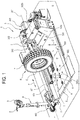
Figure 1 is a perspective view of a possible embodiment of a machine according to this description in a first operating configuration; -
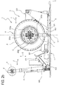
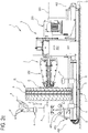
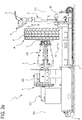
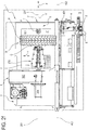
Figures 2a-2f are respective views of the same possible embodiment in a second operating configuration; -
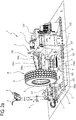
Figure 3 is a perspective view of the same possible embodiment in a third operating configuration; -
Figure 4 is a perspective view of the same possible embodiment in a fourth operating configuration, showing by way of example a possible wheel size on which the same embodiment can operate. - The accompanying drawings show a
tyre changing machine 1 according to a possible embodiment of this description. In the operating configurations of it illustrated in the accompanying drawings, thetyre changing machine 1 is operatively rested on a supporting surface S. - The machine comprises a wheel-
holder unit 2. In this application, the term "wheel" may denote either only the respective rim C or the entire wheel R, including the rim C and the tyre P mounted and/or at least partly or completely mounted to the rim C. - The wheel-
holder unit 2 defines a locking axis. The wheel-holder unit 2 is configured to hold the wheel R in a locked condition where the locking axis operatively coincides with a central axis of the wheel R. The wheel-holder unit 2 is configured to set the wheel R, when operatively in the locked condition, in rotation about an axis ofrotation 201. - In the embodiments shown in the accompanying drawings, the axis of
rotation 201 coincides with the locking axis. In the operating configurations of themachine 1 shown in the accompanying drawings, the axis ofrotation 201 is operatively transverse, or at right angles, to gravity. In these operating configurations of themachine 1, the axis ofrotation 201 is parallel to the supporting surface S. - The wheel-
holder unit 2 comprises a self-centringdevice 202. The self-centringdevice 202 comprises a plurality ofjaws 202a for clamping the rim C and hence the wheel R. - The wheel-
holder unit 2 comprises amotor drive system 203 to set the self-centringdevice 202 in rotation about the axis ofrotation 201, so the self-centringdevice 202 moves the wheel R and/or the rim C along with it in rotation about the axis ofrotation 201. The axis ofrotation 201 operatively coincides with the axis of the wheel R or of the rim C. - The
machine 1 comprises a frame T adapted to be rested on the supporting surface S in such a way as to remain preferably fixed relative to the supporting surface S. - The machine comprises a
bed 5 configured and/or adapted to be rested on the supporting surface S. Thebed 5 is configured to remain fixed relative to that supporting surface S and on top of the supporting surface S during operation of themachine 1. - The
bed 5 may be operatively fixed relative to the supporting surface but only rested on the supporting surface S itself. - The
bed 5 might also be operatively attached and/or coupled to the supporting surface S. - The
bed 5 is thus operatively fixed on the supporting surface S. - The bed comprises and/or defines a
floorplate 501. The floorplate is preferably treadable and surmountable by a wheel R and/or a tyre P. - The
floorplate 501 extends along a placement surface S' of thefloorplate 501 itself. - In an example embodiment of the
machine 1, the placement surface S' is parallel to the axis ofrotation 201. Thefloorplate 501 is configured to receive and support on it the wheel R complete with rim C and tyre P or the tyre P after it has been removed from the rim C. Thefloorplate 501 is treadable. - In the operating configurations of the
machine 1 shown in the accompanying drawings, the placement surface S' of thefloorplate 501 is parallel to the supporting surface S. - The
bed 5, and thus also thefloorplate 501, are preferably operatively fixed relative to the frame T of themachine 1 and/or form part of the frame T. - The axis of
rotation 201 is oriented along a longitudinal direction. The longitudinal direction is preferably parallel to thefloorplate 501. - The machine comprises a
drive system 3 configured to move the wheel-holder unit 2. - The
drive system 3 is configured to move the wheel-holder unit 2 along a trajectory having at least one longitudinal translational component (indicated by the double arrow X in the non-limiting example illustrated). - In one embodiment, the longitudinal translational component is operatively parallel to the axis of
rotation 201. In one embodiment, the longitudinal translational component is transverse, or at right angles, to gravity and may be considered as a "horizontal" translational component (in the sense that the longitudinal direction is oriented horizontally relative to the weight force); the transverse direction is perpendicular, or substantially perpendicular, to the longitudinal direction. - In one embodiment, the
drive system 3 is configured to move the wheel-holder unit 2 along a trajectory having at least a first transverse translational component (indicated by the double arrow Z in the non-limiting example illustrated). - The first transverse translational component is transverse to the axis of
rotation 201. In one embodiment, the first transverse translational component is at right angles to the axis ofrotation 201. In one embodiment, the first transverse translational component is parallel to gravity, in which case it may be considered as a "vertical" translational component. - In one embodiment, the
drive system 3 is configured to move the wheel-holder unit 2 along a trajectory having at least a second transverse translational component (indicated by the double arrow Y in the non-limiting example illustrated). - The second transverse translational component is transverse to the axis of
rotation 201. In one embodiment, the second transverse translational component is at right angles to the axis ofrotation 201. In one embodiment, the second transverse translational component is operatively transverse, or at right angles, to gravity, in which case it may be considered as a "lateral" translational component. - In one embodiment, the
drive system 3 is configured to move the wheel-holder unit 2 along (any one or) each of the aforementioned translational components; in one embodiment, thedrive system 3 is configured to move the wheel-holder unit 2 along any combination of the aforementioned translational components. For example, thedrive system 3 may cause the wheel-holder unit 2 to perform a movement which simultaneously comprises the first transverse component and the second transverse component. - In an example embodiment of the
machine 1, thedrive system 3 is also configured to cause the wheel-holder unit 2 to perform at least one longitudinal movement relative to thebed 5 and/or to the supporting surface S and/or to thefloorplate 501. This longitudinal movement is performed along the axis ofrotation 201 and comprises the longitudinal translational component. - This longitudinal movement may be, for example, along the direction indicated by the double arrow X.
- The
drive system 3 comprises afirst slide 301 which the wheel-holder unit 2 is connected to or mounted on. - The
machine 1 may comprise an actuator (for example, hydraulic), not illustrated, to move thefirst slide 301 translationally parallel to the axis ofrotation 201. The translational movement of thefirst slide 301 parallel to the axis ofrotation 201 in turn produces a translational movement of the wheel-holder unit 2 along the axis ofrotation 201. - In an example embodiment of the
machine 1, thedrive system 3 is also configured to cause the wheel-holder unit 2 to perform at least one transverse movement relative to thebed 5 and/or to the supporting surface S and/or to thefloorplate 501. This transverse movement is performed transversely or at right angles to the axis ofrotation 201 and may comprise at least one of the aforementioned transverse translational components. - This transverse movement may be, for example, along the direction indicated by the double arrow Y or by the double arrow Z.
- In the operating configuration shown in the accompanying drawings, the double arrow Y indicates a translational movement at right angles to the axis of
rotation 201 and to gravity, and the double arrow Z a translational movement at right angles to the axis ofrotation 201 and parallel to gravity. In the operating configuration shown in the accompanying drawings, the drive system can generate a movement in which the translations in the directions indicated by the arrows Z and Y are performed simultaneously, producing, for example, a curved or even circular movement. - The
drive system 3 comprises an articulatedarm 302 to impart to the wheel-holder unit 2 a movement comprising at least one of the aforementioned transverse translational components. - The wheel-
holder unit 2 is connected to, or mounted on, the articulatedarm 302. - In an example embodiment of the
machine 1, the articulatedarm 302 is in turn operatively interposed between the wheel-holder unit 2 and thefirst slide 301. The wheel-holder unit 2 is thus connected to, or mounted on, thefirst slide 301 by interposition of the articulatedarm 302. - The
machine 1 comprises an actuator or a motor, not illustrated, to generate a movement of the articulatedarm 302. This movement of the articulatedarm 302 in turn causes the wheel-holder unit 2 to move transversely or at right angles to the axis ofrotation 201, for example along the directions indicated by the double arrow Z or by the double arrow Y, or along the combination of the directions indicated by arrows Z and Y. - The articulated arm may comprise a
first portion 302a, which is preferably fixed relative to thefirst slide 301, and a second,movable portion 302b to generate this movement of the wheel-holder unit 2 transverse to the axis ofrotation 201. The second,movable portion 302b may, for example, rotate relative to thefirst portion 302a to generate this movement transverse to the axis ofrotation 201 of the wheel-holder unit 2. - In an example embodiment of the
machine 1, thedrive system 3 is configured to move the wheel-holder unit 2 transversely or at right angles to the axis ofrotation 201 and towards/away from thefloorplate 501, for example as indicated by the double arrow Z. - The
machine 1 comprises a tool-holder turret 4. - The
turret 4 may adopt a non-operating (that is, rest) condition, shown in all the drawings exceptFigure 4 , and an operating (that is, working) condition, shown inFigure 4 . - The machine also comprises at least one tool adapted to interact with the wheel tyre in order to perform mounting, removal or bead breaking operations on the tyre relative to the rim.
- The at least one tool is mounted on the
turret 4, which is configured to support the at least one tool in at least one operating position. - In one embodiment, the machine comprises at least one
bead breaker tool 8; in one embodiment, the machine comprises at least one mounting or removal tool 8'. - In one embodiment, the machine comprises at least the
bead breaker tool 8 and the mounting and/or removal tool 8'. - In such case, both the
bead breaker tool 8 and the mounting and/or removal tool 8' are mounted on theturret 4. - The
turret 4 is configured to move the at least onetool 8, 8' between a working position, where it operates on the tyre, and a rest position, where the tool is clear of the tyre. - In the operating work position, the at least one
tool 8 or 8' is adapted to perform, in conjunction with the wheel-holder unit 2, at least one operation relating to the mounting or removal of the tyre P to or from the rim C. - In one embodiment, the tool-
holder turret 4 is movable along the longitudinal direction; in one embodiment, the tool-holder turret 4 is also movable to move the at least onetool 8 or 8' transversely to the longitudinal direction and towards and away from the tyre (for example, radially). - In one embodiment, the
turret 4 can move thetools 8 and 8' about an axis along which theturret 4 itself extends. - The
turret 4 is movably connected to, or mounted on, thebed 5. - In an example embodiment, the
machine 1 may comprise arotation system 403 to cause a rotation of theturret 4. - In the embodiment shown in the accompanying drawings, the
turret 4 is movable between the non-operating condition and the operating condition by means of therotation system 403. - The
rotation system 403 for example comprises a hinge defining an axis of rotation and an actuator configured to rotate theturret 4 about the hinge. - In an example embodiment, the machine comprises a
second slide 401. Theturret 4 is mounted on, or connected to, thesecond slide 401. - In an example embodiment of the
machine 1, thesecond slide 401 is in turn operatively interposed between theturret 4 and thebed 5. - The
machine 1 may comprise an actuator (for example, hydraulic), not illustrated, to move thesecond slide 401 translationally parallel to or along an axis oftranslation 402. The translational movement of thesecond slide 401 parallel to or along the axis oftranslation 402 in turn produces a translational movement of theturret 4 along the axis oftranslation 402. - The axis of rotation about which the
turret 4 is movable between its non-operating condition and its operating condition may be parallel to, or coincident with, the axis oftranslation 402. In the non-limiting example illustrated, this rotation is indicated by the arrow F. - The
rotation system 403 is preferably integral with the translation of thesecond slide 401 along the axis oftranslation 402. - The
turret 4 is thus connected to (or mounted on) thebed 5 by interposition of thesecond slide 401 and/or of therotation system 403. - The
machine 1 comprises at least one tool-holder arm 6. The tool-holder arm 6 is configured to mount (at least) one further tool 7 (for example, a removal tool, a mounting tool or a bead breaker tool). - In one embodiment, the tool-
holder arm 6 and thefurther tool 7 are operatively coupled (with thefurther tool 7 in a mounting position) rigidly in such a way as to form a rigid unit. - It should be noted that the expression "further tool" is used in this document to distinguish the
tool 7 mounted on the tool-holder arm 6 from the at least onetool 8 mounted on theturret 4. - The tool-
holder arm 6 can be anchored (fixed) directly to thefloorplate 501. The tool-holder arm 6 can be removably anchored (fixed) directly to thefloorplate 501. - In one embodiment, the tool-
holder arm 6 and the correspondingfurther tool 7 are irremovably attached to each other to form a single part; in another embodiment, the tool-holder arm 6 and the correspondingfurther tool 7 are detachable from each other. - In one embodiment, the tool-
holder arm 6 is a rigid member; preferably, the tool-holder arm 6 is a rod-shaped member. - In one embodiment, the
machine 1 comprises a plurality (two or more) tool-holder arms 6; the numeral 6' in the accompanying drawings denotes a tool-holder arm provided in addition to the tool-holder arm 6. The machine might also comprise a corresponding plurality offurther tools 7, each coupled to a corresponding tool-holder arm 6; the numeral 7' in the drawings denotes a further tool additional to thefurther tool 7. - The
machine 1 comprises at least one connectingmember 502 situated on thefloorplate 501 and configured to allow the tool-holder arm 6 to be connected (that is, fixed or anchored) to thefloorplate 501. The connectingmember 502 is situated on thefloorplate 501 at a fixed position relative to the floorplate 501 (that is, relative to the bed 5) and thus stationary relative to a movement of the wheel-holder unit 2 (and relative to a movement of the turret 4). - The at least one
further tool 7 is thus fixable to thefloorplate 501 by means of the tool-holder arm 6 and the at least one connectingmember 502, so as to be rigidly connected to thefloorplate 501 at a predetermined position defined by the position of the connectingmember 502. - Operatively, the at least one
further tool 7, fixed directly and rigidly to thefloorplate 501 by means of the tool-holder arm 6 and the connectingmember 502, acts jointly with the wheel-holder unit 2 to interact with the tyre to perform at least one of the operations relating to mounting or removing the tyre P (bead breaking, mounting or removal). - In one embodiment, the tool-
holder arm 6 or 6' has a first and a second end. The first end is operatively connected to thefurther tool 7 or 7'; the other end is operatively connected directly to thefloorplate 501 of thebed 5. - It should be noted that the at least one connecting
member 502 is configured to be coupled to the tool-holder arm 6 positioned transversely to thefloorplate 501, in such a way that the tool-holder arm 6 projects from thefloorplate 501 at right angles to thebed 5, that is, to the placement surface S' (and also to thefloorplate 501 itself). - In one embodiment, the connecting
member 502 is disposed along an axis of placement H in a vertical plane. The axis of placement H is preferably parallel to the placement surface S' of thefloorplate 501 or to thefloorplate 501. - The vertical plane is a plane parallel to the axis of
rotation 201 and transverse or at right angles to the placement surface S' of thefloorplate 501 or to thefloorplate 501. - The vertical plane may (but not necessarily must) contain the axis of
rotation 201. - The trace of the vertical plane is labelled "V" in the drawings.
- In an example embodiment, the axis of placement H is defined by the intersection of this vertical plane with the
floorplate 501 or the placement surface S' thereof. - In an example embodiment of the
machine 1, the axis oftranslation 402 of theturret 4 is situated laterally and externally of this vertical plane. - In an example embodiment of the
machine 1, the connectingmember 502 comprises ahole 502a. Thehole 502a is made in thefloorplate 501 and is adapted to receive the tool-holder arm 6 in a direction transverse or at right angles to thefloorplate 501 or to the placement surface S' of thefloorplate 501. - The
machine 1 may comprise means for coupling or attaching or fixing the tool-holder arm 6 or 6' to or in thehole 502a. - These coupling or attaching or fixing means may be integral with the
hole 502a or with the tool-holder arm 6 or 6'. - The
machine 1 might also comprise a reinforcing structure configured to reinforce the tool-holder arm 6 in order to better release the forces generated when thefurther tool 7 acts jointly with the wheel-holder unit 2 to remove or mount the tyre P. More specifically, during the joint action between thefurther tool 7 and the wheel-holder unit 2, the wheel-holder unit 2 might be driven by thefirst slide 301 and/or by the articulatedarm 302, thereby increasing the intensity of the forces acting on the tool-holder arm 6. - The
further tool 7 may be, for example, a bead breaker tool or a tyre changing tool. The further tyre changing tool comprises a claw-like or hook-shaped lever. This lever is adapted to engage the bead of the tyre P. In a possible embodiment of themachine 1, themachine 1 comprises a plurality of tool-holder arms 6, which may also be more than two. - The
machine 1 may comprise a plurality of further tools 7 (for example, removal tools, mounting tools or bead breaker tools). - The
machine 1 is configured in such a way that each respective tool-holder arm 6 can be connected or fixed, preferably in removable manner, to thefloorplate 501. - In a possible embodiment, the
machine 1 comprises a plurality of connectingmembers 502 situated on the floorplate. These connectingmembers 502 are situated on thefloorplate 501 at respective predetermined or fixed positions relative to thefloorplate 501 itself (unlike the wheel-holder unit 2 and theturret 4, which are movable relative to the floorplate 501). - This allows simultaneously fixing a plurality of
further tools 7 to thefloorplate 501 by means of a corresponding plurality of tool-holder arms 6 and/or allows fixing onefurther tool 7 by means of a corresponding tool-holder arm 6 in a plurality of different positions defined on thefloorplate 501. - Each respective tool-
holder arm 6, when it is operatively fixed to thefloorplate 501 by means of a respective connectingmember 502, projects from thefloorplate 501 transversely or at right angles to thebed 5 or to the placement surface S' or to thefloorplate 501. - In a possible embodiment of the
machine 1, these connectingmembers 502 are disposed and distributed along the axis of placement H (that is to say, they are intersected by the vertical plane V). In a possible embodiment of themachine 1, these connectingmembers 502 are longitudinally spaced (preferably along the axis of placement H). - Each of these connecting
members 502 may comprise arespective hole 502a. - For each connecting
member 502, themachine 1 may comprise means for coupling or attaching or fixing the respective tool-holder arm 6 or 6' to or in therespective hole 502a. - These coupling or attaching or fixing means may be integral with the
respective hole 502a or with the respective tool-holder arm 6 or 6'. - In the first operating configuration of the
machine 1 shown inFigure 1 , there is only one tool-holder arm 6, which is fitted with a furtherbead breaker tool 7. The tool-holder arm 6 ofFigure 1 is fixed to thefloorplate 501 by means of the connectingmember 502. - In the second operating configuration of the
machine 1 shown inFigures 2a-2f , there are two tool-holder arms, both labelled 6, each fitted with abead breaker tool 7. The tool-holder arms 6 ofFigures 2a-2f are fixed to thefloorplate 501 by means of respective connectingmembers 502. - In the third operating configuration of the
machine 1 shown inFigure 3 , there is another tool-holder arm, labelled 6', which is fitted with a further tyre changing tool 7'. The tool-holder arm 6' is fixed to thefloorplate 501 by means of the connectingmember 502 ofFigure 3 . - In the
example floorplate 501 shown in the accompanying drawings, the floorplate mounts three connectingmembers 502 but there may be a different number of connecting members because themachine 1 according to this description is configured to operate with any number of tool-holder arms fitted with respective further tools and fixed to the floorplate by means of a corresponding number of respective connecting members. Each of these respective further tools may be of any type. - This description also provides a method for using the
tyre changing machine 1. - The method comprises a step of moving a wheel R or a rim C onto the
floorplate 501. In an example embodiment, this step is carried out by the tyre mechanic by moving the wheel by hand onto the floorplate. - The method then includes a step of driving the wheel-
holder unit 2 along the axis ofrotation 201 until intercepting the rim C to lock the wheel R to the wheel-holder unit 2. - The wheel-
holder unit 2, with the wheel R or the rim C locked thereto, is lifted off thefloorplate 501. - The tyre mechanic selects the tool to be used. For this purpose, there are two options.
- In a first option, the tyre mechanic can use the tool 8 (or the
tools 8 or 8') associated with the turret 4: in this case, the tyre mechanic can proceed to moving the turret from its non-operating condition to its operating condition so as to place thetool 8 or 8' in its working position. Moving theturret 4 from its non-operating condition to its operating condition can be done, for example, by operating an actuator. - When the
turret 4 is in its operating condition, at least onetool 8 or 8' mounted on theturret 4 is in its working position where it can interact with the tyre P and/or the rim C. - In the second option, the tyre mechanic can decide to use the further tool 7' connected to the tool-holder arm 6'.
- The further tools not used are kept at suitable positions where they do not interfere with subsequent operations.
- In this case, the tyre mechanic proceeds to fixing at least one tool-
holder arm 6 or 6' to thefloorplate 501 at a predetermined, stationary position (in such a way that the tool-holder arm 6 projects from thefloorplate 501 transversely to the placement surface S'). - The tool-
holder arm 6 is fixed to thefloorplate 501 by means of at least one connectingmember 502. - To do this, the
arm 6 or 6' is inserted and fixed in at least onehole 502a. - When at least one tool-
holder arm 6 or 6' is fixed to thefloorplate 501, at least onefurther tool 7 or 7' mounted on the at least one tool-holder arm 6 or 6' is in its working position where it can interact with the tyre P and/or the rim C. - Before the tool-
holder arm 6 is fixed in this way, the tool-holder arm 6 is at a rest position, clear of thefloorplate 501, especially the portion of thefloorplate 501 in front of the wheel-holder unit 2; thus, thefloorplate 501 is left clear to move the wheel onto thefloorplate 501. - The method then includes a step of driving the wheel-
holder unit 2, with the wheel R or the rim C locked thereto, along the axis ofrotation 201 towards thefurther tool 7 of the tool-holder arm 6, to perform the at least one operation by joint action between the wheel-holder unit 2, which is movable, and the (further)tool 7, which is stationary. - If a
tool 8 of theturret 4 is used, the next step is to move the tool-holder turret 4 relative to the wheel-holder unit 2 parallel to the axis ofrotation 201 in order to allow interaction between the tyre P and thetool 8. In this case, there are several possible options for the horizontal movement: it may be imparted only to the wheel-holder unit 2 (theturret 4 remains motionless, that is, stationary), or it may be imparted only to the turret 4 (the wheel-holder unit 2 remains motionless, that is, stationary), or it may be imparted to both theturret 4 and the wheel-holder unit 2. Obviously, the rotational movement of the wheel R or rim C about its axis (performed during the operation on the tyre according to a known method) is necessarily performed by the wheel-holder unit 2. - Operatively, the (further)
tool 7 mounted on the tool-holder arm 6 in its operating work position is situated at a first height relative to thefloorplate 501. On the other hand, thetool 8 or 8' mounted on theturret 4 in its operating work position is situated at a second height relative to thefloorplate 201. The second height is greater than the first height. Thus, in a possible method of use, the tyre mechanic can use the tool-holder arm 6 for relatively small wheels and theturret 4 for relatively large wheels.Figure 4 shows an operator O of average height from behind to indicate a possible large wheel size which themachine 1 can work on.
Claims (14)
- An apparatus (1) for mounting and removing a tyre operatively resting on a supporting surface (S), comprising:- a wheel-holder unit (2) configured to lock a wheel (R) and to set the wheel in rotation about a horizontal axis of rotation (201) operatively at right angles to gravity and parallel to the supporting surface (S);- a bed (5) operatively fixed on the supporting surface (S) and defining a floorplate (501) which extends along its placement surface (S') parallel to the axis of rotation (201) and to the supporting surface (S) to receive and support the wheel (R) resting on it;- a drive system (3) configured to move the wheel-holder unit (2) along the axis of rotation (201);- a tool-holder turret (4) movably connected to the bed (5) and adapted to support at least one tool (8; 8') to keep it in an operating work position where it can interact with a tyre (P) of the wheel (R);characterized in that it comprises:- at least one tool-holder arm (6) connected to a further tool (7; 7');- at least one connecting member (502) situated on the floorplate (501) at a fixed, stationary position, where the at least one tool-holder arm (6) is removably fixable to the floorplate (501), by means of the connecting member (502) in such a way that the arm projects from the floorplate (501) transversely to the placement surface (S') and holds the further tool (7; 7') in an operating work position where it can interact with the tyre (P).
- The apparatus (1) according to claim 1, wherein the connecting member (502) is disposed along a longitudinal axis of placement (H) in a vertical plane (V), the vertical plane being parallel to the axis of rotation (201) or aligned with the axis of rotation (201) and being transverse to the placement surface (S').
- The apparatus (1) according to claim 2, comprising a slide (401) on which the turret (4) is mounted, the slide (401) being configured to move the turret (4) translationally relative to the bed (5) by translation of the slide (401) along the axis of translation (402), the axis of translation (402) being situated laterally of, and spaced from, the vertical plane (V).
- The apparatus (1) according to any one of the preceding claims, wherein the turret (4) is movable towards and away from the axis of rotation (201) in order to move the at least one tool (8; 8') between the operating work position and a rest position where the tool (8; 8') is clear of the tyre (P).
- The apparatus (1) according to any one of the preceding claims, wherein the drive system (3) is configured to move the wheel-holder unit (2) towards and away from the floorplate (501).
- The apparatus (1) according to any one of the preceding claims, wherein the connecting member (502) comprises a hole (502a) made in the floorplate (501) and adapted to receive the tool-holder arm (6) in a direction transverse to the placement surface (S').
- The apparatus (1) according to any one of the preceding claims, wherein the at least one tool (8; 8') or the at least one further tool (7; 7') is a tool (7'; 8') for mounting or removing the tyre (P) or a bead breaker tool (7; 8).
- The apparatus (1) according to any one of the preceding claims, wherein the working position of the at least one further tool (7; 7') is situated at a first height relative to the floorplate (501) and the working position of the at least one tool (8; 8') is situated at a second height relative to the floorplate (501), the second height being greater than the first height.
- The apparatus (1) according to any one of the preceding claims, comprising:- a plurality of tool-holder arms (6; 6') adapted to support a plurality of respective further tools (7; 7');- a plurality of connecting members (502) situated on the floorplate (501) at respective fixed positions;wherein the tool-holder arms (6; 6') are removably fixable to the bed (5) by means of the respective connecting members (502), in such a way that the tool-holder arms (6; 6') project from the bed transversely to the placement surface (S') and keep the respective further tools (7; 7') at respective working positions where they can interact with the tyre (P).
- The apparatus (1) according to claim 9, wherein the connecting members (502) are disposed and distributed along a longitudinal axis of placement (H) in a vertical plane (V), the vertical plane being parallel to the axis of rotation (201) or aligned with the axis of rotation (201) and being transverse to the placement surface (S').
- A method for using an apparatus configured to automatically carry out at least one operation relating to the removal or mounting of a tyre (P) of a vehicle wheel (R) respectively from and to a rim (C), the method comprising the following steps:- preparing a wheel-holder unit (2) defining a horizontal axis of rotation (201) of the wheel-holder unit (2);- preparing on the supporting surface (S) a bed (5) which is fixed on the supporting surface (S) and which defines a floorplate (501) extending along a placement surface (S') parallel to the horizontal axis of rotation (201);- preparing a tool-holder turret movably connected to the bed (5), the turret (4) supporting at least one tool (8; 8');- moving the wheel (R) or the rim (C) onto the floorplate (501);- driving the wheel-holder unit (2) along the axis of rotation (201) until intercepting the rim (C) of the wheel (R) and locking the wheel (R) or the rim (C) in a locked condition on the wheel-holder unit (2);- driving the wheel-holder unit (2), with the wheel (R) or the rim (C) in the locked condition on the wheel-holder unit (2), away from the floorplate (501);- fixing at least one tool-holder arm (6; 6') to the floorplate (501) at a predetermined, stationary position, by means of at least one connecting member (502), in such a way that the tool-holder arm (6; 6') projects from the floorplate (501) transversely to the placement surface (S'), the tool-holder arm (6; 6') mounting at least one further tool (7; 7') in an operating work position;- driving the wheel-holder unit (2), and hence also the wheel (R) or the rim (C), along the axis of rotation (201) and relative to the at least one further tool (7; 7'), to perform the at least one operation by joint action between the wheel-holder unit (2) and the at least one further tool (7; 7') operating on the tyre (P).
- The method according to claim 11, wherein the at least one further tool (7; 7') mounted on the tool-holder arm (6; 6') in its working position is situated at a first height relative to the floorplate (501) and the at least one tool (8; 8') mounted on the turret (4) in its working position is situated at a second height relative to the floorplate (501), the second height being greater than the first height.
- The method according to claim 11 or 12, comprising a step of fixing a first and a second tool-holder arm (6; 6') to the floorplate (501) at respective, stationary positions on opposite sides of the wheel (R) relative to the longitudinal direction.
- The method according to any one of claims 11 to 13, comprising a step of substituting the further tool (7; 7') with another further tool (7; 7') of different shape, by disengaging and engaging the respective tool-holder arms (6; 6') from and to the connecting member (502).
Applications Claiming Priority (1)
| Application Number | Priority Date | Filing Date | Title |
|---|---|---|---|
| IT102016000111370A IT201600111370A1 (en) | 2016-11-04 | 2016-11-04 | APPARATUS FOR MOUNTING AND DISASSEMBLING A TIRE |
Publications (2)
| Publication Number | Publication Date |
|---|---|
| EP3323644A1 true EP3323644A1 (en) | 2018-05-23 |
| EP3323644B1 EP3323644B1 (en) | 2019-07-10 |
Family
ID=58010304
Family Applications (1)
| Application Number | Title | Priority Date | Filing Date |
|---|---|---|---|
| EP17199669.7A Active EP3323644B1 (en) | 2016-11-04 | 2017-11-02 | Apparatus for mounting and removing a tyre |
Country Status (5)
| Country | Link |
|---|---|
| US (1) | US20180126807A1 (en) |
| EP (1) | EP3323644B1 (en) |
| CN (1) | CN108016221B (en) |
| ES (1) | ES2748670T3 (en) |
| IT (1) | IT201600111370A1 (en) |
Cited By (2)
| Publication number | Priority date | Publication date | Assignee | Title |
|---|---|---|---|---|
| IT201800009322A1 (en) * | 2018-10-10 | 2020-04-10 | Butler Eng And Marketing Spa | MACHINE FOR ASSEMBLY AND / OR DISASSEMBLY OF VEHICLE WHEELS, IN PARTICULAR TRUCK WHEELS |
| IT201800020740A1 (en) * | 2018-12-21 | 2020-06-21 | Gino Ferrari | UNIVERSAL TIRE CHANGING MACHINE |
Families Citing this family (5)
| Publication number | Priority date | Publication date | Assignee | Title |
|---|---|---|---|---|
| CN110001314A (en) * | 2019-05-06 | 2019-07-12 | 山东大学深圳研究院 | Waste and old bicycle tyre detaching equipment |
| CN113103832B (en) * | 2021-04-22 | 2022-02-01 | 南京沃宇机电有限公司 | Vertical tire dismouting robot |
| CN116409094B (en) * | 2021-12-29 | 2025-11-21 | 明门(中国)幼童用品有限公司 | Imitated inflatable wheel assembling jig |
| CN114604045B (en) * | 2022-03-16 | 2023-06-23 | 临夏海螺水泥有限责任公司 | A tire auxiliary dismounting device |
| CN114919344A (en) * | 2022-06-09 | 2022-08-19 | 营口辽南德威机械设备有限公司 | A vertical tire changer with a double-sided tool head and a flip structure |
Citations (4)
| Publication number | Priority date | Publication date | Assignee | Title |
|---|---|---|---|---|
| JP2010285059A (en) | 2009-06-11 | 2010-12-24 | Onodani Kiko Kk | Tool telescopic / reversing mechanism in tire attaching / detaching device |
| EP2282898B1 (en) | 2008-04-21 | 2011-11-30 | CORGHI S.p.A. | A tyre-changing machine and a relative bead-breaking method |
| WO2014037771A1 (en) | 2012-09-04 | 2014-03-13 | M&B Engineering S.R.L. | Tyre-changing machine |
| CN105799433A (en) | 2016-06-07 | 2016-07-27 | 营口通广汽车保修设备有限公司 | Large tire changer |
Family Cites Families (28)
| Publication number | Priority date | Publication date | Assignee | Title |
|---|---|---|---|---|
| US2201982A (en) * | 1935-07-13 | 1940-05-28 | Wintercorn Andrew F | Combination tire changer and wheel balancer and tool therefor |
| US3489198A (en) * | 1967-01-25 | 1970-01-13 | Sylvester William Malinski | Method and apparatus for mounting and removing pneumatic tires |
| US3827474A (en) * | 1973-01-30 | 1974-08-06 | Magnum Automotive Equip | Power column latch |
| DE2648897C2 (en) * | 1976-10-28 | 1982-10-07 | Wilhelm 6349 Herbornseelbach Schäfer | Machine for assembling and disassembling vehicle tires |
| CA1117858A (en) * | 1978-01-23 | 1982-02-09 | Leslie Bubik | Tire-changing apparatus with bead breaker mechanism |
| BE881190A (en) * | 1980-01-17 | 1980-05-16 | Quesne Francis Du | DEVICE FOR HANDLING WHEELS AND TIRES IN AN APPARATUS FOR MOUNTING AND DISASSEMBLING TIRES |
| EP0338642A3 (en) * | 1988-04-20 | 1990-05-30 | du Quesne, Francis | Apparatus for mounting automotive vehicle tyres |
| US5555922A (en) * | 1995-04-18 | 1996-09-17 | Brunner; Larry F. | Tire bead breaking tool |
| IT1289137B1 (en) * | 1996-10-22 | 1998-09-25 | Butler Eng & Marketing | TIRE CHANGER MACHINE |
| IT1310170B1 (en) * | 1999-02-04 | 2002-02-11 | Giuliano Srl | MACHINE FOR THE ASSEMBLY AND DISASSEMBLY OF SPECIAL TYPE TIRES |
| IT1310590B1 (en) * | 1999-05-14 | 2002-02-19 | Giuliano Srl | MULTIFUNCTIONAL STATION FOR THE ASSEMBLY AND DISASSEMBLY OF DIPNEUMATICS BOTH CONVENTIONAL AND SPECIAL. |
| ITMO20030132A1 (en) * | 2003-05-09 | 2004-11-10 | Giuliano Srl | MACHINE FOR THE ASSEMBLY AND DISASSEMBLY OF TIRES AND WHEEL RIMS FOR VEHICLES. |
| US7621311B2 (en) * | 2005-10-05 | 2009-11-24 | Android Industries Llc | Tire-wheel assembly adjuster |
| ITMO20070350A1 (en) * | 2007-11-21 | 2009-05-22 | Giuliano Spa | MACHINE FOR ASSEMBLY AND DISASSEMBLY OF WHEEL TIRES FOR VEHICLES |
| ITMO20070349A1 (en) * | 2007-11-21 | 2009-05-22 | Giuliano Spa | MACHINE FOR ASSEMBLY AND DISASSEMBLY OF WHEEL TIRES FOR VEHICLES |
| US8770254B1 (en) * | 2008-07-17 | 2014-07-08 | Hunter Engineering Company | Tire changer with rotational position and tracking control |
| US9434219B1 (en) * | 2008-01-25 | 2016-09-06 | Hunter Engineering Co. | Automated tire changer machine, systems, programs and methods |
| ITVR20080050A1 (en) * | 2008-04-28 | 2009-10-29 | Butler Eng & Marketing | BREAKER GROUP FOR A TIRE CHANGER MACHINE |
| WO2009148544A2 (en) * | 2008-05-29 | 2009-12-10 | Djm Technologies, Llc | Tire run-flat ring removal and installation machine |
| IT1402585B1 (en) * | 2010-10-22 | 2013-09-13 | Maioli | TANK MACHINE. |
| IT1403494B1 (en) * | 2010-12-23 | 2013-10-17 | Butler Eng & Marketing | DISASSEMBLY DEVICE OF THE SECOND HEEL OF A TIRE FROM A RIM AND ITS RELATION METHOD |
| ITBO20110300A1 (en) * | 2011-05-24 | 2012-11-25 | Corghi Spa | A CENTERING DEVICE FOR THE RIM OF A WHEEL ON THE WHEEL-HOLDING ASSEMBLY OF A TIRE CHANGER MACHINE. |
| ITVR20120159A1 (en) * | 2012-08-01 | 2014-02-02 | Butler Engineering And Marketing S P A | DISMANTLING DEVICE OF A TIRE FROM A RIM AND METHOD OF DISASSEMBLY OF A WHEELED WHEEL |
| EP2711206B1 (en) * | 2012-09-25 | 2015-08-26 | Snap-on Equipment Srl a unico socio | Apparatus for servicing vehicle wheels |
| EP3501862B1 (en) * | 2014-05-30 | 2022-08-03 | Snap-on Equipment Srl a unico socio | Method for mounting and demounting a tyre to and from a wheel rim |
| ES2676497T3 (en) * | 2015-02-09 | 2018-07-20 | Snap-On Equipment S.R.L. | Device for raising at least one wheel or tire of a vehicle, with a detector of the state of wear of the latter |
| IT201700055380A1 (en) * | 2017-05-22 | 2018-11-22 | Nexion Spa | REMOVAL METER SYSTEM, SUITABLE FOR INSTALLATION ON A MOTORIZED VEHICLE, AND A TIRE DISASSEMBLY METHOD |
| US11155129B2 (en) * | 2018-03-21 | 2021-10-26 | Hunter Engineering Company | Wheel clamp assembly for semi-autonomous tire changer machine |
-
2016
- 2016-11-04 IT IT102016000111370A patent/IT201600111370A1/en unknown
-
2017
- 2017-10-30 US US15/797,803 patent/US20180126807A1/en active Pending
- 2017-11-02 EP EP17199669.7A patent/EP3323644B1/en active Active
- 2017-11-02 ES ES17199669T patent/ES2748670T3/en active Active
- 2017-11-03 CN CN201711069837.1A patent/CN108016221B/en active Active
Patent Citations (4)
| Publication number | Priority date | Publication date | Assignee | Title |
|---|---|---|---|---|
| EP2282898B1 (en) | 2008-04-21 | 2011-11-30 | CORGHI S.p.A. | A tyre-changing machine and a relative bead-breaking method |
| JP2010285059A (en) | 2009-06-11 | 2010-12-24 | Onodani Kiko Kk | Tool telescopic / reversing mechanism in tire attaching / detaching device |
| WO2014037771A1 (en) | 2012-09-04 | 2014-03-13 | M&B Engineering S.R.L. | Tyre-changing machine |
| CN105799433A (en) | 2016-06-07 | 2016-07-27 | 营口通广汽车保修设备有限公司 | Large tire changer |
Cited By (4)
| Publication number | Priority date | Publication date | Assignee | Title |
|---|---|---|---|---|
| IT201800009322A1 (en) * | 2018-10-10 | 2020-04-10 | Butler Eng And Marketing Spa | MACHINE FOR ASSEMBLY AND / OR DISASSEMBLY OF VEHICLE WHEELS, IN PARTICULAR TRUCK WHEELS |
| EP3636463A1 (en) | 2018-10-10 | 2020-04-15 | Butler Engineering & Marketing S.p.A. | Machine for mounting and/or removing vehicle tyres, in particular truck tyres |
| US11254174B2 (en) | 2018-10-10 | 2022-02-22 | Butler Engineering And Marketing S.P.A. | Machine for mounting and/or removing vehicle wheels, in particular truck wheels |
| IT201800020740A1 (en) * | 2018-12-21 | 2020-06-21 | Gino Ferrari | UNIVERSAL TIRE CHANGING MACHINE |
Also Published As
| Publication number | Publication date |
|---|---|
| US20180126807A1 (en) | 2018-05-10 |
| CN108016221A (en) | 2018-05-11 |
| IT201600111370A1 (en) | 2018-05-04 |
| ES2748670T3 (en) | 2020-03-17 |
| CN108016221B (en) | 2022-05-10 |
| EP3323644B1 (en) | 2019-07-10 |
Similar Documents
| Publication | Publication Date | Title |
|---|---|---|
| EP3323644B1 (en) | Apparatus for mounting and removing a tyre | |
| CN107856482B (en) | Tyre disassembling machine | |
| EP1157860B2 (en) | Automatic bead release device for tyre removal machines | |
| US8905112B2 (en) | Device for demounting the second bead of a tire from a rim and respective demounting method | |
| JP6632241B2 (en) | Apparatus for installing and / or removing tired wheel, tire installation and removal machine, and method for removing tire from rim of tired wheel | |
| KR101909442B1 (en) | Jig apparatus | |
| US20090035107A1 (en) | Tire Rotating Robot | |
| JP6788983B2 (en) | Vehicle wheel / tire installation / removal machine | |
| EP1897708A1 (en) | Machine for fitting and removing tyres and wheel rims for vehicles | |
| JP6729996B2 (en) | Device for removing a wheel with a tire, a tire mounting and removing machine, a method for removing a first bead of a tire, and a method for removing a tire | |
| JP2008542121A (en) | Machine for fixing wheels to the vehicle | |
| CN112423996B (en) | A robot device and method for maintaining wheels of a vehicle | |
| US20160052157A1 (en) | Punch for punching polymeric motor vehicle components | |
| JP4613476B2 (en) | Clamp jig | |
| CN206445415U (en) | A kind of fixture welded for car floor | |
| ES2924840T3 (en) | tire changing device | |
| US6192959B1 (en) | Machine for fitting and removing tires | |
| US20230123205A1 (en) | Machine for mounting and demounting a tyre relative to a corresponding rim and wheel servicing method | |
| CN105579254A (en) | Tyre-changing machine | |
| CN107378242B (en) | Kettle body laser marking welding machine | |
| CN107310277B (en) | Color card T-bar hook code printer | |
| CN113523161B (en) | Automatic tool changing device, multi-station spring machine and operation method | |
| EP1724129B1 (en) | A device for debeading tyres from wheels positioned on a turntable of a tyre-removing machine | |
| US9517667B2 (en) | Tire mounting tool assembly | |
| CN222857170U (en) | Multi-station welding positioner |
Legal Events
| Date | Code | Title | Description |
|---|---|---|---|
| PUAI | Public reference made under article 153(3) epc to a published international application that has entered the european phase |
Free format text: ORIGINAL CODE: 0009012 |
|
| STAA | Information on the status of an ep patent application or granted ep patent |
Free format text: STATUS: THE APPLICATION HAS BEEN PUBLISHED |
|
| AK | Designated contracting states |
Kind code of ref document: A1 Designated state(s): AL AT BE BG CH CY CZ DE DK EE ES FI FR GB GR HR HU IE IS IT LI LT LU LV MC MK MT NL NO PL PT RO RS SE SI SK SM TR |
|
| AX | Request for extension of the european patent |
Extension state: BA ME |
|
| STAA | Information on the status of an ep patent application or granted ep patent |
Free format text: STATUS: REQUEST FOR EXAMINATION WAS MADE |
|
| REG | Reference to a national code |
Ref country code: DE Ref legal event code: R079 Ref document number: 602017005186 Country of ref document: DE Free format text: PREVIOUS MAIN CLASS: B60C0025050000 Ipc: B60C0025138000 |
|
| 17P | Request for examination filed |
Effective date: 20181120 |
|
| RBV | Designated contracting states (corrected) |
Designated state(s): AL AT BE BG CH CY CZ DE DK EE ES FI FR GB GR HR HU IE IS IT LI LT LU LV MC MK MT NL NO PL PT RO RS SE SI SK SM TR |
|
| RIC1 | Information provided on ipc code assigned before grant |
Ipc: B60C 25/132 20060101ALI20181204BHEP Ipc: B60C 25/138 20060101AFI20181204BHEP Ipc: B60C 25/05 20060101ALI20181204BHEP |
|
| GRAP | Despatch of communication of intention to grant a patent |
Free format text: ORIGINAL CODE: EPIDOSNIGR1 |
|
| STAA | Information on the status of an ep patent application or granted ep patent |
Free format text: STATUS: GRANT OF PATENT IS INTENDED |
|
| INTG | Intention to grant announced |
Effective date: 20190215 |
|
| GRAA | (expected) grant |
Free format text: ORIGINAL CODE: 0009210 |
|
| STAA | Information on the status of an ep patent application or granted ep patent |
Free format text: STATUS: THE PATENT HAS BEEN GRANTED |
|
| AK | Designated contracting states |
Kind code of ref document: B1 Designated state(s): AL AT BE BG CH CY CZ DE DK EE ES FI FR GB GR HR HU IE IS IT LI LT LU LV MC MK MT NL NO PL PT RO RS SE SI SK SM TR |
|
| REG | Reference to a national code |
Ref country code: GB Ref legal event code: FG4D |
|
| REG | Reference to a national code |
Ref country code: CH Ref legal event code: EP Ref country code: AT Ref legal event code: REF Ref document number: 1153161 Country of ref document: AT Kind code of ref document: T Effective date: 20190715 |
|
| REG | Reference to a national code |
Ref country code: DE Ref legal event code: R096 Ref document number: 602017005186 Country of ref document: DE |
|
| REG | Reference to a national code |
Ref country code: IE Ref legal event code: FG4D |
|
| REG | Reference to a national code |
Ref country code: NL Ref legal event code: MP Effective date: 20190710 |
|
| REG | Reference to a national code |
Ref country code: LT Ref legal event code: MG4D |
|
| REG | Reference to a national code |
Ref country code: AT Ref legal event code: MK05 Ref document number: 1153161 Country of ref document: AT Kind code of ref document: T Effective date: 20190710 |
|
| PG25 | Lapsed in a contracting state [announced via postgrant information from national office to epo] |
Ref country code: LT Free format text: LAPSE BECAUSE OF FAILURE TO SUBMIT A TRANSLATION OF THE DESCRIPTION OR TO PAY THE FEE WITHIN THE PRESCRIBED TIME-LIMIT Effective date: 20190710 Ref country code: FI Free format text: LAPSE BECAUSE OF FAILURE TO SUBMIT A TRANSLATION OF THE DESCRIPTION OR TO PAY THE FEE WITHIN THE PRESCRIBED TIME-LIMIT Effective date: 20190710 Ref country code: PT Free format text: LAPSE BECAUSE OF FAILURE TO SUBMIT A TRANSLATION OF THE DESCRIPTION OR TO PAY THE FEE WITHIN THE PRESCRIBED TIME-LIMIT Effective date: 20191111 Ref country code: NL Free format text: LAPSE BECAUSE OF FAILURE TO SUBMIT A TRANSLATION OF THE DESCRIPTION OR TO PAY THE FEE WITHIN THE PRESCRIBED TIME-LIMIT Effective date: 20190710 Ref country code: BG Free format text: LAPSE BECAUSE OF FAILURE TO SUBMIT A TRANSLATION OF THE DESCRIPTION OR TO PAY THE FEE WITHIN THE PRESCRIBED TIME-LIMIT Effective date: 20191010 Ref country code: NO Free format text: LAPSE BECAUSE OF FAILURE TO SUBMIT A TRANSLATION OF THE DESCRIPTION OR TO PAY THE FEE WITHIN THE PRESCRIBED TIME-LIMIT Effective date: 20191010 Ref country code: AT Free format text: LAPSE BECAUSE OF FAILURE TO SUBMIT A TRANSLATION OF THE DESCRIPTION OR TO PAY THE FEE WITHIN THE PRESCRIBED TIME-LIMIT Effective date: 20190710 Ref country code: SE Free format text: LAPSE BECAUSE OF FAILURE TO SUBMIT A TRANSLATION OF THE DESCRIPTION OR TO PAY THE FEE WITHIN THE PRESCRIBED TIME-LIMIT Effective date: 20190710 Ref country code: HR Free format text: LAPSE BECAUSE OF FAILURE TO SUBMIT A TRANSLATION OF THE DESCRIPTION OR TO PAY THE FEE WITHIN THE PRESCRIBED TIME-LIMIT Effective date: 20190710 |
|
| PG25 | Lapsed in a contracting state [announced via postgrant information from national office to epo] |
Ref country code: IS Free format text: LAPSE BECAUSE OF FAILURE TO SUBMIT A TRANSLATION OF THE DESCRIPTION OR TO PAY THE FEE WITHIN THE PRESCRIBED TIME-LIMIT Effective date: 20191110 Ref country code: GR Free format text: LAPSE BECAUSE OF FAILURE TO SUBMIT A TRANSLATION OF THE DESCRIPTION OR TO PAY THE FEE WITHIN THE PRESCRIBED TIME-LIMIT Effective date: 20191011 Ref country code: RS Free format text: LAPSE BECAUSE OF FAILURE TO SUBMIT A TRANSLATION OF THE DESCRIPTION OR TO PAY THE FEE WITHIN THE PRESCRIBED TIME-LIMIT Effective date: 20190710 Ref country code: AL Free format text: LAPSE BECAUSE OF FAILURE TO SUBMIT A TRANSLATION OF THE DESCRIPTION OR TO PAY THE FEE WITHIN THE PRESCRIBED TIME-LIMIT Effective date: 20190710 Ref country code: LV Free format text: LAPSE BECAUSE OF FAILURE TO SUBMIT A TRANSLATION OF THE DESCRIPTION OR TO PAY THE FEE WITHIN THE PRESCRIBED TIME-LIMIT Effective date: 20190710 |
|
| REG | Reference to a national code |
Ref country code: ES Ref legal event code: FG2A Ref document number: 2748670 Country of ref document: ES Kind code of ref document: T3 Effective date: 20200317 |
|
| PG25 | Lapsed in a contracting state [announced via postgrant information from national office to epo] |
Ref country code: TR Free format text: LAPSE BECAUSE OF FAILURE TO SUBMIT A TRANSLATION OF THE DESCRIPTION OR TO PAY THE FEE WITHIN THE PRESCRIBED TIME-LIMIT Effective date: 20190710 |
|
| PG25 | Lapsed in a contracting state [announced via postgrant information from national office to epo] |
Ref country code: EE Free format text: LAPSE BECAUSE OF FAILURE TO SUBMIT A TRANSLATION OF THE DESCRIPTION OR TO PAY THE FEE WITHIN THE PRESCRIBED TIME-LIMIT Effective date: 20190710 Ref country code: DK Free format text: LAPSE BECAUSE OF FAILURE TO SUBMIT A TRANSLATION OF THE DESCRIPTION OR TO PAY THE FEE WITHIN THE PRESCRIBED TIME-LIMIT Effective date: 20190710 Ref country code: PL Free format text: LAPSE BECAUSE OF FAILURE TO SUBMIT A TRANSLATION OF THE DESCRIPTION OR TO PAY THE FEE WITHIN THE PRESCRIBED TIME-LIMIT Effective date: 20190710 Ref country code: RO Free format text: LAPSE BECAUSE OF FAILURE TO SUBMIT A TRANSLATION OF THE DESCRIPTION OR TO PAY THE FEE WITHIN THE PRESCRIBED TIME-LIMIT Effective date: 20190710 |
|
| PG25 | Lapsed in a contracting state [announced via postgrant information from national office to epo] |
Ref country code: SM Free format text: LAPSE BECAUSE OF FAILURE TO SUBMIT A TRANSLATION OF THE DESCRIPTION OR TO PAY THE FEE WITHIN THE PRESCRIBED TIME-LIMIT Effective date: 20190710 Ref country code: SK Free format text: LAPSE BECAUSE OF FAILURE TO SUBMIT A TRANSLATION OF THE DESCRIPTION OR TO PAY THE FEE WITHIN THE PRESCRIBED TIME-LIMIT Effective date: 20190710 Ref country code: CZ Free format text: LAPSE BECAUSE OF FAILURE TO SUBMIT A TRANSLATION OF THE DESCRIPTION OR TO PAY THE FEE WITHIN THE PRESCRIBED TIME-LIMIT Effective date: 20190710 Ref country code: IS Free format text: LAPSE BECAUSE OF FAILURE TO SUBMIT A TRANSLATION OF THE DESCRIPTION OR TO PAY THE FEE WITHIN THE PRESCRIBED TIME-LIMIT Effective date: 20200224 |
|
| REG | Reference to a national code |
Ref country code: DE Ref legal event code: R097 Ref document number: 602017005186 Country of ref document: DE |
|
| PLBE | No opposition filed within time limit |
Free format text: ORIGINAL CODE: 0009261 |
|
| STAA | Information on the status of an ep patent application or granted ep patent |
Free format text: STATUS: NO OPPOSITION FILED WITHIN TIME LIMIT |
|
| PG2D | Information on lapse in contracting state deleted |
Ref country code: IS |
|
| PG25 | Lapsed in a contracting state [announced via postgrant information from national office to epo] |
Ref country code: LU Free format text: LAPSE BECAUSE OF NON-PAYMENT OF DUE FEES Effective date: 20191102 Ref country code: MC Free format text: LAPSE BECAUSE OF FAILURE TO SUBMIT A TRANSLATION OF THE DESCRIPTION OR TO PAY THE FEE WITHIN THE PRESCRIBED TIME-LIMIT Effective date: 20190710 |
|
| 26N | No opposition filed |
Effective date: 20200603 |
|
| REG | Reference to a national code |
Ref country code: BE Ref legal event code: MM Effective date: 20191130 |
|
| PG25 | Lapsed in a contracting state [announced via postgrant information from national office to epo] |
Ref country code: SI Free format text: LAPSE BECAUSE OF FAILURE TO SUBMIT A TRANSLATION OF THE DESCRIPTION OR TO PAY THE FEE WITHIN THE PRESCRIBED TIME-LIMIT Effective date: 20190710 |
|
| PG25 | Lapsed in a contracting state [announced via postgrant information from national office to epo] |
Ref country code: IE Free format text: LAPSE BECAUSE OF NON-PAYMENT OF DUE FEES Effective date: 20191102 |
|
| PG25 | Lapsed in a contracting state [announced via postgrant information from national office to epo] |
Ref country code: BE Free format text: LAPSE BECAUSE OF NON-PAYMENT OF DUE FEES Effective date: 20191130 |
|
| PG25 | Lapsed in a contracting state [announced via postgrant information from national office to epo] |
Ref country code: CY Free format text: LAPSE BECAUSE OF FAILURE TO SUBMIT A TRANSLATION OF THE DESCRIPTION OR TO PAY THE FEE WITHIN THE PRESCRIBED TIME-LIMIT Effective date: 20190710 |
|
| PG25 | Lapsed in a contracting state [announced via postgrant information from national office to epo] |
Ref country code: LI Free format text: LAPSE BECAUSE OF FAILURE TO SUBMIT A TRANSLATION OF THE DESCRIPTION OR TO PAY THE FEE WITHIN THE PRESCRIBED TIME-LIMIT Effective date: 20201130 Ref country code: CH Free format text: LAPSE BECAUSE OF FAILURE TO SUBMIT A TRANSLATION OF THE DESCRIPTION OR TO PAY THE FEE WITHIN THE PRESCRIBED TIME-LIMIT Effective date: 20201130 |
|
| REG | Reference to a national code |
Ref country code: CH Ref legal event code: PL |
|
| PG25 | Lapsed in a contracting state [announced via postgrant information from national office to epo] |
Ref country code: HU Free format text: LAPSE BECAUSE OF FAILURE TO SUBMIT A TRANSLATION OF THE DESCRIPTION OR TO PAY THE FEE WITHIN THE PRESCRIBED TIME-LIMIT; INVALID AB INITIO Effective date: 20171102 Ref country code: MT Free format text: LAPSE BECAUSE OF FAILURE TO SUBMIT A TRANSLATION OF THE DESCRIPTION OR TO PAY THE FEE WITHIN THE PRESCRIBED TIME-LIMIT Effective date: 20190710 |
|
| PG25 | Lapsed in a contracting state [announced via postgrant information from national office to epo] |
Ref country code: MK Free format text: LAPSE BECAUSE OF FAILURE TO SUBMIT A TRANSLATION OF THE DESCRIPTION OR TO PAY THE FEE WITHIN THE PRESCRIBED TIME-LIMIT Effective date: 20190710 |
|
| GBPC | Gb: european patent ceased through non-payment of renewal fee |
Effective date: 20211102 |
|
| PG25 | Lapsed in a contracting state [announced via postgrant information from national office to epo] |
Ref country code: GB Free format text: LAPSE BECAUSE OF NON-PAYMENT OF DUE FEES Effective date: 20211102 |
|
| P01 | Opt-out of the competence of the unified patent court (upc) registered |
Effective date: 20230530 |
|
| PGFP | Annual fee paid to national office [announced via postgrant information from national office to epo] |
Ref country code: DE Payment date: 20251126 Year of fee payment: 9 |
|
| PGFP | Annual fee paid to national office [announced via postgrant information from national office to epo] |
Ref country code: IT Payment date: 20251127 Year of fee payment: 9 |
|
| PGFP | Annual fee paid to national office [announced via postgrant information from national office to epo] |
Ref country code: FR Payment date: 20251124 Year of fee payment: 9 |
|
| PGFP | Annual fee paid to national office [announced via postgrant information from national office to epo] |
Ref country code: ES Payment date: 20251209 Year of fee payment: 9 |