EP3323498A1 - Exhaust gas purification device and saddle type vehicle - Google Patents
Exhaust gas purification device and saddle type vehicle Download PDFInfo
- Publication number
- EP3323498A1 EP3323498A1 EP16832853.2A EP16832853A EP3323498A1 EP 3323498 A1 EP3323498 A1 EP 3323498A1 EP 16832853 A EP16832853 A EP 16832853A EP 3323498 A1 EP3323498 A1 EP 3323498A1
- Authority
- EP
- European Patent Office
- Prior art keywords
- content layer
- ceria content
- ceria
- exhaust gas
- low
- Prior art date
- Legal status (The legal status is an assumption and is not a legal conclusion. Google has not performed a legal analysis and makes no representation as to the accuracy of the status listed.)
- Granted
Links
Images



Classifications
-
- B—PERFORMING OPERATIONS; TRANSPORTING
- B01—PHYSICAL OR CHEMICAL PROCESSES OR APPARATUS IN GENERAL
- B01D—SEPARATION
- B01D53/00—Separation of gases or vapours; Recovering vapours of volatile solvents from gases; Chemical or biological purification of waste gases, e.g. engine exhaust gases, smoke, fumes, flue gases, aerosols
- B01D53/34—Chemical or biological purification of waste gases
- B01D53/92—Chemical or biological purification of waste gases of engine exhaust gases
- B01D53/94—Chemical or biological purification of waste gases of engine exhaust gases by catalytic processes
-
- B—PERFORMING OPERATIONS; TRANSPORTING
- B01—PHYSICAL OR CHEMICAL PROCESSES OR APPARATUS IN GENERAL
- B01J—CHEMICAL OR PHYSICAL PROCESSES, e.g. CATALYSIS OR COLLOID CHEMISTRY; THEIR RELEVANT APPARATUS
- B01J23/00—Catalysts comprising metals or metal oxides or hydroxides, not provided for in group B01J21/00
- B01J23/38—Catalysts comprising metals or metal oxides or hydroxides, not provided for in group B01J21/00 of noble metals
- B01J23/54—Catalysts comprising metals or metal oxides or hydroxides, not provided for in group B01J21/00 of noble metals combined with metals, oxides or hydroxides provided for in groups B01J23/02 - B01J23/36
- B01J23/56—Platinum group metals
- B01J23/63—Platinum group metals with rare earths or actinides
-
- B—PERFORMING OPERATIONS; TRANSPORTING
- B01—PHYSICAL OR CHEMICAL PROCESSES OR APPARATUS IN GENERAL
- B01J—CHEMICAL OR PHYSICAL PROCESSES, e.g. CATALYSIS OR COLLOID CHEMISTRY; THEIR RELEVANT APPARATUS
- B01J37/00—Processes, in general, for preparing catalysts; Processes, in general, for activation of catalysts
- B01J37/02—Impregnation, coating or precipitation
- B01J37/024—Multiple impregnation or coating
- B01J37/0244—Coatings comprising several layers
-
- B—PERFORMING OPERATIONS; TRANSPORTING
- B01—PHYSICAL OR CHEMICAL PROCESSES OR APPARATUS IN GENERAL
- B01D—SEPARATION
- B01D2255/00—Catalysts
- B01D2255/20—Metals or compounds thereof
- B01D2255/206—Rare earth metals
- B01D2255/2065—Cerium
-
- B—PERFORMING OPERATIONS; TRANSPORTING
- B01—PHYSICAL OR CHEMICAL PROCESSES OR APPARATUS IN GENERAL
- B01D—SEPARATION
- B01D2255/00—Catalysts
- B01D2255/40—Mixed oxides
- B01D2255/407—Zr-Ce mixed oxides
-
- B—PERFORMING OPERATIONS; TRANSPORTING
- B01—PHYSICAL OR CHEMICAL PROCESSES OR APPARATUS IN GENERAL
- B01D—SEPARATION
- B01D2255/00—Catalysts
- B01D2255/90—Physical characteristics of catalysts
- B01D2255/902—Multilayered catalyst
- B01D2255/9022—Two layers
-
- B—PERFORMING OPERATIONS; TRANSPORTING
- B01—PHYSICAL OR CHEMICAL PROCESSES OR APPARATUS IN GENERAL
- B01D—SEPARATION
- B01D53/00—Separation of gases or vapours; Recovering vapours of volatile solvents from gases; Chemical or biological purification of waste gases, e.g. engine exhaust gases, smoke, fumes, flue gases, aerosols
- B01D53/34—Chemical or biological purification of waste gases
- B01D53/92—Chemical or biological purification of waste gases of engine exhaust gases
- B01D53/94—Chemical or biological purification of waste gases of engine exhaust gases by catalytic processes
- B01D53/9445—Simultaneously removing carbon monoxide, hydrocarbons or nitrogen oxides making use of three-way catalysts [TWC] or four-way-catalysts [FWC]
- B01D53/945—Simultaneously removing carbon monoxide, hydrocarbons or nitrogen oxides making use of three-way catalysts [TWC] or four-way-catalysts [FWC] characterised by a specific catalyst
-
- F—MECHANICAL ENGINEERING; LIGHTING; HEATING; WEAPONS; BLASTING
- F01—MACHINES OR ENGINES IN GENERAL; ENGINE PLANTS IN GENERAL; STEAM ENGINES
- F01N—GAS-FLOW SILENCERS OR EXHAUST APPARATUS FOR MACHINES OR ENGINES IN GENERAL; GAS-FLOW SILENCERS OR EXHAUST APPARATUS FOR INTERNAL-COMBUSTION ENGINES
- F01N3/00—Exhaust or silencing apparatus having means for purifying, rendering innocuous, or otherwise treating exhaust
- F01N3/08—Exhaust or silencing apparatus having means for purifying, rendering innocuous, or otherwise treating exhaust for rendering innocuous
- F01N3/10—Exhaust or silencing apparatus having means for purifying, rendering innocuous, or otherwise treating exhaust for rendering innocuous by thermal or catalytic conversion of noxious components of exhaust
-
- Y—GENERAL TAGGING OF NEW TECHNOLOGICAL DEVELOPMENTS; GENERAL TAGGING OF CROSS-SECTIONAL TECHNOLOGIES SPANNING OVER SEVERAL SECTIONS OF THE IPC; TECHNICAL SUBJECTS COVERED BY FORMER USPC CROSS-REFERENCE ART COLLECTIONS [XRACs] AND DIGESTS
- Y02—TECHNOLOGIES OR APPLICATIONS FOR MITIGATION OR ADAPTATION AGAINST CLIMATE CHANGE
- Y02A—TECHNOLOGIES FOR ADAPTATION TO CLIMATE CHANGE
- Y02A50/00—TECHNOLOGIES FOR ADAPTATION TO CLIMATE CHANGE in human health protection, e.g. against extreme weather
- Y02A50/20—Air quality improvement or preservation, e.g. vehicle emission control or emission reduction by using catalytic converters
-
- Y—GENERAL TAGGING OF NEW TECHNOLOGICAL DEVELOPMENTS; GENERAL TAGGING OF CROSS-SECTIONAL TECHNOLOGIES SPANNING OVER SEVERAL SECTIONS OF THE IPC; TECHNICAL SUBJECTS COVERED BY FORMER USPC CROSS-REFERENCE ART COLLECTIONS [XRACs] AND DIGESTS
- Y02—TECHNOLOGIES OR APPLICATIONS FOR MITIGATION OR ADAPTATION AGAINST CLIMATE CHANGE
- Y02T—CLIMATE CHANGE MITIGATION TECHNOLOGIES RELATED TO TRANSPORTATION
- Y02T10/00—Road transport of goods or passengers
- Y02T10/10—Internal combustion engine [ICE] based vehicles
- Y02T10/12—Improving ICE efficiencies
Definitions
- the present teaching relates to an exhaust gas purification system and a straddled vehicle.
- a vehicle such as a straddled vehicle provided with a gasoline-fueled engine is widely used.
- An exhaust gas emitted from the engine contains harmful components including hydrocarbon (HC), carbon monoxide (CO), nitrogen oxide (NOx), etc.
- an exhaust gas purification system including a three-way catalyst that purifies and detoxifies the harmful components is conventionally used.
- the exhaust gas purification systems include an exhaust gas purification system provided with a metallic support.
- a catalyst layer including a three-way catalyst is provided on a surface of the metallic support.
- the coefficient of thermal expansion of the metallic support is different from the coefficient of thermal expansion of the catalyst layer. This raises a problem that the catalyst layer is likely to be peeled off from the metallic support if the exhaust gas purification system is subjected to a temperature change, vibrations, etc.
- Patent Literature 1 discloses a method for manufacturing an exhaust gas purification catalyst. Used in the method is a slurry including a refractory alumina, a ceria-zirconia composite oxide, a binder, a viscosity modifier, and water. In the slurry, a solid content has an average particle diameter of 3 to 10 ⁇ m. The viscosity of the slurry is 300 to 2000 mPa ⁇ s. The slurry is applied directly onto a support made of a metal material, and is dried and baked. Then, a resulting baked product is immersed in a solution containing a noble metal catalyst component, and dried and baked. Patent Literature 1 aims to improve a peel resistance and purification performance.
- Patent Literature 1 It is desirable to achieve both a peel resistance and purification performance at a higher level. From this viewpoint, the technique disclosed in Patent Literature 1 leaves room for improvement.
- the present teaching can adopt the following configurations.
- the straddled vehicle of (12) can achieve both a peel resistance and purification performance of the exhaust gas purification system at a higher level even under severe vibratory conditions.
- the present teaching can achieve both a peel resistance and purification performance at a higher level.
- FIG. 1(a) is a front elevational view schematically showing an exhaust gas purification system 1 according to an embodiment of the present teaching.
- the exhaust gas purification system 1 of this embodiment includes a stainless steel support 2.
- the stainless steel support 2 includes a stainless steel cylindrical body 3 and a stainless steel plate 4.
- the type of stainless steel is not particularly limited. For example, 20Cr-5Al based stainless steel is suitably adopted as the stainless steel.
- the stainless steel cylindrical body 3 has a cylindrical shape pierced in an exhaust gas flow direction.
- the shape of the stainless steel cylindrical body 3 is not particularly limited. It suffices that the stainless steel cylindrical body 3 is configured so as to ensure a path in the exhaust gas flow direction.
- the stainless steel plate 4 is bent into a wave-like shape.
- the stainless steel plate 4, which is wound about an axis parallel to the exhaust gas flow direction, is arranged in the stainless steel cylindrical body 3.
- the stainless steel plate 4 is fixed in the stainless steel cylindrical body 3.
- the stainless steel support 2 has a honeycomb structure.
- a structure for fixing the stainless steel plate 4 is not shown.
- As the fixing structure a conventionally known fixing structure is adoptable.
- a structure of the stainless steel support 2 is not limited to the honeycomb structure.
- a stainless steel wire may be loaded in the stainless steel cylindrical body 3.
- a high ceria content layer 5 and a low ceria content layer 6 are formed on the stainless steel support 2 (stainless steel plate 4), as will be described later.
- Ceria is an oxide (CeO 2 ) of Ce(IV).
- FIG. 1(b) is a cross-sectional view schematically showing a stainless steel support, a high ceria content layer, and a low ceria content layer of the exhaust gas purification system shown in FIG. 1(a) .
- the high ceria content layer 5 is formed on the stainless steel plate 4 which constitutes the stainless steel support 2.
- the thickness of the high ceria content layer 5 is, though not particularly limited, preferably 3 ⁇ m or more and 50 ⁇ m or less from the viewpoint of achievement of both a peel resistance and purification performance.
- the high ceria content layer 5 is in contact with the stainless steel plate 4.
- the low ceria content layer 6 is formed on the high ceria content layer 5.
- the thickness of the low ceria content layer 6 is, though not particularly limited, preferably 3 ⁇ m or more and 50 ⁇ m or less from the viewpoint of achievement of both a peel resistance and purification performance.
- the low ceria content layer 6 is in contact with the high ceria content layer 5.
- the high ceria content layer 5 is provided between the low ceria content layer 6 and the stainless steel plate 4 so as to be in contact with the low ceria content layer 6 and the stainless steel plate 4.
- No other layer is provided on the low ceria content layer 6, and the low ceria content layer 6 is exposed. That is, the low ceria content layer 6 is provided so as to be directly contactable with an exhaust gas.
- the high ceria content layer 5, on the other hand, is provided so as to be contactable with the exhaust gas having passed through the low ceria content layer 6.
- the high ceria content layer 5 includes ceria and a noble metal.
- the high ceria content layer 5 includes a composite containing ceria.
- alumina (Al 2 O 3 ) and a ceria-zirconia (CeO 2 ⁇ ZrO 2 ) solid solution doped with a rare earth element are combined.
- the average particle diameter of a ceria-zirconia portion is smaller than the average particle diameter of an alumina portion.
- a ceria content (wt%) in the high ceria content layer 5 is higher than a ceria content (wt%) in the low ceria content layer 6.
- the ceria content in the high ceria content layer 5 is preferably 8 wt% or more and 40 wt% or less. This is because better purification performance can be achieved.
- the high ceria content layer 5 includes Pt.
- the noble metal included in the high ceria content layer 5 at least one type of noble metal selected from the group consisting of Pt, Pd, Ir, Ru, and Os can be mentioned. These noble metals have properties that promote oxidation reactions of CO and HC. It is preferable that the noble metal included in the high ceria content layer 5 includes at least one type of metal of Pt or Pd. This is because these noble metals have better performance in promoting oxidation reactions.
- the high ceria content layer 5 may contain Rh in addition to at least one type of metal, of Pt or Pd.
- a noble metal content in the high ceria content layer 5 is not particularly limited, and can be set appropriately.
- the average particle diameter of the noble metal is smaller than the average particle diameter of the ceria-zirconia portion, for example.
- the rare earth element doped in the ceria-zirconia solid solution is not particularly limited.
- the rare earth element doped in the ceria-zirconia solid solution includes at least one type of element selected from La, Nd, Pr, and Y.
- the low ceria content layer 6 includes ceria and a noble metal.
- the low ceria content layer 6 includes a composite containing ceria.
- alumina and a ceria-zirconia solid solution doped with a rare earth element are combined.
- the average particle diameter of a ceria-zirconia portion is smaller than the average particle diameter of an alumina portion.
- a ceria content (wt%) in the low ceria content layer 6 is lower than a ceria content (wt%) in the high ceria content layer 5.
- the ceria content in the low ceria content layer 6 is preferably 0 wt% or more and less than 10 wt%.
- the low ceria content layer 6 includes Rh.
- the ceria content in the low ceria content layer 6 is to such a degree that, for example, a reduction reaction of NOx by the noble metal (e.g., Rh) is not hindered.
- the noble metal included in the low ceria content layer 6 at least one type of noble metal selected from the group consisting of Rh, Ir, Ru, Pt, Pd, Au, Ag, and Os can be mentioned. These noble metals have properties that promote a reduction reaction of NOx. From the viewpoint of performance in promoting a reduction reaction, it is preferable that the noble metal included in the low ceria content layer 6 includes at least one type of noble metal selected from the group consisting of Rh, Ir, and Ru. It is more preferable that the noble metal included in the low ceria content layer 6 is Rh.
- a noble metal content in the low ceria content layer 6 is not particularly limited, and can be set appropriately.
- the average particle diameter of the noble metal is smaller than the average particle diameter of the ceria-zirconia portion, for example.
- An element adoptable as the rare earth element doped in the ceria-zirconia solid solution of the low ceria content layer 6 can be the same as that of the rare earth element doped in the ceria-zirconia solid solution of the high ceria content layer 5.
- a boundary surface between the high ceria content layer 5 and the low ceria content layer 6 is flat.
- One exemplary embodiment of the boundary surface between the high ceria content layer 5 and the low ceria content layer 6 may be the one shown in FIG. 2(a) , for example.
- FIG. 2(a) is an electron micrograph showing a cross-section of a stainless steel support, a high ceria content layer, and a low ceria content layer in one example.
- a surface of the high ceria content layer 5 in contact with the low ceria content layer 6 is an uneven surface 5a having unevenness.
- the uneven surface 5a has recesses 5b recessed toward the stainless steel plate 4 side.
- the low ceria content layer 6 is formed such that components of the low ceria content layer 6 are within the recesses 5b of the uneven surface 5a of the high ceria content layer 5. At least some of the recesses 5b of the uneven surface 5a have a depth of, for example, not less than 1/2 of the thickness of the high ceria content layer 5.
- FIG. 2(b) schematically shows a composite 7.
- alumina and a ceria-zirconia solid solution doped with a rare earth element are combined.
- the composite 7 has an alumina portion 7a and a ceria-zirconia portion 7b.
- the noble metal particles 8 are supported on the composite 7.
- the composite 7 having the noble metal particles 8 supported thereon constitutes each part of the high ceria content layer 5 and the low ceria content layer 6.
- the average particle diameter of the ceria-zirconia portion 7b (primary particle) is smaller than the average particle diameter of the alumina portion 7a (primary particle). It is preferable that the average particle diameter (D50) of the composite 7 (secondary particle) is 6 ⁇ m or more and less than 10 ⁇ m.
- the average particle diameter of the ceria-zirconia portion (primary particle) is measured in the following manner. Based on the surface area of a primary particle in an image or photograph of the high ceria content layer or the low ceria content layer, the diameter (equivalent diameter) of the primary particle is calculated assuming that the primary particle in the image or photograph is a perfect circle.
- the average particle diameter of the primary particle diameters is calculated.
- the alumina portion (primary particle) whose shape is normally like an elongated rectangle
- the longer diameter (length in the longitudinal direction) and the shorter diameter (length in the short-side direction) of an alumina portion included in the image or photograph are measured.
- the average particle diameter (D50) of the secondary particles is measured using a particle counter.
- the exhaust gas purification system 1 is manufactured, for example, as follows.
- the stainless steel support 2 is prepared.
- a slurry for forming the high ceria content layer 5 and a slurry for forming the low ceria content layer 6 are respectively prepared.
- the preparation of the slurries is implemented by, for example, mixing alumina-ceria-zirconia composite powder, alumina, and a binder into a solvent (e.g., water) and then agitating.
- the alumina-ceria-zirconia composite powder is powder obtained by combining alumina with a ceria-zirconia solid solution.
- the alumina-ceria-zirconia composite powder before forming the slurry has an average particle diameter (secondary particle diameter (D50)) of, for example, 1 ⁇ m or more and 100 ⁇ m or less.
- the alumina-ceria-zirconia composite powder has noble metal particles adsorbed thereon.
- the ceria-zirconia solid solution is doped with a rare earth element. Then, a milling process is performed to adjust the particle size of each of the obtained slurries. It is preferable that the milling process is performed such that the average particle diameter of the composite obtained after milling can be adjusted to 6 ⁇ m or more and less than 10 ⁇ m.
- the slurry for forming the high ceria content layer 5 and the slurry for forming the low ceria content layer 6 are obtained. Then, the slurry for forming the high ceria content layer 5 is applied to the stainless steel support 2. The stainless steel support 2 having the slurry applied thereon is dried and baked. To the resulting baked product, the slurry for forming the low ceria content layer 6 is applied. The baked product having the slurry applied thereon is dried and baked. As a result, the exhaust gas purification system 1 including the stainless steel support 2 with the high ceria content layer 5 and the low ceria content layer 6 formed thereon can be manufactured.
- the slurry viscosity is not particularly limited, as long as the viscosity is to such a degree that the respective layers 5, 6 can be formed on the stainless steel support 2.
- the slurry viscosity can be selected as appropriate so as to allow the respective layers 5, 6 to be formed on the stainless steel support 2.
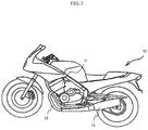
- FIG. 3 is a side view schematically showing a motorcycle 10 according to an embodiment of the present teaching.
- the motorcycle 10 corresponds to one example of the straddled vehicle of the present teaching.
- the motorcycle 10 includes a gasoline-fueled engine 11, an exhaust pipe 12, and a muffler 13.
- the exhaust pipe 12 is connected to an exhaust port of the engine 11.
- the muffler 13 is connected to the exhaust pipe 12.
- the exhaust gas purification system 1 (not shown) is provided in the exhaust pipe 12.
- a secondary air introducing device (not shown) for introducing a secondary air is also provided.
- the motorcycle 10 is configured to produce a mixed gas through injection.
- the present teaching is not limited to this example.
- the straddled vehicle of the present teaching may be of carburetor type.
- the straddled vehicle of the present teaching is not limited to the motorcycle 10.
- the straddled vehicle of the present teaching is not particularly limited, and examples thereof include motor tricycles, snowmobiles, ATVs (All-Terrain Vehicles), and the like.
- the exhaust gas purification system of the present teaching has good purification performance and a good peel resistance. Accordingly, the exhaust gas purification system of the present teaching is suitably used for a straddled vehicle, and can effectively reduce occurrence of peel-off of the catalyst due to vibrations, etc.
- ACZ is a cocatalyst containing 47.5 wt% of Al 2 O 3 , 23.25 wt% of CeO 2 , 23.25 wt% of ZrO 2 , 3.25 wt% of La 2 O 3 , and 2.75 wt% of Nd 2 O 3 . Then, the mixture was dried at 120°C for one hour, and then baked at 500°C for 80 min, to obtain Pt/ACZ serving as catalyst powder. The loading of Pt on the Pt/ACZ was 0.6 wt%. The average particle diameter (secondary particle diameter (D50)) of the composite powder was 16.8 ⁇ m.
- AZN is a cocatalyst containing 47.5 wt% of Al 2 O 3 , 42.5 wt% of ZrO 2 , 3.25 wt% of La 2 O 3 , and 6.75 wt% of Nd 2 O 3 . Then, the mixture was dried at 120°C for one hour, and then baked at 500°C for 80 min, to obtain Rh/AZN serving as catalyst powder. The loading of Rh on the Ph/AZN was 0.9 wt%. The average particle diameter (secondary particle diameter (D50)) of the composite powder was 14.8 ⁇ m.
- a stainless steel support 2 (the diameter 30 mm, the length 30 mm, the number of cells 300 cpsi) was prepared.
- the slurry for the high ceria content layer 5 was applied to the stainless steel support 2, and a resultant was dried at 120°C and baked at 450°C.
- the slurry for the low ceria content layer 6 was applied onto the high ceria content layer 5, and a resultant was dried at 120°C and baked at 450°C.
- an exhaust gas purification system according to Example 1 was obtained.
- the thickness of the high ceria content layer 5 was 10.5 ⁇ m.
- the thickness of the low ceria content layer 6 was 11.5 ⁇ m. Measurement of the thicknesses of the high ceria content layer 5 and the low ceria content layer 6 will be described later.
- Example 2 is different from Example 1 in the following conditions.
- the amount of the noble metal was changed, as shown in Table 2.
- the amount of water and the amount of nitric acid were adjusted such that the viscosity of the slurry for the low ceria content layer 6 can be higher than that of Example 1.
- the viscosity of the slurry for the low ceria content layer 6 was 500 cP.
- the viscosity of the slurry for the high ceria content layer 5 was 390 cP.
- a time period for milling the mixture with a ball mill was changed to 17 min. Except for these conditions, an exhaust gas purification system 1 was manufactured under the same conditions as of Example 1.
- Example 3 is different from Example 1 in the following conditions.
- the amount of the noble metal was changed, as shown in Table 2.
- the amount of water and the amount of nitric acid were adjusted such that the viscosity of the slurry for the low ceria content layer 6 can be higher than that of Example 1.
- the viscosity of the slurry for the low ceria content layer 6 was 600 cP.
- the viscosity of the slurry for the high ceria content layer 5 was 345 cP.
- a time period for milling the mixture with a ball mill was changed to 20 min. Except for these conditions, an exhaust gas purification system 1 was manufactured under the same conditions as of Example 1.
- Example 4 is different from Example 1 in the following conditions.
- the amount of the noble metal was changed, as shown in Table 2.
- the amount of water and the amount of nitric acid were adjusted such that the viscosity of the slurry for the high ceria content layer 5 and the viscosity of the slurry for the low ceria content layer 6 can be lower than that of Example 1.
- the viscosity of the slurry for the high ceria content layer 5 was 220 cP
- the viscosity of the slurry for the low ceria content layer was 150 cP.
- Example 5 is different from Example 1 in the conditions regarding ⁇ Production of catalyst powder for high ceria content layer 5>.
- the other conditions under which an exhaust gas purification system 1 was manufactured were the same as of Example 1.
- the viscosity of the slurry for the high ceria content layer 5 was 352 cP
- the viscosity of the slurry for the low ceria content layer 6 was 334 cP.
- Example 6 is different from Example 1 in the conditions regarding ⁇ Production of catalyst powder for high ceria content layer 5>.
- the other conditions under which an exhaust gas purification system 1 was manufactured were the same as of Example 1.
- the viscosity of the slurry for the high ceria content layer 5 was 367 cP
- the viscosity of the slurry for the low ceria content layer 6 was 334 cP.
- Example 7 is different from Example 1 in the conditions regarding ⁇ Production of catalyst powder for low ceria content layer 6>.
- the other conditions under which an exhaust gas purification system 1 was manufactured were the same as of Example 1.
- the viscosity of the slurry for the high ceria content layer 5 was 362 cP
- the viscosity of the slurry for the low ceria content layer 6 was 375 cP.
- Example 8 is different from Example 1 in the following conditions.
- the amount of the noble metal was changed, as shown in Table 2.
- the amount of water and the amount of nitric acid were adjusted such that the viscosity of the slurry for the high ceria content layer 5 and the viscosity of the slurry for the low ceria content layer 6 can be higher than that of Example 1.
- the viscosity of the slurry for the high ceria content layer 5 was 720 cP
- the viscosity of the slurry for the low ceria content layer 6 was 525 cP.
- Example 9 is different from Example 1 in the following conditions.
- the amount of the noble metal was changed, as shown in Table 2.
- the amount of water and the amount of nitric acid were adjusted such that the viscosity of the slurry for the high ceria content layer 5 and the viscosity of the slurry for the low ceria content layer 6 can be lower than that of Example 1.
- the viscosity of the slurry for the high ceria content layer 5 was 83 cP
- the viscosity of the slurry for the low ceria content layer 6 was 97 cP.
- Comparative Example 1 production of catalyst powder for the low ceria content layer 6 and preparation of a slurry for the low ceria content layer 6 were implemented by the same method as of Example 1.
- the slurry viscosity was 366 cP.
- the same stainless steel support 2 as that of Example 1 was prepared.
- the slurry for the low ceria content layer 6 was applied to the stainless steel support 2, and a resultant was dried at 120°C and baked at 450°C. In this manner, an exhaust gas purification system according to Comparative Example 1 was obtained.
- Comparative Example 2 production of catalyst powder for the high ceria content layer 5 and preparation of a slurry for the high ceria content layer 5 were implemented by the same method as of Example 1.
- the slurry viscosity was 378 cP.
- the same stainless steel support 2 as that of Example 1 was prepared.
- the slurry for the high ceria content layer 5 was applied to the stainless steel support 2, and a resultant was dried at 120°C and baked at 450°C. In this manner, an exhaust gas purification system according to Comparative Example 2 was obtained.
- Comparative Example 3 production of catalyst powder for the high ceria content layer 5 and catalyst powder for the low ceria content layer 6 and preparation of a slurry for the high ceria content layer 5 and a slurry for the low ceria content layer 6 were implemented by the same method as of Example 1.
- the viscosity of the slurry for the high ceria content layer 5 was 366 cP
- the viscosity of the slurry for the low ceria content layer 6 was 378 cP.
- the same stainless steel support 2 as that of Example 1 was prepared.
- the slurry for the low ceria content layer 6 was applied to the stainless steel support 2, and a resultant was dried at 120°C and baked at 450°C.
- FIGS. 4(a) to (c) are diagrams for explaining measurement of the thicknesses of the high ceria content layer and the low ceria content layer.
- FIG. 4(a) shows a cross-section as taken along the line A-A of FIG. 4(b).
- FIG. 4(b) is a transverse cross-sectional view showing the outer shape of the exhaust gas purification system 1.
- FIG. 4(c) shows a cross-section of a part of FIG. 4(b) on an enlarged scale, schematically illustrating cells 9 in the exhaust gas purification system 1.
- P represents a layer thickness measurement position.
- R represents the radius of the stainless steel support 2.
- L represents the length of the stainless steel support 2 with respect to the exhaust gas flow direction.
- layer thickness measurement positions P There are six layer thickness measurement positions P as shown in FIG. 4(b) .
- layer thicknesses at two locations are measured.
- layer thicknesses at twelve locations are measured.
- the six measurement positions P are dispersedly arranged in three regions with respect to the exhaust gas flow direction of the stainless steel support 2. Specifically, as shown in FIG. 4(b) , among the six measurement positions P, two measurement positions P are located in a middle portion of the stainless steel support 2 with respect to the exhaust gas flow direction of the stainless steel support 2, that is, located at a distance (1/2)L from an end surface 2a. Other two measurement positions P are located at a distance M from one end surface 2a of the stainless steel support 2. The remaining two measurement positions are located at a distance M from the other end surface 2a of the stainless steel support 2. The distance M is 5 mm.
- the measurement positions P are located at a distance (1/3)R from a center C and at a distance (2/3)R from the center with respect to the radial direction of the stainless steel support 2, as shown in FIG. 4(a) .
- Measured are the layer thickness of a catalyst provided on one surface of a circumferentially oriented portion 4a and the layer thickness of a catalyst provided on one surface of a radially oriented portion 4b of the stainless steel plate 4 that constitutes one cell 9 arranged in each of the six measurement positions P.
- the layer thickness is measured at a position where the catalyst is formed flatly.
- a catalyst adhered to a corner portion 9a of the cell 9 is relatively thick, but the layer thickness is not measured at the corner portion 9a.
- the layer thickness is obtained by: measuring the layer thickness of the circumferentially oriented portion 4a and the layer thickness of the radially oriented portion 4b in each of the six cells located in the six measurement positions P in total, namely, two positions ( FIG. 4(a) ) with respect to the radial direction in each of three regions ( FIG. 4(b) ) with respect to the exhaust gas flow direction; and calculating the average value.
- the layer thickness of each of the high ceria content layer 5 and the low ceria content layer 6 is measured after the high ceria content layer 5 and the low ceria content layer 6 are formed.
- the layer thickness of the high ceria content layer 5 is measured before the low ceria content layer 6 is formed; the total layer thickness of the high ceria content layer 5 and the low ceria content layer 6 is measured after the low ceria content layer 6 is formed; and the layer thickness of the high ceria content layer 5 is subtracted from the total layer thickness, to calculate the layer thickness of the low ceria content layer 6.
- a sample of each layer was prepared for the purpose of measuring the particle diameters of a ceria-zirconia portion and an alumina portion of a composite included in the layer.
- TEM transmission electron microscope
- the sample of each layer was observed, and an image of each layer was obtained. From each image, twenty ceria-zirconia portions and twenty alumina portions were arbitrarily extracted.
- the equivalent diameter of each ceria-zirconia portion was calculated and determined as the particle diameter of the ceria-zirconia portion.
- the longer diameter and shorter diameter of each alumina portion were measured and determined as the particle diameter of the alumina portion.
- the particle diameter of the ceria-zirconia portion was 4 to 5 nm.
- the shorter diameter was 3 to 10 nm and the longer diameter was 30 to 40 nm.
- each average particle diameter (equivalent diameter) was calculated, with the result that the average particle diameter of the ceria-zirconia portion was smaller than the average particle diameter of the alumina portion.
- each of the exhaust gas purification systems 1 manufactured in Examples 1 to 9 and Comparative Examples 1 to 3 was measured. Then, each of the exhaust gas purification systems 1 was subjected to an ultrasonic treatment for 10 min using an ultrasonic cleaner having ion-exchange water therein, then dried at 200°C for one hour using an electric furnace, then the mass was measured again, and the amount of peel-off was calculated based on the difference in mass before and after the ultrasonic treatment.
- a new exhaust gas purification system 1 and an exhaust gas purification system 1 heated in stoichiometric atmosphere at 800 °C for one hour were prepared, for the purpose of evaluating exhaust gas purification performance.
- a prepared catalyst was set in a reactor machine, and the temperature was raised from ambient temperature to 600 °C in a model gas simulating stoichiometric atmosphere, and held for 5 min after the temperature reached 600°C. Then, with a flow of a simulant gas having the composition shown in Table 1 below, purification performance was evaluated in a range of 150 to 600°C.
- the air-fuel ratio (AFR) of the simulant gas was varied within a range of approximately ⁇ 0.4.
- INJ(CO) and INJ(O 2 ) indicate CO and O 2 that were alternately introduced in order to vary the air-fuel ratio of the simulant gas.
- a peel resistance and purification performance are shown in Table 2.
- Lower Layer corresponds to the high ceria content layer 5
- Upper Layer corresponds to the low ceria content layer 6.
- Single Layer corresponds to the low ceria content layer.
- Single Layer corresponds to the high ceria content layer.
- Comparative Example 3 in the table, Lower Layer corresponds to the low ceria content layer, and Upper Layer corresponds to the high ceria content layer.
- the exhaust gas purification systems according to Examples 1 to 9 were able to achieve both a peel resistance and purification performance at a high level.
- the exhaust gas purification systems according to Examples 1 to 7 were able to achieve a good peel resistance with sufficient purification performance ensured.
- the exhaust gas purification systems according to Examples 1 to 7 were able to achieve both a peel resistance and purification performance at a further higher level.
- the exhaust gas purification system according to Comparative Example 1 was not able to provide sufficient purification performance (especially purification performance on NOx).
- the exhaust gas purification system according to Comparative Example 2 was neither able to provide a sufficient peel resistance nor sufficient purification performance (especially purification performance on NOx).
- the exhaust gas purification system according to Comparative Example 3 was not able to provide sufficient purification performance (especially purification performance on CO and HC). Thus, none of the exhaust gas purification systems according to Comparative Examples 1 to 3 were able to achieve both a peel resistance and purification performance at a high level.
Landscapes
- Chemical & Material Sciences (AREA)
- Engineering & Computer Science (AREA)
- Chemical Kinetics & Catalysis (AREA)
- Organic Chemistry (AREA)
- Materials Engineering (AREA)
- Health & Medical Sciences (AREA)
- Analytical Chemistry (AREA)
- General Chemical & Material Sciences (AREA)
- Oil, Petroleum & Natural Gas (AREA)
- Environmental & Geological Engineering (AREA)
- Biomedical Technology (AREA)
- Combustion & Propulsion (AREA)
- Catalysts (AREA)
- Exhaust Gas Treatment By Means Of Catalyst (AREA)
Abstract
Description
- The present teaching relates to an exhaust gas purification system and a straddled vehicle.
- Conventionally, a vehicle such as a straddled vehicle provided with a gasoline-fueled engine is widely used. An exhaust gas emitted from the engine contains harmful components including hydrocarbon (HC), carbon monoxide (CO), nitrogen oxide (NOx), etc. Thus, an exhaust gas purification system including a three-way catalyst that purifies and detoxifies the harmful components is conventionally used.
- The exhaust gas purification systems include an exhaust gas purification system provided with a metallic support. A catalyst layer including a three-way catalyst is provided on a surface of the metallic support. The coefficient of thermal expansion of the metallic support is different from the coefficient of thermal expansion of the catalyst layer. This raises a problem that the catalyst layer is likely to be peeled off from the metallic support if the exhaust gas purification system is subjected to a temperature change, vibrations, etc.
- Patent Literature 1 (PTL 1) discloses a method for manufacturing an exhaust gas purification catalyst. Used in the method is a slurry including a refractory alumina, a ceria-zirconia composite oxide, a binder, a viscosity modifier, and water. In the slurry, a solid content has an average particle diameter of 3 to 10 µm. The viscosity of the slurry is 300 to 2000 mPa·s. The slurry is applied directly onto a support made of a metal material, and is dried and baked. Then, a resulting baked product is immersed in a solution containing a noble metal catalyst component, and dried and baked.
Patent Literature 1 aims to improve a peel resistance and purification performance. - PTL 1: Japanese Patent Application Laid-Open No.
2010-89021 - It is desirable to achieve both a peel resistance and purification performance at a higher level. From this viewpoint, the technique disclosed in
Patent Literature 1 leaves room for improvement. - An object of the present teaching is to provide an exhaust gas purification system that is able to achieve both a peel resistance and purification performance at a higher level. Another object of the present teaching is to provide a straddled vehicle that is able to achieve both a peel resistance and purification performance of an exhaust gas purification system at a higher level even under severe vibratory conditions.
- The present teaching can adopt the following configurations.
- (1) An exhaust gas purification system of a gasoline-fueled engine, the exhaust gas purification system including:
- a stainless steel support made of stainless steel;
- a high ceria content layer containing ceria and at least one type of noble metal selected from the group consisting of Pt, Pd, Ir, Ru, and Os; and
- a low ceria content layer containing ceria and at least one type of noble metal selected from the group consisting of Rh, Ir, Ru, Pt, Pd, Au, Ag, and Os, the low ceria content layer having a ceria content lower than a ceria content in the high ceria content layer,
- the high ceria content layer being provided between the low ceria content layer and the stainless steel support so as to be in contact with the low ceria content layer and the stainless steel support.
The exhaust gas purification system of (1) is an exhaust gas purification system of a gasoline-fueled engine. In the exhaust gas purification system of (1), the high ceria content layer is provided between the low ceria content layer and the stainless steel support so as to be in contact with the low ceria content layer and the stainless steel support. This improves adhesiveness of the high ceria content layer and the low ceria content layer to the stainless steel support in the exhaust gas purification system of the gasoline-fueled engine. Occurrence of peel-off of the high ceria content layer and the low ceria content layer from the stainless steel support can be suppressed over a long term.
Since the high ceria content layer contains more ceria than the low ceria content layer does, an OSC (Oxygen Storage Capacity) function of the high ceria content layer is higher than an OSC function of the low ceria content layer. The OSC is an oxygen storage capacity. The high ceria content layer is less likely to be exposed to an exhaust gas than the low ceria content layer is. On the other hand, the low ceria content layer is more likely to be exposed to an exhaust gas than the high ceria content layer is.
In the configuration of (1), as described above, the low ceria content layer is likely to be exposed to the exhaust gas, but less likely to be influenced by the OSC function. The low ceria content layer contains at least one type of noble metal selected from the group consisting of Rh, Ir, Ru, Pt, Pd, Au, Ag, and Os. These noble metals have properties that promote a reduction reaction of NOx. The low ceria content layer, therefore, easily causes a reduction reaction of NOx. The reduction reaction is expressed by the following expression (A):
NOx+CO/HC→N2 +CO2 +H2O ... (A)
In the configuration of (1), as mentioned above, the high ceria content layer is less likely to be exposed to the exhaust gas, but has a high OSC function. The high ceria content layer contains at least one type of noble metal selected from the group consisting of Pt, Pd, Ir, Ru, and Os. These noble metals have properties that promote oxidation reactions of CO and HC. The high ceria content layer, therefore, can promote oxidation reactions of CO and HC. The oxidation reactions are expressed by the following expression (B):
CO/HC+O2 →CO2 +H2O ... (B)
Thus, the configuration of (1) can cause the oxidation reactions and the reduction reaction in a balanced manner.
As a result, both a peel resistance and purification performance of the exhaust gas purification system of the gasoline-fueled engine can be achieved at a high level. - (2) In the exhaust gas purification system of (1), it is preferable that
the noble metal in the high ceria content layer includes at least one type of metal of Pt and Pd.
Among Pt, Pd, Ir, Ru, and Os, Pt and Pd have better properties in respect of promotion of oxidation reactions of CO and HC. Accordingly, the configuration of (2) can achieve both a peel resistance and purification performance of the exhaust gas purification system of the gasoline-fueled engine at a higher level. - (3) In the exhaust gas purification system of (1) or (2), it is preferable that
the noble metal in the low ceria content layer includes at least one type of metal of Rh, Ir, and Ru.
Among Rh, Ir, Ru, Pt, Pd, Au, Ag, and Os, Rh, Ir, and Ru have better properties in respect of promotion of a reduction reaction of NOx. Accordingly, the configuration of (3) can achieve both a peel resistance and purification performance of the exhaust gas purification system of the gasoline-fueled engine at a higher level. - (4) In the exhaust gas purification system of any one of (1) to (3), it is preferable that
the percentage of ceria content in the high ceria content layer is 8 wt% or more and 40 wt% or less, and is higher than the percentage of ceria content in the low ceria content layer.
In the configuration of (4), the relationship between the OSC functions of the high ceria content layer and the low ceria content layer can be adjusted so as to further enhance purification performance of the exhaust gas purification system. - (5) In the exhaust gas purification system of any one of (1) to (4), it is preferable that
the percentage of ceria content in the low ceria content layer is less than 10 wt%, and is lower than the percentage of ceria content in the high ceria content layer.
In the configuration of (5), the relationship between the OSC functions of the high ceria content layer and the low ceria content layer can be adjusted so as to further enhance purification performance of the exhaust gas purification system. Here, the ceria content in the low ceria content layer may be 0 wt%. - (6) In the exhaust gas purification system of any one of (1) to (5), it is preferable that
the high ceria content layer having a thickness of 3 µm or more and 50 µm or less is provided between the low ceria content layer and the stainless steel support so as to be in contact with the low ceria content layer and the stainless steel support.
The configuration of (6) provides further improvement in the adhesiveness of the high ceria content layer and the low ceria content layer to the stainless steel support in the exhaust gas purification system of the gasoline-fueled engine. As a result, both a peel resistance and purification performance of the exhaust gas purification system of the gasoline-fueled engine can be achieved at a higher level. - (7) In the exhaust gas purification system of any one of (1) to (6), it is preferable that
the low ceria content layer having a thickness of 3 µm or more and 50 µm or less is provided on the high ceria content layer so as to be in contact with the high ceria content layer, the high ceria content layer being provided on the stainless steel support so as to be in contact with the stainless steel support.
The configuration of (7) provides further improvement in adhesiveness between the low ceria content layer and the high ceria content layer on the stainless steel support. As a result, both a peel resistance and purification performance of the exhaust gas purification system of the gasoline-fueled engine can be achieved at a higher level. - (8) In the exhaust gas purification system of any one of (1) to (7), it is preferable that
of the high ceria content layer and the low ceria content layer, at least the high ceria content layer contains a noble metal and a composite in which alumina and a ceria-zirconia solid solution doped with a rare earth element are combined.
The configuration of (8) can suppress sintering of the noble metal and aggregation of the ceria-zirconia solid solution. Further improvement in the purification performance can be obtained. As a result, both a peel resistance and purification performance of the exhaust gas purification system of the gasoline-fueled engine can be achieved at a higher level. In the configuration of (8), it is more preferable that both the high ceria content layer and the low ceria content layer contain a noble metal and a composite in which alumina and a ceria-zirconia solid solution doped with a rare earth element are combined. In a case where the ceria content in the low ceria content layer is 0 wt%, the ceria-zirconia solid solution contains no zirconia, but in the present teaching, such a solid solution is also called a ceria-zirconia solid solution. - (9) In the exhaust gas purification system of (8), it is preferable that
the composite has an alumina portion and a ceria-zirconia portion whose average particle diameter is smaller than the average particle diameter of the alumina portion.
In the configuration of (9), the composite (secondary particle) is formed such that the average particle diameters of the ceria-zirconia portion (primary particle) and the alumina portion (primary particle) of the composite can satisfy the relationship of (the average particle diameter of the alumina portion) > (the average particle diameter of the ceria-zirconia portion). The composite, which is formed such that the average particle diameter of the ceria-zirconia portion and the average particle diameter of the alumina portion can satisfy such a relationship, can be easily prepared so as to obtain properties and behaviors (e.g., the average particle diameter) suitable for adhesion to the stainless steel support, or is likely to have properties and behaviors suitable for adhesion to the stainless steel support. This makes it possible to improve adhesiveness between a catalyst layer and the stainless steel support in the exhaust gas purification system of the gasoline-fueled engine, and also to improve a heat resistance. Thus, occurrence of peel-off of the catalyst layer from the stainless steel support can be suppressed over a long term. As a result, both a peel resistance and purification performance of the exhaust gas purification system of the gasoline-fueled engine can be achieved at a high level. - (10) In the exhaust gas purification system of (8) or (9), it is preferable that
the composite has an average particle diameter of 6 µm or more and less than 10 µm.
The configuration of (10) can provide further improvement in adhesiveness of the high ceria content layer to the stainless steel support, and can also provide further improvement in adhesiveness between the high ceria content layer and the low ceria content layer. - (11) The exhaust gas purification system of any one of (1) to (10), in which
a surface of the high ceria content layer being in contact with the low ceria content layer is an uneven surface having unevenness, and the low ceria content layer is formed such that a component of the low ceria content layer is within a recess of the uneven surface of the high ceria content layer.
In the configuration of (11), the low ceria content layer is formed such that a component of the low ceria content layer is within the recess of the uneven surface of the high ceria content layer. This can increase adhesiveness of the low ceria content layer to the high ceria content layer due to anchor effects. This also can achieve tighter coupling of the low ceria content layer to the stainless steel support with interposition of the high ceria content layer. As a result, the adhesiveness of the low ceria content layer and the high ceria content layer to the stainless steel support is further improved. Accordingly, both a peel resistance and purification performance of the exhaust gas purification system of the gasoline-fueled engine can be achieved at a higher level. - (12) A straddled vehicle including the exhaust gas purification system of any one of (1) to (11).
- The straddled vehicle of (12) can achieve both a peel resistance and purification performance of the exhaust gas purification system at a higher level even under severe vibratory conditions.
- The present teaching can achieve both a peel resistance and purification performance at a higher level.
-
- [
FIG. 1 ] (a) is a front elevational view schematically showing an exhaust gas purification system according to an embodiment of the present teaching; and (b) is a cross-sectional view schematically showing a stainless steel support, a high ceria content layer, and a low ceria content layer of the exhaust gas purification system shown in (a). - [
FIG. 2 ] (a) is an electron micrograph showing a cross-section of a stainless steel support, a high ceria content layer, and a low ceria content layer in one example; and (b) schematically shows a composite serving as catalyst particles. - [
FIG. 3 ] A side view schematically showing a motorcycle according to an embodiment of the present teaching. - [
FIG. 4 ] (a) to (c) are diagrams for explaining measurement of film thicknesses of the high ceria content layer and the low ceria content layer. -
FIG. 1(a) is a front elevational view schematically showing an exhaustgas purification system 1 according to an embodiment of the present teaching. The exhaustgas purification system 1 of this embodiment includes astainless steel support 2. Thestainless steel support 2 includes a stainless steelcylindrical body 3 and astainless steel plate 4. The type of stainless steel is not particularly limited. For example, 20Cr-5Al based stainless steel is suitably adopted as the stainless steel. - The stainless steel
cylindrical body 3 has a cylindrical shape pierced in an exhaust gas flow direction. The shape of the stainless steelcylindrical body 3 is not particularly limited. It suffices that the stainless steelcylindrical body 3 is configured so as to ensure a path in the exhaust gas flow direction. Thestainless steel plate 4 is bent into a wave-like shape. Thestainless steel plate 4, which is wound about an axis parallel to the exhaust gas flow direction, is arranged in the stainless steelcylindrical body 3. Thestainless steel plate 4 is fixed in the stainless steelcylindrical body 3. Thus, thestainless steel support 2 has a honeycomb structure. In the drawings, a structure for fixing thestainless steel plate 4 is not shown. As the fixing structure, a conventionally known fixing structure is adoptable. A structure of thestainless steel support 2 is not limited to the honeycomb structure. Instead of thestainless steel plate 4, for example, a stainless steel wire may be loaded in the stainless steelcylindrical body 3. A highceria content layer 5 and a lowceria content layer 6 are formed on the stainless steel support 2 (stainless steel plate 4), as will be described later. Ceria is an oxide (CeO2) of Ce(IV). -
FIG. 1(b) is a cross-sectional view schematically showing a stainless steel support, a high ceria content layer, and a low ceria content layer of the exhaust gas purification system shown inFIG. 1(a) . - The high
ceria content layer 5 is formed on thestainless steel plate 4 which constitutes thestainless steel support 2. The thickness of the highceria content layer 5 is, though not particularly limited, preferably 3 µm or more and 50 µm or less from the viewpoint of achievement of both a peel resistance and purification performance. The highceria content layer 5 is in contact with thestainless steel plate 4. The lowceria content layer 6 is formed on the highceria content layer 5. The thickness of the lowceria content layer 6 is, though not particularly limited, preferably 3 µm or more and 50 µm or less from the viewpoint of achievement of both a peel resistance and purification performance. The lowceria content layer 6 is in contact with the highceria content layer 5. That is, the highceria content layer 5 is provided between the lowceria content layer 6 and thestainless steel plate 4 so as to be in contact with the lowceria content layer 6 and thestainless steel plate 4. No other layer is provided on the lowceria content layer 6, and the lowceria content layer 6 is exposed. That is, the lowceria content layer 6 is provided so as to be directly contactable with an exhaust gas. The highceria content layer 5, on the other hand, is provided so as to be contactable with the exhaust gas having passed through the lowceria content layer 6. - The high
ceria content layer 5 includes ceria and a noble metal. As for the ceria, the highceria content layer 5 includes a composite containing ceria. In the composite, alumina (Al2O3) and a ceria-zirconia (CeO2·ZrO2) solid solution doped with a rare earth element are combined. In the composite, the average particle diameter of a ceria-zirconia portion is smaller than the average particle diameter of an alumina portion. A ceria content (wt%) in the highceria content layer 5 is higher than a ceria content (wt%) in the lowceria content layer 6. The ceria content in the highceria content layer 5 is preferably 8 wt% or more and 40 wt% or less. This is because better purification performance can be achieved. As for the noble metal, the highceria content layer 5 includes Pt. - As the noble metal included in the high
ceria content layer 5, at least one type of noble metal selected from the group consisting of Pt, Pd, Ir, Ru, and Os can be mentioned. These noble metals have properties that promote oxidation reactions of CO and HC. It is preferable that the noble metal included in the highceria content layer 5 includes at least one type of metal of Pt or Pd. This is because these noble metals have better performance in promoting oxidation reactions. The highceria content layer 5 may contain Rh in addition to at least one type of metal, of Pt or Pd. A noble metal content in the highceria content layer 5 is not particularly limited, and can be set appropriately. The average particle diameter of the noble metal is smaller than the average particle diameter of the ceria-zirconia portion, for example. In the highceria content layer 5, the rare earth element doped in the ceria-zirconia solid solution is not particularly limited. Preferably, the rare earth element doped in the ceria-zirconia solid solution includes at least one type of element selected from La, Nd, Pr, and Y. - The low
ceria content layer 6 includes ceria and a noble metal. As for the ceria, the lowceria content layer 6 includes a composite containing ceria. In the composite, alumina and a ceria-zirconia solid solution doped with a rare earth element are combined. In the composite, the average particle diameter of a ceria-zirconia portion is smaller than the average particle diameter of an alumina portion. A ceria content (wt%) in the lowceria content layer 6 is lower than a ceria content (wt%) in the highceria content layer 5. The ceria content in the lowceria content layer 6 is preferably 0 wt% or more and less than 10 wt%. This is because better purification performance can be achieved. As for the noble metal, the lowceria content layer 6 includes Rh. The ceria content in the lowceria content layer 6 is to such a degree that, for example, a reduction reaction of NOx by the noble metal (e.g., Rh) is not hindered. - As the noble metal included in the low
ceria content layer 6, at least one type of noble metal selected from the group consisting of Rh, Ir, Ru, Pt, Pd, Au, Ag, and Os can be mentioned. These noble metals have properties that promote a reduction reaction of NOx. From the viewpoint of performance in promoting a reduction reaction, it is preferable that the noble metal included in the lowceria content layer 6 includes at least one type of noble metal selected from the group consisting of Rh, Ir, and Ru. It is more preferable that the noble metal included in the lowceria content layer 6 is Rh. A noble metal content in the lowceria content layer 6 is not particularly limited, and can be set appropriately. The average particle diameter of the noble metal is smaller than the average particle diameter of the ceria-zirconia portion, for example. An element adoptable as the rare earth element doped in the ceria-zirconia solid solution of the lowceria content layer 6 can be the same as that of the rare earth element doped in the ceria-zirconia solid solution of the highceria content layer 5. - In the schematic illustration in
FIG. 1 , a boundary surface between the highceria content layer 5 and the lowceria content layer 6 is flat. One exemplary embodiment of the boundary surface between the highceria content layer 5 and the lowceria content layer 6 may be the one shown inFIG. 2(a) , for example. -
FIG. 2(a) is an electron micrograph showing a cross-section of a stainless steel support, a high ceria content layer, and a low ceria content layer in one example. A surface of the highceria content layer 5 in contact with the lowceria content layer 6 is anuneven surface 5a having unevenness. Theuneven surface 5a hasrecesses 5b recessed toward thestainless steel plate 4 side. The lowceria content layer 6 is formed such that components of the lowceria content layer 6 are within therecesses 5b of theuneven surface 5a of the highceria content layer 5. At least some of therecesses 5b of theuneven surface 5a have a depth of, for example, not less than 1/2 of the thickness of the highceria content layer 5. -
FIG. 2(b) schematically shows a composite 7. In the composite 7, alumina and a ceria-zirconia solid solution doped with a rare earth element are combined. The composite 7 has analumina portion 7a and a ceria-zirconia portion 7b. The noble metal particles 8 are supported on the composite 7. The composite 7 having the noble metal particles 8 supported thereon constitutes each part of the highceria content layer 5 and the lowceria content layer 6. - In this embodiment, the average particle diameter of the ceria-
zirconia portion 7b (primary particle) is smaller than the average particle diameter of thealumina portion 7a (primary particle). It is preferable that the average particle diameter (D50) of the composite 7 (secondary particle) is 6 µm or more and less than 10 µm. The average particle diameter of the ceria-zirconia portion (primary particle) is measured in the following manner. Based on the surface area of a primary particle in an image or photograph of the high ceria content layer or the low ceria content layer, the diameter (equivalent diameter) of the primary particle is calculated assuming that the primary particle in the image or photograph is a perfect circle. Based on the number (frequency) and the diameters of the obtained primary particles, the average particle diameter of the primary particle diameters is calculated. As for the alumina portion (primary particle) whose shape is normally like an elongated rectangle, the longer diameter (length in the longitudinal direction) and the shorter diameter (length in the short-side direction) of an alumina portion included in the image or photograph are measured. The average particle diameter (D50) of the secondary particles is measured using a particle counter. - The exhaust
gas purification system 1 according to this embodiment is manufactured, for example, as follows. Thestainless steel support 2 is prepared. A slurry for forming the highceria content layer 5 and a slurry for forming the lowceria content layer 6 are respectively prepared. The preparation of the slurries is implemented by, for example, mixing alumina-ceria-zirconia composite powder, alumina, and a binder into a solvent (e.g., water) and then agitating. Here, the alumina-ceria-zirconia composite powder is powder obtained by combining alumina with a ceria-zirconia solid solution. The alumina-ceria-zirconia composite powder before forming the slurry has an average particle diameter (secondary particle diameter (D50)) of, for example, 1 µm or more and 100 µm or less. The alumina-ceria-zirconia composite powder has noble metal particles adsorbed thereon. The ceria-zirconia solid solution is doped with a rare earth element. Then, a milling process is performed to adjust the particle size of each of the obtained slurries. It is preferable that the milling process is performed such that the average particle diameter of the composite obtained after milling can be adjusted to 6 µm or more and less than 10 µm. In this manner, the slurry for forming the highceria content layer 5 and the slurry for forming the lowceria content layer 6 are obtained. Then, the slurry for forming the highceria content layer 5 is applied to thestainless steel support 2. Thestainless steel support 2 having the slurry applied thereon is dried and baked. To the resulting baked product, the slurry for forming the lowceria content layer 6 is applied. The baked product having the slurry applied thereon is dried and baked. As a result, the exhaustgas purification system 1 including thestainless steel support 2 with the highceria content layer 5 and the lowceria content layer 6 formed thereon can be manufactured. Separately from the correlation between the slurry viscosity and the adhesiveness of therespective layers stainless steel support 2, there is a high correlation between the average particle diameter of a solid content (e.g., the composite) and the adhesiveness of therespective layers stainless steel support 2. This embodiment can achieve both a peel resistance and purification performance at a higher level depending on a combination of such a high correlation and a composition of therespective layers stainless steel support 2. The slurry viscosity is not particularly limited, as long as the viscosity is to such a degree that therespective layers stainless steel support 2. The slurry viscosity can be selected as appropriate so as to allow therespective layers stainless steel support 2. -
FIG. 3 is a side view schematically showing amotorcycle 10 according to an embodiment of the present teaching. - The
motorcycle 10 corresponds to one example of the straddled vehicle of the present teaching. Themotorcycle 10 includes a gasoline-fueledengine 11, anexhaust pipe 12, and amuffler 13. Theexhaust pipe 12 is connected to an exhaust port of theengine 11. Themuffler 13 is connected to theexhaust pipe 12. In theexhaust pipe 12, the exhaust gas purification system 1 (not shown) is provided. In theexhaust pipe 12, a secondary air introducing device (not shown) for introducing a secondary air is also provided. Themotorcycle 10 is configured to produce a mixed gas through injection. The present teaching is not limited to this example. The straddled vehicle of the present teaching may be of carburetor type. - The straddled vehicle of the present teaching is not limited to the
motorcycle 10. The straddled vehicle of the present teaching is not particularly limited, and examples thereof include motor tricycles, snowmobiles, ATVs (All-Terrain Vehicles), and the like. The exhaust gas purification system of the present teaching has good purification performance and a good peel resistance. Accordingly, the exhaust gas purification system of the present teaching is suitably used for a straddled vehicle, and can effectively reduce occurrence of peel-off of the catalyst due to vibrations, etc. - A prototype of the exhaust gas purification system according to this embodiment was manufactured and effects thereof were examined, a result of which will be described below.
- 0.3L of a dinitrodiamine platinum nitrate solution (Pt=30g) and 4.97kg of ACZ were added to 15L of ion-exchange water, and agitation was performed at 80°C for one hour, to obtain a mixture. Here, ACZ is a cocatalyst containing 47.5 wt% of Al2 O3, 23.25 wt% of CeO2, 23.25 wt% of ZrO2, 3.25 wt% of La2O3, and 2.75 wt% of Nd2O3. Then, the mixture was dried at 120°C for one hour, and then baked at 500°C for 80 min, to obtain Pt/ACZ serving as catalyst powder. The loading of Pt on the Pt/ACZ was 0.6 wt%. The average particle diameter (secondary particle diameter (D50)) of the composite powder was 16.8 µm.
- To 4800g of the obtained Pt/ACZ, 1805g of γ-Al2O3 (Al2O3:La2O3 (weight ratio)), 602g of a CeO2 sol (nitrate solution containing 30 wt% of CeO2) (CeO2=180.6g), 192mL of nitric acid (1.38), and 7000g of ion-exchange water were added, to prepare a mixture. The mixture was subjected to a milling process. To be specific, the mixture was milled for 15 min with a ball mill. As a result, a slurry for the high
ceria content layer 5 was obtained. After the milling, the composite had an average particle diameter of 8.6 µm. The slurry for the highceria content layer 5 had a viscosity of 362 cP. - 0.45L of a rhodium nitrate solution (Rh=45g) and 4.955kg of AZN were added to 15L of ion-exchange water, and agitation was performed at 80°C for one hour, to obtain a mixture. Here, AZN is a cocatalyst containing 47.5 wt% of Al2O3, 42.5 wt% of ZrO2, 3.25 wt% of La2O3, and 6.75 wt% of Nd2O3. Then, the mixture was dried at 120°C for one hour, and then baked at 500°C for 80 min, to obtain Rh/AZN serving as catalyst powder. The loading of Rh on the Ph/AZN was 0.9 wt%. The average particle diameter (secondary particle diameter (D50)) of the composite powder was 14.8 µm.
- To 4800g of the obtained Rh/AZN, 1805g of γ-Al2O3 (Al2O3:La2O3 (weight ratio)), 602g of a CeO2 sol (nitrate solution containing 30 wt% of CeO2) (CeO2=180.6g), 192mL of nitric acid (1.38), and 7000g of ion-exchange water were added, to prepare a mixture. The mixture was subjected to a milling process. To be specific, the mixture was milled for 15 min with a ball mill. As a result, a slurry for the low
ceria content layer 6 was obtained. After the milling, the composite had an average particle diameter of 8.6 µm. The slurry for the lowceria content layer 6 had a viscosity of 368 cP. - A stainless steel support 2 (the diameter 30 mm, the length 30 mm, the number of cells 300 cpsi) was prepared. The slurry for the high
ceria content layer 5 was applied to thestainless steel support 2, and a resultant was dried at 120°C and baked at 450°C. Then, the slurry for the lowceria content layer 6 was applied onto the highceria content layer 5, and a resultant was dried at 120°C and baked at 450°C. In this manner, an exhaust gas purification system according to Example 1 was obtained. The thickness of the highceria content layer 5 was 10.5 µm. The thickness of the lowceria content layer 6 was 11.5 µm. Measurement of the thicknesses of the highceria content layer 5 and the lowceria content layer 6 will be described later. - Example 2 is different from Example 1 in the following conditions. The amount of the noble metal was changed, as shown in Table 2. In addition, the amount of water and the amount of nitric acid were adjusted such that the viscosity of the slurry for the low
ceria content layer 6 can be higher than that of Example 1. As a result, the viscosity of the slurry for the lowceria content layer 6 was 500 cP. The viscosity of the slurry for the highceria content layer 5 was 390 cP. Moreover, in the preparation of the slurry for the highceria content layer 5 and the preparation of the slurry for the lowceria content layer 6, a time period for milling the mixture with a ball mill was changed to 17 min. Except for these conditions, an exhaustgas purification system 1 was manufactured under the same conditions as of Example 1. - Example 3 is different from Example 1 in the following conditions. The amount of the noble metal was changed, as shown in Table 2. In addition, the amount of water and the amount of nitric acid were adjusted such that the viscosity of the slurry for the low
ceria content layer 6 can be higher than that of Example 1. As a result, the viscosity of the slurry for the lowceria content layer 6 was 600 cP. The viscosity of the slurry for the highceria content layer 5 was 345 cP. Moreover, in the preparation of the slurry for the highceria content layer 5 and the preparation of the slurry for the lowceria content layer 6, a time period for milling the mixture with a ball mill was changed to 20 min. Except for these conditions, an exhaustgas purification system 1 was manufactured under the same conditions as of Example 1. - Example 4 is different from Example 1 in the following conditions. The amount of the noble metal was changed, as shown in Table 2. In addition, the amount of water and the amount of nitric acid were adjusted such that the viscosity of the slurry for the high
ceria content layer 5 and the viscosity of the slurry for the lowceria content layer 6 can be lower than that of Example 1. As a result, the viscosity of the slurry for the highceria content layer 5 was 220 cP, and the viscosity of the slurry for the low ceria content layer was 150 cP. Moreover, in the preparation of the slurry for the highceria content layer 5 and the preparation of the slurry for the lowceria content layer 6, a time period for milling the mixture with a ball mill was changed to 30 min. Except for these conditions, an exhaustgas purification system 1 was manufactured under the same conditions as of Example 1. - Example 5 is different from Example 1 in the conditions regarding <Production of catalyst powder for high
ceria content layer 5>. In Example 5, 0.3L of a dinitrodiamine platinum nitrate solution (Pt=30g) and 4.97kg of ACZ were added to 15L of ion-exchange water, and agitation was performed at 80°C for one hour, to obtain a mixture. Then, the mixture was dried at 120°C for one hour, and then baked at 500°C for 80 min, to obtain Pt/ACZ serving as a catalyst powder. The other conditions under which an exhaustgas purification system 1 was manufactured were the same as of Example 1. The viscosity of the slurry for the highceria content layer 5 was 352 cP, and the viscosity of the slurry for the lowceria content layer 6 was 334 cP. - Example 6 is different from Example 1 in the conditions regarding <Production of catalyst powder for high
ceria content layer 5>. In Example 6, 0.3L of a dinitrodiamine platinum nitrate solution (Pt=30g) and 4.97kg of ACZ were added to 15L of ion-exchange water, and agitation was performed at 80°C for one hour, to obtain a mixture. Then, the mixture was dried at 120°C for one hour, and then baked at 500°C for 80 min, to obtain Pt/ACZ serving as a catalyst powder. The other conditions under which an exhaustgas purification system 1 was manufactured were the same as of Example 1. The viscosity of the slurry for the highceria content layer 5 was 367 cP, and the viscosity of the slurry for the lowceria content layer 6 was 334 cP. - Example 7 is different from Example 1 in the conditions regarding <Production of catalyst powder for low
ceria content layer 6>. In Example 7, 0.45L of a rhodium nitrate solution (Rh=45g) and 4.955kg of ACZ were added to 15L of ion-exchange water, and agitation was performed at 80°C for one hour, to obtain a mixture. Then, the mixture was dried at 120°C for one hour, and then baked at 500°C for 80 min, to obtain Rh/ACZ serving as a catalyst powder. The other conditions under which an exhaustgas purification system 1 was manufactured were the same as of Example 1. The viscosity of the slurry for the highceria content layer 5 was 362 cP, and the viscosity of the slurry for the lowceria content layer 6 was 375 cP. - Example 8 is different from Example 1 in the following conditions. The amount of the noble metal was changed, as shown in Table 2. In addition, the amount of water and the amount of nitric acid were adjusted such that the viscosity of the slurry for the high
ceria content layer 5 and the viscosity of the slurry for the lowceria content layer 6 can be higher than that of Example 1. As a result, the viscosity of the slurry for the highceria content layer 5 was 720 cP, and the viscosity of the slurry for the lowceria content layer 6 was 525 cP. Moreover, in the preparation of the slurry for the highceria content layer 5 and the preparation of the slurry for the lowceria content layer 6, a time period for milling the mixture with a ball mill was changed to 10 min. Except for these conditions, an exhaustgas purification system 1 was manufactured under the same conditions as of Example 1. - Example 9 is different from Example 1 in the following conditions. The amount of the noble metal was changed, as shown in Table 2. In addition, the amount of water and the amount of nitric acid were adjusted such that the viscosity of the slurry for the high
ceria content layer 5 and the viscosity of the slurry for the lowceria content layer 6 can be lower than that of Example 1. As a result, the viscosity of the slurry for the highceria content layer 5 was 83 cP, and the viscosity of the slurry for the lowceria content layer 6 was 97 cP. Moreover, in the preparation of the slurry for the highceria content layer 5 and the preparation of the slurry for the lowceria content layer 6, a time period for milling the mixture with a ball mill was changed to 40 min. Except for these conditions, an exhaustgas purification system 1 was manufactured under the same conditions as of Example 1. - In Comparative Example 1, production of catalyst powder for the low
ceria content layer 6 and preparation of a slurry for the lowceria content layer 6 were implemented by the same method as of Example 1. The slurry viscosity was 366 cP. Then, the samestainless steel support 2 as that of Example 1 was prepared. The slurry for the lowceria content layer 6 was applied to thestainless steel support 2, and a resultant was dried at 120°C and baked at 450°C. In this manner, an exhaust gas purification system according to Comparative Example 1 was obtained. - In Comparative Example 2, production of catalyst powder for the high
ceria content layer 5 and preparation of a slurry for the highceria content layer 5 were implemented by the same method as of Example 1. The slurry viscosity was 378 cP. Then, the samestainless steel support 2 as that of Example 1 was prepared. The slurry for the highceria content layer 5 was applied to thestainless steel support 2, and a resultant was dried at 120°C and baked at 450°C. In this manner, an exhaust gas purification system according to Comparative Example 2 was obtained. - In Comparative Example 3, production of catalyst powder for the high
ceria content layer 5 and catalyst powder for the lowceria content layer 6 and preparation of a slurry for the highceria content layer 5 and a slurry for the lowceria content layer 6 were implemented by the same method as of Example 1. The viscosity of the slurry for the highceria content layer 5 was 366 cP, and the viscosity of the slurry for the lowceria content layer 6 was 378 cP. Then, the samestainless steel support 2 as that of Example 1 was prepared. The slurry for the lowceria content layer 6 was applied to thestainless steel support 2, and a resultant was dried at 120°C and baked at 450°C. Then, the slurry for the highceria content layer 5 was applied onto the lowceria content layer 6, and a resultant was dried at 120°C and baked at 450°C. In this manner, an exhaust gas purification system according to Comparative Example 3 was obtained. - For each of the exhaust gas purification systems according to Examples 1 to 9 and Comparative Examples 1 to 3, the thicknesses of the high ceria content layer and the low ceria content layer were measured.
FIGS. 4(a) to (c) are diagrams for explaining measurement of the thicknesses of the high ceria content layer and the low ceria content layer.FIG. 4(a) shows a cross-section as taken along the line A-A ofFIG. 4(b). FIG. 4(b) is a transverse cross-sectional view showing the outer shape of the exhaustgas purification system 1.FIG. 4(c) shows a cross-section of a part ofFIG. 4(b) on an enlarged scale, schematically illustratingcells 9 in the exhaustgas purification system 1. InFIG. 4(a) and FIG. 4(b) , P represents a layer thickness measurement position. R represents the radius of thestainless steel support 2. L represents the length of thestainless steel support 2 with respect to the exhaust gas flow direction. - There are six layer thickness measurement positions P as shown in
FIG. 4(b) . For onecell 9 arranged in each measurement position P, layer thicknesses at two locations are measured. Thus, for each exhaust gas purification system, layer thicknesses at twelve locations are measured. - As shown in
FIG. 4(b) , the six measurement positions P are dispersedly arranged in three regions with respect to the exhaust gas flow direction of thestainless steel support 2. Specifically, as shown inFIG. 4(b) , among the six measurement positions P, two measurement positions P are located in a middle portion of thestainless steel support 2 with respect to the exhaust gas flow direction of thestainless steel support 2, that is, located at a distance (1/2)L from anend surface 2a. Other two measurement positions P are located at a distance M from oneend surface 2a of thestainless steel support 2. The remaining two measurement positions are located at a distance M from theother end surface 2a of thestainless steel support 2. The distance M is 5 mm. When thestainless steel support 2 is viewed in the exhaust gas flow direction, the measurement positions P are located at a distance (1/3)R from a center C and at a distance (2/3)R from the center with respect to the radial direction of thestainless steel support 2, as shown inFIG. 4(a) . - Measured are the layer thickness of a catalyst provided on one surface of a circumferentially oriented
portion 4a and the layer thickness of a catalyst provided on one surface of a radially oriented portion 4b of thestainless steel plate 4 that constitutes onecell 9 arranged in each of the six measurement positions P. The layer thickness is measured at a position where the catalyst is formed flatly. A catalyst adhered to acorner portion 9a of thecell 9 is relatively thick, but the layer thickness is not measured at thecorner portion 9a. - As thus described above, the layer thickness is obtained by: measuring the layer thickness of the circumferentially oriented
portion 4a and the layer thickness of the radially oriented portion 4b in each of the six cells located in the six measurement positions P in total, namely, two positions (FIG. 4(a) ) with respect to the radial direction in each of three regions (FIG. 4(b) ) with respect to the exhaust gas flow direction; and calculating the average value. Here, it may be acceptable that the layer thickness of each of the highceria content layer 5 and the lowceria content layer 6 is measured after the highceria content layer 5 and the lowceria content layer 6 are formed. It may also be acceptable that: the layer thickness of the highceria content layer 5 is measured before the lowceria content layer 6 is formed; the total layer thickness of the highceria content layer 5 and the lowceria content layer 6 is measured after the lowceria content layer 6 is formed; and the layer thickness of the highceria content layer 5 is subtracted from the total layer thickness, to calculate the layer thickness of the lowceria content layer 6. - For each of the exhaust
gas purification systems 1 according to Examples 1 to 9 and Comparative Examples 1 to 3, a sample of each layer was prepared for the purpose of measuring the particle diameters of a ceria-zirconia portion and an alumina portion of a composite included in the layer. Using a transmission electron microscope (TEM), the sample of each layer was observed, and an image of each layer was obtained. From each image, twenty ceria-zirconia portions and twenty alumina portions were arbitrarily extracted. As for the ceria-zirconia portions, as described above, the equivalent diameter of each ceria-zirconia portion was calculated and determined as the particle diameter of the ceria-zirconia portion. As for the alumina portions, the longer diameter and shorter diameter of each alumina portion were measured and determined as the particle diameter of the alumina portion. As a result, in any of the exhaustgas purification systems 1 according to Examples 1 to 9 and Comparative Examples 1 to 3, the particle diameter of the ceria-zirconia portion was 4 to 5 nm. As for the particle diameter of the alumina portion, the shorter diameter was 3 to 10 nm and the longer diameter was 30 to 40 nm. Furthermore, each average particle diameter (equivalent diameter) was calculated, with the result that the average particle diameter of the ceria-zirconia portion was smaller than the average particle diameter of the alumina portion. - The mass of each of the exhaust
gas purification systems 1 manufactured in Examples 1 to 9 and Comparative Examples 1 to 3 was measured. Then, each of the exhaustgas purification systems 1 was subjected to an ultrasonic treatment for 10 min using an ultrasonic cleaner having ion-exchange water therein, then dried at 200°C for one hour using an electric furnace, then the mass was measured again, and the amount of peel-off was calculated based on the difference in mass before and after the ultrasonic treatment. - For each of the exhaust
gas purification systems 1 manufactured in Examples 1 to 9 and Comparative Examples 1 to 3, a new exhaustgas purification system 1 and an exhaustgas purification system 1 heated in stoichiometric atmosphere at 800 °C for one hour were prepared, for the purpose of evaluating exhaust gas purification performance. A prepared catalyst was set in a reactor machine, and the temperature was raised from ambient temperature to 600 °C in a model gas simulating stoichiometric atmosphere, and held for 5 min after the temperature reached 600°C. Then, with a flow of a simulant gas having the composition shown in Table 1 below, purification performance was evaluated in a range of 150 to 600°C. During the evaluation of purification performance, the air-fuel ratio (AFR) of the simulant gas was varied within a range of approximately ±0.4. In Table 1, INJ(CO) and INJ(O2) indicate CO and O2 that were alternately introduced in order to vary the air-fuel ratio of the simulant gas. - A peel resistance and purification performance are shown in Table 2. As for Examples 1 to 9, in the table, Lower Layer corresponds to the high
ceria content layer 5, and Upper Layer corresponds to the lowceria content layer 6. As for Comparative Example 1, Single Layer corresponds to the low ceria content layer. As for Comparative Example 2, Single Layer corresponds to the high ceria content layer. As for Comparative Example 3, in the table, Lower Layer corresponds to the low ceria content layer, and Upper Layer corresponds to the high ceria content layer.[Table 1] Gaseous Species C3H6 ppm 2400 C3H8 ppm 600 CO % 0.5 NO ppm 800 NH3 ppm 0 O2 % 0.67 CO2 % 10 H2O % 10 H2 % 0.2 INJ(CO) % 0.8 INJ(O2) % 0.4 [Table 2] Noble Metal Amount of Noble Metal Ceria Content Average Particle Diameter of Com posite Film Thickness Total Film Thickness Peel Resistance Purification Perform ance Amount of Peel-off CO HC Nox - g/L wt% µm µm µm % % % % Ex1 Upper Layer Rh 0.3 2.7 8.6 11.5 22.0 3.9 93.5 80.9 80.0 Low er Layer Pt 0.3 19.1 8.6 10.5 Ex2 Uppe rLayer Rh 0.1 2.7 8.0 18.5 31.0 8.3 93.1 79.9 79.7 Low er Layer Pt 0.3 19.1 8.7 12.5 Ex3 Upper Layer Rh 0.1 2.7 7.6 12.7 23.7 6.7 93.1 79.5 79.7 Lower Layer Pt 0.3 19.1 7.4 11 Ex4 Upper Layer Rh 0.1 2.7 6.3 8.7 17.0 7.5 93.1 79.5 79.6 Low er Layer Pt 0.3 19.1 6.2 8.3 Ex5 Upper Layer Rh 0.3 2.7 8.6 13.7 24.3 5.4 93.5 81.0 76.4 Low er Layer Pt 0.3 9.8 8.2 10.6 Ex6 Upper Layer Rh 0.3 2.7 8.6 11.4 20.2 6.2 93.8 81.3 79.6 Lower Layer Pt 0.3 31.0 8.4 8.8 Ex7 U pper Layer Rh 0.3 9.8 8.8 14.4 25.7 7.6 90.2 77.0 77.1 Low er Layer Pt 0.3 19.1 8.6 11.3 Ex8 Upper Layer Rh 0.1 2.7 11.6 18.8 30.7 11.8 93.2 80.2 80.1 Low er Layer Pt 0.3 19.1 13.3 11.9 Ex9 Upper Layer Rh 0.1 2.7 5.9 5.4 10.0 10.9 92.2 77.3 79.2 Low er Layer Pt 0.3 19.1 5.5 4.6 Com Ex1 Single Layer Rh 0.3 2.7 8.8 10.1 10.1 8.0 90.3 80.9 64.6 Com Ex2 Single Layer Pt 0.3 19.1 8.3 11.6 11.6 19.0 98.3 80.8 61.0 Com Ex3 Upper Layer Pt 0.3 19.1 8.3 12.2 23.4 7.7 85.3 72.6 77.4 Low er Layer Rh 0.3 2.7 8.8 11.2 - As shown in Table 2, the exhaust gas purification systems according to Examples 1 to 9 were able to achieve both a peel resistance and purification performance at a high level. In particular, the exhaust gas purification systems according to Examples 1 to 7 were able to achieve a good peel resistance with sufficient purification performance ensured. As a result, the exhaust gas purification systems according to Examples 1 to 7 were able to achieve both a peel resistance and purification performance at a further higher level.
- The exhaust gas purification system according to Comparative Example 1, on the other hand, was not able to provide sufficient purification performance (especially purification performance on NOx). The exhaust gas purification system according to Comparative Example 2 was neither able to provide a sufficient peel resistance nor sufficient purification performance (especially purification performance on NOx). The exhaust gas purification system according to Comparative Example 3 was not able to provide sufficient purification performance (especially purification performance on CO and HC). Thus, none of the exhaust gas purification systems according to Comparative Examples 1 to 3 were able to achieve both a peel resistance and purification performance at a high level.
- The embodiments and variations can be combined as appropriate. It should be understood that the terms and expressions used herein are for descriptions and not to be construed in a limited manner, do not eliminate any equivalents of features shown and mentioned herein, and allow various modifications falling within the claimed scope of the present invention. The present invention may be embodied in many different forms. The present disclosure is to be considered as providing embodiments of the principles of the invention. The embodiments are described herein with the understanding that such embodiments are not intended to limit the invention to preferred embodiments described herein and/or illustrated herein. The embodiments described herein are not limiting. The present invention includes any and all embodiments having equivalent elements, modifications, omissions, combinations, adaptations and/or alterations as would be appreciated by those in the art based on the present disclosure. The limitations in the claims are to be interpreted broadly based on the language employed in the claims and not limited to embodiments described in the present specification or during the prosecution of the present application.
-
- 1
- exhaust gas purification system
- 2
- stainless steel support
- 3
- stainless steel cylindrical body
- 4
- stainless steel plate
- 4a
- circumferentially oriented portion
- 4b
- radially oriented portion
- 5
- high ceria content layer
- 5a
- uneven surface
- 5b
- recess
- 6
- low ceria content layer
- 7
- composite
- 7a
- alumina portion
- 7b
- ceria-zirconia portion
- 8
- noble metal particle
- 9
- cell
- 9a
- corner portion
- 10
- motorcycle
- 11
- engine
- 12
- exhaust pipe
- 13
- muffler
Claims (12)
- An exhaust gas purification system of a gasoline-fueled engine, the exhaust gas purification system comprising:a stainless steel support made of stainless steel;a high ceria content layer containing ceria and at least one type of noble metal selected from the group consisting of Pt, Pd, Ir, Ru, and Os; anda low ceria content layer containing ceria and at least one type of noble metal selected from the group consisting of Rh, Ir, Ru, Pt, Pd, Au, Ag, and Os, the low ceria content layer having a ceria content lower than a ceria content in the high ceria content layer,the high ceria content layer being provided between the low ceria content layer and the stainless steel support so as to be in contact with the low ceria content layer and the stainless steel support.
- The exhaust gas purification system according to claim 1, wherein
the noble metal in the high ceria content layer includes at least one type of metal of Pt and Pd. - The exhaust gas purification system according to claim 1 or 2, wherein
the noble metal in the low ceria content layer includes at least one type of metal of Rh, Ir, and Ru. - The exhaust gas purification system according to any one of claims 1 to 3, wherein
the percentage of ceria content in the high ceria content layer is 8 wt% or more and 40 wt% or less, and is higher than the percentage of ceria content in the low ceria content layer. - The exhaust gas purification system according to any one of claims 1 to 4, wherein
the percentage of ceria content in the low ceria content layer is less than 10 wt%, and is lower than the percentage of ceria content in the high ceria content layer. - The exhaust gas purification system according to any one of claims 1 to 5, wherein
the high ceria content layer having a thickness of 3 µm or more and 50 µm or less is provided between the low ceria content layer and the stainless steel support so as to be in contact with the low ceria content layer and the stainless steel support. - The exhaust gas purification system according to any one of claims 1 to 6, wherein
the low ceria content layer having a thickness of 3 µm or more and 50 µm or less is provided on the high ceria content layer so as to be in contact with the high ceria content layer, the high ceria content layer being provided on the stainless steel support so as to be in contact with the stainless steel support. - The exhaust gas purification system according to any one of claims 1 to 7, wherein
of the high ceria content layer and the low ceria content layer, at least the high ceria content layer contains a noble metal and a composite in which alumina and a ceria-zirconia solid solution doped with a rare earth element are combined. - The exhaust gas purification system according to claim 8, wherein
the composite has an alumina portion and a ceria-zirconia portion whose average particle diameter is smaller than the average particle diameter of the alumina portion. - The exhaust gas purification system according to claim 8 or 9, wherein
the composite has an average particle diameter of 6 µm or more and less than 10 µm. - The exhaust gas purification system according to any one of claims 1 to 10, wherein
a surface of the high ceria content layer being in contact with the low ceria content layer is an uneven surface having unevenness, and the low ceria content layer is formed such that a component of the low ceria content layer is within a recess of the uneven surface of the high ceria content layer. - A straddled vehicle comprising the exhaust gas purification system according to any one of claims 1 to 11.
Applications Claiming Priority (3)
| Application Number | Priority Date | Filing Date | Title |
|---|---|---|---|
| JP2015151595A JP2018150811A (en) | 2015-07-31 | 2015-07-31 | Exhaust emission control device and striding device vehicle |
| JP2015151594A JP2018149459A (en) | 2015-07-31 | 2015-07-31 | Exhaust gas purification device and saddle riding type vehicle |
| PCT/JP2016/071895 WO2017022574A1 (en) | 2015-07-31 | 2016-07-26 | Exhaust gas purification device and saddle type vehicle |
Publications (3)
| Publication Number | Publication Date |
|---|---|
| EP3323498A1 true EP3323498A1 (en) | 2018-05-23 |
| EP3323498A4 EP3323498A4 (en) | 2019-03-27 |
| EP3323498B1 EP3323498B1 (en) | 2021-07-14 |
Family
ID=57943893
Family Applications (1)
| Application Number | Title | Priority Date | Filing Date |
|---|---|---|---|
| EP16832853.2A Active EP3323498B1 (en) | 2015-07-31 | 2016-07-26 | Exhaust gas purification system and straddled vehicle |
Country Status (2)
| Country | Link |
|---|---|
| EP (1) | EP3323498B1 (en) |
| WO (1) | WO2017022574A1 (en) |
Cited By (1)
| Publication number | Priority date | Publication date | Assignee | Title |
|---|---|---|---|---|
| US12226755B2 (en) | 2020-06-30 | 2025-02-18 | Cataler Corporation | Exhaust gas purification catalyst |
Family Cites Families (8)
| Publication number | Priority date | Publication date | Assignee | Title |
|---|---|---|---|---|
| JP2004321894A (en) * | 2003-04-23 | 2004-11-18 | Nissan Motor Co Ltd | Exhaust gas purification catalyst and method for producing the same |
| JP5021188B2 (en) * | 2005-08-01 | 2012-09-05 | 株式会社キャタラー | Exhaust gas purification catalyst |
| JP5359298B2 (en) * | 2008-02-19 | 2013-12-04 | マツダ株式会社 | Exhaust gas purification catalyst |
| JP2009273988A (en) * | 2008-05-13 | 2009-11-26 | Toyota Motor Corp | Catalyst for cleaning exhaust gas |
| CN102112211B (en) * | 2008-07-31 | 2013-12-04 | 巴斯夫欧洲公司 | NOx storage materials and heat-resistant aging traps |
| JPWO2010101219A1 (en) * | 2009-03-06 | 2012-09-10 | 株式会社アイシーティー | Exhaust gas purification catalyst |
| US8950174B2 (en) * | 2010-09-02 | 2015-02-10 | Basf Se | Catalysts for gasoline lean burn engines with improved NH3-formation activity |
| JP5287884B2 (en) * | 2011-01-27 | 2013-09-11 | トヨタ自動車株式会社 | Exhaust gas purification catalyst |
-
2016
- 2016-07-26 EP EP16832853.2A patent/EP3323498B1/en active Active
- 2016-07-26 WO PCT/JP2016/071895 patent/WO2017022574A1/en not_active Ceased
Cited By (1)
| Publication number | Priority date | Publication date | Assignee | Title |
|---|---|---|---|---|
| US12226755B2 (en) | 2020-06-30 | 2025-02-18 | Cataler Corporation | Exhaust gas purification catalyst |
Also Published As
| Publication number | Publication date |
|---|---|
| EP3323498B1 (en) | 2021-07-14 |
| WO2017022574A1 (en) | 2017-02-09 |
| EP3323498A4 (en) | 2019-03-27 |
Similar Documents
| Publication | Publication Date | Title |
|---|---|---|
| EP3842141B1 (en) | Exhaust gas purification catalyst | |
| EP2436442B1 (en) | Method for manufacturing an exhaust gas-purifying catalyst | |
| EP3406322B1 (en) | Exhaust gas purification device | |
| EP2630347B1 (en) | Exhaust purifying catalyst | |
| EP2022562B1 (en) | Exhaust gas purifying catalyst | |
| US20150352494A1 (en) | Three-way Catalyst Systems Including Nb-Zr-Al-Mixed Oxide Supports, Ba-Pd, and Rh-Fe Material Compositions | |
| EP4166229A1 (en) | Exhaust gas purification catalyst | |
| EP4011492B1 (en) | Exhaust gas purification catalyst | |
| US20130213000A1 (en) | Automobile exhaust gas catalytic converter | |
| EP3275545A1 (en) | Exhaust gas purification catalyst | |
| WO2018056246A1 (en) | Exhaust gas purifying catalyst | |
| EP3275546A1 (en) | Exhaust gas purification catalyst | |
| EP3725407A1 (en) | Exhaust gas cleaning catalyst, exhaust gas cleaning method, and exhaust gas cleaning system | |
| EP3275542A1 (en) | Exhaust gas purification catalyst | |
| WO2016136560A1 (en) | Exhaust gas purification catalyst, manufacturing method therefor, and exhaust gas purification method using same | |
| EP3192584A1 (en) | Exhaust gas purification catalyst | |
| EP3275544A1 (en) | Exhaust purification catalyst | |
| WO2008038552A1 (en) | Exhaust gas purifying catalyst | |
| EP3488928B1 (en) | Exhaust gas purification catalyst for internal combustion engine, and exhaust gas purifying method using exhaust gas purification catalyst | |
| WO2016158638A1 (en) | Exhaust purification catalyst | |
| EP2724777A1 (en) | Catalyst for exhaust gas purification | |
| EP3275547A1 (en) | Exhaust gas purifying catalyst | |
| EP3424592A1 (en) | Exhaust gas purification catalyst | |
| CN104307517B (en) | Three-way catalyst | |
| WO2008047742A1 (en) | Exhaust gas purification catalyst |
Legal Events
| Date | Code | Title | Description |
|---|---|---|---|
| STAA | Information on the status of an ep patent application or granted ep patent |
Free format text: STATUS: THE INTERNATIONAL PUBLICATION HAS BEEN MADE |
|
| PUAI | Public reference made under article 153(3) epc to a published international application that has entered the european phase |
Free format text: ORIGINAL CODE: 0009012 |
|
| STAA | Information on the status of an ep patent application or granted ep patent |
Free format text: STATUS: REQUEST FOR EXAMINATION WAS MADE |
|
| 17P | Request for examination filed |
Effective date: 20171204 |
|
| AK | Designated contracting states |
Kind code of ref document: A1 Designated state(s): AL AT BE BG CH CY CZ DE DK EE ES FI FR GB GR HR HU IE IS IT LI LT LU LV MC MK MT NL NO PL PT RO RS SE SI SK SM TR |
|
| AX | Request for extension of the european patent |
Extension state: BA ME |
|
| DAV | Request for validation of the european patent (deleted) | ||
| DAX | Request for extension of the european patent (deleted) | ||
| A4 | Supplementary search report drawn up and despatched |
Effective date: 20190226 |
|
| RIC1 | Information provided on ipc code assigned before grant |
Ipc: B01J 23/63 20060101ALI20190220BHEP Ipc: B01D 53/94 20060101AFI20190220BHEP Ipc: F01N 3/10 20060101ALI20190220BHEP |
|
| STAA | Information on the status of an ep patent application or granted ep patent |
Free format text: STATUS: EXAMINATION IS IN PROGRESS |
|
| 17Q | First examination report despatched |
Effective date: 20191217 |
|
| GRAP | Despatch of communication of intention to grant a patent |
Free format text: ORIGINAL CODE: EPIDOSNIGR1 |
|
| STAA | Information on the status of an ep patent application or granted ep patent |
Free format text: STATUS: GRANT OF PATENT IS INTENDED |
|
| INTG | Intention to grant announced |
Effective date: 20210118 |
|
| GRAS | Grant fee paid |
Free format text: ORIGINAL CODE: EPIDOSNIGR3 |
|
| GRAA | (expected) grant |
Free format text: ORIGINAL CODE: 0009210 |
|
| STAA | Information on the status of an ep patent application or granted ep patent |
Free format text: STATUS: THE PATENT HAS BEEN GRANTED |
|
| AK | Designated contracting states |
Kind code of ref document: B1 Designated state(s): AL AT BE BG CH CY CZ DE DK EE ES FI FR GB GR HR HU IE IS IT LI LT LU LV MC MK MT NL NO PL PT RO RS SE SI SK SM TR |
|
| REG | Reference to a national code |
Ref country code: GB Ref legal event code: FG4D |
|
| REG | Reference to a national code |
Ref country code: IE Ref legal event code: FG4D |
|
| REG | Reference to a national code |
Ref country code: DE Ref legal event code: R096 Ref document number: 602016060709 Country of ref document: DE |
|
| REG | Reference to a national code |
Ref country code: AT Ref legal event code: REF Ref document number: 1410217 Country of ref document: AT Kind code of ref document: T Effective date: 20210815 |
|
| REG | Reference to a national code |
Ref country code: LT Ref legal event code: MG9D |
|
| REG | Reference to a national code |
Ref country code: NL Ref legal event code: MP Effective date: 20210714 |
|
| REG | Reference to a national code |
Ref country code: AT Ref legal event code: MK05 Ref document number: 1410217 Country of ref document: AT Kind code of ref document: T Effective date: 20210714 |
|
| PG25 | Lapsed in a contracting state [announced via postgrant information from national office to epo] |
Ref country code: RS Free format text: LAPSE BECAUSE OF FAILURE TO SUBMIT A TRANSLATION OF THE DESCRIPTION OR TO PAY THE FEE WITHIN THE PRESCRIBED TIME-LIMIT Effective date: 20210714 Ref country code: SE Free format text: LAPSE BECAUSE OF FAILURE TO SUBMIT A TRANSLATION OF THE DESCRIPTION OR TO PAY THE FEE WITHIN THE PRESCRIBED TIME-LIMIT Effective date: 20210714 Ref country code: NL Free format text: LAPSE BECAUSE OF FAILURE TO SUBMIT A TRANSLATION OF THE DESCRIPTION OR TO PAY THE FEE WITHIN THE PRESCRIBED TIME-LIMIT Effective date: 20210714 Ref country code: NO Free format text: LAPSE BECAUSE OF FAILURE TO SUBMIT A TRANSLATION OF THE DESCRIPTION OR TO PAY THE FEE WITHIN THE PRESCRIBED TIME-LIMIT Effective date: 20211014 Ref country code: PT Free format text: LAPSE BECAUSE OF FAILURE TO SUBMIT A TRANSLATION OF THE DESCRIPTION OR TO PAY THE FEE WITHIN THE PRESCRIBED TIME-LIMIT Effective date: 20211115 Ref country code: HR Free format text: LAPSE BECAUSE OF FAILURE TO SUBMIT A TRANSLATION OF THE DESCRIPTION OR TO PAY THE FEE WITHIN THE PRESCRIBED TIME-LIMIT Effective date: 20210714 Ref country code: FI Free format text: LAPSE BECAUSE OF FAILURE TO SUBMIT A TRANSLATION OF THE DESCRIPTION OR TO PAY THE FEE WITHIN THE PRESCRIBED TIME-LIMIT Effective date: 20210714 Ref country code: ES Free format text: LAPSE BECAUSE OF FAILURE TO SUBMIT A TRANSLATION OF THE DESCRIPTION OR TO PAY THE FEE WITHIN THE PRESCRIBED TIME-LIMIT Effective date: 20210714 Ref country code: LT Free format text: LAPSE BECAUSE OF FAILURE TO SUBMIT A TRANSLATION OF THE DESCRIPTION OR TO PAY THE FEE WITHIN THE PRESCRIBED TIME-LIMIT Effective date: 20210714 Ref country code: BG Free format text: LAPSE BECAUSE OF FAILURE TO SUBMIT A TRANSLATION OF THE DESCRIPTION OR TO PAY THE FEE WITHIN THE PRESCRIBED TIME-LIMIT Effective date: 20211014 Ref country code: AT Free format text: LAPSE BECAUSE OF FAILURE TO SUBMIT A TRANSLATION OF THE DESCRIPTION OR TO PAY THE FEE WITHIN THE PRESCRIBED TIME-LIMIT Effective date: 20210714 |
|
| PG25 | Lapsed in a contracting state [announced via postgrant information from national office to epo] |
Ref country code: PL Free format text: LAPSE BECAUSE OF FAILURE TO SUBMIT A TRANSLATION OF THE DESCRIPTION OR TO PAY THE FEE WITHIN THE PRESCRIBED TIME-LIMIT Effective date: 20210714 Ref country code: LV Free format text: LAPSE BECAUSE OF FAILURE TO SUBMIT A TRANSLATION OF THE DESCRIPTION OR TO PAY THE FEE WITHIN THE PRESCRIBED TIME-LIMIT Effective date: 20210714 Ref country code: GR Free format text: LAPSE BECAUSE OF FAILURE TO SUBMIT A TRANSLATION OF THE DESCRIPTION OR TO PAY THE FEE WITHIN THE PRESCRIBED TIME-LIMIT Effective date: 20211015 |
|
| REG | Reference to a national code |
Ref country code: CH Ref legal event code: PL |
|
| REG | Reference to a national code |
Ref country code: BE Ref legal event code: MM Effective date: 20210731 |
|
| REG | Reference to a national code |
Ref country code: DE Ref legal event code: R097 Ref document number: 602016060709 Country of ref document: DE |
|
| PG25 | Lapsed in a contracting state [announced via postgrant information from national office to epo] |
Ref country code: LI Free format text: LAPSE BECAUSE OF NON-PAYMENT OF DUE FEES Effective date: 20210731 Ref country code: DK Free format text: LAPSE BECAUSE OF FAILURE TO SUBMIT A TRANSLATION OF THE DESCRIPTION OR TO PAY THE FEE WITHIN THE PRESCRIBED TIME-LIMIT Effective date: 20210714 Ref country code: CH Free format text: LAPSE BECAUSE OF NON-PAYMENT OF DUE FEES Effective date: 20210731 |
|
| PLBE | No opposition filed within time limit |
Free format text: ORIGINAL CODE: 0009261 |
|
| STAA | Information on the status of an ep patent application or granted ep patent |
Free format text: STATUS: NO OPPOSITION FILED WITHIN TIME LIMIT |
|
| PG25 | Lapsed in a contracting state [announced via postgrant information from national office to epo] |
Ref country code: SM Free format text: LAPSE BECAUSE OF FAILURE TO SUBMIT A TRANSLATION OF THE DESCRIPTION OR TO PAY THE FEE WITHIN THE PRESCRIBED TIME-LIMIT Effective date: 20210714 Ref country code: SK Free format text: LAPSE BECAUSE OF FAILURE TO SUBMIT A TRANSLATION OF THE DESCRIPTION OR TO PAY THE FEE WITHIN THE PRESCRIBED TIME-LIMIT Effective date: 20210714 Ref country code: RO Free format text: LAPSE BECAUSE OF FAILURE TO SUBMIT A TRANSLATION OF THE DESCRIPTION OR TO PAY THE FEE WITHIN THE PRESCRIBED TIME-LIMIT Effective date: 20210714 Ref country code: MC Free format text: LAPSE BECAUSE OF FAILURE TO SUBMIT A TRANSLATION OF THE DESCRIPTION OR TO PAY THE FEE WITHIN THE PRESCRIBED TIME-LIMIT Effective date: 20210714 Ref country code: LU Free format text: LAPSE BECAUSE OF NON-PAYMENT OF DUE FEES Effective date: 20210726 Ref country code: EE Free format text: LAPSE BECAUSE OF FAILURE TO SUBMIT A TRANSLATION OF THE DESCRIPTION OR TO PAY THE FEE WITHIN THE PRESCRIBED TIME-LIMIT Effective date: 20210714 Ref country code: CZ Free format text: LAPSE BECAUSE OF FAILURE TO SUBMIT A TRANSLATION OF THE DESCRIPTION OR TO PAY THE FEE WITHIN THE PRESCRIBED TIME-LIMIT Effective date: 20210714 Ref country code: AL Free format text: LAPSE BECAUSE OF FAILURE TO SUBMIT A TRANSLATION OF THE DESCRIPTION OR TO PAY THE FEE WITHIN THE PRESCRIBED TIME-LIMIT Effective date: 20210714 |
|
| 26N | No opposition filed |
Effective date: 20220419 |
|
| GBPC | Gb: european patent ceased through non-payment of renewal fee |
Effective date: 20211014 |
|
| PG25 | Lapsed in a contracting state [announced via postgrant information from national office to epo] |
Ref country code: IE Free format text: LAPSE BECAUSE OF NON-PAYMENT OF DUE FEES Effective date: 20210726 Ref country code: GB Free format text: LAPSE BECAUSE OF NON-PAYMENT OF DUE FEES Effective date: 20211014 Ref country code: BE Free format text: LAPSE BECAUSE OF NON-PAYMENT OF DUE FEES Effective date: 20210731 |
|
| PG25 | Lapsed in a contracting state [announced via postgrant information from national office to epo] |
Ref country code: HU Free format text: LAPSE BECAUSE OF FAILURE TO SUBMIT A TRANSLATION OF THE DESCRIPTION OR TO PAY THE FEE WITHIN THE PRESCRIBED TIME-LIMIT; INVALID AB INITIO Effective date: 20160726 |
|
| PG25 | Lapsed in a contracting state [announced via postgrant information from national office to epo] |
Ref country code: CY Free format text: LAPSE BECAUSE OF FAILURE TO SUBMIT A TRANSLATION OF THE DESCRIPTION OR TO PAY THE FEE WITHIN THE PRESCRIBED TIME-LIMIT Effective date: 20210714 |
|
| P01 | Opt-out of the competence of the unified patent court (upc) registered |
Effective date: 20230527 |
|
| PG25 | Lapsed in a contracting state [announced via postgrant information from national office to epo] |
Ref country code: MK Free format text: LAPSE BECAUSE OF FAILURE TO SUBMIT A TRANSLATION OF THE DESCRIPTION OR TO PAY THE FEE WITHIN THE PRESCRIBED TIME-LIMIT Effective date: 20210714 |
|
| PG25 | Lapsed in a contracting state [announced via postgrant information from national office to epo] |
Ref country code: MT Free format text: LAPSE BECAUSE OF FAILURE TO SUBMIT A TRANSLATION OF THE DESCRIPTION OR TO PAY THE FEE WITHIN THE PRESCRIBED TIME-LIMIT Effective date: 20210714 |
|
| PGFP | Annual fee paid to national office [announced via postgrant information from national office to epo] |
Ref country code: DE Payment date: 20250722 Year of fee payment: 10 |
|
| PGFP | Annual fee paid to national office [announced via postgrant information from national office to epo] |
Ref country code: IT Payment date: 20250724 Year of fee payment: 10 |
|
| PGFP | Annual fee paid to national office [announced via postgrant information from national office to epo] |
Ref country code: FR Payment date: 20250725 Year of fee payment: 10 |
|
| PG25 | Lapsed in a contracting state [announced via postgrant information from national office to epo] |
Ref country code: TR Free format text: LAPSE BECAUSE OF FAILURE TO SUBMIT A TRANSLATION OF THE DESCRIPTION OR TO PAY THE FEE WITHIN THE PRESCRIBED TIME-LIMIT Effective date: 20210714 |