EP3323452A1 - Medical device including an air evacuation system - Google Patents
Medical device including an air evacuation system Download PDFInfo
- Publication number
- EP3323452A1 EP3323452A1 EP17207405.6A EP17207405A EP3323452A1 EP 3323452 A1 EP3323452 A1 EP 3323452A1 EP 17207405 A EP17207405 A EP 17207405A EP 3323452 A1 EP3323452 A1 EP 3323452A1
- Authority
- EP
- European Patent Office
- Prior art keywords
- stopper
- plunger rod
- distal
- cavity
- chamber
- Prior art date
- Legal status (The legal status is an assumption and is not a legal conclusion. Google has not performed a legal analysis and makes no representation as to the accuracy of the status listed.)
- Granted
Links
- 239000007788 liquid Substances 0.000 claims abstract description 288
- 239000012530 fluid Substances 0.000 claims description 160
- 238000004891 communication Methods 0.000 claims description 107
- 229920000642 polymer Polymers 0.000 claims description 57
- 230000002209 hydrophobic effect Effects 0.000 claims description 38
- 230000004888 barrier function Effects 0.000 claims description 30
- 230000035515 penetration Effects 0.000 claims description 27
- 238000007789 sealing Methods 0.000 abstract description 95
- 239000012466 permeate Substances 0.000 abstract description 12
- 230000000712 assembly Effects 0.000 abstract description 3
- 238000000429 assembly Methods 0.000 abstract description 3
- 239000000463 material Substances 0.000 description 79
- 230000002093 peripheral effect Effects 0.000 description 57
- 239000002585 base Substances 0.000 description 33
- 238000000034 method Methods 0.000 description 23
- 239000011800 void material Substances 0.000 description 23
- 239000013536 elastomeric material Substances 0.000 description 21
- -1 polytetrafluoroethylene Polymers 0.000 description 20
- 229920003023 plastic Polymers 0.000 description 12
- 239000004033 plastic Substances 0.000 description 12
- 239000003814 drug Substances 0.000 description 11
- 229940079593 drug Drugs 0.000 description 10
- 239000004698 Polyethylene Substances 0.000 description 9
- 239000004743 Polypropylene Substances 0.000 description 9
- 230000015572 biosynthetic process Effects 0.000 description 9
- 230000006835 compression Effects 0.000 description 9
- 238000007906 compression Methods 0.000 description 9
- 239000004417 polycarbonate Substances 0.000 description 9
- 229920000515 polycarbonate Polymers 0.000 description 9
- 229920000573 polyethylene Polymers 0.000 description 9
- 229920001155 polypropylene Polymers 0.000 description 9
- 238000000926 separation method Methods 0.000 description 7
- 238000013022 venting Methods 0.000 description 7
- 239000011248 coating agent Substances 0.000 description 5
- 238000000576 coating method Methods 0.000 description 5
- 239000012528 membrane Substances 0.000 description 5
- 230000008961 swelling Effects 0.000 description 5
- XLYOFNOQVPJJNP-UHFFFAOYSA-N water Substances O XLYOFNOQVPJJNP-UHFFFAOYSA-N 0.000 description 5
- 239000000853 adhesive Substances 0.000 description 4
- 230000001070 adhesive effect Effects 0.000 description 4
- 230000007423 decrease Effects 0.000 description 4
- 238000000465 moulding Methods 0.000 description 4
- LYCAIKOWRPUZTN-UHFFFAOYSA-N Ethylene glycol Chemical compound OCCO LYCAIKOWRPUZTN-UHFFFAOYSA-N 0.000 description 3
- SMZOUWXMTYCWNB-UHFFFAOYSA-N 2-(2-methoxy-5-methylphenyl)ethanamine Chemical compound COC1=CC=C(C)C=C1CCN SMZOUWXMTYCWNB-UHFFFAOYSA-N 0.000 description 2
- NIXOWILDQLNWCW-UHFFFAOYSA-N 2-Propenoic acid Natural products OC(=O)C=C NIXOWILDQLNWCW-UHFFFAOYSA-N 0.000 description 2
- 239000004677 Nylon Substances 0.000 description 2
- 230000004913 activation Effects 0.000 description 2
- 230000004323 axial length Effects 0.000 description 2
- 230000000903 blocking effect Effects 0.000 description 2
- 238000006243 chemical reaction Methods 0.000 description 2
- 238000010276 construction Methods 0.000 description 2
- 230000000994 depressogenic effect Effects 0.000 description 2
- 238000006073 displacement reaction Methods 0.000 description 2
- 230000000694 effects Effects 0.000 description 2
- 239000011796 hollow space material Substances 0.000 description 2
- 239000000017 hydrogel Substances 0.000 description 2
- 238000007373 indentation Methods 0.000 description 2
- 238000005259 measurement Methods 0.000 description 2
- 230000007246 mechanism Effects 0.000 description 2
- 238000012986 modification Methods 0.000 description 2
- 230000004048 modification Effects 0.000 description 2
- 229920001778 nylon Polymers 0.000 description 2
- 239000004810 polytetrafluoroethylene Substances 0.000 description 2
- 229920001343 polytetrafluoroethylene Polymers 0.000 description 2
- 230000004044 response Effects 0.000 description 2
- 239000004583 superabsorbent polymers (SAPs) Substances 0.000 description 2
- 238000012546 transfer Methods 0.000 description 2
- NIXOWILDQLNWCW-UHFFFAOYSA-M Acrylate Chemical compound [O-]C(=O)C=C NIXOWILDQLNWCW-UHFFFAOYSA-M 0.000 description 1
- NLHHRLWOUZZQLW-UHFFFAOYSA-N Acrylonitrile Chemical compound C=CC#N NLHHRLWOUZZQLW-UHFFFAOYSA-N 0.000 description 1
- 241001631457 Cannula Species 0.000 description 1
- DGAQECJNVWCQMB-PUAWFVPOSA-M Ilexoside XXIX Chemical compound C[C@@H]1CC[C@@]2(CC[C@@]3(C(=CC[C@H]4[C@]3(CC[C@@H]5[C@@]4(CC[C@@H](C5(C)C)OS(=O)(=O)[O-])C)C)[C@@H]2[C@]1(C)O)C)C(=O)O[C@H]6[C@@H]([C@H]([C@@H]([C@H](O6)CO)O)O)O.[Na+] DGAQECJNVWCQMB-PUAWFVPOSA-M 0.000 description 1
- 239000000020 Nitrocellulose Substances 0.000 description 1
- ZLMJMSJWJFRBEC-UHFFFAOYSA-N Potassium Chemical compound [K] ZLMJMSJWJFRBEC-UHFFFAOYSA-N 0.000 description 1
- DAKWPKUUDNSNPN-UHFFFAOYSA-N Trimethylolpropane triacrylate Chemical compound C=CC(=O)OCC(CC)(COC(=O)C=C)COC(=O)C=C DAKWPKUUDNSNPN-UHFFFAOYSA-N 0.000 description 1
- 239000004775 Tyvek Substances 0.000 description 1
- 229920000690 Tyvek Polymers 0.000 description 1
- FJWGYAHXMCUOOM-QHOUIDNNSA-N [(2s,3r,4s,5r,6r)-2-[(2r,3r,4s,5r,6s)-4,5-dinitrooxy-2-(nitrooxymethyl)-6-[(2r,3r,4s,5r,6s)-4,5,6-trinitrooxy-2-(nitrooxymethyl)oxan-3-yl]oxyoxan-3-yl]oxy-3,5-dinitrooxy-6-(nitrooxymethyl)oxan-4-yl] nitrate Chemical compound O([C@@H]1O[C@@H]([C@H]([C@H](O[N+]([O-])=O)[C@H]1O[N+]([O-])=O)O[C@H]1[C@@H]([C@@H](O[N+]([O-])=O)[C@H](O[N+]([O-])=O)[C@@H](CO[N+]([O-])=O)O1)O[N+]([O-])=O)CO[N+](=O)[O-])[C@@H]1[C@@H](CO[N+]([O-])=O)O[C@@H](O[N+]([O-])=O)[C@H](O[N+]([O-])=O)[C@H]1O[N+]([O-])=O FJWGYAHXMCUOOM-QHOUIDNNSA-N 0.000 description 1
- 229910052783 alkali metal Inorganic materials 0.000 description 1
- 150000001340 alkali metals Chemical class 0.000 description 1
- 150000001336 alkenes Chemical class 0.000 description 1
- 125000005250 alkyl acrylate group Chemical class 0.000 description 1
- 150000003863 ammonium salts Chemical class 0.000 description 1
- 238000013459 approach Methods 0.000 description 1
- 239000007864 aqueous solution Substances 0.000 description 1
- 239000008280 blood Substances 0.000 description 1
- 210000004369 blood Anatomy 0.000 description 1
- 150000001735 carboxylic acids Chemical class 0.000 description 1
- 229920002301 cellulose acetate Polymers 0.000 description 1
- 230000008859 change Effects 0.000 description 1
- 230000003247 decreasing effect Effects 0.000 description 1
- 238000001914 filtration Methods 0.000 description 1
- 230000002452 interceptive effect Effects 0.000 description 1
- 229910052751 metal Inorganic materials 0.000 description 1
- 239000002184 metal Substances 0.000 description 1
- 239000000178 monomer Substances 0.000 description 1
- ZIUHHBKFKCYYJD-UHFFFAOYSA-N n,n'-methylenebisacrylamide Chemical compound C=CC(=O)NCNC(=O)C=C ZIUHHBKFKCYYJD-UHFFFAOYSA-N 0.000 description 1
- 229920001220 nitrocellulos Polymers 0.000 description 1
- JRZJOMJEPLMPRA-UHFFFAOYSA-N olefin Natural products CCCCCCCC=C JRZJOMJEPLMPRA-UHFFFAOYSA-N 0.000 description 1
- 230000000149 penetrating effect Effects 0.000 description 1
- 230000000379 polymerizing effect Effects 0.000 description 1
- 239000004800 polyvinyl chloride Substances 0.000 description 1
- 229920000915 polyvinyl chloride Polymers 0.000 description 1
- 239000011148 porous material Substances 0.000 description 1
- 229910052700 potassium Inorganic materials 0.000 description 1
- 239000011591 potassium Substances 0.000 description 1
- 230000008569 process Effects 0.000 description 1
- 229910052708 sodium Inorganic materials 0.000 description 1
- 239000011734 sodium Substances 0.000 description 1
- 239000007787 solid Substances 0.000 description 1
- 239000000126 substance Substances 0.000 description 1
- 238000012360 testing method Methods 0.000 description 1
- VPYJNCGUESNPMV-UHFFFAOYSA-N triallylamine Chemical compound C=CCN(CC=C)CC=C VPYJNCGUESNPMV-UHFFFAOYSA-N 0.000 description 1
- 230000000007 visual effect Effects 0.000 description 1
Images


Classifications
-
- A—HUMAN NECESSITIES
- A61—MEDICAL OR VETERINARY SCIENCE; HYGIENE
- A61M—DEVICES FOR INTRODUCING MEDIA INTO, OR ONTO, THE BODY; DEVICES FOR TRANSDUCING BODY MEDIA OR FOR TAKING MEDIA FROM THE BODY; DEVICES FOR PRODUCING OR ENDING SLEEP OR STUPOR
- A61M5/00—Devices for bringing media into the body in a subcutaneous, intra-vascular or intramuscular way; Accessories therefor, e.g. filling or cleaning devices, arm-rests
- A61M5/178—Syringes
- A61M5/31—Details
- A61M5/315—Pistons; Piston-rods; Guiding, blocking or restricting the movement of the rod or piston; Appliances on the rod for facilitating dosing ; Dosing mechanisms
- A61M5/31511—Piston or piston-rod constructions, e.g. connection of piston with piston-rod
- A61M5/31513—Piston constructions to improve sealing or sliding
-
- A—HUMAN NECESSITIES
- A61—MEDICAL OR VETERINARY SCIENCE; HYGIENE
- A61B—DIAGNOSIS; SURGERY; IDENTIFICATION
- A61B5/00—Measuring for diagnostic purposes; Identification of persons
- A61B5/15—Devices for taking samples of blood
- A61B5/150007—Details
- A61B5/150015—Source of blood
- A61B5/15003—Source of blood for venous or arterial blood
-
- A—HUMAN NECESSITIES
- A61—MEDICAL OR VETERINARY SCIENCE; HYGIENE
- A61B—DIAGNOSIS; SURGERY; IDENTIFICATION
- A61B5/00—Measuring for diagnostic purposes; Identification of persons
- A61B5/15—Devices for taking samples of blood
- A61B5/150007—Details
- A61B5/150206—Construction or design features not otherwise provided for; manufacturing or production; packages; sterilisation of piercing element, piercing device or sampling device
- A61B5/150213—Venting means
-
- A—HUMAN NECESSITIES
- A61—MEDICAL OR VETERINARY SCIENCE; HYGIENE
- A61B—DIAGNOSIS; SURGERY; IDENTIFICATION
- A61B5/00—Measuring for diagnostic purposes; Identification of persons
- A61B5/15—Devices for taking samples of blood
- A61B5/150007—Details
- A61B5/150206—Construction or design features not otherwise provided for; manufacturing or production; packages; sterilisation of piercing element, piercing device or sampling device
- A61B5/150221—Valves
-
- A—HUMAN NECESSITIES
- A61—MEDICAL OR VETERINARY SCIENCE; HYGIENE
- A61B—DIAGNOSIS; SURGERY; IDENTIFICATION
- A61B5/00—Measuring for diagnostic purposes; Identification of persons
- A61B5/15—Devices for taking samples of blood
- A61B5/150007—Details
- A61B5/150206—Construction or design features not otherwise provided for; manufacturing or production; packages; sterilisation of piercing element, piercing device or sampling device
- A61B5/150236—Pistons, i.e. cylindrical bodies that sit inside the syringe barrel, typically with an air tight seal, and slide in the barrel to create a vacuum or to expel blood
-
- A—HUMAN NECESSITIES
- A61—MEDICAL OR VETERINARY SCIENCE; HYGIENE
- A61B—DIAGNOSIS; SURGERY; IDENTIFICATION
- A61B5/00—Measuring for diagnostic purposes; Identification of persons
- A61B5/15—Devices for taking samples of blood
- A61B5/150007—Details
- A61B5/150206—Construction or design features not otherwise provided for; manufacturing or production; packages; sterilisation of piercing element, piercing device or sampling device
- A61B5/150244—Rods for actuating or driving the piston, i.e. the cylindrical body that sits inside the syringe barrel, typically with an air tight seal, and slides in the barrel to create a vacuum or to expel blood
-
- A—HUMAN NECESSITIES
- A61—MEDICAL OR VETERINARY SCIENCE; HYGIENE
- A61B—DIAGNOSIS; SURGERY; IDENTIFICATION
- A61B5/00—Measuring for diagnostic purposes; Identification of persons
- A61B5/15—Devices for taking samples of blood
- A61B5/150007—Details
- A61B5/150206—Construction or design features not otherwise provided for; manufacturing or production; packages; sterilisation of piercing element, piercing device or sampling device
- A61B5/150251—Collection chamber divided into at least two compartments, e.g. for division of samples
-
- A—HUMAN NECESSITIES
- A61—MEDICAL OR VETERINARY SCIENCE; HYGIENE
- A61B—DIAGNOSIS; SURGERY; IDENTIFICATION
- A61B5/00—Measuring for diagnostic purposes; Identification of persons
- A61B5/15—Devices for taking samples of blood
- A61B5/150007—Details
- A61B5/150374—Details of piercing elements or protective means for preventing accidental injuries by such piercing elements
- A61B5/150381—Design of piercing elements
- A61B5/150389—Hollow piercing elements, e.g. canulas, needles, for piercing the skin
- A61B5/150404—Specific design of proximal end
-
- A—HUMAN NECESSITIES
- A61—MEDICAL OR VETERINARY SCIENCE; HYGIENE
- A61B—DIAGNOSIS; SURGERY; IDENTIFICATION
- A61B5/00—Measuring for diagnostic purposes; Identification of persons
- A61B5/15—Devices for taking samples of blood
- A61B5/150007—Details
- A61B5/150374—Details of piercing elements or protective means for preventing accidental injuries by such piercing elements
- A61B5/150381—Design of piercing elements
- A61B5/150473—Double-ended needles, e.g. used with pre-evacuated sampling tubes
- A61B5/15048—Details of construction of proximal end
-
- A—HUMAN NECESSITIES
- A61—MEDICAL OR VETERINARY SCIENCE; HYGIENE
- A61B—DIAGNOSIS; SURGERY; IDENTIFICATION
- A61B5/00—Measuring for diagnostic purposes; Identification of persons
- A61B5/15—Devices for taking samples of blood
- A61B5/150007—Details
- A61B5/150374—Details of piercing elements or protective means for preventing accidental injuries by such piercing elements
- A61B5/150381—Design of piercing elements
- A61B5/150503—Single-ended needles
- A61B5/150519—Details of construction of hub, i.e. element used to attach the single-ended needle to a piercing device or sampling device
-
- A—HUMAN NECESSITIES
- A61—MEDICAL OR VETERINARY SCIENCE; HYGIENE
- A61B—DIAGNOSIS; SURGERY; IDENTIFICATION
- A61B5/00—Measuring for diagnostic purposes; Identification of persons
- A61B5/15—Devices for taking samples of blood
- A61B5/150007—Details
- A61B5/150755—Blood sample preparation for further analysis, e.g. by separating blood components or by mixing
-
- A—HUMAN NECESSITIES
- A61—MEDICAL OR VETERINARY SCIENCE; HYGIENE
- A61B—DIAGNOSIS; SURGERY; IDENTIFICATION
- A61B5/00—Measuring for diagnostic purposes; Identification of persons
- A61B5/15—Devices for taking samples of blood
- A61B5/153—Devices specially adapted for taking samples of venous or arterial blood, e.g. with syringes
-
- A—HUMAN NECESSITIES
- A61—MEDICAL OR VETERINARY SCIENCE; HYGIENE
- A61M—DEVICES FOR INTRODUCING MEDIA INTO, OR ONTO, THE BODY; DEVICES FOR TRANSDUCING BODY MEDIA OR FOR TAKING MEDIA FROM THE BODY; DEVICES FOR PRODUCING OR ENDING SLEEP OR STUPOR
- A61M5/00—Devices for bringing media into the body in a subcutaneous, intra-vascular or intramuscular way; Accessories therefor, e.g. filling or cleaning devices, arm-rests
- A61M5/178—Syringes
- A61M5/24—Ampoule syringes, i.e. syringes with needle for use in combination with replaceable ampoules or carpules, e.g. automatic
- A61M5/2455—Ampoule syringes, i.e. syringes with needle for use in combination with replaceable ampoules or carpules, e.g. automatic with sealing means to be broken or opened
- A61M5/2466—Ampoule syringes, i.e. syringes with needle for use in combination with replaceable ampoules or carpules, e.g. automatic with sealing means to be broken or opened by piercing without internal pressure increase
-
- A—HUMAN NECESSITIES
- A61—MEDICAL OR VETERINARY SCIENCE; HYGIENE
- A61M—DEVICES FOR INTRODUCING MEDIA INTO, OR ONTO, THE BODY; DEVICES FOR TRANSDUCING BODY MEDIA OR FOR TAKING MEDIA FROM THE BODY; DEVICES FOR PRODUCING OR ENDING SLEEP OR STUPOR
- A61M5/00—Devices for bringing media into the body in a subcutaneous, intra-vascular or intramuscular way; Accessories therefor, e.g. filling or cleaning devices, arm-rests
- A61M5/178—Syringes
- A61M5/31—Details
- A61M5/3145—Filters incorporated in syringes
-
- A—HUMAN NECESSITIES
- A61—MEDICAL OR VETERINARY SCIENCE; HYGIENE
- A61M—DEVICES FOR INTRODUCING MEDIA INTO, OR ONTO, THE BODY; DEVICES FOR TRANSDUCING BODY MEDIA OR FOR TAKING MEDIA FROM THE BODY; DEVICES FOR PRODUCING OR ENDING SLEEP OR STUPOR
- A61M5/00—Devices for bringing media into the body in a subcutaneous, intra-vascular or intramuscular way; Accessories therefor, e.g. filling or cleaning devices, arm-rests
- A61M5/178—Syringes
- A61M5/31—Details
- A61M5/315—Pistons; Piston-rods; Guiding, blocking or restricting the movement of the rod or piston; Appliances on the rod for facilitating dosing ; Dosing mechanisms
- A61M5/31511—Piston or piston-rod constructions, e.g. connection of piston with piston-rod
-
- A—HUMAN NECESSITIES
- A61—MEDICAL OR VETERINARY SCIENCE; HYGIENE
- A61M—DEVICES FOR INTRODUCING MEDIA INTO, OR ONTO, THE BODY; DEVICES FOR TRANSDUCING BODY MEDIA OR FOR TAKING MEDIA FROM THE BODY; DEVICES FOR PRODUCING OR ENDING SLEEP OR STUPOR
- A61M5/00—Devices for bringing media into the body in a subcutaneous, intra-vascular or intramuscular way; Accessories therefor, e.g. filling or cleaning devices, arm-rests
- A61M5/36—Devices for bringing media into the body in a subcutaneous, intra-vascular or intramuscular way; Accessories therefor, e.g. filling or cleaning devices, arm-rests with means for eliminating or preventing injection or infusion of air into body
- A61M5/38—Devices for bringing media into the body in a subcutaneous, intra-vascular or intramuscular way; Accessories therefor, e.g. filling or cleaning devices, arm-rests with means for eliminating or preventing injection or infusion of air into body using hydrophilic or hydrophobic filters
-
- B—PERFORMING OPERATIONS; TRANSPORTING
- B65—CONVEYING; PACKING; STORING; HANDLING THIN OR FILAMENTARY MATERIAL
- B65B—MACHINES, APPARATUS OR DEVICES FOR, OR METHODS OF, PACKAGING ARTICLES OR MATERIALS; UNPACKING
- B65B3/00—Packaging plastic material, semiliquids, liquids or mixed solids and liquids, in individual containers or receptacles, e.g. bags, sacks, boxes, cartons, cans, or jars
- B65B3/003—Filling medical containers such as ampoules, vials, syringes or the like
-
- B—PERFORMING OPERATIONS; TRANSPORTING
- B65—CONVEYING; PACKING; STORING; HANDLING THIN OR FILAMENTARY MATERIAL
- B65B—MACHINES, APPARATUS OR DEVICES FOR, OR METHODS OF, PACKAGING ARTICLES OR MATERIALS; UNPACKING
- B65B3/00—Packaging plastic material, semiliquids, liquids or mixed solids and liquids, in individual containers or receptacles, e.g. bags, sacks, boxes, cartons, cans, or jars
- B65B3/04—Methods of, or means for, filling the material into the containers or receptacles
- B65B3/10—Methods of, or means for, filling the material into the containers or receptacles by application of pressure to material
- B65B3/12—Methods of, or means for, filling the material into the containers or receptacles by application of pressure to material mechanically, e.g. by pistons or pumps
-
- A—HUMAN NECESSITIES
- A61—MEDICAL OR VETERINARY SCIENCE; HYGIENE
- A61B—DIAGNOSIS; SURGERY; IDENTIFICATION
- A61B5/00—Measuring for diagnostic purposes; Identification of persons
- A61B5/15—Devices for taking samples of blood
- A61B5/150007—Details
- A61B5/150206—Construction or design features not otherwise provided for; manufacturing or production; packages; sterilisation of piercing element, piercing device or sampling device
- A61B5/150259—Improved gripping, e.g. with high friction pattern or projections on the housing surface or an ergonometric shape
-
- A—HUMAN NECESSITIES
- A61—MEDICAL OR VETERINARY SCIENCE; HYGIENE
- A61M—DEVICES FOR INTRODUCING MEDIA INTO, OR ONTO, THE BODY; DEVICES FOR TRANSDUCING BODY MEDIA OR FOR TAKING MEDIA FROM THE BODY; DEVICES FOR PRODUCING OR ENDING SLEEP OR STUPOR
- A61M5/00—Devices for bringing media into the body in a subcutaneous, intra-vascular or intramuscular way; Accessories therefor, e.g. filling or cleaning devices, arm-rests
- A61M5/178—Syringes
- A61M5/31—Details
- A61M2005/3101—Leak prevention means for proximal end of syringes, i.e. syringe end opposite to needle mounting end
-
- A—HUMAN NECESSITIES
- A61—MEDICAL OR VETERINARY SCIENCE; HYGIENE
- A61M—DEVICES FOR INTRODUCING MEDIA INTO, OR ONTO, THE BODY; DEVICES FOR TRANSDUCING BODY MEDIA OR FOR TAKING MEDIA FROM THE BODY; DEVICES FOR PRODUCING OR ENDING SLEEP OR STUPOR
- A61M5/00—Devices for bringing media into the body in a subcutaneous, intra-vascular or intramuscular way; Accessories therefor, e.g. filling or cleaning devices, arm-rests
- A61M5/178—Syringes
- A61M5/31—Details
- A61M2005/3112—Incorporating self-aspirating means, e.g. to provide flashback
-
- A—HUMAN NECESSITIES
- A61—MEDICAL OR VETERINARY SCIENCE; HYGIENE
- A61M—DEVICES FOR INTRODUCING MEDIA INTO, OR ONTO, THE BODY; DEVICES FOR TRANSDUCING BODY MEDIA OR FOR TAKING MEDIA FROM THE BODY; DEVICES FOR PRODUCING OR ENDING SLEEP OR STUPOR
- A61M5/00—Devices for bringing media into the body in a subcutaneous, intra-vascular or intramuscular way; Accessories therefor, e.g. filling or cleaning devices, arm-rests
- A61M5/178—Syringes
- A61M5/31—Details
- A61M2005/3114—Filling or refilling
-
- A—HUMAN NECESSITIES
- A61—MEDICAL OR VETERINARY SCIENCE; HYGIENE
- A61M—DEVICES FOR INTRODUCING MEDIA INTO, OR ONTO, THE BODY; DEVICES FOR TRANSDUCING BODY MEDIA OR FOR TAKING MEDIA FROM THE BODY; DEVICES FOR PRODUCING OR ENDING SLEEP OR STUPOR
- A61M5/00—Devices for bringing media into the body in a subcutaneous, intra-vascular or intramuscular way; Accessories therefor, e.g. filling or cleaning devices, arm-rests
- A61M5/178—Syringes
- A61M5/31—Details
- A61M2005/3123—Details having air entrapping or venting means, e.g. purging channels in pistons
-
- A—HUMAN NECESSITIES
- A61—MEDICAL OR VETERINARY SCIENCE; HYGIENE
- A61M—DEVICES FOR INTRODUCING MEDIA INTO, OR ONTO, THE BODY; DEVICES FOR TRANSDUCING BODY MEDIA OR FOR TAKING MEDIA FROM THE BODY; DEVICES FOR PRODUCING OR ENDING SLEEP OR STUPOR
- A61M5/00—Devices for bringing media into the body in a subcutaneous, intra-vascular or intramuscular way; Accessories therefor, e.g. filling or cleaning devices, arm-rests
- A61M5/178—Syringes
- A61M5/31—Details
- A61M5/315—Pistons; Piston-rods; Guiding, blocking or restricting the movement of the rod or piston; Appliances on the rod for facilitating dosing ; Dosing mechanisms
- A61M5/31511—Piston or piston-rod constructions, e.g. connection of piston with piston-rod
- A61M2005/31516—Piston or piston-rod constructions, e.g. connection of piston with piston-rod reducing dead-space in the syringe barrel after delivery
-
- A—HUMAN NECESSITIES
- A61—MEDICAL OR VETERINARY SCIENCE; HYGIENE
- A61M—DEVICES FOR INTRODUCING MEDIA INTO, OR ONTO, THE BODY; DEVICES FOR TRANSDUCING BODY MEDIA OR FOR TAKING MEDIA FROM THE BODY; DEVICES FOR PRODUCING OR ENDING SLEEP OR STUPOR
- A61M5/00—Devices for bringing media into the body in a subcutaneous, intra-vascular or intramuscular way; Accessories therefor, e.g. filling or cleaning devices, arm-rests
- A61M5/178—Syringes
- A61M5/1782—Devices aiding filling of syringes in situ
Definitions
- aspects of the present invention relate to medical devices for use with containers capable of evacuating air trapped within the container while filling the container with liquid.
- Syringe barrels contain, store, transfer and measure liquids, typically containing medicaments or other fluids for delivery to a patient.
- Medical devices including plunger rods and stoppers, are used to aspirate and expel liquid from syringe barrels. During aspiration, air can become trapped within the syringe barrel. The presence of air within the syringe barrel can result in inaccurate dosage measurements and other issues.
- air is removed from syringe barrels, by inverting the syringe barrel to force the air trapped within the barrel to the opening through which the fluid is aspirated. The air is then expelled through the opening by applying a force on the plunger rod in the distal direction.
- This expulsion process can result in the expulsion of a portion of the liquid aspirated into the syringe barrel.
- this method of removing air from the syringe barrel may require the user to agitate the barrel of the syringe to force the air bubbles to move toward the opening.
- the distal end of the device is the end closest to a patient and the proximal end of the device is the end away from the patient and closest to a practitioner.
- Exemplary syringe barrels described herein include a side wall having an inside surface defining a chamber for retaining fluid, an open proximal end and a distal end including a distal wall with a tip extending distally therefrom having an open passageway in fluid communication with said chamber.
- the medical devices include a plunger rod and stopper assembly disposed within the chamber of the syringe barrels or other containers.
- a medical device for use with a syringe barrel includes a plunger rod disposed within the chamber of the syringe barrel and moveable in the proximal and distal direction within the chamber, a stopper assembly disposed within the chamber of the syringe barrel and moveable in the proximal and distal direction within the chamber, the stopper assembly forming a fluid-tight seal with the inside surface of the syringe barrel, the stopper having a distal face, a proximal end and a body extending from the distal face to the proximal end defining a stopper cavity, means for creating a vacuum within the stopper cavity; and means for permitting air to enter the stopper cavity and preventing liquid from entering the stopper cavity.
- the medical device may include means for venting the air within the stopper cavity that was evacuated from the chamber.
- the vent may be associated with the stopper and/or plunger rod to release the evacuated air from the stopper cavity.
- the porous portion may include a selective barrier that defines a liquid penetration pressure and an air penetration pressure that is less than the liquid penetration pressure.
- the means for permitting air into the cavity and preventing liquid from entering the cavity comprises a porous portion including one of a hydrophilic filter, a hydrophobic filter, a swellable polymer or a combination thereof.
- the plunger rod and stopper of one or more embodiments are configured to create a pressure differential between the stopper cavity and a portion of the chamber extending from the distal wall and the distal face of the stopper assembly.
- the porous portion may be associated with the stopper to permit air to flow into the stopper cavity and to prevent liquid from entering the stopper cavity.
- the stopper is attached to the distal end of the plunger rod and includes an expandable portion that expands the stopper cavity to create a vacuum within the stopper cavity.
- the expandable portion may include a bendable wall, which may comprise an elastomeric material and has a spring constant that permits rapid expansion of the bendable wall.
- the stopper may also include a proximal end having an opening in fluid communication with the stopper cavity.
- the stopper also includes a sealing portion disposed between the distal face of the stopper and the expandable portion that forms a fluid-tight seal with the inside surface of the syringe barrel.
- the sealing portion remains stationary despite an initial movement of the plunger rod in a proximal direction that causes the expandable portion to expand to draw air into the stopper cavity through the porous portion associated with the stopper.
- the distal face of the stopper may be flexible and may flex concavely during movement of the plunger rod in a proximal direction and may flex convexly during movement of the plunger rod in the distal direction.
- the distal face may be convexly shaped to conform to the distal wall of the barrel.
- the distal end of embodiments of the plunger rod according to a first aspect is disposed within the stopper cavity and forms a releasable seal with the opening at the proximal end of the stopper and is proximally and distally moveable within the stopper cavity.
- the distal end of the plunger rod includes a tapered neck shaped to form a releasable seal with the opening at the proximal end of the stopper, which may include an undercut that is shaped to receive the tapered neck of the plunger rod.
- an initial movement of the plunger rod in a proximal direction relative to the stopper forms the releasable seal between the distal end of the plunger rod and the opening, and the expandable portion expands and draws air from the chamber into the stopper cavity through the porous portion disposed between the distal face and the stopper cavity.
- movement of the plunger rod in a distal direction relative to the stopper subsequent to the initial movement in the proximal direction releases the releasable seal between the distal end of the plunger rod and the opening at the proximal end of the stopper. The release of the releasable seal allows the air within the stopper cavity to escape through the opening at the proximal end of the stopper.
- the expandable portion of the stopper is configured to permit movement of the plunger rod relative to the stopper in a distal and a proximal direction.
- the expandable portion of the stopper is configured so that upon a continuous movement of the plunger rod relative to the stopper in a distal direction, the distal end of the plunger rod blocks the porous portion and prevents air from exiting the stopper cavity through the porous portion.
- One or more embodiments according to a second aspect of the present invention also utilize a stopper that is attached to the distal end of the plunger rod and includes an expandable portion that expands the stopper cavity to create a vacuum within the stopper cavity and the proximal end of the stopper includes an opening in fluid communication with the stopper cavity.
- the expandable portion includes a pump body having a distal end attached to the proximal end of the stopper and includes a proximal end defining a plunger-engaging portion attached to the proximal end of the plunger rod.
- the pump body according to one or more embodiments includes a wall that defines a pump cavity in fluid communication with the stopper cavity.
- the wall may include a corrugated wall formed from an elastomeric material and has a spring constant that permits expansion of the corrugated wall.
- the pump body is configured so that upon application of an initial force on the plunger rod in the distal direction relative to the stopper causes the pump body to compress and a release of the initial force on the plunger rod in the distal direction allows the pump body to expand and draw air from the chamber into the stopper cavity through the porous portion disposed between the distal face and the stopper cavity.
- the stopper may include a sealing portion disposed between the distal face and the expandable portion that forms a fluid-tight seal with the inside surface of the syringe barrel. During expansion of the pump body, the sealing portion remains stationary.
- the pump body may include a valve and a valve opening disposed at the proximal end of the pump body in fluid communication with the pump cavity.
- the valve may be configured to open upon application of a force in the distal direction on the plunger rod and close upon release of the force in the distal direction on the plunger rod.
- the distal end of the plunger rod includes an opening covered by a pierceable wall and a plunger rod cavity including a vacuum and the stopper includes a stopper hub with a hollow spike extending from the proximal end in fluid communication with the stopper cavity for piercing the pierceable wall of the plunger rod.
- the stopper hub may include an open distal end and an open proximal end in fluid communication with the stopper cavity, the proximal end including a plunger-engaging portion to engage the distal end of the plunger rod.
- the proximal end of the stopper hub and the distal end of the plunger rod are configured to be positioned in a first position so that the hollow spike is disposed at a distance from the pierceable wall.
- the proximal end of the stopper hub and the distal end of the plunger rod are configured to engage in a second position so that the hollow spike pierces the pierceable wall and the vacuum draws air from the chamber into the stopper cavity through the porous portion disposed between the distal face and the stopper cavity.
- the stopper assembly includes an opening in the distal face in fluid communication with the stopper cavity and a plug extending partially through the opening and capable of forming a fluid-tight seal with the opening.
- the plug includes a distal end, a proximal end, a head disposed at the proximal end and an elongate core extending from the head to the distal end, the elongate core including a channel extending from the head to a distance from the distal end and extending partially through the opening such that a portion of the channel is disposed distally adjacent the opening to permit fluid communication between the opening and the stopper cavity and the head is disposed proximally adjacent the opening.
- the porous portion is formed from a swellable polymer and is disposed adjacent to the plug.
- the porous portion forms an expandable barrier between the head of the plug and the opening.
- the porous portion expands and applies a force on the head in a proximal direction that causes the channel to be positioned proximally adjacent the opening and allows the elongate core to form a fluid-tight seal with the opening, preventing fluid communication between the opening and the stopper cavity.
- the plunger rod may include a sealing portion for forming a fluid-tight seal with the interior surface of the barrel and is moveable within the chamber in the proximal and distal directions independently from the stopper assembly.
- the plunger rod upon application of a force on the plunger rod in the proximal direction, the plunger rod moves in the proximal direction and creates a vacuum within the stopper cavity that draws air from the chamber through the channel of the plug into the stopper cavity.
- contact between the liquid and the porous portion causes the porous portion to expand and apply a force on the head in a proximal direction that causes the channel to be positioned proximally adjacent the opening and prevents fluid communication between the opening and the stopper cavity.
- the application of a force on the plunger rod in a distal direction causes the plunger rod to engage the stopper and causes the plunger rod and stopper to move in the distal direction to expel the liquid drawn into the chamber through the tip and opening.
- the stopper and the plunger rod may be disposed at a pre-determined distance from the distal wall of the syringe barrel to permit use of the medical device to administer a fixed-dose of liquid.
- the stopper upon application of a force on the plunger rod in a proximal direction, the stopper remains stationary at a distance from the distal wall of the syringe barrel, and a liquid and air are drawn into the chamber by the vacuum created within the chamber by sealing portion of the plunger rod and movement of the plunger rod in the proximal direction relative to the stopper.
- the air drawn into the chamber by the vacuum is evacuated through the channel of the plug into the stopper cavity and, upon contact with the liquid, the porous portion expands and applies a force on the head in a proximal direction that causes the channel to be positioned proximally adjacent the opening and prevents fluid communication between the opening and the stopper cavity.
- application of a force on the plunger rod in a distal direction causes the plunger rod to engage the stopper and causes the plunger rod and stopper to move in the distal direction to expel the liquid drawn into the chamber through the tip and opening.
- the distal face of the stopper comprises an opening in fluid communication with the stopper cavity and the stopper comprises a duct assembly extending partially through the opening and capable of sealing the opening.
- the porous portion is formed from a swellable polymer and is disposed adjacent to the duct assembly, which comprises distal end, a proximal end, a base disposed at the proximal end and a duct member extending from the base to the distal end.
- the porous portion is positioned to form expandable barrier between the base and the opening of the stopper.
- the duct member may include a tubular wall having an open distal end and a lateral opening permitting fluid communication between the open distal end and the stopper cavity.
- the lateral opening of the duct member extends from the base to a distance between the open distal end and the base. In one or more embodiments, the duct member extends partially through the opening of the stopper such that the open distal end is disposed distally adjacent the opening to permit fluid communication between the opening and the stopper cavity and the base is disposed proximally adjacent the opening.
- the porous portion When assembled and in use, upon contact with a liquid, the porous portion expands and applies a force on the base in a proximal direction that causes the open distal end of the duct member to be positioned proximally adjacent the opening and prevents fluid communication between the opening and the stopper cavity.
- the plunger rod includes a sealing portion for forming a fluid-tight seal with the interior surface of the barrel and is moveable within the chamber in the proximal and distal directions independently from the stopper assembly.
- the plunger rod upon application of a force on a plunger rod in a proximal direction, the plunger rod moves in the proximal direction and creates a vacuum within the stopper cavity that draws air from the chamber into the stopper cavity through the open distal end and lateral opening of the duct member.
- the porous portion Upon contact with the liquid, the porous portion expands and applies a force on the base in a proximal direction that causes the channel to be positioned proximally adjacent to the opening of the stopper and prevents fluid communication between the opening of the stopper and the stopper cavity.
- the plunger rod may be attached to the stopper via a plunger engaging means disposed on the stopper and the application of a force on the plunger rod in the distal direction that causes the plunger rod to engage the stopper.
- the application of a force on a plunger rod in the proximal direction causes the plunger rod and stopper to move in the proximal direction and draws liquid into the chamber and application of a force on the plunger rod in the distal direction causes the plunger rod and stopper to move in the distal direction to expel the liquid drawn into the chamber.
- One or more embodiments according to a sixth aspect of the present invention includes a stopper having a distal face with an opening in fluid communication with the stopper cavity, an opening at the proximal end of the stopper assembly in fluid communication with the stopper cavity and a stopper hub defining a hub cavity attached to the proximal end of the stopper.
- the stopper hub includes an open distal end and an open proximal end in fluid communication with the stopper cavity.
- the distal end of the plunger rod forms a fluid tight seal with the stopper hub and is slidably engaged with the stopper hub to move in a proximal direction relative within the hub cavity to form a vacuum within the hub cavity.
- the open proximal end of the stopper hub may include a peripheral wall and the distal end of plunger rod comprises a disc member forming a fluid-tight seal with the peripheral wall.
- the peripheral wall of one or more embodiments includes means for preventing distal movement of the plunger rod relative to the stopper hub, after an initial proximal movement of the plunger rod relative to the stopper hub.
- the peripheral wall of the stopper hub may include a vent in fluid communication with the chamber and the exterior of the medical device. The vent allows the air evacuated from the chamber of the syringe barrel into the stopper cavity to escape.
- the stopper assembly includes an opening in fluid communication with the stopper cavity and the proximal end of the stopper assembly is attached to the plunger rod.
- the plunger rod according to one or more embodiments has a nested configuration and includes a body including a distal end, an open proximal end and an inside surface extending the stopper cavity from the distal face to the open proximal end of the plunger rod, and a second plunger rod piece is disposed within the stopper cavity and moveable in the proximal and distal direction within the stopper cavity.
- the second plunger rod piece includes a sealing edge forming a fluid-tight seal with the inside surface of the body of the plunger rod.
- the body comprises a retainer for restricting movement of the second plunger rod piece within the stopper cavity after an initial movement of the second plunger rod piece in a proximal direction relative to the body.
- a vacuum is created within the stopper cavity drawing air from the chamber into the stopper cavity through the porous portion disposed between the distal face and the stopper cavity.
- the seventh aspect of the present invention also includes a two-piece plunger rod assembly.
- the medical device includes a syringe barrel as otherwise described herein, and a plunger rod assembly disposed within the chamber moveable in the proximal and distal direction within the chamber.
- the plunger rod assembly include s a proximal end, a distal end including a sealing edge for forming a fluid-tight seal with the inside surface of the syringe barrel and a body extending from the proximal end to the distal end, the body including an inside surface defining a plunger rod cavity.
- the distal end of the plunger rod may include an opening in fluid communication with the plunger rod cavity.
- the plunger rod assembly also includes a slidable portion disposed within the plunger rod cavity and moveable in the proximal and distal direction within the plunger rod cavity.
- the slidable portion is configured or shaped to form a fluid-tight seal with the inside surface of the plunger rod cavity.
- the plunger rod and slidable portion configured to create a pressure differential between the plunger rod cavity and a portion of the chamber extending from the distal wall and the sealing edge of the plunger rod.
- the medical device also includes a porous portion associated with the plunger rod to permit air to flow into the plunger cavity and to prevent liquid from entering the plunger rod cavity.
- the slidable portion may include a retainer for restricting movement of the slidable portion within the plunger rod cavity after an initial movement of the slidable portion in a proximal direction relative to the plunger rod.
- the initial movement of the slidable portion of the plunger rod assembly in a proximal direction creates a vacuum within the plunger rod cavity that draws air from the chamber into the plunger rod cavity through the porous portion.
- a vacuum is created in the chamber of the syringe barrel that draws liquid into the chamber and the application of a force on the plunger rod in the distal direction expels the liquid drawn into the chamber.
- a plunger rod having vacuum therein utilizes a plunger rod having vacuum therein and includes an open distal end that is attached to the proximal end of the stopper assembly.
- the distal end of the plunger rod includes a sidewall support defining a hollow interior within which the porous portion is disposed.
- the plunger rod may optionally include a second porous portion disposed within the hollow interior of the plunger rod.
- the distal face of the stopper assembly forms a pierceable seal with the stopper cavity and is pierceable to release the vacuum within the plunger rod.
- a needle disposed within the open passageway of the syringe barrel and extends distally from the open passageway and proximally into the chamber of the syringe barrel.
- the needle includes an open distal end, an open proximal end including a piercing point for piercing the distal face of the stopper assembly, a vent disposed adjacent to the proximal end in fluid communication with the open distal end and the open proximal end of the needle.
- the plunger rod and stopper When assembled and in use, the plunger rod and stopper are disposed within the chamber such that the piercing point does not penetrate the distal face and the vacuum within the plunger rod remains intact.
- the piercing point pierces the distal face and releases the vacuum that draws air from the chamber into the stopper cavity.
- the distal face Upon application of a force on the plunger rod in a proximal direction, the distal face forms a fluid tight seal with the stopper cavity and prevents liquid from entering the stopper cavity as the liquid is drawn into the chamber.
- One or more embodiments according to a ninth aspect pertain to a method for filling a syringe barrel with liquid.
- the method includes providing a syringe barrel having a chamber having an air source, a needle cannula having an opening, a plunger rod assembly including a sealing means for forming a fluid tight seal with the syringe barrel, and means for evacuating an air from the chamber into the plunger rod assembly, submerging the opening of the needle cannula in a liquid, providing a vacuum within the plunger rod assembly, drawing the air source and the liquid into the chamber and evacuating the air source from the chamber into the plunger rod assembly.
- the method may optionally include venting the air from the plunger rod assembly.
- the step of providing a vacuum within the plunger rod assembly comprises expanding a cavity within the plunger rod assembly.
- the step of submerging the opening of the needle cannula in one or more embodiments occurs after providing a vacuum within the plunger rod assembly.
- the embodiments of the present invention described herein provides for a medical device including syringe barrel or other containers to draw liquid from a source into the syringe barrel.
- the medical devices described herein generally include a plunger rod and stopper assembly and means to actively remove or evacuate air from the liquid drawn into the syringe barrel or other container.
- the embodiments of the medical device may be used with other types of containers, in addition to syringe barrels, for example, needleless IV sets or other devices having a chamber that can be used to store and/or transfer liquid medication and/and/or other liquids.
- Syringe barrels described herein may include optional needle hubs, integrated needle cannulas and/or needle shields.
- aspects of the present invention described herein incorporate a mechanism that creates greater pressure differentials across a porous portion disposed or formed with one or more of the stopper, plunger rod and/or stopper-plunger rod assemblies described herein.
- Previous attempts to evacuate air from syringes have been largely limited to blood draw syringes and have relied on the pressure differential across hydrophobic filters, which is often referred to as a "bubble point" of the filter, i.e., the pressure to force air through the filter.
- the pressure differential is largely created by the patient's arterial and/or venous pressure. Varying the pore size and materials used to form the hydrophobic filters have been attempted to solve the problems posed by situations or applications that provide a low pressure differential across the porous portion.
- the medical device 100 includes an expandable portion 162 that increases the pressure differential between the stopper cavity 166 of the stopper and the chamber 118 of the syringe barrel and is not reliant on external forces to create a pressure differential causing the air to permeate through the hydrophobic filter or porous portion 190.
- the medical device 200 utilizes a stopper hub 250 including a pump body 253 to create the increased pressure differential across the porous portion.
- a vacuum is created within the pump body 253 as the user applies an initial force in the distal direction to compress the pump body 253 and the pump body 253 springs back to an expanded state as the initial force on an attached plunger rod 240 is released to create a vacuum within the pump body 253, which creates an increased pressure differential across the porous portion.
- Embodiments according to a third aspect of the present invention shown in Figures 26-34 illustrate a medical device 300 including a plunger rod 340 having a pre-formed vacuum within the plunger rod 340 and a stopper 360 attached to the plunger rod and having a structure to release the vacuum within the plunger rod 340 into a cavity within the stopper 360, which provides a greater pressure differential across the porous portion.
- the embodiments shown according to the fourth aspect in Figures 35-44 utilize a plunger rod 440 having a first stopper 447 and a separate second stopper assembly 460 to form a vacuum between the plunger rod 440 and the stopper assembly 460.
- Embodiments according to the fifth aspect of the present invention shown in Figures 45-54 also utilize a plunger rod 540 having a sealing edge 547 and a separate stopper assembly 560 to form a vacuum within the chamber 518 of the syringe between the stopper assembly 560 and the plunger rod 540.
- Embodiments according to a sixth aspect of the invention shown in Figures 55-66 illustrate a plunger rod 640 slidably engaged to a stopper 660 to create a vacuum within a cavity 666 formed within the stopper 660.
- the embodiments according to a seventh aspect of the present invention utilize a two-piece plunger rod system that allows a user to move one plunger rod piece 750 relative to the other plunger rod piece 730 to form a vacuum in a space or stopper cavity 734 formed between the plunger rod pieces.
- the embodiments according to an eight aspect of the present invention utilize a stopper 860 and plunger rod 840 having a pre-formed vacuum disposed therein that may be released by a needle 880 that permits air to escape into stopper 860 and plunger rod 840 assembly. Accordingly, the medical devices described herein can be used in more applications, for example, the administration of medication to a patient, measurement of liquids in laboratory testing and the like regardless of the viscosity or other properties of the liquid.
- the porous portion of the embodiments of the medical devices described herein may include a selective barrier that defines a liquid penetration pressure and an air penetration pressure that is less than the liquid penetration pressure.
- the porous portion may include a hydrophilic filter, a hydrophobic filter, a swellable polymer and/or other suitable materials that are air permeable and liquid impermeable and/or combinations thereof.
- suitable hydrophilic filters include hydrophilic polytetrafluoroethylene membrane filters. Such filters are available from the W. L. Gore & Associates of Elkton, Maryland.
- suitable hydrophobic filters include a material known under the trademark "Tyvek" produced by E. I. duPont de Nemours and Company, Inc.
- Suitable hydrophobic filters include filters made of polytetrafluoroethylene, nylon, cellulose nitrate, cellulose acetate, and polethersulfone.
- Suitable hydrophobic filters resist liquid from wicking through the filter at a reasonable pressure gradient.
- the hydrophobic filter has a water penetration pressure, or the pressure at which water permeates or penetrates the hydrophobic filter that is greater than the air penetration pressure, or the pressure at which air permeates or penetrates the hydrophobic filter.
- the water penetration pressure of the hydrophobic filter is greater than the vacuum pressure generated within the chamber of the syringe barrel or other containers and/or within the stopper and plunger rod assemblies described herein.
- This difference in pressure creates a pressure differential across the porous portion that drives air and liquid toward the porous portion, with the liquid impermeable property of the porous portion preventing liquid from permeating through the porous portion and allowing air to permeate through the porous portion.
- the porous portion described herein may include a swellable polymer comprising a plurality of openings or holes that allow fluid communication of air through the openings.
- the swellable polymer swells or expands upon contact with a liquid, thereby closing the openings or holes of the swellable polymer.
- the swellable polymers are activated or swell upon contact with liquids that contain water.
- the swellable polymers are activated or swell upon contact with liquids, regardless of the water content of the liquids.
- swellable polymers include hydrogel-forming polymers.
- hydrogels include materials that may be characterized as having chemical structures with an affinity for aqueous solutions in which they swell rather than dissolve. Hydrogels may also be referred to as gelling material (AGM) or super-absorbent polymers (SAP).
- Exemplary swellable polymers may be produced by initially polymerizing unsaturated carboxylic acids or derivatives thereof, such as acrylic acid, alkali metal (e.g., sodium and/or potassium) or ammonium salts of acrylic acid, alkyl acrylates, and the like in the presence of relatively small amounts of di- or poly-functional monomers such as N,N'-methylenebisacrylamide, trimethylolpropane triacrylate, ethylene glycol di(meth)acrylate, or triallylamine. Other known swellable polymers may also be utilized.
- the porous portion may be formed from a combination of a hydrophobic filter and a swellable polymer.
- the center of the porous portion may be formed from a swellable polymer and the remaining portion of the porous portion which surrounds the swellable polymer is formed from a hydrophobic filter, and/or vice versa.
- the porous portion may be provided the form of a laminate including a first layer formed from a hydrophobic filter and a second layer formed from a swellable polymer.
- the laminate porous portion may be positioned so the layered hydrophobic filter is the distal most layer and, thus, is in contact with the liquid before the swellable polymer or vice versa.
- porous portion may be shaped and positioned to occupy a portion of the distal face to provide an evacuation system for the air within the syringe barrel to escape without interfering with the ability of the stopper or plunger rod to form a seal with the syringe barrel.
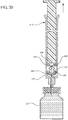
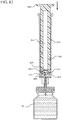
- Figures 1-13 illustrate one of more embodiments of a medical device 100 according to a first aspect of the invention.
- the medical device 100 includes a plunger rod 140 attached to a stopper 160.
- the medical device 100 is shown in use with a container in the form of a syringe barrel 110 with needle hub 180 in Figures 1-13 .
- the syringe barrel 110 includes an open proximal end 119 and a distal end 111 and a distal wall 112.
- a sidewall 114 extends from the distal end 111 to the open proximal end 119 and includes an interior surface 116 that defines a chamber 118 for retaining or holding fluids, which may include liquid medication and/or other liquids.
- the distal end 111 may also include a tip 120 having an open passageway 122 therethrough in fluid communication with the chamber 118.
- the barrel 110 may include an optional finger flange 124 at the open proximal end 119 extending radially outwardly from the sidewall 114.
- a needle hub 180 is utilized to attach the needle cannula 184 to the tip 120.
- the needle hub 180 includes a needle cannula 184 with a lumen 186 or opening therethrough and may be attached to the tip 120 so that the lumen 186 is in fluid communication with the open passageway 122 and the chamber 118.
- the needle hub 180 includes a distal end 181 and a proximal end 189 and a body 182 defining a hollow space 188.
- the tip 120 is inserted into the hollow space 188 through the open proximal end 189 of the needle hub 180 until the body 182 frictionally engages the tip 120.
- the needle cannula 184 may be attached to the tip 120, without the use of a needle hub, using other methods known in the art.
- the interior surface 116 of the syringe barrel 110 may have a smooth surface that is free of any protrusions or depressions.
- the body 182 of the needle hub 180 may also incorporate a smooth interior surface that is free of any protrusions or depressions.
- the plunger rod 140 and stopper 160 are inserted into the open proximal end 119 of the syringe barrel 110.
- the stopper 160 includes a distal end 161 and a proximal end 169.
- the stopper 160 includes an expandable portion 162 adjacent to the proximal end 169, an outside surface 163 and an inside surface 164 defining a stopper cavity 166.
- the stopper 160 further includes a sealing portion 168 formed adjacent to the distal end 161.
- the stopper 160 may be formed from an elastomeric material, polymeric material or other material known in the art.
- the sealing portion 168 may be formed from an elastomeric material having greater rigidity than the elastomeric material forming the expandable portion 162.
- the expandable portion 162 may be formed from a compressible elastomeric material, for example, a rubber material.
- the sealing portion 168 includes at least one peripheral seal 170 shaped to form a fluid-tight seal with the interior surface 116 of a syringe barrel.
- the embodiments shown in Figures 4-6 include two peripheral edges.
- the peripheral seal 170 may have a circular cross-section for forming a fluid-tight seal with a syringe barrel having an interior surface 116 with a circular cross-section.
- the sealing portion 168 and/or peripheral seal 170 may be formed from a material suitable for forming a fluid-tight seal with the interior surface 116 of the syringe barrel and may include the same or different material utilized to form the stopper 160.
- the expandable portion 162 is utilized to create a vacuum within the stopper cavity 166 by operating as a positive displacement pump by expanding the stopper cavity 166, which is sealed when the medical device are positioned with the open lumen 186 of the needle cannula 184 is submerged in the liquid to be aspirated into the syringe barrel 110.
- the pressure differential between the stopper cavity 166 and the chamber 118 draws the air within the chamber 118 into the stopper cavity 166, as will be discussed in greater detail below.
- the expandable portion 162 of the stopper 160 includes a bendable wall 172. In the embodiments shown in Figures 1-13 , the bendable wall 172 includes a single bend or corrugation.
- the bendable wall 172 may include two or more bends or corrugations.
- the volume of the stopper cavity 166 expands and contracts as the length of the bendable wall 172 increases and decreases, respectively. Changes in the length and/or cross-sectional width of the bendable wall 172 cause the expandable portion 162 to compress to a compressed state, as shown in Figures 3-5 , and expand to an expanded state, as shown in Figures 6 and 7 . As shown in Figures 12 and 13 , the length and/or cross-sectional width of the bendable wall 172 may decrease as an initial force is applied to the stopper 160 in the distal direction.
- the length and/or cross-sectional width of the bendable wall 172 of one or more embodiments may increase as the plunger rod 140 exerts an initial force is applied to the stopper 160 in the proximal direction, for example, during aspiration of a syringe barrel.
- the length and/or cross-sectional width of the bendable wall 172 may increase as the plunger rod 140 exerts an initial force to the stopper 160 in the distal direction, for example, during expulsion of the liquid from the syringe barrel.
- the expansion of the length of the bendable wall 172 is shown in Figures 8 and 9 and will be discussed in greater detail below.
- the bendable wall 172 resists compression after expansion.
- the bendable wall 172 is molded or formed to have a geometry that creates a spring-like effect or reaction to the application of forces in the distal and/or proximal direction.
- the expandable portion 162 may be formed from an elastomeric material or other material that has a spring constant to expand and compress during normal operation of the medical device 100 and syringe barrel 110. Specifically, in one or more embodiments, the expandable portion 162 has permits expansion so the user does not experience any significant tactile response to the expansion and/or is not required to take active steps to expand the stopper 160.
- the spring constant of the expandable portion 162 may be modified depending on the application and the viscosity of the liquid to be aspirated into the syringe barrel 110.
- the stopper 160 may be provided and assembled with the plunger rod in a compressed state, as shown in Figure 8 . In one or more embodiments, the user may compress the stopper prior to assembly with the plunger rod 140 and the syringe barrel 110 or other container.
- the bendable wall 172 has a single inward bend or single pinched area.
- the bendable wall 172 is compacted inwardly to reduced length and/or cross-sectional width of the expandable portion 162, reducing the size and/or volume of the stopper cavity 166.
- Expansion of the bendable wall 172 shown in Figures 3-5 is shown in Figures 6 and 7 , where the single inward bend or single pinched area is expanded or released and the length and/or cross-sectional width of the bendable wall 172 expands to expand the size and/or volume of the stopper cavity 166 from a compressed state to an expanded state.
- the bendable wall 172 may curve inwardly to reduce the length and/or cross-sectional width of the expandable portion 162.
- the expandable portion 162 may include a collapsible wall (now shown) having more than one telescoping segment that reduce and expand the length and/or cross-sectional width of the expandable portion 162.
- the length and/or cross-sectional width of the expandable portion 162 of the stopper may be pre-defined for specific applications. In one or more embodiments, the length and/or cross-sectional width of the expandable portion 162 may be sized to draw in a pre-defined amount of air trapped within a syringe barrel 110. In a specific embodiment, the length and/or cross-sectional width of the expandable portion 162 may be sized to draw in a pre-defined amount of air trapped within the tip of a syringe. In a more specific embodiment, the volume of the stopper cavity 166 may be sized to hold a pre-defined amount of air trapped within a syringe barrel. In a specific embodiment, the volume of the stopper cavity 166 may be sized to hold a pre-defined amount of air trapped within the tip of a syringe.
- the distal end 161 of the stopper 160 includes a distal face 174 including an opening 171 and a porous portion 190 and the proximal end 169 of the stopper 160 includes a proximal wall 176 having an aperture 178 defined by a rim 179.
- the distal face 174 also includes a conduit 175 in fluid communication with the stopper cavity 166 and the opening 171.
- the distal face 174 is flexible and flexes concavely and convexly, as will be described in greater detail with reference to Figures 8-13 .
- the distal face 174 may also be shaped convexly so that it conforms more closely to the shape of the distal wall 112 of the syringe barrel 110 to expel as much liquid from the chamber 118 as possible.
- a porous portion 190 is disposed in the conduit 175 and/or opening 171 and in fluid communication with the conduit 175, stopper cavity 166 and the opening 171.
- the porous portion 190 is air permeable and liquid impermeable.
- the porous portion 190 forms a selective barrier that a liquid penetration pressure and an air penetration pressure that is less than the liquid penetration pressure.
- the porous portion 190 may have a circular shape. Alternatively, the porous portion 190 may have a square and/or rectangular shape. In one embodiment, the porous portion 190 may be integrally formed or disposed on the distal face 174, adjacent to the opening 171. In a specific embodiment, the porous portion has a cross-sectional width that is smaller than the cross-sectional width of the distal face 174. The porous portion may also be integrally formed and/or disposed adjacent to the conduit 175 on the inside surface 164 of the stopper. In a specific embodiment, the porous portion 190 may have a cross-sectional with that is smaller than the cross-sectional width of the inside surface 164 of the stopper.
- the porous portion 190 can be integrally formed on the distal face 174 and covers the opening 171, with the peripheral edges of the distal face 174 and the sealing portion 168 remaining non-porous. In a specific embodiment, the porous portion 190 is separated from the sealing portion 168 by the distal face 174. In a more specific embodiment, the porous portion 190 is separated from the sealing portion 168 by the peripheral seal 170.
- the porous portion may also be shaped to fit within the opening 171 and form a fluid-tight engagement with the opening.
- the porous portion may extend from the distal face 174 into the conduit 175.
- the porous portion 190 may have a periphery that is molded to a portion of the distal face 174.
- the porous portion 190 may be attached to the distal face 174 of the stopper by mechanical means, for example, adhesives and/or molding.
- the distal face 174 may include a pocket (not shown) for securing the porous portion 190 adjacent to the distal face 174 and the opening 171.
- the porous portion 190 may include a hydrophobic filter, swellable polymer, other materials that are air permeable and liquid impermeable and/or combinations thereof, as described above.
- the medical device 100 includes a structure for venting the air evacuated through the porous portion 190 from the medical device 100 and/or syringe barrel 110.
- the proximal wall 176 of the stopper 160 may include an undercut 173 adjacent the rim 179 that defines the aperture 178.
- the aperture 178 is sized and/or shaped to permit attachment of the plunger rod 140 to the stopper 160.
- the undercut 173 is sized and shaped to form a releasable seal between the plunger rod 140 and stopper 160 and prevent fluid communication between the stopper cavity 166 and the aperture 178. When released, the releasable seal also forms a vent for the evacuated air.
- the plunger rod 140 includes a distal end 141, a proximal end 149, and an elongate body 142 extending from the distal end 141 and the proximal end 149.
- the plunger rod 140 may be made of a rigid plastic or other material that has a greater rigidity than the stopper 160. Examples of such materials include polypropylene, polyethylene, polycarbonate and combinations thereof.
- the elongate body 142 may be cylindrical.
- the shape of the elongate body 142 may be rectangular, or may be formed by two perpendicularly intersecting beams.
- the proximal end 149 of the plunger rod 140 includes an optional thumbpress 148.
- the distal end 141 of the plunger rod 140 includes a stopper-engaging portion 150.
- the stopper-engaging portion 150 is shaped to fit within the stopper cavity 166 of the stopper 160 and to retain the stopper 160 at the distal end 141 of the plunger rod.
- the plunger rod 140 and stopper 160 may be integrally formed or permanently attached, while allowing the stopper 160 to expand and compress.
- the stopper-engaging portion 150 has a size and shape to allow a slidable engagement between the plunger rod 140 and the stopper 160. Specifically, the stopper-engaging portion 150 of the plunger rod may be able to slide distally and proximally within the stopper cavity 166 of the stopper 160, while maintaining the attachment or engagement between the plunger rod 140 to the stopper 160.
- the stopper-engaging portion 150 includes a tapered neck portion 156 distally adjacent the elongate body 142 of the plunger rod 140.
- a first protrusion 152 is positioned distally adjacent the tapered neck portion 156, a boss member 153 distally adjacent the first protrusion 152 and a second protrusion 154 distally adjacent the boss member 153.
- the first protrusion 152 has a cross-sectional width to prevent separation of the plunger rod 140 from the stopper 160 and, more specifically, the separation between the plunger rod 140 from the rim 179 of the stopper 160.
- the second protrusion 154 includes a perpendicular face 158, which have a cross-sectional width equal to or greater than the cross-sectional width of opening 171 and/or the porous portion 190 to block the air evacuated into the stopper cavity 166 from entering the chamber 118 of the syringe barrel 110 or other container during expulsion of the aspirated liquid from the syringe barrel 110.
- the second protrusion 154 blocks or covers the opening 171 and/or porous portion 190 and forces the air within the stopper cavity 166 of the stopper to escape through the aperture 178 when the releasable seal between the tapered neck portion 156 of the plunger rod and rim 179 and/or undercut 173 of the stopper 160 is released.
- the first and/or second protrusions 152, 154 may be disc shaped.
- the first and/or second protrusions 152, 154 may have a rectangular or square cross-section. Alternative constructions may provide a variety of shapes, which may be identical to each other or different from each other.
- the first protrusion 152 may be shaped to prevent separation of the plunger rod from the stopper.
- the second protrusion 154 may be shaped to prevent air that has already been evacuated into the stopper cavity 166 from entering the chamber 118 through the porous portion 190, for example, as a force in the distal direction is applied to the plunger rod to expel the liquid from within the chamber 118.
- the boss member 153 and/or the stopper 160 have a length that permits the stopper-engaging portion 150 to move distally and proximally within the stopper cavity 166 of the stopper 160 a pre-selected axial distance Dl relative to the stopper 160, as shown more clearly in Figure 11 .
- the boss member 153 has a length that permits such movement of the plunger rod 140 without separation of the plunger rod 140 from the stopper 160.
- the movement of the plunger rod 140 for the length D1 relative to the stopper 160 permits the plunger rod 140 and the first protrusion 152 to exert enough force on the inside surface 164 of the stopper to facilitate the expansion of the expandable portion 162 of the stopper.
- the cross-sectional width and length of the boss member 153 may be sized to allow the stopper-engaging portion 150 to fit within the stopper cavity 166 of the stopper 160 when the stopper 160 is an unexpanded or compressed state.
- the tapered neck portion 156 of the stopper-engaging portion 150 may be shaped to form a seal with the rim 179 of the stopper 160 at the aperture 178. As will be described more fully below, formation of a seal between the plunger rod 140 and the rim 179 at the aperture 178 of the stopper ensures a vacuum is created between the distal face 174 of the stopper 160 and the chamber 118 of the syringe barrel 110 or other container so that fluid may be aspirated into the chamber 118.
- the structure of the stopper-engaging portion 150 and/or plunger rod 140 prevents the seal from being released during aspiration but permits the release of the seal when the liquid is being expelled from the chamber 118 of the syringe barrel 110 so the air within the stopper cavity 166 may be vented.
- the tapered neck portion 156 of the stopper engaging-portion 150 may be shaped to form a releasable seal with the rim 179 at the aperture 178 of the stopper.
- the tapered neck portion 156 has a cross-sectional width that increases from the elongate body 142 of the plunger rod to the first protrusion 152.
- the cross-sectional width of the tapered neck portion 156 increases at the same angle as the angle of the undercut 173 of the stopper 160.
- the tapered neck portion 156 is contoured so that at least one portion of the tapered neck portion 156 forms a fluid-tight engagement with the undercut 173 as the plunger rod 140 and stopper 160 move in the proximal direction.
- the tapered neck portion 156 forms a seal with the rim 179 of the stopper 160 that can be formed and released as the plunger rod 140 moves distally and proximally relative to the stopper 160.
- the plunger rod 140 and stopper 160 are assembled as medical device 100 and are inserted into the open proximal end 119 of the syringe barrel 110.
- the distal face 174 of the stopper 160 is positioned adjacent to the distal wall 112 of the syringe barrel 110, so the air within the chamber 118 is minimized and is primarily present in the tip 120 of the syringe barrel 110 or other container.
- the distal face 174 is flexed concavely to further minimize the air within the chamber 118 by applying a force to the plunger rod in the distal direction, prior to aspirating liquid into the chamber 118.
- the expandable portion 162 of the stopper 160 is configured to a compressed state (as also shown in Figures 3-5 and 8 ). Before use, the user may compress the stopper before assembly with the plunger rod 140 and the syringe barrel 110 and/or other container.
- the needle cannula 184 is inserted into a container, such as a vial 50, to draw the liquid from a vial into the chamber 118 of the syringe barrel 110, as shown in Figure 9 .
- a proximally directed force is applied to the plunger rod 140 so that the stopper-engaging portion 150 applies a proximally directed force to the inside surface 164 of the proximal wall 176 of the stopper.
- the application of this proximally directed force causes or allows the expandable portion 162 to expand to an expanded state, as demonstrated in Figures 8 , 9 and 9A .
- the tapered neck portion 156 forms a seal with the rim 179 and undercut 173.
- the expansion of the expandable portion 162 creates a "spring back" motion that creates a vacuum within the stopper cavity 166 of the stopper 160, drawing air and liquid into the chamber 118.
- the porous portion 190 of the stopper permits air present within the chamber 118 and/or tip 120 to permeate therethrough into the stopper cavity 166 of the stopper.
- the vacuum within the stopper cavity 166 draws air and possibly liquid into the chamber 118 prior to the creation of a vacuum within the chamber 118 caused by the movement of the stopper 160 in the proximal direction.
- the expansion of the expandable portion 162 may draw some liquid into the needle cannula 184 and chamber 118 before the stopper 160 moves, however, the porous portion 190 prevents liquid from permeating through the porous portion 190 into the stopper cavity 166.
- Expansion of the expandable portion 162 shown in Figures 3-5 is shown in Figures 6 and 7 , where the single inward bend or single pinched area is released and the length and/or cross-sectional width of the bendable wall 172 expands to expand the size or volume of the stopper cavity 166.
- the user may apply a continuous force on the plunger rod 140 and stopper 160 without having to wait for the air to be drawing into the stopper cavity 166 from the chamber 118.
- the continued application of a proximally directed force to the plunger rod 140 during a normal aspiration step causes the plunger rod 140 and stopper 160 to move together in the proximal direction.
- the peripheral seal 170 of the stopper 160 forms a fluid-tight seal with the interior surface 116 of the syringe barrel 110 or other container and the tapered neck portion 156 continues to form a seal with the rim 179 and undercut 173.
- the movement of the plunger rod 140 and stopper 160 in the proximal direction creates a vacuum within the chamber 118.
- the air drawn into the chamber 118 rises above the liquid toward the stopper 160 and permeates through the porous portion 190 into the stopper cavity 166 of the stopper.
- the syringe barrel 110 will be positioned vertically so that the liquid aspirated into the chamber 118 forms a column of liquid and air trapped within the chamber 118 rises to the top of the liquid column.
- the air then permeates through the porous portion 190 into the stopper cavity 166 of the stopper 160.
- the liquid forms a column that approaches the porous portion 190 until the air is evacuated from the chamber 118 into the stopper cavity 166 and no air remains in the chamber 118, as shown in Figure 11 .
- the porous portion 190 prevents the liquid from permeating through the porous portion into the stopper cavity 166.
- the fluid-tight seal between the peripheral seal 170 and interior surface 116 of the syringe barrel and the application of a proximally directed force to the plunger rod 140 and stopper 160 causes the distal face 174 to flex concavely.
- the concave shape of the distal face 174 during aspiration permits more air to permeate through the porous portion 190 before the liquid reaches the porous portion 190.
- the porous portion 190 prevents liquid from entering the stopper cavity 166 and the liquid may be expelled from the chamber 118 without taking any additional steps to remove air from the chamber 118.
- a distally directed force is applied to the plunger rod 140, causing the plunger rod 140 to move the pre-selected axial distance D 1, as shown in Figure 11 , in the distal direction relative to the stopper while the stopper 160 remains stationary, as shown in Figure 12 .
- Movement of the plunger rod 140 in the distal direction relative to the stopper 160 releases the proximally directed force that was applied to the inside surface 164 of the proximal wall 176 of the stopper by the plunger rod 140.
- the release of the proximally directed force on the inside surface 164 of the proximal wall 176 allows the expandable portion 162 of the stopper to collapses or compress into an unexpanded state.
- the plunger rod 140 and stopper 160 move together in the distal direction.
- the peripheral seal 170 of the stopper 160 continues to form a fluid tight seal with the interior surface 116 of the syringe barrel 110.
- the expandable portion 162 of the stopper 160 remains collapsed or compressed in an unexpanded state.
- the movement of the plunger rod 140 in the distal direction relative to the stopper 160 releases the seal and allows the air contained within the stopper cavity 166 to be released through the aperture 178.
- the distal movement of the plunger rod 140 relative to the stopper 160 permits the perpendicular face 158 of the stopper engaging portion 150 to cover the porous portion 190 and block the conduit 175 and prevent the air contained within the stopper cavity 166 from escaping through the porous portion 190 toward the chamber 118.
- the position of the perpendicular face 158 over the porous portion 190 forces the air to escape through the aperture 178 or remain within the stopper cavity 166 of the stopper.
- the plunger rod 140 may be locked in a fixed relationship with respect to the stopper after the initial distal movement of the plunger rod 140 relative to the stopper 160.
- the distal end 161 of the stopper 160 may include a rim or other locking structure (not shown) for retaining the second protrusion 154 of the plunger rod 140.
- the plunger rod 140 and stopper 160 move together in the proximal and distal directions in a fixed relationship.
- the expandable portion 162 of the stopper collapses or compresses to an unexpanded state as the plunger rod 140 and the stopper 160 move together in the proximal and distal directions.
- the expandable portion 162 of the stopper 160 resists compression so that the air within the stopper cavity 166 does not escape through the porous portion 190 in the distal direction and remains within the stopper cavity 166.
- the continued application of a distally directed force to the plunger rod 140 or continuous movement of the plunger rod 140 and stopper 160 in the distal direction causes the perpendicular face 158 of the stopper-engaging portion 150 to contact the inside surface 164 of the stopper 160 adjacent to the conduit 175 and causes the plunger rod 140 and stopper 160 to move in the distal direction together.
- the application of a continuous and distally directed force to the plunger rod 140 causes the distal face 174 to flex convexly as the distal face 174 contacts the distal wall 112 of the syringe barrel 110.
- the distal face 174 conforms more closely to the distal wall 112 upon contact with the distal wall 112.
- the convex shape of the distal face 174 forces more liquid out of the chamber 118, allowing more accurate dosing, as shown in Figure 13 .
- a second aspect of the present invention pertains to a medical device 200 that utilizes a stopper assembly, including a stopper 260 and a stopper hub 250, wherein the stopper hub 250 utilizes a pump body 253.
- the pump body 253 includes a bendable wall in the shape of a bellows or having corrugated or accordion-style walls.
- Figures 14-25 One or more embodiments according to the second aspect of the present invention are shown in Figures 14-25 .
- the term "bellows" as used herein is used to describe a structure possessed by what are traditionally referred to as bellows or accordion-style walls.
- bellows also includes the alterable structure achieved by repeated corrugations or bends extending around the circumference or perimeter of a body.
- the term “bellows” also includes other deformable containers or flexible or semi-flexible fluid enclosures or containers that may hold fluid and function as a pump, such as diaphragm devices, springs, and the like.
- the medical device 200 shown in Figures 14-25 includes a plunger rod 240 attached to stopper hub 250 that is attached or integrally formed to a stopper 260.
- the medical device 200 is shown in use with a container in the form a syringe barrel 210 with a needle cannula 284 attached thereto.
- the syringe barrel 210 includes an open proximal end 219 and a distal end 211 and a distal wall 212.
- a sidewall 214 extends from the distal end 211 to the open proximal end 219 and includes an interior surface 216 that defines a chamber 218 for retaining or holding fluids, which may include liquid medication and/or other liquids.
- the distal end 211 may also include a tip 220 having an open passageway 222 therethrough in fluid communication with the chamber 218.
- the distal end 211 of the syringe barrel 210 includes an optional luer fitting 288.
- the open proximal end 219 of the syringe barrel 210 may include a flange 224.
- a needle cannula 284 is attached directly to the tip 220.
- a needle hub (not shown) may be used to attach a needle to the tip.
- the interior surface 216 of the syringe barrel 210 may have a smooth surface that is free of any protrusions or depressions.
- the plunger rod 240, stopper hub 250 and stopper 260 are inserted into the open proximal end 229 of the syringe barrel 210.
- the stopper 260 includes a distal end 261 and an open proximal end 269.
- the stopper 260 includes body 262 extending from the distal end 261 to the open proximal end 269, an outside surface 263 and an inside surface 264 defining a stopper cavity 266.
- the inside surface 264 of the body 262 may include a peripheral channel 268 forming a groove or ridge within the body for engagement with the stopper hub 250, as will be described in detail below and is shown more clearly in Figure 16 .
- the outside surface 263 of the body 262 includes a sealing portion 270.
- the sealing portion 270 is disposed on the outside surface 263 adjacent the distal end 261, however, it may also be formed at any location on the outside surface 263 along the length of the body 262.
- the stopper 260 may be formed from an elastomeric material, polymeric material or other suitable material known in the art.
- the sealing portion 270 may includes one or more grooves (not shown) shaped to form a fluid-tight seal with the inside surface of a syringe barrel.
- the sealing portion 270 may have a circular cross-section for forming a fluid-tight seal with a syringe barrel having an interior surface with a circular cross-section.
- the sealing portion 270 may be formed from a material suitable for forming a fluid-tight seal with the interior surface 216 of the syringe barrel and may include the same or different material utilized to form the stopper 260.
- the distal end 261 of the stopper 260 includes a convex distal face 272 having an opening 274 therethrough in fluid communication with the stopper cavity 266.
- the distal end 261 of the stopper may also include a path 276 in fluid communication with the stopper cavity 266 and the opening 274.
- the distal face 272 may be shaped convexly so that it conforms more closely to the shape of the distal wall 212 of the syringe barrel 210 to expel as much liquid from the chamber 218 as possible.
- the distal face 272 may be flexible (not shown) and may flex concavely and convexly.
- a porous portion 290 is disposed in the path 276 and/or opening 274 and in fluid communication with the path 276, stopper cavity 266 and the opening 274.
- the porous portion 290 is air permeable and liquid impermeable.
- the porous portion 290 forms a selective barrier that a liquid penetration pressure and an air penetration pressure that is less than the liquid penetration pressure.
- the porous portion 290 has a circular shape. Alternatively, the porous portion 290 may have a square and/or rectangular shape. In one or more embodiments, the porous portion 290 may be integrally formed or disposed on the distal face 272, adjacent to the opening 274. In a specific embodiment, the porous portion has a cross-sectional width that is smaller than the cross-sectional width of the distal face 272. The porous portion may also be integrally formed and/or disposed adjacent to the path 276 on the inside surface 264 of the stopper. In a specific embodiment, the porous portion 290 may have a cross-sectional with that is smaller than the cross-sectional width of the inside surface 264 of the stopper.
- the porous portion 290 may be integrally formed on the distal face 272, with the peripheral edges of the distal face 272 and the sealing portion 270 remaining non-porous. Alternatively, the porous portion 290 is separated from the sealing portion 270 by the distal face 272.
- the porous portion 290 may also be shaped to fit within the opening 274 and form a fluid-tight engagement with the opening 274.
- the porous portion 290 may extend from the distal face 272 into the path 276.
- the porous portion 290 may have a periphery that is molded to a portion of the distal face 272.
- the porous portion 290 may be attached to the distal face 272 of the stopper by mechanical means, for example, adhesives and/or molding.
- the distal face 272 may include a pocket (not shown) for holding and securing the porous portion 290 adjacent to the distal face 272 and the opening 274.
- the stopper hub 250 includes an open distal end 251 and an open proximal end 259.
- the stopper-engaging portion 252 includes an aperture 255 in fluid communication with the stopper cavity 266, path 276 and opening 274.
- the open distal end includes a stopper-engaging portion 252, which may be provided in the form of a disc extending radially outwardly, for attachment of the stopper hub 250 to the stopper 260.
- the stopper-engaging portion 252 extends radially outwardly to engage the peripheral channel 268 of the stopper 260.
- the stopper-engaging portion 252 may be in the form of a tab (not shown), which corresponds to an opening or other corresponding structure on the inside surface 264 of the stopper.
- the stopper-engaging portion 252 may have an opening and the inside surface 264 of the stopper may include a tab extending radially inwardly to engage with the opening of the stopper 260.
- Other means to engage the stopper hub 250 to the stopper 260 may also be utilized.
- the stopper 260 may be integrally formed on the distal end 251 of the stopper hub 250 and the stopper 260 and the stopper hub 250 may be provided as a single unit.
- the stopper hub 250 includes a pump body 253 and a plunger engaging portion 230 for attaching the stopper assembly to a plunger rod, as will be described in more detail below.
- the pump body 253 includes a wall 254 defining a pump cavity 258 in fluid communication with the opening 274 and the stopper cavity 266.
- the pump body 253 is utilized to create a vacuum within the stopper hub 250 and stopper 260 assembly by operating as a positive displacement pump to expand the pump cavity 258 when sealed.
- the pressure difference between the pump cavity 258 and the chamber 218 and stopper cavity 266 draws air and possibly liquid within the chamber 218 into the pump cavity 258.
- the wall 254 is provided in the shape of a bellows or having a plurality of corrugations that can fold into one another to collapse and expand the length of the wall 254.
- the pump cavity 258 has a volume that varies as the wall 254 expands and collapses.
- the wall 254 may be configured to compress and remain compressed upon application of a force on the pump body 253 in the distal direction.
- the wall 254 may be configured expand and remain in an extended length when no force is being applied the bellows.
- the wall 254 may include a spring-type insert (not shown) that maintains an extended length or expanded state and may require a force to be applied to it to reach a compressed state.
- the wall 254 may require a continuous force to be applied to it or compressing force to remain in a compressed state.
- the wall 254 is formed from an elastomeric material. The elastomeric material can be used to form the wall and may be modified so that the wall 254 possesses a spring constant that allows rapid expansion from a compressed state.
- the pump body 253 may resist compression after air enters the pump cavity 258.
- the wall 254 includes two bends 256, 257 that fold together to shorten or collapse the length of the wall 254
- the wall 254 may include more than two bends or corrugations or, alternatively, include a single bend or corrugation.
- the volume of the pump cavity 258 expands and contracts as the length of the wall 254 increases and decreases. Changes in the length and/or cross-sectional width of the wall 254 cause the pump body 253 to compress to a compressed state and expand to an expanded state, as shown in Figures 19 and 20 .
- the length and/or cross-sectional width of the wall 254 may decrease as an initial force is applied to the plunger rod 240 in the distal direction.
- the length and/or cross-sectional width of the wall 254 increases as the force applied to the plunger rod 240 in the distal direction is released. In a specific embodiment, the length and/or cross-sectional width of the wall 254 increases as an initial force is applied to the stopper 260 in the proximal direction, for example, during aspiration of a syringe barrel.
- the wall 254 resists compression after expansion.
- the wall 254 is molded or formed to have a geometry that creates a spring-like effect or reaction to the application of forces in the distal and/or proximal direction.
- the wall 254 is initially in an expanded state and may require application of a force to be compressed.
- the wall 254 may be formed from an elastomeric material or other material that has a spring constant to expand and compress during normal operation of the medical device 200 and syringe barrel 210.
- the wall 254 has a spring constant that permits expansion in a rapid manner in a rapid manner so the user does not experience any significant tactile response to the expansion and/or is not required to take active steps to expand the stopper 260.
- the spring constant of the wall 254 may be modified depending on the application and the viscosity of the liquid to be aspirated into the syringe barrel 210.
- the wall 254 is compacted inwardly at the two bends 256, 257 to have a reduced length and/or cross-sectional width of the pump body 253, resulting in reducing the size or volume of the pump cavity 258. It will be understood the wall 254 may curve inwardly to reduce the length and/or cross-sectional width of the pump body 253. Alternatively, the pump body 253 may include a collapsible wall (now shown) having more than one telescoping segment that reduce and expand the length of the pump body 253.
- the length and/or cross-sectional width of the pump body 253 of the stopper may be pre-determined for specific applications.
- the length and/or cross-sectional width of the pump body 253 may be sized to draw in a pre-determined amount of air trapped within a syringe barrel.
- the length and/or cross-sectional width of the pump body 253 may be sized to draw in a pre-determined amount of air trapped within the tip of a syringe.
- the volume of the pump cavity 258 may be sized to hold a pre-determined amount of air trapped within a syringe barrel.
- the volume of the pump cavity 258 may be sized to hold a pre-determined amount of air trapped within the tip of a syringe.
- the stopper hub 250 includes a plunger-engaging portion 230 that includes an open distal end 231 and an open proximal end 239 and an inside surface 233 defining a socket 235 configured to frictionally engage the outside surface of the plunger rod 240, as will be described below.
- the socket 235 includes a groove 236 disposed along the inside surface 233 forming a fitting for the distal end of the plunger rod.
- a plurality of grooves may be disposed along the inside surface 233 for gripping the distal end of the plunger rod 240.
- the plunger-engaging portion 230 includes one or more indentations (not shown) disposed along the inside surface 233 for receiving the distal end of the plunger rod 240, which may include a plurality of corresponding tabs (not shown) which form a frictional fit with the indentations.
- the inside surface 233 may have a textured surface or a coating (not shown) that creates or increases frictional interference with the distal end of the plunger rod 240.
- the plunger rod 240 and stopper hub 250 may be integrally formed or permanently attached using methods know in the art.
- the distal end 231 of the plunger-engaging portion includes an outlet 237 and a valve 238.
- the outlet 237 is in fluid communication with the socket 235.
- the valve 238 comprises a one-way valve configured to open to permit fluid communication between the pump cavity 258 and the outlet 237.
- the outlet 237 when sealed, facilitates the formation of a vacuum within the chamber 218 of the syringe.
- the valve 238 may be in form of any one-way valve or check valve that opens in one direction.
- the valve 238 provides a means for venting the air evacuated into the pump cavity 258. In a specific embodiment, the valve 238 provides a relief valve for the pump cavity 258. In one or more embodiments the distal end of the plunger-engaging portion does not include a valve 238 and the outlet 237 is in fluid communication with the pump cavity 258. In a specific embodiment, the distal end of the plunger rod 240 is enclosed and does not include an outlet 237 or a valve 238.
- valve 238 closes during expansion of the wall 254 and seals the outlet 237 from the socket 235. During compression or when the wall 254 is collapsing, the valve 238 opens. In one or more embodiments, the valve 238 is in the form of a flap.
- a plunger rod 240 is attached to the proximal end 259 of the stopper hub.
- the plunger rod 240 shown more clearly in Figure 14 includes a distal end 241, a proximal end 249, and an elongate body 242 extending from the distal end 241 and the proximal end 249.
- the plunger rod 240 may be made of a rigid plastic or other material that has a greater rigidity than the stopper 260. Examples of such materials include polypropylene, polyethylene, polycarbonate and combinations thereof.
- the elongate body 242 may be cylindrical. In one or more embodiments, the shape of the elongate body 242 may be rectangular or other shape.
- the proximal end 249 of the plunger rod 240 includes an optional thumbpress 248.
- the body 242 may include a cavity (not shown), which may be in fluid communication with the pump cavity 258.
- the distal end 241 of the plunger rod includes a structure for engaging the stopper hub 250.
- the distal end 241 of the plunger rod includes such a structure for engaging the stopper hub 250 in the form of a distal portion 245, having a disc-shaped plug 243 disposed perpendicularly to the elongate body 242 of the plunger rod.
- the disc-shaped plug 243 may include a beveled adjacent to the distal end 241 of the plunger rod.
- the disc-shaped plug 243 includes one beveled edge disposed on the distal side of the plug 243 and one beveled edge on the proximal side of the plug 243.
- the beveled edge may be formed around the periphery of the disc-shaped plug 243.
- the distal end 241 of the plunger rod 240 may include an optional a neck portion 244 proximally adjacent to the disc-shaped plug 243 disposed between the disc-shaped plug 243 and the distal portion 245.
- the plunger rod 240 may also include two peripheral ribs 246, 247 disposed along the elongate body 242 and positioned proximally adjacent the neck portion 244.
- the plunger rod 240 may not include a neck portion 244 and the disc-shaped plug 243 may be formed at the distal end of the plunger rod 240 adjacent to the elongate body 242.
- the distal portion 245 includes a recess 292 allowing space for the valve 238 to open, as will be described below.
- the plunger rod 240 including a recess, stopper hub 250 and stopper 260 are assembled as a medical device 200 and are inserted into the open proximal end 219 of the syringe barrel 210.
- the distal face 272 of the stopper 260 is positioned adjacent to the distal wall 212 of the syringe barrel 210, so that the air within the chamber 218 is minimized and is primarily present in the tip 220 of the syringe barrel 210 or other container.
- the stopper hub 250 and the plunger rod 240 form a unitary piece that moves together distally and proximally within the chamber.
- the wall 254 causes the stopper 260 to remain stationary with respect to movement of the plunger rod 240, as the length of the stopper hub 250 is elongated or expanded.
- the wall 254 is in an expanded state before use.
- an initial distally directed force is applied to the plunger rod 240, as shown in Figures 18 and 19 .
- the user may insert the needle cannula 284 into a vial and submerge it into the liquid applying the force to the plunger rod 240 in the distal direction to compress the wall 254.
- the compression of the wall 254, after inserting the needle cannula 284 into vial 50 causes air within the pump cavity 258 to escape through the needle cannula 284 and lumen 286 and also possibly through the open valve 238, which opens during compression of the wall 254, as shown in Figures 18 and 19 .
- the user may apply a force in the distal direction to the plunger rod 240 and compress the wall 254 prior to inserting the needle cannula 284 into the vial 50 (not shown).
- the user would continue to apply the distally directed force on the plunger rod 240 and then submerge the lumen 286 in the liquid contained within the vial.
- the compression of the wall 254 prior to inserting the needle cannula 284 into vial 50 causes air within the pump cavity 258 to escape through the lumen 286 and the open valve 238 and outlet 237, which opens during compression of the wall 254.
- the user releases the force applied to the plunger rod 240 in the distal direction.
- the spring constant and properties of the wall 254 cause the wall 254 to expand from the compressed state to an expanded state upon the release of the force applied on the plunger rod 240 in the distal direction.
- the release of the force applied to the plunger rod 240 also causes the stopper 260 to remain stationary and causes the plunger rod 240 to move proximally, as the length of the wall 254 expands.
- the expansion of the pump cavity 258 creates a vacuum within the pump cavity 258, which causes the valve 238 to close, as shown more clearly in Figures 20 and 21 .
- the expansion of the pump cavity 258 causes any air present within the needle cannula 284 and the syringe barrel 210 to be evacuated into the pump cavity 258, through the porous portion 290 of the stopper 260.
- the expansion of the pump cavity 258 may cause some liquid to be drawn into the tip 220 and/or chamber 218 prior to the formation of a vacuum within the chamber 218 caused by movement of the stopper 260 in the proximal direction.
- the porous portion 290 prevents this liquid from entering the stopper cavity 266, as will be described below.
- the user applies a proximally directed force on the plunger rod 240 or, more specifically, the thumbpress 248, which draws the liquid from the vial 50 into the needle cannula 284 and into the chamber 218.
- the valve 238 remains closed and the vacuum within the pump cavity 258 is maintained and continues to draw any air present in the chamber 218 into the pump cavity 258.
- the movement of the plunger rod 240 relative to the stopper 260, when the wall 254 is expanded, and movement of the plunger rod 240, stopper hub 250 and stopper 260 together in the proximal direction occurs as part of a continuous aspiration stroke that is similar to an aspiration stroke using conventional syringes known in the art.
- any remaining air rises to the top of the aspirated liquid or between the liquid and the distal face 272 of the stopper 260. This remaining air permeates through the porous portion 290 and the liquid is prevented from passing through the porous portion 290 into the stopper cavity 266.
- the porous portion may be formed from hydrophobic filter, a swellable polymer and combinations thereof, as described herein. When the porous portion includes a swellable polymer, the openings present in the swellable polymer close upon contact with the liquid.
- FIG. 23B illustrates a syringe barrel 210 filled with liquid and no air.
- the valve 238 remains closed as the pressure within the pump cavity 258 remains lower than the pressure outside of the pump cavity 258. For example during aspiration, as the wall 254 of the pump body expands, the vacuum created within the pump cavity 258 draws the in valve 238 or forces the valve 238 closed. As the pressure within the pump cavity 258 equalizes or, as will be discussed, the user expels the liquid within the chamber 218, the valve 238 opens and vents the evacuated air from within the pump cavity 258.
- a distally directed force is applied to the plunger rod 240 and the stopper hub 250 move with the stopper 260 in the distal direction.
- the force applied to the plunger rod in the distal direction overcomes the resistance between the sealing portion 270 of the stopper 260 and the interior surface of the syringe barrel 210 and also the resistance of the wall 254 to collapsing.
- the compressed wall 254 causes the valve 238 to open and allows the air within the pump cavity 258 to escape through the outlet 237instead of through the porous portion 290.
- the recess 292 of the plunger rod provides space for the valve 238 to open.
- the application of a continuous and distally directed force on the plunger rod 240 causes the distal face 272 to flex as the distal face 272 contacts the distal wall 212 of the syringe barrel.
- the distal face 272 conforms more closely to the distal wall 212 upon contact with the distal wall 212.
- the convex shape of the distal face 272 upon contact with the distal wall 212 expels even more liquid from the syringe barrel 210.
- FIGS 26-34 illustrate a medical device 300 according a third aspect of the invention.
- the medical device 300 includes a plunger rod 340 that may be attached to a stopper hub 350 and stopper 360 assembly.
- the medical device 300 is shown in use with a container in the form a syringe barrel 310 with a needle cannula 384 attached thereto.
- the syringe barrel 310 includes an open proximal end 319 and a distal end 311 and a distal wall 312.
- a sidewall 314 extends from the distal end 311 to the open proximal end 319 and includes an interior surface 316 that defines a chamber 318 for retaining or holding fluids, which may include liquid medication and/or other liquids.
- the distal end 311 may also include a tip 320 having an open passageway 322 therethrough in fluid communication with the chamber 318.
- a needle cannula 384 includes a lumen 386 or opening therethrough and may be attached to the tip 320 so that the lumen 386 is in fluid communication with the open passageway 322 and the chamber 318.
- a needle cannula 384 is attached to the tip 320.
- a needle hub (not shown) may be used to attach a needle to the tip.
- the distal end 311 includes an option luer fitting 388 and the proximal end 319 includes an optional finger flange 324.
- the interior surface 316 of the syringe barrel 310 may have a smooth surface that is free of any protrusions or depressions. In use, the plunger rod 340, stopper hub 350 and stopper 360 are inserted into the open proximal end 319 of the syringe barrel 310.
- the stopper 360 includes a distal end 361 and an open proximal end 369.
- the stopper 360 includes a stopper body 362 extending from the distal end 361 to the open proximal end 369 that includes an inside surface 364 defining a stopper cavity 366.
- the inside surface 364 of the stopper body 362 may include a peripheral channel 368 forming a groove or ridge within the stopper body 362 for engagement with the stopper hub 350, as will be described in detail below.
- the stopper body 362 includes an outside surface 363 with a sealing portion 370.
- the sealing portion 370 is formed adjacent the distal end 361, however, the sealing portion 370 may also be formed along the entire length of the outside surface 363 or at other locations along the length of the outside surface.
- the stopper 360 may be formed from an elastomeric material, polymeric material or other suitable material.
- the sealing portion 370 includes at least one peripheral edge 372 shaped to form a fluid-tight seal with the inside surface of a syringe barrel.
- the sealing portion 370 and/or the peripheral edge 372 may be formed from a material suitable for forming a fluid-tight seal with the interior surface 316 of the syringe barrel, which may include the same or different material as the stopper 360.
- the peripheral edge 372 may have a circular cross-section for forming a fluid-tight seal with a syringe barrel having an interior surface with a circular cross-section.
- the distal end 361 of the stopper 360 includes a convex distal face 374 having an opening 376 therethrough in fluid communication with the stopper cavity 366.
- the distal end 361 of the stopper may also include a path 378 in fluid communication with the stopper cavity 366 and the opening 376.
- the distal face 374 is flexible and flexes concavely and convexly, as will be described in greater detail below.
- the distal face 374 may also be shaped convexly so that it conforms more closely to the shape of the distal wall 312 of the syringe barrel 310 to expel as much liquid from the chamber 318 as possible.
- a porous portion 390 is disposed in the path 378 and/or opening 376 and in fluid communication with the path 378, stopper cavity 366 and the opening 376.
- the porous portion 390 is air permeable and liquid impermeable.
- the porous portion 390 forms a selective barrier that a liquid penetration pressure and an air penetration pressure that is less than the liquid penetration pressure.
- the porous portion 390 may have a circular shape. Alternatively, the porous portion 390 may have a square and/or rectangular shape. In one or more embodiments, the porous portion 390 may be integrally formed or disposed on the distal face 374, adjacent to the opening 376. In a specific embodiment, the porous portion 390 has a cross-sectional width that is smaller than the cross-sectional width of the distal face 374. The porous portion 390 may also be integrally formed and/or disposed adjacent to the path 378 on the inside surface 364 of the stopper. The porous portion 390 may have a cross-sectional width that is smaller than the cross-sectional width of the inside surface 364 of the stopper. The thickness of the porous portion 390 may be adjusted so the porous portion extends along the length of the path 378.
- the porous portion 390 may be integrally formed on the distal face 374, with the peripheral edges of the distal face 374 and the sealing portion 370 remaining non-porous. In a specific embodiment, the porous portion 390 is separated from the sealing portion 370 by the distal face 374.
- the porous portion 390 may also be shaped to fit within the opening 376 and form a fluid-tight engagement with the opening 376.
- the porous portion 390 may extend from the distal face 374 into the path 378.
- the porous portion 390 may have a periphery that is molded to a portion of the distal face 374.
- the porous portion 390 may be attached to the distal face 374 of the stopper by mechanical means, for example, adhesives and/or molding.
- the distal face 374 may include a pocket (not shown) for securing the porous portion 390 adjacent to the distal face 374 and the opening 376.
- the stopper hub 350 includes an open distal end 351 and an open proximal end 359.
- the open distal end 351 includes a stopper-engaging portion 352, which may include a disc extending radially outwardly, for attachment of the stopper hub 350 to the stopper 360.
- the stopper-engaging portion 352 extends radially outwardly to engage the peripheral channel 368 of the stopper 360.
- the stopper-engaging portion 352 may be in the form of a tab (not shown), which corresponds to an opening or other corresponding structure on the inside surface 364 of the stopper.
- the stopper-engaging portion 352 may have an opening and the inside surface of the stopper may include a tab (not shown) extending radially inwardly to engage with the opening (not shown).
- Other means to engage the stopper hub 350 to the stopper 360 may also be utilized.
- the stopper 360 may be integrally formed on the distal end 351 of the stopper hub 350 or permanently attached to the distal end 351 of the stopper hub 350 using methods know in the art.
- the stopper hub may be formed from a rigid plastic or other material.
- a boss 353 extends from the stopper-engaging portion 352 to a plunger-engaging portion 354 that is disposed adjacent to the open proximal end 359 of the stopper hub 350.
- a hollow spike 392 is attached to the open proximal end 359 and extends from the boss 353 in a proximal direction.
- the hollow spike 392 defines a space 396 in fluid communication with the conduit 355 and includes a piercing end 394.
- the hollow spike 392 may be formed from a rigid plastic, metal or other material suitable to pierce and penetrate the distal end 241 of the plunger rod 340 as will be described herein.
- the boss 353 includes a hollow interior in fluid communication with the open distal end 351 and the open proximal end 359.
- the boss 353 has a cylindrical shape with a conduit 355 that extends from the open distal end 351 to the hollow spike 392.
- the plunger-engaging portion 354 includes an exterior surface 356 configured to frictionally engage the inside surface of the plunger rod 340, as will be described below.
- the plunger-engaging portion 354 includes an axial length and a plurality of grooves 357 disposed along its axial length.
- the plunger-engaging portion 354 may have a textured surface or a coating (not shown) that creates or increases frictional interference between the exterior surface 356 of the plunger-engaging portion 354 and the inside surface of the plunger rod 340.
- the plunger rod 340 may be attached in a slidable relationship with the plunger-engaging portion 354 of the stopper hub 350 such that the plunger rod 340 slides proximally and distally over the exterior surface 356 of the stopper hub 350.
- the plunger rod 340 is configured to be attached to the proximal end 359 of the stopper hub.
- the plunger rod shown more clearly in Figures 29A and 29B includes a distal end 341, a proximal end 349, and a hollow elongate body 342 extending from the distal end 341 and the proximal end 349.
- the plunger rod 340 may be made of a rigid plastic or other material that has sufficient rigidity to withstand movement in the proximal and distal direction within the syringe barrel 310. Examples of such materials include polypropylene, polyethylene, polycarbonate and combinations thereof.
- the elongate body 342 may be cylindrical. In one or more embodiments, the shape of the hollow elongate body 342 may be rectangular or other shape.
- the proximal end 349 of the plunger rod 340 includes an optional thumbpress 348.
- the hollow elongate body 342 includes an inside surface 343 that defines a plunger rod cavity or a void space 344 having a vacuum.
- the distal end 341 of the plunger rod includes a pierceable wall 345 or septum that seals the vacuum within the void space 344 of the hollow elongate body 342.
- the vacuum within the elongate body 342 may be formed prior to formation of the pierceable wall 345 by means known in the art.
- the plunger rod 340 may include an interior plunger (not shown) disposed telescopically within the elongate body 342, as will be described herein with reference to embodiments according to the seventh aspect of the present invention.
- the interior plunger (not shown) may be partially withdrawn from the elongate body to create a vacuum within the elongate body 342.
- the pierceable wall 345 is concavely shaped with respect to the distal end 341 of the plunger rod.
- the pierceable wall 345 accommodates the hollow spike 392 without allowing the hollow spike 392 to pierce the pierceable wall 345.
- this configuration allows the plunger rod 340 to at least partially engage the stopper hub 350 without penetrating the pierceable wall 345.
- the pierceable wall 345 is formed across the open distal end 341, forming a perpendicular surface to the hollow elongate body 342. The pierceable wall 345 is adhered to the distal end 341 of the plunger rod at the inside surface 343 of the elongate body 342.
- the pierceable wall 345 may be formed from an elastomeric material and may have a uniform thickness that extends across the cross-sectional width of the void space 344.
- the thickness of the pierceable wall 345 may be modified to facilitate or to resist accidental piercing of the pierceable wall 345.
- the thickness of the pierceable wall 345 may be decreased at the point at which the piercing end 394 pierces the pierceable wall 345 to facilitate penetration of the hollow spike 392.
- the thickness of the pierceable wall 345 may be increased at the point at which the piercing end 394 pierces the pierceable wall 345 to prevent accidental penetration of the pierceable wall 345.
- the plunger rod 340, stopper hub 350 and stopper 360 are inserted into the open proximal end 329 of the syringe barrel 310.
- the distal face 374 of the stopper 360 is positioned adjacent to the distal wall 312 of the syringe barrel 310, so that the air within the chamber 318 is minimized and is primarily present in the tip 320 of the syringe barrel 310 or other container.
- the stopper 360 and stopper hub 350 are fully assembled with the stopper-engaging portion 352 engaged with the peripheral channel 368 of the stopper 360.
- the stopper hub 350 and the plunger rod 340 are engaged in a first position.
- the plunger rod 340 and, specifically, the pierceable wall 345 are positioned so that the piercing end 394 of the hollow spike 392 does not penetrate completely through the pierceable wall 345 and the vacuum within the elongate body 342 remains intact.
- the plunger rod 340 is disposed within the chamber 318 of the syringe barrel 310 so the pierceable wall 345 is positioned at a distance from the hollow spike 392 as shown in Figures 29A and 29B .
- the pierceable wall 345 may be positioned adjacent to the piercing end 394 of the hollow spike 392 and the pierceable wall 345 and vacuum within the void space 344 remains intact. In a more specific embodiment, the piercing end 394 may partially penetrate the pierceable wall 345, while leaving the vacuum within the void space 344 intact. In these positions, the plunger-engaging portion 354 and the distal end 341 of the plunger rod may be engaged, partially engaged or disengaged. Engagement of the stopper hub 350 and the plunger rod 340 in the first position may be facilitated by the length of the plunger-engaging portion 354.
- the length of the plunger-engaging portion 354 or the position and shape of the pierceable wall 345 may allow full and/or partial engagement of the stopper hub 350 and the plunger rod 340 without penetration of the hollow spike 392 through the pierceable wall 345.
- the needle cannula 384 is inserted into a container, such as a vial 50, to draw the fluid within the container into the syringe barrel 310. Thereafter, an initial force in the distal direction is applied to the plunger rod 340 to engage the stopper hub 350 and plunger rod 340 from the first position to a second position. In the second position, the piercing end 394 of the hollow spike 392 fully penetrates the pierceable wall 345 and releases the vacuum contained within the void space 344 of the plunger rod.
- the plunger-engaging portion 354 engages the distal end 341 of the plunger rod to form a fluid-tight seal and fluid communication between the void space 344, conduit 355 and stopper cavity 366.
- the vacuum is released to the conduit 355 and stopper cavity 366 and draws air into the tip 320 and/or chamber 318 of the syringe barrel without any movement of the stopper 360, as shown in Figures 30 and 31 .
- Liquid may also be drawn into the tip 320 and/or chamber 318 however, the porous portion 390 prevents the liquid from entering the stopper cavity 366, as described above.
- the porous portion 390 may include a hydrophobic filter, a swellable polymer or a combination thereof.
- the porous portion 390 when the porous portion 390 utilizes a swellable polymer, the openings present in the swellable polymer close upon contact with the liquid.
- the hydrophobic filter prevents liquid from permeating through the porous portion 390.
- any air trapped within the chamber 318 rises to the top of the aspirated liquid or between the liquid and the stopper 360, as shown in Figures 32-33 .
- the air continues to be drawn into the stopper 360 and stopper hub 350 and, in one or more embodiments, into the hollow spike 392, which delivers the air into the void space 344 of the plunger rod, as shown more clearly in Figures 32 and 33 .
- the desired amount of liquid may be filled into the syringe barrel, without the presence of air.
- the stopper hub 350 and plunger rod 340 remained engaged in the second position and move together in the distal direction, with the stopper 360, as a user applies a force on the plunger rod 340 or thumbpress 348 in the distal direction.
- the application of a continuous and distally directed force on the plunger rod 340 causes the distal face 374 to flex convexly as the distal face 174 contacts the distal wall 312 of the syringe barrel 310.
- the distal face 374 conforms more closely to the distal wall 312 upon contact with the distal wall 312.
- the convex shape of the distal face 374 upon contact with the distal wall 312 expels even more liquid from the syringe barrel 310.
- FIGs 35-45 illustrate a medical device 400 according to a fourth aspect of the invention.
- the medical device 400 includes a plunger rod 440 with a first stopper 447, a second stopper assembly 460 including an porous portion 490 and plug 450 to aspirate a liquid into a container, for example a syringe barrel 410 and expel the aspirated liquid.
- This configuration may be utilized as a traditional dose syringe, where the user aspirates and expel a desired amount of liquid in a single use, as shown in Figure 37-41 , and/or as a "fixed-dose" syringe, where a user may aspirate and expel a fixed amount of liquid in a single use, as shown in Figures 42-45 .
- the medical device 400 includes a first stopper 447 disposed on a plunger rod 440 and a second stopper assembly 460 is attachable to the plunger rod.
- the medical device 400 is shown in use with a container in the form of a syringe barrel 410 with needle cannula 484 attached thereto.
- the syringe barrel 410 includes an open proximal end 419 and a distal end 411 and a distal wall 412.
- a sidewall 414 extends from the distal end 411 to the open proximal end 419 and includes an interior surface 416 that defines a chamber 418 for retaining or holding fluids, which may include liquid medication and/or other liquids.
- the distal end 411 may also include a tip 420 having an open passageway 422 therethrough in fluid communication with the chamber 418.
- the needle cannula 484 is attached to the barrel 410 using a needle hub 480, which is attached to an optional luer fitting 488.
- the needle cannula 484 includes a lumen 486 or opening therethrough in fluid communication with the open passageway 422 and the chamber 418.
- the needle cannula 484 may be pre-attached directly to the tip 420, using methods known in the art.
- the proximal end 419 of the syringe barrel 410 includes an optional flange 424.
- the interior surface 416 of the syringe barrel 410 may have a smooth surface that is free of any protrusions or depressions.
- second stopper assembly 460 is attached to a stopper-engaging portion 445 of the plunger rod 440, and the assembled plunger rod and second stopper assembly 460 are inserted into the open proximal end 419 of the syringe barrel 410.
- the second stopper assembly 460 includes a distal end 461, an open proximal end 469and a stopper body 462 extending from the open distal end 461 to the open proximal end 469 that includes an inside surface 464 defining a cavity 466.
- the inside surface 464 of the stopper body 462 may include an attachment structure 468 for connecting the stopper body 462 of the second stopper assembly 460 to the plunger rod 440.
- the attachment structure 468 may include a depression or groove formed on the inside surface 464 of the stopper body 462 for engagement with a corresponding structure of the plunger rod 440.
- the attachment structure 468 may include a plurality of grooves (not shown) formed to grip the stopper-engaging portion 445 of the plunger rod when the stopper-engaging portion 445 is inserted into the open proximal end 469 and into the cavity 466.
- the inside surface 464 is free of any structure and relies on a material, coating or texture to create or enhance the frictional interference between the inside surface 464 and the plunger rod 440.
- the stopper body 462 and/or inside surface 464 is formed from an elastomeric material, polymeric material or other known materials, which may facilitate frictional engagement between the inside surface 464 of the stopper body 462 and the plunger rod 440.
- the stopper body 462 includes an outside surface 463 including a sealing portion 470.
- the sealing portion 470 is formed adjacent the distal end 461.
- the sealing portion 470 may include one or more peripheral edges (not shown) that are shaped to form a fluid-tight seal with the interior surface 416 of a syringe barrel.
- the sealing portion 470 may have a circular cross-section for forming a fluid-tight seal with a syringe barrel having an interior surface with a circular cross-section.
- the distal end 461 of the stopper body 462 includes a convex distal face 472 having an opening 474 therethrough in fluid communication with the cavity 466.
- the distal face 472 may be flexible and can flex concavely and convexly.
- the sealing portion 470 may be formed from a material suitable for forming a fluid-tight seal with the interior surface 416 of the syringe barrel, which may include the same or different material utilized to form the stopper body 462.
- the second stopper assembly 460 includes a plug 450 that is disposed within the cavity 466 of the stopper and extends partially through the opening 474 of the stopper body 462.
- the plug 450 includes a distal end 451 and a proximal end 459, and an elongate core 452 extending from the distal end 451 to the proximal end 459.
- the plug 450 includes a head 454 at the proximal end 459 of the elongate core 452.
- the length, shape and/or cross-sectional width of the elongate core 452 permit the plug 450 to extend partially through the opening 474 and permits movement of the plug 450 distally and proximally through the opening 474.
- the length, shape and/or cross-sectional width of the head 454 prevent the plug 450 from fully extending through the opening 474.
- the elongate core 452 has a cross-sectional width that permits some liquid to enter the opening 474 to contact a porous portion 490 disposed between the head 454 and the opening 474.
- the head 454 is in the form of a flat disc having a cross-sectional width larger than the cross-sectional width of the opening.
- the head 454 may have a square or rectangular shape to prevent the head from extending through openings 474 having a circular shape.
- the elongate core 452 includes a channel 456 extending from below the head 454 and along a portion of the length of the elongate core 452. More specifically, the channel 456 extends from below the head 454 to a point A along the length of the elongate core 452, wherein point A is located between the distal end 451 of the elongate core 452 and the head 454. In one or more embodiments, A is disposed at a midpoint along the length of the elongate core 452.
- the elongate core 452 includes a tapered end at the distal end 451 of the plug 450 and the point A is proximally adjacent to the tapered end distally adjacent to the opening 474 to permit fluid communication between the chamber 418 and the stopper cavity 466.
- a porous portion 490 is disposed within the cavity 466 of the stopper body 462 between at least a portion of the plug 450 and the inside surface 464 of the stopper.
- the porous portion 490 is formed from a swellable polymer, as described herein.
- the porous portion 490 remains in an unexpanded state and porous to air before contact with a liquid.
- the porous portion 490 expands and becomes impervious to air or liquid.
- the swellable polymer includes one or more openings that remain open to air flow but are closed due to the swellable polymer swelling upon contact with a liquid, thereby preventing liquid from permeating through the porous portion 490.
- the porous portion 490 is disposed to form a buffer between the head 454 and the inside surface 464 of the stopper body 462.
- the expansion of the porous portion 490 moves the head 454 and the plug 450 in the proximal direction, with respect to the opening 474 and inside surface 464 of the stopper.
- the presence of the porous portion 490 between at least a portion of the plug 450 and the inside surface 464 of the stopper, as shown in Figure 37 blocks distal movement of the plug 450 relative to the opening 474 by forming a barrier between the head 454 and the inside surface 464 of the stopper body 462.
- the porous portion 490 may be cylindrically shape with a hollow interior 492.
- the elongate core 452 of the plug 450 extends through the hollow interior 492.
- the length, shape and/or cross-sectional width of the porous portion 490 may be modified to any length, shape and/or cross-sectional width which permits the porous portion 490 to form a barrier between the head 454 and the inside surface 464 of the stopper and that is positioned to contact the liquid within the chamber 418.
- the porous portion 490 may be in the shape of a torus, a cylindrical shape or any other shape surrounding the channel 456 and the elongate core 452.
- the porous portion 490 may be integrally formed on the elongate core 452.
- the position and shape of the porous portion 490 may extend into the channel 456 that is disposed along a portion of the length of the plug 450.
- the expansion of the swellable polymer functions to move the plug 450 proximally, by exerting a force in the proximal direction to the head 454.
- the porous portion 490 is disposed between the head 454 and the inside surface 464 of the stopper body 462 such that the channel 456 of the plug partially extends distally through the opening 474, permitting fluid communication between the chamber 418 and the cavity 466.
- the porous portion is disposed between the head 454 and the inside surface 464 of the stopper body 462 such that the channel 456 does not extend through the opening 474 and remains proximally adjacent to the opening 474.
- the position of the channel 456 prevents fluid communication between the chamber 418 and the cavity 466.
- the elongate core 452 forms a fluid-tight seal with the opening 474 when the channel 456 is disposed proximally adjacent to the opening 474.
- the plunger rod 440 may be attached to the second stopper assembly 460.
- the plunger rod 440 shown more clearly in Figure 35 includes a distal end 441, a proximal end 449, and an elongate body 442 extending from the distal end 441 and the proximal end 449 having a space 443.
- the space 443 is shown to extend along the length of the elongate body 442, however, it may be of any size or dimension to provide a vent for the air evacuated from the needle hub 480, tip 420 and chamber 418 between the second stopper assembly 460 and distal wall 412 of the syringe barrel.
- the distal end 441 of the plunger rod shown in Figures 35-45 includes an outlet 444 and a valve 494 that provide a vent for the air evacuated from the syringe barrel 410 during use.
- the vent may be provided using alternative structures, for example, the first stopper 447 may have the shape and structure to provide a resilient barrier to fluid flow between the chamber 418 between the second stopper assembly 460 and the plunger rod 440 and the exterior of the syringe barrel 410 and the medical device 400.
- the first stopper 447 may provide a fluid-tight seal with the interior surface 416 of the syringe barrel 410 during movement of the plunger rod 440 in the proximal direction but releases the fluid-tight seal with the interior surface 416 of the syringe barrel 410 during movement of the plunger rod 440 in the distal direction.
- the outlet 444 and valve 494 permit fluid communication with the void 443.
- the outlet 444 when sealed, facilitates the formation of a vacuum within the chamber 418 of the syringe barrel 410 between the second stopper assembly 460 and the plunger rod 440.
- the valve 494 may be in form of any one-way valve or check valve that opens in one direction.
- the valve 494 provides a means for venting the air evacuated into the chamber 418 of the syringe barrel 410 between the second stopper assembly 460 and the plunger rod 440.
- the valve 494 provides a relief valve for the vacuum created within the chamber 418, between the second stopper assembly 460 and the plunger rod 440, as will be explained in more detail below.
- the distal end 441 of the plunger rod 440 does not include a valve 494 or an outlet 444. The air evacuated into the chamber 418 remains within the space of the chamber 418 between the second stopper assembly 460 and the plunger rod 440.
- valve 494 closes during creation of the vacuum within the chamber 418 between the second stopper assembly 460 and the plunger rod 440 and seals the outlet 237.
- the valve 494 opens to permit the air contained within the chamber between the plunger rod 440 and the second stopper assembly 460 escapes through the outlet 444.
- the valve 494 is in the form of a flap.
- the plunger rod 440 may be made of a rigid plastic or other material that has sufficient rigidity to withstand movement in the proximal and distal direction within the syringe barrel 410. Examples of suitable materials include polypropylene, polyethylene, polycarbonate and combinations thereof.
- the elongate body 442 may be cylindrical. In one or more embodiments, the shape of the elongate body 442 may be rectangular or other shape.
- the proximal end 449 of the plunger rod 440 includes an optional thumbpress 448.
- the distal end 441 of the plunger rod includes the stopper-engaging portion 445, mentioned above, for attaching the second stopper assembly 460 to the distal end 441 of the plunger rod.
- the first stopper 447 is disposed between the stopper-engaging portion 445 and the elongate body 442, however, it may be disposed at other locations on the plug 450. As shown, the first stopper is in the form of a disc formed around the elongate body 442, however, it may be attached as a separate component.
- the first stopper 447 may be formed from a material suitable for forming a fluid-tight seal with the interior surface 416 of the syringe barrel, which may include the same or different material utilized to form the stopper body 462 and/or the sealing portion 470.
- Exemplary materials include elastomeric materials, polymeric materials or other materials known in the art.
- the stopper-engaging portion 445 is shaped to fit within the cavity 466 of the stopper body 462.
- the stopper engaging portion 445 may includes a separate attachment structure.
- the plunger rod 440 and second stopper assembly 460 may be attached after the plug 450 and porous portion 490 are disposed within the cavity 466, as will be discussed below.
- the stopper-engaging portion 445 includes a void 446 in fluid communication with the cavity 466 of the stopper body 462, the channel 456 and the opening 474 of the stopper body.
- the void 446 accommodates movement of the plug 450 in the proximal direction after expansion of the porous portion 490.
- Figure 37 illustrates the medical device 400 assembled and positioned for use as a traditional dose syringe.
- the medical device 400 is inserted into the syringe barrel 410 with the distal face 472 of the second stopper assembly 460 adjacent to the distal wall 412 of the syringe barrel and the plunger rod 440 is positioned at a short distance from the proximal end 269 of the second stopper assembly 460.
- the channel 456 is positioned so it extends through the opening 474 and is, at least partially, distally adjacent the opening 474 of the stopper body 462.
- the unattached plunger rod 440 and the second stopper assembly 460 configuration permits the formation of a vacuum within the chamber 418 between the second stopper assembly 460 and the plunger rod 440 by utilizing the first stopper 447 to form a fluid-tight seal with the interior surface 416 of the syringe barrel 410 and moving the plunger rod 440 in the proximal direction relative to the separated and stationary second stopper assembly 460, which utilizes the sealing portion 470 to form a fluid-tight seal with the interior surface 416 of the syringe barrel.
- Figures 37-40 illustrate a plunger rod 440 and second stopper assembly 460 assembled within the chamber 418 prior to aspiration.
- the second stopper assembly 460 and plunger rod 440 may be assembled in the syringe barrel such that a vacuum may be created between the second stopper assembly 460 and the plunger rod 440.
- This configuration may be utilized when using the medical device 400 with a syringe barrel as a traditional dose syringe or fixed-dose syringe.
- Figures 37-41 specifically illustrate the use of the medical device 400 with a syringe barrel as a traditional dose syringe.
- the vacuum formed between the plunger rod 440 and the second stopper assembly 460 drives the air through the channel 465 and into the cavity 466.
- the second stopper assembly 460 may be disposed within the syringe barrel 410 such that the distal face 472 contacts the distal wall 412 or is positioned as close as possible to the distal wall 412.
- the plunger rod 440 is also disposed within the syringe barrel 410 and remains unattached to the second stopper assembly 460.
- the user may insert the needle cannula 484 into a vial 50 and apply an initial force on the plunger rod 440 in the proximal direction to cause the plunger rod 440 to move in the proximal direction, while the second stopper assembly 460 remains stationary, as shown in Figure 38 .
- the first stopper 447 on the plunger rod 440 forms a fluid tight seal with the inside surface 416 of the syringe barrel 410 and movement of the first stopper 447 in the proximal direction causes a vacuum to form between the second stopper assembly 460 and the plunger rod 440.
- the vacuum draws the valve 494 closed and prevents fluid communication between the chamber 418 and the space 443 of the plunger rod through the outlet 444.
- the air trapped within the needle hub 480 and the syringe barrel 410 is drawn into the chamber 418 by the vacuum within the chamber 418 between the second stopper assembly 460 and the plunger rod 440.
- the vacuum also draws air into the channel 456, through the opening 474 of the stopper body 462 and into the stopper-engaging portion 445 of the plunger rod 440.
- the vacuum may also draw some liquid into the chamber 418 before movement of the second stopper assembly 460, however, once the liquid contacts the porous portion 490, the porous portion 490 expands and exerts a force on the head 454 in the proximal direction. This exertion of force causes the plug 450 to move proximally through the opening 474 into the cavity 466.
- Movement of the plug 450 causes the channel 456 to be positioned proximally adjacent to the opening 474 , permitting the elongate core 452 of the plug 450 to seal the opening 474 of the second stopper or stopper assembly 460, thereby cutting off or blocking any escape path for the liquid through the channel 465.
- the elongate core 452 forms a fluid-tight engagement with the opening 474 of the stopper body, preventing any liquid from entering the opening 474 and the cavity 466 of the stopper body.
- the user may aspirate a desired amount of liquid into the chamber 418 by attaching the plunger rod 440 to the second stopper assembly 460 and moving the second stopper assembly 460 in the proximal direction.
- the plunger rod 440 is attached to the second stopper assembly 460 upon application of a force on the plunger rod 440 in the distal direction so the stopper-engaging portion 445 engages the attachment structure 468 of the second stopper assembly 460, as shown in Figure 39 . Movement of the plunger rod 440 in the distal direction causes the valve 494 to open and vents the air contained within the chamber 418 between the second stopper assembly 460 and the plunger rod into the space 443 of the plunger rod.
- the user may apply a force on the assembled plunger rod 440 and second stopper assembly 460 in the proximal direction, as shown in Figure 40 .
- a force may be applied to the attached plunger rod 440 and second stopper assembly 460 in the distal direction until the desired amount of liquid is expelled from the chamber 418.
- Figure 42 illustrates the medical device 400 positioned for use as a fixed dose syringe.
- the medical device 400 is inserted into the syringe barrel 410 with the distal face 472 of the second stopper assembly 460 positioned at a pre-determined distance from the distal wall 412 of the syringe barrel.
- the plunger rod 440 is unattached to the second stopper assembly 460 and the position of the stopper assembly 460 at a distance from the distal wall 412 permits aspiration of a pre-selected amount of liquid into the chamber 418 of the syringe barrel.
- the needle cannula 484 is inserted into a container, such as a vial 50, to draw the fluid within the container into the syringe barrel 410. Thereafter, the user applies a continuous force in the proximal direction to the plunger rod 440 or, more specifically, the thumbpress 448, to aspirate the desired amount of liquid from the vial 50 into the syringe barrel 410.
- the plunger rod 440 is movable in the proximal and distal direction, independently of the second stopper assembly 460, which remains stationary.
- the first stopper 447 forms a fluid-tight seal with the syringe barrel and the movement of the plunger rod 440 in the proximal direction forms a vacuum within the chamber 418.
- the vacuum draws the valve 494 closed and prevents fluid communication between the chamber 418 and the space 443 of the plunger rod 440 through the outlet 444.
- the vacuum causes the air within the needle cannula 484 to be drawn into the chamber 418.
- the air is evacuated into the second stopper assembly 460 through the opening 474 and the channel 456 of the plug 450.
- the openings in the porous portion 490 remain open and permit air flow into the stopper cavity 466.
- the vacuum also draws liquid into the chamber 418. Any remaining air trapped within the needle hub 480 and the syringe barrel 410 rises to the top of the aspirated liquid or between the liquid and the distal face 472 of the stopper body 462.
- the aspirated liquid also begins to enter the channel 456.
- the porous portion 490 expands and exerts a force on the head 454 in the proximal direction.
- the openings in the swellable polymer of the porous portion 490 close due to swelling of the swellable polymer, forming a physical barrier to liquid flow. The exertion of force causes the plug 450 to move proximally through the opening 474 into the cavity 466.
- Movement of the plug 450 causes the channel 456 to be positioned proximally adjacent to the opening 474 and the elongate core 452 of the plug 450 forms a fluid-tight seal with the opening 474, thereby cutting off or blocking any escape path for the liquid through the channel 465.
- the elongate core 452 forms a fluid-tight engagement with the opening 474 of the stopper body, preventing any liquid from entering the opening 474 and the cavity 466 of the stopper body.
- the user may apply a distally directed force on the plunger rod 440 or thumbpress 448 to cause the plunger rod 440 to move in the distal direction.
- the stopper-engaging portion 445 engages the inside surface 464 of the stopper body 462.
- the valve 494 opens to permit fluid communication between the chamber 418 and the space 443 of the plunger rod through the outlet 444.
- Figures 46-55 illustrate a medical device 500 according to a fifth aspect of the invention.
- the medical device 500 includes a plunger rod 540 attached to a stopper hub 550 and a stopper assembly 560 including an actuated duct assembly 530 for aspirating liquid into a container and expelling the aspirated liquid.
- the medical device 500 is shown in use with a container in the form a syringe barrel 510.
- the syringe barrel 510 includes an open proximal end 519, a distal end 511 and a distal wall 512.
- a sidewall 514 extends from the distal end 511 to the open proximal end 519 and includes an interior surface 516 that defines a chamber 518 for retaining or holding fluids, which may include liquid medication and/or other liquids.
- the distal end 511 may also include a tip 520 having an open passageway 522 therethrough in fluid communication with the chamber 518.
- a needle cannula 584 is attached to the tip 520 and includes a lumen 586 or opening therethrough in fluid communication with the open passageway 522 and the chamber 518.
- the needle cannula 584 is attached directly to the tip 220 using methods known in the art.
- a needle hub (not shown) may be used to attach the needle cannula 584 to the tip 520.
- the proximal end 519 of the syringe barrel 510 may include optional flanges 524.
- the interior surface 516 of the syringe barrel 510 may have a smooth surface that is free of any protrusions or depressions.
- the plunger rod 540, stopper hub 550 and stopper assembly 560 are inserted into the open proximal end 519 of the syringe barrel 510.
- the stopper assembly 560 includes a distal end 561, an open proximal end 569 and a stopper body 562 extending from the distal end 561 to the open proximal end 569.
- the stopper body 562 includes an outside surface 563 and an inside surface 564 defining a stopper cavity 566.
- the inside surface 564 of the stopper body 562 may include a peripheral channel 568 forming a groove or ridge within the body for engagement with the stopper hub 550, as will be described in detail below.
- the stopper body 562 also includes a sealing portion 570 formed on the outside surface 563 for forming a fluid-tight seal with a syringe barrel having an interior surface with a circular cross-section.
- the sealing portion 570 is formed adjacent the distal end 561, however, it may also be formed at other locations along the length of the outside surface 563 of the body 562.
- the sealing portion 570 includes at least one peripheral edge 572 shaped to form a fluid-tight seal with the inside surface of a syringe barrel.
- the peripheral edge 572 may have a circular cross-section for forming a fluid-tight seal with a syringe barrel having an interior surface with a circular cross-section.
- the stopper assembly 560 may be formed from an elastomeric material, polymeric material or other material known in the art.
- the sealing portion 570 and/or the peripheral edge 572 may be made from a material suitable for forming a fluid-tight seal with the interior surface 516 of the syringe barrel 510 and may include the same or different material than the remaining components of the stopper assembly 560.
- the distal end 561 of the stopper assembly 560 includes a distal face 574.
- the distal face 574 is pierceable, as will be described in more detail below.
- the distal face 574 includes an opening in fluid communication with the stopper cavity 566.
- the distal face 574 may have a convex shape or be flexible to flex to a convex shape which conforms to the distal wall 512 of the syringe barrel 510.
- the distal face 574 may also be shaped convexly so that it conforms more closely to the shape of the distal wall 512 of the syringe barrel 510 to expel as much liquid from the chamber 518 as possible.
- the distal face 574 may be formed from a material that reforms a fluid tight seal after being pierced.
- the distal face 574 may be formed from a material that permits the distal face 574 to function as a septum.
- the stopper assembly 560 includes an actuated duct assembly 530 that is disposed within the stopper cavity 566 and may be positioned to extend partially through the distal face 574 of the stopper body 562.
- the actuated duct assembly 530 includes a base 531 having a distal end 532 and a proximal end 533.
- the distal end 532 of the base 531 includes a duct member 534 attached thereto that extends in the distal direction from the distal end 532 of the base 531.
- the duct member 534 has a structure for piercing the distal face 574 of the stopper to form an opening and extends through the opening.
- the duct member 534 extends through a pre-formed opening in the distal face 574.
- the length, shape and/or cross-sectional width of the base 531 prevent the actuator duct assembly 530 and, specifically, the base 531, from extending completely through the distal face 574.
- the base 531 has a circular cross-section having a cross-sectional width larger than the cross-sectional width of the opening created in the distal face 574 by the duct member 534 or an opening preformed in the distal face.
- the base 531 may have a square or rectangular cross-section to prevent the actuator duct assembly 530 from extending through a circular opening created in the distal face 574 by the duct member 534 or a circular opening preformed in the distal face 574.
- the base 531 shown in Figure 47 has a cylindrical shape or any other shape to facilitate movement of the base 531 in the proximal direction.
- the base 531 may be shaped to fit within the stopper hub 550 and the hollow member 553 of the stopper hub 550.
- the base 531 may have other shapes, for example, the base 531 may be shaped to include a flat disc (not shown) that is attached to the duct member 534.
- the duct member 534 includes a closed proximal end 536 attached to the distal end 532 of the base 531, an open distal end 535 and a tubular wall 539 defining a channel 538 that extends from the closed proximal end 536 to the open distal end 535.
- the tubular wall 539 includes an open lateral opening 537 adjacent to the closed proximal end 536 in fluid communication with the open distal end 535. When the medical device 500 is assembled, the lateral opening 537 permits fluid communication between the open distal end 535 and the stopper cavity 566.
- the lateral opening 537 extends partially along the length of the duct member 534 from the distal end of the tubular wall 539 such that the channel 538 is enclosed adjacent to the open distal end 535 and partially enclosed adjacent to the lateral opening 537.
- the lateral opening 537 may be in the form of a notch or cut out in the tubular wall 539.
- the open distal end 535 of the duct member 534 shown in Figure 47 includes a beveled edge, however, a straight edge may also be utilized.
- the edge of the open distal end 535 is utilized to pierce through the distal face 574, allowing the tubular wall 539 to extend through the opening formed in the distal face 574.
- the open distal end 535 also permits fluid communication between the chamber 518 and the channel 538 of the duct member 534.
- the length, shape and/or cross-sectional width of the duct member 534 permit the actuated duct assembly 530 to extend through the open distal end 551 of the stopper hub 550 and partially through the opening formed in the distal face 574 of the stopper body 562.
- the length, shape and/or cross-sectional width of the duct member 534 also permit movement of the actuator duct assembly 530 and, more specifically, the base 531 in the distal and proximal directions relative to the distal face 574.
- the actuated duct assembly 530 also includes a porous portion 590 having a distal end 591, a proximal end 599 and a core 592 extending from the distal end 591 to the proximal end 599.
- the porous portion 590 is formed from a swellable polymer, as described above.
- the porous portion 590 remains in an unexpanded state and porous to air before contacting a liquid. Upon contact with a liquid, the porous portion 590 expands and becomes impervious to air and/or liquid.
- the swellable polymer includes one or more openings that remain open to air flow prior to contact with a liquid but are closed due to the swellable polymer swelling upon contact with a liquid, thereby preventing liquid from permeating through the porous portion 590.
- the porous portion 590 is disposed within the stopper cavity 566, adjacent to the duct member 534. In one or more embodiments, the porous portion 590 is disposed to form a buffer or barrier between the base 531 and the inside surface 564 of the stopper body 562.
- the expansion of the porous portion 590 moves the base 531 and duct member 534 in the proximal direction, with respect to the inside surface 564 of the stopper.
- the length, shape and/or cross-sectional width of the porous portion 590 may be modified to any length, shape and/or cross-sectional width which permits the porous portion 490 to form a barrier between the base 531 and the inside surface 564 of the stopper and that is positioned to contact the liquid within the chamber 518.
- the porous portion 590 may be in the shape of a torus or may have a cylindrical shape or any other shape to surround the lateral opening 537 and prevent liquid from flowing between the lateral opening 537 and the stopper cavity 566.
- the porous portion 590 may be integrally formed on the duct member 534. In one or more embodiments, the position and shape of the porous portion 590 may extend into the lateral opening 537 that is disposed along a portion of the length of the duct member 534.
- the duct member 534 and the porous portion 590 are engaged such that the duct member 534 extends through the core 592 of the porous portion 590.
- the open distal end 535 of the duct member extends through the core 592 and past the distal end 591 of the porous portion 590.
- the duct member 534 is engaged with the porous portion 590 by using the open distal end 535 of the duct member 534 to pierce the core 592 at the proximal end 599 and through to the distal end 591 of the core 592 so the open distal end 535 extends past the distal end 591 of the core, as shown in Figure 48 .
- the core 592 forms a fluid-tight seal with the duct member 534 after swelling or activation but and permits fluid communication between the chamber 518 and the stopper cavity 566 before swelling or activation.
- the porous portion 590 includes an inlet (not shown) at the proximal end 599 and an outlet (not shown) at the distal end 591 that define a path (not shown) through the porous portion 590.
- the duct member 534 is inserted through the inlet and extends past the outlet.
- the path may have a size and length, shape and/or cross-sectional width to form a fluid-tight seal with the tubular wall 539 of the duct member 534.
- the actuator duct assembly 530 is positioned with respect to the porous portion 590 such that the expansion of the swellable polymer functions to move the base 531 in the proximal direction, by exerting a force on the distal end 532 of the base 531 in the proximal direction.
- the porous portion 590 When in an unexpanded state, the porous portion 590 is disposed between the distal end 532 of the base 531 and the inside surface 564 of the stopper body 562 such that the duct member 434 partially extends distally through the distal face 574.
- the open distal end 535 of the duct member 534 extends distally past the distal face 574.
- the lateral opening 537 remains disposed proximally adjacent to the distal face 574.
- the lateral opening 537 may be partially or completely surrounded by the porous portion 590.
- expansion of the porous portion may close or seal the lateral opening 537 upon contact with a liquid and prevent fluid communication between the lateral opening 537 and the open distal end.
- the expansion of the porous portion 590 causes the base 531, duct member 534 and, consequently, the open distal end 535 to move proximally relative to the distal face 574.
- the movement of the duct member 534 causes the open distal end 535 of the duct member 534 to be enclosed within the stopper cavity 566 and disposed proximally adjacent the distal face 574.
- the distal face 574 reforms a fluid-tight seal to prevent communication between the stopper cavity 566 and the chamber 518.
- the positioning of the open distal end 535 proximally adjacent the distal face 574 and enclosed within the stopper cavity 566 prevents fluid communication between the stopper cavity and chamber 518.
- the movement of the duct member 534 may also cause the lateral opening 537 to be completely surrounded by the porous portion 590, which is rendered impervious to air and liquid upon contact with a liquid. In such embodiments, fluid communication between the stopper cavity 566 and chamber 518 is further prevented by the seal formed around the lateral opening 537.
- the stopper hub 550 is attached to the proximal end 569 of the stopper body.
- the stopper hub 550 includes an open distal end 551 and an open proximal end 559.
- the open distal end 551 of the stopper hub 550 provides a support on which the base 531 of the actuated duct assembly 530 rests.
- the duct member 534 extends through the open distal end 551.
- the stopper hub 550 also includes a stopper-engaging portion 552, which may include a disc extending radially outwardly, for attachment of the stopper hub 550 to the stopper assembly 560.
- the stopper-engaging portion 552 is disposed at the distal end 551 of the stopper hub 550 and extends radially outwardly to engage the peripheral channel 568 of the stopper assembly 560.
- the stopper-engaging portion 552 may be in the form of a tab (not shown), which corresponds to an opening or other corresponding structure on the inside surface 564 of the stopper.
- the stopper-engaging portion 552 may have an opening (not shown) and the inside surface of the stopper may include a tab (not shown) extending radially inwardly to engage with the opening (not shown).
- Other means to engage the stopper hub 550 to the stopper assembly 560 may also be utilized.
- the stopper assembly 560 may be integrally formed on the distal end 551 of the stopper hub 550.
- the stopper hub may be formed from a rigid plastic or other material.
- a hollow member 553 extends from the stopper-engaging portion 552 to a plunger-engaging portion 554, disposed adjacent to the proximal end 559 of the stopper hub 550.
- the plunger-engaging portion 554 is formed on the outside surface of the hollow member 553.
- the plunger-engaging portion 554 may be formed on the inside surface of the hollow member 553.
- the plunger-engaging portion 554 includes a plurality of projecting fingers 555 extending from the hollow member 553 toward the proximal end 559.
- the plurality of projecting fingers 555 are configured to frictionally engage the inside surface of the plunger rod, as will be described below.
- one or more of the projecting finger 555 may include a support member 556 formed along the outside surface of the hollow member 553.
- the support members 556 extend radially outwardly from the outside surface of the hollow member 553.
- the support members 556 have a rectangular cross-section, however, the support members 556 may have other shapes.
- the projecting fingers 555 extend in the proximal direction from the support members 556.
- the projecting fingers 555 include a notched portion 557 forming a hooked portion 558 facing radially outwardly.
- the hooked portion 558 may include a tapered surface 587 that facilitates movement of the plunger rod 540 in the distal direction relative to the stopper hub 550 to facilitate engagement of the plunger rod 540 and the stopper hub 550.
- the hooked portions 558 engage with a corresponding structure formed on the plunger rod 540 as will be described in additional detail below.
- the plunger-engaging portion 554 may be formed on the outside surface of the hollow member 553 and may include a wall (not shown) having a groove (not shown) formed on the wall for engagement with a corresponding structure on the plunger rod.
- the plunger-engaging portion 554 may include a wall (not shown) having a textured surface or a coating that creates or increases frictional interference between the exterior surface of the plunger-engaging portion 554 and the inside surface of the plunger rod.
- the plunger rod 540 and the stopper hub may also be attached using other means known in the art.
- the plunger rod shown more clearly in Figures 46 and 48 includes an open distal end 541, a proximal end 549, and a hollow elongate body 542 extending from the distal end 541 and the proximal end 549.
- the hollow elongate body 542 includes an inside surface 543 that defines a void space 544 and an outside surface 546 including a sealing edge 547.
- the sealing edge 547 forms fluid-tight seal with the interior surface 516 of the syringe barrel 510 and may be formed from an elastomeric material, polymeric material or other known material suitable for forming a fluid-tight seal with the interior surface 516 of the syringe barrel.
- the plunger rod 540 may be made of a rigid plastic or other material that has sufficient rigidity to withstand movement in the proximal and distal direction within the syringe barrel 510. Examples of such materials include polypropylene, polyethylene, polycarbonate and combinations thereof.
- the elongate body 542 may be cylindrical. In one or more embodiments, the shape of the elongate body 542 may be rectangular or other shape.
- the proximal end 549 of the plunger rod 540 includes an optional thumbpress 548.
- the inside surface 543 of the plunger rod 540 includes an engaging means for engaging the plunger-engaging portion 554 of the stopper hub 550.
- the engaging means includes a peripheral groove 545 disposed adjacent to the open distal end for engaging the hooked portion 558 of the projecting fingers 555.
- the stopper hub 550 is engaged to the stopper assembly 560 and disposed within the chamber 518 of the syringe barrel 510.
- the plunger rod 540 is inserted into the syringe barrel 510 and remains unattached to the plunger-engaging portion 554 of the stopper hub 550.
- the plunger rod 540 may be engaged to the stopper hub 550, as shown in Figures 48-55 .
- the distal face 574 of the stopper assembly 560 is positioned adjacent to the distal wall 528 of the syringe barrel 510, so that the air within the chamber 518 is minimized and is primarily present in the tip 520 of the syringe barrel 510 or other container.
- the open distal end 535 pierces the distal face 574 or, alternatively, extends through a preformed opening in the distal face 574 to permit fluid communication between the chamber 518 and the stopper cavity 566.
- the distal face 574 forms a fluid tight seal with the tubular wall 539 of the duct member 534.
- the plunger rod 540 is positioned unattached to the plunger-engaging portion 554 of the stopper hub 550 in a first position, as shown more clearly in Figure 49 .
- the plunger rod 540 In the first position, the plunger rod 540 is not engaged with the stopper hub 550 and is moveable in the proximal and distal directions within the chamber 518, independently of the stopper assembly 560 and/or stopper hub 550.
- the open distal end 541 of the plunger rod is positioned adjacent to the tapered surface 587 of the hooked portion 558 of the projecting fingers 555 but not engaged with the notched portion 557 of the plunger-engaging portion 554.
- the needle cannula 584 is inserted into a container, such as a vial 50, to draw the fluid within the container into the syringe barrel 510.
- a force in the proximal direction is applied to the plunger rod 540 while the plunger rod 540 is positioned in the first position.
- the sealing edge 547 forms a fluid-tight seal with the interior surface 516 of the syringe barrel as the plunger rod is pulled or moved in the proximal direction.
- the movement of the plunger rod 540 also creates a vacuum within the chamber 518 between the stopper hub 550 and the plunger rod 540.
- the vacuum causes a pressure differential between area within the tip 520 and chamber 518 between tip 520 and the distal face 574 of the stopper body 562 and the area within the chamber 518 between inside surface 564 of the stopper body 562 and the inside surface 543 of the plunger rod 540.
- the pressure differential facilitates evacuation of air trapped within the needle cannula 584, tip 520 and chamber 518 through the open distal end 535 and lateral opening 537 of the duct member 534.
- the air is evacuated through the porous portion 590, which remains porous to air because liquid has not yet entered the duct member 534.
- the vacuum within the chamber 518 between the inside surface 564 of the stopper assembly 560 and the inside surface 543 of the plunger rod may also draw liquid into the chamber 518 of the syringe barrel 510.
- the liquid enters the duct member 534 and flows through the lateral opening 537 it comes in contact with the porous portion 590.
- the swellable polymer of the porous portion 590 begins to expand and the openings in the porous portion 590 begin to close.
- the expansion of the porous portion 590 causes a force in the proximal direction to be applied to the distal end 532 of the base 531.
- This force causes the base 531 to move in the proximal direction, relative to the distal face 574 of the stopper body 562. This movement also causes the open distal end 535 of the duct member 534 to move in the proximal direction so it is proximally adjacent to the distal face 574.
- the distal face 574 of the stopper reforms a fluid tight seal, preventing fluid communication between the chamber 518 and the stopper cavity 566.
- the porous portion may also seal or close the lateral opening 537 to further prevents fluid communication between the chamber 518 and stopper cavity 566.
- a force in the distal direction is applied to the plunger rod to engage the stopper hub 550 and plunger rod 540 from the first position to a second position to aspirate a desired amount of liquid into the chamber 518.
- the projecting hooked portion 558 of the projecting finger 555 engages the peripheral groove 545 of the plunger rod, as shown in Figure 54 .
- the plunger rod 540, stopper hub 550 and the stopper assembly 560 are moveable in the proximal and distal direction within the chamber 518 of the syringe barrel 510, as a unit.
- the stopper assembly 560, stopper hub 550 and plunger rod 540 remained engaged in the second position and move together in the distal direction, as a user applies a force on the plunger rod 540 or thumbpress 548 in the distal direction.
- the application of a continuous and distally directed force on the plunger rod 540 causes the distal face 574 to flex convexly as the distal face contacts the distal wall 512 of the syringe barrel 510.
- the distal face 574 conforms more closely to the distal wall 512 upon contact with the distal wall 512.
- the convex shape of the distal face 574 upon contact with the distal wall 512 expels even more liquid from the syringe barrel 510.
- a medical device 600 according to a sixth aspect of the present invention is shown in Figures 56-67 .
- One or more embodiments of the medical device 600 includes a plunger rod 640, a stopper 660 and a stopper hub 650, wherein a distal end 641 of the plunger rod 640 and stopper hub 650 are slidably engaged to allow the user to create a vacuum between the stopper hub 650 and plunger rod 640.
- the medical device 600 is shown in use with a container in the form a syringe barrel 610.
- the syringe barrel 610 includes an open proximal end 619, a distal end 611 and a distal wall 612.
- a sidewall 614 extends from the distal end 611 to the open proximal end 619 and includes an interior surface 616 that defines a chamber 618 for retaining or holding fluids, which may include liquid medication and/or other liquids.
- the distal end 611 also includes a tip 620 having an open passageway 622 therethrough in fluid communication with the chamber 618.
- the open proximal end 519 of the syringe barrel 510 may include optional flanges 624.
- a needle cannula 684 is attached to the tip 620 and includes a lumen 686 or opening therethrough in fluid communication with the open passageway 622 and the chamber 618.
- the needle cannula 684 is attached directly to the tip 620 using methods known in the art.
- a needle hub (not shown) may be used to attach a needle to the tip 620.
- the interior surface 616 of the syringe barrel 610 may have a smooth surface that is free of any protrusions or depressions.
- the plunger rod 640, stopper hub 650 and stopper 660 are inserted into the open proximal end 629 of the syringe barrel 610.
- the stopper 660 includes a distal end 661 and an open proximal end 669 and a body 662 extending from the distal end 661 to the open proximal end 669.
- the body 662 includes an outside surface 663 and an inside surface 664 defining a stopper cavity 666.
- the inside surface 664 of the body 662 may include a peripheral channel 668 forming a groove or ridge, within the body 662 for engagement with the stopper hub 650, as will be described in detail below and is shown more clearly in Figure 61 .
- the body 662 includes a sealing portion 670 for forming a fluid-tight seal with the interior surface 616 of a syringe barrel.
- the sealing portion 670 is disposed on the outside surface 663 adjacent the distal end 661.
- the sealing portion 670 may includes one or more grooves (not shown) shaped to form a fluid-tight seal with the interior surface 616 of a syringe barrel.
- the sealing portion 670 may have a circular cross-section for forming a fluid-tight seal with a syringe barrel having an interior surface with a circular cross-section.
- the stopper 660 may be formed from an elastomeric material, polymeric material or other material known in the art.
- the sealing portion 670 may be formed from a material suitable for forming a fluid-tight seal with the interior surface 616 of the syringe barrel 610, which may include the same or different material utilized to form the remaining components of the stopper 660.
- the distal end 661 of the stopper 660 includes a distal face 672 having an opening 674 therethrough in fluid communication with the stopper cavity 666.
- the distal end 661 also includes a path 676 extending from the opening 674 to the stopper cavity 666 allowing fluid communication from the opening 674 to the open proximal end 669.
- the distal face 672 may have a convex shape or be flexible to flex to a convex shape which conforms to the distal wall 612 of the syringe barrel 610.
- the distal face 672 may also be shaped convexly so that it conforms more closely to the shape of the distal wall 612 of the syringe barrel 610 to expel as much liquid from the chamber 618 as possible.
- a filter 690 is disposed in the stopper cavity 666 adjacent to the distal face 672.
- the filter 690 has a shape and size to cover the opening 674, the path 676 and surrounding portions of the inside surface 664 of the body 662 of the stopper.
- the filter 690 is shaped to cover the opening 674 and the path 676, but not any portions of the inside surface 664 surrounding the opening 674 or path 676.
- the filter 690 includes a porous portion 691 formed from a hydrophobic filter, swellable polymer or combinations thereof.
- the porous portion 691 as shown in Figure 57 has a cross-sectional width to permit the porous portion 691 to cover or be disposed within the opening 674.
- a barrier wall 692 surrounds the porous portion 691 and extends in the proximal direction, perpendicularly to the porous portion 691.
- the filter 690 includes a shield portion 693 disposed around the barrier wall 692 and extending radially outwardly from the barrier wall 692.
- the barrier wall 692 may have a length long enough to permit the porous portion 691 to be positioned within the opening 674 and the shield portion 693 to be disposed adjacent to the inside surface 664 of the stopper 660 at the distal face 672, as shown in Figure 59 .
- the barrier and shield may be solid or may be porous. In embodiments where the barrier and/or shield are porous, the barrier and/or shield may be formed from a hydrophobic filter, a swellable polymer or combinations thereof.
- the filter 690 may be a separate component that is inserted and attached within the path 676, adjacent the opening 674.
- the filter 690 may include only the porous portion 691 and no barrier wall 692 or shield portion 693.
- the filter 690 may include the porous portion 691 and the barrier wall 692 but no shield portion 693.
- the filter 690 may include the porous portion 691 and the shield portion 693 but no barrier wall 692.
- the filter 690 may be integrally formed on the distal face 672, with the peripheral edges of the distal face 672 and the sealing portion 670 of the stopper 660 remaining non-porous.
- the porous portion 691 is formed from a swellable polymer, as described above.
- the porous portion 691 may include a plurality of apertures 694 or holes that allow fluid communication of air through the openings.
- the swellable polymer expands upon contact with a liquid and causes the plurality of to close. Accordingly, in such embodiments, air contained within the syringe barrel is permitted to escape through the plurality of apertures 694 prior to contact between the swellable polymer and liquid.
- the plurality of apertures 694 of the swellable polymer close and no fluid is permitted to enter the plurality of apertures 694 or escape from the chamber 618.
- the porous portion 691 may be provided as a separate component and may be disposed in the path 676 and/or opening 674 and in fluid communication with the path 676, stopper cavity 666 and the opening 674.
- the porous portion 691 has a circular shape.
- the porous portion 691 may have a square and/or rectangular shape.
- the porous portion 691 may be integrally formed or disposed on the distal face 672, adjacent to the opening 674.
- the porous portion has a cross-sectional width that is smaller than the cross-sectional width of the distal face 672.
- the porous portion may also be integrally formed and/or disposed adjacent to the path 676 on the inside surface 664 of the stopper.
- the porous portion 691 may have a cross-sectional with that is smaller than the cross-sectional width of the inside surface 664 of the stopper.
- the porous portion 691 may be integrally formed on the distal face 672, with the peripheral edges of the distal face 672 and the sealing portion 670 remaining non-porous. In a specific embodiment, the porous portion 691 is separated from the sealing portion 670 by the distal face 672.
- the porous portion 691 may also be shaped to fit within the opening 674 and form a fluid-tight engagement with the opening 674.
- the porous portion 691 may extend from the distal face 672 into the path 676.
- the porous portion 691 may have a periphery that is molded to a portion of the distal face 672.
- the porous portion 691 may be attached to the distal face 672 of the stopper 660 by mechanical means, for example, adhesives and/or molding.
- the distal face 672 may include a pocket (not shown) for securing the porous portion 691 adjacent to the distal face 672 and the opening 674.
- the stopper hub 650 includes an open distal end 651 and an open proximal end 659.
- the open distal end 651 includes a stopper-engaging portion 652, which may include a disc extending radially outwardly, for attachment of the stopper hub 650 to the stopper 660.
- the stopper-engaging portion 652 extends radially outwardly to engage the peripheral channel 668 of the stopper 660.
- the stopper-engaging portion 652 may be in the form of a tab (not shown), which corresponds to an opening (not shown) or other corresponding structure on the inside surface 664 of the stopper.
- the stopper-engaging portion 652 may have an opening (not shown) and the inside surface of the stopper may include a tab (not shown) extending radially inwardly to engage with the opening (not shown).
- Other means to engage the stopper hub 650 to the stopper 660 may also be utilized.
- the stopper 660 may be integrally formed on the distal end 651 of the stopper hub 650.
- the stopper hub 650 includes a peripheral wall 653 extending from the open distal end 651 to the open proximal end 659.
- the peripheral wall 653 includes an inside surface 654 defining a hub cavity 655 in fluid communication with the opening 674 and the stopper cavity 666.
- the hub cavity 655 has a volume that varies as position of the plunger rod 640 with respect to the stopper hub 650 changes, as will be discussed below in greater detail.
- the peripheral wall 653 includes a plunger-engaging portion 656 for attaching the stopper hub 650 to the plunger rod 640 in a slidable relationship or to allow the plunger rod 640 to move proximally and distally relative to the stopper hub 650.
- the slidable relationship between the plunger rod 640 and stopper hub 650 forms a vacuum within the hub cavity 655.
- the plunger-engaging portion 656 may include a structure formed on the peripheral wall 653 that prevents separation of the plunger rod 640 and stopper hub 650.
- the inside surface 654 of the peripheral wall 653 has a length, shape and/or cross-sectional width that forms a fluid tight seal with the distal end 641 of the plunger rod 640.
- the plunger-engaging portion 656 may include a textured surface or coating disposed on the inside surface 654 of the stopper hub 650 to increase the frictional interference between the plunger rod 640 and the inside surface 654 to prevent disengagement.
- Such structures include depression (not shown) formed along the inside surface of the peripheral wall 653 for engaging a corresponding protrusion (not shown) on the plunger rod 640, wherein the depression is sized to allow proximal and distal movement of the plunger rod 640 relative to the stopper hub 650 but prevent separation of the plunger rod 640 from the stopper hub 650.
- the plunger-engaging portion 656 includes means for prevent movement of the plunger rod 640 in a distal direction relative to the stopper hub 650, after an initial movement of the plunger rod 640 in the proximal direction relative to the stopper hub 650.
- the plunger-engaging portion 656 includes means for maintaining a vacuum within the hub cavity 655 formed from movement of the plunger rod 640 in the proximal direction relative to the stopper hub 650.
- the means for maintaining a vacuum may include a ridge 657 formed on the inside surface 654.
- the ridge 657 engages the distal end 641 of the plunger rod 640, as will be discussed below in more detail and includes a stop face disposed between the ridge 657 and the open proximal end 659 of the stopper hub 650.
- the stop face 658 forms a barrier to block movement of the plunger rod 640 in the distal direction, once it has moved in the proximal direction past the stop face 658, as will also be discussed in more detail below.
- the plunger-engaging portion 656 also includes a means for preventing disengagement of the plunger rod 640 and the stopper hub 650.
- the plunger-engaging portion 656 is shown in the form of a raised ridge formed on the periphery of the inside surface 654 of the stopper hub 650 adjacent to the open proximal end 659.
- the raised ridge may be formed at interrupted intervals along the periphery of the inside surface 654 of the stopper hub adjacent to the open proximal end 659.
- the inside surface 654 of the peripheral wall 653 may include one or more tabs (not shown) adjacent the open proximal end 659 to prevent disengagement of the plunger rod 640 during movement in the proximal direction relative to the stopper hub 650.
- the frictional engagement between the inside surface 654 of the stopper hub 650 and the distal end 641 of the plunger rod 640 prevents separation of the plunger rod 640 and the stopper hub 650.
- the peripheral wall 653 includes at least one vent 685 disposed along its length.
- the at least one vent 685 is in fluid communication with the exterior of the syringe barrel 610 and plunger rod 640.
- the plunger rod 640 does not form a fluid-tight seal with the interior surface 616 of the syringe barrel 610, thereby permitting fluid communication between the at least one vent 685, the hub cavity 655 and the exterior of the syringe barrel 610.
- the at least one vent 685 is a formed adjacent the open proximal end 659 of the stopper hub 650 and permit fluid communication after the distal end 641 of the plunger rod 640 moves in the proximal direction past the vent 685.
- the least one vent 685 is formed on the peripheral wall 653 in the form of two openings adjacent to the open proximal end 659 of the stopper hub 650.
- the peripheral wall 653 may be free of any vents or openings.
- the length of the peripheral wall 653 may be modified to have a length and/or cross-sectional width to provide enough volume within the hub cavity 655 to evacuate all of the air present in the chamber 618, tip 620 and/or needle cannula 682. In embodiments which do not incorporate at least one vent in the peripheral wall 653, the length of the peripheral wall 653 may be modified to provide enough volume within the hub cavity 655 to maintain all of the air evacuated from the chamber 618, tip 620 and/or needle cannula 682.
- the slidable engagement of the stopper hub 650 and the plunger rod 640 permits the volume of the hub cavity 655 to expand and contract as the plunger rod 640 moves in a proximal direction and a distal direction relative to the stopper hub 650.
- the expansion of the hub cavity 655 during movement of the plunger rod 640 in a proximal direction relative to the stopper hub 650 creates a vacuum within the hub cavity 655.
- the plunger rod 640 shown more clearly in Figures 56-57 also includes a proximal end 649 and an elongate body 642 extending from the distal end 641 and the proximal end 649.
- the proximal end 649 of the plunger rod 640 may include an optional thumbpress 648.
- the plunger rod 640 may be made of a plastic or other material that has sufficient rigidity to withstand movement within the syringe barrel 610 in the proximal and distal direction. Examples of such materials include polypropylene, polyethylene, polycarbonate and combinations thereof.
- the elongate body 642 may be cylindrical. In one or more embodiments, the shape of the elongate body 642 may be rectangular or other shape.
- the distal end 641 of the plunger rod includes a means for engaging the stopper hub 650.
- the means for engaging the stopper hub 650 includes a disc member 643 disposed perpendicularly to the elongate body 642 of the plunger rod.
- the disc member 643 extends radially and, in one or more embodiments, may include a beveled edge 644 adjacent to the distal end 641 of the plunger rod.
- the disc member 643 includes one beveled edge disposed on the distal side of the disc member and one beveled edge on the opposite side of the disc member 643. The beveled edge may be formed around the periphery of the disc member 643.
- the disc member 643 has a cross-sectional width equal that permits the disc member 643 to form a fluid-tight seal with the peripheral wall 653 and cooperates with the stop face 658 of the ridge 657 as means for preventing distal movement of the plunger rod 640 with respect to the stopper hub 650.
- the plunger rod 640 includes a first strut member 645 proximally adjacent to the disc member 643 disposed between the disc member 643 and a first support 646.
- the first strut member 645 may be formed from two perpendicular beams, wherein at least one beam includes at least one beveled edge on one or both ends of the beam.
- the first support 646 may be attached directly to the elongate body 642 of the plunger rod 640 or may further include a secondary strut member 647 and a second support 626 attached to the elongate body 642, as shown in Figure 60 .
- the secondary strut member 647 may be formed from two perpendicular beams having elongated support legs 628 for attachment to the second support 626, which is disposed distally adjacent to the elongate body 642.
- the second support 626 may have a cross-sectional width greater than the cross-sectional width of the peripheral wall 653 of the stopper hub 650.
- the plunger rod 640, stopper hub 650 and stopper 660 are assembled as a medical device 600 and are inserted into the open proximal end 619 of the syringe barrel 610.
- the disc member 643 of the plunger rod 640 is positioned adjacent to the open distal end 651 of the stopper hub 650and distally adjacent to the stop face 658 of the ridge 657, as shown in Figures 61 and 62 .
- the distal face 672 of the stopper 660 is positioned adjacent to the distal wall 612 of the syringe barrel 610, so that the air within the chamber 618 is minimized and is primarily present in the tip 620 of the syringe barrel 610 or other container.
- the stopper 660 and stopper hub 650 form a unitary piece that moves together in the distal and proximal directions within the chamber 618.
- the plunger rod 640 and stopper hub 605 are engaged in a slidable relationship where the plunger rod 640 may move in the proximal and distal direction relative to the stopper hub 650. This relative movement occurs as the stopper hub 650 and stopper 660 to remain stationary with respect to movement of the plunger rod 640.
- the hub cavity 655 is in an unexpanded state before use.
- the user may position the syringe barrel 610 or other container and needle assembly 680 over a vial 50 and insert the needle cannula 684 into the vial before applying the initial proximal force to the plunger rod 640, as shown in Figure 63 .
- an initial proximally directed force is applied to the plunger rod 640, as shown in Figures 63-64 .
- the expansion of the hub cavity 655 creates a vacuum within the hub cavity 655 that draws the air contained in the tip 620 and chamber 618 of the syringe barrel 610 into the hub cavity 655 through the opening 674 of the stopper 660 and the plurality of apertures 694 disposed on the porous portion 691 of the filter 690.
- the evacuated air may escape from the syringe barrel 610 through the at least one vent 685 formed on the peripheral wall 653 to the exterior of the syringe barrel. In embodiments which do not utilize any vents in the peripheral wall 653, the air remains within the hub cavity 655 and does not enter the chamber 618 of the syringe barrel 610.
- the plurality of apertures 694 prevents the aspirated liquid from entering the hub cavity 655.
- the plunger-engaging portion 656 prevents the plunger rod 640 from separating from the stopper hub 650.
- a force in the distal direction is applied to the plunger rod 640 and the plunger rod 640, stopper hub 650 and stopper 660 move together in the distal direction.
- the stop face 658 prevents movement of the plunger rod 640 in the distal direction relative to the stopper hub 650, and maintains the expanded volume of the hub cavity 655.
- the application of a continuous and distally directed force on the plunger rod 640 causes the distal face 672 to flex convexly as the distal face 672 contacts the distal wall 612 of the syringe barrel 610.
- the distal face 672 conforms more closely to the distal wall 612 upon contact with the distal wall 612.
- the convex shape of the distal face 672 upon contact with the distal wall 612 expels even more liquid from the syringe barrel 610.
- a medical device 700 according to a seventh aspect of the present invention is shown in Figures 68-76 .
- the medical device 700 includes a two-piece plunger rod assembly with a first plunger rod piece 730 and a second plunger rod piece 750 or a slidable portion that are slidably engaged to be positioned from a compressed state 797 to an extended state 795.
- the change in position of the first plunger rod piece 730 and the second plunger rod piece 750 from the compressed state 797 to an extended state 795 creates a vacuum within the plunger rod assembly to evacuate air from a container.
- the first plunger rod piece 730 includes a sealing edge 745 and a body 732, which may be tubular in shape, extending proximally from the sealing edge 745 defining a plunger rod cavity 734 and the second plunger rod piece 750 is inserted within the body 732.
- the second plunger rod piece 750 is disposed within the plunger cavity 734 and includes a sealing portion 765 for forming a fluid-tight seal with an inside surface 733 of the body 732.
- the medical device 700 is shown in use with a container in the form a syringe barrel 710. It will be understood that other types of containers may be utilized with the medical device 700.
- the syringe barrel 710 includes an open proximal end 719 and a distal end 711 and a distal wall 712.
- a sidewall 714 extends from the distal end 711 to the open proximal end 719 and includes an interior surface 716 that defines a chamber 718 for retaining or holding fluids, which may include liquid medication and/or other liquids.
- the distal end 711 may also include a tip 720 having an open passageway 722 therethrough in fluid communication with the chamber 718.
- the open proximal end of the barrel may include optional flanges 724.
- a needle cannula 784 is attached to the tip 720 and includes a lumen 786 or opening therethrough in fluid communication with the open passageway 722 and the chamber 718. As shown, the needle cannula 784 is attached directly to the tip 720 without the use of a needle hub, using methods known in the art. In one or more embodiments, the needle cannula 784 may be attached to the tip using a needle hub (not shown).
- the interior surface 716 of the syringe barrel 710 may have a smooth surface that is free of any protrusions or depressions.
- the second plunger rod piece 750 is inserted into the body 732 of the first plunger rod piece 730, forming the medical device 700, which is then inserted into the open proximal end 719 of the syringe barrel 710.
- the first plunger rod piece 730 includes a distal end 731,an open proximal end 739, with the body 732 extending from the distal end 731 to the open proximal end 739.
- the distal end 731 includes an opening in fluid communication with the plunger rod cavity 734.
- the distal end 731 includes a distal face 735 and an extension 736 extending in the distal direction from the distal face.
- the extension 736 defines a path 738 extending from the opening 737 to the inside surface 733 of the body 732.
- the opening 737 and the path 738 are in fluid communication with the plunger rod cavity 734.
- the distal face 735 may have a convex shape or be flexible to flex to a convex shape which conforms to the distal wall 712 of the syringe barrel 710. In one or more embodiments, the distal face 735 may also be shaped convexly so that it conforms more closely to the shape of the distal wall 712 of the syringe barrel 710 to expel as much liquid from the chamber 718 as possible.
- the body 732 may be made of a rigid plastic or other material. Examples of such materials include polypropylene, polyethylene, polycarbonate and combinations thereof.
- the body 732 may be cylindrical. In one or more embodiments, the shape of the body 732 may be rectangular or other shape.
- a portion of the inside surface 733 the body 732 adjacent to the distal face 735 at the distal end 731 of the first plunger rod piece 730 may be shaped to include an enlarged cross-sectional width portion 743 having an enlarged cross-sectional width for accommodating the sealing portion 765 of the second plunger rod piece 750.
- the second sealing portion 765 fits within the enlarged cross-sectional width portion 743 of the first plunger rod piece 730 as shown in Figure 71 , when the first plunger rod piece 730 and second plunger rod piece 750 are assembled in the compressed state 797.
- the body 732 includes a retainer 744 disposed at a point along the length of the body 732.
- the retainer 744 includes at least one opening 746 disposed at a distance from the open proximal end 739 of the first plunger rod piece 730.
- the at least one opening 746 engages a corresponding structure on the second plunger rod piece 750, to assemble the medical device 700 in an extended state 795, as shown more clearly in 71-75 and as will be described in additional detail below.
- the retainer 744 may be formed on the inside surface 733 of the body 732 as a groove (not shown) or notch (not shown) for engaging a corresponding structure on the second plunger rod piece 750. As shown in Figures 68-76 , the retainer 744 provides visual indication of assembly of the medical device 700 in the extended state 795.
- the retainer 744 and/or the corresponding structure on the second plunger rod piece 750 may have a shape that provides audible indication of assembly of the medical device 700 in the extended state 795.
- the distal end 731 also includes a sealing edge 745 extending radially outwardly and forming a fluid-tight seal with the interior surface 716 of the syringe barrel 710.
- the sealing edge 745 is formed on the distal end 731 of the body 732 adjacent to the distal face 735 and includes a plunger rod cavity 734 in fluid communication with the void.
- the sealing edge 745 may be formed along the outer periphery of the distal face 735.
- the sealing edge 745 may be a separate piece and may attach to the distal end 731 of the body 732 or, in a specific embodiment, to the peripheral edge of the distal face 735.
- the sealing edge 745 may be formed form the same material as the body 732.
- the sealing edge 745 is formed from an elastomeric material, polymeric material or other known material suitable for forming a fluid-tight seal with the interior surface 716 of the syringe barrel 710.
- the sealing edge 745 may extend distally and form the extension 736 of the body 732 and/or the distal face 735 of the first plunger rod piece 730.
- the distal end 731 may be free of an extension 736 and may terminate at the distal face 735.
- the distal end 731 of the body includes a porous portion 790.
- the porous portion 790 as shown in Figure 69 may be a separate component that is inserted and disposed within the plunger rod cavity 734 and positioned adjacent the distal face 735 and the path 738.
- the porous portion 790 is integrally formed on the distal face 735 and may cover the opening 737 such that the extension 736 is disposed distally adjacent to the porous portion 790 and remains non-porous.
- the porous portion 790 may also be disposed proximally adjacent the opening 737 and within the path 738.
- the porous portion 790 is integrally formed on the distal face 735, with the peripheral edges of the distal face 735 and the sealing edge 745 remaining non-porous. In a specific embodiment, the porous portion 790 is separated from the sealing edge 745 by the distal face 735. In one or more embodiments, the porous portion 790 is formed from a hydrophobic filter and/or a swellable polymer, as described herein. As otherwise described herein, the porous portion 790 is air permeable and liquid impermeable to permit air to flow from the container or syringe barrel 710 into plunger rod cavity 734 of the body.
- the porous portion 790 has a circular shape. Alternatively, the porous portion 790 may have a square and/or rectangular shape. In a specific embodiment, the porous portion 790 has a cross-sectional width that is equal to or larger than the cross-sectional width of the opening 737. In a more specific embodiment, the porous portion 790 has a cross-sectional with that is equal to or smaller than the cross-sectional width of the inside surface 733 of the body 732. In an even more specific embodiment, the porous portion 790 has a cross-sectional width between the cross-sectional width of the opening 737 and the cross-sectional width of the inside surface 733 of the body 732.
- the second plunger rod piece 750 includes a distal end 751 and a proximal end 759 and a body or elongate stem 752 extending from the distal end 751 to the proximal end 759.
- the elongate stem 752 may be made of a rigid plastic or other material. Examples of such materials include polypropylene, polyethylene, polycarbonate and combinations thereof.
- the distal end 751 includes a sealing portion 765 that forms a fluid-tight seal with the inside surface 733 of the body 732.
- the second plunger rod piece 750 is disposed within the plunger rod cavity 734 of the body 732 and is moveable in the proximal and distal direction within the plunger rod cavity 734 of the body 732.
- the sealing portion 765 may be integrally formed on the elongate stem 752 or may be a separate piece that is attached to the distal end 751 of the second plunger rod piece 750.
- the sealing portion 765 may also be disposed at other locations along the elongate stem 752 between the distal end 751 and the engagement portion 760, which will be described below, and is shown in the embodiments of Figures 68-69 as extending radially outwardly from the elongate stem 752 and having a disc-shape.
- the shape of the sealing portion765 may be modified to form a fluid-tight seal with a body 732 having non-cylindrical shapes.
- the sealing portion 765 may be formed from the same material as the elongate stem 752 or may be formed from a different material. In one or more embodiments, the sealing portion 765 may be formed from an elastomeric material, polymeric material or other suitable material for forming a fluid-tight seal with the interior surface 716 of the syringe barrel 710.
- the proximal end 759 of the second plunger rod piece includes a thumbpress 754.
- the thumbpress 754 has a cross-sectional width that is larger than the cross-sectional width defined by the inside surface 733 of the body 732 adjacent to its proximal end 739.
- the thumbpress 754 is shaped and/or sized to abut the extension 740, and is prevented from entering the plunger rod cavity 734 of the body 732.
- the second plunger rod piece 750 includes an engagement portion 760 adjacent to the proximal end 769.
- the engagement portion 760 has a structure to engage the retainer 744 of the body 732 of the first plunger rod piece 730 so the medical device 700 may be assembled in the extended state 795.
- the engagement portion 760 shown in Figure 68-69 is in the form of two distally extending arms 761, 762. One or both of the arms 761, 762 may include a radially outwardly extending protrusion 763. In one or more embodiments, the engagement portion 760 may include only a single arm.
- the arms 761, 762 extend in the distal direction from a support 764 disposed adjacent to the thumbpress 754.
- the arms 761, 762 are positioned in a parallel configuration and form a channel 757 with the elongate stem 752.
- the arms 761, 762 and are radially inwardly flexible and flex into the channel 766 toward the elongate stem 752 upon application of an inwardly-directed radial force.
- the support 764 is shown in Figures 68-69 as integrally formed on the elongate stem 752, adjacent the proximal end 759 and extending partially along the length of the elongate stem 752.
- the support 764 enlarges the cross-sectional width of the elongate stem 752.
- the length of the support 764 and/or the length of the arms 761, 762 may be adjusted to adjust the length of the plunger rod assembly configured or arranged in the extended state 795.
- the engagement portion 760 may have an alternate structure that permits the engagement with the retainer 744 of the body 732 of the first plunger rod piece 730.
- the elongate stem 752 may include one or more depressible protrusions (not shown) that may be depressed by the inside surface 733 of the body 732 to allow movement of the second plunger rod piece 750 in the proximal and distal directions within the plunger rod cavity 734 of the body 732.
- the force applied the one or more depressible protrusions (not shown) by the inside surface 733 of the body 732 is released so the protrusions 763 are no longer depressed and engage the retainer 744.
- the second plunger rod piece 750 is moveable in the proximal and distal directions within the plunger rod cavity 734 of the first plunger rod piece 730 for the distance D1 without engagement between the engagement portion 760 or without the engagement of the opening 746 of the retainer 744 and the protrusion 763 disposed on one or both arms 761, 762.
- Movement of the second plunger rod piece 750 in the proximal direction relative to the first plunger rod piece 730 for a distance greater than D1 causes engagement of the engagement portion 760 of the second plunger rod piece 750 and the retainer 744 of the first plunger rod piece 730.
- This proximal movement of the second plunger rod piece 750 relative to the first plunger rod piece 730 also creates a vacuum within the plunger rod cavity 734 of the body as the volume of the plunger rod cavity 734 increases and the sealing portion 765 forms a fluid-tight seal with the inside surface 733 of the first plunger rod piece 730, as shown in Figures 72-76 .
- the vacuum within the plunger rod cavity 734 is maintained once formed due to the protrusion 763 extending through the retainer 744 and locking the first plunger rod piece 730 and the second plunger rod piece 750 in the extended state 795.
- the first plunger rod piece 730 and the second plunger rod piece 750 are moveable as a unitary structure in the proximal and distal directions within the chamber 718 of the syringe barrel 710.
- the medical device 700 Prior to use, the medical device 700 is disposed within the chamber 718 of the syringe barrel 710 in a compressed state 797, as shown in Figures 70-71 .
- the distal face 735 is disposed adjacent to the distal wall 712 of the syringe barrel 710 so the air within the chamber 718 is minimized and is primarily present in the tip 720 of the syringe barrel 710 or other container.
- the extension 736 of the body 732 is disposed within the passageway 722 of the tip 720 at the distal end 711 of the syringe barrel to further minimize the amount of air within the syringe barrel 710.
- the user may position the syringe barrel 710 or other container and the needle cannula 784 over a vial 50 and insert the needle cannula 784 into the vial 50, as shown in Figure 70 .
- the user applies an initial force in the proximal direction to the second plunger rod piece 750 while the first plunger rod piece 730 remains stationary.
- the second plunger rod piece 750 moves in the proximal direction for the distance of D1 or until the protrusion 763 engages the retainer 744 of the body 732 and the first plunger rod piece 730 and the second plunger rod piece 750 are assembled in the extended state 795.
- This movement of the second plunger rod piece 750 relative to the first plunger rod piece 730 creates a vacuum within the plunger rod cavity 734, which draws air and/or liquid from the vial 50, through the needle cannula 784 and tip 720 and into the chamber 718 of the syringe barrel 710.
- the air contained in the tip 720, needle cannula 784 and chamber 718 of the syringe barrel 710 is drawn into the plunger rod cavity 734 of the body 732 through the opening 737, path 738 and porous portion 790.
- the air As the air is evacuated into the plunger rod cavity 734, some liquid may be drawn into the chamber 718 of the syringe barrel 710 by the vacuum within the plunger rod cavity 734 of the body and/or by an application of a force on the plunger rod assembly in the proximal direction, which causes the first plunger rod piece 730 and second plunger rod piece 750 to move in the proximal direction together, while assembled in the extended state 795.
- the engagement of the retainer 744 and engagement portion 760 prevents the second plunger rod piece 750 from moving independently in the proximal or distal directions relative to the first plunger rod piece 730.
- the porous portion 790 prevents the aspirated liquid from permeating through the porous portion 790 into the plunger rod cavity 734 of the body 732, as shown in Figures 74-75 .
- the porous portion 790 may include a hydrophobic filter or a swellable polymer as described herein.
- the hydrophobic filter resists liquid from wicking through the filter at a reasonable pressure gradient.
- the swellable polymer begins to expand and swell, closing any openings that permitted air to permeate through the porous portion 790 from the chamber 718 into the plunger rod cavity 734 of the body.
- a distally directed force is applied to the medical device 700, while it remains assembled in the extended state 795, to move the medical device 700 in the distal direction.
- the engagement of the retainer 744 and the protrusion 763 prevents movement of the second plunger rod piece 750 in the distal direction relative to the first plunger rod piece 730, regardless of whether the user applies pressure to the thumbpress 754 of the second plunger rod piece 750 or the extension 740 of the first plunger rod piece 730.
- the volume of the plunger rod cavity 734 remains the expanded or enlarged after the initial proximal movement of the second plunger rod piece 750 relative to the first plunger rod piece 730 as the desired amount of liquid is expelled from the chamber 718 of the syringe barrel 710.
- the application of a continuous and distally directed force on the first plunger rod piece 730 and the second plunger rod piece 750 causes the distal face 735 to flex convexly as the distal face 735 contacts the distal wall 712 of the syringe barrel 710.
- the distal face 735 conforms more closely to the distal wall 712 upon contact with the distal wall 712. Upon contact with the distal wall 712, the convex shape of the distal face 735 expels even more liquid from the syringe barrel 710.
- FIGs 77-85 illustrate a medical device 800 according to an eighth aspect of the present invention.
- the medical device 800 includes a plunger rod and stopper assembly having a pre-formed vacuum and a needle supported on a container to pierce the vacuum to evacuate air from the container.
- the medical device 800 may be utilized with a container, for example, a syringe barrel 810.
- the syringe barrel 810 includes an open proximal end 819, a distal end 811 and a distal wall 812.
- a sidewall 814 extends from the distal end 811 to the open proximal end 819 and includes an interior surface 816 that defines a chamber 818 for retaining or holding fluids, which may include liquid medication and/or other liquids.
- the distal end 811 may also include a tip 820 having an open passageway 822 therethrough in fluid communication with the chamber 818.
- the distal end 811 of the syringe barrel 810 includes an optional luer fitting 826 and the open proximal end 819 of the barrel may include a flange 824.
- the needle 880 is shown attached directly to the tip 820, however, in one or more embodiments, a needle hub (not shown) may be utilized to attach the needle 880 to the tip 820.
- the interior surface 816 of the syringe barrel 810 may have a smooth surface that is free of any protrusions or depressions.
- the plunger rod 840 and stopper 860 are inserted into the open proximal end 819 of the syringe barrel 810 a needle 880 is attached to the tip 820 in fluid communication with the chamber 818.
- the stopper 860 includes a distal end 861, an open proximal end 869 and a body 862 extending from the distal end 861 to the open proximal end 869.
- the body 862 includes an inside surface 864 defining a cavity 866.
- the inside surface 864 of the body 862 may include a peripheral groove 868 forming a channel or ridge within the body 862 for engagement with the plunger rod 840, as will be described in detail below.
- the body 862 includes an outside surface 863 including a sealing portion 870.
- the sealing portion 870 is disposed adjacent the distal end 861 for forming a fluid-tight seal with the inside surface 816 of a syringe barrel 810.
- the stopper 860 may be formed from an elastomeric material, polymeric material or other material known in the art.
- the sealing portion 870 may have a circular cross-section for forming a fluid-tight seal with a syringe barrel 810 having an inside surface 816 with a circular cross-section.
- the shape of the sealing portion 870 may be modified to form a fluid-tight seal with syringe barrels having different cross-sectional shapes.
- the sealing portion 870 may be formed from any material suitable for forming a fluid-tight seal with the interior surface 816 of the syringe barrel 810, which may be the same or different material utilized to form the stopper 860.
- the distal end 861 of the stopper 860 includes a pierceable distal face 872 or pierceable septum that forms a pierceable seal with the stopper cavity 866 and seals a vacuum formed within the plunger rod 840 when the open proximal end 869 of the stopper 860 is attached to the plunger rod 840.
- the vacuum within the plunger rod 840 may be formed prior to attachment of the stopper 860 and plunger rod 840 using means known in the art.
- the plunger rod 840 may include an open distal end in fluid communication with the cavity 866 and an interior plunger (not shown) disposed telescopically within the plunger rod 840 and forming a fluid tight seal with the inside surface of the plunger rod 840.
- the interior plunger (not shown) may be partially withdrawn from the plunger rod 840 to create a vacuum within the plunger rod 840 and the cavity 866, as described with reference to the embodiments according to the seventh aspect of the present invention.
- the vacuum may be preformed within the plunger rod 840, during assembly with the stopper 860.
- the pierceable distal face 872 may have a convex shape or be flexible to flex to a convex shape which conforms to the distal wall 812 of the syringe barrel 810.
- the distal face 872 may also be shaped convexly so that it conforms more closely to the shape of the distal wall 812 of the syringe barrel 810 to expel as much liquid from the chamber 818 as possible.
- the pierceable distal face 872 may be formed from an elastomeric material and may have a uniform thickness or a varying thickness. In one or more specific embodiments, the thickness of the pierceable distal face 872 may be varied to facilitate piercing by the needle 880.
- the plunger rod 840 is attached to the open proximal end 869 of the stopper.
- the plunger rod 840 shown more clearly in Figure 77 and 80 includes an open distal end 841, a proximal end 849, and a hollow body 842 extending from the open distal end 841 and the proximal end 849.
- the hollow body 842 includes an interior surface 843 that defines a void 844.
- the void 844 of the plunger rod 840 includes a vacuum. The vacuum may also be present within the stopper cavity 866 when the plunger rod 840 is assembled with the stopper 860.
- the open distal end 841 of the plunger rod may be covered and sealed by a pierceable wall (not shown) that is air and liquid impermeable to maintain the vacuum within the void 844 prior to release by the needle 880, as will be described in more detail below.
- the plunger rod 840 may be made of a rigid plastic or other material that has a greater rigidity than the stopper 860. Examples of such materials include polypropylene, polyethylene, polycarbonate and combinations thereof.
- the hollow body 842 may be cylindrical. In one or more embodiments, the shape of the hollow body 842 may be rectangular or other shape.
- the proximal end 849 of the plunger rod 840 includes an optional thumbpress 848.
- the open distal end 841 of the plunger rod includes stopper-engaging portion 850 having a distal end 851 and a proximal end 859.
- the stopper-engaging portion 850 includes a sidewall support 852 extending from the proximal end 859 to the distal end 851 of the stopper-engaging portion 850.
- a disc 853 extends radially outwardly from the distal end 851 of the sidewall support 852. Specifically, as more clearly shown in Figure 78 , the disc 853 extends radially outwardly to engage the peripheral groove 868 of the stopper 860.
- the stopper-engaging portion 850 may include a tab (not shown), which corresponds to an opening or other corresponding structure on the inside surface 864 of the stopper.
- the stopper-engaging portion 850 may have an opening (not shown) and the inside surface 864 of the stopper 860 may include a tab (not shown) extending radially inwardly to engage with the opening (not shown) of the stopper 860.
- Other means to engage the plunger rod 840 to the stopper 860 may also be utilized.
- the stopper 860 may be integrally formed on the distal end 841 of the plunger rod 840.
- a first porous portion 830 is disposed within the sidewall support 852.
- the sidewall support 852 defines a hollow interior 854 having a cross-sectional width greater than the cross-sectional width defined by the interior surface 843 of the plunger rod.
- the hollow body 842 of the plunger rod forms a ledge 855 for supporting the first porous portion 830 within the hollow interior 854 of the sidewall support 852.
- the first porous portion 830 shown in Figure 78 includes an open distal end 831 and a proximal end 839 permitting fluid communication between the hollow interior 854 and the cavity 866 of the stopper 860.
- the first porous portion 830 includes an outside wall 832 extending from the distal end 831 to the proximal end 839, a bottom support 836 at the proximal end 839.
- the first porous portion 830 may be formed from hydrophobic filter, a swellable polymer and combinations thereof, as described herein.
- the openings present in the swellable polymer close upon contact with the liquid.
- the hydrophobic filter prevents liquid from permeating through the first porous portion 830 and entering the plunger rod 840.
- the bottom support 836 forms a liquid impermeable barrier between the cavity 866 of the stopper 860 and the void 844 of the plunger rod 840.
- the first porous portion 830 is shaped to support a second porous portion 890.
- the medical device 800 includes only a first porous portion 830 and no second porous portion 890.
- the medical device 800 includes only a second porous portion 890 and no first porous portion 830.
- the first porous portion 830 may be replaced by a pierceable wall (not shown) to seal the vacuum within the void 844 of the plunger rod.
- the outside wall 832 and bottom support 836 form a space 835 in fluid communication with the stopper cavity 866 and forms a partial enclosure for the second porous portion 890, which is also in fluid communication with the cavity 866.
- the second porous portion 890 disposed within the space 835 of the first porous portion 830 is air permeable and liquid impermeable.
- the second porous portion 890 may include a hydrophobic filter or a swellable polymer as described herein.
- the second porous portion 890 may be composed of a plurality of hydrophobic papers.
- the second porous portion 890 may be shaped to fit within the space 835. As shown, the second porous portion 890 is shown as a ring-shaped member having a hollow interior 892. In one or more embodiments, the second porous portion 890 may be disc-shaped or other shape to occupy the space 835. In one or more embodiments, the second porous portion 890 has a circular shape having an opening. In one or more embodiments, the second porous portion 890 is integrally formed within the space 835, bottom support 836 and outside wall 832 of the first porous portion 830. Alternatively, the second porous portion 890 may be disposed along the inside surface 864 of the stopper 860 at the distal face or across the open distal end 841 of the plunger rod.
- the needle 880 is attached to the tip 820 of the syringe barrel 810 and extends partially into the chamber 818 of the syringe barrel.
- the needle 880 includes an open distal end 881, an open proximal end 889 and a cannula 882 extending from the distal end 881 to the proximal end 889.
- the open proximal end 889 includes a beveled edge 885 forming a piercing point 884 for piercing the distal face 872 of the stopper.
- the open distal end 881 may optionally include a beveled and/or blunt edge.
- the cannula 882 includes a vent 886 disposed adjacent to the open proximal end 889 of the needle. As shown in Figure 81 , the vent 886 is completely enclosed and may be in the shape of a circular opening.
- the plunger rod 840 and stopper 860 are assembled as a medical device 800 and are inserted into the open proximal end 819 of the syringe barrel 810.
- the stopper 860 and plunger rod 840 are positioned so that the vacuum within the plunger rod 840 is maintained, while minimizing the air within the syringe barrel 810.
- the vacuum is present within the plunger rod 840 and stopper 860 assembly and the pierceable distal face 872 is disposed at a minimal distance from the piercing point 884 to maintain the vacuum within the plunger rod 840 and stopper 860 assembly.
- the pierceable distal face 872 may be positioned adjacent to the piercing point 884 of the needle 880. In a more specific embodiment, the piercing point 884 may partially penetrate the pierceable distal face 872, while the pierceable distal face 872 remains intact.
- the needle 880 may be disposed such that it extends farther into the chamber 818 and into the stopper cavity 866 to a position that a minimal distance from the pierceable wall (not shown) so the vacuum within the void 844 is maintained.
- the distal end 881 of the needle 880 is inserted into a container, such as a vial 50.
- a container such as a vial 50.
- the air is trapped between the liquid within the needle 880 and the pierceable distal face of the stopper.
- an initial force in the distal direction is applied to the plunger rod 840 so the piercing point 884 pierces and penetrates through the pierceable distal face 872 to release the vacuum contained within the cavity 866 of the stopper 860 and the void 844 of the plunger rod 840.
- the piercing point 884 pierces the pierceable wall (not shown) to release the vacuum.
- the vacuum draws air from the chamber 818 and the needle 880 into the cannula 882 into the cavity 866 of the stopper.
- some liquid may be drawn into the cavity 866 of the stopper 860 by the vacuum within the plunger rod 840.
- the first porous portion 830 and/or the second porous portion 890 of the stopper 860 prevent liquid from entering the void 844 of the plunger rod 840.
- the openings present in the swellable polymer close upon contact with the liquid.
- the hydrophobic filter prevents liquid from permeating through the porous portion.
- the desired amount of liquid may be filled into the syringe barrel 810, without the presence of air.
- the needle 880 remains stationary and the user continues to apply a force on the thumbpress 848 in the proximal direction and the plunger rod 840 and stopper 860 move in the proximal direction.
- the hole or opening created in the pierceable distal face 872 by the piercing point 884 of the needle 880 reseals, providing a fluid tight seal or barrier to the liquid between the cavity 866 and the chamber 818.
- the pierceable distal face 872 forms a seal between the chamber 818 and the cavity 866 of the stopper 860 after the stopper 860 and plunger rod 840 move in the proximal direction away from the piercing point 884.
- the user applies a force on the plunger rod 840 or thumbpress 848 in the distal direction, causing the stopper 860 and plunger rod to move in the distal direction as shown in Figure 85 .
- the application of a continuous and distally directed force on the plunger rod 840 causes the distal face 872 to flex convexly as the distal face 872 contacts the distal wall 812 of the syringe barrel 810.
- the distal face 872 conforms more closely to the distal wall 812 upon contact with the distal wall 812. The convex shape of the distal face 872 upon contact with the distal wall 812 expels even more liquid from the syringe barrel 810.
- a ninth aspect of the present invention pertains to a method of aspirating a container using the various embodiments of medical devices described in this application.
- the method for aspirating a syringe barrel or other container includes providing a needle cannula including a lumen or opening on the tip of the syringe barrel, inserting a plunger rod assembly having a sealing means within the syringe barrel and providing a vacuum within the plunger assembly.
- the vacuum is provided by providing a plunger rod assembly with an expanding cavity.
- the method may include positioning the stopper immediately adjacent the distal wall of the syringe barrel to isolate an air source in the open passageway of the tip, submerging the opening or lumen of the needle cannula in a liquid, and drawing air and liquid into the syringe barrel and evacuating the air or air source from the liquid within the syringe barrel.
- the vacuum may be provided within the plunger rod assembly before or after submerging the opening of the needle cannula in a liquid.
- the method may include applying a force in the distal direction to the plunger rod to cause distal face to flex convexly to minimize the air present in the chamber.
- the method includes drawing the liquid into the syringe barrel by applying a continuous force to the plunger rod in the proximal direction so that the plunger rod and stopper move in the proximal direction together.
- the method of aspirating may also include the step of venting the air from the syringe barrel.
- separating air from the liquid includes forming a vacuum within the stopper and providing a distal face on the stopper, an opening in fluid communication with a cavity in the stopper and an air permeable and liquid impermeable filter between the opening and the cavity.
- forming a vacuum includes expanding the volume of the stopper and/or plunger rod. The formation of a vacuum within the stopper draws air and liquid into the cavity. The filter permits air to enter the cavity and prevents liquid from entering the cavity.
- Separating air from the liquid may include providing a pre-formed vacuum within the plunger rod, providing a distal face on the stopper, an opening in fluid communication with a cavity in the stopper and an air permeable and liquid impermeable filter between the opening and the cavity and providing a release means to release the vacuum in the plunger rod.
- the method includes providing a release means on the stopper that pierces a pierceable barrier on the plunger rod. The release of the vacuum and attachment of the stopper and plunger rod draws air and liquid into the cavity of the stopper. The filter permits air to enter the cavity and prevents liquid from entering the cavity.
- separating air from the liquid includes providing a pre-formed vacuum within the stopper, providing a pierceable distal face on the stopper and an air permeable and liquid impermeable filter within the stopper and/or plunger assembly and a release means attached to the container to pierce the pierceable distal face and to release the vacuum.
- the release of the vacuum draws air and liquid into the cavity of the stopper.
- the filter permits air to enter the cavity and prevents liquid from entering the cavity.
- Separating the air from the liquid may include forming a vacuum within the chamber between the plunger rod and the stopper.
- forming a vacuum within the chamber between the plunger rod and the stopper includes providing a sealing means on the plunger rod for forming a fluid tight seal with the syringe barrel and a distal face on the stopper, an opening in fluid communication with a cavity in the stopper including an air permeable and liquid impermeable filter between the opening and the cavity, providing a sealing means on the stopper for forming a fluid tight seal with the syringe barrel and applying an force to the plunger rod in the proximal direction to expand the distance between the stopper and the plunger rod.
- the formation of a vacuum within the stopper draws air and liquid into the cavity.
- the filter permits air to enter the cavity and prevents liquid from entering the cavity.
Abstract

Description
- Aspects of the present invention relate to medical devices for use with containers capable of evacuating air trapped within the container while filling the container with liquid.
- Syringe barrels contain, store, transfer and measure liquids, typically containing medicaments or other fluids for delivery to a patient. Medical devices, including plunger rods and stoppers, are used to aspirate and expel liquid from syringe barrels. During aspiration, air can become trapped within the syringe barrel. The presence of air within the syringe barrel can result in inaccurate dosage measurements and other issues.
- Typically, air is removed from syringe barrels, by inverting the syringe barrel to force the air trapped within the barrel to the opening through which the fluid is aspirated. The air is then expelled through the opening by applying a force on the plunger rod in the distal direction. This expulsion process, however, can result in the expulsion of a portion of the liquid aspirated into the syringe barrel. In addition, this method of removing air from the syringe barrel may require the user to agitate the barrel of the syringe to force the air bubbles to move toward the opening.
- Attempts to remove air from syringe barrels have included the use of a venting system to allow air to flow out of syringe barrels and other containers. Filters have been utilized to allow air to escape but prevent the desired liquid from also flowing out of the chamber of the barrel. Such attempts, however, rely on natural forces to passively cause a pressure differential across the filter to force air to permeate through the filter. In some instances, the filtering devices are part of a separate component that must be attached to the tip of syringes by the user prior to use of the syringe. There is a need to alleviate the need for users to actively remove air from syringe barrels and other containers before use.
- In this disclosure, a convention is followed wherein the distal end of the device is the end closest to a patient and the proximal end of the device is the end away from the patient and closest to a practitioner.
- Several aspects of a medical device including structure to evacuate air from a syringe barrel or other container when aspirating liquid into the syringe barrel or container are provided. Exemplary syringe barrels described herein include a side wall having an inside surface defining a chamber for retaining fluid, an open proximal end and a distal end including a distal wall with a tip extending distally therefrom having an open passageway in fluid communication with said chamber. The medical devices include a plunger rod and stopper assembly disposed within the chamber of the syringe barrels or other containers.
- In accordance with one or more embodiments, a medical device for use with a syringe barrel is provided and includes a plunger rod disposed within the chamber of the syringe barrel and moveable in the proximal and distal direction within the chamber, a stopper assembly disposed within the chamber of the syringe barrel and moveable in the proximal and distal direction within the chamber, the stopper assembly forming a fluid-tight seal with the inside surface of the syringe barrel, the stopper having a distal face, a proximal end and a body extending from the distal face to the proximal end defining a stopper cavity, means for creating a vacuum within the stopper cavity; and means for permitting air to enter the stopper cavity and preventing liquid from entering the stopper cavity. In one or more embodiments, the medical device may include means for venting the air within the stopper cavity that was evacuated from the chamber. The vent may be associated with the stopper and/or plunger rod to release the evacuated air from the stopper cavity. The porous portion may include a selective barrier that defines a liquid penetration pressure and an air penetration pressure that is less than the liquid penetration pressure. In one or more specific embodiments, the means for permitting air into the cavity and preventing liquid from entering the cavity comprises a porous portion including one of a hydrophilic filter, a hydrophobic filter, a swellable polymer or a combination thereof.
- In one or more embodiments, the plunger rod and stopper of one or more embodiments are configured to create a pressure differential between the stopper cavity and a portion of the chamber extending from the distal wall and the distal face of the stopper assembly. The porous portion may be associated with the stopper to permit air to flow into the stopper cavity and to prevent liquid from entering the stopper cavity. The structures and configurations of the plunger rod, stopper assembly and porous portion are described below with reference to various aspects.
- In one or more embodiments of the present invention according to a first aspect of the invention, the stopper is attached to the distal end of the plunger rod and includes an expandable portion that expands the stopper cavity to create a vacuum within the stopper cavity. The expandable portion may include a bendable wall, which may comprise an elastomeric material and has a spring constant that permits rapid expansion of the bendable wall.
- The stopper may also include a proximal end having an opening in fluid communication with the stopper cavity. The stopper also includes a sealing portion disposed between the distal face of the stopper and the expandable portion that forms a fluid-tight seal with the inside surface of the syringe barrel. In one or more embodiments, the sealing portion remains stationary despite an initial movement of the plunger rod in a proximal direction that causes the expandable portion to expand to draw air into the stopper cavity through the porous portion associated with the stopper. The distal face of the stopper according to one or more embodiments may be flexible and may flex concavely during movement of the plunger rod in a proximal direction and may flex convexly during movement of the plunger rod in the distal direction. In one or more embodiments, the distal face may be convexly shaped to conform to the distal wall of the barrel.
- The distal end of embodiments of the plunger rod according to a first aspect is disposed within the stopper cavity and forms a releasable seal with the opening at the proximal end of the stopper and is proximally and distally moveable within the stopper cavity. In one or more embodiments, the distal end of the plunger rod includes a tapered neck shaped to form a releasable seal with the opening at the proximal end of the stopper, which may include an undercut that is shaped to receive the tapered neck of the plunger rod.
- When the medical device according to a first aspect is assembled for use, an initial movement of the plunger rod in a proximal direction relative to the stopper forms the releasable seal between the distal end of the plunger rod and the opening, and the expandable portion expands and draws air from the chamber into the stopper cavity through the porous portion disposed between the distal face and the stopper cavity. In one or more embodiments, movement of the plunger rod in a distal direction relative to the stopper subsequent to the initial movement in the proximal direction releases the releasable seal between the distal end of the plunger rod and the opening at the proximal end of the stopper. The release of the releasable seal allows the air within the stopper cavity to escape through the opening at the proximal end of the stopper.
- In one or more embodiments according to a first aspect, the expandable portion of the stopper is configured to permit movement of the plunger rod relative to the stopper in a distal and a proximal direction. In a specific embodiment, the expandable portion of the stopper is configured so that upon a continuous movement of the plunger rod relative to the stopper in a distal direction, the distal end of the plunger rod blocks the porous portion and prevents air from exiting the stopper cavity through the porous portion.
- One or more embodiments according to a second aspect of the present invention also utilize a stopper that is attached to the distal end of the plunger rod and includes an expandable portion that expands the stopper cavity to create a vacuum within the stopper cavity and the proximal end of the stopper includes an opening in fluid communication with the stopper cavity. According to the second aspect, the expandable portion includes a pump body having a distal end attached to the proximal end of the stopper and includes a proximal end defining a plunger-engaging portion attached to the proximal end of the plunger rod. The pump body according to one or more embodiments includes a wall that defines a pump cavity in fluid communication with the stopper cavity. In one or more embodiments, the wall may include a corrugated wall formed from an elastomeric material and has a spring constant that permits expansion of the corrugated wall. The pump body is configured so that upon application of an initial force on the plunger rod in the distal direction relative to the stopper causes the pump body to compress and a release of the initial force on the plunger rod in the distal direction allows the pump body to expand and draw air from the chamber into the stopper cavity through the porous portion disposed between the distal face and the stopper cavity. In one or more embodiments, the stopper may include a sealing portion disposed between the distal face and the expandable portion that forms a fluid-tight seal with the inside surface of the syringe barrel. During expansion of the pump body, the sealing portion remains stationary.
- In one or more embodiments according to a second aspect of the present invention, the pump body may include a valve and a valve opening disposed at the proximal end of the pump body in fluid communication with the pump cavity. The valve may be configured to open upon application of a force in the distal direction on the plunger rod and close upon release of the force in the distal direction on the plunger rod.
- In one or more embodiments according to a third aspect of the present invention, the distal end of the plunger rod includes an opening covered by a pierceable wall and a plunger rod cavity including a vacuum and the stopper includes a stopper hub with a hollow spike extending from the proximal end in fluid communication with the stopper cavity for piercing the pierceable wall of the plunger rod. The stopper hub may include an open distal end and an open proximal end in fluid communication with the stopper cavity, the proximal end including a plunger-engaging portion to engage the distal end of the plunger rod. When assembled and in use, the proximal end of the stopper hub and the distal end of the plunger rod are configured to be positioned in a first position so that the hollow spike is disposed at a distance from the pierceable wall. In addition, the proximal end of the stopper hub and the distal end of the plunger rod are configured to engage in a second position so that the hollow spike pierces the pierceable wall and the vacuum draws air from the chamber into the stopper cavity through the porous portion disposed between the distal face and the stopper cavity.
- In one or more embodiments of the medical device according to a fourth aspect, the stopper assembly includes an opening in the distal face in fluid communication with the stopper cavity and a plug extending partially through the opening and capable of forming a fluid-tight seal with the opening. The plug includes a distal end, a proximal end, a head disposed at the proximal end and an elongate core extending from the head to the distal end, the elongate core including a channel extending from the head to a distance from the distal end and extending partially through the opening such that a portion of the channel is disposed distally adjacent the opening to permit fluid communication between the opening and the stopper cavity and the head is disposed proximally adjacent the opening.
- In one or more embodiments according to a fourth aspect, the porous portion is formed from a swellable polymer and is disposed adjacent to the plug. The porous portion forms an expandable barrier between the head of the plug and the opening. Upon contact with a liquid, the porous portion expands and applies a force on the head in a proximal direction that causes the channel to be positioned proximally adjacent the opening and allows the elongate core to form a fluid-tight seal with the opening, preventing fluid communication between the opening and the stopper cavity.
- The plunger rod according to one or more embodiments of a fourth aspect of the present invention may include a sealing portion for forming a fluid-tight seal with the interior surface of the barrel and is moveable within the chamber in the proximal and distal directions independently from the stopper assembly. In such embodiments, upon application of a force on the plunger rod in the proximal direction, the plunger rod moves in the proximal direction and creates a vacuum within the stopper cavity that draws air from the chamber through the channel of the plug into the stopper cavity. In one or more embodiments, contact between the liquid and the porous portion causes the porous portion to expand and apply a force on the head in a proximal direction that causes the channel to be positioned proximally adjacent the opening and prevents fluid communication between the opening and the stopper cavity. The application of a force on the plunger rod in a distal direction causes the plunger rod to engage the stopper and causes the plunger rod and stopper to move in the distal direction to expel the liquid drawn into the chamber through the tip and opening.
- In one or more specific embodiments according to a fourth aspect, the stopper and the plunger rod may be disposed at a pre-determined distance from the distal wall of the syringe barrel to permit use of the medical device to administer a fixed-dose of liquid. In such embodiments, upon application of a force on the plunger rod in a proximal direction, the stopper remains stationary at a distance from the distal wall of the syringe barrel, and a liquid and air are drawn into the chamber by the vacuum created within the chamber by sealing portion of the plunger rod and movement of the plunger rod in the proximal direction relative to the stopper. The air drawn into the chamber by the vacuum is evacuated through the channel of the plug into the stopper cavity and, upon contact with the liquid, the porous portion expands and applies a force on the head in a proximal direction that causes the channel to be positioned proximally adjacent the opening and prevents fluid communication between the opening and the stopper cavity. Thereafter, application of a force on the plunger rod in a distal direction causes the plunger rod to engage the stopper and causes the plunger rod and stopper to move in the distal direction to expel the liquid drawn into the chamber through the tip and opening.
- In one or more embodiments according to a fifth aspect, the distal face of the stopper comprises an opening in fluid communication with the stopper cavity and the stopper comprises a duct assembly extending partially through the opening and capable of sealing the opening. In such embodiments, the porous portion is formed from a swellable polymer and is disposed adjacent to the duct assembly, which comprises distal end, a proximal end, a base disposed at the proximal end and a duct member extending from the base to the distal end. The porous portion is positioned to form expandable barrier between the base and the opening of the stopper. The duct member may include a tubular wall having an open distal end and a lateral opening permitting fluid communication between the open distal end and the stopper cavity. In one or more embodiments, the lateral opening of the duct member extends from the base to a distance between the open distal end and the base. In one or more embodiments, the duct member extends partially through the opening of the stopper such that the open distal end is disposed distally adjacent the opening to permit fluid communication between the opening and the stopper cavity and the base is disposed proximally adjacent the opening. When assembled and in use, upon contact with a liquid, the porous portion expands and applies a force on the base in a proximal direction that causes the open distal end of the duct member to be positioned proximally adjacent the opening and prevents fluid communication between the opening and the stopper cavity.
- In one or more specific embodiments according to a fifth aspect, the plunger rod includes a sealing portion for forming a fluid-tight seal with the interior surface of the barrel and is moveable within the chamber in the proximal and distal directions independently from the stopper assembly. In such embodiments, upon application of a force on a plunger rod in a proximal direction, the plunger rod moves in the proximal direction and creates a vacuum within the stopper cavity that draws air from the chamber into the stopper cavity through the open distal end and lateral opening of the duct member. Upon contact with the liquid, the porous portion expands and applies a force on the base in a proximal direction that causes the channel to be positioned proximally adjacent to the opening of the stopper and prevents fluid communication between the opening of the stopper and the stopper cavity. The plunger rod may be attached to the stopper via a plunger engaging means disposed on the stopper and the application of a force on the plunger rod in the distal direction that causes the plunger rod to engage the stopper. After engagement of the plunger rod and the stopper, the application of a force on a plunger rod in the proximal direction causes the plunger rod and stopper to move in the proximal direction and draws liquid into the chamber and application of a force on the plunger rod in the distal direction causes the plunger rod and stopper to move in the distal direction to expel the liquid drawn into the chamber.
- One or more embodiments according to a sixth aspect of the present invention includes a stopper having a distal face with an opening in fluid communication with the stopper cavity, an opening at the proximal end of the stopper assembly in fluid communication with the stopper cavity and a stopper hub defining a hub cavity attached to the proximal end of the stopper. In one or more embodiments, the stopper hub includes an open distal end and an open proximal end in fluid communication with the stopper cavity. The distal end of the plunger rod forms a fluid tight seal with the stopper hub and is slidably engaged with the stopper hub to move in a proximal direction relative within the hub cavity to form a vacuum within the hub cavity. The open proximal end of the stopper hub may include a peripheral wall and the distal end of plunger rod comprises a disc member forming a fluid-tight seal with the peripheral wall. The peripheral wall of one or more embodiments includes means for preventing distal movement of the plunger rod relative to the stopper hub, after an initial proximal movement of the plunger rod relative to the stopper hub. In one or more specific embodiments, the peripheral wall of the stopper hub may include a vent in fluid communication with the chamber and the exterior of the medical device. The vent allows the air evacuated from the chamber of the syringe barrel into the stopper cavity to escape.
- When one or more embodiments according to a sixth aspect are assembled and in use, application of an initial force on the plunger rod in a proximal direction expands the hub cavity and creates a vacuum within the hub cavity that draws air from the chamber into the stopper cavity through the porous portion disposed between the distal face and stopper cavity. The application of a continuous force on the plunger rod in a proximal direction causes the plunger rod and stopper to move in a proximal direction and draws liquid into the chamber. In one or more embodiments, the application of a force on the plunger rod in the distal direction causes the plunger rod and stopper to move in the distal direction and the stopper hub to remain expanded.
- In one or more embodiments of the present invention according to a seventh aspect, the stopper assembly includes an opening in fluid communication with the stopper cavity and the proximal end of the stopper assembly is attached to the plunger rod. The plunger rod according to one or more embodiments has a nested configuration and includes a body including a distal end, an open proximal end and an inside surface extending the stopper cavity from the distal face to the open proximal end of the plunger rod, and a second plunger rod piece is disposed within the stopper cavity and moveable in the proximal and distal direction within the stopper cavity. The second plunger rod piece includes a sealing edge forming a fluid-tight seal with the inside surface of the body of the plunger rod.
- In one or more embodiments, the body comprises a retainer for restricting movement of the second plunger rod piece within the stopper cavity after an initial movement of the second plunger rod piece in a proximal direction relative to the body. When assembled and in use, upon the initial movement of the second plunger rod piece in a proximal direction, a vacuum is created within the stopper cavity drawing air from the chamber into the stopper cavity through the porous portion disposed between the distal face and the stopper cavity. Upon application of a force on the body in a proximal direction draws liquid into the chamber and application of a force on the body in the distal direction expels the liquid drawn into the chamber.
- The seventh aspect of the present invention also includes a two-piece plunger rod assembly. In one or more embodiments, the medical device includes a syringe barrel as otherwise described herein, and a plunger rod assembly disposed within the chamber moveable in the proximal and distal direction within the chamber. The plunger rod assembly include s a proximal end, a distal end including a sealing edge for forming a fluid-tight seal with the inside surface of the syringe barrel and a body extending from the proximal end to the distal end, the body including an inside surface defining a plunger rod cavity. The distal end of the plunger rod may include an opening in fluid communication with the plunger rod cavity. The plunger rod assembly also includes a slidable portion disposed within the plunger rod cavity and moveable in the proximal and distal direction within the plunger rod cavity. The slidable portion is configured or shaped to form a fluid-tight seal with the inside surface of the plunger rod cavity. The plunger rod and slidable portion configured to create a pressure differential between the plunger rod cavity and a portion of the chamber extending from the distal wall and the sealing edge of the plunger rod. The medical device also includes a porous portion associated with the plunger rod to permit air to flow into the plunger cavity and to prevent liquid from entering the plunger rod cavity. The slidable portion may include a retainer for restricting movement of the slidable portion within the plunger rod cavity after an initial movement of the slidable portion in a proximal direction relative to the plunger rod.
- In use, the initial movement of the slidable portion of the plunger rod assembly in a proximal direction creates a vacuum within the plunger rod cavity that draws air from the chamber into the plunger rod cavity through the porous portion. Upon application of a force on the plunger rod in a proximal direction, a vacuum is created in the chamber of the syringe barrel that draws liquid into the chamber and the application of a force on the plunger rod in the distal direction expels the liquid drawn into the chamber.
- In one or more embodiments according to an eighth aspect of the present invention, utilizes a plunger rod having vacuum therein and includes an open distal end that is attached to the proximal end of the stopper assembly. In one or more embodiments, the distal end of the plunger rod includes a sidewall support defining a hollow interior within which the porous portion is disposed. The plunger rod may optionally include a second porous portion disposed within the hollow interior of the plunger rod. The distal face of the stopper assembly forms a pierceable seal with the stopper cavity and is pierceable to release the vacuum within the plunger rod. A needle disposed within the open passageway of the syringe barrel and extends distally from the open passageway and proximally into the chamber of the syringe barrel. The needle includes an open distal end, an open proximal end including a piercing point for piercing the distal face of the stopper assembly, a vent disposed adjacent to the proximal end in fluid communication with the open distal end and the open proximal end of the needle.
- When assembled and in use, the plunger rod and stopper are disposed within the chamber such that the piercing point does not penetrate the distal face and the vacuum within the plunger rod remains intact. Upon an application of an initial force on the plunger rod in the distal direction, the piercing point pierces the distal face and releases the vacuum that draws air from the chamber into the stopper cavity. Upon application of a force on the plunger rod in a proximal direction, the distal face forms a fluid tight seal with the stopper cavity and prevents liquid from entering the stopper cavity as the liquid is drawn into the chamber.
- One or more embodiments according to a ninth aspect pertain to a method for filling a syringe barrel with liquid. In one or more embodiments, the method includes providing a syringe barrel having a chamber having an air source, a needle cannula having an opening, a plunger rod assembly including a sealing means for forming a fluid tight seal with the syringe barrel, and means for evacuating an air from the chamber into the plunger rod assembly, submerging the opening of the needle cannula in a liquid, providing a vacuum within the plunger rod assembly, drawing the air source and the liquid into the chamber and evacuating the air source from the chamber into the plunger rod assembly. The method may optionally include venting the air from the plunger rod assembly. In one or more specific embodiments, the step of providing a vacuum within the plunger rod assembly comprises expanding a cavity within the plunger rod assembly. The step of submerging the opening of the needle cannula in one or more embodiments occurs after providing a vacuum within the plunger rod assembly.
-
-
Figure 1 illustrates a perspective view of a medical device including an assembled syringe and plunger rod; -
Figure 2 illustrates a disassembled view of the medical device ofFigure 1 ; -
Figure 3A shows a side elevational view of the stopper illustrated inFigures 1 and2 in a compressed state; -
Figure 3B shows a side elevational view of the a according to an alternative embodiment in a compressed state; -
Figure 4 illustrates a cross-sectional view of the stopper shown inFigure 3 taken along line 4-4; -
Figure 5 illustrates a perspective cross-sectional view of the stopper shown inFigure 4 ; -
Figure 6 illustrates a side elevational view of the stopper shown inFigure 3A in an expanded state; -
Figure 7 illustrates a perspective cross-sectional view of the stopper shown inFigure 6 taken along line 7-7; -
Figure 8 illustrates a cross-sectional view of the medical device ofFigure 1 taken along line 8-8; -
Figure 9 illustrates a cross-sectional view of the medical device shown inFigure 8 positioned to draw liquid from a vial after application of an initial force to the plunger rod in the proximal direction; -
Figure 9A is an enlarged partial view of the stopper and stopper-engaging portion shown inFigure 9 ; -
Figure 10 shows the medical device shown inFigure 9 drawing liquid from the vial into the syringe barrel upon application of a continuous force to the plunger rod in the proximal direction; -
Figure 11 illustrates the medical device shown inFigure 10 after air is evacuated from the syringe barrel into the stopper cavity and as the continuous force is applied to the plunger rod in the proximal direction; -
Figure 12 illustrates air being evacuated from the cavity of the stopper shown inFigure 11 upon application of an initial force to the plunger rod in the distal direction; -
Figure 13 illustrates the expulsion of the liquid from the syringe barrel upon application of a continuous force to the plunger rod in the distal direction; -
Figure 14 illustrates a disassembled view of a syringe according to a second aspect of the present invention; -
Figure 15 illustrates an enlarged partial view of the stopper assembly shown inFigure 14 ; -
Figure 16 shows a perspective cross-sectional view of the stopper assembly and a distal end of the plunger rod shown inFigure 14 taken along line 16A-16A; -
Figure 17 shows a cross-sectional view of the assembled medical device illustrated inFigure 14 taken along line 17-17; -
Figure 18 shows a cross-sectional view of the assembled medical device shown inFigure 17 upon application of an initial force in the distal direction on the plunger rod; -
Figure 19 shows an enlarged partial view of the distal end of the syringe shown inFigure 18 ; -
Figure 20 illustrates a cross-sectional view of medical device shown inFigure 19 positioned to draw liquid from a vial after application of an initial force to the plunger rod in the proximal direction; -
Figure 21 is an enlarged partial view of the air being evacuated from the cavity of the stopper shown inFigure 20 ; -
Figure 22 shows a cross-sectional view of the medical device shown inFigure 21 drawing liquid from the vial into the syringe barrel upon application of a continuous force to the plunger rod in the proximal direction; -
Figure 23A illustrates a cross-sectional view of the medical device shown inFigure 21A filled with liquid from the vial prior to the expulsion of the liquid from the syringe barrel upon application of a continuous force to the plunger rod in the distal direction; -
Figure 23B illustrates an enlarged partial view of the medical device shown inFigure 23A ; -
Figure 24 illustrates a cross-sectional view of the medical device shown inFigure 23 upon application of an initial force to the plunger rod in the distal direction; -
Figure 25 shows a cross-sectional view of the medical device shown inFigure 24 after expulsion of the liquid from the syringe barrel upon application of a continuous force to the plunger rod in the distal direction; -
Figure 26 illustrates a disassembled view of a syringe barrel and one or more embodiments of a medical device according to a third aspect of the present invention; -
Figure 27 illustrates an enlarged partial view of the stopper assembly shown inFigure 26 ; -
Figure 28 illustrates a perspective cross-sectional view of the stopper assembly and the plunger rod shown inFigure 26 taken along line 28-28; -
Figure 29A illustrates a cross-sectional view of the assembled medical device illustrated inFigure 26 taken alongline 29A-29A; -
Figure 29B illustrates an enlarged partial view of the medical device illustrated inFigure 29A ; -
Figure 30 illustrates a cross-sectional view of the medical device shown inFigure 29A positioned to draw liquid from a vial after application of an initial force to the plunger rod in the distal direction; -
Figure 31 illustrates an enlarged partial view of the stopper, plunger rod and syringe barrel shown inFigure 30 ; -
Figure 32 shows a cross-sectional view of the medical device shown inFigure 31 drawing liquid from the vial into the syringe barrel upon application of a continuous force to the plunger rod in the proximal direction; -
Figure 33 illustrates an enlarged partial view of the air being evacuated from the cavity of the stopper shown inFigure 32 ; -
Figure 34 illustrates a cross-sectional view of the medical device shown inFigure 32 filled with liquid from the vial prior to the expulsion of the liquid from the syringe barrel upon application of a continuous force to the plunger rod in the distal direction; -
Figure 35 illustrates a disassembled view of a syringe barrel, needle hub and one or more embodiments of a medical device according to a fourth aspect of the present invention; -
Figure 36 illustrates an enlarged partial view of the stopper assembly shown inFigure 35 ; -
Figure 37 illustrates a cross-sectional view of the assembled medical device illustrated inFigure 35 ; -
Figure 38 illustrates a cross-sectional view of the medical device shown inFigure 37 upon application of an initial force to the plunger rod in the proximal direction; -
Figure 39 illustrates the medical device shown inFigure 38 upon application of a force to the plunger rod in the distal direction to attach the plunger rod and stopper; -
Figure 40 illustrates the medical device shown inFigure 39 drawing a desired amount of liquid from a vial into the syringe upon application of a force in the proximal direction to the attached plunger rod and stopper; -
Figure 41 illustrates the medical device shown inFigure 40 after expulsion of the liquid from the syringe barrel upon application of a continuous force to the plunger rod in the distal direction -
Figure 42 shows a cross-sectional view of the medical device illustrated inFigure 35 assembled in a fixed-dose configuration; -
Figure 43 illustrates a cross-sectional view of the medical device shown inFigure 42 drawing liquid from a vial into the syringe barrel after application of a continuous force to the plunger rod in the proximal direction; -
Figure 44 illustrates a cross-sectional view of the medical device shown inFigure 43 filled with liquid from the vial; -
Figure 45 illustrates a cross-sectional view of the medical device shown inFigure 44 after expulsion of the liquid from the syringe barrel upon application of a continuous force to the plunger rod in the distal direction; -
Figure 46 shows a disassembled view of a syringe barrel and one or more embodiments of a medical device according to a fifth aspect of the present invention; -
Figure 47 illustrates an enlarged partial view of the stopper assembly shown inFigure 46 ; -
Figure 48 illustrates a cross-sectional view of the assembled medical device illustrated inFigure 47 assembled with a syringe barrel taken along line 48-48; -
Figure 49 illustrates an enlarged partial view of the medical device shown inFigure 48 ; -
Figure 50 illustrates the medical device shown inFigure 48 drawing liquid from a vial into the syringe barrel and upon application of an initial force to the plunger rod in the proximal direction; -
Figure 51 illustrates an enlarged partial view of the medical device shown inFigure 50 ; -
Figure 52 illustrates the medical device shown inFigure 50 after application of the initial force to the plunger rod in the proximal direction; -
Figure 53 illustrates the medical device shown inFigure 52 after application of a force on the plunger rod in the distal direction; -
Figure 54 shows an enlarged partial view of the medical device shown inFigure 53 ; -
Figure 55 illustrates the medical device shown inFigure 53 filled with liquid from the vial; -
Figure 56 illustrates a disassembled view of a syringe barrel and one or more embodiments of a medical device according to a sixth aspect of the present invention; -
Figure 57 illustrates an enlarged partial view of the stopper, stopper hub and enlarged partial view of the plunger rod shown inFigure 56 ; -
Figure 58A shows a perspective view of the filter shown inFigure 57 prior to contact with a liquid; -
Figure 58B shows a perspective view of the filter shown inFigure 57 after contact with a liquid; -
Figure 59 illustrates a perspective cross-sectional view of the filter and the stopper shown inFigure 57 in an assembled state taken along line 59-59; -
Figure 60 shows a perspective cross-sectional view of the stopper hub shown inFigure 57 taken along line 60-60 and an enlarged partial view of the plunger rod shown inFigure 56 ; -
Figure 61 illustrates a cross-sectional view of the assembled medical device illustrated inFigure 56 taken along line 61-61; -
Figure 62 illustrates an enlarged partial view of the medical device shown inFigure 61 ; -
Figure 63 illustrates the medical device shown inFigure 61 drawing liquid from a vial into the syringe barrel after application of the initial force to the plunger rod in the proximal direction; -
Figure 64 illustrates an enlarged partial view of the medical device and syringe shown inFigure 63 ; -
Figure 65 shows the medical device shown inFigure 63 filled with liquid from the vial; -
Figure 66 shows an enlarged partial view of the medical device shown inFigure 65 ; -
Figure 67 illustrates the medical device shown inFigure 65 after application of a continuous force on the plunger rod in the distal direction to expel the fluid contained within the syringe barrel; -
Figure 68 illustrates a disassembled view of a syringe barrel and one or more embodiments of a medical device according to a seventh aspect of the present invention; -
Figure 69 illustrates cross-sectional view of medical device shown inFigure 68 taken along line 69-69; -
Figure 70 shows a view of the medical device illustrated inFigure 68 assembled and positioned to draw liquid from a vial into the syringe barrel; -
Figure 71 illustrates an enlarged partial view of the medical device shown inFigure 70 ; -
Figure 72 illustrates the medical device shown inFigure 70 with the medical device assembled in an extended state; -
Figure 73 shows an enlarged partial view of the medical device shown inFigure 72 ; -
Figure 74 the medical device shown inFigure 72 filled with liquid from the vial; -
Figure 75 shows an enlarged partial view of the medical device shown inFigure 74 ; -
Figure 76 illustrates the medical device shown inFigure 74 after application of a continuous force on the medical device in the distal direction to expel the fluid contained within the syringe barrel; -
Figure 77 illustrates a disassembled view of a syringe barrel and one or more embodiments of a medical device according to a eighth aspect of the present invention; -
Figure 78 illustrates a cross-sectional view of the syringe barrel and medical device shown inFigure 77 taken along line 77-77; -
Figure 79 shows a perspective view of the needle shown inFigure 78 ; -
Figure 80 illustrates a view of the medical device illustrated inFigure 77 assembled; -
Figure 81 illustrates an enlarged partial view of the medical device shown inFigure 80 ; -
Figure 82 illustrates the medical device shown inFigure 81 drawing liquid from a vial into the syringe barrel after application of the initial force to the plunger rod in the distal direction; -
Figure 83 shows an enlarged partial view of the medical device and syringe shown inFigure 82 ; -
Figure 84 shows the medical device shown inFigure 82 filled with liquid from the vial; and -
Figure 85 illustrates the medical device shown inFigure 84 after application of a continuous force on the plunger rod in the distal direction to expel the fluid contained within the syringe barrel. - Before describing several exemplary embodiments of the invention, it is to be understood that the invention is not limited to the details of construction or process steps set forth in the following description. The invention is capable of other embodiments and of being practiced or being carried out in various ways. It is to be understood that the configurations shown in
Figures 1-84 are merely exemplary, and the components can be different in shape and size than shown. - The embodiments of the present invention described herein, with specific reference to various aspects, provides for a medical device including syringe barrel or other containers to draw liquid from a source into the syringe barrel. The medical devices described herein generally include a plunger rod and stopper assembly and means to actively remove or evacuate air from the liquid drawn into the syringe barrel or other container. The embodiments of the medical device may be used with other types of containers, in addition to syringe barrels, for example, needleless IV sets or other devices having a chamber that can be used to store and/or transfer liquid medication and/and/or other liquids. Syringe barrels described herein may include optional needle hubs, integrated needle cannulas and/or needle shields.
- Aspects of the present invention described herein incorporate a mechanism that creates greater pressure differentials across a porous portion disposed or formed with one or more of the stopper, plunger rod and/or stopper-plunger rod assemblies described herein. Previous attempts to evacuate air from syringes have been largely limited to blood draw syringes and have relied on the pressure differential across hydrophobic filters, which is often referred to as a "bubble point" of the filter, i.e., the pressure to force air through the filter. In such devices, the pressure differential is largely created by the patient's arterial and/or venous pressure. Varying the pore size and materials used to form the hydrophobic filters have been attempted to solve the problems posed by situations or applications that provide a low pressure differential across the porous portion.
- In embodiments of the present invention, means for evacuating air from syringes have been incorporated which provide a greater pressure differential. For example, as shown in
Figures 1-13 , themedical device 100 the stopper includes anexpandable portion 162 that increases the pressure differential between thestopper cavity 166 of the stopper and thechamber 118 of the syringe barrel and is not reliant on external forces to create a pressure differential causing the air to permeate through the hydrophobic filter orporous portion 190. As will be described in further detail below, the second aspect of the present invention, shown inFigures 14-22 , themedical device 200 utilizes astopper hub 250 including apump body 253 to create the increased pressure differential across the porous portion. In the embodiments according to the second aspect, a vacuum is created within thepump body 253 as the user applies an initial force in the distal direction to compress thepump body 253 and thepump body 253 springs back to an expanded state as the initial force on an attachedplunger rod 240 is released to create a vacuum within thepump body 253, which creates an increased pressure differential across the porous portion. Embodiments according to a third aspect of the present invention shown inFigures 26-34 , illustrate amedical device 300 including aplunger rod 340 having a pre-formed vacuum within theplunger rod 340 and astopper 360 attached to the plunger rod and having a structure to release the vacuum within theplunger rod 340 into a cavity within thestopper 360, which provides a greater pressure differential across the porous portion. The embodiments shown according to the fourth aspect inFigures 35-44 utilize aplunger rod 440 having afirst stopper 447 and a separatesecond stopper assembly 460 to form a vacuum between theplunger rod 440 and thestopper assembly 460. Embodiments according to the fifth aspect of the present invention shown inFigures 45-54 also utilize aplunger rod 540 having a sealingedge 547 and aseparate stopper assembly 560 to form a vacuum within thechamber 518 of the syringe between thestopper assembly 560 and theplunger rod 540. Embodiments according to a sixth aspect of the invention shown inFigures 55-66 illustrate aplunger rod 640 slidably engaged to astopper 660 to create a vacuum within acavity 666 formed within thestopper 660. The embodiments according to a seventh aspect of the present invention utilize a two-piece plunger rod system that allows a user to move oneplunger rod piece 750 relative to the otherplunger rod piece 730 to form a vacuum in a space orstopper cavity 734 formed between the plunger rod pieces. The embodiments according to an eight aspect of the present invention utilize astopper 860 andplunger rod 840 having a pre-formed vacuum disposed therein that may be released by aneedle 880 that permits air to escape intostopper 860 andplunger rod 840 assembly. Accordingly, the medical devices described herein can be used in more applications, for example, the administration of medication to a patient, measurement of liquids in laboratory testing and the like regardless of the viscosity or other properties of the liquid. - The porous portion of the embodiments of the medical devices described herein may include a selective barrier that defines a liquid penetration pressure and an air penetration pressure that is less than the liquid penetration pressure. In one or more embodiments, the porous portion may include a hydrophilic filter, a hydrophobic filter, a swellable polymer and/or other suitable materials that are air permeable and liquid impermeable and/or combinations thereof. Examples of suitable hydrophilic filters include hydrophilic polytetrafluoroethylene membrane filters. Such filters are available from the W. L. Gore & Associates of Elkton, Maryland. Examples of suitable hydrophobic filters include a material known under the trademark "Tyvek" produced by E. I. duPont de Nemours and Company, Inc. of Wilmington, Delaware which is a spunbonded olefin or a material known under the trademark "Acropor" that is made of acrylonitrile polyvinyl chloride reinforced with nylon and may be obtained from Gelman Instrument Company or Ann Arbor, Michigan. Other suitable hydrophobic filters include filters made of polytetrafluoroethylene, nylon, cellulose nitrate, cellulose acetate, and polethersulfone.
- Suitable hydrophobic filters resist liquid from wicking through the filter at a reasonable pressure gradient. In one or more embodiments, the hydrophobic filter has a water penetration pressure, or the pressure at which water permeates or penetrates the hydrophobic filter that is greater than the air penetration pressure, or the pressure at which air permeates or penetrates the hydrophobic filter. In a specific embodiment, the water penetration pressure of the hydrophobic filter is greater than the vacuum pressure generated within the chamber of the syringe barrel or other containers and/or within the stopper and plunger rod assemblies described herein. This difference in pressure creates a pressure differential across the porous portion that drives air and liquid toward the porous portion, with the liquid impermeable property of the porous portion preventing liquid from permeating through the porous portion and allowing air to permeate through the porous portion.
- In accordance with one or more embodiments, the porous portion described herein may include a swellable polymer comprising a plurality of openings or holes that allow fluid communication of air through the openings. In one or more embodiments, the swellable polymer swells or expands upon contact with a liquid, thereby closing the openings or holes of the swellable polymer. In one or more embodiments, the swellable polymers are activated or swell upon contact with liquids that contain water. In accordance with one or more alternative embodiments, the swellable polymers are activated or swell upon contact with liquids, regardless of the water content of the liquids. Accordingly, in such embodiments, air contained within the syringe barrel is permitted to escape through the holes prior to contact between the swellable polymer and liquid. Upon contact with a liquid, the holes of the swellable polymer close and no fluid is permitted to enter the holes or escape from the syringe barrel. Examples of swellable polymers include hydrogel-forming polymers. As used herein, hydrogels include materials that may be characterized as having chemical structures with an affinity for aqueous solutions in which they swell rather than dissolve. Hydrogels may also be referred to as gelling material (AGM) or super-absorbent polymers (SAP). Exemplary swellable polymers may be produced by initially polymerizing unsaturated carboxylic acids or derivatives thereof, such as acrylic acid, alkali metal (e.g., sodium and/or potassium) or ammonium salts of acrylic acid, alkyl acrylates, and the like in the presence of relatively small amounts of di- or poly-functional monomers such as N,N'-methylenebisacrylamide, trimethylolpropane triacrylate, ethylene glycol di(meth)acrylate, or triallylamine. Other known swellable polymers may also be utilized.
- Alternatively, the porous portion may be formed from a combination of a hydrophobic filter and a swellable polymer. For example, the center of the porous portion may be formed from a swellable polymer and the remaining portion of the porous portion which surrounds the swellable polymer is formed from a hydrophobic filter, and/or vice versa. In one or more embodiments, the porous portion may be provided the form of a laminate including a first layer formed from a hydrophobic filter and a second layer formed from a swellable polymer. In one or more specific embodiments, the laminate porous portion may be positioned so the layered hydrophobic filter is the distal most layer and, thus, is in contact with the liquid before the swellable polymer or vice versa.
- Previous attempts to evacuate air from syringe barrels and other containers have utilized filters that could interfere with the sealing mechanism of the stopper and plunger assembly. The size of such filters is often large enough to cover the distal face of the stopper and also the sealing portion that forms a seal with the syringe barrel. The presence of a filter between the sealing portion of the stopper and the syringe barrel can interfere with the fluid-tight engagement between the stopper and syringe barrel and prevent the proper formation of the vacuum within the syringe barrel to aspirate fluid or liquid. The use of a porous portion may be shaped and positioned to occupy a portion of the distal face to provide an evacuation system for the air within the syringe barrel to escape without interfering with the ability of the stopper or plunger rod to form a seal with the syringe barrel.
-
Figures 1-13 illustrate one of more embodiments of amedical device 100 according to a first aspect of the invention. Themedical device 100 includes aplunger rod 140 attached to astopper 160. For illustration, themedical device 100 is shown in use with a container in the form of asyringe barrel 110 withneedle hub 180 inFigures 1-13 . As shown more clearly inFigures 2 and8 , thesyringe barrel 110 includes an openproximal end 119 and adistal end 111 and adistal wall 112. Asidewall 114 extends from thedistal end 111 to the openproximal end 119 and includes aninterior surface 116 that defines achamber 118 for retaining or holding fluids, which may include liquid medication and/or other liquids. Thedistal end 111 may also include atip 120 having anopen passageway 122 therethrough in fluid communication with thechamber 118. Thebarrel 110 may include anoptional finger flange 124 at the openproximal end 119 extending radially outwardly from thesidewall 114. As shown inFigures 1-13 , aneedle hub 180 is utilized to attach theneedle cannula 184 to thetip 120. Theneedle hub 180 includes aneedle cannula 184 with alumen 186 or opening therethrough and may be attached to thetip 120 so that thelumen 186 is in fluid communication with theopen passageway 122 and thechamber 118. As shown, theneedle hub 180 includes adistal end 181 and aproximal end 189 and abody 182 defining ahollow space 188. When assembled, thetip 120 is inserted into thehollow space 188 through the openproximal end 189 of theneedle hub 180 until thebody 182 frictionally engages thetip 120. Alternatively, theneedle cannula 184 may be attached to thetip 120, without the use of a needle hub, using other methods known in the art. Theinterior surface 116 of thesyringe barrel 110 may have a smooth surface that is free of any protrusions or depressions. In addition, thebody 182 of theneedle hub 180 may also incorporate a smooth interior surface that is free of any protrusions or depressions. In use, theplunger rod 140 andstopper 160 are inserted into the openproximal end 119 of thesyringe barrel 110. - As more clearly shown in
Figures 3-5 , thestopper 160 includes adistal end 161 and aproximal end 169. Thestopper 160 includes anexpandable portion 162 adjacent to theproximal end 169, anoutside surface 163 and aninside surface 164 defining astopper cavity 166. Thestopper 160 further includes a sealingportion 168 formed adjacent to thedistal end 161. Thestopper 160 may be formed from an elastomeric material, polymeric material or other material known in the art. The sealingportion 168 may be formed from an elastomeric material having greater rigidity than the elastomeric material forming theexpandable portion 162. Theexpandable portion 162 may be formed from a compressible elastomeric material, for example, a rubber material. The sealingportion 168 includes at least oneperipheral seal 170 shaped to form a fluid-tight seal with theinterior surface 116 of a syringe barrel. The embodiments shown inFigures 4-6 include two peripheral edges. In one or more embodiments, theperipheral seal 170 may have a circular cross-section for forming a fluid-tight seal with a syringe barrel having aninterior surface 116 with a circular cross-section. The sealingportion 168 and/orperipheral seal 170 may be formed from a material suitable for forming a fluid-tight seal with theinterior surface 116 of the syringe barrel and may include the same or different material utilized to form thestopper 160. - In use, the
expandable portion 162 is utilized to create a vacuum within thestopper cavity 166 by operating as a positive displacement pump by expanding thestopper cavity 166, which is sealed when the medical device are positioned with theopen lumen 186 of theneedle cannula 184 is submerged in the liquid to be aspirated into thesyringe barrel 110. The pressure differential between thestopper cavity 166 and thechamber 118 draws the air within thechamber 118 into thestopper cavity 166, as will be discussed in greater detail below. To expand thestopper cavity 166, theexpandable portion 162 of thestopper 160 includes abendable wall 172. In the embodiments shown inFigures 1-13 , thebendable wall 172 includes a single bend or corrugation. In a specific embodiment, thebendable wall 172 may include two or more bends or corrugations. The volume of thestopper cavity 166 expands and contracts as the length of thebendable wall 172 increases and decreases, respectively. Changes in the length and/or cross-sectional width of thebendable wall 172 cause theexpandable portion 162 to compress to a compressed state, as shown inFigures 3-5 , and expand to an expanded state, as shown inFigures 6 and 7 . As shown inFigures 12 and13 , the length and/or cross-sectional width of thebendable wall 172 may decrease as an initial force is applied to thestopper 160 in the distal direction. This occurs, for example, when theplunger rod 140 andstopper 160 are assembled within thechamber 118 of asyringe barrel 110 and an initial force is applied to theplunger rod 140 in the distal direction. The length and/or cross-sectional width of thebendable wall 172 of one or more embodiments may increase as theplunger rod 140 exerts an initial force is applied to thestopper 160 in the proximal direction, for example, during aspiration of a syringe barrel. Alternatively, the length and/or cross-sectional width of thebendable wall 172 may increase as theplunger rod 140 exerts an initial force to thestopper 160 in the distal direction, for example, during expulsion of the liquid from the syringe barrel. The expansion of the length of thebendable wall 172 is shown inFigures 8 and9 and will be discussed in greater detail below. - Alternatively, the
bendable wall 172 resists compression after expansion. In one or more embodiments, thebendable wall 172 is molded or formed to have a geometry that creates a spring-like effect or reaction to the application of forces in the distal and/or proximal direction. Theexpandable portion 162 may be formed from an elastomeric material or other material that has a spring constant to expand and compress during normal operation of themedical device 100 andsyringe barrel 110. Specifically, in one or more embodiments, theexpandable portion 162 has permits expansion so the user does not experience any significant tactile response to the expansion and/or is not required to take active steps to expand thestopper 160. In one or more embodiments, the spring constant of theexpandable portion 162 may be modified depending on the application and the viscosity of the liquid to be aspirated into thesyringe barrel 110. Thestopper 160 may be provided and assembled with the plunger rod in a compressed state, as shown inFigure 8 . In one or more embodiments, the user may compress the stopper prior to assembly with theplunger rod 140 and thesyringe barrel 110 or other container. - In the embodiments shown in
Figures 3-5 , thebendable wall 172 has a single inward bend or single pinched area. Thebendable wall 172 is compacted inwardly to reduced length and/or cross-sectional width of theexpandable portion 162, reducing the size and/or volume of thestopper cavity 166. Expansion of thebendable wall 172 shown inFigures 3-5 is shown inFigures 6 and 7 , where the single inward bend or single pinched area is expanded or released and the length and/or cross-sectional width of thebendable wall 172 expands to expand the size and/or volume of thestopper cavity 166 from a compressed state to an expanded state. It will be understood thebendable wall 172 may curve inwardly to reduce the length and/or cross-sectional width of theexpandable portion 162. Alternatively, theexpandable portion 162 may include a collapsible wall (now shown) having more than one telescoping segment that reduce and expand the length and/or cross-sectional width of theexpandable portion 162. - According to one or more embodiments, the length and/or cross-sectional width of the
expandable portion 162 of the stopper may be pre-defined for specific applications. In one or more embodiments, the length and/or cross-sectional width of theexpandable portion 162 may be sized to draw in a pre-defined amount of air trapped within asyringe barrel 110. In a specific embodiment, the length and/or cross-sectional width of theexpandable portion 162 may be sized to draw in a pre-defined amount of air trapped within the tip of a syringe. In a more specific embodiment, the volume of thestopper cavity 166 may be sized to hold a pre-defined amount of air trapped within a syringe barrel. In a specific embodiment, the volume of thestopper cavity 166 may be sized to hold a pre-defined amount of air trapped within the tip of a syringe. - The
distal end 161 of thestopper 160 includes adistal face 174 including an opening 171 and aporous portion 190 and theproximal end 169 of thestopper 160 includes aproximal wall 176 having anaperture 178 defined by arim 179. Thedistal face 174 also includes aconduit 175 in fluid communication with thestopper cavity 166 and the opening 171. In one or more embodiments, thedistal face 174 is flexible and flexes concavely and convexly, as will be described in greater detail with reference toFigures 8-13 . Thedistal face 174 may also be shaped convexly so that it conforms more closely to the shape of thedistal wall 112 of thesyringe barrel 110 to expel as much liquid from thechamber 118 as possible. Aporous portion 190 is disposed in theconduit 175 and/or opening 171 and in fluid communication with theconduit 175,stopper cavity 166 and the opening 171. In one or more embodiments, theporous portion 190 is air permeable and liquid impermeable. In other words, theporous portion 190 forms a selective barrier that a liquid penetration pressure and an air penetration pressure that is less than the liquid penetration pressure. - The
porous portion 190 may have a circular shape. Alternatively, theporous portion 190 may have a square and/or rectangular shape. In one embodiment, theporous portion 190 may be integrally formed or disposed on thedistal face 174, adjacent to the opening 171. In a specific embodiment, the porous portion has a cross-sectional width that is smaller than the cross-sectional width of thedistal face 174. The porous portion may also be integrally formed and/or disposed adjacent to theconduit 175 on theinside surface 164 of the stopper. In a specific embodiment, theporous portion 190 may have a cross-sectional with that is smaller than the cross-sectional width of theinside surface 164 of the stopper. - The
porous portion 190 can be integrally formed on thedistal face 174 and covers the opening 171, with the peripheral edges of thedistal face 174 and the sealingportion 168 remaining non-porous. In a specific embodiment, theporous portion 190 is separated from the sealingportion 168 by thedistal face 174. In a more specific embodiment, theporous portion 190 is separated from the sealingportion 168 by theperipheral seal 170. - The porous portion may also be shaped to fit within the opening 171 and form a fluid-tight engagement with the opening. For example, the porous portion may extend from the
distal face 174 into theconduit 175. In one or more embodiments, theporous portion 190 may have a periphery that is molded to a portion of thedistal face 174. In one or more embodiments, theporous portion 190 may be attached to thedistal face 174 of the stopper by mechanical means, for example, adhesives and/or molding. In a specific embodiment, thedistal face 174 may include a pocket (not shown) for securing theporous portion 190 adjacent to thedistal face 174 and the opening 171. - The
porous portion 190 may include a hydrophobic filter, swellable polymer, other materials that are air permeable and liquid impermeable and/or combinations thereof, as described above. - Referring to
Figures 1-13 , themedical device 100 includes a structure for venting the air evacuated through theporous portion 190 from themedical device 100 and/orsyringe barrel 110. Theproximal wall 176 of thestopper 160 may include an undercut 173 adjacent therim 179 that defines theaperture 178. In one or more embodiments, theaperture 178 is sized and/or shaped to permit attachment of theplunger rod 140 to thestopper 160. As shown, the undercut 173 is sized and shaped to form a releasable seal between theplunger rod 140 andstopper 160 and prevent fluid communication between thestopper cavity 166 and theaperture 178. When released, the releasable seal also forms a vent for the evacuated air. - As shown more clearly in
Figure 8 , theplunger rod 140 includes adistal end 141, aproximal end 149, and anelongate body 142 extending from thedistal end 141 and theproximal end 149. Theplunger rod 140 may be made of a rigid plastic or other material that has a greater rigidity than thestopper 160. Examples of such materials include polypropylene, polyethylene, polycarbonate and combinations thereof. As illustrated inFigure 8 , theelongate body 142 may be cylindrical. The shape of theelongate body 142 may be rectangular, or may be formed by two perpendicularly intersecting beams. - The
proximal end 149 of theplunger rod 140 includes anoptional thumbpress 148. Thedistal end 141 of theplunger rod 140 includes a stopper-engagingportion 150. In accordance with one or more embodiments of the present invention, the stopper-engagingportion 150 is shaped to fit within thestopper cavity 166 of thestopper 160 and to retain thestopper 160 at thedistal end 141 of the plunger rod. In a specific embodiment, theplunger rod 140 andstopper 160 may be integrally formed or permanently attached, while allowing thestopper 160 to expand and compress. - The stopper-engaging
portion 150 has a size and shape to allow a slidable engagement between theplunger rod 140 and thestopper 160. Specifically, the stopper-engagingportion 150 of the plunger rod may be able to slide distally and proximally within thestopper cavity 166 of thestopper 160, while maintaining the attachment or engagement between theplunger rod 140 to thestopper 160. - In the embodiment more clearly shown in
Figures 9 and9A , the stopper-engagingportion 150 includes a taperedneck portion 156 distally adjacent theelongate body 142 of theplunger rod 140. Afirst protrusion 152 is positioned distally adjacent the taperedneck portion 156, aboss member 153 distally adjacent thefirst protrusion 152 and asecond protrusion 154 distally adjacent theboss member 153. Thefirst protrusion 152 has a cross-sectional width to prevent separation of theplunger rod 140 from thestopper 160 and, more specifically, the separation between theplunger rod 140 from therim 179 of thestopper 160. Thesecond protrusion 154 includes aperpendicular face 158, which have a cross-sectional width equal to or greater than the cross-sectional width of opening 171 and/or theporous portion 190 to block the air evacuated into thestopper cavity 166 from entering thechamber 118 of thesyringe barrel 110 or other container during expulsion of the aspirated liquid from thesyringe barrel 110. In such embodiments, thesecond protrusion 154 blocks or covers the opening 171 and/orporous portion 190 and forces the air within thestopper cavity 166 of the stopper to escape through theaperture 178 when the releasable seal between thetapered neck portion 156 of the plunger rod andrim 179 and/or undercut 173 of thestopper 160 is released. - The first and/or
second protrusions second protrusions first protrusion 152 may be shaped to prevent separation of the plunger rod from the stopper. Thesecond protrusion 154 may be shaped to prevent air that has already been evacuated into thestopper cavity 166 from entering thechamber 118 through theporous portion 190, for example, as a force in the distal direction is applied to the plunger rod to expel the liquid from within thechamber 118. - The
boss member 153 and/or thestopper 160 have a length that permits the stopper-engagingportion 150 to move distally and proximally within thestopper cavity 166 of the stopper 160 a pre-selected axial distance Dl relative to thestopper 160, as shown more clearly inFigure 11 . In a specific embodiment, theboss member 153 has a length that permits such movement of theplunger rod 140 without separation of theplunger rod 140 from thestopper 160. In one or more embodiments, the movement of theplunger rod 140 for the length D1 relative to thestopper 160 permits theplunger rod 140 and thefirst protrusion 152 to exert enough force on theinside surface 164 of the stopper to facilitate the expansion of theexpandable portion 162 of the stopper. The cross-sectional width and length of theboss member 153 may be sized to allow the stopper-engagingportion 150 to fit within thestopper cavity 166 of thestopper 160 when thestopper 160 is an unexpanded or compressed state. - The tapered
neck portion 156 of the stopper-engagingportion 150 may be shaped to form a seal with therim 179 of thestopper 160 at theaperture 178. As will be described more fully below, formation of a seal between theplunger rod 140 and therim 179 at theaperture 178 of the stopper ensures a vacuum is created between thedistal face 174 of thestopper 160 and thechamber 118 of thesyringe barrel 110 or other container so that fluid may be aspirated into thechamber 118. In embodiments where the seal is releasable, the structure of the stopper-engagingportion 150 and/orplunger rod 140 prevents the seal from being released during aspiration but permits the release of the seal when the liquid is being expelled from thechamber 118 of thesyringe barrel 110 so the air within thestopper cavity 166 may be vented. - In a specific embodiment, the tapered
neck portion 156 of the stopper engaging-portion 150 may be shaped to form a releasable seal with therim 179 at theaperture 178 of the stopper. As shown more clearly inFigure 9A , the taperedneck portion 156 has a cross-sectional width that increases from theelongate body 142 of the plunger rod to thefirst protrusion 152. Alternatively, the cross-sectional width of the taperedneck portion 156 increases at the same angle as the angle of the undercut 173 of thestopper 160. In accordance with a specific embodiment, the taperedneck portion 156 is contoured so that at least one portion of the taperedneck portion 156 forms a fluid-tight engagement with the undercut 173 as theplunger rod 140 andstopper 160 move in the proximal direction. In one or more embodiments, the taperedneck portion 156 forms a seal with therim 179 of thestopper 160 that can be formed and released as theplunger rod 140 moves distally and proximally relative to thestopper 160. - In use, as shown in
Figures 8-13 , theplunger rod 140 andstopper 160 are assembled asmedical device 100 and are inserted into the openproximal end 119 of thesyringe barrel 110. Before aspirating fluid into thechamber 118 of thesyringe barrel 110 or other container, thedistal face 174 of thestopper 160 is positioned adjacent to thedistal wall 112 of thesyringe barrel 110, so the air within thechamber 118 is minimized and is primarily present in thetip 120 of thesyringe barrel 110 or other container. In one or more embodiments, thedistal face 174 is flexed concavely to further minimize the air within thechamber 118 by applying a force to the plunger rod in the distal direction, prior to aspirating liquid into thechamber 118. In addition, theexpandable portion 162 of thestopper 160 is configured to a compressed state (as also shown inFigures 3-5 and8 ). Before use, the user may compress the stopper before assembly with theplunger rod 140 and thesyringe barrel 110 and/or other container. - To fill the
chamber 118 of thesyringe barrel 110 or other container, theneedle cannula 184 is inserted into a container, such as avial 50, to draw the liquid from a vial into thechamber 118 of thesyringe barrel 110, as shown inFigure 9 . Thereafter, a proximally directed force is applied to theplunger rod 140 so that the stopper-engagingportion 150 applies a proximally directed force to theinside surface 164 of theproximal wall 176 of the stopper. The application of this proximally directed force causes or allows theexpandable portion 162 to expand to an expanded state, as demonstrated inFigures 8 ,9 and9A . The taperedneck portion 156 forms a seal with therim 179 and undercut 173. The expansion of theexpandable portion 162 creates a "spring back" motion that creates a vacuum within thestopper cavity 166 of thestopper 160, drawing air and liquid into thechamber 118. Theporous portion 190 of the stopper permits air present within thechamber 118 and/ortip 120 to permeate therethrough into thestopper cavity 166 of the stopper. The vacuum within thestopper cavity 166 draws air and possibly liquid into thechamber 118 prior to the creation of a vacuum within thechamber 118 caused by the movement of thestopper 160 in the proximal direction. The expansion of theexpandable portion 162 may draw some liquid into theneedle cannula 184 andchamber 118 before thestopper 160 moves, however, theporous portion 190 prevents liquid from permeating through theporous portion 190 into thestopper cavity 166. Expansion of theexpandable portion 162 shown inFigures 3-5 is shown inFigures 6 and 7 , where the single inward bend or single pinched area is released and the length and/or cross-sectional width of thebendable wall 172 expands to expand the size or volume of thestopper cavity 166. - During use, the user may apply a continuous force on the
plunger rod 140 andstopper 160 without having to wait for the air to be drawing into thestopper cavity 166 from thechamber 118. As shown inFigure 10 , the continued application of a proximally directed force to theplunger rod 140 during a normal aspiration step causes theplunger rod 140 andstopper 160 to move together in the proximal direction. Theperipheral seal 170 of thestopper 160 forms a fluid-tight seal with theinterior surface 116 of thesyringe barrel 110 or other container and the taperedneck portion 156 continues to form a seal with therim 179 and undercut 173. The movement of theplunger rod 140 andstopper 160 in the proximal direction creates a vacuum within thechamber 118. The air drawn into thechamber 118 rises above the liquid toward thestopper 160 and permeates through theporous portion 190 into thestopper cavity 166 of the stopper. - In some instances, as shown in
Figures 9-11 , thesyringe barrel 110 will be positioned vertically so that the liquid aspirated into thechamber 118 forms a column of liquid and air trapped within thechamber 118 rises to the top of the liquid column. The air then permeates through theporous portion 190 into thestopper cavity 166 of thestopper 160. As this occurs, the liquid forms a column that approaches theporous portion 190 until the air is evacuated from thechamber 118 into thestopper cavity 166 and no air remains in thechamber 118, as shown inFigure 11 . As otherwise described herein, theporous portion 190 prevents the liquid from permeating through the porous portion into thestopper cavity 166. In one or more embodiments, the fluid-tight seal between theperipheral seal 170 andinterior surface 116 of the syringe barrel and the application of a proximally directed force to theplunger rod 140 andstopper 160 causes thedistal face 174 to flex concavely. As shown inFigure 10 , the concave shape of thedistal face 174 during aspiration permits more air to permeate through theporous portion 190 before the liquid reaches theporous portion 190. After the desired amount of liquid is aspirated in to thechamber 118, theporous portion 190 prevents liquid from entering thestopper cavity 166 and the liquid may be expelled from thechamber 118 without taking any additional steps to remove air from thechamber 118. - To expel the liquid contained within
chamber 118, a distally directed force is applied to theplunger rod 140, causing theplunger rod 140 to move the pre-selected axial distance D 1, as shown inFigure 11 , in the distal direction relative to the stopper while thestopper 160 remains stationary, as shown inFigure 12 . Movement of theplunger rod 140 in the distal direction relative to thestopper 160 releases the proximally directed force that was applied to theinside surface 164 of theproximal wall 176 of the stopper by theplunger rod 140. The release of the proximally directed force on theinside surface 164 of theproximal wall 176 allows theexpandable portion 162 of the stopper to collapses or compress into an unexpanded state. Thereafter, theplunger rod 140 andstopper 160 to move together in the distal direction. Theperipheral seal 170 of thestopper 160 continues to form a fluid tight seal with theinterior surface 116 of thesyringe barrel 110. As the aspirated liquid is expelled, theexpandable portion 162 of thestopper 160 remains collapsed or compressed in an unexpanded state. - In embodiments where the seal formed between the
rim 179 at theaperture 178 of the stopper andtapered neck portion 156 of the plunger rod is releasable, the movement of theplunger rod 140 in the distal direction relative to thestopper 160, which is stationary, releases the seal and allows the air contained within thestopper cavity 166 to be released through theaperture 178. In a specific embodiment, the distal movement of theplunger rod 140 relative to thestopper 160 permits theperpendicular face 158 of thestopper engaging portion 150 to cover theporous portion 190 and block theconduit 175 and prevent the air contained within thestopper cavity 166 from escaping through theporous portion 190 toward thechamber 118. The position of theperpendicular face 158 over theporous portion 190 forces the air to escape through theaperture 178 or remain within thestopper cavity 166 of the stopper. - In an alternative embodiment, the
plunger rod 140 may be locked in a fixed relationship with respect to the stopper after the initial distal movement of theplunger rod 140 relative to thestopper 160. For example, thedistal end 161 of thestopper 160 may include a rim or other locking structure (not shown) for retaining thesecond protrusion 154 of theplunger rod 140. Thereafter, theplunger rod 140 andstopper 160 move together in the proximal and distal directions in a fixed relationship. In such embodiments, theexpandable portion 162 of the stopper collapses or compresses to an unexpanded state as theplunger rod 140 and thestopper 160 move together in the proximal and distal directions. In one or more embodiments, theexpandable portion 162 of thestopper 160 resists compression so that the air within thestopper cavity 166 does not escape through theporous portion 190 in the distal direction and remains within thestopper cavity 166. - As shown in
Figures 12 and13 , the continued application of a distally directed force to theplunger rod 140 or continuous movement of theplunger rod 140 andstopper 160 in the distal direction causes theperpendicular face 158 of the stopper-engagingportion 150 to contact theinside surface 164 of thestopper 160 adjacent to theconduit 175 and causes theplunger rod 140 andstopper 160 to move in the distal direction together. In one or more embodiments that utilize astopper 160 having adistal face 174 that flexes, the application of a continuous and distally directed force to theplunger rod 140 causes thedistal face 174 to flex convexly as thedistal face 174 contacts thedistal wall 112 of thesyringe barrel 110. In embodiments which utilize astopper 160 having a convexly-shapeddistal face 174, thedistal face 174 conforms more closely to thedistal wall 112 upon contact with thedistal wall 112. In accordance with one or more embodiments, the convex shape of thedistal face 174 forces more liquid out of thechamber 118, allowing more accurate dosing, as shown inFigure 13 . - A second aspect of the present invention pertains to a
medical device 200 that utilizes a stopper assembly, including astopper 260 and astopper hub 250, wherein thestopper hub 250 utilizes apump body 253. In one or more embodiments, thepump body 253 includes a bendable wall in the shape of a bellows or having corrugated or accordion-style walls. One or more embodiments according to the second aspect of the present invention are shown inFigures 14-25 . As used herein, the term "bellows" as used herein is used to describe a structure possessed by what are traditionally referred to as bellows or accordion-style walls. The term "bellows" also includes the alterable structure achieved by repeated corrugations or bends extending around the circumference or perimeter of a body. The term "bellows" also includes other deformable containers or flexible or semi-flexible fluid enclosures or containers that may hold fluid and function as a pump, such as diaphragm devices, springs, and the like. - The
medical device 200 shown inFigures 14-25 includes aplunger rod 240 attached tostopper hub 250 that is attached or integrally formed to astopper 260. For illustration, themedical device 200 is shown in use with a container in the form asyringe barrel 210 with aneedle cannula 284 attached thereto. As shown more clearly inFigures 14 , thesyringe barrel 210 includes an openproximal end 219 and adistal end 211 and adistal wall 212. Asidewall 214 extends from thedistal end 211 to the openproximal end 219 and includes aninterior surface 216 that defines achamber 218 for retaining or holding fluids, which may include liquid medication and/or other liquids. Thedistal end 211 may also include atip 220 having anopen passageway 222 therethrough in fluid communication with thechamber 218. As shown, thedistal end 211 of thesyringe barrel 210 includes anoptional luer fitting 288. The openproximal end 219 of thesyringe barrel 210 may include aflange 224. Aneedle cannula 284 including alumen 286 or opening therethrough and may be attached to thetip 220 so that thelumen 286 is in fluid communication with theopen passageway 222 and thechamber 218. In the embodiments shown inFigures 14-23 , aneedle cannula 284 is attached directly to thetip 220. Alternatively, a needle hub (not shown) may be used to attach a needle to the tip. Theinterior surface 216 of thesyringe barrel 210 may have a smooth surface that is free of any protrusions or depressions. In use, theplunger rod 240,stopper hub 250 andstopper 260 are inserted into the open proximal end 229 of thesyringe barrel 210. - As more clearly shown in
Figures 15 and16 , thestopper 260 includes adistal end 261 and an openproximal end 269. Thestopper 260 includesbody 262 extending from thedistal end 261 to the openproximal end 269, anoutside surface 263 and aninside surface 264 defining astopper cavity 266. In one or more embodiments, theinside surface 264 of thebody 262 may include aperipheral channel 268 forming a groove or ridge within the body for engagement with thestopper hub 250, as will be described in detail below and is shown more clearly inFigure 16 . As shown inFigures 14-22 , theoutside surface 263 of thebody 262 includes a sealingportion 270. As shown, the sealingportion 270 is disposed on theoutside surface 263 adjacent thedistal end 261, however, it may also be formed at any location on theoutside surface 263 along the length of thebody 262. Thestopper 260 may be formed from an elastomeric material, polymeric material or other suitable material known in the art. In one or more embodiments, the sealingportion 270 may includes one or more grooves (not shown) shaped to form a fluid-tight seal with the inside surface of a syringe barrel. In one or more embodiments, the sealingportion 270 may have a circular cross-section for forming a fluid-tight seal with a syringe barrel having an interior surface with a circular cross-section. The sealingportion 270 may be formed from a material suitable for forming a fluid-tight seal with theinterior surface 216 of the syringe barrel and may include the same or different material utilized to form thestopper 260. - The
distal end 261 of thestopper 260 includes a convexdistal face 272 having anopening 274 therethrough in fluid communication with thestopper cavity 266. Thedistal end 261 of the stopper may also include apath 276 in fluid communication with thestopper cavity 266 and theopening 274. As shown inFigures 14-25 , thedistal face 272 may be shaped convexly so that it conforms more closely to the shape of thedistal wall 212 of thesyringe barrel 210 to expel as much liquid from thechamber 218 as possible. In one or more embodiments, thedistal face 272 may be flexible (not shown) and may flex concavely and convexly. - A
porous portion 290 is disposed in thepath 276 and/oropening 274 and in fluid communication with thepath 276,stopper cavity 266 and theopening 274. In one or more embodiments, theporous portion 290 is air permeable and liquid impermeable. In other words, theporous portion 290 forms a selective barrier that a liquid penetration pressure and an air penetration pressure that is less than the liquid penetration pressure. - In one or more embodiments, the
porous portion 290 has a circular shape. Alternatively, theporous portion 290 may have a square and/or rectangular shape. In one or more embodiments, theporous portion 290 may be integrally formed or disposed on thedistal face 272, adjacent to theopening 274. In a specific embodiment, the porous portion has a cross-sectional width that is smaller than the cross-sectional width of thedistal face 272. The porous portion may also be integrally formed and/or disposed adjacent to thepath 276 on theinside surface 264 of the stopper. In a specific embodiment, theporous portion 290 may have a cross-sectional with that is smaller than the cross-sectional width of theinside surface 264 of the stopper. - The
porous portion 290 may be integrally formed on thedistal face 272, with the peripheral edges of thedistal face 272 and the sealingportion 270 remaining non-porous. Alternatively, theporous portion 290 is separated from the sealingportion 270 by thedistal face 272. - The
porous portion 290 may also be shaped to fit within theopening 274 and form a fluid-tight engagement with theopening 274. For example, theporous portion 290 may extend from thedistal face 272 into thepath 276. Theporous portion 290 may have a periphery that is molded to a portion of thedistal face 272. In one or more embodiments, theporous portion 290 may be attached to thedistal face 272 of the stopper by mechanical means, for example, adhesives and/or molding. In a specific embodiment, thedistal face 272 may include a pocket (not shown) for holding and securing theporous portion 290 adjacent to thedistal face 272 and theopening 274. - The
stopper hub 250 includes an opendistal end 251 and an openproximal end 259. The stopper-engagingportion 252 includes anaperture 255 in fluid communication with thestopper cavity 266,path 276 andopening 274. The open distal end includes a stopper-engagingportion 252, which may be provided in the form of a disc extending radially outwardly, for attachment of thestopper hub 250 to thestopper 260. Specifically, as more clearly shown inFigure 19 , the stopper-engagingportion 252 extends radially outwardly to engage theperipheral channel 268 of thestopper 260. In one or more embodiments, the stopper-engagingportion 252 may be in the form of a tab (not shown), which corresponds to an opening or other corresponding structure on theinside surface 264 of the stopper. In a specific embodiment, the stopper-engagingportion 252 may have an opening and theinside surface 264 of the stopper may include a tab extending radially inwardly to engage with the opening of thestopper 260. Other means to engage thestopper hub 250 to thestopper 260 may also be utilized. Alternatively, thestopper 260 may be integrally formed on thedistal end 251 of thestopper hub 250 and thestopper 260 and thestopper hub 250 may be provided as a single unit. - The
stopper hub 250 includes apump body 253 and aplunger engaging portion 230 for attaching the stopper assembly to a plunger rod, as will be described in more detail below. Thepump body 253 includes awall 254 defining apump cavity 258 in fluid communication with theopening 274 and thestopper cavity 266. In use, thepump body 253 is utilized to create a vacuum within thestopper hub 250 andstopper 260 assembly by operating as a positive displacement pump to expand thepump cavity 258 when sealed. The pressure difference between thepump cavity 258 and thechamber 218 andstopper cavity 266 draws air and possibly liquid within thechamber 218 into thepump cavity 258. To expand the pump cavity, thewall 254 is provided in the shape of a bellows or having a plurality of corrugations that can fold into one another to collapse and expand the length of thewall 254. Thepump cavity 258 has a volume that varies as thewall 254 expands and collapses. - The
wall 254 may be configured to compress and remain compressed upon application of a force on thepump body 253 in the distal direction. Thewall 254 may be configured expand and remain in an extended length when no force is being applied the bellows. In this regard, thewall 254 may include a spring-type insert (not shown) that maintains an extended length or expanded state and may require a force to be applied to it to reach a compressed state. Thewall 254 may require a continuous force to be applied to it or compressing force to remain in a compressed state. In a more specific embodiment, thewall 254 is formed from an elastomeric material. The elastomeric material can be used to form the wall and may be modified so that thewall 254 possesses a spring constant that allows rapid expansion from a compressed state. Thepump body 253 may resist compression after air enters thepump cavity 258. - In the embodiments shown in
Figures 14-25 , thewall 254 includes twobends wall 254The wall 254 may include more than two bends or corrugations or, alternatively, include a single bend or corrugation. The volume of thepump cavity 258 expands and contracts as the length of thewall 254 increases and decreases. Changes in the length and/or cross-sectional width of thewall 254 cause thepump body 253 to compress to a compressed state and expand to an expanded state, as shown inFigures 19 and20 . The length and/or cross-sectional width of thewall 254 may decrease as an initial force is applied to theplunger rod 240 in the distal direction. This occurs, for example, when theplunger rod 240, thestopper hub 250 and thestopper 260 are assembled within thechamber 218 of asyringe barrel 210 and an initial force is applied to theplunger rod 240 in the distal direction to "bottom" or "park" themedical device 200 within the syringe barrel so thedistal face 272 is adjacent thedistal wall 212 of the syringe barrel. In one or more embodiments, the length and/or cross-sectional width of thewall 254 increases as the force applied to theplunger rod 240 in the distal direction is released. In a specific embodiment, the length and/or cross-sectional width of thewall 254 increases as an initial force is applied to thestopper 260 in the proximal direction, for example, during aspiration of a syringe barrel. - Alternatively, the
wall 254 resists compression after expansion. In one or more embodiments, thewall 254 is molded or formed to have a geometry that creates a spring-like effect or reaction to the application of forces in the distal and/or proximal direction. In a specific embodiment, thewall 254 is initially in an expanded state and may require application of a force to be compressed. Thewall 254 may be formed from an elastomeric material or other material that has a spring constant to expand and compress during normal operation of themedical device 200 andsyringe barrel 210. Specifically, in one or more embodiments, thewall 254 has a spring constant that permits expansion in a rapid manner in a rapid manner so the user does not experience any significant tactile response to the expansion and/or is not required to take active steps to expand thestopper 260. In one or more embodiments, the spring constant of thewall 254 may be modified depending on the application and the viscosity of the liquid to be aspirated into thesyringe barrel 210. - As shown in
Figures 15-16 , thewall 254 is compacted inwardly at the twobends pump body 253, resulting in reducing the size or volume of thepump cavity 258. It will be understood thewall 254 may curve inwardly to reduce the length and/or cross-sectional width of thepump body 253. Alternatively, thepump body 253 may include a collapsible wall (now shown) having more than one telescoping segment that reduce and expand the length of thepump body 253. - The length and/or cross-sectional width of the
pump body 253 of the stopper may be pre-determined for specific applications. In one or more embodiments, the length and/or cross-sectional width of thepump body 253 may be sized to draw in a pre-determined amount of air trapped within a syringe barrel. The length and/or cross-sectional width of thepump body 253 may be sized to draw in a pre-determined amount of air trapped within the tip of a syringe. In a more specific embodiment, the volume of thepump cavity 258 may be sized to hold a pre-determined amount of air trapped within a syringe barrel. In a specific embodiment, the volume of thepump cavity 258 may be sized to hold a pre-determined amount of air trapped within the tip of a syringe. - The
stopper hub 250 includes a plunger-engagingportion 230 that includes an opendistal end 231 and an openproximal end 239 and aninside surface 233 defining asocket 235 configured to frictionally engage the outside surface of theplunger rod 240, as will be described below. As shown inFigure 16 , thesocket 235 includes agroove 236 disposed along theinside surface 233 forming a fitting for the distal end of the plunger rod. In one or more embodiments, a plurality of grooves may be disposed along theinside surface 233 for gripping the distal end of theplunger rod 240. In a specific embodiment, the plunger-engagingportion 230 includes one or more indentations (not shown) disposed along theinside surface 233 for receiving the distal end of theplunger rod 240, which may include a plurality of corresponding tabs (not shown) which form a frictional fit with the indentations. Alternatively, theinside surface 233 may have a textured surface or a coating (not shown) that creates or increases frictional interference with the distal end of theplunger rod 240. In another alternative configuration, theplunger rod 240 andstopper hub 250 may be integrally formed or permanently attached using methods know in the art. - The
distal end 231 of the plunger-engaging portion includes anoutlet 237 and avalve 238. Theoutlet 237 is in fluid communication with thesocket 235. Thevalve 238 comprises a one-way valve configured to open to permit fluid communication between thepump cavity 258 and theoutlet 237. Theoutlet 237, when sealed, facilitates the formation of a vacuum within thechamber 218 of the syringe. Thevalve 238 may be in form of any one-way valve or check valve that opens in one direction. - In one or more embodiments, the
valve 238 provides a means for venting the air evacuated into thepump cavity 258. In a specific embodiment, thevalve 238 provides a relief valve for thepump cavity 258. In one or more embodiments the distal end of the plunger-engaging portion does not include avalve 238 and theoutlet 237 is in fluid communication with thepump cavity 258. In a specific embodiment, the distal end of theplunger rod 240 is enclosed and does not include anoutlet 237 or avalve 238. - In one or more embodiments which incorporate a
valve 238, thevalve 238 closes during expansion of thewall 254 and seals theoutlet 237 from thesocket 235. During compression or when thewall 254 is collapsing, thevalve 238 opens. In one or more embodiments, thevalve 238 is in the form of a flap. - In use, a
plunger rod 240 is attached to theproximal end 259 of the stopper hub. Theplunger rod 240 shown more clearly inFigure 14 includes adistal end 241, aproximal end 249, and anelongate body 242 extending from thedistal end 241 and theproximal end 249. Theplunger rod 240 may be made of a rigid plastic or other material that has a greater rigidity than thestopper 260. Examples of such materials include polypropylene, polyethylene, polycarbonate and combinations thereof. Theelongate body 242 may be cylindrical. In one or more embodiments, the shape of theelongate body 242 may be rectangular or other shape. Theproximal end 249 of theplunger rod 240 includes anoptional thumbpress 248. Thebody 242 may include a cavity (not shown), which may be in fluid communication with thepump cavity 258. - The
distal end 241 of the plunger rod includes a structure for engaging thestopper hub 250. As shown inFigures 14 and16 , thedistal end 241 of the plunger rod includes such a structure for engaging thestopper hub 250 in the form of adistal portion 245, having a disc-shapedplug 243 disposed perpendicularly to theelongate body 242 of the plunger rod. In one or more embodiments, the disc-shapedplug 243 may include a beveled adjacent to thedistal end 241 of the plunger rod. In a specific embodiment, the disc-shapedplug 243 includes one beveled edge disposed on the distal side of theplug 243 and one beveled edge on the proximal side of theplug 243. The beveled edge may be formed around the periphery of the disc-shapedplug 243. Thedistal end 241 of theplunger rod 240 may include an optional aneck portion 244 proximally adjacent to the disc-shapedplug 243 disposed between the disc-shapedplug 243 and thedistal portion 245. Theplunger rod 240 may also include twoperipheral ribs elongate body 242 and positioned proximally adjacent theneck portion 244. In one or more embodiments, theplunger rod 240 may not include aneck portion 244 and the disc-shapedplug 243 may be formed at the distal end of theplunger rod 240 adjacent to theelongate body 242.
As shown inFigure 16 , thedistal portion 245 includes arecess 292 allowing space for thevalve 238 to open, as will be described below. - In use, as shown in
Figure 17 , theplunger rod 240 including a recess,stopper hub 250 andstopper 260 are assembled as amedical device 200 and are inserted into the openproximal end 219 of thesyringe barrel 210. Before aspirating fluid into thechamber 218 of thesyringe barrel 210 or other container, thedistal face 272 of thestopper 260 is positioned adjacent to thedistal wall 212 of thesyringe barrel 210, so that the air within thechamber 218 is minimized and is primarily present in thetip 220 of thesyringe barrel 210 or other container. - In the assembled state, the
stopper hub 250 and theplunger rod 240 form a unitary piece that moves together distally and proximally within the chamber. Thewall 254 causes thestopper 260 to remain stationary with respect to movement of theplunger rod 240, as the length of thestopper hub 250 is elongated or expanded. - As shown in
Figure 17 , thewall 254 is in an expanded state before use. To create a vacuum within thepump cavity 258, which causes the evacuation of air from the syringe, an initial distally directed force is applied to theplunger rod 240, as shown inFigures 18 and19 . The user may insert theneedle cannula 284 into a vial and submerge it into the liquid applying the force to theplunger rod 240 in the distal direction to compress thewall 254. The compression of thewall 254, after inserting theneedle cannula 284 intovial 50, causes air within thepump cavity 258 to escape through theneedle cannula 284 andlumen 286 and also possibly through theopen valve 238, which opens during compression of thewall 254, as shown inFigures 18 and19 . - Alternatively, the user may apply a force in the distal direction to the
plunger rod 240 and compress thewall 254 prior to inserting theneedle cannula 284 into the vial 50 (not shown). The user would continue to apply the distally directed force on theplunger rod 240 and then submerge thelumen 286 in the liquid contained within the vial. The compression of thewall 254 prior to inserting theneedle cannula 284 intovial 50, causes air within thepump cavity 258 to escape through thelumen 286 and theopen valve 238 andoutlet 237, which opens during compression of thewall 254. - After submerging the
lumen 286 into the liquid contained within thevial 50, the user releases the force applied to theplunger rod 240 in the distal direction. The spring constant and properties of thewall 254 cause thewall 254 to expand from the compressed state to an expanded state upon the release of the force applied on theplunger rod 240 in the distal direction. The release of the force applied to theplunger rod 240 also causes thestopper 260 to remain stationary and causes theplunger rod 240 to move proximally, as the length of thewall 254 expands. The expansion of thepump cavity 258 creates a vacuum within thepump cavity 258, which causes thevalve 238 to close, as shown more clearly inFigures 20 and21 . - The expansion of the
pump cavity 258 causes any air present within theneedle cannula 284 and thesyringe barrel 210 to be evacuated into thepump cavity 258, through theporous portion 290 of thestopper 260. In one or more embodiments, the expansion of thepump cavity 258 may cause some liquid to be drawn into thetip 220 and/orchamber 218 prior to the formation of a vacuum within thechamber 218 caused by movement of thestopper 260 in the proximal direction. Theporous portion 290 prevents this liquid from entering thestopper cavity 266, as will be described below. - As shown in
Figure 23 , to actively aspirate the desired amount of liquid into thesyringe barrel 210, the user applies a proximally directed force on theplunger rod 240 or, more specifically, thethumbpress 248, which draws the liquid from thevial 50 into theneedle cannula 284 and into thechamber 218. Thevalve 238 remains closed and the vacuum within thepump cavity 258 is maintained and continues to draw any air present in thechamber 218 into thepump cavity 258. In use, the movement of theplunger rod 240 relative to thestopper 260, when thewall 254 is expanded, and movement of theplunger rod 240,stopper hub 250 andstopper 260 together in the proximal direction occurs as part of a continuous aspiration stroke that is similar to an aspiration stroke using conventional syringes known in the art. - As shown in
Figures 23A-B , as liquid fills thechamber 218, any remaining air rises to the top of the aspirated liquid or between the liquid and thedistal face 272 of thestopper 260. This remaining air permeates through theporous portion 290 and the liquid is prevented from passing through theporous portion 290 into thestopper cavity 266. The porous portion may be formed from hydrophobic filter, a swellable polymer and combinations thereof, as described herein. When the porous portion includes a swellable polymer, the openings present in the swellable polymer close upon contact with the liquid. In embodiments which include a porous portion including a hydrophobic filter or membrane, the hydrophobic filter prevents liquid from permeating through theporous portion 290 and entering thestopper cavity 266.Figure 23B illustrates asyringe barrel 210 filled with liquid and no air. - The
valve 238 remains closed as the pressure within thepump cavity 258 remains lower than the pressure outside of thepump cavity 258. For example during aspiration, as thewall 254 of the pump body expands, the vacuum created within thepump cavity 258 draws the invalve 238 or forces thevalve 238 closed. As the pressure within thepump cavity 258 equalizes or, as will be discussed, the user expels the liquid within thechamber 218, thevalve 238 opens and vents the evacuated air from within thepump cavity 258. - To expel the fluid, a distally directed force is applied to the
plunger rod 240 and thestopper hub 250 move with thestopper 260 in the distal direction. As shown inFigure 24 , the force applied to the plunger rod in the distal direction overcomes the resistance between the sealingportion 270 of thestopper 260 and the interior surface of thesyringe barrel 210 and also the resistance of thewall 254 to collapsing. Thecompressed wall 254 causes thevalve 238 to open and allows the air within thepump cavity 258 to escape through the outlet 237instead of through theporous portion 290. Therecess 292 of the plunger rod provides space for thevalve 238 to open. - In embodiments which utilize a flexible distal face, the application of a continuous and distally directed force on the
plunger rod 240 causes thedistal face 272 to flex as thedistal face 272 contacts thedistal wall 212 of the syringe barrel. As shown inFigure 25 , in embodiments that utilize astopper 260 having a convexly-shapeddistal face 272, thedistal face 272 conforms more closely to thedistal wall 212 upon contact with thedistal wall 212. The convex shape of thedistal face 272 upon contact with thedistal wall 212 expels even more liquid from thesyringe barrel 210. -
Figures 26-34 illustrate amedical device 300 according a third aspect of the invention. Themedical device 300 includes aplunger rod 340 that may be attached to astopper hub 350 andstopper 360 assembly. For illustration, themedical device 300 is shown in use with a container in the form asyringe barrel 310 with aneedle cannula 384 attached thereto. As shown more clearly inFigures 26 and29A , thesyringe barrel 310 includes an openproximal end 319 and adistal end 311 and adistal wall 312. Asidewall 314 extends from thedistal end 311 to the openproximal end 319 and includes aninterior surface 316 that defines achamber 318 for retaining or holding fluids, which may include liquid medication and/or other liquids. Thedistal end 311 may also include atip 320 having anopen passageway 322 therethrough in fluid communication with thechamber 318. Aneedle cannula 384 includes alumen 386 or opening therethrough and may be attached to thetip 320 so that thelumen 386 is in fluid communication with theopen passageway 322 and thechamber 318. In the embodiments shown inFigure 26 , aneedle cannula 384 is attached to thetip 320. Alternatively, a needle hub (not shown) may be used to attach a needle to the tip. As shown inFigure 26 , thedistal end 311 includes an option luer fitting 388 and theproximal end 319 includes anoptional finger flange 324. Theinterior surface 316 of thesyringe barrel 310 may have a smooth surface that is free of any protrusions or depressions. In use, theplunger rod 340,stopper hub 350 andstopper 360 are inserted into the openproximal end 319 of thesyringe barrel 310. - As more clearly shown in
Figures 27 and28 , thestopper 360 includes adistal end 361 and an openproximal end 369. Thestopper 360 includes astopper body 362 extending from thedistal end 361 to the openproximal end 369 that includes aninside surface 364 defining astopper cavity 366. In one or more embodiments, theinside surface 364 of thestopper body 362 may include aperipheral channel 368 forming a groove or ridge within thestopper body 362 for engagement with thestopper hub 350, as will be described in detail below. As shown inFigures 26-34 , thestopper body 362 includes anoutside surface 363 with a sealingportion 370. As shown, the sealingportion 370 is formed adjacent thedistal end 361, however, the sealingportion 370 may also be formed along the entire length of theoutside surface 363 or at other locations along the length of the outside surface. Thestopper 360 may be formed from an elastomeric material, polymeric material or other suitable material. The sealingportion 370 includes at least oneperipheral edge 372 shaped to form a fluid-tight seal with the inside surface of a syringe barrel. The sealingportion 370 and/or theperipheral edge 372 may be formed from a material suitable for forming a fluid-tight seal with theinterior surface 316 of the syringe barrel, which may include the same or different material as thestopper 360. In one or more embodiments, theperipheral edge 372 may have a circular cross-section for forming a fluid-tight seal with a syringe barrel having an interior surface with a circular cross-section. - The
distal end 361 of thestopper 360 includes a convexdistal face 374 having anopening 376 therethrough in fluid communication with thestopper cavity 366. Thedistal end 361 of the stopper may also include apath 378 in fluid communication with thestopper cavity 366 and theopening 376. In one or more embodiments, thedistal face 374 is flexible and flexes concavely and convexly, as will be described in greater detail below. Thedistal face 374 may also be shaped convexly so that it conforms more closely to the shape of thedistal wall 312 of thesyringe barrel 310 to expel as much liquid from thechamber 318 as possible. - A
porous portion 390 is disposed in thepath 378 and/oropening 376 and in fluid communication with thepath 378,stopper cavity 366 and theopening 376. In one or more embodiments, theporous portion 390 is air permeable and liquid impermeable. In other words, theporous portion 390 forms a selective barrier that a liquid penetration pressure and an air penetration pressure that is less than the liquid penetration pressure. - The
porous portion 390 may have a circular shape. Alternatively, theporous portion 390 may have a square and/or rectangular shape. In one or more embodiments, theporous portion 390 may be integrally formed or disposed on thedistal face 374, adjacent to theopening 376. In a specific embodiment, theporous portion 390 has a cross-sectional width that is smaller than the cross-sectional width of thedistal face 374. Theporous portion 390 may also be integrally formed and/or disposed adjacent to thepath 378 on theinside surface 364 of the stopper. Theporous portion 390 may have a cross-sectional width that is smaller than the cross-sectional width of theinside surface 364 of the stopper. The thickness of theporous portion 390 may be adjusted so the porous portion extends along the length of thepath 378. - The
porous portion 390 may be integrally formed on thedistal face 374, with the peripheral edges of thedistal face 374 and the sealingportion 370 remaining non-porous. In a specific embodiment, theporous portion 390 is separated from the sealingportion 370 by thedistal face 374. - The
porous portion 390 may also be shaped to fit within theopening 376 and form a fluid-tight engagement with theopening 376. For example, theporous portion 390 may extend from thedistal face 374 into thepath 378. In one or more embodiments, theporous portion 390 may have a periphery that is molded to a portion of thedistal face 374. In one or more embodiments, theporous portion 390 may be attached to thedistal face 374 of the stopper by mechanical means, for example, adhesives and/or molding. In a specific embodiment, thedistal face 374 may include a pocket (not shown) for securing theporous portion 390 adjacent to thedistal face 374 and theopening 376. - The
stopper hub 350 includes an opendistal end 351 and an openproximal end 359. The opendistal end 351 includes a stopper-engagingportion 352, which may include a disc extending radially outwardly, for attachment of thestopper hub 350 to thestopper 360. Specifically, as more clearly shown inFigures 29A and 29B , the stopper-engagingportion 352 extends radially outwardly to engage theperipheral channel 368 of thestopper 360. The stopper-engagingportion 352 may be in the form of a tab (not shown), which corresponds to an opening or other corresponding structure on theinside surface 364 of the stopper. In a specific embodiment, the stopper-engagingportion 352 may have an opening and the inside surface of the stopper may include a tab (not shown) extending radially inwardly to engage with the opening (not shown). Other means to engage thestopper hub 350 to thestopper 360 may also be utilized. Alternatively, thestopper 360 may be integrally formed on thedistal end 351 of thestopper hub 350 or permanently attached to thedistal end 351 of thestopper hub 350 using methods know in the art. The stopper hub may be formed from a rigid plastic or other material. - A
boss 353 extends from the stopper-engagingportion 352 to a plunger-engagingportion 354 that is disposed adjacent to the openproximal end 359 of thestopper hub 350. Ahollow spike 392 is attached to the openproximal end 359 and extends from theboss 353 in a proximal direction. Thehollow spike 392 defines aspace 396 in fluid communication with theconduit 355 and includes a piercingend 394. Thehollow spike 392 may be formed from a rigid plastic, metal or other material suitable to pierce and penetrate thedistal end 241 of theplunger rod 340 as will be described herein. Theboss 353 includes a hollow interior in fluid communication with the opendistal end 351 and the openproximal end 359. As shown inFigures 27 and28 , theboss 353 has a cylindrical shape with aconduit 355 that extends from the opendistal end 351 to thehollow spike 392. The plunger-engagingportion 354 includes anexterior surface 356 configured to frictionally engage the inside surface of theplunger rod 340, as will be described below. As shown inFigure 28 , the plunger-engagingportion 354 includes an axial length and a plurality ofgrooves 357 disposed along its axial length. Alternatively, the plunger-engagingportion 354 may have a textured surface or a coating (not shown) that creates or increases frictional interference between theexterior surface 356 of the plunger-engagingportion 354 and the inside surface of theplunger rod 340. Alternatively, theplunger rod 340 may be attached in a slidable relationship with the plunger-engagingportion 354 of thestopper hub 350 such that theplunger rod 340 slides proximally and distally over theexterior surface 356 of thestopper hub 350. - During use, the
plunger rod 340 is configured to be attached to theproximal end 359 of the stopper hub. The plunger rod shown more clearly inFigures 29A and 29B includes adistal end 341, aproximal end 349, and a hollowelongate body 342 extending from thedistal end 341 and theproximal end 349. Theplunger rod 340 may be made of a rigid plastic or other material that has sufficient rigidity to withstand movement in the proximal and distal direction within thesyringe barrel 310. Examples of such materials include polypropylene, polyethylene, polycarbonate and combinations thereof. Theelongate body 342 may be cylindrical. In one or more embodiments, the shape of the hollowelongate body 342 may be rectangular or other shape. Theproximal end 349 of theplunger rod 340 includes anoptional thumbpress 348. - The hollow
elongate body 342 includes aninside surface 343 that defines a plunger rod cavity or avoid space 344 having a vacuum. Thedistal end 341 of the plunger rod includes apierceable wall 345 or septum that seals the vacuum within thevoid space 344 of the hollowelongate body 342. The vacuum within theelongate body 342 may be formed prior to formation of thepierceable wall 345 by means known in the art. Theplunger rod 340 may include an interior plunger (not shown) disposed telescopically within theelongate body 342, as will be described herein with reference to embodiments according to the seventh aspect of the present invention. The interior plunger (not shown) may be partially withdrawn from the elongate body to create a vacuum within theelongate body 342. - As shown, the
pierceable wall 345 is concavely shaped with respect to thedistal end 341 of the plunger rod. Thepierceable wall 345 accommodates thehollow spike 392 without allowing thehollow spike 392 to pierce thepierceable wall 345. In one or more embodiments, this configuration allows theplunger rod 340 to at least partially engage thestopper hub 350 without penetrating thepierceable wall 345. In one or more embodiments, thepierceable wall 345 is formed across the opendistal end 341, forming a perpendicular surface to the hollowelongate body 342. Thepierceable wall 345 is adhered to thedistal end 341 of the plunger rod at theinside surface 343 of theelongate body 342. Thepierceable wall 345 may be formed from an elastomeric material and may have a uniform thickness that extends across the cross-sectional width of thevoid space 344. In a specific embodiment, the thickness of thepierceable wall 345 may be modified to facilitate or to resist accidental piercing of thepierceable wall 345. For example, the thickness of thepierceable wall 345 may be decreased at the point at which the piercingend 394 pierces thepierceable wall 345 to facilitate penetration of thehollow spike 392. Alternatively, the thickness of thepierceable wall 345 may be increased at the point at which the piercingend 394 pierces thepierceable wall 345 to prevent accidental penetration of thepierceable wall 345. - In use, as shown in
Figures 29A and 29B , theplunger rod 340,stopper hub 350 andstopper 360 are inserted into the open proximal end 329 of thesyringe barrel 310. Before aspirating fluid into thechamber 318 of thesyringe barrel 310 or other container, thedistal face 374 of thestopper 360 is positioned adjacent to thedistal wall 312 of thesyringe barrel 310, so that the air within thechamber 318 is minimized and is primarily present in thetip 320 of thesyringe barrel 310 or other container. - In the assembled state, the
stopper 360 andstopper hub 350 are fully assembled with the stopper-engagingportion 352 engaged with theperipheral channel 368 of thestopper 360. Thestopper hub 350 and theplunger rod 340 are engaged in a first position. In the first position, theplunger rod 340 and, specifically, thepierceable wall 345 are positioned so that the piercingend 394 of thehollow spike 392 does not penetrate completely through thepierceable wall 345 and the vacuum within theelongate body 342 remains intact. Theplunger rod 340 is disposed within thechamber 318 of thesyringe barrel 310 so thepierceable wall 345 is positioned at a distance from thehollow spike 392 as shown inFigures 29A and 29B . In a specific embodiment, thepierceable wall 345 may be positioned adjacent to the piercingend 394 of thehollow spike 392 and thepierceable wall 345 and vacuum within thevoid space 344 remains intact. In a more specific embodiment, the piercingend 394 may partially penetrate thepierceable wall 345, while leaving the vacuum within thevoid space 344 intact. In these positions, the plunger-engagingportion 354 and thedistal end 341 of the plunger rod may be engaged, partially engaged or disengaged. Engagement of thestopper hub 350 and theplunger rod 340 in the first position may be facilitated by the length of the plunger-engagingportion 354. The length of the plunger-engagingportion 354 or the position and shape of thepierceable wall 345 may allow full and/or partial engagement of thestopper hub 350 and theplunger rod 340 without penetration of thehollow spike 392 through thepierceable wall 345. - As shown in
Figures 30 and31 , to fill thechamber 318 of thechamber 318 of thesyringe barrel 310 or other container, theneedle cannula 384 is inserted into a container, such as avial 50, to draw the fluid within the container into thesyringe barrel 310. Thereafter, an initial force in the distal direction is applied to theplunger rod 340 to engage thestopper hub 350 andplunger rod 340 from the first position to a second position. In the second position, the piercingend 394 of thehollow spike 392 fully penetrates thepierceable wall 345 and releases the vacuum contained within thevoid space 344 of the plunger rod. - When configured in the second position, the plunger-engaging
portion 354 engages thedistal end 341 of the plunger rod to form a fluid-tight seal and fluid communication between thevoid space 344,conduit 355 andstopper cavity 366. The vacuum is released to theconduit 355 andstopper cavity 366 and draws air into thetip 320 and/orchamber 318 of the syringe barrel without any movement of thestopper 360, as shown inFigures 30 and31 . Liquid may also be drawn into thetip 320 and/orchamber 318 however, theporous portion 390 prevents the liquid from entering thestopper cavity 366, as described above. As described herein, theporous portion 390 may include a hydrophobic filter, a swellable polymer or a combination thereof. For example, when theporous portion 390 utilizes a swellable polymer, the openings present in the swellable polymer close upon contact with the liquid. In embodiments utilize aporous portion 390 including a hydrophobic filter or membrane, the hydrophobic filter prevents liquid from permeating through theporous portion 390. - As the user aspirates the liquid from the
vial 50 into thechamber 318 of thesyringe barrel 310 by applying a proximally directed force on theplunger rod 340 or, more specifically, thethumbpress 348, any air trapped within thechamber 318 rises to the top of the aspirated liquid or between the liquid and thestopper 360, as shown inFigures 32-33 . The air continues to be drawn into thestopper 360 andstopper hub 350 and, in one or more embodiments, into thehollow spike 392, which delivers the air into thevoid space 344 of the plunger rod, as shown more clearly inFigures 32 and33 . As shown inFigure 34 , the desired amount of liquid may be filled into the syringe barrel, without the presence of air. - To expel the fluid, the
stopper hub 350 andplunger rod 340 remained engaged in the second position and move together in the distal direction, with thestopper 360, as a user applies a force on theplunger rod 340 orthumbpress 348 in the distal direction. In one or more embodiments that utilize astopper 360 having adistal face 374 that flexes, the application of a continuous and distally directed force on theplunger rod 340 causes thedistal face 374 to flex convexly as thedistal face 174 contacts thedistal wall 312 of thesyringe barrel 310. In embodiments which utilize astopper 360 having a convexly-shapeddistal face 374, thedistal face 374 conforms more closely to thedistal wall 312 upon contact with thedistal wall 312. The convex shape of thedistal face 374 upon contact with thedistal wall 312 expels even more liquid from thesyringe barrel 310. -
Figures 35-45 illustrate amedical device 400 according to a fourth aspect of the invention. Themedical device 400 includes aplunger rod 440 with afirst stopper 447, asecond stopper assembly 460 including anporous portion 490 and plug 450 to aspirate a liquid into a container, for example asyringe barrel 410 and expel the aspirated liquid. This configuration may be utilized as a traditional dose syringe, where the user aspirates and expel a desired amount of liquid in a single use, as shown inFigure 37-41 , and/or as a "fixed-dose" syringe, where a user may aspirate and expel a fixed amount of liquid in a single use, as shown inFigures 42-45 . - The
medical device 400 includes afirst stopper 447 disposed on aplunger rod 440 and asecond stopper assembly 460 is attachable to the plunger rod. For illustration, themedical device 400 is shown in use with a container in the form of asyringe barrel 410 withneedle cannula 484 attached thereto. Thesyringe barrel 410 includes an openproximal end 419 and adistal end 411 and adistal wall 412. Asidewall 414 extends from thedistal end 411 to the openproximal end 419 and includes aninterior surface 416 that defines achamber 418 for retaining or holding fluids, which may include liquid medication and/or other liquids. Thedistal end 411 may also include atip 420 having anopen passageway 422 therethrough in fluid communication with thechamber 418. Theneedle cannula 484 is attached to thebarrel 410 using aneedle hub 480, which is attached to anoptional luer fitting 488. Theneedle cannula 484 includes alumen 486 or opening therethrough in fluid communication with theopen passageway 422 and thechamber 418. Alternatively, theneedle cannula 484 may be pre-attached directly to thetip 420, using methods known in the art. Theproximal end 419 of thesyringe barrel 410 includes anoptional flange 424. Theinterior surface 416 of thesyringe barrel 410 may have a smooth surface that is free of any protrusions or depressions. In use,second stopper assembly 460 is attached to a stopper-engagingportion 445 of theplunger rod 440, and the assembled plunger rod andsecond stopper assembly 460 are inserted into the openproximal end 419 of thesyringe barrel 410. - As more clearly shown in
Figure 36 , thesecond stopper assembly 460 includes adistal end 461, an open proximal end 469and astopper body 462 extending from the opendistal end 461 to the openproximal end 469 that includes aninside surface 464 defining acavity 466. In one or more embodiments, theinside surface 464 of thestopper body 462 may include anattachment structure 468 for connecting thestopper body 462 of thesecond stopper assembly 460 to theplunger rod 440. For example, theattachment structure 468 may include a depression or groove formed on theinside surface 464 of thestopper body 462 for engagement with a corresponding structure of theplunger rod 440. In one or more embodiments, theattachment structure 468 may include a plurality of grooves (not shown) formed to grip the stopper-engagingportion 445 of the plunger rod when the stopper-engagingportion 445 is inserted into the openproximal end 469 and into thecavity 466. Alternatively, theinside surface 464 is free of any structure and relies on a material, coating or texture to create or enhance the frictional interference between theinside surface 464 and theplunger rod 440. For example, As shown inFigure 36 , thestopper body 462 and/or insidesurface 464, is formed from an elastomeric material, polymeric material or other known materials, which may facilitate frictional engagement between theinside surface 464 of thestopper body 462 and theplunger rod 440. - The
stopper body 462 includes anoutside surface 463 including a sealingportion 470. The sealingportion 470 is formed adjacent thedistal end 461. The sealingportion 470 may include one or more peripheral edges (not shown) that are shaped to form a fluid-tight seal with theinterior surface 416 of a syringe barrel. In one or more embodiments, the sealingportion 470 may have a circular cross-section for forming a fluid-tight seal with a syringe barrel having an interior surface with a circular cross-section. Thedistal end 461 of thestopper body 462 includes a convexdistal face 472 having anopening 474 therethrough in fluid communication with thecavity 466. In one or more embodiments, thedistal face 472 may be flexible and can flex concavely and convexly. The sealingportion 470 may be formed from a material suitable for forming a fluid-tight seal with theinterior surface 416 of the syringe barrel, which may include the same or different material utilized to form thestopper body 462. - The
second stopper assembly 460 includes aplug 450 that is disposed within thecavity 466 of the stopper and extends partially through theopening 474 of thestopper body 462. As shown more clearly inFigures 36-37 , theplug 450 includes adistal end 451 and aproximal end 459, and anelongate core 452 extending from thedistal end 451 to theproximal end 459. Theplug 450 includes ahead 454 at theproximal end 459 of theelongate core 452. The length, shape and/or cross-sectional width of theelongate core 452 permit theplug 450 to extend partially through theopening 474 and permits movement of theplug 450 distally and proximally through theopening 474. The length, shape and/or cross-sectional width of thehead 454 prevent theplug 450 from fully extending through theopening 474. In one or more embodiments, theelongate core 452 has a cross-sectional width that permits some liquid to enter theopening 474 to contact aporous portion 490 disposed between thehead 454 and theopening 474. As shown, thehead 454 is in the form of a flat disc having a cross-sectional width larger than the cross-sectional width of the opening. Alternatively, thehead 454 may have a square or rectangular shape to prevent the head from extending throughopenings 474 having a circular shape. - The
elongate core 452 includes achannel 456 extending from below thehead 454 and along a portion of the length of theelongate core 452. More specifically, thechannel 456 extends from below thehead 454 to a point A along the length of theelongate core 452, wherein point A is located between thedistal end 451 of theelongate core 452 and thehead 454. In one or more embodiments, A is disposed at a midpoint along the length of theelongate core 452. Alternatively, theelongate core 452 includes a tapered end at thedistal end 451 of theplug 450 and the point A is proximally adjacent to the tapered end distally adjacent to theopening 474 to permit fluid communication between thechamber 418 and thestopper cavity 466. - A
porous portion 490 is disposed within thecavity 466 of thestopper body 462 between at least a portion of theplug 450 and theinside surface 464 of the stopper. Theporous portion 490 is formed from a swellable polymer, as described herein. Theporous portion 490 remains in an unexpanded state and porous to air before contact with a liquid. Upon contact with a liquid, theporous portion 490 expands and becomes impervious to air or liquid. Specifically, in one or more embodiments, the swellable polymer includes one or more openings that remain open to air flow but are closed due to the swellable polymer swelling upon contact with a liquid, thereby preventing liquid from permeating through theporous portion 490. In one or more embodiments, theporous portion 490 is disposed to form a buffer between thehead 454 and theinside surface 464 of thestopper body 462. In use, upon contact with a liquid, the expansion of theporous portion 490 moves thehead 454 and theplug 450 in the proximal direction, with respect to theopening 474 and insidesurface 464 of the stopper. The presence of theporous portion 490 between at least a portion of theplug 450 and theinside surface 464 of the stopper, as shown inFigure 37 , blocks distal movement of theplug 450 relative to theopening 474 by forming a barrier between thehead 454 and theinside surface 464 of thestopper body 462. As shown inFigure 34 , theporous portion 490 may be cylindrically shape with ahollow interior 492. Theelongate core 452 of theplug 450 extends through thehollow interior 492. The length, shape and/or cross-sectional width of theporous portion 490 may be modified to any length, shape and/or cross-sectional width which permits theporous portion 490 to form a barrier between thehead 454 and theinside surface 464 of the stopper and that is positioned to contact the liquid within thechamber 418. In a specific embodiment, theporous portion 490 may be in the shape of a torus, a cylindrical shape or any other shape surrounding thechannel 456 and theelongate core 452. Alternatively, theporous portion 490 may be integrally formed on theelongate core 452. In one or more embodiments, the position and shape of theporous portion 490 may extend into thechannel 456 that is disposed along a portion of the length of theplug 450. - The expansion of the swellable polymer functions to move the
plug 450 proximally, by exerting a force in the proximal direction to thehead 454. When in an unexpanded state, theporous portion 490 is disposed between thehead 454 and theinside surface 464 of thestopper body 462 such that thechannel 456 of the plug partially extends distally through theopening 474, permitting fluid communication between thechamber 418 and thecavity 466. When in an expanded state, the porous portion is disposed between thehead 454 and theinside surface 464 of thestopper body 462 such that thechannel 456 does not extend through theopening 474 and remains proximally adjacent to theopening 474. When theporous portion 490 is in the expanded state, the position of thechannel 456 prevents fluid communication between thechamber 418 and thecavity 466. In one or more embodiments, theelongate core 452 forms a fluid-tight seal with theopening 474 when thechannel 456 is disposed proximally adjacent to theopening 474. - The
plunger rod 440 may be attached to thesecond stopper assembly 460. Theplunger rod 440 shown more clearly inFigure 35 includes adistal end 441, aproximal end 449, and anelongate body 442 extending from thedistal end 441 and theproximal end 449 having a space 443. The space 443 is shown to extend along the length of theelongate body 442, however, it may be of any size or dimension to provide a vent for the air evacuated from theneedle hub 480,tip 420 andchamber 418 between thesecond stopper assembly 460 anddistal wall 412 of the syringe barrel. - The
distal end 441 of the plunger rod shown inFigures 35-45 includes anoutlet 444 and avalve 494 that provide a vent for the air evacuated from thesyringe barrel 410 during use. The vent may be provided using alternative structures, for example, thefirst stopper 447 may have the shape and structure to provide a resilient barrier to fluid flow between thechamber 418 between thesecond stopper assembly 460 and theplunger rod 440 and the exterior of thesyringe barrel 410 and themedical device 400. For example, thefirst stopper 447 may provide a fluid-tight seal with theinterior surface 416 of thesyringe barrel 410 during movement of theplunger rod 440 in the proximal direction but releases the fluid-tight seal with theinterior surface 416 of thesyringe barrel 410 during movement of theplunger rod 440 in the distal direction. - The
outlet 444 andvalve 494 permit fluid communication with the void 443. Theoutlet 444, when sealed, facilitates the formation of a vacuum within thechamber 418 of thesyringe barrel 410 between thesecond stopper assembly 460 and theplunger rod 440. Thevalve 494 may be in form of any one-way valve or check valve that opens in one direction. - In one or more embodiments, the
valve 494 provides a means for venting the air evacuated into thechamber 418 of thesyringe barrel 410 between thesecond stopper assembly 460 and theplunger rod 440. In a specific embodiment, thevalve 494 provides a relief valve for the vacuum created within thechamber 418, between thesecond stopper assembly 460 and theplunger rod 440, as will be explained in more detail below. In one or more embodiments thedistal end 441 of theplunger rod 440 does not include avalve 494 or anoutlet 444. The air evacuated into thechamber 418 remains within the space of thechamber 418 between thesecond stopper assembly 460 and theplunger rod 440. - In one or more embodiments which incorporate a
valve 494 and anoutlet 444, thevalve 494 closes during creation of the vacuum within thechamber 418 between thesecond stopper assembly 460 and theplunger rod 440 and seals theoutlet 237. During when theplunger rod 440 is attached to thesecond stopper assembly 460, thevalve 494 opens to permit the air contained within the chamber between theplunger rod 440 and thesecond stopper assembly 460 escapes through theoutlet 444. In one or more embodiments, thevalve 494 is in the form of a flap. - The
plunger rod 440 may be made of a rigid plastic or other material that has sufficient rigidity to withstand movement in the proximal and distal direction within thesyringe barrel 410. Examples of suitable materials include polypropylene, polyethylene, polycarbonate and combinations thereof. Theelongate body 442 may be cylindrical. In one or more embodiments, the shape of theelongate body 442 may be rectangular or other shape. Theproximal end 449 of theplunger rod 440 includes anoptional thumbpress 448. - The
distal end 441 of the plunger rod includes the stopper-engagingportion 445, mentioned above, for attaching thesecond stopper assembly 460 to thedistal end 441 of the plunger rod. In one or more embodiments, thefirst stopper 447 is disposed between the stopper-engagingportion 445 and theelongate body 442, however, it may be disposed at other locations on theplug 450. As shown, the first stopper is in the form of a disc formed around theelongate body 442, however, it may be attached as a separate component. Thefirst stopper 447 may be formed from a material suitable for forming a fluid-tight seal with theinterior surface 416 of the syringe barrel, which may include the same or different material utilized to form thestopper body 462 and/or the sealingportion 470. Exemplary materials include elastomeric materials, polymeric materials or other materials known in the art. - As shown in
Figures 35-44 , the stopper-engagingportion 445 is shaped to fit within thecavity 466 of thestopper body 462. In one or more embodiments, thestopper engaging portion 445 may includes a separate attachment structure. In a specific embodiment, theplunger rod 440 andsecond stopper assembly 460 may be attached after theplug 450 andporous portion 490 are disposed within thecavity 466, as will be discussed below. As shown more clearly inFigure 36 , the stopper-engagingportion 445 includes a void 446 in fluid communication with thecavity 466 of thestopper body 462, thechannel 456 and theopening 474 of the stopper body. In one or more embodiments, thevoid 446 accommodates movement of theplug 450 in the proximal direction after expansion of theporous portion 490. - When utilizing
medical device 400 in a traditional method, theplunger rod 440 andsecond stopper assembly 460 are inserted into the openproximal end 419 of thesyringe barrel 410 but remain unattached.Figure 37 illustrates themedical device 400 assembled and positioned for use as a traditional dose syringe. InFigure 37 , themedical device 400 is inserted into thesyringe barrel 410 with thedistal face 472 of thesecond stopper assembly 460 adjacent to thedistal wall 412 of the syringe barrel and theplunger rod 440 is positioned at a short distance from theproximal end 269 of thesecond stopper assembly 460. Thechannel 456 is positioned so it extends through theopening 474 and is, at least partially, distally adjacent theopening 474 of thestopper body 462. - The
unattached plunger rod 440 and thesecond stopper assembly 460 configuration permits the formation of a vacuum within thechamber 418 between thesecond stopper assembly 460 and theplunger rod 440 by utilizing thefirst stopper 447 to form a fluid-tight seal with theinterior surface 416 of thesyringe barrel 410 and moving theplunger rod 440 in the proximal direction relative to the separated and stationarysecond stopper assembly 460, which utilizes the sealingportion 470 to form a fluid-tight seal with theinterior surface 416 of the syringe barrel. -
Figures 37-40 illustrate aplunger rod 440 andsecond stopper assembly 460 assembled within thechamber 418 prior to aspiration. - The
second stopper assembly 460 andplunger rod 440 may be assembled in the syringe barrel such that a vacuum may be created between thesecond stopper assembly 460 and theplunger rod 440. This configuration may be utilized when using themedical device 400 with a syringe barrel as a traditional dose syringe or fixed-dose syringe.Figures 37-41 specifically illustrate the use of themedical device 400 with a syringe barrel as a traditional dose syringe. The vacuum formed between theplunger rod 440 and thesecond stopper assembly 460 drives the air through the channel 465 and into thecavity 466. - As shown in
Figure 37 , thesecond stopper assembly 460 may be disposed within thesyringe barrel 410 such that thedistal face 472 contacts thedistal wall 412 or is positioned as close as possible to thedistal wall 412. Theplunger rod 440 is also disposed within thesyringe barrel 410 and remains unattached to thesecond stopper assembly 460. In this configuration, the user may insert theneedle cannula 484 into avial 50 and apply an initial force on theplunger rod 440 in the proximal direction to cause theplunger rod 440 to move in the proximal direction, while thesecond stopper assembly 460 remains stationary, as shown inFigure 38 . Thefirst stopper 447 on theplunger rod 440 forms a fluid tight seal with theinside surface 416 of thesyringe barrel 410 and movement of thefirst stopper 447 in the proximal direction causes a vacuum to form between thesecond stopper assembly 460 and theplunger rod 440. The vacuum draws thevalve 494 closed and prevents fluid communication between thechamber 418 and the space 443 of the plunger rod through theoutlet 444. - As shown in
Figure 38 , the air trapped within theneedle hub 480 and thesyringe barrel 410 is drawn into thechamber 418 by the vacuum within thechamber 418 between thesecond stopper assembly 460 and theplunger rod 440. The vacuum also draws air into thechannel 456, through theopening 474 of thestopper body 462 and into the stopper-engagingportion 445 of theplunger rod 440. The vacuum may also draw some liquid into thechamber 418 before movement of thesecond stopper assembly 460, however, once the liquid contacts theporous portion 490, theporous portion 490 expands and exerts a force on thehead 454 in the proximal direction. This exertion of force causes theplug 450 to move proximally through theopening 474 into thecavity 466. Movement of theplug 450 causes thechannel 456 to be positioned proximally adjacent to theopening 474 , permitting theelongate core 452 of theplug 450 to seal theopening 474 of the second stopper orstopper assembly 460, thereby cutting off or blocking any escape path for the liquid through the channel 465. In this position, theelongate core 452 forms a fluid-tight engagement with theopening 474 of the stopper body, preventing any liquid from entering theopening 474 and thecavity 466 of the stopper body. - The user may aspirate a desired amount of liquid into the
chamber 418 by attaching theplunger rod 440 to thesecond stopper assembly 460 and moving thesecond stopper assembly 460 in the proximal direction. Theplunger rod 440 is attached to thesecond stopper assembly 460 upon application of a force on theplunger rod 440 in the distal direction so the stopper-engagingportion 445 engages theattachment structure 468 of thesecond stopper assembly 460, as shown inFigure 39 . Movement of theplunger rod 440 in the distal direction causes thevalve 494 to open and vents the air contained within thechamber 418 between thesecond stopper assembly 460 and the plunger rod into the space 443 of the plunger rod. After attachment of theplunger rod 440 and thesecond stopper assembly 460, the user may apply a force on the assembledplunger rod 440 andsecond stopper assembly 460 in the proximal direction, as shown inFigure 40 . To expel the aspirated liquid, a force may be applied to the attachedplunger rod 440 andsecond stopper assembly 460 in the distal direction until the desired amount of liquid is expelled from thechamber 418. -
Figure 42 illustrates themedical device 400 positioned for use as a fixed dose syringe. InFigure 42 , themedical device 400 is inserted into thesyringe barrel 410 with thedistal face 472 of thesecond stopper assembly 460 positioned at a pre-determined distance from thedistal wall 412 of the syringe barrel. Theplunger rod 440 is unattached to thesecond stopper assembly 460 and the position of thestopper assembly 460 at a distance from thedistal wall 412 permits aspiration of a pre-selected amount of liquid into thechamber 418 of the syringe barrel. As shown inFigure 43 , to fill thechamber 418 of thesyringe barrel 410 or other container, theneedle cannula 484 is inserted into a container, such as avial 50, to draw the fluid within the container into thesyringe barrel 410. Thereafter, the user applies a continuous force in the proximal direction to theplunger rod 440 or, more specifically, thethumbpress 448, to aspirate the desired amount of liquid from thevial 50 into thesyringe barrel 410. As shown inFigure 43 , theplunger rod 440 is movable in the proximal and distal direction, independently of thesecond stopper assembly 460, which remains stationary. Thefirst stopper 447 forms a fluid-tight seal with the syringe barrel and the movement of theplunger rod 440 in the proximal direction forms a vacuum within thechamber 418. The vacuum draws thevalve 494 closed and prevents fluid communication between thechamber 418 and the space 443 of theplunger rod 440 through theoutlet 444. - The vacuum causes the air within the
needle cannula 484 to be drawn into thechamber 418. The air is evacuated into thesecond stopper assembly 460 through theopening 474 and thechannel 456 of theplug 450. The openings in theporous portion 490 remain open and permit air flow into thestopper cavity 466. The vacuum also draws liquid into thechamber 418. Any remaining air trapped within theneedle hub 480 and thesyringe barrel 410 rises to the top of the aspirated liquid or between the liquid and thedistal face 472 of thestopper body 462. - As shown in
Figure 44 , once the air contained within thesyringe barrel 410 escapes through thechannel 456 and the aspirated liquid reaches theplug 450, the aspirated liquid also begins to enter thechannel 456. Once the liquid contacts theporous portion 490, theporous portion 490 expands and exerts a force on thehead 454 in the proximal direction. The openings in the swellable polymer of theporous portion 490 close due to swelling of the swellable polymer, forming a physical barrier to liquid flow. The exertion of force causes theplug 450 to move proximally through theopening 474 into thecavity 466. Movement of theplug 450 causes thechannel 456 to be positioned proximally adjacent to theopening 474 and theelongate core 452 of theplug 450 forms a fluid-tight seal with theopening 474, thereby cutting off or blocking any escape path for the liquid through the channel 465. In this position, as more clearly shown inFigure 40 , theelongate core 452 forms a fluid-tight engagement with theopening 474 of the stopper body, preventing any liquid from entering theopening 474 and thecavity 466 of the stopper body. - To expel the liquid aspirated into the
syringe barrel 410 in the fixed-dose configuration shown inFigures 42-45 , the user may apply a distally directed force on theplunger rod 440 orthumbpress 448 to cause theplunger rod 440 to move in the distal direction. As theplunger rod 440 moves in the distal direction, the stopper-engagingportion 445 engages theinside surface 464 of thestopper body 462. During movement of theplunger rod 440 in the distal direction, thevalve 494 opens to permit fluid communication between thechamber 418 and the space 443 of the plunger rod through theoutlet 444. - Continuous application of a distally directed force causes the
plunger rod 440 andsecond stopper assembly 460 move together in the distal direction toward thedistal wall 412 of thesyringe barrel 410. Theporous portion 490 remains expanded and prevents movement of theplug 450 in the distal direction, maintaining the position of thechannel 456 proximally adjacent theopening 474. This continuous force is applied to theplunger rod 440 until thedistal face 472 contacts thedistal wall 412 and the liquid is expelled or until the desired amount of liquid is expelled. -
Figures 46-55 illustrate amedical device 500 according to a fifth aspect of the invention. In one or more embodiments, themedical device 500 includes aplunger rod 540 attached to astopper hub 550 and astopper assembly 560 including an actuatedduct assembly 530 for aspirating liquid into a container and expelling the aspirated liquid. - For illustration, the
medical device 500 is shown in use with a container in the form asyringe barrel 510. As shown more clearly inFigures 46-55 , thesyringe barrel 510 includes an openproximal end 519, adistal end 511 and adistal wall 512. Asidewall 514 extends from thedistal end 511 to the openproximal end 519 and includes aninterior surface 516 that defines achamber 518 for retaining or holding fluids, which may include liquid medication and/or other liquids. Thedistal end 511 may also include atip 520 having anopen passageway 522 therethrough in fluid communication with thechamber 518. Aneedle cannula 584 is attached to thetip 520 and includes alumen 586 or opening therethrough in fluid communication with theopen passageway 522 and thechamber 518. In the embodiments shown inFigure 47 , theneedle cannula 584 is attached directly to thetip 220 using methods known in the art. Alternatively, a needle hub (not shown) may be used to attach theneedle cannula 584 to thetip 520. Theproximal end 519 of thesyringe barrel 510 may includeoptional flanges 524. Theinterior surface 516 of thesyringe barrel 510 may have a smooth surface that is free of any protrusions or depressions. In use, theplunger rod 540,stopper hub 550 andstopper assembly 560 are inserted into the openproximal end 519 of thesyringe barrel 510. - As more clearly shown in
Figure 47 , thestopper assembly 560 includes adistal end 561, an openproximal end 569 and astopper body 562 extending from thedistal end 561 to the openproximal end 569. Thestopper body 562 includes anoutside surface 563 and aninside surface 564 defining astopper cavity 566. In one or more embodiments, theinside surface 564 of thestopper body 562 may include aperipheral channel 568 forming a groove or ridge within the body for engagement with thestopper hub 550, as will be described in detail below. Thestopper body 562 also includes a sealingportion 570 formed on theoutside surface 563 for forming a fluid-tight seal with a syringe barrel having an interior surface with a circular cross-section. As shown inFigure 46 , the sealingportion 570 is formed adjacent thedistal end 561, however, it may also be formed at other locations along the length of theoutside surface 563 of thebody 562. The sealingportion 570 includes at least oneperipheral edge 572 shaped to form a fluid-tight seal with the inside surface of a syringe barrel. In one or more embodiments, theperipheral edge 572 may have a circular cross-section for forming a fluid-tight seal with a syringe barrel having an interior surface with a circular cross-section. - The
stopper assembly 560 may be formed from an elastomeric material, polymeric material or other material known in the art. In one or more embodiments, the sealingportion 570 and/or theperipheral edge 572 may be made from a material suitable for forming a fluid-tight seal with theinterior surface 516 of thesyringe barrel 510 and may include the same or different material than the remaining components of thestopper assembly 560. - As more clearly shown in
Figure 49 , thedistal end 561 of thestopper assembly 560 includes adistal face 574. In one or more embodiments, thedistal face 574 is pierceable, as will be described in more detail below. Alternatively, thedistal face 574 includes an opening in fluid communication with thestopper cavity 566. Thedistal face 574 may have a convex shape or be flexible to flex to a convex shape which conforms to thedistal wall 512 of thesyringe barrel 510. In one or more embodiments, thedistal face 574 may also be shaped convexly so that it conforms more closely to the shape of thedistal wall 512 of thesyringe barrel 510 to expel as much liquid from thechamber 518 as possible. Thedistal face 574 may be formed from a material that reforms a fluid tight seal after being pierced. For example, thedistal face 574 may be formed from a material that permits thedistal face 574 to function as a septum. - The
stopper assembly 560 includes an actuatedduct assembly 530 that is disposed within thestopper cavity 566 and may be positioned to extend partially through thedistal face 574 of thestopper body 562. The actuatedduct assembly 530 includes a base 531 having adistal end 532 and aproximal end 533. Thedistal end 532 of thebase 531 includes aduct member 534 attached thereto that extends in the distal direction from thedistal end 532 of thebase 531. In one or more embodiments, theduct member 534 has a structure for piercing thedistal face 574 of the stopper to form an opening and extends through the opening. Alternatively, theduct member 534 extends through a pre-formed opening in thedistal face 574. - The length, shape and/or cross-sectional width of the base 531 prevent the
actuator duct assembly 530 and, specifically, thebase 531, from extending completely through thedistal face 574. As shown, thebase 531 has a circular cross-section having a cross-sectional width larger than the cross-sectional width of the opening created in thedistal face 574 by theduct member 534 or an opening preformed in the distal face. Alternatively, thebase 531 may have a square or rectangular cross-section to prevent theactuator duct assembly 530 from extending through a circular opening created in thedistal face 574 by theduct member 534 or a circular opening preformed in thedistal face 574. The base 531 shown inFigure 47 has a cylindrical shape or any other shape to facilitate movement of the base 531 in the proximal direction. For example, thebase 531 may be shaped to fit within thestopper hub 550 and thehollow member 553 of thestopper hub 550. In one or more embodiments, thebase 531 may have other shapes, for example, thebase 531 may be shaped to include a flat disc (not shown) that is attached to theduct member 534. - The
duct member 534 includes a closedproximal end 536 attached to thedistal end 532 of thebase 531, an opendistal end 535 and atubular wall 539 defining achannel 538 that extends from the closedproximal end 536 to the opendistal end 535. Thetubular wall 539 includes an openlateral opening 537 adjacent to the closedproximal end 536 in fluid communication with the opendistal end 535. When themedical device 500 is assembled, thelateral opening 537 permits fluid communication between the opendistal end 535 and thestopper cavity 566. As shown inFigure 47 , thelateral opening 537 extends partially along the length of theduct member 534 from the distal end of thetubular wall 539 such that thechannel 538 is enclosed adjacent to the opendistal end 535 and partially enclosed adjacent to thelateral opening 537. As shown more clearly inFigure 47 , thelateral opening 537 may be in the form of a notch or cut out in thetubular wall 539. - The open
distal end 535 of theduct member 534 shown inFigure 47 includes a beveled edge, however, a straight edge may also be utilized. The edge of the opendistal end 535 is utilized to pierce through thedistal face 574, allowing thetubular wall 539 to extend through the opening formed in thedistal face 574. The opendistal end 535 also permits fluid communication between thechamber 518 and thechannel 538 of theduct member 534. The length, shape and/or cross-sectional width of theduct member 534 permit the actuatedduct assembly 530 to extend through the opendistal end 551 of thestopper hub 550 and partially through the opening formed in thedistal face 574 of thestopper body 562. The length, shape and/or cross-sectional width of theduct member 534 also permit movement of theactuator duct assembly 530 and, more specifically, the base 531 in the distal and proximal directions relative to thedistal face 574. - The actuated
duct assembly 530 also includes aporous portion 590 having adistal end 591, aproximal end 599 and acore 592 extending from thedistal end 591 to theproximal end 599. Theporous portion 590 is formed from a swellable polymer, as described above. Theporous portion 590 remains in an unexpanded state and porous to air before contacting a liquid. Upon contact with a liquid, theporous portion 590 expands and becomes impervious to air and/or liquid. Specifically, in one or more embodiments, the swellable polymer includes one or more openings that remain open to air flow prior to contact with a liquid but are closed due to the swellable polymer swelling upon contact with a liquid, thereby preventing liquid from permeating through theporous portion 590. In one or more embodiments, theporous portion 590 is disposed within thestopper cavity 566, adjacent to theduct member 534. In one or more embodiments, theporous portion 590 is disposed to form a buffer or barrier between the base 531 and theinside surface 564 of thestopper body 562. The presence of theporous portion 590 between at least ha portion of thebase 531 and theinside surface 564 of the stopper, as shown inFigure 49 , blocks distal movement of the base 531 relative to thedistal face 574 by forming a barrier between the base 531 and theinside surface 564 of thestopper body 562. In use, upon contact with a liquid, the expansion of theporous portion 590 moves thebase 531 andduct member 534 in the proximal direction, with respect to theinside surface 564 of the stopper. - The length, shape and/or cross-sectional width of the
porous portion 590 may be modified to any length, shape and/or cross-sectional width which permits theporous portion 490 to form a barrier between the base 531 and theinside surface 564 of the stopper and that is positioned to contact the liquid within thechamber 518. In a specific embodiment, theporous portion 590 may be in the shape of a torus or may have a cylindrical shape or any other shape to surround thelateral opening 537 and prevent liquid from flowing between thelateral opening 537 and thestopper cavity 566. Alternatively, theporous portion 590 may be integrally formed on theduct member 534. In one or more embodiments, the position and shape of theporous portion 590 may extend into thelateral opening 537 that is disposed along a portion of the length of theduct member 534. - As shown in
Figure 49 , theduct member 534 and theporous portion 590 are engaged such that theduct member 534 extends through thecore 592 of theporous portion 590. As shown, the opendistal end 535 of the duct member extends through thecore 592 and past thedistal end 591 of theporous portion 590. According to one or more embodiments, theduct member 534 is engaged with theporous portion 590 by using the opendistal end 535 of theduct member 534 to pierce thecore 592 at theproximal end 599 and through to thedistal end 591 of the core 592 so the opendistal end 535 extends past thedistal end 591 of the core, as shown inFigure 48 . In one or more embodiments, the core 592 forms a fluid-tight seal with theduct member 534 after swelling or activation but and permits fluid communication between thechamber 518 and thestopper cavity 566 before swelling or activation. In one or more alternative embodiments, theporous portion 590 includes an inlet (not shown) at theproximal end 599 and an outlet (not shown) at thedistal end 591 that define a path (not shown) through theporous portion 590. In such embodiments, theduct member 534 is inserted through the inlet and extends past the outlet. The path may have a size and length, shape and/or cross-sectional width to form a fluid-tight seal with thetubular wall 539 of theduct member 534. - The
actuator duct assembly 530 is positioned with respect to theporous portion 590 such that the expansion of the swellable polymer functions to move the base 531 in the proximal direction, by exerting a force on thedistal end 532 of the base 531 in the proximal direction. When in an unexpanded state, theporous portion 590 is disposed between thedistal end 532 of thebase 531 and theinside surface 564 of thestopper body 562 such that the duct member 434 partially extends distally through thedistal face 574. In the unexpanded state, as shown inFigures 48-49 , the opendistal end 535 of theduct member 534 extends distally past thedistal face 574. Thelateral opening 537 remains disposed proximally adjacent to thedistal face 574. In one or more embodiments, thelateral opening 537 may be partially or completely surrounded by theporous portion 590. In the event thelateral opening 537 is partially or completely surrounded by theporous portion 590, expansion of the porous portion may close or seal thelateral opening 537 upon contact with a liquid and prevent fluid communication between thelateral opening 537 and the open distal end. The expansion of theporous portion 590 causes thebase 531,duct member 534 and, consequently, the opendistal end 535 to move proximally relative to thedistal face 574. The movement of theduct member 534 causes the opendistal end 535 of theduct member 534 to be enclosed within thestopper cavity 566 and disposed proximally adjacent thedistal face 574. Thedistal face 574 reforms a fluid-tight seal to prevent communication between thestopper cavity 566 and thechamber 518. The positioning of the opendistal end 535 proximally adjacent thedistal face 574 and enclosed within thestopper cavity 566 prevents fluid communication between the stopper cavity andchamber 518. In one or more embodiments, the movement of theduct member 534 may also cause thelateral opening 537 to be completely surrounded by theporous portion 590, which is rendered impervious to air and liquid upon contact with a liquid. In such embodiments, fluid communication between thestopper cavity 566 andchamber 518 is further prevented by the seal formed around thelateral opening 537. - As shown in
Figures 46-48 , thestopper hub 550 is attached to theproximal end 569 of the stopper body. Thestopper hub 550 includes an opendistal end 551 and an openproximal end 559. The opendistal end 551 of thestopper hub 550 provides a support on which thebase 531 of the actuatedduct assembly 530 rests. Theduct member 534 extends through the opendistal end 551. - The
stopper hub 550 also includes a stopper-engagingportion 552, which may include a disc extending radially outwardly, for attachment of thestopper hub 550 to thestopper assembly 560. Specifically, as more clearly shown inFigure 48 , the stopper-engagingportion 552 is disposed at thedistal end 551 of thestopper hub 550 and extends radially outwardly to engage theperipheral channel 568 of thestopper assembly 560. In one or more embodiments, the stopper-engagingportion 552 may be in the form of a tab (not shown), which corresponds to an opening or other corresponding structure on theinside surface 564 of the stopper. In a specific embodiment, the stopper-engagingportion 552 may have an opening (not shown) and the inside surface of the stopper may include a tab (not shown) extending radially inwardly to engage with the opening (not shown). Other means to engage thestopper hub 550 to thestopper assembly 560 may also be utilized. Alternatively, thestopper assembly 560 may be integrally formed on thedistal end 551 of thestopper hub 550. The stopper hub may be formed from a rigid plastic or other material. - A
hollow member 553 extends from the stopper-engagingportion 552 to a plunger-engagingportion 554, disposed adjacent to theproximal end 559 of thestopper hub 550. As shown, the plunger-engagingportion 554 is formed on the outside surface of thehollow member 553. In one or more alternative embodiments, the plunger-engagingportion 554 may be formed on the inside surface of thehollow member 553. As shown inFigure 47 , the plunger-engagingportion 554 includes a plurality of projectingfingers 555 extending from thehollow member 553 toward theproximal end 559. In one or more embodiments, the plurality of projectingfingers 555 are configured to frictionally engage the inside surface of the plunger rod, as will be described below. As shown inFigure 47 , one or more of the projectingfinger 555 may include asupport member 556 formed along the outside surface of thehollow member 553. Thesupport members 556 extend radially outwardly from the outside surface of thehollow member 553. As shown inFigure 47 , thesupport members 556 have a rectangular cross-section, however, thesupport members 556 may have other shapes. The projectingfingers 555 extend in the proximal direction from thesupport members 556. As shown inFigure 47 , the projectingfingers 555 include a notchedportion 557 forming ahooked portion 558 facing radially outwardly. The hookedportion 558 may include atapered surface 587 that facilitates movement of theplunger rod 540 in the distal direction relative to thestopper hub 550 to facilitate engagement of theplunger rod 540 and thestopper hub 550. When assembled to a plunger rod, thehooked portions 558 engage with a corresponding structure formed on theplunger rod 540 as will be described in additional detail below. Alternatively, the plunger-engagingportion 554 may be formed on the outside surface of thehollow member 553 and may include a wall (not shown) having a groove (not shown) formed on the wall for engagement with a corresponding structure on the plunger rod. In one or more embodiments, the plunger-engagingportion 554 may include a wall (not shown) having a textured surface or a coating that creates or increases frictional interference between the exterior surface of the plunger-engagingportion 554 and the inside surface of the plunger rod. Theplunger rod 540 and the stopper hub may also be attached using other means known in the art. - The plunger rod shown more clearly in
Figures 46 and48 includes an opendistal end 541, aproximal end 549, and a hollowelongate body 542 extending from thedistal end 541 and theproximal end 549. The hollowelongate body 542 includes aninside surface 543 that defines avoid space 544 and anoutside surface 546 including a sealingedge 547. The sealingedge 547 forms fluid-tight seal with theinterior surface 516 of thesyringe barrel 510 and may be formed from an elastomeric material, polymeric material or other known material suitable for forming a fluid-tight seal with theinterior surface 516 of the syringe barrel. Theplunger rod 540 may be made of a rigid plastic or other material that has sufficient rigidity to withstand movement in the proximal and distal direction within thesyringe barrel 510. Examples of such materials include polypropylene, polyethylene, polycarbonate and combinations thereof. Theelongate body 542 may be cylindrical. In one or more embodiments, the shape of theelongate body 542 may be rectangular or other shape. Theproximal end 549 of theplunger rod 540 includes anoptional thumbpress 548. - The
inside surface 543 of theplunger rod 540 includes an engaging means for engaging the plunger-engagingportion 554 of thestopper hub 550. As shown inFigure 48 , the engaging means includes aperipheral groove 545 disposed adjacent to the open distal end for engaging the hookedportion 558 of the projectingfingers 555. - In use, the
stopper hub 550 is engaged to thestopper assembly 560 and disposed within thechamber 518 of thesyringe barrel 510. Theplunger rod 540 is inserted into thesyringe barrel 510 and remains unattached to the plunger-engagingportion 554 of thestopper hub 550. During use, theplunger rod 540 may be engaged to thestopper hub 550, as shown inFigures 48-55 . Before aspirating fluid into thechamber 518 of thesyringe barrel 510 or other container, thedistal face 574 of thestopper assembly 560 is positioned adjacent to the distal wall 528 of thesyringe barrel 510, so that the air within thechamber 518 is minimized and is primarily present in thetip 520 of thesyringe barrel 510 or other container. The opendistal end 535 pierces thedistal face 574 or, alternatively, extends through a preformed opening in thedistal face 574 to permit fluid communication between thechamber 518 and thestopper cavity 566. In one or more embodiments, thedistal face 574 forms a fluid tight seal with thetubular wall 539 of theduct member 534. Theplunger rod 540 is positioned unattached to the plunger-engagingportion 554 of thestopper hub 550 in a first position, as shown more clearly inFigure 49 . In the first position, theplunger rod 540 is not engaged with thestopper hub 550 and is moveable in the proximal and distal directions within thechamber 518, independently of thestopper assembly 560 and/orstopper hub 550. In one or more embodiments, the opendistal end 541 of the plunger rod is positioned adjacent to the taperedsurface 587 of the hookedportion 558 of the projectingfingers 555 but not engaged with the notchedportion 557 of the plunger-engagingportion 554. - As shown in
Figure 50 , to fill thechamber 518 of thesyringe barrel 510 or other container, theneedle cannula 584 is inserted into a container, such as avial 50, to draw the fluid within the container into thesyringe barrel 510. A force in the proximal direction is applied to theplunger rod 540 while theplunger rod 540 is positioned in the first position. The sealingedge 547 forms a fluid-tight seal with theinterior surface 516 of the syringe barrel as the plunger rod is pulled or moved in the proximal direction. The movement of theplunger rod 540 also creates a vacuum within thechamber 518 between thestopper hub 550 and theplunger rod 540. The vacuum causes a pressure differential between area within thetip 520 andchamber 518 betweentip 520 and thedistal face 574 of thestopper body 562 and the area within thechamber 518 betweeninside surface 564 of thestopper body 562 and theinside surface 543 of theplunger rod 540. The pressure differential facilitates evacuation of air trapped within theneedle cannula 584,tip 520 andchamber 518 through the opendistal end 535 andlateral opening 537 of theduct member 534. In one or more embodiments, the air is evacuated through theporous portion 590, which remains porous to air because liquid has not yet entered theduct member 534. The air escapes through theporous portion 590 through thehollow member 553 of thestopper hub 550 and into the chamber formed between thestopper hub 550 and theplunger rod 540. The evacuation of air from thesyringe barrel 510 andtip 520 is shown more clearly inFigures 50-51 . - As air begins to escape through the
duct member 534, the vacuum within thechamber 518 between theinside surface 564 of thestopper assembly 560 and theinside surface 543 of the plunger rod may also draw liquid into thechamber 518 of thesyringe barrel 510. As the liquid enters theduct member 534 and flows through thelateral opening 537, it comes in contact with theporous portion 590. Upon contact with the liquid, the swellable polymer of theporous portion 590 begins to expand and the openings in theporous portion 590 begin to close. The expansion of theporous portion 590 causes a force in the proximal direction to be applied to thedistal end 532 of thebase 531. This force causes thebase 531 to move in the proximal direction, relative to thedistal face 574 of thestopper body 562. This movement also causes the opendistal end 535 of theduct member 534 to move in the proximal direction so it is proximally adjacent to thedistal face 574. Thedistal face 574 of the stopper reforms a fluid tight seal, preventing fluid communication between thechamber 518 and thestopper cavity 566. In one or more embodiments, the porous portion may also seal or close thelateral opening 537 to further prevents fluid communication between thechamber 518 andstopper cavity 566. - Thereafter, a force in the distal direction is applied to the plunger rod to engage the
stopper hub 550 andplunger rod 540 from the first position to a second position to aspirate a desired amount of liquid into thechamber 518. In the second position, the projectinghooked portion 558 of the projectingfinger 555 engages theperipheral groove 545 of the plunger rod, as shown inFigure 54 . When engaged, theplunger rod 540,stopper hub 550 and thestopper assembly 560 are moveable in the proximal and distal direction within thechamber 518 of thesyringe barrel 510, as a unit. - As the user aspirates the liquid from the
vial 50 into thesyringe barrel 510 by applying a proximally directed force on theplunger rod 540 or, more specifically, thethumbpress 548, thestopper assembly 560,stopper hub 550 andplunger rod 540 move in the proximal direction together and the liquid is filled into thechamber 518 of the syringe barrel, as shown more clearly inFigure 55 . The position of the opendistal end 535 within thestopper cavity 566 590 prevents liquid from entering thestopper cavity 566. As shown inFigure 55 , the desired amount of liquid may be filled into the syringe barrel, without the presence of air. - To expel the fluid, the
stopper assembly 560,stopper hub 550 andplunger rod 540 remained engaged in the second position and move together in the distal direction, as a user applies a force on theplunger rod 540 orthumbpress 548 in the distal direction. In one or more embodiments that utilize astopper assembly 560 having adistal face 574 that is flexible, the application of a continuous and distally directed force on theplunger rod 540 causes thedistal face 574 to flex convexly as the distal face contacts thedistal wall 512 of thesyringe barrel 510. In embodiments which utilize astopper assembly 560 having a convexly-shapeddistal face 354, thedistal face 574 conforms more closely to thedistal wall 512 upon contact with thedistal wall 512. The convex shape of thedistal face 574 upon contact with thedistal wall 512 expels even more liquid from thesyringe barrel 510. - A
medical device 600 according to a sixth aspect of the present invention is shown inFigures 56-67 . One or more embodiments of themedical device 600 includes aplunger rod 640, astopper 660 and astopper hub 650, wherein adistal end 641 of theplunger rod 640 andstopper hub 650 are slidably engaged to allow the user to create a vacuum between thestopper hub 650 andplunger rod 640. For illustration, themedical device 600 is shown in use with a container in the form asyringe barrel 610. Thesyringe barrel 610 includes an openproximal end 619, adistal end 611 and adistal wall 612. As more clearly shown inFigures 61-62 , asidewall 614 extends from thedistal end 611 to the openproximal end 619 and includes aninterior surface 616 that defines achamber 618 for retaining or holding fluids, which may include liquid medication and/or other liquids. Thedistal end 611 also includes atip 620 having anopen passageway 622 therethrough in fluid communication with thechamber 618. The openproximal end 519 of thesyringe barrel 510 may includeoptional flanges 624. Aneedle cannula 684 is attached to thetip 620 and includes alumen 686 or opening therethrough in fluid communication with theopen passageway 622 and thechamber 618. In the embodiments shown inFigures 56-67 , theneedle cannula 684 is attached directly to thetip 620 using methods known in the art. Alternatively, a needle hub (not shown) may be used to attach a needle to thetip 620. Theinterior surface 616 of thesyringe barrel 610 may have a smooth surface that is free of any protrusions or depressions. In use, theplunger rod 640,stopper hub 650 andstopper 660 are inserted into the open proximal end 629 of thesyringe barrel 610. - As more clearly shown in
Figures 57 and59 , thestopper 660 includes adistal end 661 and an openproximal end 669 and abody 662 extending from thedistal end 661 to the openproximal end 669. Thebody 662 includes anoutside surface 663 and aninside surface 664 defining astopper cavity 666. In one or more embodiments, theinside surface 664 of thebody 662 may include aperipheral channel 668 forming a groove or ridge, within thebody 662 for engagement with thestopper hub 650, as will be described in detail below and is shown more clearly inFigure 61 . As shown inFigures 57 and59 , thebody 662 includes a sealingportion 670 for forming a fluid-tight seal with theinterior surface 616 of a syringe barrel. As shown, the sealingportion 670 is disposed on theoutside surface 663 adjacent thedistal end 661. In one or more embodiments, the sealingportion 670 may includes one or more grooves (not shown) shaped to form a fluid-tight seal with theinterior surface 616 of a syringe barrel. In one or more embodiments, the sealingportion 670 may have a circular cross-section for forming a fluid-tight seal with a syringe barrel having an interior surface with a circular cross-section. Thestopper 660 may be formed from an elastomeric material, polymeric material or other material known in the art. In one or more embodiments, the sealingportion 670 may be formed from a material suitable for forming a fluid-tight seal with theinterior surface 616 of thesyringe barrel 610, which may include the same or different material utilized to form the remaining components of thestopper 660. - The
distal end 661 of thestopper 660 includes adistal face 672 having anopening 674 therethrough in fluid communication with thestopper cavity 666. Thedistal end 661 also includes apath 676 extending from theopening 674 to thestopper cavity 666 allowing fluid communication from theopening 674 to the openproximal end 669. Thedistal face 672 may have a convex shape or be flexible to flex to a convex shape which conforms to thedistal wall 612 of thesyringe barrel 610. In one or more embodiments, thedistal face 672 may also be shaped convexly so that it conforms more closely to the shape of thedistal wall 612 of thesyringe barrel 610 to expel as much liquid from thechamber 618 as possible. - As shown in
Figures 57-59 , afilter 690 is disposed in thestopper cavity 666 adjacent to thedistal face 672. As shown, thefilter 690 has a shape and size to cover theopening 674, thepath 676 and surrounding portions of theinside surface 664 of thebody 662 of the stopper. In one or more embodiments, thefilter 690 is shaped to cover theopening 674 and thepath 676, but not any portions of theinside surface 664 surrounding theopening 674 orpath 676. - As shown in
Figures 58A and 58B , thefilter 690 includes aporous portion 691 formed from a hydrophobic filter, swellable polymer or combinations thereof. Theporous portion 691 as shown inFigure 57 has a cross-sectional width to permit theporous portion 691 to cover or be disposed within theopening 674. Abarrier wall 692 surrounds theporous portion 691 and extends in the proximal direction, perpendicularly to theporous portion 691. As shown, thefilter 690 includes ashield portion 693 disposed around thebarrier wall 692 and extending radially outwardly from thebarrier wall 692. In one or more embodiments, thebarrier wall 692 may have a length long enough to permit theporous portion 691 to be positioned within theopening 674 and theshield portion 693 to be disposed adjacent to theinside surface 664 of thestopper 660 at thedistal face 672, as shown inFigure 59 . In one or more embodiments, the barrier and shield may be solid or may be porous. In embodiments where the barrier and/or shield are porous, the barrier and/or shield may be formed from a hydrophobic filter, a swellable polymer or combinations thereof. - The
filter 690 may be a separate component that is inserted and attached within thepath 676, adjacent theopening 674. In one or more embodiments, thefilter 690 may include only theporous portion 691 and nobarrier wall 692 orshield portion 693. In a specific embodiment, thefilter 690 may include theporous portion 691 and thebarrier wall 692 but noshield portion 693. In an even more specific embodiment, thefilter 690 may include theporous portion 691 and theshield portion 693 but nobarrier wall 692. In one or more embodiments, thefilter 690 may be integrally formed on thedistal face 672, with the peripheral edges of thedistal face 672 and the sealingportion 670 of thestopper 660 remaining non-porous. As shownFigure 58A and Figure 58B , theporous portion 691 is formed from a swellable polymer, as described above. Theporous portion 691 may include a plurality ofapertures 694 or holes that allow fluid communication of air through the openings. In one or more embodiments, the swellable polymer expands upon contact with a liquid and causes the plurality of to close. Accordingly, in such embodiments, air contained within the syringe barrel is permitted to escape through the plurality ofapertures 694 prior to contact between the swellable polymer and liquid. Upon contact with a liquid, the plurality ofapertures 694 of the swellable polymer close and no fluid is permitted to enter the plurality ofapertures 694 or escape from thechamber 618. - Alternatively, the
porous portion 691 may be provided as a separate component and may be disposed in thepath 676 and/oropening 674 and in fluid communication with thepath 676,stopper cavity 666 and theopening 674. In one or more embodiments, theporous portion 691 has a circular shape. Alternatively, theporous portion 691 may have a square and/or rectangular shape. Theporous portion 691 may be integrally formed or disposed on thedistal face 672, adjacent to theopening 674. In a specific embodiment, the porous portion has a cross-sectional width that is smaller than the cross-sectional width of thedistal face 672. The porous portion may also be integrally formed and/or disposed adjacent to thepath 676 on theinside surface 664 of the stopper. Theporous portion 691 may have a cross-sectional with that is smaller than the cross-sectional width of theinside surface 664 of the stopper. - The
porous portion 691 may be integrally formed on thedistal face 672, with the peripheral edges of thedistal face 672 and the sealingportion 670 remaining non-porous. In a specific embodiment, theporous portion 691 is separated from the sealingportion 670 by thedistal face 672. - The
porous portion 691 may also be shaped to fit within theopening 674 and form a fluid-tight engagement with theopening 674. For example, theporous portion 691 may extend from thedistal face 672 into thepath 676. In one or more embodiments, theporous portion 691 may have a periphery that is molded to a portion of thedistal face 672. In one or more embodiments, theporous portion 691 may be attached to thedistal face 672 of thestopper 660 by mechanical means, for example, adhesives and/or molding. In a specific embodiment, thedistal face 672 may include a pocket (not shown) for securing theporous portion 691 adjacent to thedistal face 672 and theopening 674. - The
stopper hub 650 includes an opendistal end 651 and an openproximal end 659. The opendistal end 651 includes a stopper-engagingportion 652, which may include a disc extending radially outwardly, for attachment of thestopper hub 650 to thestopper 660. Specifically, as more clearly shown inFigure 61 , the stopper-engagingportion 652 extends radially outwardly to engage theperipheral channel 668 of thestopper 660. In one or more embodiments, the stopper-engagingportion 652 may be in the form of a tab (not shown), which corresponds to an opening (not shown) or other corresponding structure on theinside surface 664 of the stopper. In a specific embodiment, the stopper-engagingportion 652 may have an opening (not shown) and the inside surface of the stopper may include a tab (not shown) extending radially inwardly to engage with the opening (not shown). Other means to engage thestopper hub 650 to thestopper 660 may also be utilized. In one or more alternative embodiments, thestopper 660 may be integrally formed on thedistal end 651 of thestopper hub 650. - The
stopper hub 650 includes aperipheral wall 653 extending from the opendistal end 651 to the openproximal end 659. Theperipheral wall 653 includes aninside surface 654 defining ahub cavity 655 in fluid communication with theopening 674 and thestopper cavity 666. Thehub cavity 655 has a volume that varies as position of theplunger rod 640 with respect to thestopper hub 650 changes, as will be discussed below in greater detail. - In one or more embodiments, the
peripheral wall 653 includes a plunger-engagingportion 656 for attaching thestopper hub 650 to theplunger rod 640 in a slidable relationship or to allow theplunger rod 640 to move proximally and distally relative to thestopper hub 650. The slidable relationship between theplunger rod 640 andstopper hub 650 forms a vacuum within thehub cavity 655. The plunger-engagingportion 656 may include a structure formed on theperipheral wall 653 that prevents separation of theplunger rod 640 andstopper hub 650. As shown inFigures 56-67 , theinside surface 654 of theperipheral wall 653 has a length, shape and/or cross-sectional width that forms a fluid tight seal with thedistal end 641 of theplunger rod 640. The plunger-engagingportion 656 may include a textured surface or coating disposed on theinside surface 654 of thestopper hub 650 to increase the frictional interference between theplunger rod 640 and theinside surface 654 to prevent disengagement. Other examples of such structures include depression (not shown) formed along the inside surface of theperipheral wall 653 for engaging a corresponding protrusion (not shown) on theplunger rod 640, wherein the depression is sized to allow proximal and distal movement of theplunger rod 640 relative to thestopper hub 650 but prevent separation of theplunger rod 640 from thestopper hub 650. - In one embodiment, the plunger-engaging
portion 656 includes means for prevent movement of theplunger rod 640 in a distal direction relative to thestopper hub 650, after an initial movement of theplunger rod 640 in the proximal direction relative to thestopper hub 650. In other words, the plunger-engagingportion 656 includes means for maintaining a vacuum within thehub cavity 655 formed from movement of theplunger rod 640 in the proximal direction relative to thestopper hub 650. As shown inFigure 60 , the means for maintaining a vacuum may include aridge 657 formed on theinside surface 654. As shown, theridge 657 engages thedistal end 641 of theplunger rod 640, as will be discussed below in more detail and includes a stop face disposed between theridge 657 and the openproximal end 659 of thestopper hub 650. The stop face 658 forms a barrier to block movement of theplunger rod 640 in the distal direction, once it has moved in the proximal direction past thestop face 658, as will also be discussed in more detail below. The plunger-engagingportion 656 also includes a means for preventing disengagement of theplunger rod 640 and thestopper hub 650. In the embodiment shown, the plunger-engagingportion 656 is shown in the form of a raised ridge formed on the periphery of theinside surface 654 of thestopper hub 650 adjacent to the openproximal end 659. The raised ridge may be formed at interrupted intervals along the periphery of theinside surface 654 of the stopper hub adjacent to the openproximal end 659. In one or more embodiments, theinside surface 654 of theperipheral wall 653 may include one or more tabs (not shown) adjacent the openproximal end 659 to prevent disengagement of theplunger rod 640 during movement in the proximal direction relative to thestopper hub 650. Alternatively, the frictional engagement between theinside surface 654 of thestopper hub 650 and thedistal end 641 of theplunger rod 640 prevents separation of theplunger rod 640 and thestopper hub 650. - In the embodiment shown, the
peripheral wall 653 includes at least onevent 685 disposed along its length. The at least onevent 685 is in fluid communication with the exterior of thesyringe barrel 610 andplunger rod 640. As shown more clearly inFigure 61 and64 , theplunger rod 640 does not form a fluid-tight seal with theinterior surface 616 of thesyringe barrel 610, thereby permitting fluid communication between the at least onevent 685, thehub cavity 655 and the exterior of thesyringe barrel 610. In one or more embodiments, the at least onevent 685 is a formed adjacent the openproximal end 659 of thestopper hub 650 and permit fluid communication after thedistal end 641 of theplunger rod 640 moves in the proximal direction past thevent 685. As shown inFigure 60 , the least onevent 685 is formed on theperipheral wall 653 in the form of two openings adjacent to the openproximal end 659 of thestopper hub 650. In one or more alternative embodiments (not shown), theperipheral wall 653 may be free of any vents or openings. - The length of the
peripheral wall 653 may be modified to have a length and/or cross-sectional width to provide enough volume within thehub cavity 655 to evacuate all of the air present in thechamber 618,tip 620 and/or needle cannula 682. In embodiments which do not incorporate at least one vent in theperipheral wall 653, the length of theperipheral wall 653 may be modified to provide enough volume within thehub cavity 655 to maintain all of the air evacuated from thechamber 618,tip 620 and/or needle cannula 682. - As mentioned above, the slidable engagement of the
stopper hub 650 and theplunger rod 640 permits the volume of thehub cavity 655 to expand and contract as theplunger rod 640 moves in a proximal direction and a distal direction relative to thestopper hub 650. The expansion of thehub cavity 655 during movement of theplunger rod 640 in a proximal direction relative to thestopper hub 650 creates a vacuum within thehub cavity 655. - In use, the
distal end 641 of theplunger rod 640 is attached to the plunger-engagingportion 656 at theproximal end 659 of thestopper hub 650. Theplunger rod 640 shown more clearly inFigures 56-57 also includes aproximal end 649 and anelongate body 642 extending from thedistal end 641 and theproximal end 649. Theproximal end 649 of theplunger rod 640 may include anoptional thumbpress 648. Theplunger rod 640 may be made of a plastic or other material that has sufficient rigidity to withstand movement within thesyringe barrel 610 in the proximal and distal direction. Examples of such materials include polypropylene, polyethylene, polycarbonate and combinations thereof. Theelongate body 642 may be cylindrical. In one or more embodiments, the shape of theelongate body 642 may be rectangular or other shape. - The
distal end 641 of the plunger rod includes a means for engaging thestopper hub 650. As shown inFigure 60 , the means for engaging thestopper hub 650 includes adisc member 643 disposed perpendicularly to theelongate body 642 of the plunger rod. Thedisc member 643 extends radially and, in one or more embodiments, may include abeveled edge 644 adjacent to thedistal end 641 of the plunger rod. In a specific embodiment, thedisc member 643 includes one beveled edge disposed on the distal side of the disc member and one beveled edge on the opposite side of thedisc member 643. The beveled edge may be formed around the periphery of thedisc member 643. As shown, thedisc member 643 has a cross-sectional width equal that permits thedisc member 643 to form a fluid-tight seal with theperipheral wall 653 and cooperates with thestop face 658 of theridge 657 as means for preventing distal movement of theplunger rod 640 with respect to thestopper hub 650. Theplunger rod 640 includes afirst strut member 645 proximally adjacent to thedisc member 643 disposed between thedisc member 643 and afirst support 646. As shown inFigure 60 , thefirst strut member 645 may be formed from two perpendicular beams, wherein at least one beam includes at least one beveled edge on one or both ends of the beam. Thefirst support 646 may be attached directly to theelongate body 642 of theplunger rod 640 or may further include asecondary strut member 647 and asecond support 626 attached to theelongate body 642, as shown inFigure 60 . Thesecondary strut member 647 may be formed from two perpendicular beams having elongated support legs 628 for attachment to thesecond support 626, which is disposed distally adjacent to theelongate body 642. Thesecond support 626 may have a cross-sectional width greater than the cross-sectional width of theperipheral wall 653 of thestopper hub 650. - In use, as shown in
Figure 61 , theplunger rod 640,stopper hub 650 andstopper 660 are assembled as amedical device 600 and are inserted into the openproximal end 619 of thesyringe barrel 610. Thedisc member 643 of theplunger rod 640 is positioned adjacent to the opendistal end 651 of the stopper hub 650and distally adjacent to thestop face 658 of theridge 657, as shown inFigures 61 and62 . Before aspirating fluid into thechamber 618 of thesyringe barrel 610 or other container, thedistal face 672 of thestopper 660 is positioned adjacent to thedistal wall 612 of thesyringe barrel 610, so that the air within thechamber 618 is minimized and is primarily present in thetip 620 of thesyringe barrel 610 or other container. - In the assembled state, the
stopper 660 andstopper hub 650 form a unitary piece that moves together in the distal and proximal directions within thechamber 618. Theplunger rod 640 and stopper hub 605 are engaged in a slidable relationship where theplunger rod 640 may move in the proximal and distal direction relative to thestopper hub 650. This relative movement occurs as thestopper hub 650 andstopper 660 to remain stationary with respect to movement of theplunger rod 640. - As shown in
Figures 61-62 , thehub cavity 655 is in an unexpanded state before use. To aspirate liquid into thechamber 618, the user may position thesyringe barrel 610 or other container and needle assembly 680 over avial 50 and insert theneedle cannula 684 into the vial before applying the initial proximal force to theplunger rod 640, as shown inFigure 63 . To create a vacuum within thehub cavity 655, which causes the evacuation of air from the syringe, an initial proximally directed force is applied to theplunger rod 640, as shown inFigures 63-64 . The expansion of thehub cavity 655 creates a vacuum within thehub cavity 655 that draws the air contained in thetip 620 andchamber 618 of thesyringe barrel 610 into thehub cavity 655 through theopening 674 of thestopper 660 and the plurality ofapertures 694 disposed on theporous portion 691 of thefilter 690. In one or more embodiments, the evacuated air may escape from thesyringe barrel 610 through the at least onevent 685 formed on theperipheral wall 653 to the exterior of the syringe barrel. In embodiments which do not utilize any vents in theperipheral wall 653, the air remains within thehub cavity 655 and does not enter thechamber 618 of thesyringe barrel 610. - As the air is evacuated from the
chamber 618 into thehub cavity 655, some liquid may also be drawn into thechamber 618 of thesyringe barrel 610 by the vacuum within thehub cavity 655 or by application of a continuous proximal force on theplunger rod 640, which causes the and attachedstopper 660 andstopper hub 650 to move with theplunger rod 640 in the proximal direction, as shown inFigure 65 . Once the liquid contacts thefilter 690 and, more specifically, theporous portion 691, the swellable polymer begins to expand and swell, thereby closing the plurality ofapertures 694 that allow air to be evacuated from thechamber 618 to thehub cavity 655. When closed, the plurality ofapertures 694 prevents the aspirated liquid from entering thehub cavity 655. As the force is applied to theplunger rod 640 in the proximal direction, the plunger-engagingportion 656 prevents theplunger rod 640 from separating from thestopper hub 650. - To expel the fluid, a force in the distal direction is applied to the
plunger rod 640 and theplunger rod 640,stopper hub 650 andstopper 660 move together in the distal direction. As shown inFigure 66 , thestop face 658 prevents movement of theplunger rod 640 in the distal direction relative to thestopper hub 650, and maintains the expanded volume of thehub cavity 655. In embodiments which utilize a flexibledistal face 672, the application of a continuous and distally directed force on theplunger rod 640 causes thedistal face 672 to flex convexly as thedistal face 672 contacts thedistal wall 612 of thesyringe barrel 610. In embodiments which utilize astopper 660 having a convexly-shapeddistal face 672, thedistal face 672 conforms more closely to thedistal wall 612 upon contact with thedistal wall 612. The convex shape of thedistal face 672 upon contact with thedistal wall 612 expels even more liquid from thesyringe barrel 610. - A
medical device 700 according to a seventh aspect of the present invention is shown inFigures 68-76 . Themedical device 700 includes a two-piece plunger rod assembly with a firstplunger rod piece 730 and a secondplunger rod piece 750 or a slidable portion that are slidably engaged to be positioned from acompressed state 797 to anextended state 795. The change in position of the firstplunger rod piece 730 and the secondplunger rod piece 750 from thecompressed state 797 to anextended state 795 creates a vacuum within the plunger rod assembly to evacuate air from a container. The firstplunger rod piece 730 includes a sealingedge 745 and abody 732, which may be tubular in shape, extending proximally from the sealingedge 745 defining aplunger rod cavity 734 and the secondplunger rod piece 750 is inserted within thebody 732. The secondplunger rod piece 750 is disposed within theplunger cavity 734 and includes a sealingportion 765 for forming a fluid-tight seal with aninside surface 733 of thebody 732. - For illustration, the
medical device 700 is shown in use with a container in the form asyringe barrel 710. It will be understood that other types of containers may be utilized with themedical device 700. As shown more clearly inFigures 68-69 , thesyringe barrel 710 includes an openproximal end 719 and adistal end 711 and adistal wall 712. Asidewall 714 extends from thedistal end 711 to the openproximal end 719 and includes aninterior surface 716 that defines achamber 718 for retaining or holding fluids, which may include liquid medication and/or other liquids. Thedistal end 711 may also include atip 720 having anopen passageway 722 therethrough in fluid communication with thechamber 718. The open proximal end of the barrel may includeoptional flanges 724. Aneedle cannula 784 is attached to thetip 720 and includes alumen 786 or opening therethrough in fluid communication with theopen passageway 722 and thechamber 718. As shown, theneedle cannula 784 is attached directly to thetip 720 without the use of a needle hub, using methods known in the art. In one or more embodiments, theneedle cannula 784 may be attached to the tip using a needle hub (not shown). Theinterior surface 716 of thesyringe barrel 710 may have a smooth surface that is free of any protrusions or depressions. In use, the secondplunger rod piece 750 is inserted into thebody 732 of the firstplunger rod piece 730, forming themedical device 700, which is then inserted into the openproximal end 719 of thesyringe barrel 710. - As more clearly shown in
Figure 69 , the firstplunger rod piece 730 includes adistal end 731,an openproximal end 739, with thebody 732 extending from thedistal end 731 to the openproximal end 739. Thedistal end 731 includes an opening in fluid communication with theplunger rod cavity 734. In the embodiment shown, thedistal end 731 includes adistal face 735 and anextension 736 extending in the distal direction from the distal face. Theextension 736 defines apath 738 extending from theopening 737 to theinside surface 733 of thebody 732. Theopening 737 and thepath 738 are in fluid communication with theplunger rod cavity 734. Thedistal face 735 may have a convex shape or be flexible to flex to a convex shape which conforms to thedistal wall 712 of thesyringe barrel 710. In one or more embodiments, thedistal face 735 may also be shaped convexly so that it conforms more closely to the shape of thedistal wall 712 of thesyringe barrel 710 to expel as much liquid from thechamber 718 as possible. - The
body 732 may be made of a rigid plastic or other material. Examples of such materials include polypropylene, polyethylene, polycarbonate and combinations thereof. Thebody 732 may be cylindrical. In one or more embodiments, the shape of thebody 732 may be rectangular or other shape. - A portion of the
inside surface 733 thebody 732 adjacent to thedistal face 735 at thedistal end 731 of the firstplunger rod piece 730 may be shaped to include an enlargedcross-sectional width portion 743 having an enlarged cross-sectional width for accommodating the sealingportion 765 of the secondplunger rod piece 750. Thesecond sealing portion 765 fits within the enlargedcross-sectional width portion 743 of the firstplunger rod piece 730 as shown inFigure 71 , when the firstplunger rod piece 730 and secondplunger rod piece 750 are assembled in thecompressed state 797. - As shown in
Figure 69 , thebody 732 includes aretainer 744 disposed at a point along the length of thebody 732. As shown inFigures 68-76 , theretainer 744 includes at least oneopening 746 disposed at a distance from the openproximal end 739 of the firstplunger rod piece 730. When assembled with the secondplunger rod piece 750, the at least oneopening 746 engages a corresponding structure on the secondplunger rod piece 750, to assemble themedical device 700 in anextended state 795, as shown more clearly in 71-75 and as will be described in additional detail below. In one or more embodiments, theretainer 744 may be formed on theinside surface 733 of thebody 732 as a groove (not shown) or notch (not shown) for engaging a corresponding structure on the secondplunger rod piece 750. As shown inFigures 68-76 , theretainer 744 provides visual indication of assembly of themedical device 700 in theextended state 795. Theretainer 744 and/or the corresponding structure on the secondplunger rod piece 750 may have a shape that provides audible indication of assembly of themedical device 700 in theextended state 795. - The
distal end 731 also includes a sealingedge 745 extending radially outwardly and forming a fluid-tight seal with theinterior surface 716 of thesyringe barrel 710. As shown inFigures 68-76 , the sealingedge 745 is formed on thedistal end 731 of thebody 732 adjacent to thedistal face 735 and includes aplunger rod cavity 734 in fluid communication with the void. The sealingedge 745 may be formed along the outer periphery of thedistal face 735. Alternatively, the sealingedge 745 may be a separate piece and may attach to thedistal end 731 of thebody 732 or, in a specific embodiment, to the peripheral edge of thedistal face 735. The sealingedge 745 may be formed form the same material as thebody 732. In a more specific configuration, the sealingedge 745 is formed from an elastomeric material, polymeric material or other known material suitable for forming a fluid-tight seal with theinterior surface 716 of thesyringe barrel 710. As shown inFigure 69 , the sealingedge 745 may extend distally and form theextension 736 of thebody 732 and/or thedistal face 735 of the firstplunger rod piece 730. In one or more embodiment, thedistal end 731 may be free of anextension 736 and may terminate at thedistal face 735. - The
distal end 731 of the body includes aporous portion 790. Theporous portion 790 as shown inFigure 69 may be a separate component that is inserted and disposed within theplunger rod cavity 734 and positioned adjacent thedistal face 735 and thepath 738. In one or more embodiments, theporous portion 790 is integrally formed on thedistal face 735 and may cover theopening 737 such that theextension 736 is disposed distally adjacent to theporous portion 790 and remains non-porous. Theporous portion 790 may also be disposed proximally adjacent theopening 737 and within thepath 738. In one or more embodiments, theporous portion 790 is integrally formed on thedistal face 735, with the peripheral edges of thedistal face 735 and the sealingedge 745 remaining non-porous. In a specific embodiment, theporous portion 790 is separated from the sealingedge 745 by thedistal face 735. In one or more embodiments, theporous portion 790 is formed from a hydrophobic filter and/or a swellable polymer, as described herein. As otherwise described herein, theporous portion 790 is air permeable and liquid impermeable to permit air to flow from the container orsyringe barrel 710 intoplunger rod cavity 734 of the body. - As shown in
Figures 68-69 , theporous portion 790 has a circular shape. Alternatively, theporous portion 790 may have a square and/or rectangular shape. In a specific embodiment, theporous portion 790 has a cross-sectional width that is equal to or larger than the cross-sectional width of theopening 737. In a more specific embodiment, theporous portion 790 has a cross-sectional with that is equal to or smaller than the cross-sectional width of theinside surface 733 of thebody 732. In an even more specific embodiment, theporous portion 790 has a cross-sectional width between the cross-sectional width of theopening 737 and the cross-sectional width of theinside surface 733 of thebody 732. - The second
plunger rod piece 750 includes adistal end 751 and aproximal end 759 and a body orelongate stem 752 extending from thedistal end 751 to theproximal end 759. Theelongate stem 752 may be made of a rigid plastic or other material. Examples of such materials include polypropylene, polyethylene, polycarbonate and combinations thereof. - The
distal end 751 includes a sealingportion 765 that forms a fluid-tight seal with theinside surface 733 of thebody 732. The secondplunger rod piece 750 is disposed within theplunger rod cavity 734 of thebody 732 and is moveable in the proximal and distal direction within theplunger rod cavity 734 of thebody 732. The sealingportion 765 may be integrally formed on theelongate stem 752 or may be a separate piece that is attached to thedistal end 751 of the secondplunger rod piece 750. The sealingportion 765 may also be disposed at other locations along theelongate stem 752 between thedistal end 751 and theengagement portion 760, which will be described below, and is shown in the embodiments ofFigures 68-69 as extending radially outwardly from theelongate stem 752 and having a disc-shape. The shape of the sealing portion765 may be modified to form a fluid-tight seal with abody 732 having non-cylindrical shapes. The sealingportion 765 may be formed from the same material as theelongate stem 752 or may be formed from a different material. In one or more embodiments, the sealingportion 765 may be formed from an elastomeric material, polymeric material or other suitable material for forming a fluid-tight seal with theinterior surface 716 of thesyringe barrel 710. - The
proximal end 759 of the second plunger rod piece includes athumbpress 754. Thethumbpress 754 has a cross-sectional width that is larger than the cross-sectional width defined by theinside surface 733 of thebody 732 adjacent to itsproximal end 739. In one or more embodiments, thethumbpress 754 is shaped and/or sized to abut theextension 740, and is prevented from entering theplunger rod cavity 734 of thebody 732. - The second
plunger rod piece 750 includes anengagement portion 760 adjacent to the proximal end 769. Theengagement portion 760 has a structure to engage theretainer 744 of thebody 732 of the firstplunger rod piece 730 so themedical device 700 may be assembled in theextended state 795. Theengagement portion 760 shown inFigure 68-69 is in the form of two distally extendingarms arms protrusion 763. In one or more embodiments, theengagement portion 760 may include only a single arm. - As shown, the
arms support 764 disposed adjacent to thethumbpress 754. Thearms elongate stem 752. As shown more clearly inFigure 71 , thearms channel 766 toward theelongate stem 752 upon application of an inwardly-directed radial force. Thesupport 764 is shown inFigures 68-69 as integrally formed on theelongate stem 752, adjacent theproximal end 759 and extending partially along the length of theelongate stem 752. As shown inFigures 68-76 , thesupport 764 enlarges the cross-sectional width of theelongate stem 752. The length of thesupport 764 and/or the length of thearms extended state 795. Theengagement portion 760 may have an alternate structure that permits the engagement with theretainer 744 of thebody 732 of the firstplunger rod piece 730. For example, theelongate stem 752 may include one or more depressible protrusions (not shown) that may be depressed by theinside surface 733 of thebody 732 to allow movement of the secondplunger rod piece 750 in the proximal and distal directions within theplunger rod cavity 734 of thebody 732. When aligned with theretainer 744 of thebody 732, the force applied the one or more depressible protrusions (not shown) by theinside surface 733 of thebody 732 is released so theprotrusions 763 are no longer depressed and engage theretainer 744. - When the
distal end 751 of the second plunger rod piece750 is positioned immediately adjacent to thedistal face 735 of the firstplunger rod piece 730, the engagingportion 760 and theretainer 744 remain unengaged and themedical device 700 is assembled in thecompressed state 797, as shown inFigure 68 . The secondplunger rod piece 750 is moveable in the proximal and distal directions within theplunger rod cavity 734 of the firstplunger rod piece 730 for the distance D1 without engagement between theengagement portion 760 or without the engagement of theopening 746 of theretainer 744 and theprotrusion 763 disposed on one or botharms plunger rod piece 750 in the proximal direction relative to the firstplunger rod piece 730 for a distance greater than D1 causes engagement of theengagement portion 760 of the secondplunger rod piece 750 and theretainer 744 of the firstplunger rod piece 730. This proximal movement of the secondplunger rod piece 750 relative to the firstplunger rod piece 730 also creates a vacuum within theplunger rod cavity 734 of the body as the volume of theplunger rod cavity 734 increases and the sealingportion 765 forms a fluid-tight seal with theinside surface 733 of the firstplunger rod piece 730, as shown inFigures 72-76 . The vacuum within theplunger rod cavity 734 is maintained once formed due to theprotrusion 763 extending through theretainer 744 and locking the firstplunger rod piece 730 and the secondplunger rod piece 750 in theextended state 795. When engaged in theextended state 795, the firstplunger rod piece 730 and the secondplunger rod piece 750 are moveable as a unitary structure in the proximal and distal directions within thechamber 718 of thesyringe barrel 710. - Prior to use, the
medical device 700 is disposed within thechamber 718 of thesyringe barrel 710 in acompressed state 797, as shown inFigures 70-71 . Thedistal face 735 is disposed adjacent to thedistal wall 712 of thesyringe barrel 710 so the air within thechamber 718 is minimized and is primarily present in thetip 720 of thesyringe barrel 710 or other container. As shown inFigures 70-71 , theextension 736 of thebody 732 is disposed within thepassageway 722 of thetip 720 at thedistal end 711 of the syringe barrel to further minimize the amount of air within thesyringe barrel 710. To aspirate liquid into thechamber 718 of thesyringe barrel 710, the user may position thesyringe barrel 710 or other container and theneedle cannula 784 over avial 50 and insert theneedle cannula 784 into thevial 50, as shown inFigure 70 . - As shown in
Figures 72-73 , to evacuate the air from thesyringe barrel 710, the user applies an initial force in the proximal direction to the secondplunger rod piece 750 while the firstplunger rod piece 730 remains stationary. The secondplunger rod piece 750 moves in the proximal direction for the distance of D1 or until theprotrusion 763 engages theretainer 744 of thebody 732 and the firstplunger rod piece 730 and the secondplunger rod piece 750 are assembled in theextended state 795. This movement of the secondplunger rod piece 750 relative to the firstplunger rod piece 730 creates a vacuum within theplunger rod cavity 734, which draws air and/or liquid from thevial 50, through theneedle cannula 784 andtip 720 and into thechamber 718 of thesyringe barrel 710. The air contained in thetip 720,needle cannula 784 andchamber 718 of thesyringe barrel 710 is drawn into theplunger rod cavity 734 of thebody 732 through theopening 737,path 738 andporous portion 790. - As the air is evacuated into the
plunger rod cavity 734, some liquid may be drawn into thechamber 718 of thesyringe barrel 710 by the vacuum within theplunger rod cavity 734 of the body and/or by an application of a force on the plunger rod assembly in the proximal direction, which causes the firstplunger rod piece 730 and secondplunger rod piece 750 to move in the proximal direction together, while assembled in theextended state 795. The engagement of theretainer 744 andengagement portion 760 prevents the secondplunger rod piece 750 from moving independently in the proximal or distal directions relative to the firstplunger rod piece 730. In addition, theporous portion 790 prevents the aspirated liquid from permeating through theporous portion 790 into theplunger rod cavity 734 of thebody 732, as shown inFigures 74-75 . - As discussed above, the
porous portion 790 may include a hydrophobic filter or a swellable polymer as described herein. In embodiments where theporous portion 790 includes a hydrophobic filter, the hydrophobic filter resists liquid from wicking through the filter at a reasonable pressure gradient. In embodiments which utilize a swellable polymer in theporous portion 790, the swellable polymer begins to expand and swell, closing any openings that permitted air to permeate through theporous portion 790 from thechamber 718 into theplunger rod cavity 734 of the body. - To expel the fluid, a distally directed force is applied to the
medical device 700, while it remains assembled in theextended state 795, to move themedical device 700 in the distal direction. As shown inFigure 76 , the engagement of theretainer 744 and theprotrusion 763 prevents movement of the secondplunger rod piece 750 in the distal direction relative to the firstplunger rod piece 730, regardless of whether the user applies pressure to thethumbpress 754 of the secondplunger rod piece 750 or theextension 740 of the firstplunger rod piece 730. The volume of theplunger rod cavity 734 remains the expanded or enlarged after the initial proximal movement of the secondplunger rod piece 750 relative to the firstplunger rod piece 730 as the desired amount of liquid is expelled from thechamber 718 of thesyringe barrel 710. - In one or more embodiments that utilize a first
plunger rod piece 730 having adistal face 735 that flexes, the application of a continuous and distally directed force on the firstplunger rod piece 730 and the secondplunger rod piece 750 causes thedistal face 735 to flex convexly as thedistal face 735 contacts thedistal wall 712 of thesyringe barrel 710. In embodiments which utilize a firstplunger rod piece 730 having a convexly-shapeddistal face 735, thedistal face 735 conforms more closely to thedistal wall 712 upon contact with thedistal wall 712. Upon contact with thedistal wall 712, the convex shape of thedistal face 735 expels even more liquid from thesyringe barrel 710. -
Figures 77-85 illustrate amedical device 800 according to an eighth aspect of the present invention. Themedical device 800 includes a plunger rod and stopper assembly having a pre-formed vacuum and a needle supported on a container to pierce the vacuum to evacuate air from the container. In one or more embodiments, themedical device 800 may be utilized with a container, for example, asyringe barrel 810. As shown more clearly inFigure 84 , thesyringe barrel 810 includes an openproximal end 819, adistal end 811 and adistal wall 812. Asidewall 814 extends from thedistal end 811 to the openproximal end 819 and includes aninterior surface 816 that defines achamber 818 for retaining or holding fluids, which may include liquid medication and/or other liquids. Thedistal end 811 may also include atip 820 having anopen passageway 822 therethrough in fluid communication with thechamber 818. As shown, thedistal end 811 of thesyringe barrel 810 includes an optional luer fitting 826 and the openproximal end 819 of the barrel may include aflange 824. Theneedle 880 is shown attached directly to thetip 820, however, in one or more embodiments, a needle hub (not shown) may be utilized to attach theneedle 880 to thetip 820. Theinterior surface 816 of thesyringe barrel 810 may have a smooth surface that is free of any protrusions or depressions. In use, theplunger rod 840 andstopper 860 are inserted into the openproximal end 819 of the syringe barrel 810 aneedle 880 is attached to thetip 820 in fluid communication with thechamber 818. - As more clearly shown in
Figures 77-78 , thestopper 860 includes adistal end 861, an openproximal end 869 and abody 862 extending from thedistal end 861 to the openproximal end 869. Thebody 862 includes aninside surface 864 defining acavity 866. In one or more embodiments, theinside surface 864 of thebody 862 may include aperipheral groove 868 forming a channel or ridge within thebody 862 for engagement with theplunger rod 840, as will be described in detail below. As shown inFigures 77-85 , thebody 862 includes an outside surface 863 including a sealingportion 870. As shown, the sealingportion 870 is disposed adjacent thedistal end 861 for forming a fluid-tight seal with theinside surface 816 of asyringe barrel 810. Thestopper 860 may be formed from an elastomeric material, polymeric material or other material known in the art. The sealingportion 870 may have a circular cross-section for forming a fluid-tight seal with asyringe barrel 810 having aninside surface 816 with a circular cross-section. The shape of the sealingportion 870 may be modified to form a fluid-tight seal with syringe barrels having different cross-sectional shapes. The sealingportion 870 may be formed from any material suitable for forming a fluid-tight seal with theinterior surface 816 of thesyringe barrel 810, which may be the same or different material utilized to form thestopper 860. - The
distal end 861 of thestopper 860 includes a pierceabledistal face 872 or pierceable septum that forms a pierceable seal with thestopper cavity 866 and seals a vacuum formed within theplunger rod 840 when the openproximal end 869 of thestopper 860 is attached to theplunger rod 840. The vacuum within theplunger rod 840 may be formed prior to attachment of thestopper 860 andplunger rod 840 using means known in the art. For example, theplunger rod 840 may include an open distal end in fluid communication with thecavity 866 and an interior plunger (not shown) disposed telescopically within theplunger rod 840 and forming a fluid tight seal with the inside surface of theplunger rod 840. The interior plunger (not shown) may be partially withdrawn from theplunger rod 840 to create a vacuum within theplunger rod 840 and thecavity 866, as described with reference to the embodiments according to the seventh aspect of the present invention. Alternatively, the vacuum may be preformed within theplunger rod 840, during assembly with thestopper 860. The pierceabledistal face 872 may have a convex shape or be flexible to flex to a convex shape which conforms to thedistal wall 812 of thesyringe barrel 810. In one or more embodiments, thedistal face 872 may also be shaped convexly so that it conforms more closely to the shape of thedistal wall 812 of thesyringe barrel 810 to expel as much liquid from thechamber 818 as possible. The pierceabledistal face 872 may be formed from an elastomeric material and may have a uniform thickness or a varying thickness. In one or more specific embodiments, the thickness of the pierceabledistal face 872 may be varied to facilitate piercing by theneedle 880. - As discussed above, the
plunger rod 840 is attached to the openproximal end 869 of the stopper. Theplunger rod 840 shown more clearly inFigure 77 and80 includes an opendistal end 841, aproximal end 849, and ahollow body 842 extending from the opendistal end 841 and theproximal end 849. Thehollow body 842 includes aninterior surface 843 that defines avoid 844. As discussed above, in one or more embodiments, thevoid 844 of theplunger rod 840 includes a vacuum. The vacuum may also be present within thestopper cavity 866 when theplunger rod 840 is assembled with thestopper 860. In one or more alternative embodiments, the opendistal end 841 of the plunger rod may be covered and sealed by a pierceable wall (not shown) that is air and liquid impermeable to maintain the vacuum within thevoid 844 prior to release by theneedle 880, as will be described in more detail below. Theplunger rod 840 may be made of a rigid plastic or other material that has a greater rigidity than thestopper 860. Examples of such materials include polypropylene, polyethylene, polycarbonate and combinations thereof. Thehollow body 842 may be cylindrical. In one or more embodiments, the shape of thehollow body 842 may be rectangular or other shape. Theproximal end 849 of theplunger rod 840 includes anoptional thumbpress 848. - The open
distal end 841 of the plunger rod includes stopper-engagingportion 850 having a distal end 851 and a proximal end 859. The stopper-engagingportion 850 includes asidewall support 852 extending from the proximal end 859 to the distal end 851 of the stopper-engagingportion 850. As shown inFigure 78 , adisc 853 extends radially outwardly from the distal end 851 of thesidewall support 852. Specifically, as more clearly shown inFigure 78 , thedisc 853 extends radially outwardly to engage theperipheral groove 868 of thestopper 860. The stopper-engagingportion 850 may include a tab (not shown), which corresponds to an opening or other corresponding structure on theinside surface 864 of the stopper. In a specific embodiment, the stopper-engagingportion 850 may have an opening (not shown) and theinside surface 864 of thestopper 860 may include a tab (not shown) extending radially inwardly to engage with the opening (not shown) of thestopper 860. Other means to engage theplunger rod 840 to thestopper 860 may also be utilized. Alternatively, thestopper 860 may be integrally formed on thedistal end 841 of theplunger rod 840. - A first
porous portion 830 is disposed within thesidewall support 852. As shown, thesidewall support 852 defines ahollow interior 854 having a cross-sectional width greater than the cross-sectional width defined by theinterior surface 843 of the plunger rod. Thehollow body 842 of the plunger rod forms aledge 855 for supporting the firstporous portion 830 within thehollow interior 854 of thesidewall support 852. The firstporous portion 830 shown inFigure 78 includes an opendistal end 831 and aproximal end 839 permitting fluid communication between thehollow interior 854 and thecavity 866 of thestopper 860. In the embodiment shown inFigures 77-85 , the firstporous portion 830 includes anoutside wall 832 extending from thedistal end 831 to theproximal end 839, abottom support 836 at theproximal end 839. The firstporous portion 830 may be formed from hydrophobic filter, a swellable polymer and combinations thereof, as described herein. When the firstporous portion 830 includes a swellable polymer, the openings present in the swellable polymer close upon contact with the liquid. In embodiments which include a firstporous portion 830 formed from a hydrophobic filter or membrane, the hydrophobic filter prevents liquid from permeating through the firstporous portion 830 and entering theplunger rod 840. As shown, thebottom support 836 forms a liquid impermeable barrier between thecavity 866 of thestopper 860 and thevoid 844 of theplunger rod 840. - In the embodiment shown, the first
porous portion 830 is shaped to support a secondporous portion 890. In one or more embodiments, themedical device 800 includes only a firstporous portion 830 and no secondporous portion 890. In one or more alternative embodiments, themedical device 800 includes only a secondporous portion 890 and no firstporous portion 830. In a more specific embodiment, the firstporous portion 830 may be replaced by a pierceable wall (not shown) to seal the vacuum within thevoid 844 of the plunger rod. - In the embodiment shown in
Figures 77-85 , theoutside wall 832 andbottom support 836 form aspace 835 in fluid communication with thestopper cavity 866 and forms a partial enclosure for the secondporous portion 890, which is also in fluid communication with thecavity 866.
The secondporous portion 890 disposed within thespace 835 of the firstporous portion 830 is air permeable and liquid impermeable. In one or more embodiments, the secondporous portion 890 may include a hydrophobic filter or a swellable polymer as described herein. Alternatively, the secondporous portion 890 may be composed of a plurality of hydrophobic papers. - The second
porous portion 890 may be shaped to fit within thespace 835. As shown, the secondporous portion 890 is shown as a ring-shaped member having ahollow interior 892. In one or more embodiments, the secondporous portion 890 may be disc-shaped or other shape to occupy thespace 835. In one or more embodiments, the secondporous portion 890 has a circular shape having an opening. In one or more embodiments, the secondporous portion 890 is integrally formed within thespace 835,bottom support 836 and outsidewall 832 of the firstporous portion 830. Alternatively, the secondporous portion 890 may be disposed along theinside surface 864 of thestopper 860 at the distal face or across the opendistal end 841 of the plunger rod. - The
needle 880 is attached to thetip 820 of thesyringe barrel 810 and extends partially into thechamber 818 of the syringe barrel. As more clearly shown inFigure 79 , theneedle 880 includes an opendistal end 881, an openproximal end 889 and acannula 882 extending from thedistal end 881 to theproximal end 889. The openproximal end 889 includes abeveled edge 885 forming apiercing point 884 for piercing thedistal face 872 of the stopper. In one or more embodiments, the opendistal end 881 may optionally include a beveled and/or blunt edge. Thecannula 882 includes avent 886 disposed adjacent to the openproximal end 889 of the needle. As shown inFigure 81 , thevent 886 is completely enclosed and may be in the shape of a circular opening. - In use, as shown in
Figures 80 , theplunger rod 840 andstopper 860 are assembled as amedical device 800 and are inserted into the openproximal end 819 of thesyringe barrel 810. Before aspirating fluid into thechamber 818 of thesyringe barrel 810, thestopper 860 andplunger rod 840 are positioned so that the vacuum within theplunger rod 840 is maintained, while minimizing the air within thesyringe barrel 810. In one or more embodiments, the vacuum is present within theplunger rod 840 andstopper 860 assembly and the pierceabledistal face 872 is disposed at a minimal distance from the piercingpoint 884 to maintain the vacuum within theplunger rod 840 andstopper 860 assembly. In one or more embodiments, the pierceabledistal face 872 may be positioned adjacent to thepiercing point 884 of theneedle 880. In a more specific embodiment, the piercingpoint 884 may partially penetrate the pierceabledistal face 872, while the pierceabledistal face 872 remains intact. In embodiments which utilize aplunger rod 840 including a pierceable wall (not shown) that covers the opendistal end 841 of the plunger rod to seal the vacuum within thevoid 844, theneedle 880 may be disposed such that it extends farther into thechamber 818 and into thestopper cavity 866 to a position that a minimal distance from the pierceable wall (not shown) so the vacuum within thevoid 844 is maintained. - As shown in
Figures 81 and82 , to fill thechamber 818 of thesyringe barrel 810, thedistal end 881 of theneedle 880 is inserted into a container, such as avial 50. In the embodiment shown inFigures 81-82 , after theneedle 880 is inserted into the vial, the air is trapped between the liquid within theneedle 880 and the pierceable distal face of the stopper. There is also air present in thechamber 818 between thestopper 860 and thedistal wall 812 of thesyringe barrel 810. Thereafter, an initial force in the distal direction is applied to theplunger rod 840 so the piercingpoint 884 pierces and penetrates through the pierceabledistal face 872 to release the vacuum contained within thecavity 866 of thestopper 860 and thevoid 844 of theplunger rod 840. In embodiments that utilize a pierceable wall (not shown) to maintain a vacuum within thevoid 844 of the plunger rod, the piercingpoint 884 pierces the pierceable wall (not shown) to release the vacuum. - As the vacuum is released by the piercing point, the vacuum draws air from the
chamber 818 and theneedle 880 into thecannula 882 into thecavity 866 of the stopper. As the air is evacuated into thecavity 866, some liquid may be drawn into thecavity 866 of thestopper 860 by the vacuum within theplunger rod 840. The firstporous portion 830 and/or the secondporous portion 890 of thestopper 860 prevent liquid from entering thevoid 844 of theplunger rod 840. For example, in embodiments which utilize a firstporous portion 830 and/or secondporous portion 890 that includes a swellable polymer, the openings present in the swellable polymer close upon contact with the liquid. In embodiments which utilize a firstporous portion 830 and/or secondporous portion 890 including a hydrophobic filter or membrane, the hydrophobic filter prevents liquid from permeating through the porous portion. - As shown in
Figure 84 , the desired amount of liquid may be filled into thesyringe barrel 810, without the presence of air. During aspiration, theneedle 880 remains stationary and the user continues to apply a force on thethumbpress 848 in the proximal direction and theplunger rod 840 andstopper 860 move in the proximal direction. The hole or opening created in the pierceabledistal face 872 by the piercingpoint 884 of theneedle 880 reseals, providing a fluid tight seal or barrier to the liquid between thecavity 866 and thechamber 818. In other words, the pierceabledistal face 872 forms a seal between thechamber 818 and thecavity 866 of thestopper 860 after thestopper 860 andplunger rod 840 move in the proximal direction away from the piercingpoint 884. - To expel the fluid, the user applies a force on the
plunger rod 840 orthumbpress 848 in the distal direction, causing thestopper 860 and plunger rod to move in the distal direction as shown inFigure 85 . In one or more embodiments that utilize astopper 860 having adistal face 872 that flexes, the application of a continuous and distally directed force on theplunger rod 840 causes thedistal face 872 to flex convexly as thedistal face 872 contacts thedistal wall 812 of thesyringe barrel 810. In embodiments which utilize astopper 860 having a convexly-shapeddistal face 872, thedistal face 872 conforms more closely to thedistal wall 812 upon contact with thedistal wall 812. The convex shape of thedistal face 872 upon contact with thedistal wall 812 expels even more liquid from thesyringe barrel 810. - A ninth aspect of the present invention pertains to a method of aspirating a container using the various embodiments of medical devices described in this application. For illustration purposes, reference will be made to
Figures 1-85 . In one embodiment, the method for aspirating a syringe barrel or other container includes providing a needle cannula including a lumen or opening on the tip of the syringe barrel, inserting a plunger rod assembly having a sealing means within the syringe barrel and providing a vacuum within the plunger assembly. In one or more embodiments, the vacuum is provided by providing a plunger rod assembly with an expanding cavity. The method may include positioning the stopper immediately adjacent the distal wall of the syringe barrel to isolate an air source in the open passageway of the tip, submerging the opening or lumen of the needle cannula in a liquid, and drawing air and liquid into the syringe barrel and evacuating the air or air source from the liquid within the syringe barrel. The vacuum may be provided within the plunger rod assembly before or after submerging the opening of the needle cannula in a liquid. In one or more embodiments, the method may include applying a force in the distal direction to the plunger rod to cause distal face to flex convexly to minimize the air present in the chamber. In one or more embodiments, the method includes drawing the liquid into the syringe barrel by applying a continuous force to the plunger rod in the proximal direction so that the plunger rod and stopper move in the proximal direction together. The method of aspirating may also include the step of venting the air from the syringe barrel. - In one variant, separating air from the liquid includes forming a vacuum within the stopper and providing a distal face on the stopper, an opening in fluid communication with a cavity in the stopper and an air permeable and liquid impermeable filter between the opening and the cavity. In one or more embodiments, forming a vacuum includes expanding the volume of the stopper and/or plunger rod. The formation of a vacuum within the stopper draws air and liquid into the cavity. The filter permits air to enter the cavity and prevents liquid from entering the cavity.
- Separating air from the liquid may include providing a pre-formed vacuum within the plunger rod, providing a distal face on the stopper, an opening in fluid communication with a cavity in the stopper and an air permeable and liquid impermeable filter between the opening and the cavity and providing a release means to release the vacuum in the plunger rod. In a specific embodiment, the method includes providing a release means on the stopper that pierces a pierceable barrier on the plunger rod. The release of the vacuum and attachment of the stopper and plunger rod draws air and liquid into the cavity of the stopper. The filter permits air to enter the cavity and prevents liquid from entering the cavity.
- Alternatively, separating air from the liquid includes providing a pre-formed vacuum within the stopper, providing a pierceable distal face on the stopper and an air permeable and liquid impermeable filter within the stopper and/or plunger assembly and a release means attached to the container to pierce the pierceable distal face and to release the vacuum. The release of the vacuum draws air and liquid into the cavity of the stopper. The filter permits air to enter the cavity and prevents liquid from entering the cavity.
- Separating the air from the liquid may include forming a vacuum within the chamber between the plunger rod and the stopper. In a specific embodiment, forming a vacuum within the chamber between the plunger rod and the stopper includes providing a sealing means on the plunger rod for forming a fluid tight seal with the syringe barrel and a distal face on the stopper, an opening in fluid communication with a cavity in the stopper including an air permeable and liquid impermeable filter between the opening and the cavity, providing a sealing means on the stopper for forming a fluid tight seal with the syringe barrel and applying an force to the plunger rod in the proximal direction to expand the distance between the stopper and the plunger rod. The formation of a vacuum within the stopper draws air and liquid into the cavity. The filter permits air to enter the cavity and prevents liquid from entering the cavity.
- Reference throughout this specification to "one embodiment," "certain embodiments," "one or more embodiments" or "an embodiment" means that a particular feature, structure, material, or characteristic described in connection with the embodiment is included in at least one embodiment of the invention. Thus, the appearances of the phrases such as "in one or more embodiments," "in certain embodiments," "in one embodiment" or "in an embodiment" in various places throughout this specification are not necessarily referring to the same embodiment of the invention. Furthermore, the particular features, structures, materials, or characteristics may be combined in any suitable manner in one or more embodiments.
- Although the invention herein has been described with reference to particular embodiments, it is to be understood that these embodiments are merely illustrative of the principles and applications of the present invention. It will be apparent to those skilled in the art that various modifications and variations can be made to the method and apparatus of the present invention without departing from the spirit and scope of the invention. Thus, it is intended that the present invention include modifications and variations that are within the scope of the appended claims and their equivalents.
- Further aspects of the invention are:
- 1. A medical device comprising:
- a syringe barrel including a side wall having an inside surface defining a chamber for retaining fluid, an open proximal end and a distal end including a distal wall with a tip extending distally therefrom having an open passageway in fluid communication with said chamber;
- a plunger rod comprising a proximal end, a distal end and body extending from the proximal end to the distal end, the plunger rod disposed within the chamber and moveable in the proximal and distal direction within the chamber;
- a stopper assembly disposed within the chamber and moveable in the proximal and distal direction within the chamber, the stopper assembly forming a fluid-tight seal with the inside surface of the syringe barrel, the stopper including a distal face, a proximal end and a body extending from the distal face to the proximal end defining a stopper cavity; and
- a porous portion associated with the stopper to permit air to flow into the stopper cavity and to prevent liquid from entering the stopper cavity, the plunger rod and stopper configured to create a pressure differential between the stopper cavity and a portion of the chamber extending from the distal wall and the distal face of the stopper assembly.
- 2. The medical device of aspect 1, further comprising a vent associated with the stopper to release the air from the stopper cavity.
- 3. The medical device of aspect 1, wherein the porous portion comprises a selective barrier that defines a liquid penetration pressure and an air penetration pressure that is less than the liquid penetration pressure.
- 4. The medical device of aspect 3, wherein the porous portion comprises one of a hydrophilic filter, hydrophobic filter, a swellable polymer or a combination thereof.
- 5. The medical device of aspect 3, wherein the stopper is attached to the distal end of the plunger rod and comprises an expandable portion that expands the stopper cavity to create a vacuum within the stopper cavity and the proximal end of the stopper includes an opening in fluid communication with the stopper cavity.
- 6. The medical device of aspect 5, wherein the distal end of the plunger rod is disposed within the stopper cavity and forms a releasable seal with the opening and is proximally and distally moveable within the stopper cavity.
- 7. The medical device of
aspect 6, wherein an initial movement of the plunger rod in a proximal direction relative to the stopper forms the releasable seal between the distal end of the plunger rod and the opening, and the expandable portion expands and draws air from the chamber into the stopper cavity through the porous portion disposed between the distal face and the stopper cavity. - 8. The medical device of
aspect 7, wherein upon movement of the plunger rod in a distal direction relative to the stopper subsequent to the initial movement in the proximal direction, the releasable seal is released, allowing the air within the stopper cavity to escape through the opening of the stopper. - 9. The medical device of
aspect 6, wherein the stopper further comprises a sealing portion disposed between the distal face and the expandable portion forming a fluid-tight seal with the inside surface of the syringe barrel, the expandable portion configured so that upon an initial movement of the plunger rod in a proximal direction, the sealing portion remains stationary and the expandable portion expands to draw air into the stopper cavity through the porous portion. - 10. The medical device of aspect 5, wherein the expandable portion comprises a pump body having a distal end attached to the proximal end of the stopper and a proximal end defining a plunger-engaging portion attached to the proximal end of the plunger rod, the pump body including a wall that defines a pump cavity in fluid communication with the stopper cavity.
- 11. The medical device of aspect 10, wherein the pump body is configured so that upon application of an initial force on the plunger rod in the distal direction relative to the stopper causes the pump body to compress and a release of the initial force on the plunger rod in the distal direction allows the pump body to expand and draw air from the chamber into the stopper cavity through the porous portion disposed between the distal face and the stopper cavity.
- 12. The medical device of aspect 11, wherein the pump body comprises a valve and a valve opening disposed at the proximal end of the pump body in fluid communication with the pump cavity, the valve configured to open upon application of a force in the distal direction on the plunger rod and close upon release of the force in the distal direction on the plunger rod.
- 13. The medical device of aspect 11, wherein the stopper further comprises a sealing portion disposed between the distal face and the expandable portion forming a fluid-tight seal with the inside surface of the syringe barrel, wherein the sealing portion remains stationary as the pump body expands.
- 14. A medical device for use with a syringe barrel including a side wall having an inside surface defining a chamber for retaining fluid, an open proximal end and a distal end including a distal wall with a tip extending distally therefrom having an open passageway therethrough in fluid communication with said chamber, the medical device comprising:
- a plunger rod comprising a proximal end, a distal end and body extending from the proximal end to the distal end disposed within the chamber and moveable in the proximal and distal direction within the chamber;
- a stopper assembly disposed within the chamber and moveable in the proximal and distal direction within the chamber, the stopper assembly forming a fluid-tight seal with the inside surface of the syringe barrel, the stopper having a distal face, a proximal end and a body extending from the distal face to the proximal end defining a stopper cavity;
- means for creating a vacuum within the stopper cavity; and
- means for permitting air to enter the stopper cavity and preventing liquid from entering the stopper cavity.
- 15. A method for filling a syringe barrel with liquid, comprising:
- providing a syringe barrel having a chamber having an air source, a needle cannula having an opening, a plunger rod assembly including a sealing means for forming a fluid tight seal with the syringe barrel, and means for evacuating an air from the chamber into the plunger rod assembly;
- submerging the opening of the needle cannula in a liquid;
- providing a vacuum within the plunger rod assembly
- drawing the air source and the liquid into the chamber; and
- evacuating the air source from the chamber into the plunger rod assembly.
Claims (13)
- A medical device comprising:a syringe barrel including a side wall having an inside surface defining a chamber for retaining fluid, an open proximal end and a distal end including a distal wall with a tip extending distally therefrom having an open passageway in fluid communication with said chamber;a plunger rod comprising a proximal end, a distal end and body extending from the proximal end to the distal end, the plunger rod disposed within the chamber and moveable in the proximal and distal direction within the chamber;a stopper assembly disposed within the chamber and moveable in the proximal and distal direction within the chamber,characterized in thatthe distal end of the plunger rod comprising an opening covered by a pierceable wall and a plunger rod cavity including a pre-formed vacuum; the stopper assembly forming a fluid-tight seal with the inside surface of the syringe barrel, a stopper including a distal face, a proximal end and a body extending from the distal face to the proximal end defining a stopper cavity; and a porous portion associated with the stopper to permit air to flow into the stopper cavity and to prevent liquid from entering the stopper cavity, the plunger rod and stopper configured to create a pressure differential between the stopper cavity and a portion of the chamber extending from the distal wall and the distal face of the stopper assembly.
- The medical device of claim 1, further comprising a vent associated with the stopper to release the air from the stopper cavity.
- The medical device of claim 1, wherein the porous portion comprises a selective barrier that defines a liquid penetration pressure and an air penetration pressure that is less than the liquid penetration pressure.
- The medical device of claim 3, wherein the porous portion comprises one of a hydrophilic filter, a hydrophobic filter, a swellable polymer or a combination thereof.
- The medical device of claim 3, wherein the stopper comprises a stopper hub including an open distal end and a open proximal end in fluid communication with the stopper cavity, the proximal end including a plunger-engaging portion to engage the distal end of the plunger rod and a hollow spike extending from the proximal end in fluid communication with the stopper cavity.
- The medical device of claim 5, wherein the proximal end of the stopper hub and the distal end of the plunger rod are configured to be positioned in a first position so that the hollow spike is disposed at a distance from the pierceable wall.
- The medical device of claim 5, wherein the proximal end of the stopper hub and the distal end of the plunger rod are configured to engage in a second position so that the hollow spike pierces the pierceable wall and the vacuum draws air from the chamber into the stopper cavity through the porous portion disposed between the distal face and the stopper cavity.
- The medical device of claim 3, further comprising: a needle disposed within the open passageway and extending distally from the open passageway and proximally into the chamber of the syringe barrel, the needle comprising an open distal end and an open proximal end including a piercing point for piercing the distal face of the stopper assembly, a vent disposed adjacent to the open proximal end in fluid communication with the open distal end and the open proximal end of the needle, wherein the open distal end of the plunger rod including a vacuum is attached to the proximal end of the stopper.
- The medical device of claim 8, wherein the distal end of the plunger rod includes a sidewall support defining a hollow interior including the porous portion disposed within the hollow interior and the distal face forms a pierceable seal with the stopper cavity and is pierceable to release the vacuum within the plunger rod.
- The medical device of claim 9 further comprising a second porous portion disposed within the hollow interior of the plunger rod.
- The medical device of claim 10, wherein the plunger rod and stopper are disposed within the chamber such that the piercing point does not penetrate the distal face.
- The medical device of claim 11, wherein upon an application of an initial force on the plunger rod in the distal direction, the piercing point pierces the distal face and releases the vacuum that draws air from the chamber into the stopper cavity.
- The medical device of claim 12, wherein upon application of a force on the plunger rod in a proximal direction, the distal face forms a fluid tight seal with the stopper cavity and prevents liquid from entering the stopper cavity as the liquid is drawn into the chamber.
Applications Claiming Priority (3)
| Application Number | Priority Date | Filing Date | Title |
|---|---|---|---|
| US31391710P | 2010-03-15 | 2010-03-15 | |
| US12/762,672 US9174007B2 (en) | 2010-03-15 | 2010-04-19 | Medical device including an air evacuation system |
| EP11158108.8A EP2366418B1 (en) | 2010-03-15 | 2011-03-14 | Medical device including an air evacuation system |
Related Parent Applications (1)
| Application Number | Title | Priority Date | Filing Date |
|---|---|---|---|
| EP11158108.8A Division EP2366418B1 (en) | 2010-03-15 | 2011-03-14 | Medical device including an air evacuation system |
Publications (2)
| Publication Number | Publication Date |
|---|---|
| EP3323452A1 true EP3323452A1 (en) | 2018-05-23 |
| EP3323452B1 EP3323452B1 (en) | 2022-07-20 |
Family
ID=44146538
Family Applications (2)
| Application Number | Title | Priority Date | Filing Date |
|---|---|---|---|
| EP17207405.6A Active EP3323452B1 (en) | 2010-03-15 | 2011-03-14 | Medical device including an air evacuation system |
| EP11158108.8A Active EP2366418B1 (en) | 2010-03-15 | 2011-03-14 | Medical device including an air evacuation system |
Family Applications After (1)
| Application Number | Title | Priority Date | Filing Date |
|---|---|---|---|
| EP11158108.8A Active EP2366418B1 (en) | 2010-03-15 | 2011-03-14 | Medical device including an air evacuation system |
Country Status (3)
| Country | Link |
|---|---|
| US (4) | US9174007B2 (en) |
| EP (2) | EP3323452B1 (en) |
| ES (2) | ES2662703T3 (en) |
Families Citing this family (57)
| Publication number | Priority date | Publication date | Assignee | Title |
|---|---|---|---|---|
| DK2280751T3 (en) * | 2008-05-14 | 2022-02-28 | Biolyph Llc | REAGENT MIXTURE AND DELIVERY DEVICES AND METHODS THEREOF |
| CN102307608B (en) * | 2009-02-04 | 2015-04-08 | 马林克罗特公司 | Hand-actuated syringe with vacuum chamber for auto refill |
| EP2588404B1 (en) | 2010-06-29 | 2018-03-28 | Biolyph, Llc | Reagent preparation assembly |
| US9549701B2 (en) * | 2010-07-19 | 2017-01-24 | Becton, Dickinson And Company | Device and method for collecting a blood sample |
| US9585810B2 (en) * | 2010-10-14 | 2017-03-07 | Fresenius Medical Care Holdings, Inc. | Systems and methods for delivery of peritoneal dialysis (PD) solutions with integrated inter-chamber diffuser |
| US8919390B2 (en) * | 2010-11-18 | 2014-12-30 | Biolyph, L.L.C. | Reagent preparation and dispensing device |
| CN103957794B (en) * | 2011-10-20 | 2016-10-05 | 贝克顿·迪金森公司 | Blood collection assemblies |
| US9751056B2 (en) * | 2012-01-23 | 2017-09-05 | Merit Medical Systems, Inc. | Mixing syringe |
| EP2626097A1 (en) * | 2012-02-09 | 2013-08-14 | Arte Corporation | Device for accomodating a freeze-dried pharmaceutical product and method of manufacturing a sealed vessel accomodating a freeze-dried pharmaceutical product |
| EP3718644B1 (en) * | 2012-10-01 | 2022-06-01 | Musashi Engineering, Inc. | Plunger for dispenser, dispenser, and method for dispensing liquid material |
| WO2014096957A2 (en) | 2012-11-09 | 2014-06-26 | Iinjec Technologies Inc. | Fluid delivery device and method |
| US9913627B2 (en) | 2013-01-29 | 2018-03-13 | Becton, Dickinson And Company | Specimen collection container having a fluid separation chamber |
| WO2014185902A1 (en) * | 2013-05-15 | 2014-11-20 | Becton, Dickinson And Company | Manual flow regulation for blood collection |
| US10561795B2 (en) | 2013-10-07 | 2020-02-18 | Sio2 Medical Products, Inc. | Convertible plungers, film coated plungers and related syringe assemblies |
| JP5699196B1 (en) * | 2013-10-31 | 2015-04-08 | 大和製罐株式会社 | Syringe container |
| EP3064238A4 (en) | 2013-10-31 | 2017-09-27 | Daiwa Can Company | Syringe container |
| JP5699239B1 (en) * | 2014-04-10 | 2015-04-08 | 大和製罐株式会社 | Syringe container |
| US10583257B2 (en) * | 2014-06-30 | 2020-03-10 | BreezzAngel, LLC | Method and apparatus for controlling the discharge rate of a syringe |
| CA2960135C (en) | 2014-09-10 | 2023-09-19 | Sio2 Medical Products, Inc. | Three-position plungers, film coated plungers and related syringe assemblies |
| TWI552781B (en) * | 2014-09-30 | 2016-10-11 | Liquid suction and discharge filter | |
| FR3032124B1 (en) * | 2015-02-04 | 2020-02-07 | Pascal Freydier | SYRINGE |
| US9730625B2 (en) * | 2015-03-02 | 2017-08-15 | Verily Life Sciences Llc | Automated blood sampling device |
| KR101572663B1 (en) * | 2015-05-20 | 2015-11-27 | (주)상아프론테크 | Filter structure for syringe and syringe having the same |
| ES2593042B1 (en) * | 2015-06-03 | 2017-10-03 | Biotechnology Institute, I Mas D, S.L. | Device for collecting blood or a blood compound |
| US9999731B2 (en) * | 2015-06-16 | 2018-06-19 | ZebraSci, Inc | Self-lubricating medical syringes |
| EP3322464A4 (en) | 2015-07-14 | 2019-05-08 | SiO2 Medical Products, Inc. | Convertible plungers and methods for assembling the same in a medical barrel |
| ES2870511T3 (en) * | 2016-01-28 | 2021-10-27 | Totle Dev Aps | Biopsy syringe |
| FR3047903B1 (en) * | 2016-02-18 | 2018-03-23 | Crossject | INHIBITION DEVICE WITHOUT NEEDLE MEMBRANE HOLLOW |
| RU2737325C2 (en) * | 2016-03-13 | 2020-11-27 | Иньекто Груп А/С | Injector with reduced shear force |
| EP3463518B1 (en) | 2016-05-31 | 2021-12-22 | Si02 Medical Products, Inc. | Convertible plungers and methods for assembling the same in a medical barrel |
| JP6751779B2 (en) * | 2016-06-15 | 2020-09-09 | ホプキンズ、マイケル | Syringe systems and methods for collecting and sampling body fluids |
| CN106178194A (en) * | 2016-08-10 | 2016-12-07 | 赵泓彬 | Health care syringe |
| EP3146856B1 (en) * | 2016-09-06 | 2022-03-16 | Fontem Holdings 1 B.V. | Syringe refiller for an electronic smoking device |
| JP7220149B2 (en) | 2016-12-28 | 2023-02-09 | サンバイオ,インコーポレイティド | Cell delivery system and method of operation |
| ES2675824B1 (en) * | 2017-01-12 | 2019-04-29 | Biotechnology Inst I Mas D Sl | CONTAINER DEVICE FOR THE COLLECTION, STORAGE AND PROCESSING OF BLOOD OR A BLOOD COMPOUND |
| USD870278S1 (en) | 2017-01-13 | 2019-12-17 | Sio2 Medical Products, Inc. | Syringe plunger assembly |
| EP3578271A4 (en) * | 2017-02-01 | 2020-10-28 | Kawasaki Jukogyo Kabushiki Kaisha | Pressing device |
| WO2019005072A1 (en) * | 2017-06-29 | 2019-01-03 | Regeneron Pharmaceuticals Inc. | Devices and methods for overfilling drug containers |
| WO2019149869A2 (en) * | 2018-02-02 | 2019-08-08 | F. Hoffmann-La Roche Ag | Prefilled syringe and method of sterilizing a prefilled syringe |
| WO2019182870A1 (en) * | 2018-03-20 | 2019-09-26 | Becton, Dickinson And Company | Syringe stopper and plunger rod arrangement for a syringe assembly |
| US11224555B2 (en) | 2018-04-23 | 2022-01-18 | Hospira, Inc. | Access and vapor containment system for a drug vial and method of making and using same |
| US11654240B2 (en) | 2018-06-01 | 2023-05-23 | Becton, Dickinson And Company | Low dose syringe including an air venting system |
| US20210252228A1 (en) * | 2018-06-21 | 2021-08-19 | West Pharmaceutical Services, Inc. | Plunger rod and assembly having modified thread geometry |
| CN108904960B (en) * | 2018-07-20 | 2020-12-01 | 江苏泰德医药有限公司 | Department of respiration is with high-efficient device of dosing |
| CN108894978A (en) * | 2018-08-15 | 2018-11-27 | 惠州海卓科赛医疗有限公司 | A kind of high-pressure pump and it is pumped by method |
| CN109650311B (en) * | 2018-12-14 | 2020-10-16 | 惠安县螺阳林飞燕汽车维修中心 | Liquid shunting liquid filling machine is used in cosmetics production |
| CN114096293A (en) * | 2019-07-01 | 2022-02-25 | 西医药服务有限公司 | System and method for measuring fluid flow from a syringe |
| CN114984334A (en) * | 2019-07-10 | 2022-09-02 | 河南科技大学第一附属医院 | But tumour ponding drainage ware of continuous suction |
| CN111420179A (en) * | 2020-04-16 | 2020-07-17 | 陆明京 | Syringe capable of reducing waste of liquid medicine |
| CN111420178A (en) * | 2020-04-16 | 2020-07-17 | 陆明京 | Injector capable of quickly separating gas from liquid |
| US20230233374A1 (en) * | 2020-06-11 | 2023-07-27 | Aescula Tech, Inc. | Device for Controlled Injection Across a Variety of Material Properties |
| JP2022070686A (en) * | 2020-10-27 | 2022-05-13 | 大成化工株式会社 | Gasket for syringe and syringe |
| EP4115918A1 (en) * | 2021-07-06 | 2023-01-11 | Prof. Dr. Dr. Prantl, Dr. Baringer, Dr. Felthaus Und Eigenberger GbR (REG-2) | Syringe system for processing a fluid |
| KR102435946B1 (en) * | 2021-11-01 | 2022-08-24 | 주식회사 미코바이오메드 | Plunger and module moving solution |
| CN114344626B (en) * | 2022-01-24 | 2024-01-09 | 中国人民解放军空军军医大学 | Insulin syringe capable of automatically exhausting |
| US20230241317A1 (en) * | 2022-01-31 | 2023-08-03 | Numedico Technologies (Ip) Pty Ltd | Devices and Methods for Syringes Configured to Reduce or Eliminate Residual Volume |
| WO2023150829A1 (en) * | 2022-02-11 | 2023-08-17 | Haemograph Pty Ltd | Vented piston |
Citations (4)
| Publication number | Priority date | Publication date | Assignee | Title |
|---|---|---|---|---|
| US4373535A (en) * | 1981-08-17 | 1983-02-15 | Martell Michael D | Venting, self-stopping, aspirating syringe |
| US4703763A (en) * | 1985-06-17 | 1987-11-03 | Sherwood Medical Company | Blood sample syringe |
| US20080269687A1 (en) * | 2007-04-30 | 2008-10-30 | Medtronic Minimed, Inc. | Adhesive Patch Systems and Methods |
| US20080264261A1 (en) * | 2007-04-30 | 2008-10-30 | Medtronic Minimed, Inc. | Systems and methods allowing for reservoir air bubble management |
Family Cites Families (42)
| Publication number | Priority date | Publication date | Assignee | Title |
|---|---|---|---|---|
| US1643531A (en) | 1926-11-15 | 1927-09-27 | Wolf William | Syringe for hypodermic needles or the like |
| US3291128A (en) | 1964-01-24 | 1966-12-13 | John G O'neil | Hypodermic syringe construction with sealable vent means |
| US3405712A (en) * | 1966-02-07 | 1968-10-15 | Richard L. Pierick | Desiccative syringe |
| US3656480A (en) | 1969-06-17 | 1972-04-18 | Leveen Harry H | Syringe |
| US3669111A (en) * | 1970-05-20 | 1972-06-13 | Ben B Dubner | Automatic retracting hypodermic syringe |
| CA1009110A (en) | 1971-04-30 | 1977-04-26 | Abbott Laboratories | Blood collecting assembly |
| BE792131A (en) | 1972-02-15 | 1973-03-16 | Sherwood Medical Ind Inc | DEVICES FOR INJECTING MEDICINES |
| US3864979A (en) | 1973-03-30 | 1975-02-11 | Becton Dickinson Co | Blood sedimentation tube barrier |
| US3809298A (en) | 1973-07-18 | 1974-05-07 | Precision Sampling Corp | Syringe |
| US3946732A (en) * | 1973-08-08 | 1976-03-30 | Ampoules, Inc. | Two-chamber mixing syringe |
| US4016879A (en) | 1973-08-22 | 1977-04-12 | Dynasciences Corporation | Multi-mode cannulating apparatus |
| US3938513A (en) | 1974-01-03 | 1976-02-17 | Hargest Thomas S | Syringe filter and valve combination |
| US3978846A (en) | 1975-01-02 | 1976-09-07 | Bailey Donald L | Syringe for taking blood samples |
| US3960139A (en) | 1975-01-15 | 1976-06-01 | Bailey Donald L | Syringe device with means for removing contaminates when drawing blood sample |
| US4008718A (en) | 1976-02-26 | 1977-02-22 | Isadore Pitesky | Liquid filtering and dispensing assembly |
| US4057052A (en) | 1976-10-26 | 1977-11-08 | Becton, Dickinson And Company | Blood-gas syringe |
| US4207870A (en) | 1978-06-15 | 1980-06-17 | Becton, Dickinson And Company | Blood sampling assembly having porous vent means vein entry indicator |
| US4206768A (en) | 1978-10-20 | 1980-06-10 | Marquest Medical Products, Inc. | Syringe device with means for selectively isolating a blood sample after removal of contaminates |
| US4266559A (en) | 1979-04-02 | 1981-05-12 | American Hospital Supply Corporation | Blood sampler |
| US4266558A (en) | 1979-04-02 | 1981-05-12 | American Hospital Supply Corporation | Method of collecting and dispensing a blood sample |
| US4340067A (en) | 1980-03-31 | 1982-07-20 | Rattenborg Christen C | Blood collection syringe |
| US4327745A (en) | 1980-09-02 | 1982-05-04 | The Deseret Company | Blood sampling device |
| JPS57190567A (en) | 1981-05-20 | 1982-11-24 | Terumo Corp | Blood sampler with air removing and shielding mechanism |
| US4572210A (en) | 1981-07-01 | 1986-02-25 | Marquest Medical Products, Inc. | Syringe with means for allowing passage of air while preventing the passage of blood to obtain a gas-free blood sample |
| DK148467C (en) | 1983-02-21 | 1985-12-16 | Radiometer As | BLOOD SAMPLING EQUIPMENT |
| US4660569A (en) | 1986-02-10 | 1987-04-28 | Sealsyringe Corporation | Venting, automatic-stopping, aspirating plungers for syringes |
| US5086783A (en) | 1990-10-31 | 1992-02-11 | Sherwood Medical Company | Blood sampling device |
| US5238003A (en) * | 1992-02-07 | 1993-08-24 | Baidwan Balinderjeet S | Plunger tip for blood gas syringe |
| US5314416A (en) | 1992-06-22 | 1994-05-24 | Sherwood Medical Company | Low friction syring assembly |
| US5531683A (en) * | 1992-08-13 | 1996-07-02 | Science Incorporated | Mixing and delivery syringe assembly |
| US6102699A (en) | 1997-12-01 | 2000-08-15 | Ivoclar A.G. | Syringe for dental material |
| US5993657A (en) | 1998-02-03 | 1999-11-30 | Williams; Edward L. | Adjustable collection canister for continuous renal replacement therapy |
| EP1071362B8 (en) | 1998-03-19 | 2006-03-08 | Smiths Medical ASD, Inc. | Anticoagulant internally coated needle and method of manufacturing same |
| US6155991A (en) | 1999-07-01 | 2000-12-05 | Via Christi Research, Inc. | Apparatus and method for collecting blood samples |
| US20030199816A1 (en) * | 2002-04-17 | 2003-10-23 | Scott Ramming | Pre-loaded multi-chamber syringe |
| US7351228B2 (en) | 2003-11-06 | 2008-04-01 | Becton, Dickinson And Company | Plunger rod for arterial blood collection syringes |
| BRPI0506716B8 (en) * | 2004-01-09 | 2021-06-22 | Becton Dickinson Co | positive displacement wash syringe assembly |
| ES2533878T3 (en) * | 2004-09-03 | 2015-04-15 | L.O.M. Laboratories Inc. | Gas-operated retractable syringe |
| ITPD20060419A1 (en) * | 2006-11-13 | 2008-05-14 | Federico Nalesso | DEVICE FOR THE MAINTENANCE TREATMENT OF CENTRAL VENOUS CATHETERS |
| DK2280751T3 (en) * | 2008-05-14 | 2022-02-28 | Biolyph Llc | REAGENT MIXTURE AND DELIVERY DEVICES AND METHODS THEREOF |
| US8291768B2 (en) * | 2009-01-15 | 2012-10-23 | Beth Israel Deaconess Medical Center | Pressure measuring syringe |
| US8172795B2 (en) * | 2010-03-15 | 2012-05-08 | Becton, Dickinson And Company | Medical device including an air evacuation system |
-
2010
- 2010-04-19 US US12/762,672 patent/US9174007B2/en active Active
-
2011
- 2011-03-14 EP EP17207405.6A patent/EP3323452B1/en active Active
- 2011-03-14 EP EP11158108.8A patent/EP2366418B1/en active Active
- 2011-03-14 ES ES11158108.8T patent/ES2662703T3/en active Active
- 2011-03-14 ES ES17207405T patent/ES2928581T3/en active Active
-
2015
- 2015-09-30 US US14/870,474 patent/US10173011B2/en active Active
-
2018
- 2018-09-13 US US16/130,406 patent/US10898650B2/en active Active
-
2020
- 2020-12-11 US US17/119,237 patent/US11679203B2/en active Active
Patent Citations (4)
| Publication number | Priority date | Publication date | Assignee | Title |
|---|---|---|---|---|
| US4373535A (en) * | 1981-08-17 | 1983-02-15 | Martell Michael D | Venting, self-stopping, aspirating syringe |
| US4703763A (en) * | 1985-06-17 | 1987-11-03 | Sherwood Medical Company | Blood sample syringe |
| US20080269687A1 (en) * | 2007-04-30 | 2008-10-30 | Medtronic Minimed, Inc. | Adhesive Patch Systems and Methods |
| US20080264261A1 (en) * | 2007-04-30 | 2008-10-30 | Medtronic Minimed, Inc. | Systems and methods allowing for reservoir air bubble management |
Also Published As
| Publication number | Publication date |
|---|---|
| US20210146056A1 (en) | 2021-05-20 |
| US20160038684A1 (en) | 2016-02-11 |
| ES2662703T3 (en) | 2018-04-09 |
| US11679203B2 (en) | 2023-06-20 |
| US20190009035A1 (en) | 2019-01-10 |
| ES2928581T3 (en) | 2022-11-21 |
| EP2366418A2 (en) | 2011-09-21 |
| US20110224610A1 (en) | 2011-09-15 |
| US10173011B2 (en) | 2019-01-08 |
| US10898650B2 (en) | 2021-01-26 |
| EP2366418A3 (en) | 2012-10-03 |
| EP2366418B1 (en) | 2017-12-27 |
| EP3323452B1 (en) | 2022-07-20 |
| US9174007B2 (en) | 2015-11-03 |
Similar Documents
| Publication | Publication Date | Title |
|---|---|---|
| US11679203B2 (en) | Medical device including an air evacuation system | |
| US8172794B2 (en) | Medical device including an air evacuation system | |
| US4572210A (en) | Syringe with means for allowing passage of air while preventing the passage of blood to obtain a gas-free blood sample | |
| EP2595534B1 (en) | A device and method for collecting a blood sample | |
| EP1529489B1 (en) | Plunger rod for arterial blood collection syringes | |
| AU2015207868B2 (en) | Syringe with breakable plunger for arterial blood gas sample collection | |
| JP5898325B2 (en) | Syringe with removable plunger for arterial blood gas sample collection | |
| US20230248916A1 (en) | Low dose syringe including an air venting system | |
| EP2768394B1 (en) | Blood collection assembly | |
| JP6014395B2 (en) | Drug micro-administration device |
Legal Events
| Date | Code | Title | Description |
|---|---|---|---|
| PUAI | Public reference made under article 153(3) epc to a published international application that has entered the european phase |
Free format text: ORIGINAL CODE: 0009012 |
|
| STAA | Information on the status of an ep patent application or granted ep patent |
Free format text: STATUS: THE APPLICATION HAS BEEN PUBLISHED |
|
| AC | Divisional application: reference to earlier application |
Ref document number: 2366418 Country of ref document: EP Kind code of ref document: P |
|
| AK | Designated contracting states |
Kind code of ref document: A1 Designated state(s): AL AT BE BG CH CY CZ DE DK EE ES FI FR GB GR HR HU IE IS IT LI LT LU LV MC MK MT NL NO PL PT RO RS SE SI SK SM TR |
|
| STAA | Information on the status of an ep patent application or granted ep patent |
Free format text: STATUS: REQUEST FOR EXAMINATION WAS MADE |
|
| 17P | Request for examination filed |
Effective date: 20181121 |
|
| RBV | Designated contracting states (corrected) |
Designated state(s): AL AT BE BG CH CY CZ DE DK EE ES FI FR GB GR HR HU IE IS IT LI LT LU LV MC MK MT NL NO PL PT RO RS SE SI SK SM TR |
|
| STAA | Information on the status of an ep patent application or granted ep patent |
Free format text: STATUS: EXAMINATION IS IN PROGRESS |
|
| 17Q | First examination report despatched |
Effective date: 20190128 |
|
| STAA | Information on the status of an ep patent application or granted ep patent |
Free format text: STATUS: EXAMINATION IS IN PROGRESS |
|
| RIC1 | Information provided on ipc code assigned before grant |
Ipc: A61B 5/00 20060101ALN20220113BHEP Ipc: A61M 5/00 20060101ALN20220113BHEP Ipc: B65B 3/12 20060101ALI20220113BHEP Ipc: A61M 5/38 20060101ALI20220113BHEP Ipc: A61M 5/178 20060101ALI20220113BHEP Ipc: A61M 5/31 20060101ALI20220113BHEP Ipc: B65B 3/00 20060101ALI20220113BHEP Ipc: A61B 5/153 20060101ALI20220113BHEP Ipc: A61B 5/15 20060101ALI20220113BHEP Ipc: A61M 5/315 20060101ALI20220113BHEP Ipc: A61M 5/36 20060101AFI20220113BHEP |
|
| GRAP | Despatch of communication of intention to grant a patent |
Free format text: ORIGINAL CODE: EPIDOSNIGR1 |
|
| STAA | Information on the status of an ep patent application or granted ep patent |
Free format text: STATUS: GRANT OF PATENT IS INTENDED |
|
| INTG | Intention to grant announced |
Effective date: 20220221 |
|
| RIN1 | Information on inventor provided before grant (corrected) |
Inventor name: ABID, WAHEED Inventor name: DOUGLAS, PETER Inventor name: LUM, CHEE LEONG |
|
| GRAS | Grant fee paid |
Free format text: ORIGINAL CODE: EPIDOSNIGR3 |
|
| GRAA | (expected) grant |
Free format text: ORIGINAL CODE: 0009210 |
|
| STAA | Information on the status of an ep patent application or granted ep patent |
Free format text: STATUS: THE PATENT HAS BEEN GRANTED |
|
| AC | Divisional application: reference to earlier application |
Ref document number: 2366418 Country of ref document: EP Kind code of ref document: P |
|
| AK | Designated contracting states |
Kind code of ref document: B1 Designated state(s): AL AT BE BG CH CY CZ DE DK EE ES FI FR GB GR HR HU IE IS IT LI LT LU LV MC MK MT NL NO PL PT RO RS SE SI SK SM TR |
|
| REG | Reference to a national code |
Ref country code: CH Ref legal event code: EP |
|
| REG | Reference to a national code |
Ref country code: DE Ref legal event code: R096 Ref document number: 602011073130 Country of ref document: DE |
|
| REG | Reference to a national code |
Ref country code: AT Ref legal event code: REF Ref document number: 1505136 Country of ref document: AT Kind code of ref document: T Effective date: 20220815 |
|
| REG | Reference to a national code |
Ref country code: IE Ref legal event code: FG4D |
|
| REG | Reference to a national code |
Ref country code: LT Ref legal event code: MG9D |
|
| REG | Reference to a national code |
Ref country code: ES Ref legal event code: FG2A Ref document number: 2928581 Country of ref document: ES Kind code of ref document: T3 Effective date: 20221121 |
|
| REG | Reference to a national code |
Ref country code: NL Ref legal event code: MP Effective date: 20220720 |
|
| PG25 | Lapsed in a contracting state [announced via postgrant information from national office to epo] |
Ref country code: SE Free format text: LAPSE BECAUSE OF FAILURE TO SUBMIT A TRANSLATION OF THE DESCRIPTION OR TO PAY THE FEE WITHIN THE PRESCRIBED TIME-LIMIT Effective date: 20220720 Ref country code: RS Free format text: LAPSE BECAUSE OF FAILURE TO SUBMIT A TRANSLATION OF THE DESCRIPTION OR TO PAY THE FEE WITHIN THE PRESCRIBED TIME-LIMIT Effective date: 20220720 Ref country code: PT Free format text: LAPSE BECAUSE OF FAILURE TO SUBMIT A TRANSLATION OF THE DESCRIPTION OR TO PAY THE FEE WITHIN THE PRESCRIBED TIME-LIMIT Effective date: 20221121 Ref country code: NO Free format text: LAPSE BECAUSE OF FAILURE TO SUBMIT A TRANSLATION OF THE DESCRIPTION OR TO PAY THE FEE WITHIN THE PRESCRIBED TIME-LIMIT Effective date: 20221020 Ref country code: NL Free format text: LAPSE BECAUSE OF FAILURE TO SUBMIT A TRANSLATION OF THE DESCRIPTION OR TO PAY THE FEE WITHIN THE PRESCRIBED TIME-LIMIT Effective date: 20220720 Ref country code: LV Free format text: LAPSE BECAUSE OF FAILURE TO SUBMIT A TRANSLATION OF THE DESCRIPTION OR TO PAY THE FEE WITHIN THE PRESCRIBED TIME-LIMIT Effective date: 20220720 Ref country code: LT Free format text: LAPSE BECAUSE OF FAILURE TO SUBMIT A TRANSLATION OF THE DESCRIPTION OR TO PAY THE FEE WITHIN THE PRESCRIBED TIME-LIMIT Effective date: 20220720 Ref country code: FI Free format text: LAPSE BECAUSE OF FAILURE TO SUBMIT A TRANSLATION OF THE DESCRIPTION OR TO PAY THE FEE WITHIN THE PRESCRIBED TIME-LIMIT Effective date: 20220720 |
|
| REG | Reference to a national code |
Ref country code: AT Ref legal event code: MK05 Ref document number: 1505136 Country of ref document: AT Kind code of ref document: T Effective date: 20220720 |
|
| PG25 | Lapsed in a contracting state [announced via postgrant information from national office to epo] |
Ref country code: PL Free format text: LAPSE BECAUSE OF FAILURE TO SUBMIT A TRANSLATION OF THE DESCRIPTION OR TO PAY THE FEE WITHIN THE PRESCRIBED TIME-LIMIT Effective date: 20220720 Ref country code: IS Free format text: LAPSE BECAUSE OF FAILURE TO SUBMIT A TRANSLATION OF THE DESCRIPTION OR TO PAY THE FEE WITHIN THE PRESCRIBED TIME-LIMIT Effective date: 20221120 Ref country code: HR Free format text: LAPSE BECAUSE OF FAILURE TO SUBMIT A TRANSLATION OF THE DESCRIPTION OR TO PAY THE FEE WITHIN THE PRESCRIBED TIME-LIMIT Effective date: 20220720 Ref country code: GR Free format text: LAPSE BECAUSE OF FAILURE TO SUBMIT A TRANSLATION OF THE DESCRIPTION OR TO PAY THE FEE WITHIN THE PRESCRIBED TIME-LIMIT Effective date: 20221021 |
|
| REG | Reference to a national code |
Ref country code: DE Ref legal event code: R097 Ref document number: 602011073130 Country of ref document: DE |
|
| PG25 | Lapsed in a contracting state [announced via postgrant information from national office to epo] |
Ref country code: SM Free format text: LAPSE BECAUSE OF FAILURE TO SUBMIT A TRANSLATION OF THE DESCRIPTION OR TO PAY THE FEE WITHIN THE PRESCRIBED TIME-LIMIT Effective date: 20220720 Ref country code: RO Free format text: LAPSE BECAUSE OF FAILURE TO SUBMIT A TRANSLATION OF THE DESCRIPTION OR TO PAY THE FEE WITHIN THE PRESCRIBED TIME-LIMIT Effective date: 20220720 Ref country code: DK Free format text: LAPSE BECAUSE OF FAILURE TO SUBMIT A TRANSLATION OF THE DESCRIPTION OR TO PAY THE FEE WITHIN THE PRESCRIBED TIME-LIMIT Effective date: 20220720 Ref country code: CZ Free format text: LAPSE BECAUSE OF FAILURE TO SUBMIT A TRANSLATION OF THE DESCRIPTION OR TO PAY THE FEE WITHIN THE PRESCRIBED TIME-LIMIT Effective date: 20220720 Ref country code: AT Free format text: LAPSE BECAUSE OF FAILURE TO SUBMIT A TRANSLATION OF THE DESCRIPTION OR TO PAY THE FEE WITHIN THE PRESCRIBED TIME-LIMIT Effective date: 20220720 |
|
| PGFP | Annual fee paid to national office [announced via postgrant information from national office to epo] |
Ref country code: FR Payment date: 20230222 Year of fee payment: 13 |
|
| PLBE | No opposition filed within time limit |
Free format text: ORIGINAL CODE: 0009261 |
|
| STAA | Information on the status of an ep patent application or granted ep patent |
Free format text: STATUS: NO OPPOSITION FILED WITHIN TIME LIMIT |
|
| PG25 | Lapsed in a contracting state [announced via postgrant information from national office to epo] |
Ref country code: SK Free format text: LAPSE BECAUSE OF FAILURE TO SUBMIT A TRANSLATION OF THE DESCRIPTION OR TO PAY THE FEE WITHIN THE PRESCRIBED TIME-LIMIT Effective date: 20220720 Ref country code: EE Free format text: LAPSE BECAUSE OF FAILURE TO SUBMIT A TRANSLATION OF THE DESCRIPTION OR TO PAY THE FEE WITHIN THE PRESCRIBED TIME-LIMIT Effective date: 20220720 |
|
| PGFP | Annual fee paid to national office [announced via postgrant information from national office to epo] |
Ref country code: IT Payment date: 20230221 Year of fee payment: 13 Ref country code: GB Payment date: 20230221 Year of fee payment: 13 Ref country code: DE Payment date: 20230221 Year of fee payment: 13 |
|
| 26N | No opposition filed |
Effective date: 20230421 |
|
| PG25 | Lapsed in a contracting state [announced via postgrant information from national office to epo] |
Ref country code: AL Free format text: LAPSE BECAUSE OF FAILURE TO SUBMIT A TRANSLATION OF THE DESCRIPTION OR TO PAY THE FEE WITHIN THE PRESCRIBED TIME-LIMIT Effective date: 20220720 |
|
| PGFP | Annual fee paid to national office [announced via postgrant information from national office to epo] |
Ref country code: ES Payment date: 20230403 Year of fee payment: 13 |
|
| PG25 | Lapsed in a contracting state [announced via postgrant information from national office to epo] |
Ref country code: SI Free format text: LAPSE BECAUSE OF FAILURE TO SUBMIT A TRANSLATION OF THE DESCRIPTION OR TO PAY THE FEE WITHIN THE PRESCRIBED TIME-LIMIT Effective date: 20220720 |
|
| PG25 | Lapsed in a contracting state [announced via postgrant information from national office to epo] |
Ref country code: MC Free format text: LAPSE BECAUSE OF FAILURE TO SUBMIT A TRANSLATION OF THE DESCRIPTION OR TO PAY THE FEE WITHIN THE PRESCRIBED TIME-LIMIT Effective date: 20220720 |
|
| REG | Reference to a national code |
Ref country code: CH Ref legal event code: PL |
|
| REG | Reference to a national code |
Ref country code: BE Ref legal event code: MM Effective date: 20230331 |
|
| PG25 | Lapsed in a contracting state [announced via postgrant information from national office to epo] |
Ref country code: LU Free format text: LAPSE BECAUSE OF NON-PAYMENT OF DUE FEES Effective date: 20230314 |
|
| REG | Reference to a national code |
Ref country code: IE Ref legal event code: MM4A |
|
| PG25 | Lapsed in a contracting state [announced via postgrant information from national office to epo] |
Ref country code: LI Free format text: LAPSE BECAUSE OF NON-PAYMENT OF DUE FEES Effective date: 20230331 Ref country code: IE Free format text: LAPSE BECAUSE OF NON-PAYMENT OF DUE FEES Effective date: 20230314 Ref country code: CH Free format text: LAPSE BECAUSE OF NON-PAYMENT OF DUE FEES Effective date: 20230331 |
|
| PG25 | Lapsed in a contracting state [announced via postgrant information from national office to epo] |
Ref country code: BE Free format text: LAPSE BECAUSE OF NON-PAYMENT OF DUE FEES Effective date: 20230331 |