EP3323328A1 - Hand-held electric mixer - Google Patents
Hand-held electric mixer Download PDFInfo
- Publication number
- EP3323328A1 EP3323328A1 EP16199760.6A EP16199760A EP3323328A1 EP 3323328 A1 EP3323328 A1 EP 3323328A1 EP 16199760 A EP16199760 A EP 16199760A EP 3323328 A1 EP3323328 A1 EP 3323328A1
- Authority
- EP
- European Patent Office
- Prior art keywords
- working
- mixer according
- mixer
- spindles
- ring
- Prior art date
- Legal status (The legal status is an assumption and is not a legal conclusion. Google has not performed a legal analysis and makes no representation as to the accuracy of the status listed.)
- Granted
Links
Images

Classifications
-
- A—HUMAN NECESSITIES
- A47—FURNITURE; DOMESTIC ARTICLES OR APPLIANCES; COFFEE MILLS; SPICE MILLS; SUCTION CLEANERS IN GENERAL
- A47J—KITCHEN EQUIPMENT; COFFEE MILLS; SPICE MILLS; APPARATUS FOR MAKING BEVERAGES
- A47J43/00—Implements for preparing or holding food, not provided for in other groups of this subclass
- A47J43/04—Machines for domestic use not covered elsewhere, e.g. for grinding, mixing, stirring, kneading, emulsifying, whipping or beating foodstuffs, e.g. power-driven
- A47J43/044—Machines for domestic use not covered elsewhere, e.g. for grinding, mixing, stirring, kneading, emulsifying, whipping or beating foodstuffs, e.g. power-driven with tools driven from the top side
-
- A—HUMAN NECESSITIES
- A47—FURNITURE; DOMESTIC ARTICLES OR APPLIANCES; COFFEE MILLS; SPICE MILLS; SUCTION CLEANERS IN GENERAL
- A47J—KITCHEN EQUIPMENT; COFFEE MILLS; SPICE MILLS; APPARATUS FOR MAKING BEVERAGES
- A47J43/00—Implements for preparing or holding food, not provided for in other groups of this subclass
- A47J43/04—Machines for domestic use not covered elsewhere, e.g. for grinding, mixing, stirring, kneading, emulsifying, whipping or beating foodstuffs, e.g. power-driven
- A47J43/07—Parts or details, e.g. mixing tools, whipping tools
- A47J43/0705—Parts or details, e.g. mixing tools, whipping tools for machines with tools driven from the upper side
-
- A—HUMAN NECESSITIES
- A47—FURNITURE; DOMESTIC ARTICLES OR APPLIANCES; COFFEE MILLS; SPICE MILLS; SUCTION CLEANERS IN GENERAL
- A47J—KITCHEN EQUIPMENT; COFFEE MILLS; SPICE MILLS; APPARATUS FOR MAKING BEVERAGES
- A47J43/00—Implements for preparing or holding food, not provided for in other groups of this subclass
- A47J43/04—Machines for domestic use not covered elsewhere, e.g. for grinding, mixing, stirring, kneading, emulsifying, whipping or beating foodstuffs, e.g. power-driven
- A47J43/07—Parts or details, e.g. mixing tools, whipping tools
- A47J43/0705—Parts or details, e.g. mixing tools, whipping tools for machines with tools driven from the upper side
- A47J43/0711—Parts or details, e.g. mixing tools, whipping tools for machines with tools driven from the upper side mixing, whipping or cutting tools
-
- A—HUMAN NECESSITIES
- A47—FURNITURE; DOMESTIC ARTICLES OR APPLIANCES; COFFEE MILLS; SPICE MILLS; SUCTION CLEANERS IN GENERAL
- A47J—KITCHEN EQUIPMENT; COFFEE MILLS; SPICE MILLS; APPARATUS FOR MAKING BEVERAGES
- A47J43/00—Implements for preparing or holding food, not provided for in other groups of this subclass
- A47J43/04—Machines for domestic use not covered elsewhere, e.g. for grinding, mixing, stirring, kneading, emulsifying, whipping or beating foodstuffs, e.g. power-driven
- A47J43/044—Machines for domestic use not covered elsewhere, e.g. for grinding, mixing, stirring, kneading, emulsifying, whipping or beating foodstuffs, e.g. power-driven with tools driven from the top side
- A47J2043/04409—Apparatus of hand held type
- A47J2043/04418—Apparatus of hand held type with housing extending perpendicular, e.g. horizontally, from the tool axis
Definitions
- a hand-held mixer drives mixing beaters supported by hollow spindles, adapted to attach a mixing beater, and has a worm wheel transmitting the torque from the motor shaft to the mixing beaters.
- the mixing beaters In the working position, the mixing beaters are supported in releasable relationship in the spindles. In this position, a downward axial force upon the beater shaft at its top end accomplishes the declutching and ejection thereof.
- a hand-held mixer includes a pair of rotary chucks for releasably engaging mixer member shanks and a pair of oppositely reciprocating coupling channels for releasably engaging corresponding knife blade shanks, a motor, and transmissions connecting the motor to the chucks and coupling channels respectively to rotate and reciprocate them.
- the mixer members are releasably engaged with the chucks.
- an ejector is provided, which can push against the mixer member shanks, resulting in mixer members being ejected out of the chucks.
- An object of the invention is the further development of the art, in particular solutions for eliminating the possibility of swapping the positions of working members of a hand-held mixer.
- the hand-held mixer according to the present invention is adapted to drive at least one working members.
- the working members are driven by spindles included in a mixer housing.
- the spindles have fastening elements which keep the working members in a fixed position and a toothed ring transmitting the torque from a motor shaft (not shown).
- the elements fastening the working member in the spindle define a mounting plane perpendicular to the spindle axis.
- the mixer has also an ejector of self-acting return movement, which by means of a first part and a second part of its working surface is used to disengage the working members, wherein the height of the first working part and the height of the second part, as measured above the mounting plane, are different.
- the ejector has a button protruding above the housing which allows a user of the mixer easily to operate the ejector to disengage the working members from the spindles, for example, for the purpose of cleaning or storage.
- the spindles have also elements engaging the working member shanks in order to transmit the torque.
- first part of working surfaces and second part of working surface are placed in the bottom, i.e. on the opposite side to button part of the ejector, correspondingly above and near to the respective shank ends of working members.
- the ejector can have at least one projection, elongated along its longitudinal axis.
- the projection front apex defines the first and/or second part of working surface. In this reason it's easier to locate ejector in the housing because the longitudinal axis of the ejector doesn't have to approximately in the same plain as axis of working tools.
- Another preferred embodiment is to form the working surface of the ejector in the form of a plane inclined obliquely to its longitudinal axis.
- the lengths of the working member shanks from the lugs to their ends are different. Advantage of this is that is easier to produce and storage such ejector.
- the distances respectively between the ends of the first and second working member and the working surface are approximately equal. This solution gives the ability to simultaneously eject, disengage both working members.
- the openings, which the housing is provided with, for receiving the working members in the spindles have different diameters, and at least one of the working members is provided with a ring located on its shank at such a distance from its shank end, that when the working members are fixedly fastened in the spindles, this ring is flush with the corresponding opening of the housing. It is also preferred when one of the openings has smaller diameter and the other opening has larger diameter than the diameter of the ring. As a result, the ring can only slide into one of the housing openings.
- the ring can be made of metal or plastic.
- the ring is integrated with a toothed wheel, which drives auxiliaries connected to the mixer, for example, when the mixer is mounted on a stand, the torque is transmitted through the engagement of the working member toothed ring to a toothed wheel rim of a rotating bowl.
- the present invention relates to a hand-held electric mixer, provided with working members detached by means of an ejector.
- Different heights of the working surfaces of the ejector and different lengths of the working member shanks protect against accidental swapping the positions of working members by the user.
- it would not be fixedly fastened due to the fact that the working member shank will be blocked by the working surface of the ejector, thereby making the lug positioned on the working member shank not getting engaged against the fastening element of the spindle, and the working member will not be locked.
- Swapping the positions of working members and, in particular, dough hooks for kneading dough can lead to moving the dough up the spiral dough hook towards a mixer housing, and further pressing the dough into housing slots and consequently damaging a drive unit.
- the hand-held electric mixer shown in Figs. 1 - 3 , provided with the housing 1, which includes a drive unit consisting of an electric motor (not shown) and a gear unit, which includes two spindles 31, 32, with fastening elements 24, 25 forming the mounting plane 21 and toothed rings, which allow transmitting the torque from the motor shaft (not shown) to the working members 11, 12.
- the housing 1 also includes mounted inside an ejector 26, which is positioned vertically in relation to its longitudinal axis, which at one end has a button and at the opposite end has a working surface 35 consisting of its first 27 and second 28 part that have different heights with respect to the mounting plane 21.
- the ejector 26 has an elongated projection 34, along its longitudinal axis, the face of which forms the second part 28 of the working surface 35.
- the height, h1 is approximately two times greater than the height, h2.
- the working members 11, 12 are made of metal rod bent at the end in the shape of a "U", and next they change over their shape to a cylindrical coil spring, wherein the directions of twisting the spring for the working members 11 and 12 are opposite.
- they At the other end of the working members 11, 12, they have shanks 15, 16, each shank having two lugs 36.
- the shank 15 is longer than the shank 16, within their part from the lugs 36, to their ends 29, 30.
- the working members 11, 12 are positioned in their appropriate spindles, respectively 31, 32 and fixedly fastened with the lugs 36 held in place by fastening elements 24, 25.
- the length of the shank 15, within its part from the lugs 36 to its end 29, is smaller than the height h1 and greater than the height h2. While the length of the shank 16, within its part from the lugs 36 to its end 30, is smaller than the height h2.
- the distances between the working surface 35 and the end 29 and the end 30 are approximately equal. This favours the working members 11 and 12 to be simultaneously unlocked.
- the working member 12 is provided with a ring 13 integrated with a toothed rim to drive auxiliaries.
- the housing 1 has two openings 23, 22 to receive the working members 11, 12 and the diameter of the opening 23 is smaller than the diameter of the opening 22.
- the diameter of the ring 13 is smaller than the diameter of the opening 22 and greater than the diameter of the opening 23.
- the ring 13 is housed inside the opening 22.
- Fig. 4 shows the hand-held mixer, the working members 11, 12 of which are incorrectly swapped, i.e., the second working member 12 is placed in the spindle 31, and the first working member 11 is placed in the spindle 32.
- the ring 13 of the second working member 12 abuts against the housing, since its diameter is greater than the diameter of the opening 23, which causes its lugs 36 do not engage with the fastening element 24 with the result that the second working member 12 is not fixedly fastened in the spindle 31.
- the present invention relates to a hand-held electric mixer, provided with working members detached by means of an ejector.
- the invention solves the problem of securing the mixer against its operation with its working members swapped. Different heights of the working surface of the ejector and different lengths of the working member shanks prevent the working members from accidental swapping by the user. In the case of an incorrect working member being inserted in a spindle, the member will not be fixedly fastened due to the fact that the shank of this working member will be blocked by the working surface of the ejector, thereby making the lugs on the working member shank not being engaged with the fastening element of the spindle, and the working member will not be locked.
Landscapes
- Engineering & Computer Science (AREA)
- Mechanical Engineering (AREA)
- Food Science & Technology (AREA)
- Food-Manufacturing Devices (AREA)
- Processing And Handling Of Plastics And Other Materials For Molding In General (AREA)
Abstract
Description
- It is an object of the present invention to provide a hand-held electric mixer provided with working members detached by means of an ejector.
- It is known from the
US2515755A that a hand-held mixer drives mixing beaters supported by hollow spindles, adapted to attach a mixing beater, and has a worm wheel transmitting the torque from the motor shaft to the mixing beaters. In the working position, the mixing beaters are supported in releasable relationship in the spindles. In this position, a downward axial force upon the beater shaft at its top end accomplishes the declutching and ejection thereof. - It is also known from the
US3619754 that a hand-held mixer includes a pair of rotary chucks for releasably engaging mixer member shanks and a pair of oppositely reciprocating coupling channels for releasably engaging corresponding knife blade shanks, a motor, and transmissions connecting the motor to the chucks and coupling channels respectively to rotate and reciprocate them. In the working position, the mixer members are releasably engaged with the chucks. At the other end of the opening, an ejector is provided, which can push against the mixer member shanks, resulting in mixer members being ejected out of the chucks. - From the prior art described above, there are known hand-held mixers with an ejector, which applies an axial force directed towards the working members, such as mixer members, to disengage these members from the mixer. The inconvenience of these solutions is that they do not have protection against accidental swapping the positions of working members.
- An object of the invention is the further development of the art, in particular solutions for eliminating the possibility of swapping the positions of working members of a hand-held mixer.
- This object is achieved by the technical features described in the characterizing part of the
claim 1. Additional technical features and preferred embodiments of the invention are given in the dependent claims. - The foregoing general description and detailed description, given hereafter, are merely exemplary and are understood as additional explanations of the claimed invention. Other advantages and features of the invention result from the following descriptions, drawings and claims.
- The hand-held mixer according to the present invention is adapted to drive at least one working members. The working members are driven by spindles included in a mixer housing. The spindles have fastening elements which keep the working members in a fixed position and a toothed ring transmitting the torque from a motor shaft (not shown). The elements fastening the working member in the spindle define a mounting plane perpendicular to the spindle axis. The mixer has also an ejector of self-acting return movement, which by means of a first part and a second part of its working surface is used to disengage the working members, wherein the height of the first working part and the height of the second part, as measured above the mounting plane, are different. The ejector has a button protruding above the housing which allows a user of the mixer easily to operate the ejector to disengage the working members from the spindles, for example, for the purpose of cleaning or storage. The spindles have also elements engaging the working member shanks in order to transmit the torque. According to the invention first part of working surfaces and second part of working surface are placed in the bottom, i.e. on the opposite side to button part of the ejector, correspondingly above and near to the respective shank ends of working members.
- In preferred embodiment the ejector can have at least one projection, elongated along its longitudinal axis. The projection front apex defines the first and/or second part of working surface. In this reason it's easier to locate ejector in the housing because the longitudinal axis of the ejector doesn't have to approximately in the same plain as axis of working tools.
- Another preferred embodiment is to form the working surface of the ejector in the form of a plane inclined obliquely to its longitudinal axis. In a preferred embodiment, the lengths of the working member shanks from the lugs to their ends are different. Advantage of this is that is easier to produce and storage such ejector.
- Preferably, when the working members are fixedly fastened in the spindles, the distances respectively between the ends of the first and second working member and the working surface are approximately equal. This solution gives the ability to simultaneously eject, disengage both working members.
- Preferably, the openings, which the housing is provided with, for receiving the working members in the spindles, have different diameters, and at least one of the working members is provided with a ring located on its shank at such a distance from its shank end, that when the working members are fixedly fastened in the spindles, this ring is flush with the corresponding opening of the housing. It is also preferred when one of the openings has smaller diameter and the other opening has larger diameter than the diameter of the ring. As a result, the ring can only slide into one of the housing openings.
- The ring can be made of metal or plastic.
- In another embodiment, the ring is integrated with a toothed wheel, which drives auxiliaries connected to the mixer, for example, when the mixer is mounted on a stand, the torque is transmitted through the engagement of the working member toothed ring to a toothed wheel rim of a rotating bowl.
- The present invention relates to a hand-held electric mixer, provided with working members detached by means of an ejector. Different heights of the working surfaces of the ejector and different lengths of the working member shanks protect against accidental swapping the positions of working members by the user. In a case when a working member is positioned in a wrong spindle, it would not be fixedly fastened due to the fact that the working member shank will be blocked by the working surface of the ejector, thereby making the lug positioned on the working member shank not getting engaged against the fastening element of the spindle, and the working member will not be locked. Swapping the positions of working members and, in particular, dough hooks for kneading dough, often made of a metal rod bent in the shape of a coil spring, can lead to moving the dough up the spiral dough hook towards a mixer housing, and further pressing the dough into housing slots and consequently damaging a drive unit.
- The construction of the invention, however, together with additional objects and corresponding advantages will be best understood from the following description of specific embodiments and in connection with the accompanying drawings.
- Further benefits and advantages of the present invention will become apparent after a careful reading of the detailed description with appropriate reference to the accompanying drawings.
- In the drawings:
-
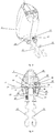
Fig. 1 shows a cross-section of a ready-to-work mixer. -
Fig. 2 shows an ejector of the mixer and correct working members fastened in the spindles (not visible in the figure), -
Fig. 3 shows the mixer in a bottom view, mounted with its working members properly fastened, -
Fig. 4 shows a cross-section of the mixer with a visible ejector, wherein the working members are incorrectly swapped. - The hand-held electric mixer, shown in
Figs. 1 - 3 , provided with thehousing 1, which includes a drive unit consisting of an electric motor (not shown) and a gear unit, which includes twospindles fastening elements mounting plane 21 and toothed rings, which allow transmitting the torque from the motor shaft (not shown) to the workingmembers housing 1 also includes mounted inside anejector 26, which is positioned vertically in relation to its longitudinal axis, which at one end has a button and at the opposite end has a workingsurface 35 consisting of its first 27 and second 28 part that have different heights with respect to themounting plane 21. Theejector 26 has anelongated projection 34, along its longitudinal axis, the face of which forms thesecond part 28 of theworking surface 35. The height, h1 is approximately two times greater than the height, h2. The workingmembers members members shanks lugs 36. Theshank 15 is longer than theshank 16, within their part from thelugs 36, to theirends members lugs 36 held in place byfastening elements shank 15, within its part from thelugs 36 to itsend 29, is smaller than the height h1 and greater than the height h2. While the length of theshank 16, within its part from thelugs 36 to itsend 30, is smaller than the height h2. The distances between theworking surface 35 and theend 29 and theend 30 are approximately equal. This favours the workingmembers ejector 26, it is moved towards the workingmembers first part 27 andsecond part 28 of theworking surface 35 making them unlocked and putting them out of thespindles spring 40 retracts theejector 26 to its starting position. The workingmember 12 is provided with aring 13 integrated with a toothed rim to drive auxiliaries. Thehousing 1 has twoopenings members ring 13 is smaller than the diameter of the opening 22 and greater than the diameter of the opening 23. Thering 13 is housed inside the opening 22. -
Fig. 4 shows the hand-held mixer, the workingmembers member 12 is placed in thespindle 31, and the first workingmember 11 is placed in thespindle 32. In this case, thering 13 of the second workingmember 12 abuts against the housing, since its diameter is greater than the diameter of theopening 23, which causes itslugs 36 do not engage with thefastening element 24 with the result that the second workingmember 12 is not fixedly fastened in thespindle 31. As well as theend 30 of theshank 15 of the first workingmember 11, abuts against thesecond part 28 of the workingsurface 35, because the height h2 is smaller than the length of theshank 15 from thelugs 36 to theend 29, which causes thelugs 36 of the first workingmember 11 not to reach thefastening element 25. As a result of which the first workingmember 11 is not fixedly fastened in thespindle 32. - The present invention relates to a hand-held electric mixer, provided with working members detached by means of an ejector. The invention solves the problem of securing the mixer against its operation with its working members swapped. Different heights of the working surface of the ejector and different lengths of the working member shanks prevent the working members from accidental swapping by the user. In the case of an incorrect working member being inserted in a spindle, the member will not be fixedly fastened due to the fact that the shank of this working member will be blocked by the working surface of the ejector, thereby making the lugs on the working member shank not being engaged with the fastening element of the spindle, and the working member will not be locked.
-
- 1
- - housing
- 11
- - first working member
- 12
- - second working member
- 13
- - ring
- 15, 16
- - shanks
- 21
- - mounting plane
- 22, 23
- - housing openings
- 24, 25
- - fastening elements
- 26
- - ejector
- 27
- - first part of working surface
- 28
- - second part of working surface
- 29, 30
- - shank ends of working members
- 31, 32
- - spindles
- 34
- - longitudinal projection
- 35
- - working surface
- 36
- - lug
- h1
- - height of a first working member
- h2
- - height of a second working member
Claims (11)
- A hand-held mixer adapted to drive a first working member (11) and a second working member (12) by included in a housing (1) spindles (31, 32), having a fastening elements (24, 25), which define a mounting plane (21), provided with an ejector (26), which can apply an axial force with a first part (27) and a second part (28) of a working surface (35) on shank ends (29, 30), of the first working member (11) and the second working member (12) to unlock them from the fastening elements (24, 25), characterized in that a height (h1) of the first part (27) and a height (h2) of the second part (28) with respect to the mounting plane (21) are different.
- A mixer according to claim 1, characterized in that the ejector (26) has at least one elongated projection (34) along its longitudinal axis, the apex of which defines the first part (27) and/or the second part (28) of the working surface (35).
- A mixer according to claim 1 or 2, characterized in that the working surface (35) of the ejector (26) forms a plane, which is inclined obliquely to its longitudinal axis.
- A mixer according to any one of the preceding claims, characterized in that the lengths of shanks (15, 16) within the part from lugs (36) to the shank ends (29, 30) of the working members (11, 12) are different.
- A mixer according to any one of the preceding claims, characterized in that when the working members (11, 12) are fixedly fastened in the spindles (31,32) by fastening elements (24, 25), the distances between the ends (29, 30) of the first working member (11) and the second working member (12), respectively, and the working surface (35) are approximately equal.
- A mixer according to any one of the preceding claims, characterized in that included in the housing (1) and arranged coaxially against the spindles (31, 32), openings (23,22), which allow positioning the working members (11, 12) into the spindles (31, 32), have different diameters.
- A mixer according to any one of the preceding claims, characterized in that at least one of the working members (11, 12) is provided with a ring (13).
- A mixer according to claim 7 characterized in that the ring (13) positioned on the shank (16) at such a distance from the shank end (29, 30), that in a case where the working members (11, 12) are fixedly fastened in the spindles (31, 32), the ring (13) is flush with the corresponding opening (23) or (22).
- A mixer according to claims 7 or 8, characterized in that the diameter of the ring (13) is greater than the smaller diameter of one of the openings (23, 22) and smaller than the larger diameter of the other opening (23, 22).
- A mixer according to claims 7 to 9, characterized in that the ring (13) is made of metal or plastic.
- A mixer according to claims 7 to 10, characterized in that the ring (13) is integrated with a toothed wheel driving other mixer auxiliaries.
Priority Applications (5)
| Application Number | Priority Date | Filing Date | Title |
|---|---|---|---|
| EP16199760.6A EP3323328B1 (en) | 2016-11-21 | 2016-11-21 | Hand-held electric mixer |
| PL16199760.6T PL3323328T3 (en) | 2016-11-21 | 2016-11-21 | Hand-held electric mixer |
| PCT/EP2017/078010 WO2018091272A1 (en) | 2016-11-21 | 2017-11-02 | Hand-held electric mixer |
| PL17792082T PL3541254T3 (en) | 2016-11-21 | 2017-11-02 | Hand-held electric mixer |
| EP17792082.4A EP3541254B1 (en) | 2016-11-21 | 2017-11-02 | Hand-held electric mixer |
Applications Claiming Priority (1)
| Application Number | Priority Date | Filing Date | Title |
|---|---|---|---|
| EP16199760.6A EP3323328B1 (en) | 2016-11-21 | 2016-11-21 | Hand-held electric mixer |
Publications (2)
| Publication Number | Publication Date |
|---|---|
| EP3323328A1 true EP3323328A1 (en) | 2018-05-23 |
| EP3323328B1 EP3323328B1 (en) | 2023-09-06 |
Family
ID=57389257
Family Applications (1)
| Application Number | Title | Priority Date | Filing Date |
|---|---|---|---|
| EP16199760.6A Active EP3323328B1 (en) | 2016-11-21 | 2016-11-21 | Hand-held electric mixer |
Country Status (2)
| Country | Link |
|---|---|
| EP (1) | EP3323328B1 (en) |
| PL (1) | PL3323328T3 (en) |
Cited By (4)
| Publication number | Priority date | Publication date | Assignee | Title |
|---|---|---|---|---|
| CN112806872A (en) * | 2019-11-18 | 2021-05-18 | 汉美驰品牌有限公司 | Agitator for agitator having blades with continuous surfaces |
| US20210145216A1 (en) * | 2019-11-18 | 2021-05-20 | Hamilton Beach Brands, Inc. | Beaters for Mixer with Blades with Continuous Surfaces |
| EP4327708A1 (en) * | 2022-08-25 | 2024-02-28 | Versuni Holding B.V. | Handheld kitchen appliance with ergonomic tool ejection |
| WO2024042139A1 (en) * | 2022-08-25 | 2024-02-29 | Versuni Holding B.V. | Handheld kitchen appliance with ergonomic tool ejection |
Citations (7)
| Publication number | Priority date | Publication date | Assignee | Title |
|---|---|---|---|---|
| US2515755A (en) | 1949-09-29 | 1950-07-18 | Dormeyer Corp | Beater ejector |
| US2797901A (en) * | 1956-01-16 | 1957-07-02 | Scovill Manufacturing Co | Ejector for disconnecting tool shafts from motor driven power unit |
| US3275051A (en) * | 1963-01-10 | 1966-09-27 | Sunbeam Corp | Juice extractor attachment for mixer |
| US3619754A (en) | 1969-09-19 | 1971-11-09 | Wyck International Corp Van | Multifunctional electric home appliance |
| DE2043610A1 (en) * | 1970-09-03 | 1972-03-09 | Krups Fa Robert | Hand mixer with electric motor drive |
| DE29604731U1 (en) * | 1996-03-14 | 1996-06-13 | EGS Elektro- und Hausgerätewerk Suhl GmbH, 98527 Suhl | Device for activating and deactivating the switching and ejector function on electrical household appliances |
| EP0748605A1 (en) * | 1995-06-13 | 1996-12-18 | Ole Bodtcher-Hansen A/S | A household mixing appliance |
-
2016
- 2016-11-21 PL PL16199760.6T patent/PL3323328T3/en unknown
- 2016-11-21 EP EP16199760.6A patent/EP3323328B1/en active Active
Patent Citations (7)
| Publication number | Priority date | Publication date | Assignee | Title |
|---|---|---|---|---|
| US2515755A (en) | 1949-09-29 | 1950-07-18 | Dormeyer Corp | Beater ejector |
| US2797901A (en) * | 1956-01-16 | 1957-07-02 | Scovill Manufacturing Co | Ejector for disconnecting tool shafts from motor driven power unit |
| US3275051A (en) * | 1963-01-10 | 1966-09-27 | Sunbeam Corp | Juice extractor attachment for mixer |
| US3619754A (en) | 1969-09-19 | 1971-11-09 | Wyck International Corp Van | Multifunctional electric home appliance |
| DE2043610A1 (en) * | 1970-09-03 | 1972-03-09 | Krups Fa Robert | Hand mixer with electric motor drive |
| EP0748605A1 (en) * | 1995-06-13 | 1996-12-18 | Ole Bodtcher-Hansen A/S | A household mixing appliance |
| DE29604731U1 (en) * | 1996-03-14 | 1996-06-13 | EGS Elektro- und Hausgerätewerk Suhl GmbH, 98527 Suhl | Device for activating and deactivating the switching and ejector function on electrical household appliances |
Cited By (4)
| Publication number | Priority date | Publication date | Assignee | Title |
|---|---|---|---|---|
| CN112806872A (en) * | 2019-11-18 | 2021-05-18 | 汉美驰品牌有限公司 | Agitator for agitator having blades with continuous surfaces |
| US20210145216A1 (en) * | 2019-11-18 | 2021-05-20 | Hamilton Beach Brands, Inc. | Beaters for Mixer with Blades with Continuous Surfaces |
| EP4327708A1 (en) * | 2022-08-25 | 2024-02-28 | Versuni Holding B.V. | Handheld kitchen appliance with ergonomic tool ejection |
| WO2024042139A1 (en) * | 2022-08-25 | 2024-02-29 | Versuni Holding B.V. | Handheld kitchen appliance with ergonomic tool ejection |
Also Published As
| Publication number | Publication date |
|---|---|
| PL3323328T3 (en) | 2024-02-19 |
| EP3323328B1 (en) | 2023-09-06 |
Similar Documents
| Publication | Publication Date | Title |
|---|---|---|
| EP3323328B1 (en) | Hand-held electric mixer | |
| US10799070B2 (en) | Mixing tool lock for a kitchen appliance | |
| US9193045B2 (en) | Tool attachment | |
| EP3925571B1 (en) | Brush head for electric toothbrush | |
| CN102514021B (en) | Food cutting accessories with improved discharge and electrical appliance including such accessories | |
| CN102961063B (en) | Lid and food processor for food processor | |
| CN201436959U (en) | Stirrer and mixing equipment provided with same | |
| EP1262131A1 (en) | Attachment mechanism | |
| CN107713823B (en) | Food processing device and bowl assembly and stirring blade assembly thereof | |
| CN102256519A (en) | Release system for kitchen utensil | |
| JP2003530229A (en) | Grinding machine tool mounting part | |
| US20150321305A1 (en) | Tool attachment and tool system | |
| EP1853833B1 (en) | Mixer, mixing implement and associated attachment mechanism | |
| US20080223225A1 (en) | Spoon food mixer | |
| EP3541254B1 (en) | Hand-held electric mixer | |
| CN111230813A (en) | Hand-held power tool system and tool attachment | |
| CN208435401U (en) | Food cooking machine | |
| JP5747568B2 (en) | Electric rotating device for cooking | |
| EP3960046B1 (en) | Rotator, rotation assembly, container, and food processor | |
| MXPA02005307A (en) | Attachment mechanism. | |
| EP2810704B1 (en) | Agitator for mixing liquid samples in micro- and millilitre reaction vessels | |
| US4620796A (en) | Electric mixer with beater eject mechanism | |
| CN210990372U (en) | Ultrasonic micro-probe connector | |
| EP3427619B1 (en) | Tool detaching means for kitchen appliances | |
| EP4327708A1 (en) | Handheld kitchen appliance with ergonomic tool ejection |
Legal Events
| Date | Code | Title | Description |
|---|---|---|---|
| PUAI | Public reference made under article 153(3) epc to a published international application that has entered the european phase |
Free format text: ORIGINAL CODE: 0009012 |
|
| STAA | Information on the status of an ep patent application or granted ep patent |
Free format text: STATUS: THE APPLICATION HAS BEEN PUBLISHED |
|
| AK | Designated contracting states |
Kind code of ref document: A1 Designated state(s): AL AT BE BG CH CY CZ DE DK EE ES FI FR GB GR HR HU IE IS IT LI LT LU LV MC MK MT NL NO PL PT RO RS SE SI SK SM TR |
|
| AX | Request for extension of the european patent |
Extension state: BA ME |
|
| STAA | Information on the status of an ep patent application or granted ep patent |
Free format text: STATUS: REQUEST FOR EXAMINATION WAS MADE |
|
| 17P | Request for examination filed |
Effective date: 20181123 |
|
| RBV | Designated contracting states (corrected) |
Designated state(s): AL AT BE BG CH CY CZ DE DK EE ES FI FR GB GR HR HU IE IS IT LI LT LU LV MC MK MT NL NO PL PT RO RS SE SI SK SM TR |
|
| STAA | Information on the status of an ep patent application or granted ep patent |
Free format text: STATUS: EXAMINATION IS IN PROGRESS |
|
| 17Q | First examination report despatched |
Effective date: 20220217 |
|
| GRAP | Despatch of communication of intention to grant a patent |
Free format text: ORIGINAL CODE: EPIDOSNIGR1 |
|
| STAA | Information on the status of an ep patent application or granted ep patent |
Free format text: STATUS: GRANT OF PATENT IS INTENDED |
|
| INTG | Intention to grant announced |
Effective date: 20221214 |
|
| GRAJ | Information related to disapproval of communication of intention to grant by the applicant or resumption of examination proceedings by the epo deleted |
Free format text: ORIGINAL CODE: EPIDOSDIGR1 |
|
| STAA | Information on the status of an ep patent application or granted ep patent |
Free format text: STATUS: EXAMINATION IS IN PROGRESS |
|
| GRAP | Despatch of communication of intention to grant a patent |
Free format text: ORIGINAL CODE: EPIDOSNIGR1 |
|
| STAA | Information on the status of an ep patent application or granted ep patent |
Free format text: STATUS: GRANT OF PATENT IS INTENDED |
|
| INTC | Intention to grant announced (deleted) | ||
| INTG | Intention to grant announced |
Effective date: 20230508 |
|
| GRAS | Grant fee paid |
Free format text: ORIGINAL CODE: EPIDOSNIGR3 |
|
| GRAA | (expected) grant |
Free format text: ORIGINAL CODE: 0009210 |
|
| STAA | Information on the status of an ep patent application or granted ep patent |
Free format text: STATUS: THE PATENT HAS BEEN GRANTED |
|
| AK | Designated contracting states |
Kind code of ref document: B1 Designated state(s): AL AT BE BG CH CY CZ DE DK EE ES FI FR GB GR HR HU IE IS IT LI LT LU LV MC MK MT NL NO PL PT RO RS SE SI SK SM TR |
|
| REG | Reference to a national code |
Ref country code: GB Ref legal event code: FG4D |
|
| REG | Reference to a national code |
Ref country code: CH Ref legal event code: EP |
|
| REG | Reference to a national code |
Ref country code: IE Ref legal event code: FG4D |
|
| REG | Reference to a national code |
Ref country code: DE Ref legal event code: R096 Ref document number: 602016082492 Country of ref document: DE |
|
| REG | Reference to a national code |
Ref country code: LT Ref legal event code: MG9D |
|
| REG | Reference to a national code |
Ref country code: NL Ref legal event code: MP Effective date: 20230906 |
|
| PG25 | Lapsed in a contracting state [announced via postgrant information from national office to epo] |
Ref country code: GR Free format text: LAPSE BECAUSE OF FAILURE TO SUBMIT A TRANSLATION OF THE DESCRIPTION OR TO PAY THE FEE WITHIN THE PRESCRIBED TIME-LIMIT Effective date: 20231207 |
|
| PG25 | Lapsed in a contracting state [announced via postgrant information from national office to epo] |
Ref country code: SE Free format text: LAPSE BECAUSE OF FAILURE TO SUBMIT A TRANSLATION OF THE DESCRIPTION OR TO PAY THE FEE WITHIN THE PRESCRIBED TIME-LIMIT Effective date: 20230906 Ref country code: RS Free format text: LAPSE BECAUSE OF FAILURE TO SUBMIT A TRANSLATION OF THE DESCRIPTION OR TO PAY THE FEE WITHIN THE PRESCRIBED TIME-LIMIT Effective date: 20230906 Ref country code: NO Free format text: LAPSE BECAUSE OF FAILURE TO SUBMIT A TRANSLATION OF THE DESCRIPTION OR TO PAY THE FEE WITHIN THE PRESCRIBED TIME-LIMIT Effective date: 20231206 Ref country code: LV Free format text: LAPSE BECAUSE OF FAILURE TO SUBMIT A TRANSLATION OF THE DESCRIPTION OR TO PAY THE FEE WITHIN THE PRESCRIBED TIME-LIMIT Effective date: 20230906 Ref country code: LT Free format text: LAPSE BECAUSE OF FAILURE TO SUBMIT A TRANSLATION OF THE DESCRIPTION OR TO PAY THE FEE WITHIN THE PRESCRIBED TIME-LIMIT Effective date: 20230906 Ref country code: HR Free format text: LAPSE BECAUSE OF FAILURE TO SUBMIT A TRANSLATION OF THE DESCRIPTION OR TO PAY THE FEE WITHIN THE PRESCRIBED TIME-LIMIT Effective date: 20230906 Ref country code: GR Free format text: LAPSE BECAUSE OF FAILURE TO SUBMIT A TRANSLATION OF THE DESCRIPTION OR TO PAY THE FEE WITHIN THE PRESCRIBED TIME-LIMIT Effective date: 20231207 Ref country code: FI Free format text: LAPSE BECAUSE OF FAILURE TO SUBMIT A TRANSLATION OF THE DESCRIPTION OR TO PAY THE FEE WITHIN THE PRESCRIBED TIME-LIMIT Effective date: 20230906 |
|
| REG | Reference to a national code |
Ref country code: AT Ref legal event code: MK05 Ref document number: 1607345 Country of ref document: AT Kind code of ref document: T Effective date: 20230906 |
|
| PG25 | Lapsed in a contracting state [announced via postgrant information from national office to epo] |
Ref country code: NL Free format text: LAPSE BECAUSE OF FAILURE TO SUBMIT A TRANSLATION OF THE DESCRIPTION OR TO PAY THE FEE WITHIN THE PRESCRIBED TIME-LIMIT Effective date: 20230906 |
|
| PG25 | Lapsed in a contracting state [announced via postgrant information from national office to epo] |
Ref country code: IS Free format text: LAPSE BECAUSE OF FAILURE TO SUBMIT A TRANSLATION OF THE DESCRIPTION OR TO PAY THE FEE WITHIN THE PRESCRIBED TIME-LIMIT Effective date: 20240106 |
|
| PG25 | Lapsed in a contracting state [announced via postgrant information from national office to epo] |
Ref country code: AT Free format text: LAPSE BECAUSE OF FAILURE TO SUBMIT A TRANSLATION OF THE DESCRIPTION OR TO PAY THE FEE WITHIN THE PRESCRIBED TIME-LIMIT Effective date: 20230906 |
|
| PG25 | Lapsed in a contracting state [announced via postgrant information from national office to epo] |
Ref country code: ES Free format text: LAPSE BECAUSE OF FAILURE TO SUBMIT A TRANSLATION OF THE DESCRIPTION OR TO PAY THE FEE WITHIN THE PRESCRIBED TIME-LIMIT Effective date: 20230906 |
|
| PG25 | Lapsed in a contracting state [announced via postgrant information from national office to epo] |
Ref country code: SM Free format text: LAPSE BECAUSE OF FAILURE TO SUBMIT A TRANSLATION OF THE DESCRIPTION OR TO PAY THE FEE WITHIN THE PRESCRIBED TIME-LIMIT Effective date: 20230906 Ref country code: RO Free format text: LAPSE BECAUSE OF FAILURE TO SUBMIT A TRANSLATION OF THE DESCRIPTION OR TO PAY THE FEE WITHIN THE PRESCRIBED TIME-LIMIT Effective date: 20230906 Ref country code: IS Free format text: LAPSE BECAUSE OF FAILURE TO SUBMIT A TRANSLATION OF THE DESCRIPTION OR TO PAY THE FEE WITHIN THE PRESCRIBED TIME-LIMIT Effective date: 20240106 Ref country code: ES Free format text: LAPSE BECAUSE OF FAILURE TO SUBMIT A TRANSLATION OF THE DESCRIPTION OR TO PAY THE FEE WITHIN THE PRESCRIBED TIME-LIMIT Effective date: 20230906 Ref country code: EE Free format text: LAPSE BECAUSE OF FAILURE TO SUBMIT A TRANSLATION OF THE DESCRIPTION OR TO PAY THE FEE WITHIN THE PRESCRIBED TIME-LIMIT Effective date: 20230906 Ref country code: CZ Free format text: LAPSE BECAUSE OF FAILURE TO SUBMIT A TRANSLATION OF THE DESCRIPTION OR TO PAY THE FEE WITHIN THE PRESCRIBED TIME-LIMIT Effective date: 20230906 Ref country code: AT Free format text: LAPSE BECAUSE OF FAILURE TO SUBMIT A TRANSLATION OF THE DESCRIPTION OR TO PAY THE FEE WITHIN THE PRESCRIBED TIME-LIMIT Effective date: 20230906 Ref country code: SK Free format text: LAPSE BECAUSE OF FAILURE TO SUBMIT A TRANSLATION OF THE DESCRIPTION OR TO PAY THE FEE WITHIN THE PRESCRIBED TIME-LIMIT Effective date: 20230906 Ref country code: PT Free format text: LAPSE BECAUSE OF FAILURE TO SUBMIT A TRANSLATION OF THE DESCRIPTION OR TO PAY THE FEE WITHIN THE PRESCRIBED TIME-LIMIT Effective date: 20240108 |
|
| PG25 | Lapsed in a contracting state [announced via postgrant information from national office to epo] |
Ref country code: IT Free format text: LAPSE BECAUSE OF FAILURE TO SUBMIT A TRANSLATION OF THE DESCRIPTION OR TO PAY THE FEE WITHIN THE PRESCRIBED TIME-LIMIT Effective date: 20230906 |
|
| REG | Reference to a national code |
Ref country code: DE Ref legal event code: R119 Ref document number: 602016082492 Country of ref document: DE |
|
| REG | Reference to a national code |
Ref country code: CH Ref legal event code: PL |
|
| PG25 | Lapsed in a contracting state [announced via postgrant information from national office to epo] |
Ref country code: MC Free format text: LAPSE BECAUSE OF FAILURE TO SUBMIT A TRANSLATION OF THE DESCRIPTION OR TO PAY THE FEE WITHIN THE PRESCRIBED TIME-LIMIT Effective date: 20230906 |
|
| PG25 | Lapsed in a contracting state [announced via postgrant information from national office to epo] |
Ref country code: DK Free format text: LAPSE BECAUSE OF FAILURE TO SUBMIT A TRANSLATION OF THE DESCRIPTION OR TO PAY THE FEE WITHIN THE PRESCRIBED TIME-LIMIT Effective date: 20230906 |
|
| PLBE | No opposition filed within time limit |
Free format text: ORIGINAL CODE: 0009261 |
|
| STAA | Information on the status of an ep patent application or granted ep patent |
Free format text: STATUS: NO OPPOSITION FILED WITHIN TIME LIMIT |
|
| PG25 | Lapsed in a contracting state [announced via postgrant information from national office to epo] |
Ref country code: LU Free format text: LAPSE BECAUSE OF NON-PAYMENT OF DUE FEES Effective date: 20231121 |
|
| PG25 | Lapsed in a contracting state [announced via postgrant information from national office to epo] |
Ref country code: CH Free format text: LAPSE BECAUSE OF NON-PAYMENT OF DUE FEES Effective date: 20231130 |
|
| PG25 | Lapsed in a contracting state [announced via postgrant information from national office to epo] |
Ref country code: MC Free format text: LAPSE BECAUSE OF FAILURE TO SUBMIT A TRANSLATION OF THE DESCRIPTION OR TO PAY THE FEE WITHIN THE PRESCRIBED TIME-LIMIT Effective date: 20230906 Ref country code: LU Free format text: LAPSE BECAUSE OF NON-PAYMENT OF DUE FEES Effective date: 20231121 Ref country code: DK Free format text: LAPSE BECAUSE OF FAILURE TO SUBMIT A TRANSLATION OF THE DESCRIPTION OR TO PAY THE FEE WITHIN THE PRESCRIBED TIME-LIMIT Effective date: 20230906 Ref country code: CH Free format text: LAPSE BECAUSE OF NON-PAYMENT OF DUE FEES Effective date: 20231130 Ref country code: SI Free format text: LAPSE BECAUSE OF FAILURE TO SUBMIT A TRANSLATION OF THE DESCRIPTION OR TO PAY THE FEE WITHIN THE PRESCRIBED TIME-LIMIT Effective date: 20230906 |
|
| REG | Reference to a national code |
Ref country code: BE Ref legal event code: MM Effective date: 20231130 |
|
| 26N | No opposition filed |
Effective date: 20240607 |
|
| GBPC | Gb: european patent ceased through non-payment of renewal fee |
Effective date: 20231206 |
|
| REG | Reference to a national code |
Ref country code: IE Ref legal event code: MM4A |
|
| PG25 | Lapsed in a contracting state [announced via postgrant information from national office to epo] |
Ref country code: DE Free format text: LAPSE BECAUSE OF NON-PAYMENT OF DUE FEES Effective date: 20240601 Ref country code: IE Free format text: LAPSE BECAUSE OF NON-PAYMENT OF DUE FEES Effective date: 20231121 |
|
| PG25 | Lapsed in a contracting state [announced via postgrant information from national office to epo] |
Ref country code: GB Free format text: LAPSE BECAUSE OF NON-PAYMENT OF DUE FEES Effective date: 20231206 |
|
| PG25 | Lapsed in a contracting state [announced via postgrant information from national office to epo] |
Ref country code: BE Free format text: LAPSE BECAUSE OF NON-PAYMENT OF DUE FEES Effective date: 20231130 |
|
| PG25 | Lapsed in a contracting state [announced via postgrant information from national office to epo] |
Ref country code: FR Free format text: LAPSE BECAUSE OF NON-PAYMENT OF DUE FEES Effective date: 20231130 |
|
| PG25 | Lapsed in a contracting state [announced via postgrant information from national office to epo] |
Ref country code: IE Free format text: LAPSE BECAUSE OF NON-PAYMENT OF DUE FEES Effective date: 20231121 Ref country code: GB Free format text: LAPSE BECAUSE OF NON-PAYMENT OF DUE FEES Effective date: 20231206 Ref country code: FR Free format text: LAPSE BECAUSE OF NON-PAYMENT OF DUE FEES Effective date: 20231130 Ref country code: DE Free format text: LAPSE BECAUSE OF NON-PAYMENT OF DUE FEES Effective date: 20240601 Ref country code: BE Free format text: LAPSE BECAUSE OF NON-PAYMENT OF DUE FEES Effective date: 20231130 |
|
| PG25 | Lapsed in a contracting state [announced via postgrant information from national office to epo] |
Ref country code: BG Free format text: LAPSE BECAUSE OF FAILURE TO SUBMIT A TRANSLATION OF THE DESCRIPTION OR TO PAY THE FEE WITHIN THE PRESCRIBED TIME-LIMIT Effective date: 20230906 |
|
| PG25 | Lapsed in a contracting state [announced via postgrant information from national office to epo] |
Ref country code: BG Free format text: LAPSE BECAUSE OF FAILURE TO SUBMIT A TRANSLATION OF THE DESCRIPTION OR TO PAY THE FEE WITHIN THE PRESCRIBED TIME-LIMIT Effective date: 20230906 |
|
| PG25 | Lapsed in a contracting state [announced via postgrant information from national office to epo] |
Ref country code: CY Free format text: LAPSE BECAUSE OF FAILURE TO SUBMIT A TRANSLATION OF THE DESCRIPTION OR TO PAY THE FEE WITHIN THE PRESCRIBED TIME-LIMIT; INVALID AB INITIO Effective date: 20161121 |
|
| PG25 | Lapsed in a contracting state [announced via postgrant information from national office to epo] |
Ref country code: HU Free format text: LAPSE BECAUSE OF FAILURE TO SUBMIT A TRANSLATION OF THE DESCRIPTION OR TO PAY THE FEE WITHIN THE PRESCRIBED TIME-LIMIT; INVALID AB INITIO Effective date: 20161121 |
|
| PG25 | Lapsed in a contracting state [announced via postgrant information from national office to epo] |
Ref country code: TR Free format text: LAPSE BECAUSE OF FAILURE TO SUBMIT A TRANSLATION OF THE DESCRIPTION OR TO PAY THE FEE WITHIN THE PRESCRIBED TIME-LIMIT Effective date: 20230906 |
|
| PGFP | Annual fee paid to national office [announced via postgrant information from national office to epo] |
Ref country code: PL Payment date: 20251114 Year of fee payment: 10 |