EP3322964B1 - Load cell having an overload protection - Google Patents
Load cell having an overload protection Download PDFInfo
- Publication number
- EP3322964B1 EP3322964B1 EP16741266.7A EP16741266A EP3322964B1 EP 3322964 B1 EP3322964 B1 EP 3322964B1 EP 16741266 A EP16741266 A EP 16741266A EP 3322964 B1 EP3322964 B1 EP 3322964B1
- Authority
- EP
- European Patent Office
- Prior art keywords
- load
- load cell
- parallel guiding
- mounting portion
- extending
- Prior art date
- Legal status (The legal status is an assumption and is not a legal conclusion. Google has not performed a legal analysis and makes no representation as to the accuracy of the status listed.)
- Active
Links
Images


Classifications
-
- G—PHYSICS
- G01—MEASURING; TESTING
- G01G—WEIGHING
- G01G23/00—Auxiliary devices for weighing apparatus
- G01G23/005—Means for preventing overload
Definitions
- the invention relates to a load cell having an overload protection and an electronic balance with a load cell having an overload protection.
- US 4'574'898 discloses a load cell with an overload protection, the load cell comprises a load-receiver member, a main member and a load-transmitting member connecting the load-receiver member to the main member. Because the load-transmitting member comprises some separate parts, the assembling increases work and cost of the product.
- EP 1'912'048 A1 relates to an overload block for a load cell, comprising a force introduction element for force-effective connection with a load, and a force discharge element for force-effective connection with a load cell, wherein between the force application element and the force discharge element a free space is arranged and the force introduction element is movable relative to the force discharge element.
- the object of this invention is to provide a load cell and an electronic balance that has simple structure, is easy to assemble and has an overload protection.
- a load cell comprises a load receiving member, a main member and a load transmitting member and a stop portion.
- the main member comprises a movable portion, a fixed portion and a parallel guiding member for connecting the fixed portion and the movable portion.
- the load transmitting member comprises a first mounting portion for mounting the load receiving member, a second mounting portion for mounting the movable portion and a parallel guiding member for connecting the first mounting portion to the second mounting portion.
- the first mounting portion is movable vertically relative to the second mounting portion when a load being applied on the first mounting portion and the load transmitting member is a single piece.
- the load cell further comprises a stop portion for preventing the first mounting portion from further moving downwardly for overload protection wherein the fixed portion comprises an end portion and an extending portion extending forwardly from the end portion and wherein the extending portion being the stop portion.
- relative directions refer to a load cell when used in mode for operation, wherein the forward direction is defined as the direction from the fixed portion to the movable portion, the vertical direction is defined as the direction that is perpendicular to the forward direction and essentially parallel to applied load, wherein the upward direction in the vertical direction is defined as the direction from a plane that is closer to the ground where on which the load cell is mounted to a plane that is more distant from the latter plane.
- the invention provides a load cell.
- the load cell comprises a load receiving member 1, a main member 3, a load transmitting member 2 and a stop portion.
- the load receiving member 1 comprises a base portion 11 and a cylindrical connecting portion 12 extending downwardly from the base portion 11.
- the main member 3, 3' comprises a movable portion 31, 31', a fixed portion 32, 32' and a first parallel guiding member 33 for connecting the fixed portion 32, 32' to the movable portion 31, 31'.
- the first parallel guiding member 33 comprises a first upper parallel guiding plate 331, 331' and a first lower parallel guiding plate 332. Slots extending in the transverse direction are formed in the first guiding member 3, 3'. The slots are arc-shaped or square-shaped. In this embodiment, the slots are disposed at the two ends of the first upper parallel guiding member 331 and the first low parallel guiding plate 332.
- the load transmitting member 2, 2' comprises a first mounting portion 21, 21' for mounting the load receiving member 1, 1', a second mounting portion 22, 22' for mounting the movable portion 31, 31' and a parallel guiding connection member 24, 24' for connecting the first mounting portion 21, 21' to the second mounting portion 22, 22'.
- the connection portion 12 is mounted to the first mounting portion 21, 21' for transmitting the force applied on the load receiving member 1, 1' to the load transmitting member 2, 2'.
- the load transmitting member 2, 2' is a single piece for having a simple structure and being easily assembled.
- the load transmitting member 2, 2' can be made by die-cast moulding, by machining or by both of them.
- the load transmitting member 2 is set above the main member 31, 32, 33 and extends in the X direction so that the load cell has a compact structure.
- the fixed portion 32 comprises an end portion 321, an extending portion 322 extending forwardly from the end portion 321 and the supporting portions (323, 324) extending forwardly from the extending portion 322.
- the supporting portions comprise a first supporting portion 323 and a second supporting portion 324.
- the extending portion 322 defines a first upper surface 3221 extending horizontally and an upper surface 3222 lower than the first upper surface 3221 extending horizontally. In other embodiment, the first upper surface 3221 and the upper surface 3222 can be in the same plane.
- the extending portion 322 is a stop portion.
- the bottom surface of the first mounting portion 21 abuts to the upper surface 322 for overload protection.
- At least a portion of the movable portion 31 is disposed in the space formed between the first supporting portion 323 and the second supporting portion 324.
- a second through hole 23 extending downwardly from the upper surface 26 of the load transmitting member 2 between the first mounting portion 21 and the second mounting portion 22, so that the load receiving member 2 has a smaller weight and the rigidity of the load-receiver member 2 is lower.
- the parallel guiding connection member 24 comprises an upper parallel guiding connection plate 241 and a lower parallel guiding connection plate 242.
- a first through hole 243 extending horizontally in the transverse direction is formed between the upper parallel guiding connection plate 241 and the lower parallel guiding connection plate 242.
- the first through hole 243 is "H" shaped.
- the upper parallel guiding connection plate 241 comprises a fist slot 2411 and a second slot 2412.
- the lower parallel guiding connection plate 242 comprises a third slot 2421 corresponding to the first slot 2411 and a forth slot 2422 corresponding to the second slot 2412.
- the first mounting portion 21 can only move in the vertically downwarded direction, so that the force of the center load and eccentric load is closer to each other. This can prevent the load cell from introducing an eccentric load into the movable member.
- the load transmitting member 2 comprises a third through hole 27 extending in the X direction whereby the third through hole 27 has an opening facing downwardly.
- the first mounting portion 21, 21' comprises protruding portions 25, 25' extending vertically and downwardly.
- the first mounting portion 21, 21' moves downwardly.
- the first mounting portion 21, 21' can only produce a vertical downward displacement because of effect of the parallel guiding member 24, 24'.
- the protruding portions 25 abut to the upper surface 3222 for overload protection.
- the movable portion 31 comprises a body portion 311 and an attaching portion 312 extending upwardly from the body portion 311.
- the load transmitting member 2 is mounted on the attaching portion 312 and at least a portion of the attaching portion 312 is disposed in the third through hole 27, so that the load cell can have a small volume.
- the figure 7 and figure 9 illustrate another embodiment of this invention.
- the load transmitting member 2' comprises a first mounting portion 21' for mounting the load receiving member 1', a second mounting portion 22' and a parallel guiding member 24' for connecting the first mounting portion 21' to the second mounting portion 22'.
- the parallel guiding connection member is divided by the first through hole 243'.
- the first through hole 243' is H shaped.
- the load transmitting member 2' comprises a protruding portion 23' and protruding portions 25' extending downwardly.
- the protruding portion 23' is below the second mounting portion 22' and the protruding portions 25' are disposed on the lower surface of the first mounting portion 21'.
- the protruding portions 25' are protruding on both sides of the first upper parallel guiding plate 331' to the stop portion.
- the protruding portions 23' is to fix the load transmitting member 2' onto the movable portion 31'.
- a distance is formed between the lower surface of the load transmitting member 2' and the upper surface of the main member 3' for vertical displacement of the load transmitting member 2'.
- a pair of protruding posts 33' extends upwardly from the fixed portion 32'.
- the protruding posts 33' are arranged below the protruding portions 25'. When overload is applied on the load receiving member 1', the protruding portions 25' abut on the protruding posts 33' to protect the load cell.
- the protruding posts 33' are square shaped or other shaped.
Landscapes
- Physics & Mathematics (AREA)
- General Physics & Mathematics (AREA)
- Measurement Of Force In General (AREA)
Description
- The invention relates to a load cell having an overload protection and an electronic balance with a load cell having an overload protection.
- In the prior art, during the use or the transport, if there is no overload protection or the overload protection is imperfect, the electronic balance can be easily damaged due to the effects of static or dynamic impact forces. US 4'574'898 discloses a load cell with an overload protection, the load cell comprises a load-receiver member, a main member and a load-transmitting member connecting the load-receiver member to the main member. Because the load-transmitting member comprises some separate parts, the assembling increases work and cost of the product.
- EP 1'912'048 A1 relates to an overload block for a load cell, comprising a force introduction element for force-effective connection with a load, and a force discharge element for force-effective connection with a load cell, wherein between the force application element and the force discharge element a free space is arranged and the force introduction element is movable relative to the force discharge element.
- Hence, it is desired to have a load cell solving the problem above.
- The object of this invention is to provide a load cell and an electronic balance that has simple structure, is easy to assemble and has an overload protection.
- In accordance with the present invention, a load cell comprises a load receiving member, a main member and a load transmitting member and a stop portion. The main member comprises a movable portion, a fixed portion and a parallel guiding member for connecting the fixed portion and the movable portion. The load transmitting member comprises a first mounting portion for mounting the load receiving member, a second mounting portion for mounting the movable portion and a parallel guiding member for connecting the first mounting portion to the second mounting portion. The first mounting portion is movable vertically relative to the second mounting portion when a load being applied on the first mounting portion and the load transmitting member is a single piece. The load cell further comprises a stop portion for preventing the first mounting portion from further moving downwardly for overload protection wherein the fixed portion comprises an end portion and an extending portion extending forwardly from the end portion and wherein the extending portion being the stop portion.
- Other objects, advantages and novel features of the present invention will become more apparent from the following detailed description of the present embodiment when taken in conjunction with the accompanying drawings.
- Details of the load cell according to the invention will be apparent from the description of the embodiments that are illustrated in the drawings, wherein
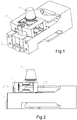
- Fig. 1
- is a perspective view of the load cell according to the present invention;
- Fig. 2
- is a front view of the load cell;
- Fig. 3
- is a sectional view of the load cell;
- Fig. 4
- is an exploded view of the load cell;
- Fig. 5
- is a perspective view of the load transmitting member;
- Fig. 6
- is another perspective view of the load-transmitting member;
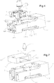
- Fig. 7
- is an exploded view of the load cell according to the second embodiment of the invention;
- Fig. 8
- is a front view of the load cell of
FIG. 7 ; and - Fig. 9
- is a perspective view of the load transmitting member of
FIG. 7 . - Within this description, relative directions refer to a load cell when used in mode for operation, wherein the forward direction is defined as the direction from the fixed portion to the movable portion, the vertical direction is defined as the direction that is perpendicular to the forward direction and essentially parallel to applied load, wherein the upward direction in the vertical direction is defined as the direction from a plane that is closer to the ground where on which the load cell is mounted to a plane that is more distant from the latter plane.
- With reference to
figures 1 to 6 , the invention provides a load cell. The load cell comprises aload receiving member 1, amain member 3, aload transmitting member 2 and a stop portion. - The
load receiving member 1 comprises a base portion 11 and a cylindrical connectingportion 12 extending downwardly from the base portion 11. - The
main member 3, 3' comprises amovable portion 31, 31', a fixedportion 32, 32' and a first parallel guidingmember 33 for connecting the fixedportion 32, 32' to themovable portion 31, 31'. The first parallel guidingmember 33 comprises a first upper parallel guidingplate 331, 331' and a first lower parallel guidingplate 332. Slots extending in the transverse direction are formed in the first guidingmember 3, 3'. The slots are arc-shaped or square-shaped. In this embodiment, the slots are disposed at the two ends of the first upper parallel guidingmember 331 and the first low parallel guidingplate 332. - The
load transmitting member 2, 2' comprises afirst mounting portion 21, 21' for mounting theload receiving member 1, 1', asecond mounting portion 22, 22' for mounting themovable portion 31, 31' and a parallel guidingconnection member 24, 24' for connecting thefirst mounting portion 21, 21' to thesecond mounting portion 22, 22'. Theconnection portion 12 is mounted to thefirst mounting portion 21, 21' for transmitting the force applied on theload receiving member 1, 1' to theload transmitting member 2, 2'. Theload transmitting member 2, 2' is a single piece for having a simple structure and being easily assembled. Theload transmitting member 2, 2' can be made by die-cast moulding, by machining or by both of them. - With reference to
figure 3 , theload transmitting member 2 is set above themain member - With reference to
figure 4 , thefixed portion 32 comprises anend portion 321, an extendingportion 322 extending forwardly from theend portion 321 and the supporting portions (323, 324) extending forwardly from the extendingportion 322. The supporting portions comprise a first supportingportion 323 and a second supportingportion 324. The extendingportion 322 defines a firstupper surface 3221 extending horizontally and anupper surface 3222 lower than the firstupper surface 3221 extending horizontally. In other embodiment, the firstupper surface 3221 and theupper surface 3222 can be in the same plane. - In this embodiment, the
extending portion 322 is a stop portion. When an overload is applied on theload receiving member 1, the bottom surface of thefirst mounting portion 21 abuts to theupper surface 322 for overload protection. At least a portion of themovable portion 31 is disposed in the space formed between the first supportingportion 323 and the second supportingportion 324. - With reference to
figure 5 and tofigure 6 , a second throughhole 23 extending downwardly from theupper surface 26 of theload transmitting member 2 between thefirst mounting portion 21 and thesecond mounting portion 22, so that theload receiving member 2 has a smaller weight and the rigidity of the load-receiver member 2 is lower. - The parallel guiding
connection member 24 comprises an upper parallel guidingconnection plate 241 and a lower parallel guidingconnection plate 242. A first throughhole 243 extending horizontally in the transverse direction is formed between the upper parallel guidingconnection plate 241 and the lower parallel guidingconnection plate 242. The first throughhole 243 is "H" shaped. The upper parallel guidingconnection plate 241 comprises a fist slot 2411 and asecond slot 2412. The lower parallel guidingconnection plate 242 comprises athird slot 2421 corresponding to the first slot 2411 and a forthslot 2422 corresponding to thesecond slot 2412. When a load is applied on theload receiving member 1, the bottom surface of thefirst mounting portion 21 moves downwardly. Because of the parallelguiding connection member 24, no matter of a center load or an eccentric load, the first mountingportion 21 can only move in the vertically downwarded direction, so that the force of the center load and eccentric load is closer to each other. This can prevent the load cell from introducing an eccentric load into the movable member. - The
load transmitting member 2 comprises a third throughhole 27 extending in the X direction whereby the third throughhole 27 has an opening facing downwardly. - In the exemplary embodiment, the first mounting
portion 21, 21' comprises protrudingportions 25, 25' extending vertically and downwardly. When a load is applied on theload receiver member 1, 1', the first mountingportion 21, 21' moves downwardly. The first mountingportion 21, 21' can only produce a vertical downward displacement because of effect of the parallel guidingmember 24, 24'. When the load exceeds the predefined maximum, the protrudingportions 25 abut to theupper surface 3222 for overload protection. - The
movable portion 31 comprises a body portion 311 and an attachingportion 312 extending upwardly from the body portion 311. Theload transmitting member 2 is mounted on the attachingportion 312 and at least a portion of the attachingportion 312 is disposed in the third throughhole 27, so that the load cell can have a small volume. - The
figure 7 andfigure 9 illustrate another embodiment of this invention. The load transmitting member 2' comprises a first mounting portion 21' for mounting the load receiving member 1', a second mounting portion 22' and a parallel guiding member 24' for connecting the first mounting portion 21' to the second mountingportion 22'.The parallel guiding connection member is divided by the first through hole 243'. The first through hole 243' is H shaped. The load transmitting member 2' comprises a protruding portion 23' and protruding portions 25' extending downwardly. The protruding portion 23' is below the second mounting portion 22' and the protruding portions 25' are disposed on the lower surface of the first mounting portion 21'. The protruding portions 25' are protruding on both sides of the first upper parallel guiding plate 331' to the stop portion. The protruding portions 23' is to fix the load transmitting member 2' onto the movable portion 31'. A distance is formed between the lower surface of the load transmitting member 2' and the upper surface of the main member 3' for vertical displacement of the load transmitting member 2'. In the exemplary embodiment, a pair of protruding posts 33' extends upwardly from the fixed portion 32'. The protruding posts 33' are arranged below the protruding portions 25'. When overload is applied on the load receiving member 1', the protruding portions 25' abut on the protruding posts 33' to protect the load cell. The protruding posts 33' are square shaped or other shaped. -
- 1, 1'
- load receiving member
- 2, 2'
- load transmitting member
- 3, 3'
- main member
- 11
- base portion
- 12
- cylindrical connecting portion
- 21, 21'
- first mounting portion
- 22, 22'
- second mounting portion
- 23, 23'
- second through hole
- 24, 24'
- parallel guiding connection member
- 25, 25'
- protruding portions
- 26
- upper surface
- 27
- third through hole
- 31, 31'
- movable portion
- 32, 32'
- fixed portion
- 33
- first parallel guiding member
- 33'
- protruding posts
- 241
- upper parallel guiding connection plate
- 242
- lower parallel guiding connection plate
- 243, 243'
- first through hole
- 311
- body portion
- 312
- attaching portion
- 321
- end portion
- 322
- extending portion
- 323
- first supporting portion
- 324
- second supporting portion
- 331, 331'
- first upper parallel guiding plate
- 332
- first lower parallel guiding plate
- 2411
- fist slot
- 2412
- second slot
- 2421
- third slot
- 2422
- forth slot
- 3221
- first upper surface
- 3222
- upper surface
Claims (9)
- Load cell for an electronic balance, comprisinga load receiving member (1, 1');a main member (3, 3'), the main member (3, 3') comprisinga movable portion (31, 31'),a fixed portion (32, 32') anda parallel guiding member (33) for connecting the fixed portion (32, 32') and the movable portion (31, 31'),wherein the movable portion (31, 31') being movable vertically relative to the fixed portion (32, 32') when a load being applied on the movable portion (31, 31');a load transmitting member (2, 2'), the load transmitting member (2, 2') comprisinga first mounting portion (21, 21') for mounting the load receiving member (1, 1'),a second mounting portion (22, 22') for mounting the load transmitting member (2, 2') to the movable portion (3, 3') anda parallel guiding connection member (24, 24') for connecting the first mounting portion (21, 21') to the second mounting portion (22, 22'),wherein the first mounting portion (21, 21') being movable vertically relative to the second mounting portion (22, 22') when a load being applied on the first mounting portion (21, 21'), andwherein the load transmitting member (2, 2') being formed of a single piece of solid material; anda stop portion for preventing the first mounting portion (21, 21') from further moving downwardly for overload protection;characterized in that the fixed portion (32, 32') comprisesan end portion (321) andan extending portion (322) extending forwardly from the end portion (231), and in that the extending portion (322) being the stop portion.
- Load cell according to claim 1, wherein the load transmitting member (2, 2') is set above the main member (3, 3') when the load cell is in mode for operation.
- Load cell according to claim 1 or 2, wherein the parallel guiding connection member (24, 24') comprisesan upper parallel guiding connection plate (241),a lower parallel guiding connection plate (242), anda first through hole (243, 243') extending horizontally in a transverse direction formed between the upper parallel guiding connection plate (241) and the lower parallel guiding connection plate (242) when the load cell is in mode for operation,
wherein the through hole (243, 243') being "H" shaped. - Load cell according to one of the claims 1 to 3, wherein a second through hole (23, 23') is disposed between the first mounting portion (21, 21') and the second mounting portion (22, 22') and is extending downwardly when the load cell is in mode for operation.
- Load cell according to one of the claims 1 to 4, wherein the load transmitting member comprises a third through hole (27) extending in a longitudinal direction and having a downward opening when the load cell is in mode for operation..
- Load cell according to claim 5, wherein the movable portion (3) comprisesa body portion (311) andan attaching portion (312) extending upwardly from the body portion (322),wherein the load transmitting member (1) being mounted on the attaching portion (312) and wherein at least a portion of the attaching portion (312) being disposed in the third through hole (27).
- Load cell according to claim 5, wherein the parallel guiding connection member (24) comprisesan upper parallel guiding connection plate (241) anda lower parallel guiding connection plate (242),wherein at least a portion of the lower parallel guiding connection plate (242) being disposed in the third through hole (27).
- Load cell according to one of the claims 1 to 7, wherein two protruding portions (25, 25') extending downwardly from the first mounting portion (21, 21') and are disposed on both sides of the latter.
- Electronic balance comprising a load cell according to one of the claims 1 to 8.
Priority Applications (1)
| Application Number | Priority Date | Filing Date | Title |
|---|---|---|---|
| PL16741266T PL3322964T3 (en) | 2015-07-15 | 2016-07-08 | Load cell having an overload protection |
Applications Claiming Priority (3)
| Application Number | Priority Date | Filing Date | Title |
|---|---|---|---|
| CN201510415673.8A CN106338328B (en) | 2015-07-15 | 2015-07-15 | Weighing sensor assembly and electronic balance |
| CN201520512666.5U CN204788630U (en) | 2015-07-15 | 2015-07-15 | Weighing sensor subassembly and electronic balance |
| PCT/EP2016/066237 WO2017009212A1 (en) | 2015-07-15 | 2016-07-08 | Load cell having an overload protection |
Publications (2)
| Publication Number | Publication Date |
|---|---|
| EP3322964A1 EP3322964A1 (en) | 2018-05-23 |
| EP3322964B1 true EP3322964B1 (en) | 2019-10-09 |
Family
ID=56497734
Family Applications (1)
| Application Number | Title | Priority Date | Filing Date |
|---|---|---|---|
| EP16741266.7A Active EP3322964B1 (en) | 2015-07-15 | 2016-07-08 | Load cell having an overload protection |
Country Status (5)
| Country | Link |
|---|---|
| US (1) | US10612965B2 (en) |
| EP (1) | EP3322964B1 (en) |
| JP (1) | JP6771536B2 (en) |
| PL (1) | PL3322964T3 (en) |
| WO (1) | WO2017009212A1 (en) |
Cited By (1)
| Publication number | Priority date | Publication date | Assignee | Title |
|---|---|---|---|---|
| DE102022109151A1 (en) | 2022-04-13 | 2023-10-19 | Minebea Intec Aachen GmbH & Co. KG | Monolithic weighing sensor for a scale and electronic scale |
Family Cites Families (15)
| Publication number | Priority date | Publication date | Assignee | Title |
|---|---|---|---|---|
| US572139A (en) * | 1896-12-01 | Surgical apparatus | ||
| US4574898A (en) * | 1984-06-07 | 1986-03-11 | Pitney Bowes Inc. | Scale having an overload protection means for attaching a platform to a load transducer and for protecting against excessive torsion loads |
| JPS61262621A (en) * | 1985-05-16 | 1986-11-20 | Tokyo Electric Co Ltd | Load cell balance |
| CH689901A5 (en) * | 1994-11-11 | 2000-01-14 | Mettler Toledo Gmbh | Overload protection for a precision balance. |
| US6693245B2 (en) * | 2000-09-29 | 2004-02-17 | Anritsu Corporation | Electronic balance which is easily assembled, maintained, downsized and improved with respect to weighing performance, and method for manufacturing the same |
| ATE301827T1 (en) * | 2002-03-18 | 2005-08-15 | Mettler Toledo Gmbh | FORCE TRANSDUCER, FORCE TRANSDUCER WITH A MOUNTING DEVICE AND SCALE. |
| US7040178B1 (en) * | 2004-11-19 | 2006-05-09 | Ingersoll Rand Company | Load cell protection apparatus and load detection apparatus incorporating same |
| DE102006050228B3 (en) * | 2006-10-11 | 2008-06-12 | Bizerba Gmbh & Co. Kg | Overload block for a load cell and load cell device |
| US7694589B2 (en) * | 2007-12-12 | 2010-04-13 | Ecolab Inc. | Low and empty product detection using load cell and load cell bracket |
| ATE554371T1 (en) * | 2008-05-15 | 2012-05-15 | Mettler Toledo Ag | ENCLOSED LOAD CELL WITH CORNER LOAD ADJUSTMENT |
| US9046434B2 (en) * | 2010-10-15 | 2015-06-02 | Yamato Scale Co., Ltd. | Load cell including excess load preventing mechanism |
| US8720931B2 (en) * | 2011-11-02 | 2014-05-13 | Saf-Holland, Inc. | Tilt limiting assembly for fifth wheel hitch assembly |
| CN104903691B (en) * | 2012-11-12 | 2018-10-26 | 株式会社爱安德 | Luo Baiwaer type load cells |
| US9709436B2 (en) * | 2013-03-15 | 2017-07-18 | Illinois Tool Works Inc. | Load cell that is symmetrical about a central vertical axis |
| JP6082487B2 (en) * | 2015-06-12 | 2017-02-15 | ミネベアミツミ株式会社 | Load detector and load detection system |
-
2016
- 2016-07-08 EP EP16741266.7A patent/EP3322964B1/en active Active
- 2016-07-08 WO PCT/EP2016/066237 patent/WO2017009212A1/en not_active Ceased
- 2016-07-08 JP JP2018501333A patent/JP6771536B2/en active Active
- 2016-07-08 PL PL16741266T patent/PL3322964T3/en unknown
-
2017
- 2017-12-08 US US15/835,514 patent/US10612965B2/en active Active
Non-Patent Citations (1)
| Title |
|---|
| None * |
Cited By (1)
| Publication number | Priority date | Publication date | Assignee | Title |
|---|---|---|---|---|
| DE102022109151A1 (en) | 2022-04-13 | 2023-10-19 | Minebea Intec Aachen GmbH & Co. KG | Monolithic weighing sensor for a scale and electronic scale |
Also Published As
| Publication number | Publication date |
|---|---|
| US20180100760A1 (en) | 2018-04-12 |
| WO2017009212A1 (en) | 2017-01-19 |
| PL3322964T3 (en) | 2020-04-30 |
| EP3322964A1 (en) | 2018-05-23 |
| JP2018520357A (en) | 2018-07-26 |
| US10612965B2 (en) | 2020-04-07 |
| JP6771536B2 (en) | 2020-10-21 |
Similar Documents
| Publication | Publication Date | Title |
|---|---|---|
| WO2002086969A3 (en) | Non-optical signal isolator | |
| AU5596400A (en) | Modular energy absorbing assembly | |
| US10351342B2 (en) | Storage rack | |
| CN110192438B (en) | Electronic module and mounting base with same | |
| AU2003252069A1 (en) | Traffic delineator alignment system | |
| CN207502045U (en) | Three layers of level 2 buffering pound | |
| EP3066357A1 (en) | Compact vertical-motion isolator | |
| US10612965B2 (en) | Load cell with streamlined structure and overload protection | |
| CA2898120C (en) | Improved weigh scale | |
| WO2003023250A3 (en) | Shock absorbing pod | |
| CN211007464U (en) | Protection device for floor arrangement | |
| KR101800932B1 (en) | Stepped battery | |
| CN217625552U (en) | Anticollision subassembly and motion fork board | |
| CN106338328B (en) | Weighing sensor assembly and electronic balance | |
| CN201408067Y (en) | Elastic body of weighing sensor | |
| EP3699977B1 (en) | Battery pack for vehicle | |
| KR20190126608A (en) | Battery module | |
| CN207798246U (en) | Weighing and sensing device assembly and electronic balance including it | |
| CN103225663A (en) | Vibration control equipment | |
| CN204788630U (en) | Weighing sensor subassembly and electronic balance | |
| CN210883271U (en) | Wooden box with anti-collision protection structure | |
| JP5611793B2 (en) | Load cell | |
| CN112938166A (en) | Packaging structure and washing machine with same | |
| CN204403268U (en) | A kind of adjustable shock absorber | |
| CN216609318U (en) | Mechanical cam punching force and tolerance accumulation compensation structure |
Legal Events
| Date | Code | Title | Description |
|---|---|---|---|
| STAA | Information on the status of an ep patent application or granted ep patent |
Free format text: STATUS: THE INTERNATIONAL PUBLICATION HAS BEEN MADE |
|
| PUAI | Public reference made under article 153(3) epc to a published international application that has entered the european phase |
Free format text: ORIGINAL CODE: 0009012 |
|
| STAA | Information on the status of an ep patent application or granted ep patent |
Free format text: STATUS: REQUEST FOR EXAMINATION WAS MADE |
|
| 17P | Request for examination filed |
Effective date: 20180105 |
|
| AK | Designated contracting states |
Kind code of ref document: A1 Designated state(s): AL AT BE BG CH CY CZ DE DK EE ES FI FR GB GR HR HU IE IS IT LI LT LU LV MC MK MT NL NO PL PT RO RS SE SI SK SM TR |
|
| AX | Request for extension of the european patent |
Extension state: BA ME |
|
| RIN1 | Information on inventor provided before grant (corrected) |
Inventor name: SUN, WEIXIANG Inventor name: BURKHARD, HANS-RUDOLF Inventor name: YANG, CHUN Inventor name: BIAN, NAIFENG Inventor name: WU, CHAO |
|
| DAV | Request for validation of the european patent (deleted) | ||
| DAX | Request for extension of the european patent (deleted) | ||
| GRAP | Despatch of communication of intention to grant a patent |
Free format text: ORIGINAL CODE: EPIDOSNIGR1 |
|
| STAA | Information on the status of an ep patent application or granted ep patent |
Free format text: STATUS: GRANT OF PATENT IS INTENDED |
|
| INTG | Intention to grant announced |
Effective date: 20190531 |
|
| GRAS | Grant fee paid |
Free format text: ORIGINAL CODE: EPIDOSNIGR3 |
|
| GRAA | (expected) grant |
Free format text: ORIGINAL CODE: 0009210 |
|
| STAA | Information on the status of an ep patent application or granted ep patent |
Free format text: STATUS: THE PATENT HAS BEEN GRANTED |
|
| AK | Designated contracting states |
Kind code of ref document: B1 Designated state(s): AL AT BE BG CH CY CZ DE DK EE ES FI FR GB GR HR HU IE IS IT LI LT LU LV MC MK MT NL NO PL PT RO RS SE SI SK SM TR |
|
| REG | Reference to a national code |
Ref country code: GB Ref legal event code: FG4D |
|
| REG | Reference to a national code |
Ref country code: CH Ref legal event code: EP |
|
| REG | Reference to a national code |
Ref country code: IE Ref legal event code: FG4D |
|
| REG | Reference to a national code |
Ref country code: DE Ref legal event code: R096 Ref document number: 602016022136 Country of ref document: DE |
|
| REG | Reference to a national code |
Ref country code: AT Ref legal event code: REF Ref document number: 1189377 Country of ref document: AT Kind code of ref document: T Effective date: 20191115 |
|
| REG | Reference to a national code |
Ref country code: NL Ref legal event code: MP Effective date: 20191009 |
|
| REG | Reference to a national code |
Ref country code: LT Ref legal event code: MG4D |
|
| REG | Reference to a national code |
Ref country code: AT Ref legal event code: MK05 Ref document number: 1189377 Country of ref document: AT Kind code of ref document: T Effective date: 20191009 |
|
| PG25 | Lapsed in a contracting state [announced via postgrant information from national office to epo] |
Ref country code: GR Free format text: LAPSE BECAUSE OF FAILURE TO SUBMIT A TRANSLATION OF THE DESCRIPTION OR TO PAY THE FEE WITHIN THE PRESCRIBED TIME-LIMIT Effective date: 20200110 Ref country code: ES Free format text: LAPSE BECAUSE OF FAILURE TO SUBMIT A TRANSLATION OF THE DESCRIPTION OR TO PAY THE FEE WITHIN THE PRESCRIBED TIME-LIMIT Effective date: 20191009 Ref country code: PT Free format text: LAPSE BECAUSE OF FAILURE TO SUBMIT A TRANSLATION OF THE DESCRIPTION OR TO PAY THE FEE WITHIN THE PRESCRIBED TIME-LIMIT Effective date: 20200210 Ref country code: AT Free format text: LAPSE BECAUSE OF FAILURE TO SUBMIT A TRANSLATION OF THE DESCRIPTION OR TO PAY THE FEE WITHIN THE PRESCRIBED TIME-LIMIT Effective date: 20191009 Ref country code: NL Free format text: LAPSE BECAUSE OF FAILURE TO SUBMIT A TRANSLATION OF THE DESCRIPTION OR TO PAY THE FEE WITHIN THE PRESCRIBED TIME-LIMIT Effective date: 20191009 Ref country code: BG Free format text: LAPSE BECAUSE OF FAILURE TO SUBMIT A TRANSLATION OF THE DESCRIPTION OR TO PAY THE FEE WITHIN THE PRESCRIBED TIME-LIMIT Effective date: 20200109 Ref country code: LT Free format text: LAPSE BECAUSE OF FAILURE TO SUBMIT A TRANSLATION OF THE DESCRIPTION OR TO PAY THE FEE WITHIN THE PRESCRIBED TIME-LIMIT Effective date: 20191009 Ref country code: FI Free format text: LAPSE BECAUSE OF FAILURE TO SUBMIT A TRANSLATION OF THE DESCRIPTION OR TO PAY THE FEE WITHIN THE PRESCRIBED TIME-LIMIT Effective date: 20191009 Ref country code: NO Free format text: LAPSE BECAUSE OF FAILURE TO SUBMIT A TRANSLATION OF THE DESCRIPTION OR TO PAY THE FEE WITHIN THE PRESCRIBED TIME-LIMIT Effective date: 20200109 Ref country code: SE Free format text: LAPSE BECAUSE OF FAILURE TO SUBMIT A TRANSLATION OF THE DESCRIPTION OR TO PAY THE FEE WITHIN THE PRESCRIBED TIME-LIMIT Effective date: 20191009 Ref country code: LV Free format text: LAPSE BECAUSE OF FAILURE TO SUBMIT A TRANSLATION OF THE DESCRIPTION OR TO PAY THE FEE WITHIN THE PRESCRIBED TIME-LIMIT Effective date: 20191009 |
|
| PG25 | Lapsed in a contracting state [announced via postgrant information from national office to epo] |
Ref country code: RS Free format text: LAPSE BECAUSE OF FAILURE TO SUBMIT A TRANSLATION OF THE DESCRIPTION OR TO PAY THE FEE WITHIN THE PRESCRIBED TIME-LIMIT Effective date: 20191009 Ref country code: HR Free format text: LAPSE BECAUSE OF FAILURE TO SUBMIT A TRANSLATION OF THE DESCRIPTION OR TO PAY THE FEE WITHIN THE PRESCRIBED TIME-LIMIT Effective date: 20191009 Ref country code: IS Free format text: LAPSE BECAUSE OF FAILURE TO SUBMIT A TRANSLATION OF THE DESCRIPTION OR TO PAY THE FEE WITHIN THE PRESCRIBED TIME-LIMIT Effective date: 20200224 |
|
| PG25 | Lapsed in a contracting state [announced via postgrant information from national office to epo] |
Ref country code: AL Free format text: LAPSE BECAUSE OF FAILURE TO SUBMIT A TRANSLATION OF THE DESCRIPTION OR TO PAY THE FEE WITHIN THE PRESCRIBED TIME-LIMIT Effective date: 20191009 |
|
| REG | Reference to a national code |
Ref country code: DE Ref legal event code: R097 Ref document number: 602016022136 Country of ref document: DE |
|
| PG2D | Information on lapse in contracting state deleted |
Ref country code: IS |
|
| PG25 | Lapsed in a contracting state [announced via postgrant information from national office to epo] |
Ref country code: EE Free format text: LAPSE BECAUSE OF FAILURE TO SUBMIT A TRANSLATION OF THE DESCRIPTION OR TO PAY THE FEE WITHIN THE PRESCRIBED TIME-LIMIT Effective date: 20191009 Ref country code: CZ Free format text: LAPSE BECAUSE OF FAILURE TO SUBMIT A TRANSLATION OF THE DESCRIPTION OR TO PAY THE FEE WITHIN THE PRESCRIBED TIME-LIMIT Effective date: 20191009 Ref country code: RO Free format text: LAPSE BECAUSE OF FAILURE TO SUBMIT A TRANSLATION OF THE DESCRIPTION OR TO PAY THE FEE WITHIN THE PRESCRIBED TIME-LIMIT Effective date: 20191009 Ref country code: DK Free format text: LAPSE BECAUSE OF FAILURE TO SUBMIT A TRANSLATION OF THE DESCRIPTION OR TO PAY THE FEE WITHIN THE PRESCRIBED TIME-LIMIT Effective date: 20191009 Ref country code: IS Free format text: LAPSE BECAUSE OF FAILURE TO SUBMIT A TRANSLATION OF THE DESCRIPTION OR TO PAY THE FEE WITHIN THE PRESCRIBED TIME-LIMIT Effective date: 20200209 |
|
| PLBE | No opposition filed within time limit |
Free format text: ORIGINAL CODE: 0009261 |
|
| STAA | Information on the status of an ep patent application or granted ep patent |
Free format text: STATUS: NO OPPOSITION FILED WITHIN TIME LIMIT |
|
| PG25 | Lapsed in a contracting state [announced via postgrant information from national office to epo] |
Ref country code: SK Free format text: LAPSE BECAUSE OF FAILURE TO SUBMIT A TRANSLATION OF THE DESCRIPTION OR TO PAY THE FEE WITHIN THE PRESCRIBED TIME-LIMIT Effective date: 20191009 Ref country code: SM Free format text: LAPSE BECAUSE OF FAILURE TO SUBMIT A TRANSLATION OF THE DESCRIPTION OR TO PAY THE FEE WITHIN THE PRESCRIBED TIME-LIMIT Effective date: 20191009 Ref country code: IT Free format text: LAPSE BECAUSE OF FAILURE TO SUBMIT A TRANSLATION OF THE DESCRIPTION OR TO PAY THE FEE WITHIN THE PRESCRIBED TIME-LIMIT Effective date: 20191009 |
|
| 26N | No opposition filed |
Effective date: 20200710 |
|
| PG25 | Lapsed in a contracting state [announced via postgrant information from national office to epo] |
Ref country code: SI Free format text: LAPSE BECAUSE OF FAILURE TO SUBMIT A TRANSLATION OF THE DESCRIPTION OR TO PAY THE FEE WITHIN THE PRESCRIBED TIME-LIMIT Effective date: 20191009 |
|
| PG25 | Lapsed in a contracting state [announced via postgrant information from national office to epo] |
Ref country code: MC Free format text: LAPSE BECAUSE OF FAILURE TO SUBMIT A TRANSLATION OF THE DESCRIPTION OR TO PAY THE FEE WITHIN THE PRESCRIBED TIME-LIMIT Effective date: 20191009 |
|
| GBPC | Gb: european patent ceased through non-payment of renewal fee |
Effective date: 20200708 |
|
| REG | Reference to a national code |
Ref country code: BE Ref legal event code: MM Effective date: 20200731 |
|
| PG25 | Lapsed in a contracting state [announced via postgrant information from national office to epo] |
Ref country code: GB Free format text: LAPSE BECAUSE OF NON-PAYMENT OF DUE FEES Effective date: 20200708 Ref country code: FR Free format text: LAPSE BECAUSE OF NON-PAYMENT OF DUE FEES Effective date: 20200731 Ref country code: LU Free format text: LAPSE BECAUSE OF NON-PAYMENT OF DUE FEES Effective date: 20200708 |
|
| PG25 | Lapsed in a contracting state [announced via postgrant information from national office to epo] |
Ref country code: BE Free format text: LAPSE BECAUSE OF NON-PAYMENT OF DUE FEES Effective date: 20200731 |
|
| PG25 | Lapsed in a contracting state [announced via postgrant information from national office to epo] |
Ref country code: IE Free format text: LAPSE BECAUSE OF NON-PAYMENT OF DUE FEES Effective date: 20200708 |
|
| PG25 | Lapsed in a contracting state [announced via postgrant information from national office to epo] |
Ref country code: TR Free format text: LAPSE BECAUSE OF FAILURE TO SUBMIT A TRANSLATION OF THE DESCRIPTION OR TO PAY THE FEE WITHIN THE PRESCRIBED TIME-LIMIT Effective date: 20191009 Ref country code: MT Free format text: LAPSE BECAUSE OF FAILURE TO SUBMIT A TRANSLATION OF THE DESCRIPTION OR TO PAY THE FEE WITHIN THE PRESCRIBED TIME-LIMIT Effective date: 20191009 Ref country code: CY Free format text: LAPSE BECAUSE OF FAILURE TO SUBMIT A TRANSLATION OF THE DESCRIPTION OR TO PAY THE FEE WITHIN THE PRESCRIBED TIME-LIMIT Effective date: 20191009 |
|
| PG25 | Lapsed in a contracting state [announced via postgrant information from national office to epo] |
Ref country code: MK Free format text: LAPSE BECAUSE OF FAILURE TO SUBMIT A TRANSLATION OF THE DESCRIPTION OR TO PAY THE FEE WITHIN THE PRESCRIBED TIME-LIMIT Effective date: 20191009 |
|
| PGFP | Annual fee paid to national office [announced via postgrant information from national office to epo] |
Ref country code: PL Payment date: 20250624 Year of fee payment: 10 |
|
| PGFP | Annual fee paid to national office [announced via postgrant information from national office to epo] |
Ref country code: DE Payment date: 20250714 Year of fee payment: 10 |
|
| PGFP | Annual fee paid to national office [announced via postgrant information from national office to epo] |
Ref country code: CH Payment date: 20250801 Year of fee payment: 10 |