EP3322917B1 - Rotational speed reducer - Google Patents
Rotational speed reducer Download PDFInfo
- Publication number
- EP3322917B1 EP3322917B1 EP16745843.9A EP16745843A EP3322917B1 EP 3322917 B1 EP3322917 B1 EP 3322917B1 EP 16745843 A EP16745843 A EP 16745843A EP 3322917 B1 EP3322917 B1 EP 3322917B1
- Authority
- EP
- European Patent Office
- Prior art keywords
- speed reducer
- sun gear
- supporting element
- planet
- gear
- Prior art date
- Legal status (The legal status is an assumption and is not a legal conclusion. Google has not performed a legal analysis and makes no representation as to the accuracy of the status listed.)
- Not-in-force
Links
- 239000003638 chemical reducing agent Substances 0.000 title claims description 51
- ZZUFCTLCJUWOSV-UHFFFAOYSA-N furosemide Chemical compound C1=C(Cl)C(S(=O)(=O)N)=CC(C(O)=O)=C1NCC1=CC=CO1 ZZUFCTLCJUWOSV-UHFFFAOYSA-N 0.000 claims description 13
- 230000008878 coupling Effects 0.000 claims description 6
- 238000010168 coupling process Methods 0.000 claims description 6
- 238000005859 coupling reaction Methods 0.000 claims description 6
- 238000006243 chemical reaction Methods 0.000 description 7
- 150000001875 compounds Chemical class 0.000 description 5
- 230000001105 regulatory effect Effects 0.000 description 3
- 230000007246 mechanism Effects 0.000 description 2
- 239000002184 metal Substances 0.000 description 2
- 238000012986 modification Methods 0.000 description 2
- 230000004048 modification Effects 0.000 description 2
- 230000005540 biological transmission Effects 0.000 description 1
- 238000010276 construction Methods 0.000 description 1
- 239000013536 elastomeric material Substances 0.000 description 1
- 239000012530 fluid Substances 0.000 description 1
- 239000000463 material Substances 0.000 description 1
- 238000013021 overheating Methods 0.000 description 1
- 230000000750 progressive effect Effects 0.000 description 1
Images




Classifications
-
- F—MECHANICAL ENGINEERING; LIGHTING; HEATING; WEAPONS; BLASTING
- F16—ENGINEERING ELEMENTS AND UNITS; GENERAL MEASURES FOR PRODUCING AND MAINTAINING EFFECTIVE FUNCTIONING OF MACHINES OR INSTALLATIONS; THERMAL INSULATION IN GENERAL
- F16H—GEARING
- F16H1/00—Toothed gearings for conveying rotary motion
- F16H1/28—Toothed gearings for conveying rotary motion with gears having orbital motion
- F16H1/46—Systems consisting of a plurality of gear trains each with orbital gears, i.e. systems having three or more central gears
-
- F—MECHANICAL ENGINEERING; LIGHTING; HEATING; WEAPONS; BLASTING
- F02—COMBUSTION ENGINES; HOT-GAS OR COMBUSTION-PRODUCT ENGINE PLANTS
- F02B—INTERNAL-COMBUSTION PISTON ENGINES; COMBUSTION ENGINES IN GENERAL
- F02B67/00—Engines characterised by the arrangement of auxiliary apparatus not being otherwise provided for, e.g. the apparatus having different functions; Driving auxiliary apparatus from engines, not otherwise provided for
- F02B67/04—Engines characterised by the arrangement of auxiliary apparatus not being otherwise provided for, e.g. the apparatus having different functions; Driving auxiliary apparatus from engines, not otherwise provided for of mechanically-driven auxiliary apparatus
- F02B67/06—Engines characterised by the arrangement of auxiliary apparatus not being otherwise provided for, e.g. the apparatus having different functions; Driving auxiliary apparatus from engines, not otherwise provided for of mechanically-driven auxiliary apparatus driven by means of chains, belts, or like endless members
-
- F—MECHANICAL ENGINEERING; LIGHTING; HEATING; WEAPONS; BLASTING
- F16—ENGINEERING ELEMENTS AND UNITS; GENERAL MEASURES FOR PRODUCING AND MAINTAINING EFFECTIVE FUNCTIONING OF MACHINES OR INSTALLATIONS; THERMAL INSULATION IN GENERAL
- F16G—BELTS, CABLES, OR ROPES, PREDOMINANTLY USED FOR DRIVING PURPOSES; CHAINS; FITTINGS PREDOMINANTLY USED THEREFOR
- F16G1/00—Driving-belts
- F16G1/28—Driving-belts with a contact surface of special shape, e.g. toothed
-
- F—MECHANICAL ENGINEERING; LIGHTING; HEATING; WEAPONS; BLASTING
- F16—ENGINEERING ELEMENTS AND UNITS; GENERAL MEASURES FOR PRODUCING AND MAINTAINING EFFECTIVE FUNCTIONING OF MACHINES OR INSTALLATIONS; THERMAL INSULATION IN GENERAL
- F16H—GEARING
- F16H57/00—General details of gearing
- F16H57/08—General details of gearing of gearings with members having orbital motion
- F16H57/082—Planet carriers
-
- F—MECHANICAL ENGINEERING; LIGHTING; HEATING; WEAPONS; BLASTING
- F16—ENGINEERING ELEMENTS AND UNITS; GENERAL MEASURES FOR PRODUCING AND MAINTAINING EFFECTIVE FUNCTIONING OF MACHINES OR INSTALLATIONS; THERMAL INSULATION IN GENERAL
- F16H—GEARING
- F16H7/00—Gearings for conveying rotary motion by endless flexible members
- F16H7/02—Gearings for conveying rotary motion by endless flexible members with belts; with V-belts
-
- F—MECHANICAL ENGINEERING; LIGHTING; HEATING; WEAPONS; BLASTING
- F16—ENGINEERING ELEMENTS AND UNITS; GENERAL MEASURES FOR PRODUCING AND MAINTAINING EFFECTIVE FUNCTIONING OF MACHINES OR INSTALLATIONS; THERMAL INSULATION IN GENERAL
- F16H—GEARING
- F16H7/00—Gearings for conveying rotary motion by endless flexible members
- F16H7/02—Gearings for conveying rotary motion by endless flexible members with belts; with V-belts
- F16H7/023—Gearings for conveying rotary motion by endless flexible members with belts; with V-belts with belts having a toothed contact surface or regularly spaced bosses or hollows for slipless or nearly slipless meshing with complementary profiled contact surface of a pulley
-
- F—MECHANICAL ENGINEERING; LIGHTING; HEATING; WEAPONS; BLASTING
- F16—ENGINEERING ELEMENTS AND UNITS; GENERAL MEASURES FOR PRODUCING AND MAINTAINING EFFECTIVE FUNCTIONING OF MACHINES OR INSTALLATIONS; THERMAL INSULATION IN GENERAL
- F16H—GEARING
- F16H9/00—Gearings for conveying rotary motion with variable gear ratio, or for reversing rotary motion, by endless flexible members
- F16H9/26—Gearings for conveying rotary motion with variable gear ratio, or for reversing rotary motion, by endless flexible members with members having orbital motion
-
- F—MECHANICAL ENGINEERING; LIGHTING; HEATING; WEAPONS; BLASTING
- F05—INDEXING SCHEMES RELATING TO ENGINES OR PUMPS IN VARIOUS SUBCLASSES OF CLASSES F01-F04
- F05B—INDEXING SCHEME RELATING TO WIND, SPRING, WEIGHT, INERTIA OR LIKE MOTORS, TO MACHINES OR ENGINES FOR LIQUIDS COVERED BY SUBCLASSES F03B, F03D AND F03G
- F05B2260/00—Function
- F05B2260/40—Transmission of power
- F05B2260/403—Transmission of power through the shape of the drive components
- F05B2260/4031—Transmission of power through the shape of the drive components as in toothed gearing
- F05B2260/40311—Transmission of power through the shape of the drive components as in toothed gearing of the epicyclic, planetary or differential type
-
- F—MECHANICAL ENGINEERING; LIGHTING; HEATING; WEAPONS; BLASTING
- F16—ENGINEERING ELEMENTS AND UNITS; GENERAL MEASURES FOR PRODUCING AND MAINTAINING EFFECTIVE FUNCTIONING OF MACHINES OR INSTALLATIONS; THERMAL INSULATION IN GENERAL
- F16H—GEARING
- F16H1/00—Toothed gearings for conveying rotary motion
- F16H1/28—Toothed gearings for conveying rotary motion with gears having orbital motion
- F16H2001/2881—Toothed gearings for conveying rotary motion with gears having orbital motion comprising two axially spaced central gears, i.e. ring or sun gear, engaged by at least one common orbital gear wherein one of the central gears is forming the output
-
- F—MECHANICAL ENGINEERING; LIGHTING; HEATING; WEAPONS; BLASTING
- F16—ENGINEERING ELEMENTS AND UNITS; GENERAL MEASURES FOR PRODUCING AND MAINTAINING EFFECTIVE FUNCTIONING OF MACHINES OR INSTALLATIONS; THERMAL INSULATION IN GENERAL
- F16H—GEARING
- F16H7/00—Gearings for conveying rotary motion by endless flexible members
- F16H7/08—Means for varying tension of belts, ropes or chains
- F16H2007/0863—Finally actuated members, e.g. constructional details thereof
- F16H2007/0865—Pulleys
Definitions
- the present invention relates to the field of motion transmitting mechanisms, particularly of the type used for reducing angular velocity.
- the present invention particularly relates to epicyclic speed reducers according to the preamble of claim 1.
- the epicyclic speed reducer is a mechanism able to transmit a rotational motion from a driving shaft to a driven shaft while reducing rotational angular velocity.
- the speed reducer comprises a sun gear and one or more planet gears rotating about it.
- Planet gears generally are mounted on a structure, called as arm or planet carrier, free to rotate at a speed different from that of the sun gear or of the driving shaft.
- Epicyclic gear trains are currently known having different configurations that allow the motion of the driving shaft to be transferred, while being reduced, to the driven shaft.
- CA 1 154 982 A refers to a compact and light compound epicyclic speed reducer having a high velocity ratio, such as at least 1,000:1, providing high power transmission efficiency, such as about 90 percent, and usable for an extended period at high input speed, such as at least 3,000 rpm; said speed reducer is in a form adaptable to a variety of applications including use in various motor-speed reducer combinations, and in reverted or non reverted, constant velocity ratio or variable velocity ratio, constant output torque or regulated maximum output torque, and instantaneous or gradual start-up applications.
- the compound epicyclic speed reducer according to CA 1 154 982 A comprises a frame; a reaction sun; means for maintaining said reaction sun stationary relative to said frame; an output sun coaxial with said reaction sun, the common axis of said two suns defining a primary axis; at least two planets, one for each of said suns, including a reaction planet and an output planet; planet shaft means for carrying said planets for conjoint rotation; an idler carrier assembly rotatably supporting said planet shaft means spaced from and extending substantially parallel to said primary axis, the axis of said planet shaft means supported by said idler carrier assembly defining a secondary axis; at least two endless loop force-transmitting elements connecting, respectively, said reaction sun and said reaction planet, and said output sun and said output planet; and rotary input means for driving said planet shaft means and thereby effecting conjoint rotation of said two planets about said secondary axis, rotation of said reaction planet effecting rotation of said idler carrier assembly about said primary axis for orbiting of said planet shaft means and said planets about said
- the idea at the base of the present invention is to provide an epicyclic speed reducer comprising a casing, comprising a first and a second openings arranged on two opposite faces thereof, and the casing housing inside it:
- the epicyclic speed reducer is characterized in that the supporting element is further provided with a seat coaxial with the axis, intended to be engaged on one end of a driving shaft such that when the seat is engaged on the driving shaft the supporting element and the driving shaft are rigidly connected.
- Such solution allows overall dimensions of an epicyclic speed reducer to be reduced while obtaining a compact speed reducer miniaturizable both in the radial and axial directions, due to the reduced number of components used and to their arrangement coaxial with the axis of the rotational motion passing through the speed reducer. Moreover the greater simplicity in transmitting the motion allows a speed reducer more efficient and rotationally balanced to be obtained. Such better balancing and the reduced number of components causes vibrations during its operation to be reduced, and therefore it allows the value of the allowable maximum speed of the driving shaft to be increased.
- belts further improves the efficiency of the speed reducer since it allows power to be transmitted more fluidly, progressively and with a low noise, while allowing impacts and sudden changes of the load to be absorbed, protecting motors and supports connected thereto.
- Fig.1 is a section of a top view of an epicyclic speed reducer, denoted by reference numeral 1, to transmit a rotational motion from one input shaft - typically a driving shaft - to an output shaft that is the driven shaft.
- the speed reducer 1 allows the angular velocity of the driving shaft to be transferred, providing to the driven shaft a rotational motion with a reduced angular velocity.
- the speed reducer 1 comprises a casing 4 provided with two openings (2a, 2b) arranged on two opposite faces thereof.
- a first opening 2a allows the rotational motion to be introduced inside the casing 4 and a second opening 2b allows it to go outside it.
- the driving shaft and the driven shaft are coaxial, that is they rotate about the same axis of rotation ⁇ and are inserted in the speed reducer 1 each one by a corresponding end (2, 3), at the first opening (2a) by the end 2 of the driving shaft and at the second opening (2b) by the end 3 of the driven shaft.
- the end 2 of the driving shaft is fitted into a seat 21, obtained in a supporting element 5 with a substantially plate-like geometry, and placed coaxial with the axis of rotation ⁇ .
- a supporting element 5 with a substantially plate-like geometry, and placed coaxial with the axis of rotation ⁇ .
- Such element called as “planet carrier”, supports gears, called as “planet gears”, that rotate while describing a circular orbit around gears - called as “sun gears” - and that will be described below more in details.
- first sun gear 20 At the first opening 2a and inside the casing 4 there is provided a first gears 20 - called below as “first sun gear” - coaxial with the driving shaft and fastened to the casing 4 through tightening pins 300.
- first sun gear 20 Between the first sun gear 20 and the driving shaft a rolling-element bearing 6 is interposed, which is inserted so as to abut on shoulders 51a provided on the planet carrier 5, to allow loads exerted on the driving shaft to be withstood, while further releasing the rotation thereof with respect to the first sun gear 20.
- the planet carrier 5 is housed that comprises two surfaces, an inner one 51 facing the motion input opening 2a and an outer one 52 on the contrary facing the motion output opening 2b.
- the planet carrier 5 develops along a direction ⁇ orthogonal to the axis of rotation ⁇ , and it has two ends (50a,50b) placed symmetrically with respect to the latter.
- a pin (7a,7b) passing therethrough On each one of the pins a pair of gears - or "planet" gears - is rigidly constrained, a first pair (8a,9a) for the pin (7a) and a second pair (8b,9b) for the pin (7b) respectively.
- the pins are parallel with each other and with the axis of rotation ⁇ and their coupling with the planet carrier 5 is obtained by rotational joints (71a, 71b) for example bearings or bushings: this type of coupling enables the relative rotation of the planet gears (8a,8b,9a,9b) with respect to the rotation of the planet carrier 5 exerted by the driving shaft.
- first planet gears (8a,8b) are fitted on the portions of the pins (7a,7b) respectively that protrude from the inner surface 51 of the planet carrier 5 and are kinematically connected with each other through a first toothed belt 10 (see figure 2 ).
- the belt 10 is a continuous band and it forms a loop and preferably it is made of elastomeric material. It is further arranged with an orientation parallel to the direction ⁇ and it further engages the first sun gear 20, that is placed between the two first planet gears (8a, 8b).
- Such arrangement enables a compound rotational motion of the first planet gears (8a,8b), obtained as the combination of a motion given by their circular trajectory about the first sun gear 20 and by their own relative rotational motion with respect to the planet carrier 5 supporting them.
- the pins (7a, 7b) rigidly restrain the rotation of the first planet gears (8a, 8b) and of respective second planet gears (9a, 9b) the kinematics composed of the first sun gear 20, the first planet gears (8a,8b) and of the first toothed belt 10 allows the same relative rotation of the first planet gears (8a,8b) to be transferred to the second planet gears (9a,9b) through the pins (7a,7b).
- the second planet gears (9a, 9b) are fitted on the portions of the pins (7a,7b) respectively protruding from the outer surface 52 of the planet carrier 5.
- the first (8a,8b) and second (9a,9b) planet gears have a different diameter and/or number of teeth, and such constructional parameters can vary for example depending on the gear ratio desired to be obtained by the speed reducer 1.
- first planet gears also the second planet gears (9a,9b) are kinematically constrained to a second sun gear 30 by a second toothed belt 11, placed parallel to the first belt 10 and which can be seen in fig.2 .
- the planet carrier 5 is interposed between the first 20 and second 30 sun gear the latter being rigidly fitted on the driven shaft and coaxial with the axis of rotation ⁇ .
- the second planet gears (9a, 9b) are therefore characterized by a compound rotational motion: they rotate at the same angular velocity of the first planet gears (8a,8b) and contemporaneously they describe a circular trajectory around the second sun gear 30 which is rotated through the second toothed belt 11.
- the second sun gear 30 is rigidly constrained to the end 3 of the driven shaft, and theretofore it receives a rotational motion that is the output rotation motion from the speed reducer 1.
- a discoid element 54 with an eccentric cam profile, to be fastened on one of the inner surface 51 or outer surface 52 of the planet carrier 5 and coaxial with the rotation thereof.
- the ends (50a, 50b) of the planet carrier instead of being perforated, in this case provide recesses (55a,55b) that allow a radial mobility of the pins (7a, 7b) on which the first (8a,9a) and second (8b,9b) pair of planet gears are fitted respectively, by means of a suitable rotation of the discoid element 54.
- the discoid element 54 comprises two areas (54a,54b) with different radial extensions: a first area 54a, that is external and with a greater radius, and a second area 54b that is internal and with a smaller radial profile provided with eccentricity.
- the first area 54a comprises slots 541 that receive a screw-tightening nut pair 542 to retain the discoid element 54 to the planet carrier 5 and allow it to rotate about the axis of rotation ⁇ .
- the profile of the second area 54b is maintained in forced contact with the flanks of the pins (7a, 7b) therefore allowing, after rotating the discoid element 54, the translation of the pins, and therefore of the pairs of planet gears meshing the belts, to be regulated along the direction ⁇ .
- each of the two discoid elements 54 four idle wheels 60, with smooth profile, are fastened, whose position can be regulated on the length of the slots, and each one pressing the branches of the belts (10, 11) not meshing with the first (8a,8b) and second (9a,9b) planet gears respectively.
- a further embodiment, shown in figs. 5, 6 and 7 provides to use a first group of four planet gears (8a,8b,8c,8d) for the first sun gear 20, and a second group of additional four planet gears (9a,9b,9c,9d) for the second sun gear 30.
- the four planet gears are arranged in an axial-symmetric manner on the respective inner faces 51 - such as shown in fig.5 - and outer face 52 - such as shown in fig. 6 - of the planet carrier 5.
- each one of the two belts (10, 11) can have teeth only on one face or on both the faces, and can mesh the respective sun gear and some or all the respective planet gears, following different paths depending for example on the values of the torque desired as output from the speed reducer 1.
- the variant embodiment shown in fig.6 provides the use of flat belts (13, 14) with a V-shape or trapezoidal shape, instead of the toothed belts. Accordingly all the gears used in such variant have a profile with no teeth.
- such arrangement provides discoid elements 54 applied to the planet carrier 5 to selectively regulate the tension of the fist (8a, 8b) and second (9a,9b) planet gears, through a radial translation of the pins (7a, 7b) in the recesses (55a,55b) or, as an alternative, through the use of idle gears 60 that press the branches of the belts not meshing the planet gears and sun gear.
Landscapes
- Engineering & Computer Science (AREA)
- General Engineering & Computer Science (AREA)
- Mechanical Engineering (AREA)
- Chemical & Material Sciences (AREA)
- Combustion & Propulsion (AREA)
- Retarders (AREA)
Description
- The present invention relates to the field of motion transmitting mechanisms, particularly of the type used for reducing angular velocity.
- The present invention particularly relates to epicyclic speed reducers according to the preamble of
claim 1. - The epicyclic speed reducer is a mechanism able to transmit a rotational motion from a driving shaft to a driven shaft while reducing rotational angular velocity.
- Generally the speed reducer comprises a sun gear and one or more planet gears rotating about it. Planet gears generally are mounted on a structure, called as arm or planet carrier, free to rotate at a speed different from that of the sun gear or of the driving shaft.
- Epicyclic gear trains are currently known having different configurations that allow the motion of the driving shaft to be transferred, while being reduced, to the driven shaft.
- For example American patents
US 2956451 andUS 4919011 disclose an epicylic transmitting system. The first one discloses a speed reducer based on a kinematic chain of gears, while the second one discloses a planet carrier structure comprising an external guide surface, an inner concentric guide surface and a plurality of planet gears composed of ball bearings in frictional contact with both the guide surfaces. - The solution known from
US 2956451 has the drawback that the use only of gears makes the speed reducer subject to failures due to impulse torques, for example resulting from impacts, which act on the driven shaft therefore causing the speed reducer to be worn to a greater extent. Moreover such solution does not allow mechanical power to be transferred in a fluid and progressive manner and its operation generates a high noise due to metal couplings transmitting the motion. - The solution known from
US 4919011 on the contrary has the drawback that the contacts between gears are guaranteed only by the friction between two metal surfaces, and this leads to high overheating and it reduces both the life cycle of the speed reducer and the torque that can be transmitted. - A solution reducing the drawbacks of speed reducers known in
US 2956451 andUS 4919011 is described in the American patentUS 4321842 . It discloses an epicylic speed reducer with a sun gear transmitting the motion through belts to the planet gears and therefore to the motion output sun gear. In particular motion is transmitted through a rod to a first and second pulleys connected by a belt to two planet gears placed inside a planet carrier. The rotation of the carrier results from the rotation of one of the planet gears and it rotates the output sun gear with which it is integral. - Such arrangement however determines great overall dimensions both in the radial direction and in the axial direction of the speed reducer, and it invalidates the efficiency of the system due to mechanical losses resulting from the high number of components of the kinematic chain. Moreover such a complicated system is subjected to higher frictions, it runs the risk of being unbalanced and of generating vibrations that allow it to be used only under moderate speeds.
- A further solution is disclosed in the closest prior
art document CA 1 154 982 A , which refers to a compact and light compound epicyclic speed reducer having a high velocity ratio, such as at least 1,000:1, providing high power transmission efficiency, such as about 90 percent, and usable for an extended period at high input speed, such as at least 3,000 rpm; said speed reducer is in a form adaptable to a variety of applications including use in various motor-speed reducer combinations, and in reverted or non reverted, constant velocity ratio or variable velocity ratio, constant output torque or regulated maximum output torque, and instantaneous or gradual start-up applications. The compound epicyclic speed reducer according toCA 1 154 982 ACA 1 154 982 A does not have an improved functionality. - It is an object of the present invention to overcome prior art drawbacks.
- In particular it is an object of the present invention to provide a compact epicyclic speed reducer.
- It is also an object of the present invention to provide an epicyclic speed reducer with high efficiency and noiselessness properties.
- These and other objects of the present invention are achieved by an epicyclic speed reducer embodying the characteristics of the annexed claims, which are an integral part of the present description.
- The idea at the base of the present invention is to provide an epicyclic speed reducer comprising a casing, comprising a first and a second openings arranged on two opposite faces thereof, and the casing housing inside it:
- a first sun gear, fastened inside the casing at the first opening,
- a second sun gear coaxial with the first sun gear and having the axis passing from the first opening to the second opening,
- a first planet gear adapted to describe a circular orbit around the first sun gear,
- a second planet gear adapted to describe a circular orbit around the second sun gear,
- a supporting element interposed between the first and the second sun gear, adapted to rotate around said axis and connected to the first and second planet gear in such a way as to allow a relative rotation thereof with respect to the first and second planet gear,
- a first belt connected to the first planet gear and to the first sun gear,
- a second belt connected to the second planet gear and to the second sun gear.
- The epicyclic speed reducer is characterized in that the supporting element is further provided with a seat coaxial with the axis, intended to be engaged on one end of a driving shaft such that when the seat is engaged on the driving shaft the supporting element and the driving shaft are rigidly connected.
- Such solution allows overall dimensions of an epicyclic speed reducer to be reduced while obtaining a compact speed reducer miniaturizable both in the radial and axial directions, due to the reduced number of components used and to their arrangement coaxial with the axis of the rotational motion passing through the speed reducer. Moreover the greater simplicity in transmitting the motion allows a speed reducer more efficient and rotationally balanced to be obtained. Such better balancing and the reduced number of components causes vibrations during its operation to be reduced, and therefore it allows the value of the allowable maximum speed of the driving shaft to be increased.
- Moreover the use of belts further improves the efficiency of the speed reducer since it allows power to be transmitted more fluidly, progressively and with a low noise, while allowing impacts and sudden changes of the load to be absorbed, protecting motors and supports connected thereto.
- Further advantageous characteristics of the present invention will be more clear from the following description and from the annexed claims, which are an integral part of the present description.
- The present invention will be described below with reference to non-limitative examples provided by way of example and not as a limitation in the annexed drawings. These drawings show different aspects and embodiments of the present invention and, where appropriate, reference numerals showing like structures, components, materials and/or elements in different figures are denoted by like reference numerals.
-
Figure 1 is a section of a top view of the speed reducer according to the invention. -
Figure 2 is an exploded view of the speed reducer according to the invention. -
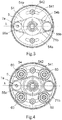
Figures 3 and 4 are sections of a front view of two variant embodiments of the speed reducer according to the invention. -
Figures 5 and 6 are sections of front and side views of a further variant embodiment of the speed reducer according to the invention. -
Figure 7 is an exploded view of the speed reducer offigures 5 and 6 . -
Figure 8 is an exploded view of a further variant embodiment of the speed reducer according to the invention. - While the invention is susceptible of various modifications and alternative forms, some non-limitative embodiments, given by way of example, are described herein below in details.
- It should be understood, however, that there is no intention to limit the invention to the specific embodiments disclosed, but, on the contrary, the intention of the invention is to cover all modifications, alternative constructions and equivalents falling within the scope of the invention as defined in the claims.
- Therefore, in the description below, the use of "for example", "etc", "or" indicates non-exclusive alternatives without limitation unless otherwise defined; the use of "also" means "among which, but not limited to", unless otherwise defined; the use of "include/comprise" means "include/comprise, but not limited to," unless otherwise defined.
-
Fig.1 is a section of a top view of an epicyclic speed reducer, denoted byreference numeral 1, to transmit a rotational motion from one input shaft - typically a driving shaft - to an output shaft that is the driven shaft. Thespeed reducer 1 allows the angular velocity of the driving shaft to be transferred, providing to the driven shaft a rotational motion with a reduced angular velocity. - In the embodiment shown in
fig.1 thespeed reducer 1 comprises acasing 4 provided with two openings (2a, 2b) arranged on two opposite faces thereof. Afirst opening 2a allows the rotational motion to be introduced inside thecasing 4 and a second opening 2b allows it to go outside it. - The driving shaft and the driven shaft (not shown in the figure) are coaxial, that is they rotate about the same axis of rotation α and are inserted in the
speed reducer 1 each one by a corresponding end (2, 3), at the first opening (2a) by theend 2 of the driving shaft and at the second opening (2b) by theend 3 of the driven shaft. - Particularly the
end 2 of the driving shaft is fitted into aseat 21, obtained in a supportingelement 5 with a substantially plate-like geometry, and placed coaxial with the axis of rotation α. Such element, called as "planet carrier", supports gears, called as "planet gears", that rotate while describing a circular orbit around gears - called as "sun gears" - and that will be described below more in details. - The rotational motion of the driving shaft entering the
casing 4 of thespeed reducer 1 is therefore transferred directly to theplanet carrier 5 thus resulting in that a rotation of the driving shaft corresponds to the same rotation of theplanet carrier 5. - At the first opening 2a and inside the
casing 4 there is provided a first gears 20 - called below as "first sun gear" - coaxial with the driving shaft and fastened to thecasing 4 through tighteningpins 300. Between thefirst sun gear 20 and the driving shaft a rolling-element bearing 6 is interposed, which is inserted so as to abut onshoulders 51a provided on theplanet carrier 5, to allow loads exerted on the driving shaft to be withstood, while further releasing the rotation thereof with respect to thefirst sun gear 20. - As mentioned above, inside the
casing 4 theplanet carrier 5 is housed that comprises two surfaces, an inner one 51 facing themotion input opening 2a and an outer one 52 on the contrary facing the motion output opening 2b. - The
planet carrier 5 develops along a direction λ orthogonal to the axis of rotation α, and it has two ends (50a,50b) placed symmetrically with respect to the latter. - At each one of the two ends there is provided a through hole, a pin (7a,7b) passing therethrough. On each one of the pins a pair of gears - or "planet" gears - is rigidly constrained, a first pair (8a,9a) for the pin (7a) and a second pair (8b,9b) for the pin (7b) respectively. The pins are parallel with each other and with the axis of rotation α and their coupling with the
planet carrier 5 is obtained by rotational joints (71a, 71b) for example bearings or bushings: this type of coupling enables the relative rotation of the planet gears (8a,8b,9a,9b) with respect to the rotation of theplanet carrier 5 exerted by the driving shaft. - In particular first planet gears (8a,8b) are fitted on the portions of the pins (7a,7b) respectively that protrude from the
inner surface 51 of theplanet carrier 5 and are kinematically connected with each other through a first toothed belt 10 (seefigure 2 ). Thebelt 10 is a continuous band and it forms a loop and preferably it is made of elastomeric material. It is further arranged with an orientation parallel to the direction λ and it further engages thefirst sun gear 20, that is placed between the two first planet gears (8a, 8b). - Such arrangement enables a compound rotational motion of the first planet gears (8a,8b), obtained as the combination of a motion given by their circular trajectory about the
first sun gear 20 and by their own relative rotational motion with respect to theplanet carrier 5 supporting them. - Since the pins (7a, 7b) rigidly restrain the rotation of the first planet gears (8a, 8b) and of respective second planet gears (9a, 9b) the kinematics composed of the
first sun gear 20, the first planet gears (8a,8b) and of the firsttoothed belt 10 allows the same relative rotation of the first planet gears (8a,8b) to be transferred to the second planet gears (9a,9b) through the pins (7a,7b). - The second planet gears (9a, 9b) are fitted on the portions of the pins (7a,7b) respectively protruding from the
outer surface 52 of theplanet carrier 5. Preferably the first (8a,8b) and second (9a,9b) planet gears have a different diameter and/or number of teeth, and such constructional parameters can vary for example depending on the gear ratio desired to be obtained by thespeed reducer 1. - Likewise the first planet gears, also the second planet gears (9a,9b) are kinematically constrained to a
second sun gear 30 by a secondtoothed belt 11, placed parallel to thefirst belt 10 and which can be seen infig.2 . - In details, the
planet carrier 5 is interposed between the first 20 and second 30 sun gear the latter being rigidly fitted on the driven shaft and coaxial with the axis of rotation α. A second rolling-element bearing 12, inserted so as to abut onfurther shoulders 51b protruding from theouter surface 52 of theplanet carrier 5, allows a relative rotation of thesecond sun gear 30 with respect to the rotation of theplanet carrier 5. - Also the second planet gears (9a, 9b) are therefore characterized by a compound rotational motion: they rotate at the same angular velocity of the first planet gears (8a,8b) and contemporaneously they describe a circular trajectory around the
second sun gear 30 which is rotated through the secondtoothed belt 11. - The
second sun gear 30 is rigidly constrained to theend 3 of the driven shaft, and theretofore it receives a rotational motion that is the output rotation motion from thespeed reducer 1. - From the description above it is clear how the speed reducer described allows the above objects to be achieved.
- Therefore it is clear for a person skilled in the art that it is possible to make changes and variants to the solution described with reference to the above figures without for this reason departing from the scope of protection of the present patent as defined by the annexed claims.
- For example in order to regulate the tension of the first 10 and
second belt 11 of thespeed reducer 1, in one alternative embodiment of the invention, shown infig.3 , it is possible to provide adiscoid element 54, with an eccentric cam profile, to be fastened on one of theinner surface 51 orouter surface 52 of theplanet carrier 5 and coaxial with the rotation thereof. - The ends (50a, 50b) of the planet carrier, instead of being perforated, in this case provide recesses (55a,55b) that allow a radial mobility of the pins (7a, 7b) on which the first (8a,9a) and second (8b,9b) pair of planet gears are fitted respectively, by means of a suitable rotation of the
discoid element 54. - The
discoid element 54 comprises two areas (54a,54b) with different radial extensions: afirst area 54a, that is external and with a greater radius, and asecond area 54b that is internal and with a smaller radial profile provided with eccentricity. - In particular the
first area 54a comprisesslots 541 that receive a screw-tighteningnut pair 542 to retain thediscoid element 54 to theplanet carrier 5 and allow it to rotate about the axis of rotation α. The profile of thesecond area 54b is maintained in forced contact with the flanks of the pins (7a, 7b) therefore allowing, after rotating thediscoid element 54, the translation of the pins, and therefore of the pairs of planet gears meshing the belts, to be regulated along the direction λ. - In a further constructional variant of the
speed reducer 1 the tension of the belts is obtained by means of tensioning frictional wheels. Such variant is shown infig.4 and it provides, in addition to the variant offig.3 described above, the provision of twodiscoid elements 54, one being fastened to theinner surface 51 and one being fastened to theouter surface 52 of the planet carrier 5 (fig.4 shows only the one fastened to the outer surface). - On the
slots 541 of each of the twodiscoid elements 54 fouridle wheels 60, with smooth profile, are fastened, whose position can be regulated on the length of the slots, and each one pressing the branches of the belts (10, 11) not meshing with the first (8a,8b) and second (9a,9b) planet gears respectively. - In such arrangement the pins (7a, 7b) of the planet gears are maintained stationary with respect to the
planet carrier 5. - A further embodiment, shown in
figs. 5, 6 and7 provides to use a first group of four planet gears (8a,8b,8c,8d) for thefirst sun gear 20, and a second group of additional four planet gears (9a,9b,9c,9d) for thesecond sun gear 30. For each one of the two groups, the four planet gears are arranged in an axial-symmetric manner on the respective inner faces 51 - such as shown infig.5 - and outer face 52 - such as shown infig. 6 - of theplanet carrier 5. In such variant, each one of the two belts (10, 11) can have teeth only on one face or on both the faces, and can mesh the respective sun gear and some or all the respective planet gears, following different paths depending for example on the values of the torque desired as output from thespeed reducer 1. - The variant embodiment shown in
fig.6 on the contrary provides the use of flat belts (13, 14) with a V-shape or trapezoidal shape, instead of the toothed belts. Accordingly all the gears used in such variant have a profile with no teeth. Likewise what described infig.3 and fig.4 such arrangement providesdiscoid elements 54 applied to theplanet carrier 5 to selectively regulate the tension of the fist (8a, 8b) and second (9a,9b) planet gears, through a radial translation of the pins (7a, 7b) in the recesses (55a,55b) or, as an alternative, through the use ofidle gears 60 that press the branches of the belts not meshing the planet gears and sun gear.
Claims (8)
- Epicyclic speed reducer (1), comprising a casing (4) comprising a first (2a) and a second opening (2b) arranged on opposite faces of said casing (4), and wherein the casing (4) houses inside it:- a first sun gear (20) fastened inside the casing (4) at said first opening (2a),- a second sun gear (30) coaxial with the first sun gear (20) and having an axis passing from said first opening (2a) to said second opening (2b),- a first planet gear (8a, 8b) adapted to describe a circular orbit around said first sun gear (20),- a second planet gear (9a, 9b) adapted to describe a circular orbit around said second sun gear (30),- a supporting element (5) interposed between said first (20) and second (30) sun gear and adapted to rotate around said axis, said supporting element (5) connected to said first and second planet gear in such a way as to allow a relative rotation of the supporting element (5) with respect to said first and second planet gear,- a first belt (10) connected to the first planet gear (8a, 8b) and to the first sun gear (20),- a second belt (11) connected to the second planet gear (9a, 9b) and to the second sun gear (30),characterized in that the supporting element (5) is provided with a seat (21) coaxial with said axis and adapted to be fitted on one end (2) of a driving shaft such that when the seat is fitted on the driving shaft the supporting element (5) and the driving shaft are rigidly connected.
- Epicyclic speed reducer (1) according to claim 1, wherein the supporting element (5) has two ends (50a, 50b) arranged symmetrically to said axis and provided with at least one recess (55a, 55b) in which a pin (7a, 7b) is inserted, said pin being constrained to the supporting element (5) through a rotational joint (71a, 71b).
- Epicyclic speed reducer (1) according to claim 2, wherein the pin (7a, 7b) passes through the supporting element and wherein the first and the second planet gear are rigidly constrained to two opposite ends of the pin (7a, 7b).
- Epicyclic speed reducer (1) according to any one of the preceding claims, further comprising a discoid element (54) provided with a slot (541), wherein the discoid element (54) is applied to one surface of the supporting element (5) orthogonal to said axis by means of a screw-bolt coupling (542), wherein said screw-bolt coupling (542) is formed by a screw that passes through said slot and said supporting element, and a bolt engaged with the screw, in such a way that such screw-bolt coupling allows a relative rotation of the discoid element (54) relative to the supporting element (5) for a distance corresponding to the length of the slot.
- Epicyclic speed reducer (1) according to claim 4, wherein the discoid element (54) comprises an internal area (54b) provided with an eccentric profile, wherein said eccentric profile is maintained in forced contact with a flank of the pin (7a, 7b) in such that the rotation of the discoid element (54) corresponds to a radial translation of the pin (7a, 7b) on the supporting element (5).
- Epicyclic speed reducer (1) according to claim 4, wherein on the slot (541) an idle gear (60) is fastened adapted to press a branch of one of the first and second belt (10,11) interposed between a first gripping point of said belt with the respective planet gear and a second gripping point of the belt with the respective sun gear.
- Epicyclic speed reducer (1) according to any one of the preceding claims, wherein the supporting element (5) supports two groups of four planet gears (8a, 8b, 8c, 8d, 9a, 9b, 9c, 9d), wherein the first belt (10) meshes the first sun gear (20) and at least one planet gear of a first group (8a, 8b, 8c, 8d) of said two groups, and wherein the second belt (11) meshes the second sun gear (30) and at least one planet gear of a second group (9a, 9b, 9c, 9d) of said two groups, wherein the belts (10, 11) have a toothed profile on both faces and each one meshes one or more planet gears of a respective group.
- Epicyclic speed reducer (1) according to any one of the preceding claims, wherein the two belts (10, 11) have a flat or "V" or trapezoidal profile.
Applications Claiming Priority (2)
| Application Number | Priority Date | Filing Date | Title |
|---|---|---|---|
| ITUB2015A002131A ITUB20152131A1 (en) | 2015-07-13 | 2015-07-13 | ROTATIONAL SPEED REDUCER |
| PCT/IB2016/054114 WO2017009759A1 (en) | 2015-07-13 | 2016-07-08 | Rotational speed reducer |
Publications (2)
| Publication Number | Publication Date |
|---|---|
| EP3322917A1 EP3322917A1 (en) | 2018-05-23 |
| EP3322917B1 true EP3322917B1 (en) | 2019-04-24 |
Family
ID=54347673
Family Applications (1)
| Application Number | Title | Priority Date | Filing Date |
|---|---|---|---|
| EP16745843.9A Not-in-force EP3322917B1 (en) | 2015-07-13 | 2016-07-08 | Rotational speed reducer |
Country Status (4)
| Country | Link |
|---|---|
| US (1) | US10539206B2 (en) |
| EP (1) | EP3322917B1 (en) |
| IT (1) | ITUB20152131A1 (en) |
| WO (1) | WO2017009759A1 (en) |
Families Citing this family (2)
| Publication number | Priority date | Publication date | Assignee | Title |
|---|---|---|---|---|
| EP4488547B1 (en) * | 2019-07-17 | 2026-03-25 | Milwaukee Electric Tool Corporation | Axial pump assemblies |
| CN114274078A (en) * | 2021-12-31 | 2022-04-05 | 达闼机器人有限公司 | Alignment jig and using method thereof |
Family Cites Families (12)
| Publication number | Priority date | Publication date | Assignee | Title |
|---|---|---|---|---|
| US2956451A (en) | 1959-02-17 | 1960-10-18 | Bowman Spencer | Planetary gear-type speed reducer |
| US3979971A (en) * | 1975-03-03 | 1976-09-14 | Hills-Mccanna Company | Differential drive |
| CA1098341A (en) | 1979-02-19 | 1981-03-31 | Frank L. Stromotich | Epicyclic cog belt speed reducer |
| CA1154982A (en) * | 1980-02-15 | 1983-10-11 | Frank L. Stromotich | Compound epicyclic cog belt speed reducer |
| US4919011A (en) | 1989-01-03 | 1990-04-24 | Mark T. Basseches | Roller speed reduction drive |
| US5269734A (en) * | 1990-10-19 | 1993-12-14 | Menge Sr Theodore L | Gear reducing device |
| IT1250861B (en) * | 1991-11-12 | 1995-04-21 | Fiat Avio Spa | EPICYCLOIDAL SPEED REDUCER SUITABLE TO BE INSERTED IN THE TRANSMISSION BETWEEN A GAS TURBINE AND THE AIR COMPRESSOR OF AN AIRCRAFT ENGINE. |
| DE10124265B4 (en) * | 2001-05-18 | 2015-10-29 | Gustav Klauke Gmbh | pump |
| JP4004256B2 (en) | 2001-09-13 | 2007-11-07 | ナブテスコ株式会社 | Eccentric rocking speed reducer |
| DE10160685C2 (en) * | 2001-12-11 | 2003-10-02 | Sew Eurodrive Gmbh & Co | Planetary gear, geared motor and series of geared motors |
| BR112014007449B1 (en) * | 2011-09-29 | 2020-11-24 | National Oilwell Varco Norway As | TIGHTENING SYSTEM FOR MAKING AND BREAKING THREADED CONNECTIONS |
| DE102011083802A1 (en) * | 2011-09-30 | 2013-04-04 | Schaeffler Technologies AG & Co. KG | Aggregate with a pulley drive |
-
2015
- 2015-07-13 IT ITUB2015A002131A patent/ITUB20152131A1/en unknown
-
2016
- 2016-07-08 WO PCT/IB2016/054114 patent/WO2017009759A1/en not_active Ceased
- 2016-07-08 US US15/740,266 patent/US10539206B2/en not_active Expired - Fee Related
- 2016-07-08 EP EP16745843.9A patent/EP3322917B1/en not_active Not-in-force
Non-Patent Citations (1)
| Title |
|---|
| None * |
Also Published As
| Publication number | Publication date |
|---|---|
| US20180187754A1 (en) | 2018-07-05 |
| ITUB20152131A1 (en) | 2017-01-13 |
| EP3322917A1 (en) | 2018-05-23 |
| US10539206B2 (en) | 2020-01-21 |
| WO2017009759A1 (en) | 2017-01-19 |
Similar Documents
| Publication | Publication Date | Title |
|---|---|---|
| US4023440A (en) | Motion transmitting devices | |
| US4228698A (en) | Speed reducer | |
| US4391163A (en) | Planetary gear assembly | |
| US5080638A (en) | Cycloidal gearing | |
| CA2677552C (en) | Continuously variable transmission | |
| US5632702A (en) | Continuously variable transmission | |
| US10539206B2 (en) | Rotational speed reducer | |
| KR101241819B1 (en) | Continuously variable transmission | |
| US12007023B2 (en) | Belt for continuously variable transmission | |
| RU2719091C1 (en) | Roller-screw reduction gear (embodiments), drive mechanism and hinged assembly comprising such reduction gear | |
| JP2016145620A (en) | Power transmission device | |
| KR101254596B1 (en) | continuously variable transmission of hub type | |
| JP7033671B2 (en) | Variable transmission with nested pulleys | |
| US7344467B2 (en) | Self-regulating continuously variable transmission | |
| KR101027833B1 (en) | Continuously variable transmission | |
| CN118254154B (en) | Transmission equipment and robot power unit | |
| RU2211971C1 (en) | Power-driven variable-speed transmission | |
| JP4331483B2 (en) | Motor built-in roller | |
| JP2523069Y2 (en) | Inner mesh planetary gear structure | |
| KR101327332B1 (en) | continuously variable transmission of hub type | |
| CA1154982A (en) | Compound epicyclic cog belt speed reducer | |
| KR200409497Y1 (en) | Hollow Planetary Gear Reducer | |
| RU2674915C1 (en) | Planetary gear | |
| TWM573804U (en) | An encentric speed-reduced device | |
| KR20230061129A (en) | Cycloid reducer |
Legal Events
| Date | Code | Title | Description |
|---|---|---|---|
| STAA | Information on the status of an ep patent application or granted ep patent |
Free format text: STATUS: THE INTERNATIONAL PUBLICATION HAS BEEN MADE |
|
| PUAI | Public reference made under article 153(3) epc to a published international application that has entered the european phase |
Free format text: ORIGINAL CODE: 0009012 |
|
| STAA | Information on the status of an ep patent application or granted ep patent |
Free format text: STATUS: REQUEST FOR EXAMINATION WAS MADE |
|
| 17P | Request for examination filed |
Effective date: 20171122 |
|
| AK | Designated contracting states |
Kind code of ref document: A1 Designated state(s): AL AT BE BG CH CY CZ DE DK EE ES FI FR GB GR HR HU IE IS IT LI LT LU LV MC MK MT NL NO PL PT RO RS SE SI SK SM TR |
|
| AX | Request for extension of the european patent |
Extension state: BA ME |
|
| DAV | Request for validation of the european patent (deleted) | ||
| DAX | Request for extension of the european patent (deleted) | ||
| GRAP | Despatch of communication of intention to grant a patent |
Free format text: ORIGINAL CODE: EPIDOSNIGR1 |
|
| STAA | Information on the status of an ep patent application or granted ep patent |
Free format text: STATUS: GRANT OF PATENT IS INTENDED |
|
| INTG | Intention to grant announced |
Effective date: 20181126 |
|
| GRAS | Grant fee paid |
Free format text: ORIGINAL CODE: EPIDOSNIGR3 |
|
| GRAA | (expected) grant |
Free format text: ORIGINAL CODE: 0009210 |
|
| STAA | Information on the status of an ep patent application or granted ep patent |
Free format text: STATUS: THE PATENT HAS BEEN GRANTED |
|
| AK | Designated contracting states |
Kind code of ref document: B1 Designated state(s): AL AT BE BG CH CY CZ DE DK EE ES FI FR GB GR HR HU IE IS IT LI LT LU LV MC MK MT NL NO PL PT RO RS SE SI SK SM TR |
|
| REG | Reference to a national code |
Ref country code: GB Ref legal event code: FG4D |
|
| REG | Reference to a national code |
Ref country code: CH Ref legal event code: EP |
|
| REG | Reference to a national code |
Ref country code: AT Ref legal event code: REF Ref document number: 1124516 Country of ref document: AT Kind code of ref document: T Effective date: 20190515 Ref country code: IE Ref legal event code: FG4D |
|
| REG | Reference to a national code |
Ref country code: DE Ref legal event code: R096 Ref document number: 602016012927 Country of ref document: DE |
|
| REG | Reference to a national code |
Ref country code: NL Ref legal event code: MP Effective date: 20190424 |
|
| REG | Reference to a national code |
Ref country code: LT Ref legal event code: MG4D |
|
| PG25 | Lapsed in a contracting state [announced via postgrant information from national office to epo] |
Ref country code: NL Free format text: LAPSE BECAUSE OF FAILURE TO SUBMIT A TRANSLATION OF THE DESCRIPTION OR TO PAY THE FEE WITHIN THE PRESCRIBED TIME-LIMIT Effective date: 20190424 |
|
| PG25 | Lapsed in a contracting state [announced via postgrant information from national office to epo] |
Ref country code: AL Free format text: LAPSE BECAUSE OF FAILURE TO SUBMIT A TRANSLATION OF THE DESCRIPTION OR TO PAY THE FEE WITHIN THE PRESCRIBED TIME-LIMIT Effective date: 20190424 Ref country code: PT Free format text: LAPSE BECAUSE OF FAILURE TO SUBMIT A TRANSLATION OF THE DESCRIPTION OR TO PAY THE FEE WITHIN THE PRESCRIBED TIME-LIMIT Effective date: 20190824 Ref country code: NO Free format text: LAPSE BECAUSE OF FAILURE TO SUBMIT A TRANSLATION OF THE DESCRIPTION OR TO PAY THE FEE WITHIN THE PRESCRIBED TIME-LIMIT Effective date: 20190724 Ref country code: ES Free format text: LAPSE BECAUSE OF FAILURE TO SUBMIT A TRANSLATION OF THE DESCRIPTION OR TO PAY THE FEE WITHIN THE PRESCRIBED TIME-LIMIT Effective date: 20190424 Ref country code: LT Free format text: LAPSE BECAUSE OF FAILURE TO SUBMIT A TRANSLATION OF THE DESCRIPTION OR TO PAY THE FEE WITHIN THE PRESCRIBED TIME-LIMIT Effective date: 20190424 Ref country code: HR Free format text: LAPSE BECAUSE OF FAILURE TO SUBMIT A TRANSLATION OF THE DESCRIPTION OR TO PAY THE FEE WITHIN THE PRESCRIBED TIME-LIMIT Effective date: 20190424 Ref country code: SE Free format text: LAPSE BECAUSE OF FAILURE TO SUBMIT A TRANSLATION OF THE DESCRIPTION OR TO PAY THE FEE WITHIN THE PRESCRIBED TIME-LIMIT Effective date: 20190424 Ref country code: FI Free format text: LAPSE BECAUSE OF FAILURE TO SUBMIT A TRANSLATION OF THE DESCRIPTION OR TO PAY THE FEE WITHIN THE PRESCRIBED TIME-LIMIT Effective date: 20190424 |
|
| PG25 | Lapsed in a contracting state [announced via postgrant information from national office to epo] |
Ref country code: PL Free format text: LAPSE BECAUSE OF FAILURE TO SUBMIT A TRANSLATION OF THE DESCRIPTION OR TO PAY THE FEE WITHIN THE PRESCRIBED TIME-LIMIT Effective date: 20190424 Ref country code: RS Free format text: LAPSE BECAUSE OF FAILURE TO SUBMIT A TRANSLATION OF THE DESCRIPTION OR TO PAY THE FEE WITHIN THE PRESCRIBED TIME-LIMIT Effective date: 20190424 Ref country code: LV Free format text: LAPSE BECAUSE OF FAILURE TO SUBMIT A TRANSLATION OF THE DESCRIPTION OR TO PAY THE FEE WITHIN THE PRESCRIBED TIME-LIMIT Effective date: 20190424 Ref country code: BG Free format text: LAPSE BECAUSE OF FAILURE TO SUBMIT A TRANSLATION OF THE DESCRIPTION OR TO PAY THE FEE WITHIN THE PRESCRIBED TIME-LIMIT Effective date: 20190724 Ref country code: GR Free format text: LAPSE BECAUSE OF FAILURE TO SUBMIT A TRANSLATION OF THE DESCRIPTION OR TO PAY THE FEE WITHIN THE PRESCRIBED TIME-LIMIT Effective date: 20190725 |
|
| REG | Reference to a national code |
Ref country code: AT Ref legal event code: MK05 Ref document number: 1124516 Country of ref document: AT Kind code of ref document: T Effective date: 20190424 |
|
| PG25 | Lapsed in a contracting state [announced via postgrant information from national office to epo] |
Ref country code: IS Free format text: LAPSE BECAUSE OF FAILURE TO SUBMIT A TRANSLATION OF THE DESCRIPTION OR TO PAY THE FEE WITHIN THE PRESCRIBED TIME-LIMIT Effective date: 20190824 |
|
| REG | Reference to a national code |
Ref country code: DE Ref legal event code: R097 Ref document number: 602016012927 Country of ref document: DE |
|
| PG25 | Lapsed in a contracting state [announced via postgrant information from national office to epo] |
Ref country code: CZ Free format text: LAPSE BECAUSE OF FAILURE TO SUBMIT A TRANSLATION OF THE DESCRIPTION OR TO PAY THE FEE WITHIN THE PRESCRIBED TIME-LIMIT Effective date: 20190424 Ref country code: SK Free format text: LAPSE BECAUSE OF FAILURE TO SUBMIT A TRANSLATION OF THE DESCRIPTION OR TO PAY THE FEE WITHIN THE PRESCRIBED TIME-LIMIT Effective date: 20190424 Ref country code: EE Free format text: LAPSE BECAUSE OF FAILURE TO SUBMIT A TRANSLATION OF THE DESCRIPTION OR TO PAY THE FEE WITHIN THE PRESCRIBED TIME-LIMIT Effective date: 20190424 Ref country code: DK Free format text: LAPSE BECAUSE OF FAILURE TO SUBMIT A TRANSLATION OF THE DESCRIPTION OR TO PAY THE FEE WITHIN THE PRESCRIBED TIME-LIMIT Effective date: 20190424 Ref country code: RO Free format text: LAPSE BECAUSE OF FAILURE TO SUBMIT A TRANSLATION OF THE DESCRIPTION OR TO PAY THE FEE WITHIN THE PRESCRIBED TIME-LIMIT Effective date: 20190424 Ref country code: AT Free format text: LAPSE BECAUSE OF FAILURE TO SUBMIT A TRANSLATION OF THE DESCRIPTION OR TO PAY THE FEE WITHIN THE PRESCRIBED TIME-LIMIT Effective date: 20190424 |
|
| PG25 | Lapsed in a contracting state [announced via postgrant information from national office to epo] |
Ref country code: MC Free format text: LAPSE BECAUSE OF FAILURE TO SUBMIT A TRANSLATION OF THE DESCRIPTION OR TO PAY THE FEE WITHIN THE PRESCRIBED TIME-LIMIT Effective date: 20190424 Ref country code: SM Free format text: LAPSE BECAUSE OF FAILURE TO SUBMIT A TRANSLATION OF THE DESCRIPTION OR TO PAY THE FEE WITHIN THE PRESCRIBED TIME-LIMIT Effective date: 20190424 |
|
| PLBE | No opposition filed within time limit |
Free format text: ORIGINAL CODE: 0009261 |
|
| REG | Reference to a national code |
Ref country code: CH Ref legal event code: PL |
|
| STAA | Information on the status of an ep patent application or granted ep patent |
Free format text: STATUS: NO OPPOSITION FILED WITHIN TIME LIMIT |
|
| PG25 | Lapsed in a contracting state [announced via postgrant information from national office to epo] |
Ref country code: TR Free format text: LAPSE BECAUSE OF FAILURE TO SUBMIT A TRANSLATION OF THE DESCRIPTION OR TO PAY THE FEE WITHIN THE PRESCRIBED TIME-LIMIT Effective date: 20190424 |
|
| 26N | No opposition filed |
Effective date: 20200127 |
|
| REG | Reference to a national code |
Ref country code: BE Ref legal event code: MM Effective date: 20190731 |
|
| PG25 | Lapsed in a contracting state [announced via postgrant information from national office to epo] |
Ref country code: SI Free format text: LAPSE BECAUSE OF FAILURE TO SUBMIT A TRANSLATION OF THE DESCRIPTION OR TO PAY THE FEE WITHIN THE PRESCRIBED TIME-LIMIT Effective date: 20190424 Ref country code: LU Free format text: LAPSE BECAUSE OF NON-PAYMENT OF DUE FEES Effective date: 20190708 Ref country code: CH Free format text: LAPSE BECAUSE OF NON-PAYMENT OF DUE FEES Effective date: 20190731 Ref country code: LI Free format text: LAPSE BECAUSE OF NON-PAYMENT OF DUE FEES Effective date: 20190731 Ref country code: BE Free format text: LAPSE BECAUSE OF NON-PAYMENT OF DUE FEES Effective date: 20190731 |
|
| PG25 | Lapsed in a contracting state [announced via postgrant information from national office to epo] |
Ref country code: IE Free format text: LAPSE BECAUSE OF NON-PAYMENT OF DUE FEES Effective date: 20190708 |
|
| PG25 | Lapsed in a contracting state [announced via postgrant information from national office to epo] |
Ref country code: CY Free format text: LAPSE BECAUSE OF FAILURE TO SUBMIT A TRANSLATION OF THE DESCRIPTION OR TO PAY THE FEE WITHIN THE PRESCRIBED TIME-LIMIT Effective date: 20190424 |
|
| PG25 | Lapsed in a contracting state [announced via postgrant information from national office to epo] |
Ref country code: MT Free format text: LAPSE BECAUSE OF FAILURE TO SUBMIT A TRANSLATION OF THE DESCRIPTION OR TO PAY THE FEE WITHIN THE PRESCRIBED TIME-LIMIT Effective date: 20190424 Ref country code: HU Free format text: LAPSE BECAUSE OF FAILURE TO SUBMIT A TRANSLATION OF THE DESCRIPTION OR TO PAY THE FEE WITHIN THE PRESCRIBED TIME-LIMIT; INVALID AB INITIO Effective date: 20160708 |
|
| PG25 | Lapsed in a contracting state [announced via postgrant information from national office to epo] |
Ref country code: MK Free format text: LAPSE BECAUSE OF FAILURE TO SUBMIT A TRANSLATION OF THE DESCRIPTION OR TO PAY THE FEE WITHIN THE PRESCRIBED TIME-LIMIT Effective date: 20190424 |
|
| PGFP | Annual fee paid to national office [announced via postgrant information from national office to epo] |
Ref country code: IT Payment date: 20220729 Year of fee payment: 7 Ref country code: GB Payment date: 20220716 Year of fee payment: 7 Ref country code: DE Payment date: 20220728 Year of fee payment: 7 |
|
| PGFP | Annual fee paid to national office [announced via postgrant information from national office to epo] |
Ref country code: FR Payment date: 20220726 Year of fee payment: 7 |
|
| REG | Reference to a national code |
Ref country code: DE Ref legal event code: R119 Ref document number: 602016012927 Country of ref document: DE |
|
| GBPC | Gb: european patent ceased through non-payment of renewal fee |
Effective date: 20230708 |
|
| PG25 | Lapsed in a contracting state [announced via postgrant information from national office to epo] |
Ref country code: DE Free format text: LAPSE BECAUSE OF NON-PAYMENT OF DUE FEES Effective date: 20240201 Ref country code: GB Free format text: LAPSE BECAUSE OF NON-PAYMENT OF DUE FEES Effective date: 20230708 |
|
| PG25 | Lapsed in a contracting state [announced via postgrant information from national office to epo] |
Ref country code: FR Free format text: LAPSE BECAUSE OF NON-PAYMENT OF DUE FEES Effective date: 20230731 |
|
| PG25 | Lapsed in a contracting state [announced via postgrant information from national office to epo] |
Ref country code: IT Free format text: LAPSE BECAUSE OF NON-PAYMENT OF DUE FEES Effective date: 20230708 |