EP3322864B1 - Hollow-floor elements and method for manufacturing a hollow-floor element - Google Patents
Hollow-floor elements and method for manufacturing a hollow-floor element Download PDFInfo
- Publication number
- EP3322864B1 EP3322864B1 EP16732936.6A EP16732936A EP3322864B1 EP 3322864 B1 EP3322864 B1 EP 3322864B1 EP 16732936 A EP16732936 A EP 16732936A EP 3322864 B1 EP3322864 B1 EP 3322864B1
- Authority
- EP
- European Patent Office
- Prior art keywords
- hollow
- semi
- hydrate
- floor
- load
- Prior art date
- Legal status (The legal status is an assumption and is not a legal conclusion. Google has not performed a legal analysis and makes no representation as to the accuracy of the status listed.)
- Active
Links
- 238000004519 manufacturing process Methods 0.000 title claims description 19
- 238000000034 method Methods 0.000 title claims description 18
- 229910052602 gypsum Inorganic materials 0.000 claims description 37
- 239000010440 gypsum Substances 0.000 claims description 37
- OSGAYBCDTDRGGQ-UHFFFAOYSA-L calcium sulfate Chemical compound [Ca+2].[O-]S([O-])(=O)=O OSGAYBCDTDRGGQ-UHFFFAOYSA-L 0.000 claims description 26
- 239000003365 glass fiber Substances 0.000 claims description 15
- 238000001035 drying Methods 0.000 claims description 14
- 235000011132 calcium sulphate Nutrition 0.000 claims description 13
- 239000001175 calcium sulphate Substances 0.000 claims description 13
- XLYOFNOQVPJJNP-UHFFFAOYSA-N water Substances O XLYOFNOQVPJJNP-UHFFFAOYSA-N 0.000 claims description 12
- 239000000470 constituent Substances 0.000 claims description 10
- 239000000203 mixture Substances 0.000 claims description 10
- 229920003043 Cellulose fiber Polymers 0.000 claims description 9
- 239000011159 matrix material Substances 0.000 claims description 9
- 238000004026 adhesive bonding Methods 0.000 claims description 4
- 238000005304 joining Methods 0.000 claims description 3
- 238000009408 flooring Methods 0.000 description 7
- 239000000835 fiber Substances 0.000 description 6
- 239000000463 material Substances 0.000 description 5
- 239000000654 additive Substances 0.000 description 3
- 238000000576 coating method Methods 0.000 description 3
- 230000018044 dehydration Effects 0.000 description 3
- 238000006297 dehydration reaction Methods 0.000 description 3
- 150000004683 dihydrates Chemical class 0.000 description 3
- 239000013078 crystal Substances 0.000 description 2
- 238000002791 soaking Methods 0.000 description 2
- 241000196324 Embryophyta Species 0.000 description 1
- 244000068988 Glycine max Species 0.000 description 1
- 238000005299 abrasion Methods 0.000 description 1
- 238000005452 bending Methods 0.000 description 1
- 230000006835 compression Effects 0.000 description 1
- 238000007906 compression Methods 0.000 description 1
- 239000011094 fiberboard Substances 0.000 description 1
- 239000008240 homogeneous mixture Substances 0.000 description 1
- 239000007788 liquid Substances 0.000 description 1
- 238000012423 maintenance Methods 0.000 description 1
- 238000002156 mixing Methods 0.000 description 1
- 230000003287 optical effect Effects 0.000 description 1
- 238000002360 preparation method Methods 0.000 description 1
- 239000012779 reinforcing material Substances 0.000 description 1
- 230000000284 resting effect Effects 0.000 description 1
- 238000000518 rheometry Methods 0.000 description 1
- 239000000126 substance Substances 0.000 description 1
Images
Classifications
-
- E—FIXED CONSTRUCTIONS
- E04—BUILDING
- E04F—FINISHING WORK ON BUILDINGS, e.g. STAIRS, FLOORS
- E04F15/00—Flooring
- E04F15/02—Flooring or floor layers composed of a number of similar elements
- E04F15/024—Sectional false floors, e.g. computer floors
- E04F15/02405—Floor panels
-
- E—FIXED CONSTRUCTIONS
- E04—BUILDING
- E04F—FINISHING WORK ON BUILDINGS, e.g. STAIRS, FLOORS
- E04F15/00—Flooring
- E04F15/02—Flooring or floor layers composed of a number of similar elements
- E04F15/10—Flooring or floor layers composed of a number of similar elements of other materials, e.g. fibrous or chipped materials, organic plastics, magnesite tiles, hardboard, or with a top layer of other materials
- E04F15/107—Flooring or floor layers composed of a number of similar elements of other materials, e.g. fibrous or chipped materials, organic plastics, magnesite tiles, hardboard, or with a top layer of other materials composed of several layers, e.g. sandwich panels
-
- B—PERFORMING OPERATIONS; TRANSPORTING
- B32—LAYERED PRODUCTS
- B32B—LAYERED PRODUCTS, i.e. PRODUCTS BUILT-UP OF STRATA OF FLAT OR NON-FLAT, e.g. CELLULAR OR HONEYCOMB, FORM
- B32B13/00—Layered products comprising a a layer of water-setting substance, e.g. concrete, plaster, asbestos cement, or like builders' material
- B32B13/02—Layered products comprising a a layer of water-setting substance, e.g. concrete, plaster, asbestos cement, or like builders' material with fibres or particles being present as additives in the layer
-
- B—PERFORMING OPERATIONS; TRANSPORTING
- B32—LAYERED PRODUCTS
- B32B—LAYERED PRODUCTS, i.e. PRODUCTS BUILT-UP OF STRATA OF FLAT OR NON-FLAT, e.g. CELLULAR OR HONEYCOMB, FORM
- B32B13/00—Layered products comprising a a layer of water-setting substance, e.g. concrete, plaster, asbestos cement, or like builders' material
- B32B13/04—Layered products comprising a a layer of water-setting substance, e.g. concrete, plaster, asbestos cement, or like builders' material comprising such water setting substance as the main or only constituent of a layer, which is next to another layer of the same or of a different material
-
- B—PERFORMING OPERATIONS; TRANSPORTING
- B32—LAYERED PRODUCTS
- B32B—LAYERED PRODUCTS, i.e. PRODUCTS BUILT-UP OF STRATA OF FLAT OR NON-FLAT, e.g. CELLULAR OR HONEYCOMB, FORM
- B32B3/00—Layered products comprising a layer with external or internal discontinuities or unevennesses, or a layer of non-planar form; Layered products having particular features of form
- B32B3/02—Layered products comprising a layer with external or internal discontinuities or unevennesses, or a layer of non-planar form; Layered products having particular features of form characterised by features of form at particular places, e.g. in edge regions
- B32B3/06—Layered products comprising a layer with external or internal discontinuities or unevennesses, or a layer of non-planar form; Layered products having particular features of form characterised by features of form at particular places, e.g. in edge regions for securing layers together; for attaching the product to another member, e.g. to a support, or to another product, e.g. groove/tongue, interlocking
-
- B—PERFORMING OPERATIONS; TRANSPORTING
- B32—LAYERED PRODUCTS
- B32B—LAYERED PRODUCTS, i.e. PRODUCTS BUILT-UP OF STRATA OF FLAT OR NON-FLAT, e.g. CELLULAR OR HONEYCOMB, FORM
- B32B7/00—Layered products characterised by the relation between layers; Layered products characterised by the relative orientation of features between layers, or by the relative values of a measurable parameter between layers, i.e. products comprising layers having different physical, chemical or physicochemical properties; Layered products characterised by the interconnection of layers
- B32B7/04—Interconnection of layers
- B32B7/12—Interconnection of layers using interposed adhesives or interposed materials with bonding properties
-
- E—FIXED CONSTRUCTIONS
- E04—BUILDING
- E04F—FINISHING WORK ON BUILDINGS, e.g. STAIRS, FLOORS
- E04F15/00—Flooring
- E04F15/02—Flooring or floor layers composed of a number of similar elements
- E04F15/08—Flooring or floor layers composed of a number of similar elements only of stone or stone-like material, e.g. ceramics, concrete; of glass or with a top layer of stone or stone-like material, e.g. ceramics, concrete or glass
-
- B—PERFORMING OPERATIONS; TRANSPORTING
- B32—LAYERED PRODUCTS
- B32B—LAYERED PRODUCTS, i.e. PRODUCTS BUILT-UP OF STRATA OF FLAT OR NON-FLAT, e.g. CELLULAR OR HONEYCOMB, FORM
- B32B2250/00—Layers arrangement
- B32B2250/02—2 layers
-
- B—PERFORMING OPERATIONS; TRANSPORTING
- B32—LAYERED PRODUCTS
- B32B—LAYERED PRODUCTS, i.e. PRODUCTS BUILT-UP OF STRATA OF FLAT OR NON-FLAT, e.g. CELLULAR OR HONEYCOMB, FORM
- B32B2262/00—Composition or structural features of fibres which form a fibrous or filamentary layer or are present as additives
- B32B2262/04—Cellulosic plastic fibres, e.g. rayon
-
- B—PERFORMING OPERATIONS; TRANSPORTING
- B32—LAYERED PRODUCTS
- B32B—LAYERED PRODUCTS, i.e. PRODUCTS BUILT-UP OF STRATA OF FLAT OR NON-FLAT, e.g. CELLULAR OR HONEYCOMB, FORM
- B32B2262/00—Composition or structural features of fibres which form a fibrous or filamentary layer or are present as additives
- B32B2262/10—Inorganic fibres
- B32B2262/101—Glass fibres
-
- B—PERFORMING OPERATIONS; TRANSPORTING
- B32—LAYERED PRODUCTS
- B32B—LAYERED PRODUCTS, i.e. PRODUCTS BUILT-UP OF STRATA OF FLAT OR NON-FLAT, e.g. CELLULAR OR HONEYCOMB, FORM
- B32B2419/00—Buildings or parts thereof
-
- E—FIXED CONSTRUCTIONS
- E04—BUILDING
- E04F—FINISHING WORK ON BUILDINGS, e.g. STAIRS, FLOORS
- E04F15/00—Flooring
- E04F15/02—Flooring or floor layers composed of a number of similar elements
- E04F15/02038—Flooring or floor layers composed of a number of similar elements characterised by tongue and groove connections between neighbouring flooring elements
-
- E—FIXED CONSTRUCTIONS
- E04—BUILDING
- E04F—FINISHING WORK ON BUILDINGS, e.g. STAIRS, FLOORS
- E04F2203/00—Specially structured or shaped covering, lining or flooring elements not otherwise provided for
- E04F2203/06—Specially structured or shaped covering, lining or flooring elements not otherwise provided for comprising two layers fixedly secured to one another, in offset relationship in order to form a rebate
- E04F2203/065—Specially structured or shaped covering, lining or flooring elements not otherwise provided for comprising two layers fixedly secured to one another, in offset relationship in order to form a rebate in offset relationship longitudinally as well as transversely
Definitions
- the invention relates to a method for manufacturing hollow-floor elements and to such elements.
- the invention relates to hollow-floor panels manufactured from gypsum fibreboards.
- Hollow-floor panels (cavity flooring) are known in the art.
- DE 40 21 963 A1 describes a hollow floor comprising individual support plates.
- US 5,632,848 describes a continuous manufacturing line for the preparation of gypsum fiberboards by means of a wet process. If a cavity is provided below the walk-on floor level, which is to be utilised for laying pipes and cables, the walk-on floor must have a support structure above the floor of the cavity.
- Such flooring is generally known as cavity flooring.
- Sheet-panelled access floors and raised access floors are hollow floors. The essential difference between sheet-panelled access floors and raised access floors consists in the way in which they are installed and in the size of their individual panels.
- a raised access floor consists of individual elements which are easy to handle, and which at their edges or even at the corners rest on a support structure. Individual elements are connected with each other in a detachable or non-detachable manner. With sheet-panelled access floors, on the other hand, individual elements are connected among each other forming a contiguous floor body. Individual elements may be connected, for example, by means of a tongue-and-groove system, wherein a fixed connection may be achieved by screwing and/or gluing. In the case of sheet-panelled access floors individual elements are fixedly installed and can no longer be removed again. As a rule individual elements of sheet-panelled access floors are twice as large as individual elements of raised access floors.
- a raised access floor is different from a sheet-panelled access floor in that it not only contains individual access hatches but in that all individual elements can in principle be removed again individually after the floor has been laid, in order to allow access to the cavity below the floor. Therefore access hatches are not necessary.
- Hollow-floor panels or individual elements of the hollow floor may be manufactured from several materials, for example from gypsum fibreboard.
- Gypsum fibreboards may be produced in several ways, i.e. by means of a so-called dry, semi-dry or wet process.
- the stability of gypsum fibreboards can be generally increased in three different ways, i.e. the strength/thickness of the panels can be increased; the density of the panels can be increased; the panels may contain reinforcing materials.
- the method steps of soaking the semi-hydrate fibre carpet and of sucking off the surplus water limit the thickness of the panels, which can be produced by this process.
- the water must be able to soak the carpet right through, and a large proportion of the excess water must be able to be syphoned off in a relatively short time. Therefore, for the process to be economical, the thickness of the carpet is limited.
- a further problem occurs when the soaked gypsum fibre carpet is subsequently compressed. Since the fibres are not laid in an oriented manner but essentially randomly, compression of the carpet is economically viable only up to a certain panel thickness. Normally, if the panels are manufactured by the dry or semi-dry process, the maximum panel thickness is 25 mm. This thickness is not sufficient, however, for manufacturing sufficiently stable panels for use, in particular, in raised access flooring.
- the minimum breaking load required for double-floor panels has been laid down in the standard DIN EN 12825 and is divided into six element classes. Class 1 stipulates a breaking load of larger than 4 kN; class 6 stipulates a breaking load of larger than 12 kN.
- the DIN EN 13213 regulates the minimum requirements for sheet-panelled access floors correspondingly.
- the requirement of the invention consists in providing hollow-floor elements, in particular gypsum fibreboards, which are manufactured by the dry or semi-dry process.
- a hollow-floor element manufactured according to the invention may be either a sheet-panelled access floor panel for a contiguous hollow floor or a double-floor panel for a raised access floor.
- the superimposed individual panels of the hollow-floor element are bonded, interlocked or screwed to each other.
- all types of individual panels known in the art which are suitable for use in hollow flooring or raised access flooring, may be used. These may be, for example, gypsum fibreboards, laminated boards, cement-bonded fibre panels or cement-bonded laminated panels. Provision is also made according to the invention for different panel types to be combined with each other. Preferably, however, at least one individual panel consists of a gypsum fibreboard.
- a load-bearing individual panel is understood to be a panel, which essentially contributes to the stability of the panel and, mainly for this reason, i.e. for the creation of sufficient stability, is integrated with the hollow-floor element.
- hollow-floor elements may have coatings, which, for example, are applied to a hollow-floor element for reasons of optical appearance and/or for ensuring sufficient resistance to abrasion / chemical resistance. Such coatings are not be understood as load-bearing individual panels in terms of the invention. But coatings may of course be applied additionally to a hollow-floor element according to the invention or may additionally exist.
- a hollow-floor element according to claim 7 comprising at least two superimposed load-bearing individual panels, wherein the at least two load-bearing panels are firmly connected with each other.
- Preferably individual panels are connected with each other by means of gluing, interlocking and/or screwing.
- the invention is particularly helpful in cases, in which the manufacture of the hollow-floor element is limited as regards the thickness of the panels.
- one of the load-bearing panels is e.g. a gypsum fibreboard, which has been produced by way of a dry process or semi-dry process
- this panel according to the present state of the art, can be produced with a thickness of max. approx. 25 mm in order to give it sufficient strength. Therefore a preferred embodiment of the invention comprises load-bearing individual panels with a thickness of between 9 and 25 mm. Gypsum fibreboards of this thickness can be produced on known plants without problems by way of a dry process or semi-dry process. There is no need for a retrofit.
- the at least two individual panels of the hollow-floor element are connected offset from each other.
- the two individual panels can be connected with each other in such a way that none of the edges of the superimposed panels finishes flush with the edges of the respectively other individual panel.
- the edges of the respective individual panels extend however parallel to each other, and the offset of the panels relative to each other is defined.
- the load-bearing individual panels are made from gypsum fibreboard, the following composition comprising at least the below-mentioned constituents, is preferred, i.e. a gypsum matrix with cellulose fibres and glass fibres.
- the gypsum matrix consists of 100% by weight or approx. 100% by weight dihydrate. Approx. 100% by weight means that only residual amounts of semi-hydrate, e.g. max. 5% by weight, may be present in the individual panel, after it is set.
- the gypsum matrix is obtained during manufacture from 80 to 95% by weight ⁇ -semi-hydrate and 5 to 20% by weight ⁇ -semi-hydrate, relative to the total amount of calcium sulphate semi-hydrate.
- the ⁇ -semi-hydrate is added in order to improve the dehydration of the calcium sulphate fibre carpet.
- ⁇ -semi-hydrate normally comprises larger crystals than ⁇ -semi-hydrate.
- ⁇ -semi-hydrate crystals are extremely stable against grain decay when coming into contact with water.
- ⁇ -semi-hydrate by contrast is very susceptible to grain decay when coming into contact with water.
- the use of ⁇ -semi-hydrate permits the removal by suction of a large proportion of the excess water by a filter belt, which is not required for converting the semi-hydrate into dihydrate. Its purpose is therefore to improve dehydration.
- This dehydration improver is instrumental in achieving a higher raw density and thickness of the panel, which in turn improves the stability of the finished panel.
- one gypsum fibre panel comprises cellulose fibres in an amount of 1 to 25% by weight, preferably 5 to 15% by weight and chopped glass fibres in an amount of 0.5 to 15% by weight, preferably 0.5 to 10% by weight and especially preferably 0.5 to 5% by weight, wherein the weightings refer to the mass of the mixture of all constituents.
- the glass fibres preferably have a length of 5 to 25 mm, preferably from 5 to 15 mm.
- Such a load-bearing individual panel is therefore manufactured from a mixture, comprising at least ⁇ -semi-hydrate, ⁇ -semi-hydrate as required, cellulose fibres, glass fibres and water.
- the cellulose fibres are preferably present in an amount of 1 to 25, especially preferably 5 to 15% by weight with reference to the total amount of the dry mixture.
- the glass fibres give additional toughness and stability to the gypsum fibreboard.
- the glass fibres may, for example, be chopped glass fibres, which are supplied in bunches of great length, also called rowing strands, which are chopped on site. What is essential for the manufacture of a bending-resistant and tension-resistant gypsum fibreboard, is the homogenous mixture of the dry constituents. The glass fibres must be chopped as required and then separated since they are functionally fully effective in the gypsum matrix only, if they have been separated.
- additives such as retarders, rheology additives and similar can be added, which are known to the expert.
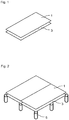
- Figure 1 shows a top view of a hollow-floor element, in this case a sheet-panelled access floor element, which consists of one first load-bearing panel 1 and one second load-bearing panel 3. Both individual panels 1, 3 are laid on top of each other and firmly joined together. The fixed connection is preferably accomplished by gluing the two individual panels together. It is, however possible, to use other ways of connecting the two panels such as by screwing, interlocking or other means known to the expert.
- the two load-bearing elements 1, 3 are gypsum fibreboards. It is of course also possible to produce a hollow-floor element from two or more panels of different materials firmly joined together.
- the two individual panels 1, 3 are superimposed and offset from one another. Due to the offset a defined overhang is produced on the longitudinal and/or the transverse sides of the hollow-floor element. This offset can be used for joining individual hollow-floor elements in a kind of tongue-and-groove joint together, thereby forming a contiguous floor.
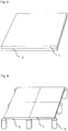
- Figure 2 shows a cut-out from a sheet-panelled access floor, where the hollow-floor elements of Fig. 1 are joined together in a kind of tongue-and-groove system. Individual hollow-floor elements are resting with their lower corners and edges on supports 5.
- the gypsum fibreboards which are used for manufacturing the hollow-floor elements shown in Figs. 1 and 2 each are 18 mm thick. This results in an overall thickness of 36 mm of the finished hollow-floor elements.
- the individual panels are manufactured by means of the dry process.
- a double-floor element which also consists of two individual panels 1, 3 firmly joined together, see Figs. 3, 4 .
- the double-floor elements are square-shaped, In order to remove them again at any time from the finished floor without efforts, the panels have smoothly polished slightly chamfered edges such that the floor surface comprises a bigger area than the floor lower surface.
- the individual panels 1, 3 lie flush on top of each other.
Description
- The invention relates to a method for manufacturing hollow-floor elements and to such elements. In particular the invention relates to hollow-floor panels manufactured from gypsum fibreboards.
- Hollow-floor panels (cavity flooring) are known in the art.
DE 40 21 963 A1 describes a hollow floor comprising individual support plates.US 5,632,848 describes a continuous manufacturing line for the preparation of gypsum fiberboards by means of a wet process. If a cavity is provided below the walk-on floor level, which is to be utilised for laying pipes and cables, the walk-on floor must have a support structure above the floor of the cavity. Such flooring is generally known as cavity flooring. Sheet-panelled access floors and raised access floors are hollow floors. The essential difference between sheet-panelled access floors and raised access floors consists in the way in which they are installed and in the size of their individual panels. - A raised access floor consists of individual elements which are easy to handle, and which at their edges or even at the corners rest on a support structure. Individual elements are connected with each other in a detachable or non-detachable manner. With sheet-panelled access floors, on the other hand, individual elements are connected among each other forming a contiguous floor body. Individual elements may be connected, for example, by means of a tongue-and-groove system, wherein a fixed connection may be achieved by screwing and/or gluing. In the case of sheet-panelled access floors individual elements are fixedly installed and can no longer be removed again. As a rule individual elements of sheet-panelled access floors are twice as large as individual elements of raised access floors.
- Since with sheet-panelled access flooring individual elements can no longer be removed without a great deal of effort and expense, these hollow floors have access hatches in order to cater for maintenance work to pipes or cables installed below the floor. The access hatches are normally provided in individual elements as recesses with a closable lid.
- A raised access floor is different from a sheet-panelled access floor in that it not only contains individual access hatches but in that all individual elements can in principle be removed again individually after the floor has been laid, in order to allow access to the cavity below the floor. Therefore access hatches are not necessary.
- So as to ensure that individual elements can be removed as easily as possible, individual elements are usually supported only in their corner and/or edge areas by the sub-structure. The support surface of individual elements is therefore very small, but it must nevertheless withstand heavy loads placed on it by for example heavy pieces of furniture. Therefore floor panels which are suitable for such raised access floors must comprise extremely high stability, i.e. be sufficiently robust and resistant to mechanical stresses in compliance with EN 12825.
- Hollow-floor panels or individual elements of the hollow floor may be manufactured from several materials, for example from gypsum fibreboard. Gypsum fibreboards may be produced in several ways, i.e. by means of a so-called dry, semi-dry or wet process.
- The stability of gypsum fibreboards can be generally increased in three different ways, i.e. the strength/thickness of the panels can be increased; the density of the panels can be increased; the panels may contain reinforcing materials.
- If dry or semi-dry processes are used for the manufacture of gypsum fibreboards, increasing the strength/thickness of the panels, however, is limited. When using the dry process, this is started by laying a carpet of dry fibres and dry calcium sulphate material (usually calcium sulphate semi-hydrate). This carpet is smoothed and sprayed with/soaked in the liquid constituents, mainly water and additives. Water is necessary for setting the gypsum, i.e. for converting the semi-hydrate into dihydrate. In order to achieve sufficient formability and a thorough soaking of the material, an excess of water is employed during the manufacture. This excess of water is sucked off to the fullest extent possible through the fibre gypsum carpet as it sets, the carpet is compressed into a panel shape and then dried.
- The method steps of soaking the semi-hydrate fibre carpet and of sucking off the surplus water limit the thickness of the panels, which can be produced by this process. The water must be able to soak the carpet right through, and a large proportion of the excess water must be able to be syphoned off in a relatively short time. Therefore, for the process to be economical, the thickness of the carpet is limited.
- A further problem occurs when the soaked gypsum fibre carpet is subsequently compressed. Since the fibres are not laid in an oriented manner but essentially randomly, compression of the carpet is economically viable only up to a certain panel thickness. Normally, if the panels are manufactured by the dry or semi-dry process, the maximum panel thickness is 25 mm. This thickness is not sufficient, however, for manufacturing sufficiently stable panels for use, in particular, in raised access flooring. The minimum breaking load required for double-floor panels has been laid down in the standard DIN EN 12825 and is divided into six element classes.
Class 1 stipulates a breaking load of larger than 4 kN; class 6 stipulates a breaking load of larger than 12 kN. - The DIN EN 13213 regulates the minimum requirements for sheet-panelled access floors correspondingly.
- The requirement of the invention consists in providing hollow-floor elements, in particular gypsum fibreboards, which are manufactured by the dry or semi-dry process.
- The requirement is met by a method for manufacturing a hollow-floor element according to
claim 1, which comprises al least two superimposed load-bearing individual panels, which when placed on top of each other are firmly joined together. - A hollow-floor element manufactured according to the invention may be either a sheet-panelled access floor panel for a contiguous hollow floor or a double-floor panel for a raised access floor.
- It is particularly advantageous if the superimposed individual panels of the hollow-floor element are bonded, interlocked or screwed to each other. In principle all types of individual panels known in the art, which are suitable for use in hollow flooring or raised access flooring, may be used. These may be, for example, gypsum fibreboards, laminated boards, cement-bonded fibre panels or cement-bonded laminated panels. Provision is also made according to the invention for different panel types to be combined with each other. Preferably, however, at least one individual panel consists of a gypsum fibreboard.
- A load-bearing individual panel is understood to be a panel, which essentially contributes to the stability of the panel and, mainly for this reason, i.e. for the creation of sufficient stability, is integrated with the hollow-floor element. In contrast thereto, hollow-floor elements may have coatings, which, for example, are applied to a hollow-floor element for reasons of optical appearance and/or for ensuring sufficient resistance to abrasion / chemical resistance. Such coatings are not be understood as load-bearing individual panels in terms of the invention. But coatings may of course be applied additionally to a hollow-floor element according to the invention or may additionally exist.
- The requirement is furthermore met by a hollow-floor element according to claim 7 comprising at least two superimposed load-bearing individual panels, wherein the at least two load-bearing panels are firmly connected with each other. Preferably individual panels are connected with each other by means of gluing, interlocking and/or screwing.
- The invention is particularly helpful in cases, in which the manufacture of the hollow-floor element is limited as regards the thickness of the panels. If one of the load-bearing panels is e.g. a gypsum fibreboard, which has been produced by way of a dry process or semi-dry process, this panel, according to the present state of the art, can be produced with a thickness of max. approx. 25 mm in order to give it sufficient strength. Therefore a preferred embodiment of the invention comprises load-bearing individual panels with a thickness of between 9 and 25 mm. Gypsum fibreboards of this thickness can be produced on known plants without problems by way of a dry process or semi-dry process. There is no need for a retrofit.
- It is, of course, also possible to firmly connect gypsum fibreboards with each other, which are produced by means of a wet process. Admittedly these gypsum fibreboards can be produced in greater thicknesses than those which are produced by way of a dry or semi-dry process. However, applications come to mind, in which even this greater thickness does not provide sufficient stability and a firm connection of the panels could solve this problem. Besides, the manufacture of thin panels is more economical than the manufacture of thick panels, wherefore connecting individual panels is more economical. The same is true, of course, for panels which are not gypsum fibreboards. These panels can also be advantageously firmly connected with each other in order to achieve sufficient stability in the overall bond.
- It is particularly preferred if the at least two individual panels of the hollow-floor element are connected offset from each other. For example the two individual panels can be connected with each other in such a way that none of the edges of the superimposed panels finishes flush with the edges of the respectively other individual panel. Preferably the edges of the respective individual panels extend however parallel to each other, and the offset of the panels relative to each other is defined. These results in a kind of tongue-and-groove system, which makes it easier to connect a number of hollow-floor elements to form a hollow-floor or a raised access floor.
- If the load-bearing individual panels are made from gypsum fibreboard, the following composition comprising at least the below-mentioned constituents, is preferred, i.e. a gypsum matrix with cellulose fibres and glass fibres.
- Especially preferably the gypsum matrix consists of 100% by weight or approx. 100% by weight dihydrate. Approx. 100% by weight means that only residual amounts of semi-hydrate, e.g. max. 5% by weight, may be present in the individual panel, after it is set. The gypsum matrix is obtained during manufacture from 80 to 95% by weight β-semi-hydrate and 5 to 20% by weight α-semi-hydrate, relative to the total amount of calcium sulphate semi-hydrate. The α-semi-hydrate is added in order to improve the dehydration of the calcium sulphate fibre carpet. α-semi-hydrate normally comprises larger crystals than β-semi-hydrate. The α-semi-hydrate crystals are extremely stable against grain decay when coming into contact with water. β-semi-hydrate by contrast is very susceptible to grain decay when coming into contact with water. The use of α-semi-hydrate permits the removal by suction of a large proportion of the excess water by a filter belt, which is not required for converting the semi-hydrate into dihydrate. Its purpose is therefore to improve dehydration. This dehydration improver is instrumental in achieving a higher raw density and thickness of the panel, which in turn improves the stability of the finished panel.
- According to a further preferred embodiment of the invention one gypsum fibre panel comprises cellulose fibres in an amount of 1 to 25% by weight, preferably 5 to 15% by weight and chopped glass fibres in an amount of 0.5 to 15% by weight, preferably 0.5 to 10% by weight and especially preferably 0.5 to 5% by weight, wherein the weightings refer to the mass of the mixture of all constituents. The glass fibres preferably have a length of 5 to 25 mm, preferably from 5 to 15 mm.
- Such a load-bearing individual panel is therefore manufactured from a mixture, comprising at least β-semi-hydrate, α-semi-hydrate as required, cellulose fibres, glass fibres and water. The cellulose fibres are preferably present in an amount of 1 to 25, especially preferably 5 to 15% by weight with reference to the total amount of the dry mixture.
- The glass fibres give additional toughness and stability to the gypsum fibreboard. The glass fibres may, for example, be chopped glass fibres, which are supplied in bunches of great length, also called rowing strands, which are chopped on site. What is essential for the manufacture of a bending-resistant and tension-resistant gypsum fibreboard, is the homogenous mixture of the dry constituents. The glass fibres must be chopped as required and then separated since they are functionally fully effective in the gypsum matrix only, if they have been separated.
- In addition to the described constituents commonly used additives such as retarders, rheology additives and similar can be added, which are known to the expert.
- The invention will now be explained in detail with reference to exemplary embodiments, in which:
- Fig. 1
- shows a top view of a sheet-panelled access floor element;
- Fig. 2
- shows a cut-out from a sheet-panelled access floor;
- Fig. 3
- shows a top view of a double-floor element;
- Fig. 4
- shows a cut-out from a double-floor.
-
Figure 1 shows a top view of a hollow-floor element, in this case a sheet-panelled access floor element, which consists of one first load-bearing panel 1 and one second load-bearing panel 3. Bothindividual panels - In this case the two load-
bearing elements - The two
individual panels -
Figure 2 shows a cut-out from a sheet-panelled access floor, where the hollow-floor elements ofFig. 1 are joined together in a kind of tongue-and-groove system. Individual hollow-floor elements are resting with their lower corners and edges on supports 5. - The gypsum fibreboards, which are used for manufacturing the hollow-floor elements shown in
Figs. 1 and 2 each are 18 mm thick. This results in an overall thickness of 36 mm of the finished hollow-floor elements. The individual panels are manufactured by means of the dry process. - Individual panels are manufactured by mixing the following dry constituents together:
β-semi-hydrate 80% by weight with reference to the total calcium sulphate content α-semi-hydrate 20% by weight with reference to the total calcium sulphate content cellulose fibres 9% by weight with reference to all dry constituents glass fibres 3% by weight with reference to all dry constituents, length: 8 mm - Two individual panels manufactured from this mixture are respectively arranged on top of each other and glued together. The hollow-floor elements produced in this way have a breaking load of > 6 kN, tested in accordance with DIN EN 13213.
- The same material was used to manufacture a double-floor element, which also consists of two
individual panels Figs. 3, 4 . In contrast to the sheet-panelled access elements shown inFigs. 1 and 2 the double-floor elements are square-shaped, In order to remove them again at any time from the finished floor without efforts, the panels have smoothly polished slightly chamfered edges such that the floor surface comprises a bigger area than the floor lower surface. Theindividual panels
Claims (13)
- A method for manufacturing a hollow-floor element, comprising at least two superimposed load-bearing individual panels (1.3), the method comprising laying at least two load-bearing individual panels (1,3) on top of each other and firmly joining the at least two load-bearing individual panels (1.3) together, in particular by gluing, wherein at least one of the load-bearing individual panels (1,3) is a gypsum fibreboard comprising a gypsum matrix, characterized in that said method comprises the step of manufacturing said gypsum matrix of the gypsum fibreboard from 80 to 95% by weight calcium sulphate β-semi-hydrate and 5 to 20% by weight calcium sulphate α-semi-hydrate, relative to the total amount of the calcium sulphate semi-hydrate.
- The method according to claim 1, wherein said gypsum fibreboard is manufactured by means of a dry process or semi-dry process.
- The method according to claim 2, wherein the at least one load-bearing individual panel (1,3) is manufactured from a mixture, comprising at least β-semi-hydrate, α-semi-hydrate as required, cellulose fibres, glass fibres and water.
- The method according to claim 3, wherein the mixture for manufacturing the at least one load-bearing individual panel (1,3) comprises β-semi-hydrate in an amount of 80 to 95%by weight, α-semi-hydrate in an amount of 5 to 20% by weight, with reference to the total amount of the calcium sulphate.
- The method according to claim 3 or 4, wherein cellulose fibres in an amount of 1 to 25% by weight and chopped glass fibres in an amount of 0.5 to 15% by weight with reference to the mixture of all dry constituents are added to the mixture for manufacturing the at least one load-bearing individual panel (1,3), the chopped glass fibres preferably having a length of between 5 and 25 mm.
- The method according to one of claims 1 to 5, wherein the method comprises firmly joining the at least two individual panels (1,3) together offset from each other.
- A hollow-floor element for use in a hollow floor, wherein the hollow-floor element manufactured according to claim 1 comprises at least two superimposed load-bearing individual panels (1,3) which are firmly joined, in particular glued, to each other, wherein at least one of the load-bearing individual panels (1, 3) is a gypsum fibreboard comprising a gypsum matrix, characterised in that the gypsum matrix is obtained during manufacturing of the gypsum fibreboard from 80 to 95% by weight calcium sulphate β-semi-hydrate and 5 to 20% by weight calcium sulphate α-semi-hydrate, relative to the total amount of the calcium sulphate semi-hydrate.
- The hollow-floor element according to claim 7, wherein the load-bearing individual panels (1,3) each have a thickness of between 9 and 25 mm.
- The hollow-floor element according to claim 7, wherein the gypsum matrix comprises cellulose fibres and glass fibres.
- The hollow-floor element according to claim 9, characterised in that the at least one individual panel (1,3) comprises cellulose fibres in an amount of 1 to 25% by weight and chopped glass fibres in an amount of 0.5 to 15% by weight, wherein the weightings refer to the mixture of all constituents.
- The hollow-floor element according to claim 9 or 10, wherein the glass fibres have a length of between 5 and 25 mm.
- The hollow-floor element according to one of claims 7-11, wherein the individual panels (1,3) are manufactured by means of a dry process or a semi-dry process.
- The hollow-floor element according to one of claims 7-12, wherein the at least two individual panels are joined firmly together offset from each other.
Priority Applications (1)
| Application Number | Priority Date | Filing Date | Title |
|---|---|---|---|
| PL16732936T PL3322864T3 (en) | 2015-07-15 | 2016-05-25 | Hollow-floor elements and method for manufacturing a hollow-floor element |
Applications Claiming Priority (3)
| Application Number | Priority Date | Filing Date | Title |
|---|---|---|---|
| DE102015008916 | 2015-07-15 | ||
| DE102015009280 | 2015-07-21 | ||
| PCT/EP2016/000867 WO2017008869A1 (en) | 2015-07-15 | 2016-05-25 | Hollow-floor elements and method for manufacturing a hollow-floor element |
Publications (2)
| Publication Number | Publication Date |
|---|---|
| EP3322864A1 EP3322864A1 (en) | 2018-05-23 |
| EP3322864B1 true EP3322864B1 (en) | 2021-07-21 |
Family
ID=56289448
Family Applications (1)
| Application Number | Title | Priority Date | Filing Date |
|---|---|---|---|
| EP16732936.6A Active EP3322864B1 (en) | 2015-07-15 | 2016-05-25 | Hollow-floor elements and method for manufacturing a hollow-floor element |
Country Status (4)
| Country | Link |
|---|---|
| US (1) | US20180127988A1 (en) |
| EP (1) | EP3322864B1 (en) |
| PL (1) | PL3322864T3 (en) |
| WO (1) | WO2017008869A1 (en) |
Families Citing this family (1)
| Publication number | Priority date | Publication date | Assignee | Title |
|---|---|---|---|---|
| US10550585B1 (en) * | 2018-10-23 | 2020-02-04 | Gold Water International Inc. | Assemblable platform made of fiber-reinforced plastic (FRP) |
Family Cites Families (6)
| Publication number | Priority date | Publication date | Assignee | Title |
|---|---|---|---|---|
| DE1805126C3 (en) * | 1968-10-25 | 1975-05-28 | H. & E. Boergardts Kg, 3425 Walkenried | Mass for the production of working forms for the ceramic industry |
| US5632848A (en) * | 1989-10-12 | 1997-05-27 | Georgia-Pacific Corporation | Continuous processing equipment for making fiberboard |
| DE4021963A1 (en) * | 1990-07-10 | 1992-01-16 | Lindner Ag | Hollow floor in building - comprises individual plates on height-adjustable supports |
| US8850770B2 (en) * | 2001-06-21 | 2014-10-07 | Roger C. Roen | Structurally integrated accessible floor system |
| EP1304425B1 (en) * | 2001-10-18 | 2006-04-05 | Bresciana Graniti S.p.A. | Composite panel for raised floors |
| WO2016101968A1 (en) * | 2014-12-22 | 2016-06-30 | Knauf Gips Kg | Gypsum fiber board and method for producing gypsum fiber boards |
-
2016
- 2016-05-25 WO PCT/EP2016/000867 patent/WO2017008869A1/en active Application Filing
- 2016-05-25 PL PL16732936T patent/PL3322864T3/en unknown
- 2016-05-25 EP EP16732936.6A patent/EP3322864B1/en active Active
-
2018
- 2018-01-10 US US15/867,294 patent/US20180127988A1/en not_active Abandoned
Non-Patent Citations (1)
| Title |
|---|
| None * |
Also Published As
| Publication number | Publication date |
|---|---|
| EP3322864A1 (en) | 2018-05-23 |
| WO2017008869A1 (en) | 2017-01-19 |
| PL3322864T3 (en) | 2021-11-29 |
| US20180127988A1 (en) | 2018-05-10 |
Similar Documents
| Publication | Publication Date | Title |
|---|---|---|
| MX2010013470A (en) | Method for producing panels and panel produced according to the method. | |
| TR201808911T4 (en) | Composite plate made of wood. | |
| EP3322864B1 (en) | Hollow-floor elements and method for manufacturing a hollow-floor element | |
| JP2005502800A (en) | Architectural tile | |
| CN213859758U (en) | Integrated board with high strength | |
| CN2774769Y (en) | Decorative wooden board of bamboo-wood composite structure | |
| CN101748880A (en) | Solid wood composite floor board baseplate and manufacturing method thereof | |
| CN111114029A (en) | Wooden heart finger-jointed board and manufacturing method thereof | |
| EP0884152A1 (en) | A slab of stone material with multiple layer paper and phenolic resin-based backing, and method for making slab | |
| CN210508224U (en) | Multilayer processing composite board convenient to process | |
| EP1364774B1 (en) | Prefabricated parquet with sound insulation | |
| CN207332214U (en) | Impregnated paper laminated multilayer floor | |
| CN207332206U (en) | Finger connects Waterproof Wooden Floor Block | |
| CN210459872U (en) | Three-layer solid wood composite floor with composite structure | |
| Лапина et al. | Advantages and disadvantages of cross-laminated timber in modern construsction | |
| AT6643U1 (en) | MOBILE FLOOR | |
| RU2357053C2 (en) | Construction panel with decorative finish | |
| CN208614986U (en) | A kind of particieboard structure of retarded combustion rate | |
| JP5073086B2 (en) | Surface materials and building materials | |
| US20130199119A1 (en) | Board and Batten Siding System | |
| US20220018128A1 (en) | Building panel with sections | |
| CN107186830A (en) | Container or vehicle floor and its manufacture method | |
| CN1148502C (en) | Fire-proof plate and its making method | |
| CN114211576A (en) | Preparation method of high-strength composite engineering bamboo material | |
| EP1596028A2 (en) | Floor made of plates of floor cement and construction set for its generation |
Legal Events
| Date | Code | Title | Description |
|---|---|---|---|
| STAA | Information on the status of an ep patent application or granted ep patent |
Free format text: STATUS: THE INTERNATIONAL PUBLICATION HAS BEEN MADE |
|
| PUAI | Public reference made under article 153(3) epc to a published international application that has entered the european phase |
Free format text: ORIGINAL CODE: 0009012 |
|
| STAA | Information on the status of an ep patent application or granted ep patent |
Free format text: STATUS: REQUEST FOR EXAMINATION WAS MADE |
|
| 17P | Request for examination filed |
Effective date: 20180117 |
|
| AK | Designated contracting states |
Kind code of ref document: A1 Designated state(s): AL AT BE BG CH CY CZ DE DK EE ES FI FR GB GR HR HU IE IS IT LI LT LU LV MC MK MT NL NO PL PT RO RS SE SI SK SM TR |
|
| AX | Request for extension of the european patent |
Extension state: BA ME |
|
| DAV | Request for validation of the european patent (deleted) | ||
| DAX | Request for extension of the european patent (deleted) | ||
| STAA | Information on the status of an ep patent application or granted ep patent |
Free format text: STATUS: EXAMINATION IS IN PROGRESS |
|
| 17Q | First examination report despatched |
Effective date: 20190212 |
|
| STAA | Information on the status of an ep patent application or granted ep patent |
Free format text: STATUS: EXAMINATION IS IN PROGRESS |
|
| REG | Reference to a national code |
Ref country code: DE Ref legal event code: R079 Ref document number: 602016060899 Country of ref document: DE Free format text: PREVIOUS MAIN CLASS: E04F0015024000 Ipc: E04F0015080000 |
|
| RIC1 | Information provided on ipc code assigned before grant |
Ipc: E04F 15/024 20060101ALI20201127BHEP Ipc: E04F 15/08 20060101AFI20201127BHEP |
|
| GRAP | Despatch of communication of intention to grant a patent |
Free format text: ORIGINAL CODE: EPIDOSNIGR1 |
|
| STAA | Information on the status of an ep patent application or granted ep patent |
Free format text: STATUS: GRANT OF PATENT IS INTENDED |
|
| INTG | Intention to grant announced |
Effective date: 20210201 |
|
| GRAS | Grant fee paid |
Free format text: ORIGINAL CODE: EPIDOSNIGR3 |
|
| GRAA | (expected) grant |
Free format text: ORIGINAL CODE: 0009210 |
|
| STAA | Information on the status of an ep patent application or granted ep patent |
Free format text: STATUS: THE PATENT HAS BEEN GRANTED |
|
| AK | Designated contracting states |
Kind code of ref document: B1 Designated state(s): AL AT BE BG CH CY CZ DE DK EE ES FI FR GB GR HR HU IE IS IT LI LT LU LV MC MK MT NL NO PL PT RO RS SE SI SK SM TR |
|
| REG | Reference to a national code |
Ref country code: GB Ref legal event code: FG4D |
|
| REG | Reference to a national code |
Ref country code: CH Ref legal event code: EP |
|
| REG | Reference to a national code |
Ref country code: DE Ref legal event code: R096 Ref document number: 602016060899 Country of ref document: DE |
|
| REG | Reference to a national code |
Ref country code: AT Ref legal event code: REF Ref document number: 1412750 Country of ref document: AT Kind code of ref document: T Effective date: 20210815 |
|
| REG | Reference to a national code |
Ref country code: IE Ref legal event code: FG4D |
|
| REG | Reference to a national code |
Ref country code: LT Ref legal event code: MG9D |
|
| REG | Reference to a national code |
Ref country code: NL Ref legal event code: MP Effective date: 20210721 |
|
| PG25 | Lapsed in a contracting state [announced via postgrant information from national office to epo] |
Ref country code: LT Free format text: LAPSE BECAUSE OF FAILURE TO SUBMIT A TRANSLATION OF THE DESCRIPTION OR TO PAY THE FEE WITHIN THE PRESCRIBED TIME-LIMIT Effective date: 20210721 Ref country code: NL Free format text: LAPSE BECAUSE OF FAILURE TO SUBMIT A TRANSLATION OF THE DESCRIPTION OR TO PAY THE FEE WITHIN THE PRESCRIBED TIME-LIMIT Effective date: 20210721 Ref country code: NO Free format text: LAPSE BECAUSE OF FAILURE TO SUBMIT A TRANSLATION OF THE DESCRIPTION OR TO PAY THE FEE WITHIN THE PRESCRIBED TIME-LIMIT Effective date: 20211021 Ref country code: PT Free format text: LAPSE BECAUSE OF FAILURE TO SUBMIT A TRANSLATION OF THE DESCRIPTION OR TO PAY THE FEE WITHIN THE PRESCRIBED TIME-LIMIT Effective date: 20211122 Ref country code: FI Free format text: LAPSE BECAUSE OF FAILURE TO SUBMIT A TRANSLATION OF THE DESCRIPTION OR TO PAY THE FEE WITHIN THE PRESCRIBED TIME-LIMIT Effective date: 20210721 Ref country code: ES Free format text: LAPSE BECAUSE OF FAILURE TO SUBMIT A TRANSLATION OF THE DESCRIPTION OR TO PAY THE FEE WITHIN THE PRESCRIBED TIME-LIMIT Effective date: 20210721 Ref country code: HR Free format text: LAPSE BECAUSE OF FAILURE TO SUBMIT A TRANSLATION OF THE DESCRIPTION OR TO PAY THE FEE WITHIN THE PRESCRIBED TIME-LIMIT Effective date: 20210721 Ref country code: SE Free format text: LAPSE BECAUSE OF FAILURE TO SUBMIT A TRANSLATION OF THE DESCRIPTION OR TO PAY THE FEE WITHIN THE PRESCRIBED TIME-LIMIT Effective date: 20210721 Ref country code: RS Free format text: LAPSE BECAUSE OF FAILURE TO SUBMIT A TRANSLATION OF THE DESCRIPTION OR TO PAY THE FEE WITHIN THE PRESCRIBED TIME-LIMIT Effective date: 20210721 |
|
| PG25 | Lapsed in a contracting state [announced via postgrant information from national office to epo] |
Ref country code: LV Free format text: LAPSE BECAUSE OF FAILURE TO SUBMIT A TRANSLATION OF THE DESCRIPTION OR TO PAY THE FEE WITHIN THE PRESCRIBED TIME-LIMIT Effective date: 20210721 Ref country code: GR Free format text: LAPSE BECAUSE OF FAILURE TO SUBMIT A TRANSLATION OF THE DESCRIPTION OR TO PAY THE FEE WITHIN THE PRESCRIBED TIME-LIMIT Effective date: 20211022 |
|
| REG | Reference to a national code |
Ref country code: DE Ref legal event code: R097 Ref document number: 602016060899 Country of ref document: DE |
|
| PG25 | Lapsed in a contracting state [announced via postgrant information from national office to epo] |
Ref country code: DK Free format text: LAPSE BECAUSE OF FAILURE TO SUBMIT A TRANSLATION OF THE DESCRIPTION OR TO PAY THE FEE WITHIN THE PRESCRIBED TIME-LIMIT Effective date: 20210721 |
|
| PLBE | No opposition filed within time limit |
Free format text: ORIGINAL CODE: 0009261 |
|
| STAA | Information on the status of an ep patent application or granted ep patent |
Free format text: STATUS: NO OPPOSITION FILED WITHIN TIME LIMIT |
|
| PG25 | Lapsed in a contracting state [announced via postgrant information from national office to epo] |
Ref country code: SM Free format text: LAPSE BECAUSE OF FAILURE TO SUBMIT A TRANSLATION OF THE DESCRIPTION OR TO PAY THE FEE WITHIN THE PRESCRIBED TIME-LIMIT Effective date: 20210721 Ref country code: SK Free format text: LAPSE BECAUSE OF FAILURE TO SUBMIT A TRANSLATION OF THE DESCRIPTION OR TO PAY THE FEE WITHIN THE PRESCRIBED TIME-LIMIT Effective date: 20210721 Ref country code: RO Free format text: LAPSE BECAUSE OF FAILURE TO SUBMIT A TRANSLATION OF THE DESCRIPTION OR TO PAY THE FEE WITHIN THE PRESCRIBED TIME-LIMIT Effective date: 20210721 Ref country code: EE Free format text: LAPSE BECAUSE OF FAILURE TO SUBMIT A TRANSLATION OF THE DESCRIPTION OR TO PAY THE FEE WITHIN THE PRESCRIBED TIME-LIMIT Effective date: 20210721 Ref country code: CZ Free format text: LAPSE BECAUSE OF FAILURE TO SUBMIT A TRANSLATION OF THE DESCRIPTION OR TO PAY THE FEE WITHIN THE PRESCRIBED TIME-LIMIT Effective date: 20210721 Ref country code: AL Free format text: LAPSE BECAUSE OF FAILURE TO SUBMIT A TRANSLATION OF THE DESCRIPTION OR TO PAY THE FEE WITHIN THE PRESCRIBED TIME-LIMIT Effective date: 20210721 |
|
| 26N | No opposition filed |
Effective date: 20220422 |
|
| PG25 | Lapsed in a contracting state [announced via postgrant information from national office to epo] |
Ref country code: IT Free format text: LAPSE BECAUSE OF FAILURE TO SUBMIT A TRANSLATION OF THE DESCRIPTION OR TO PAY THE FEE WITHIN THE PRESCRIBED TIME-LIMIT Effective date: 20210721 |
|
| REG | Reference to a national code |
Ref country code: BE Ref legal event code: MM Effective date: 20220531 |
|
| GBPC | Gb: european patent ceased through non-payment of renewal fee |
Effective date: 20220525 |
|
| PG25 | Lapsed in a contracting state [announced via postgrant information from national office to epo] |
Ref country code: MC Free format text: LAPSE BECAUSE OF FAILURE TO SUBMIT A TRANSLATION OF THE DESCRIPTION OR TO PAY THE FEE WITHIN THE PRESCRIBED TIME-LIMIT Effective date: 20210721 Ref country code: LU Free format text: LAPSE BECAUSE OF NON-PAYMENT OF DUE FEES Effective date: 20220525 |
|
| REG | Reference to a national code |
Ref country code: AT Ref legal event code: UEP Ref document number: 1412750 Country of ref document: AT Kind code of ref document: T Effective date: 20210721 |
|
| PG25 | Lapsed in a contracting state [announced via postgrant information from national office to epo] |
Ref country code: IE Free format text: LAPSE BECAUSE OF NON-PAYMENT OF DUE FEES Effective date: 20220525 Ref country code: FR Free format text: LAPSE BECAUSE OF NON-PAYMENT OF DUE FEES Effective date: 20220531 |
|
| PG25 | Lapsed in a contracting state [announced via postgrant information from national office to epo] |
Ref country code: GB Free format text: LAPSE BECAUSE OF NON-PAYMENT OF DUE FEES Effective date: 20220525 Ref country code: BE Free format text: LAPSE BECAUSE OF NON-PAYMENT OF DUE FEES Effective date: 20220531 |
|
| PGFP | Annual fee paid to national office [announced via postgrant information from national office to epo] |
Ref country code: DE Payment date: 20230530 Year of fee payment: 8 Ref country code: CH Payment date: 20230610 Year of fee payment: 8 Ref country code: BG Payment date: 20230511 Year of fee payment: 8 |
|
| PGFP | Annual fee paid to national office [announced via postgrant information from national office to epo] |
Ref country code: PL Payment date: 20230502 Year of fee payment: 8 Ref country code: AT Payment date: 20230504 Year of fee payment: 8 |
|
| P01 | Opt-out of the competence of the unified patent court (upc) registered |
Effective date: 20230822 |
|
| PG25 | Lapsed in a contracting state [announced via postgrant information from national office to epo] |
Ref country code: HU Free format text: LAPSE BECAUSE OF FAILURE TO SUBMIT A TRANSLATION OF THE DESCRIPTION OR TO PAY THE FEE WITHIN THE PRESCRIBED TIME-LIMIT; INVALID AB INITIO Effective date: 20160525 |