EP3322489B1 - Pressure regulator assembly and bypass assembly for a self-contained breathing apparatus - Google Patents
Pressure regulator assembly and bypass assembly for a self-contained breathing apparatus Download PDFInfo
- Publication number
- EP3322489B1 EP3322489B1 EP16823811.1A EP16823811A EP3322489B1 EP 3322489 B1 EP3322489 B1 EP 3322489B1 EP 16823811 A EP16823811 A EP 16823811A EP 3322489 B1 EP3322489 B1 EP 3322489B1
- Authority
- EP
- European Patent Office
- Prior art keywords
- piston
- assembly
- pressure regulator
- bypass
- air
- Prior art date
- Legal status (The legal status is an assumption and is not a legal conclusion. Google has not performed a legal analysis and makes no representation as to the accuracy of the status listed.)
- Active
Links
Images

Classifications
-
- A—HUMAN NECESSITIES
- A62—LIFE-SAVING; FIRE-FIGHTING
- A62B—DEVICES, APPARATUS OR METHODS FOR LIFE-SAVING
- A62B9/00—Component parts for respiratory or breathing apparatus
- A62B9/02—Valves
- A62B9/022—Breathing demand regulators
- A62B9/025—Breathing demand regulators with tilting opening action
-
- A—HUMAN NECESSITIES
- A62—LIFE-SAVING; FIRE-FIGHTING
- A62B—DEVICES, APPARATUS OR METHODS FOR LIFE-SAVING
- A62B7/00—Respiratory apparatus
- A62B7/02—Respiratory apparatus with compressed oxygen or air
- A62B7/04—Respiratory apparatus with compressed oxygen or air and lung-controlled oxygen or air valves
-
- B—PERFORMING OPERATIONS; TRANSPORTING
- B63—SHIPS OR OTHER WATERBORNE VESSELS; RELATED EQUIPMENT
- B63C—LAUNCHING, HAULING-OUT, OR DRY-DOCKING OF VESSELS; LIFE-SAVING IN WATER; EQUIPMENT FOR DWELLING OR WORKING UNDER WATER; MEANS FOR SALVAGING OR SEARCHING FOR UNDERWATER OBJECTS
- B63C11/00—Equipment for dwelling or working underwater; Means for searching for underwater objects
- B63C11/02—Divers' equipment
- B63C11/18—Air supply
- B63C11/22—Air supply carried by diver
- B63C11/2227—Second-stage regulators
Definitions
- This invention relates generally to a pressure regulator assembly for use with a mask or helmet, such as a breathing mask or helmet used in connection with a self-contained breathing apparatus.
- SCBA self-contained breathing apparatus
- SCBA typically includes one or more compressed air tanks or cylinders fluidly connected to a breathing mask or helmet.
- SCBAs are often used in firefighting activities when the firefighter is engaged in activities in a smoky environment.
- a SCBA normally includes a two-stage pressure reduction process through which the pressure of the output air from the compressed air tank or cylinder is regulated in stages to a desired breathing pressure.
- positive pressure-type firefighting pressure regulator and mask assemblies such as typically disclosed in US 2004/261794 A1 , which use a positive pressure-type air supply valve, exhibit various drawbacks and deficiencies, including: (1) difficulty and complexity in assembly that often requires optimizing during and after assembly and prior to use in normal operation; (2) introduction of a valve chatter that often occurs when an air supply valve is in use, where such a chatter cannot be completely eliminated during the optimizing process; (3) a high breathing resistance and unstable pressure reduction, particularly in a low-temperature environment where leakage and breathing difficulty can have a high occurrence rate; and (4) high complexity in operation, bulky volume, and increased weight, such that these existing systems and assemblies require the use of two hands in cooperation to handle and operate.
- an improved pressure regulator assembly for use in connection with a breathing mask or helmet in a self-contained breathing apparatus.
- an improved pressure regulator assembly that is durable, comfortable, and easy in assembly and operation.
- an improved regulator assembly that is useful in connection with a positive pressure-type air supply valve and system.
- an improved bypass assembly for use with a pressure regulator assembly in a self-contained breathing apparatus.
- a pressure regulator according to claim 1.
- valve assembly further comprises at least one biasing element positioned in the cavity and configured to urge the first end of the piston into engagement with the sealing member.
- at least one biasing element comprises at least one spring.
- the second end of the piston comprises a recess configured to receive at least a portion of the at least one biasing element.
- the valve assembly further comprises at least one passage at least partially enclosing the cylinder and an external surface of the first end of the piston to facilitate fluid communication between the inlet chamber and the outlet chamber when the first end of the piston is disengaged from the sealing member.
- the width of the passage is in the range of about 0.7 mm to about 1.2 mm, and a diameter of an inlet portion of the outlet chamber is in the range of about 8.8 mm to about 9.6 mm.
- the width of the passage is about 1.0 mm and the diameter of the inlet portion of the outlet chamber is about 9.0 mm.
- the inlet chamber extends in a first direction and the outlet chamber extends in a second direction, wherein the first direction is angled with respect to the second direction. In another preferred and non-limiting embodiment or aspect, the angle is about 90°.
- the pressure regulator comprises a bypass assembly configured to be removably attached to the pressure regulator assembly and configured to disengage the first end of the piston from the sealing member and facilitate the flow of air through the valve assembly and into the outlet chamber.
- This bypass assembly comprises: a bypass housing defining a bypass inlet, a bypass outlet, and a fluid passage extending between the bypass inlet and the bypass outlet; and a push rod having a first end configured to contact the first end of the piston and disengage the first end of the piston from the sealing member, such that air in the fluid passage of the bypass housing flows through the valve assembly and into the outlet chamber.
- This pressure regulator assembly comprises a rotatable member rotatably connected to the bypass housing, wherein when the rotatable member is rotated in a first direction, the push rod is urged toward and in contact with the first end of the piston to thereby disengage the first end of the piston and the sealing member, and wherein the rotatable member is rotated in a second direction, the push rod is urged away from and out of contact with the first end of the piston to thereby permit reengagement of the first end of the piston with the sealing member.
- the rotatable member comprises: a recess extending into a body of the rotatable member; and a cover positioned at least partially within the recess and engaged with a second end of the push rod, such that when the rotatable member is rotated in the first direction, the cover, and thereby the push rod, is urged toward and into contact with the first end of the piston to thereby disengage the first end of the piston and the sealing member.
- the bypass assembly is adjustable to thereby adjust the amount of the flow of air through the bypass assembly, through the valve assembly, and into the outlet chamber.
- a bypass assembly for a pressure regulator assembly having: (i) a valve assembly positioned between an inlet chamber and an outlet chamber and including: a piston having a body with a first end and a second end; and a sealing member configured for engagement by the first end of the piston, wherein, when the first end of the piston engages the sealing member, air is prevented from exiting the inlet chamber, and when the first end of the piston is disengaged from the sealing member, air is capable of exiting the inlet chamber; and (ii) a driving assembly coupled to the valve assembly and configured to facilitate the engagement and disengagement of the piston responsive to a change of pressure in the outlet chamber, the bypass assembly configured to be removably attached to the pressure regulator assembly and configured to disengage the first end of the piston from the sealing member and facilitate the flow of air through the valve assembly and into the outlet chamber.
- the bypass assembly comprises: a bypass housing defining a bypass inlet, a bypass outlet, and a fluid passage extending between the bypass inlet and the bypass outlet; and a push rod having a first end configured to contact the first end of the piston and disengage the first end of the piston from the sealing member, such that air in the fluid passage of the bypass housing flows through the valve assembly and into the outlet chamber.
- the bypass assembly further comprises a rotatable member rotatably connected to the bypass housing, wherein when the rotatable member is rotated in a first direction, the push rod is urged toward and in contact with the first end of the piston to thereby disengage the first end of the piston and the sealing member, and wherein the rotatable member is rotated in a second direction, the push rod is urged away from and out of contact with the first end of the piston to thereby permit reengagement of the first end of the piston with the sealing member.
- the rotatable member comprises: a recess extending into a body of the rotatable member; and a cover positioned at least partially within the recess and engaged with a second end of the push rod, such that when the rotatable member is rotated in the first direction, the cover, and thereby the push rod, is urged toward and into contact with the first end of the piston to thereby disengage the first end of the piston and the sealing member.
- the pressure regulator assembly further comprises: a cylinder configured to receive the second end of the piston and defining a cavity between an end of the cylinder and the second end of the piston; and a conduit extending through the body of the piston and facilitating fluid communication between the inlet chamber and the cavity.
- a self-contained breathing apparatus comprising: at least one air cylinder configured to deliver regulated air through an air hose; and a breathing mask configured to be worn by a user, the breathing mask having a pressure regulator assembly configured to deliver air from the air hose to an internal area of the mask, wherein the pressure regulator assembly comprises: (a) a housing defining an inlet chamber in fluid communication with an outlet chamber; and (b) a valve assembly positioned between the inlet chamber and the outlet chamber, the valve assembly comprising: (i) a piston having a body with a first end and a second end; (ii) a cylinder configured to receive the second end of the piston and defining a cavity between an end of the cylinder and the second end of the piston; (iii) a sealing member configured for engagement by the first end of the piston, wherein, when the first end of the piston engages the sealing member, air is prevented from exiting the inlet chamber, and when the first end of the piston is disengaged
- a pressure regulator assembly comprising: an inlet and an outlet; a housing defining a first chamber in fluid communication with the inlet and a second chamber in fluid communication with the outlet; a valve assembly disposed between the first chamber and the second chamber, the valve assembly including: a piston having a first end and a second end opposite to the first end; a cylinder configured to receive the second end of the piston to define a cavity between the cylinder and the second end of the piston; and a sealing element disposed adjacent to the first end of the piston; wherein the piston has a through-hole disposed thereon to communicate the first end and the second end of the piston so as to allow fluid in the first chamber to flow into the cavity via the through-hole; and a driving assembly coupled to the valve assembly and configured to drive the piston to engage with the sealing element or move away from the sealing element in response to change of pressure in the second chamber.
- valve assembly further comprises a biasing element disposed within the cavity and configured to bias the piston towards the sealing element.
- the second end of the piston has a recess to receive at least a part of the biasing element.
- the valve assembly further comprises a passage at least partially enclosing the cylinder and an external surface of the first end of the piston to allow fluid from the inlet to flow into the first chamber, then flow into the second chamber through the passage and reach the outlet when the piston is driven to move away from the sealing element.
- a size of the passage is in the range of 0.7 mm to 1.2 mm, and a diameter of the second chamber is in the range of 8.8 mm to 9.6 mm.
- the size of the passage is 1.0 mm, and the diameter of the second chamber is 9.0 mm.
- the first chamber is disposed along a fluid-in direction
- the second chamber is disposed along a fluid-out direction
- the fluid-in direction being angled with the fluid-out direction.
- the fluid-in direction is perpendicular to the fluid-out direction.
- the pressure regulator assembly further comprises a bypass device coupled to the pressure regulator assembly, the bypass device comprising: a bypass housing defining a bypass inlet, a bypass outlet and a fluid passage between the bypass inlet and the bypass outlet; and a push rod, a first end of which is disposed adjacent the piston and configured to drive the piston to move away from the sealing element so as to fluidly communicate the fluid passage and the pressure regulator assembly.
- the bypass device further comprises: a handwheel operatively coupled to the bypass housing and having a concave portion; and a cover received within the concave portion; wherein a second end of the push rod extends through the housing and is fixedly connected to the cover such that the push rod could move towards the piston or move away from the piston by adjusting the handwheel.
- the present invention is directed to a pressure regulator assembly 100 and a bypass assembly 120 for a pressure regulator assembly for use with a self-contained breathing apparatus (SCBA).
- SCBA self-contained breathing apparatus
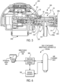
- the self-contained breathing apparatus (SCBA) includes at least one air cylinder (AC) configured or operable to deliver regulated air through an air hose (not shown) and a breathing mask or helmet (M) configured to be worn by a user.
- the breathing mask or helmet (M) includes a pressure regulator assembly (such as the existing pressure regulator assembly illustrated in Fig. 1 or the pressure regulator assembly 100 according to the principles of the present invention) configured to deliver air from the air hose to an internal area (IA) of the breathing mask or helmet (M).
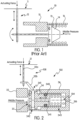
- Fig. 1 is a schematic diagram of an existing air supply valve assembly 10 in a pressure regulator for use in a self-contained breathing apparatus.
- the valve assembly 10 includes a diaphragm 11, a lever 12, a reset spring 13, a piston 14, a valve seat 15, and a cylinder 16, wherein the diaphragm 11 drives the piston 14 via the lever 12.
- the lever 12 When an actuating force is applied to the lever 12 via the diaphragm 11, the lever 12 will urge or push the piston 14 to disengage the valve seat 15, thereby opening the valve assembly to form a fluid passage (and deliver air to the breathing mask or helmet).
- valve assembly 102 for the pressure regulator assembly 100 is illustrated in schematic form in Fig. 2 .
- the pressure regulator assembly 100 according to the present invention includes a balanced valve assembly 102, wherein the valve assembly 102 facilitates the controlled passage of air through the pressure regulator assembly 100.
- the valve assembly 102 includes: (i) a piston 34 having a body 340 with a first end 342 and a second end 343 opposite the first end 342; (ii) a cylinder 36 configured to receive the second end 343 of the piston 34 and defining a cavity 104 between an end 106 of the cylinder 36 and the second end 343 of the piston 34; (iii) a sealing member (or element) 35 configured for engagement by the first end 342 of the piston 34; and (iv) a conduit 241 (or through-hole) extending through the body 340 of the piston 34 and facilitating or providing fluid communication between an air inlet and the cavity 104.
- the pressure regulator assembly 100 includes a driving assembly 108 coupled to or operatively associated with the piston 34 and configured to facilitate or cause the engagement and/or disengagement of the piston 34 responsive to a change of pressure in an air outlet of the pressure regulator assembly 100.
- the drive assembly 100 may include a diaphragm 31, which, when acted on by an actuating force (or pressure) causes the driving assembly 108 (such as a first lever 32a and a second lever 32b) to disengage the first end 342 of the piston 34 from a sealing member 25. This operation, in turn opens the valve assembly 102 to form a fluid passage between an air inlet to an air outlet.
- the conduit 241 provides fluid communication of air between the area (e.g., a middle-pressure chamber or area) in front of the piston 34 and the cavity 104 formed at the rear of the piston 34. Since both of the ends or areas of the piston 34 are in fluid communication with each other, the air outside of the cylinder 36 can flow into the cavity 104 of the cylinder 36 through the conduit 241. Accordingly, and since the middle-pressure air pressure exists in surfaces or areas of both sides of the piston 34, the acting forces generated by the air pressures at the front and rear sides of the piston 34 counteract during operation of the pressure regulator assembly 100, such that the air pressure acting on the piston 34 is close to zero.
- the middle-pressure air pressure exists in surfaces or areas of both sides of the piston 34, the acting forces generated by the air pressures at the front and rear sides of the piston 34 counteract during operation of the pressure regulator assembly 100, such that the air pressure acting on the piston 34 is close to zero.
- the movement resistance of the piston 34 is highly minimized or reduced, which leads to minimization or elimination of wear and/or damage to the various parts and components of the pressure regulator assembly 100 and/or the valve assembly 102 (and thereby prolongs the service life of the pressure regulator assembly 100 and/or the valve assembly 102).
- the pressure regulator assembly 100 includes an air inlet 391 coupled to an air source and an air outlet 392 coupled to a destination device (e.g., a breathing mask or helmet). Further, the pressure regulator assembly 100 includes a housing 39 that defines an inlet chamber 110 in fluid communication with the air inlet 391, and an outlet chamber 112 in fluid communication with the air outlet 392.
- the valve assembly 102 is operatively positioned between the inlet chamber 110 and the outlet chamber 112, and, as discussed above, the valve assembly includes a piston 34, a sealing member (or element) 35, and a cylinder 36 (with the cavity 104 between the end 106 of the cylinder 36 and the second end 343 of the piston 34).
- the sealing member 35 is positioned between the piston 34 and the inlet chamber 110, adjacent to the first end 342 of the piston 34.
- fluid e.g., air
- the conduit (or through-hole) 241 provides fluid communication between the first end 342 and the second end 343 of the piston 34, so as to allow the passage of air within the inlet chamber 110 to the cavity 104. Since the air pressure on both ends 342, 343 of the piston 34 are substantially the same, the acting forces generated by fluid/air pressure at the front and rear sides of the piston 34 counteract each other, and the air pressure experienced by the piston 34 is substantially zero, thereby further reducing the movement resistance of the piston 34. In this manner, the valve assembly 102 of the pressure regulator assembly 100 is balanced.
- the pressure regulator assembly 100 includes driving assembly 108 coupled to or operationally engaged with the valve assembly 102.
- the driving assembly 108 is configured or operable to drive the piston 34 to engage and/or disengage the sealing member 35 in response to pressure change in the outlet chamber 112.
- the driving assembly 108 includes the diaphragm 31, the first lever 32a, and the second lever 32b coupled to or operationally connected with the piston 34.
- the valve assembly 102 includes the biasing element 33 (which may be in the form of a reset spring) disposed or positioned within the cavity 104 of the cylinder 36 and configured to bias or urge the piston 34 towards and against the sealing member 35.
- the second end 343 of the piston 34 may include a recess 114 for receiving at least part of the biasing element 33 so as to enhance the stability of the biasing element 33 between the cylinder 36 and the second end 343 of the piston 34.
- a sealing ring 393 is positioned at or near the end of the air outlet 392, which will allow the pressure regulator assembly 100 to be flexible and rotatable, while still providing an effective seal, thereby enhancing the operational benefits to the users.
- One preferred and non-limiting embodiment or aspect of operation of the pressure regulator assembly 100 is as follows:
- Stage 1 When the pressure in the outlet chamber 112 becomes lower (e.g., decreased pressure caused by inhaling of the user), the diaphragm 31 will move downward to apply a downward force to the first lever 32a and, through a linkage, the second lever 32b to drive the piston 34 away from the sealing member 35, thereby disengaging the first end 342 of the piston 34 and the sealing member 35.
- Stage 2 When the pressure in the outlet chamber 112 becomes higher (e.g., the air enters into the outlet chamber 112 and raises the pressure in the outlet chamber 112), the diaphragm 31 will move upward to thereby remove the force applied to the piston 34 via the levers 32a, 32b. Under the action of the biasing element 33, the first end 342 of the piston 34 returns to the initial, engaged position, i.e., the first lever 32a will be linked to the second lever 32b, driving the first lever 32a and the second lever 32b to resume the initial state, further causing the piston 34 to engage the sealing member 35.
- the initial, engaged position i.e., the first lever 32a will be linked to the second lever 32b, driving the first lever 32a and the second lever 32b to resume the initial state, further causing the piston 34 to engage the sealing member 35.
- Fig. 4 illustrates a schematic diagram depicting the air flow of the pressure regulator assembly 100 and valve assembly 102.
- the valve assembly 102 further includes a support portion for supporting the cylinder 36, so as to define, with an exterior surface of the cylinder 36, a passage 344 at least partially surrounding the cylinder 36 and an exterior surface of the first end 342 of the piston 34. Accordingly, when the piston 34 moves away from the sealing element 35, air/fluid enters into the inlet chamber 110 from the air inlet 391 and enters the outlet chamber 112 via the passage 344, finally reaching the air outlet 392. Due to existence of the passage 344, the air/fluid can rapidly reach the outlet chamber 112, reducing blockage during the air/fluid flow process.
- the width of the passage 344 is in the range of about 0.7 mm to about 1.2 mm (i.e., distance d1 in Fig. 4 ), while the diameter of an inlet portion 350 of the outlet chamber 112 is in the range of about 8.8 mm to about 9.6 mm (i.e., distance d2 in Fig. 4 ).
- d1 and d2 are in these ranges, the breathing resistance in the breathing mask or helmet, and the chatter induced by breathing, are optimized, which not only keeps positive pressure within the breathing mask or helmet, but also minimizes or removes the chatter induced by breathing.
- d1 is about 1.0 mm and d2 is about 9.0 mm.
- the inlet chamber 110 extends in a first (fluid-in) direction and the outlet chamber 112 extends in a second (fluid-out) direction.
- the first direction is angled with respect to the second direction.
- the angle is about 90°, i.e., the first direction is substantially perpendicular to the second direction.
- the present invention is directed to a bypass assembly 120 for use in connection with a pressure regulator assembly, such as the pressure regulator assembly 100.
- This bypass assembly 120 is removably connectable or attachable to a suitable pressure regulator assembly, such as the pressure regulator assembly 100, and configured to disengage a piston of a valve assembly, such as the piston 34 of the valve assembly 102, to thereby allow or facilitate air flow through the valve assembly and into an outlet chamber or outlet, such as the outlet chamber 112 and air outlet 392 according to the present invention.
- the bypass assembly 120 is useful in connection with a valve assembly of a positive pressure-type air pressure regulator.
- bypass assembly 120 is removably coupled to an inlet of the pressure regulator assembly, such as the air inlet 391 of the pressure regulator assembly 100 of Figs. 2-4 .
- a bypass assembly 120 is coupled to an inlet of the pressure regulator assembly 100 via a fixing piece (e.g., a U-shaped clip 55 or other fixing component), and the bypass assembly 120 includes a bypass housing 51 defining a bypass inlet 511, a bypass outlet 512, and a fluid passage 513 between the bypass inlet 511 and the bypass outlet 512.
- the fluid passage 513 is formed with a first passage portion 513a and a second passage portion 513b (which, in one preferred and non-limiting embodiment or aspect, is angled with respect to the first passage portion 513a, e.g., a substantially 90° angle).
- the bypass assembly 120 includes a push rod 52 positioned in the fluid passage 513, the push rod 52 including a first end 52a of the push rod 52 positioned substantially adjacent a piston (e.g., the piston 34).
- the first end 52a of the push rod 52 is configured to contact a first end of the piston (e.g., the first end 342 of the piston 34) and disengage the piston (e.g., the piston 34) from a sealing member (e.g., sealing member 25), such that air in the fluid passage 513 flows through the valve assembly (e.g., the valve assembly 102) and into the outlet chamber or outlet (e.g., the outlet chamber 112 or outlet 392).
- the bypass assembly 120 includes a rotatable member 53 (e.g., a handwheel) operatively or rotatably connected or coupled to the bypass housing 51.
- a first direction e.g., a counter-clockwise direction
- the push rod 52 is urged toward and into contact with the piston (e.g., the piston 34) to thereby disengage the piston (e.g., the piston 34) from the sealing member (e.g., the sealing member 25)
- a second direction e.g., a clockwise direction
- the push rod 52 is urged away from and out of contact with the piston (e.g., the piston 34) to thereby permit reengagement of the piston (e.g., the piston 34) with the sealing member (e.g., the sealing member 25).
- a recess 531 extends into the body of the rotatable member 53, and a cover 54 is positioned at least partially within the recess 531 and is engaged with the second end 52b of the push rod 52.
- the first direction e.g., a counter-clockwise direction
- the lateral movement of the rotatable member 53 and the cover 54 will drive or urge the push rod 52 to move to the left, causing the piston 34 to disengage the sealing member 25, thereby opening the pressure regulator assembly 100 and producing a constant air flow.
- the rotatable member 53 provides the user with the ability to adjust (or tune) the amount of air flow based upon the rotation of the rotatable member 53 in the first direction or second direction.
- one or more anti-slip teeth 520 may be provided on the rotatable member 53 to increase the friction force, such that the user can easily open it even with gloves on.
- the bypass assembly 120 facilitates the provision of constant and adjustable air flow (through the rotation of the rotatable member 53), which will flush a face-shield of a breathing mask or helmet and remove or eliminate fog on the face-shield. Further, the bypass assembly provides an emergency air source if a valve assembly (e.g., the valve assembly 102) malfunctions (e.g., cannot be opened), thereby ensuring that the user can maintain normal breathing. Further, and as discussed, the user can quickly couple and/or decouple the bypass assembly 120 and the pressure regulator assembly (e.g., the pressure regulator assembly 100) with his or her hands using a fixing piece (e.g., the U-shaped clip 55 or other fixing component).
- a fixing piece e.g., the U-shaped clip 55 or other fixing component
- many of components of the pressure regulator assembly 100 may be manufactured in a molding (e.g., an injection molding) process, which provides a simplified manufacturing process, reduces manufacturing costs, and reduces product weight.
- a molding e.g., an injection molding
- the pressure regulator assembly 100 and/or the bypass assembly 120 may be used in connection with a self-contained breathing apparatus (SCBA).
- SCBA self-contained breathing apparatus
- the self-contained breathing apparatus (SCBA) includes: at least one air cylinder (AC) configured to deliver regulated air through an air hose (not shown); and a breathing mask or helmet (M) configured to be worn by a user.
- the breathing mask or helmet (M) is engaged with and/or used in connection with a pressure regulator assembly, which is configured to deliver air from the air hose to an internal area (IA) of the breathing mask or helmet (M).
- the pressure regulator assembly that is coupled to the breathing mask or helmet (M) may be the above-discussed pressure regulator assembly 100.
- the above-discussed bypass assembly 120 may be used in connection with an existing pressure regulator assembly or the above-discussed pressure regulator assembly 100.
- SCBA self-contained breathing apparatus
Landscapes
- Health & Medical Sciences (AREA)
- Pulmonology (AREA)
- General Health & Medical Sciences (AREA)
- Business, Economics & Management (AREA)
- Emergency Management (AREA)
- Emergency Medicine (AREA)
- Engineering & Computer Science (AREA)
- Mechanical Engineering (AREA)
- Ocean & Marine Engineering (AREA)
- Respiratory Apparatuses And Protective Means (AREA)
- Control Of Fluid Pressure (AREA)
Description
- This application claims priority to
Chinese Application Serial No 201510415469.6 - This invention relates generally to a pressure regulator assembly for use with a mask or helmet, such as a breathing mask or helmet used in connection with a self-contained breathing apparatus.
- When working or moving around in certain hazardous environments, a person may often use a self-contained breathing apparatus (SCBA), which typically includes one or more compressed air tanks or cylinders fluidly connected to a breathing mask or helmet. For example, such SCBAs are often used in firefighting activities when the firefighter is engaged in activities in a smoky environment. Further, and since the air pressure in the compressed air tank or cylinder is relatively high, the pressure must first be reduced before introduction into the inner area of the breathing mask or helmet, so that the air is suitable for breathing. A SCBA normally includes a two-stage pressure reduction process through which the pressure of the output air from the compressed air tank or cylinder is regulated in stages to a desired breathing pressure.
- Currently, positive pressure-type firefighting pressure regulator and mask assemblies, such as typically disclosed in
US 2004/261794 A1 , which use a positive pressure-type air supply valve, exhibit various drawbacks and deficiencies, including: (1) difficulty and complexity in assembly that often requires optimizing during and after assembly and prior to use in normal operation; (2) introduction of a valve chatter that often occurs when an air supply valve is in use, where such a chatter cannot be completely eliminated during the optimizing process; (3) a high breathing resistance and unstable pressure reduction, particularly in a low-temperature environment where leakage and breathing difficulty can have a high occurrence rate; and (4) high complexity in operation, bulky volume, and increased weight, such that these existing systems and assemblies require the use of two hands in cooperation to handle and operate. - There is a need in the art for improved pressure regulators and associated assemblies for use in connection with a breathing mask or helmet in a self-contained breathing apparatus.
- Accordingly and generally, provided is an improved pressure regulator assembly for use in connection with a breathing mask or helmet in a self-contained breathing apparatus. Preferably, provided is an improved pressure regulator assembly that is durable, comfortable, and easy in assembly and operation. Preferably, provided is an improved regulator assembly that is useful in connection with a positive pressure-type air supply valve and system. Preferably, provided is an improved bypass assembly for use with a pressure regulator assembly in a self-contained breathing apparatus.
- According to the invention, provided is a pressure regulator according to claim 1.
- In one preferred and non-limiting embodiment or aspect, the valve assembly further comprises at least one biasing element positioned in the cavity and configured to urge the first end of the piston into engagement with the sealing member. In another preferred and non-limiting embodiment or aspect, the at least one biasing element comprises at least one spring. In a further preferred and non-limiting embodiment or aspect, the second end of the piston comprises a recess configured to receive at least a portion of the at least one biasing element.
- In one preferred and non-limiting embodiment or aspect, the valve assembly further comprises at least one passage at least partially enclosing the cylinder and an external surface of the first end of the piston to facilitate fluid communication between the inlet chamber and the outlet chamber when the first end of the piston is disengaged from the sealing member. In another preferred and non-limiting embodiment or aspect, the width of the passage is in the range of about 0.7 mm to about 1.2 mm, and a diameter of an inlet portion of the outlet chamber is in the range of about 8.8 mm to about 9.6 mm. In a further preferred and non-limiting embodiment or aspect, the width of the passage is about 1.0 mm and the diameter of the inlet portion of the outlet chamber is about 9.0 mm.
- In one preferred and non-limiting embodiment or aspect, the inlet chamber extends in a first direction and the outlet chamber extends in a second direction, wherein the first direction is angled with respect to the second direction. In another preferred and non-limiting embodiment or aspect, the angle is about 90°.
- According to the invention, the pressure regulator comprises a bypass assembly configured to be removably attached to the pressure regulator assembly and configured to disengage the first end of the piston from the sealing member and facilitate the flow of air through the valve assembly and into the outlet chamber.
- This bypass assembly comprises: a bypass housing defining a bypass inlet, a bypass outlet, and a fluid passage extending between the bypass inlet and the bypass outlet; and a push rod having a first end configured to contact the first end of the piston and disengage the first end of the piston from the sealing member, such that air in the fluid passage of the bypass housing flows through the valve assembly and into the outlet chamber. This pressure regulator assembly comprises a rotatable member rotatably connected to the bypass housing, wherein when the rotatable member is rotated in a first direction, the push rod is urged toward and in contact with the first end of the piston to thereby disengage the first end of the piston and the sealing member, and wherein the rotatable member is rotated in a second direction, the push rod is urged away from and out of contact with the first end of the piston to thereby permit reengagement of the first end of the piston with the sealing member. In a further preferred and non-limiting embodiment or aspect, the rotatable member comprises: a recess extending into a body of the rotatable member; and a cover positioned at least partially within the recess and engaged with a second end of the push rod, such that when the rotatable member is rotated in the first direction, the cover, and thereby the push rod, is urged toward and into contact with the first end of the piston to thereby disengage the first end of the piston and the sealing member. In a still further preferred and non-limiting embodiment or aspect, the bypass assembly is adjustable to thereby adjust the amount of the flow of air through the bypass assembly, through the valve assembly, and into the outlet chamber.
- In one preferred and non-limiting embodiment or aspect, provided is a bypass assembly for a pressure regulator assembly having: (i) a valve assembly positioned between an inlet chamber and an outlet chamber and including: a piston having a body with a first end and a second end; and a sealing member configured for engagement by the first end of the piston, wherein, when the first end of the piston engages the sealing member, air is prevented from exiting the inlet chamber, and when the first end of the piston is disengaged from the sealing member, air is capable of exiting the inlet chamber; and (ii) a driving assembly coupled to the valve assembly and configured to facilitate the engagement and disengagement of the piston responsive to a change of pressure in the outlet chamber, the bypass assembly configured to be removably attached to the pressure regulator assembly and configured to disengage the first end of the piston from the sealing member and facilitate the flow of air through the valve assembly and into the outlet chamber.
- In one preferred and non-limiting embodiment or aspect, the bypass assembly comprises: a bypass housing defining a bypass inlet, a bypass outlet, and a fluid passage extending between the bypass inlet and the bypass outlet; and a push rod having a first end configured to contact the first end of the piston and disengage the first end of the piston from the sealing member, such that air in the fluid passage of the bypass housing flows through the valve assembly and into the outlet chamber. In another preferred and non-limiting embodiment or aspect, the bypass assembly further comprises a rotatable member rotatably connected to the bypass housing, wherein when the rotatable member is rotated in a first direction, the push rod is urged toward and in contact with the first end of the piston to thereby disengage the first end of the piston and the sealing member, and wherein the rotatable member is rotated in a second direction, the push rod is urged away from and out of contact with the first end of the piston to thereby permit reengagement of the first end of the piston with the sealing member. In a further preferred and non-limiting embodiment or aspect, the rotatable member comprises: a recess extending into a body of the rotatable member; and a cover positioned at least partially within the recess and engaged with a second end of the push rod, such that when the rotatable member is rotated in the first direction, the cover, and thereby the push rod, is urged toward and into contact with the first end of the piston to thereby disengage the first end of the piston and the sealing member.
- In one preferred and non-limiting embodiment or aspect, the pressure regulator assembly further comprises: a cylinder configured to receive the second end of the piston and defining a cavity between an end of the cylinder and the second end of the piston; and a conduit extending through the body of the piston and facilitating fluid communication between the inlet chamber and the cavity.
- In one preferred and non-limiting embodiment or aspect, provided is a self-contained breathing apparatus, comprising: at least one air cylinder configured to deliver regulated air through an air hose; and a breathing mask configured to be worn by a user, the breathing mask having a pressure regulator assembly configured to deliver air from the air hose to an internal area of the mask, wherein the pressure regulator assembly comprises: (a) a housing defining an inlet chamber in fluid communication with an outlet chamber; and (b) a valve assembly positioned between the inlet chamber and the outlet chamber, the valve assembly comprising: (i) a piston having a body with a first end and a second end; (ii) a cylinder configured to receive the second end of the piston and defining a cavity between an end of the cylinder and the second end of the piston; (iii) a sealing member configured for engagement by the first end of the piston, wherein, when the first end of the piston engages the sealing member, air is prevented from exiting the inlet chamber, and when the first end of the piston is disengaged from the sealing member, air is capable of exiting the inlet chamber; and (iv) a conduit extending through the body of the piston and facilitating fluid communication between the inlet chamber and the cavity; and (c) a driving assembly coupled to the valve assembly and configured to facilitate the engagement and disengagement of the piston responsive to a change of pressure in the outlet chamber.
- In one preferred and non-limiting embodiment or aspect, provided is a pressure regulator assembly, comprising: an inlet and an outlet; a housing defining a first chamber in fluid communication with the inlet and a second chamber in fluid communication with the outlet; a valve assembly disposed between the first chamber and the second chamber, the valve assembly including: a piston having a first end and a second end opposite to the first end; a cylinder configured to receive the second end of the piston to define a cavity between the cylinder and the second end of the piston; and a sealing element disposed adjacent to the first end of the piston; wherein the piston has a through-hole disposed thereon to communicate the first end and the second end of the piston so as to allow fluid in the first chamber to flow into the cavity via the through-hole; and a driving assembly coupled to the valve assembly and configured to drive the piston to engage with the sealing element or move away from the sealing element in response to change of pressure in the second chamber.
- In one preferred and non-limiting embodiment or aspect, the valve assembly further comprises a biasing element disposed within the cavity and configured to bias the piston towards the sealing element. In another preferred and non-limiting embodiment or aspect, the second end of the piston has a recess to receive at least a part of the biasing element.
- In one preferred and non-limiting embodiment or aspect, the valve assembly further comprises a passage at least partially enclosing the cylinder and an external surface of the first end of the piston to allow fluid from the inlet to flow into the first chamber, then flow into the second chamber through the passage and reach the outlet when the piston is driven to move away from the sealing element. In another preferred and non-limiting embodiment or aspect, a size of the passage is in the range of 0.7 mm to 1.2 mm, and a diameter of the second chamber is in the range of 8.8 mm to 9.6 mm. In a further preferred and non-limiting embodiment or aspect, the size of the passage is 1.0 mm, and the diameter of the second chamber is 9.0 mm.
- In one preferred and non-limiting embodiment or aspect, the first chamber is disposed along a fluid-in direction, the second chamber is disposed along a fluid-out direction, the fluid-in direction being angled with the fluid-out direction. In another preferred and non-limiting embodiment or aspect, the fluid-in direction is perpendicular to the fluid-out direction.
- In one preferred and non-limiting embodiment or aspect, the pressure regulator assembly further comprises a bypass device coupled to the pressure regulator assembly, the bypass device comprising: a bypass housing defining a bypass inlet, a bypass outlet and a fluid passage between the bypass inlet and the bypass outlet; and a push rod, a first end of which is disposed adjacent the piston and configured to drive the piston to move away from the sealing element so as to fluidly communicate the fluid passage and the pressure regulator assembly.
- In one preferred and non-limiting embodiment or aspect, the bypass device further comprises: a handwheel operatively coupled to the bypass housing and having a concave portion; and a cover received within the concave portion; wherein a second end of the push rod extends through the housing and is fixedly connected to the cover such that the push rod could move towards the piston or move away from the piston by adjusting the handwheel.
- These and other features and characteristics of the present invention, as well as the methods of operation and functions of the related elements of structures and the combination of parts and economies of manufacture, will become more apparent upon consideration of the following description and the appended claims with reference to the accompanying drawings, all of which form a part of this specification, wherein like reference numerals designate corresponding parts in the various Figs.. It is to be expressly understood, however, that the drawings are for the purpose of illustration and description only and are not intended as a definition of the limits of the invention. As used in the specification and the claims, the singular form of "a", "an", and "the" include plural referents unless the context clearly dictates otherwise. Preferred features will be elucidated in the claims and in the specific description of the embodiments that follow. It will be readily appreciated that preferred features of certain aspects or embodiments could be usefully incorporated in other described embodiments even if not specifically described in those terms herein.
-
-
Fig. 1 is a schematic view of an existing pressure regulator assembly according to the prior art; -
Fig. 2 is a schematic view of one embodiment or aspect of a pressure regulator assembly; -
Fig. 3 is a cross sectional view of one embodiment or aspect of a pressure regulator assembly; -
Fig. 4 is a schematic view of air flow in one embodiment or aspect of a pressure regulator assembly; -
Fig. 5 is a schematic view of one embodiment or aspect of a bypass assembly according to the principles of the present invention for use in connection with a pressure regulator assembly; and -
Fig. 6 is a schematic view of one embodiment or aspect of a self-contained breathing apparatus according to the principles of the present invention. - For purposes of the description hereinafter, the terms "end", "upper", "lower", "right", "left", "vertical", "horizontal", "top", "bottom", "lateral", "longitudinal" and derivatives thereof shall relate to the invention as it is oriented in the drawing Figs. However, it is to be understood that the invention may assume various alternative variations and step sequences, except where expressly specified to the contrary. It is also to be understood that the specific devices and processes illustrated in the attached drawings, and described in the following specification, are simply exemplary embodiments or aspects of the invention. Hence, specific dimensions and other physical characteristics related to the embodiments or aspects disclosed herein are not to be considered as limiting.
- As illustrated in certain preferred and non-limiting embodiments or aspects in
Figs. 1-6 , the present invention is directed to apressure regulator assembly 100 and abypass assembly 120 for a pressure regulator assembly for use with a self-contained breathing apparatus (SCBA). As illustrated in schematic form inFig. 6 , the self-contained breathing apparatus (SCBA) includes at least one air cylinder (AC) configured or operable to deliver regulated air through an air hose (not shown) and a breathing mask or helmet (M) configured to be worn by a user. Further, the breathing mask or helmet (M) includes a pressure regulator assembly (such as the existing pressure regulator assembly illustrated inFig. 1 or thepressure regulator assembly 100 according to the principles of the present invention) configured to deliver air from the air hose to an internal area (IA) of the breathing mask or helmet (M). -
Fig. 1 is a schematic diagram of an existing airsupply valve assembly 10 in a pressure regulator for use in a self-contained breathing apparatus. As illustrated, thevalve assembly 10 includes adiaphragm 11, a lever 12, areset spring 13, apiston 14, avalve seat 15, and acylinder 16, wherein thediaphragm 11 drives thepiston 14 via the lever 12. When an actuating force is applied to the lever 12 via thediaphragm 11, the lever 12 will urge or push thepiston 14 to disengage thevalve seat 15, thereby opening the valve assembly to form a fluid passage (and deliver air to the breathing mask or helmet). However, since middle-pressure air exists in thecylinder 16, i.e., the pressure in a pressure chamber fully acts on thepiston 14 during operation (e.g., when a conduit size of the cylinder is 6mm, and under a 7 bar barometer condition, a piston with a diameter of 6 mm has to withstand a force exceeding 20 N)), and thereset spring 13 disposed in thecylinder 16 is present, the lever 12 needs a higher actuating force to urge or push thepiston 14 to move and disengage. Therefore, this traditional (non-balanced) structured air supply valve assembly inFig. 1 is relatively difficult to open or operate, which causes a greater breathing resistance, such that the parts are more easily worn out, which lowers the service life of the pressure regulator assembly. - One preferred and non-limiting embodiment of a
valve assembly 102 for thepressure regulator assembly 100 is illustrated in schematic form inFig. 2 . As discussed hereinafter, thepressure regulator assembly 100 according to the present invention includes abalanced valve assembly 102, wherein thevalve assembly 102 facilitates the controlled passage of air through thepressure regulator assembly 100. - With reference to
Fig. 2 , and in one preferred and non-limiting embodiment or aspect (and as illustrated in schematic form), thevalve assembly 102 includes: (i) apiston 34 having abody 340 with afirst end 342 and asecond end 343 opposite thefirst end 342; (ii) acylinder 36 configured to receive thesecond end 343 of thepiston 34 and defining acavity 104 between anend 106 of thecylinder 36 and thesecond end 343 of thepiston 34; (iii) a sealing member (or element) 35 configured for engagement by thefirst end 342 of thepiston 34; and (iv) a conduit 241 (or through-hole) extending through thebody 340 of thepiston 34 and facilitating or providing fluid communication between an air inlet and thecavity 104. In addition, thepressure regulator assembly 100 includes a drivingassembly 108 coupled to or operatively associated with thepiston 34 and configured to facilitate or cause the engagement and/or disengagement of thepiston 34 responsive to a change of pressure in an air outlet of thepressure regulator assembly 100. As illustrated in one preferred and non-limiting embodiment or aspect inFig. 2 , thedrive assembly 100 may include adiaphragm 31, which, when acted on by an actuating force (or pressure) causes the driving assembly 108 (such as afirst lever 32a and asecond lever 32b) to disengage thefirst end 342 of thepiston 34 from a sealingmember 25. This operation, in turn opens thevalve assembly 102 to form a fluid passage between an air inlet to an air outlet. - With comparison to the existing air supply valve assembly illustrated in
Fig. 1 , theconduit 241 provides fluid communication of air between the area (e.g., a middle-pressure chamber or area) in front of thepiston 34 and thecavity 104 formed at the rear of thepiston 34. Since both of the ends or areas of thepiston 34 are in fluid communication with each other, the air outside of thecylinder 36 can flow into thecavity 104 of thecylinder 36 through theconduit 241. Accordingly, and since the middle-pressure air pressure exists in surfaces or areas of both sides of thepiston 34, the acting forces generated by the air pressures at the front and rear sides of thepiston 34 counteract during operation of thepressure regulator assembly 100, such that the air pressure acting on thepiston 34 is close to zero. In this manner, the movement resistance of thepiston 34 is highly minimized or reduced, which leads to minimization or elimination of wear and/or damage to the various parts and components of thepressure regulator assembly 100 and/or the valve assembly 102 (and thereby prolongs the service life of thepressure regulator assembly 100 and/or the valve assembly 102). - In one preferred and non-limiting embodiment or aspect, and as shown in
Figs. 3 and 4 , thepressure regulator assembly 100 includes anair inlet 391 coupled to an air source and anair outlet 392 coupled to a destination device (e.g., a breathing mask or helmet). Further, thepressure regulator assembly 100 includes ahousing 39 that defines aninlet chamber 110 in fluid communication with theair inlet 391, and anoutlet chamber 112 in fluid communication with theair outlet 392. Thevalve assembly 102 is operatively positioned between theinlet chamber 110 and theoutlet chamber 112, and, as discussed above, the valve assembly includes apiston 34, a sealing member (or element) 35, and a cylinder 36 (with thecavity 104 between theend 106 of thecylinder 36 and thesecond end 343 of the piston 34). The sealingmember 35 is positioned between thepiston 34 and theinlet chamber 110, adjacent to thefirst end 342 of thepiston 34. When thepiston 34 is driven to engage the sealing member 35 (such as by a biasing element 33), there exists no fluid communication or passage between theinlet chamber 110 and theoutlet chamber 112, and when thepiston 34 moves away or is disengaged from the sealingelement 35, fluid (e.g., air) within theinlet chamber 110 may flow into theoutlet chamber 112, thereby forming a fluid passage between the twochambers first end 342 of thepiston 34 engages the sealingmember 35, air is prevented from exiting theinlet chamber 110, and when thefirst end 342 of thepiston 34 is disengaged from the sealingmember 35, air is capable of exiting the inlet chamber 110 (and, thus, flows through thevalve assembly 102 and into the outlet chamber 112). - As discussed above, and in order to facilitate the counteraction of the acting force of the fluid pressure within the
cylinder 36 on thepiston 34 and at least part of the acting force of the fluid pressure in theinlet chamber 110 on thepiston 34, the conduit (or through-hole) 241 provides fluid communication between thefirst end 342 and thesecond end 343 of thepiston 34, so as to allow the passage of air within theinlet chamber 110 to thecavity 104. Since the air pressure on both ends 342, 343 of thepiston 34 are substantially the same, the acting forces generated by fluid/air pressure at the front and rear sides of thepiston 34 counteract each other, and the air pressure experienced by thepiston 34 is substantially zero, thereby further reducing the movement resistance of thepiston 34. In this manner, thevalve assembly 102 of thepressure regulator assembly 100 is balanced. - As discussed above, and with continued reference to
Figs. 3 and 4 , thepressure regulator assembly 100 includes drivingassembly 108 coupled to or operationally engaged with thevalve assembly 102. The drivingassembly 108 is configured or operable to drive thepiston 34 to engage and/or disengage the sealingmember 35 in response to pressure change in theoutlet chamber 112. As discussed, and in one preferred and non-limiting embodiment or aspect, the drivingassembly 108 includes thediaphragm 31, thefirst lever 32a, and thesecond lever 32b coupled to or operationally connected with thepiston 34. In addition, and in one preferred and non-limiting embodiment or aspect, thevalve assembly 102 includes the biasing element 33 (which may be in the form of a reset spring) disposed or positioned within thecavity 104 of thecylinder 36 and configured to bias or urge thepiston 34 towards and against the sealingmember 35. Thesecond end 343 of thepiston 34 may include arecess 114 for receiving at least part of the biasingelement 33 so as to enhance the stability of the biasingelement 33 between thecylinder 36 and thesecond end 343 of thepiston 34. - In one preferred and non-limiting embodiment or aspect, and in order to facilitate the connection of the
pressure regulator assembly 100 and the destination device, e.g., a breathing mask or helmet, a sealingring 393 is positioned at or near the end of theair outlet 392, which will allow thepressure regulator assembly 100 to be flexible and rotatable, while still providing an effective seal, thereby enhancing the operational benefits to the users. - One preferred and non-limiting embodiment or aspect of operation of the
pressure regulator assembly 100 is as follows: - Stage 1: When the pressure in the
outlet chamber 112 becomes lower (e.g., decreased pressure caused by inhaling of the user), thediaphragm 31 will move downward to apply a downward force to thefirst lever 32a and, through a linkage, thesecond lever 32b to drive thepiston 34 away from the sealingmember 35, thereby disengaging thefirst end 342 of thepiston 34 and the sealingmember 35. - Stage 2: When the pressure in the
outlet chamber 112 becomes higher (e.g., the air enters into theoutlet chamber 112 and raises the pressure in the outlet chamber 112), thediaphragm 31 will move upward to thereby remove the force applied to thepiston 34 via thelevers element 33, thefirst end 342 of thepiston 34 returns to the initial, engaged position, i.e., thefirst lever 32a will be linked to thesecond lever 32b, driving thefirst lever 32a and thesecond lever 32b to resume the initial state, further causing thepiston 34 to engage the sealingmember 35. -
Fig. 4 illustrates a schematic diagram depicting the air flow of thepressure regulator assembly 100 andvalve assembly 102. In one preferred and non-limiting embodiment or aspect, thevalve assembly 102 further includes a support portion for supporting thecylinder 36, so as to define, with an exterior surface of thecylinder 36, apassage 344 at least partially surrounding thecylinder 36 and an exterior surface of thefirst end 342 of thepiston 34. Accordingly, when thepiston 34 moves away from the sealingelement 35, air/fluid enters into theinlet chamber 110 from theair inlet 391 and enters theoutlet chamber 112 via thepassage 344, finally reaching theair outlet 392. Due to existence of thepassage 344, the air/fluid can rapidly reach theoutlet chamber 112, reducing blockage during the air/fluid flow process. In addition, in order to further enhance the effect of removing chatter, the width of thepassage 344 is in the range of about 0.7 mm to about 1.2 mm (i.e., distance d1 inFig. 4 ), while the diameter of aninlet portion 350 of theoutlet chamber 112 is in the range of about 8.8 mm to about 9.6 mm (i.e., distance d2 inFig. 4 ). By setting d1 and d2 in these ranges, the breathing resistance in the breathing mask or helmet, and the chatter induced by breathing, are optimized, which not only keeps positive pressure within the breathing mask or helmet, but also minimizes or removes the chatter induced by breathing. In one preferred and non-limiting embodiment or aspect, d1 is about 1.0 mm and d2 is about 9.0 mm. - In order to further optimize (i.e., minimize or remove) the chatter induced when breathing, the
inlet chamber 110 extends in a first (fluid-in) direction and theoutlet chamber 112 extends in a second (fluid-out) direction. In one preferred and non-limiting embodiment or aspect, the first direction is angled with respect to the second direction. In another preferred and non-limiting embodiment or aspect, the angle is about 90°, i.e., the first direction is substantially perpendicular to the second direction. - As illustrated in
Fig. 5 , the present invention is directed to abypass assembly 120 for use in connection with a pressure regulator assembly, such as thepressure regulator assembly 100. Thisbypass assembly 120 is removably connectable or attachable to a suitable pressure regulator assembly, such as thepressure regulator assembly 100, and configured to disengage a piston of a valve assembly, such as thepiston 34 of thevalve assembly 102, to thereby allow or facilitate air flow through the valve assembly and into an outlet chamber or outlet, such as theoutlet chamber 112 andair outlet 392 according to the present invention. In one preferred and non-limiting embodiment or aspect, thebypass assembly 120 is useful in connection with a valve assembly of a positive pressure-type air pressure regulator. - As illustrated in
Fig. 5 , thebypass assembly 120 is removably coupled to an inlet of the pressure regulator assembly, such as theair inlet 391 of thepressure regulator assembly 100 ofFigs. 2-4 . - In the present embodiment, a
bypass assembly 120 is coupled to an inlet of thepressure regulator assembly 100 via a fixing piece (e.g., aU-shaped clip 55 or other fixing component), and thebypass assembly 120 includes abypass housing 51 defining abypass inlet 511, abypass outlet 512, and a fluid passage 513 between thebypass inlet 511 and thebypass outlet 512. The fluid passage 513 is formed with afirst passage portion 513a and asecond passage portion 513b (which, in one preferred and non-limiting embodiment or aspect, is angled with respect to thefirst passage portion 513a, e.g., a substantially 90° angle). In addition, thebypass assembly 120 includes apush rod 52 positioned in the fluid passage 513, thepush rod 52 including afirst end 52a of thepush rod 52 positioned substantially adjacent a piston (e.g., the piston 34). In particular, thefirst end 52a of thepush rod 52 is configured to contact a first end of the piston (e.g., thefirst end 342 of the piston 34) and disengage the piston (e.g., the piston 34) from a sealing member (e.g., sealing member 25), such that air in the fluid passage 513 flows through the valve assembly (e.g., the valve assembly 102) and into the outlet chamber or outlet (e.g., theoutlet chamber 112 or outlet 392). - With continued reference to
Fig. 5 , thebypass assembly 120 includes a rotatable member 53 (e.g., a handwheel) operatively or rotatably connected or coupled to thebypass housing 51. When therotatable member 53 is rotated in a first direction (e.g., a counter-clockwise direction), thepush rod 52 is urged toward and into contact with the piston (e.g., the piston 34) to thereby disengage the piston (e.g., the piston 34) from the sealing member (e.g., the sealing member 25), and when therotatable member 53 is rotated in a second direction (e.g., a clockwise direction), thepush rod 52 is urged away from and out of contact with the piston (e.g., the piston 34) to thereby permit reengagement of the piston (e.g., the piston 34) with the sealing member (e.g., the sealing member 25). In one preferred and non-limiting embodiment or aspect, arecess 531 extends into the body of therotatable member 53, and acover 54 is positioned at least partially within therecess 531 and is engaged with thesecond end 52b of thepush rod 52. In operation, when the user rotates therotatable member 53 in the first direction (e.g., a counter-clockwise direction), the lateral movement of therotatable member 53 and thecover 54, will drive or urge thepush rod 52 to move to the left, causing thepiston 34 to disengage the sealingmember 25, thereby opening thepressure regulator assembly 100 and producing a constant air flow. Further, therotatable member 53 provides the user with the ability to adjust (or tune) the amount of air flow based upon the rotation of therotatable member 53 in the first direction or second direction. In one preferred and non-limiting embodiment or aspect, one or more anti-slip teeth 520 (or ridges) may be provided on therotatable member 53 to increase the friction force, such that the user can easily open it even with gloves on. - The
bypass assembly 120 facilitates the provision of constant and adjustable air flow (through the rotation of the rotatable member 53), which will flush a face-shield of a breathing mask or helmet and remove or eliminate fog on the face-shield. Further, the bypass assembly provides an emergency air source if a valve assembly (e.g., the valve assembly 102) malfunctions (e.g., cannot be opened), thereby ensuring that the user can maintain normal breathing. Further, and as discussed, the user can quickly couple and/or decouple thebypass assembly 120 and the pressure regulator assembly (e.g., the pressure regulator assembly 100) with his or her hands using a fixing piece (e.g., theU-shaped clip 55 or other fixing component). - Based on the structure of the present invention, and in one preferred and non-limiting embodiment or aspect, many of components of the
pressure regulator assembly 100 may be manufactured in a molding (e.g., an injection molding) process, which provides a simplified manufacturing process, reduces manufacturing costs, and reduces product weight. - As discussed above, and as illustrated in schematic form in
Fig. 6 , thepressure regulator assembly 100 and/or thebypass assembly 120 may be used in connection with a self-contained breathing apparatus (SCBA). In particular, and in this embodiment, the self-contained breathing apparatus (SCBA) includes: at least one air cylinder (AC) configured to deliver regulated air through an air hose (not shown); and a breathing mask or helmet (M) configured to be worn by a user. The breathing mask or helmet (M) is engaged with and/or used in connection with a pressure regulator assembly, which is configured to deliver air from the air hose to an internal area (IA) of the breathing mask or helmet (M). Accordingly, the pressure regulator assembly that is coupled to the breathing mask or helmet (M) may be the above-discussedpressure regulator assembly 100. Further, the above-discussedbypass assembly 120 may be used in connection with an existing pressure regulator assembly or the above-discussedpressure regulator assembly 100. - In this manner, provided is an improved
pressure regulator assembly 100 andbypass assembly 120 for a pressure regulator assembly for use in connection with a self-contained breathing apparatus (SCBA).
Claims (12)
- A pressure regulator assembly (100), comprising:a housing (39) defining an inlet chamber (110) in fluid communication with an outlet chamber (112);a valve assembly (102) positioned between the inlet chamber (110) and the outlet chamber (112), the valve assembly (102) comprising:(i) a piston (34) having a body (340) with a first end (342) and a second end (343);(ii) a cylinder (36) configured to receive the second end (343) of the piston (34) and defining a cavity (104) between an end (106) of the cylinder (36) and the second end (343) of the piston (34);(iii) a sealing member (35) configured for engagement by the first end (342) of the piston (34), wherein, when the first end (342) of the piston (34) engages the sealing member (35), air is prevented from exiting the inlet chamber (110), and when the first end (342) of the piston (34) is disengaged from the sealing member (35), air is capable of exiting the inlet chamber (110); and(iv) a conduit (241) extending through the body of the piston (34) and facilitating fluid communication between the inlet chamber (110) and the cavity (104); anda driving assembly (108) coupled to the valve assembly (102) and configured to facilitate the engagement and disengagement of the piston (34) responsive to a change of pressure in the outlet chamber (112), wherein the pressure regulator assembly further comprisesa bypass assembly configured to be removably attached to the pressure regulator assembly and comprising- a bypass housing defining a bypass inlet, a bypass outlet, and a fluid passage extending between the bypass inlet and the bypass outlet;- a push rod having a first end (342) configured to contact the first end (342) of the piston (34) and disengage the first end (342) of the piston (34) from the sealing member (35); and- a rotatable member rotatably connected to the bypass housing, wherein when the rotatable member is rotated in a first direction, the push rod is urged toward and in contact with the first end (342) of the piston (34) to thereby disengage the first end (342) of the piston (34) and the sealing member (35), such that air in the fluid passage of the bypass housing flows through the valve assembly (102) and into the outlet chamber (112), and wherein the rotatable member is rotated in a second direction, the push rod is urged away from and out of contact with the first end (342) of the piston (34) to thereby permit reengagement of the first end (342) of the piston (34) with the sealing member (35).
- The pressure regulator assembly of claim 1, wherein the valve assembly (102) further comprises at least one biasing element positioned in the cavity (104) and configured to urge the first end (342) of the piston (34) into engagement with the sealing member (35).
- The pressure regulator assembly of claim 2, wherein the at least one biasing element comprises at least one spring.
- The pressure regulator assembly of claim 2 or 3, wherein the second end (343) of the piston (34) comprises a recess configured to receive at least a portion of the at least one biasing element.
- The pressure regulator assembly of one of the preceding claims, wherein the valve assembly (102) further comprises at least one passage (344) at least partially enclosing the cylinder (36) and an external surface of the first end (342) of the piston (34) to facilitate fluid communication between the inlet chamber (110) and the outlet chamber (112) when the first end (342) of the piston (34) is disengaged from the sealing member (35).
- The pressure regulator assembly of claim 5, wherein a width of the passage (344) is in the range of about 0. 7 mm to about 1.2 mm, and a diameter of an inlet portion of the outlet chamber (112) is in the range of about 8.8 mm to about 9.6 mm
- The pressure regulator assembly of claim 6, wherein the width of the passage (344) is about 1.0 mm and the diameter of the inlet portion of the outlet chamber (112) is about 9.0 mm.
- The pressure regulator assembly of one of the preceding claims, wherein the inlet chamber (110) extends in a first direction and the outlet chamber (112) extends in a second direction, wherein the first direction is angled with respect to the second direction.
- The pressure regulator assembly of claim 8, wherein the angle is about 90°.
- The pressure regulator assembly of one of the preceding claims, wherein the rotatable member comprises:a recess extending into a body of the rotatable member; anda cover positioned at least partially within the recess and engaged with a second end (343) of the push rod, such that when the rotatable member is rotated in the first direction, the cover, and thereby the push rod, is urged toward and into contact with the first end (342) of the piston (34) to thereby disengage the first end (342) of the piston (34) and the sealing member (35).
- The pressure regulator assembly of one of the preceding claims, wherein the bypass assembly is adjustable to thereby adjust the amount of the flow of air through the bypass assembly, through the valve assembly (102), and into the outlet chamber (112).
- A self-contained breathing apparatus, comprising:at least one air cylinder (36) configured to deliver regulated air through an air hose; anda breathing mask configured to be worn by a user, the breathing mask having a pressure regulator assembly according to at least one of the preceding claims configured to deliver air from the air hose to an internal area of the mask.
Applications Claiming Priority (2)
| Application Number | Priority Date | Filing Date | Title |
|---|---|---|---|
| CN201510415469.6A CN106334280B (en) | 2015-07-15 | 2015-07-15 | Pressure regulator component |
| PCT/CN2016/088863 WO2017008664A1 (en) | 2015-07-15 | 2016-07-06 | Pressure regulator assembly and bypass assembly for a self-contained breathing apparatus |
Publications (3)
| Publication Number | Publication Date |
|---|---|
| EP3322489A1 EP3322489A1 (en) | 2018-05-23 |
| EP3322489A4 EP3322489A4 (en) | 2019-03-13 |
| EP3322489B1 true EP3322489B1 (en) | 2025-04-23 |
Family
ID=57757366
Family Applications (1)
| Application Number | Title | Priority Date | Filing Date |
|---|---|---|---|
| EP16823811.1A Active EP3322489B1 (en) | 2015-07-15 | 2016-07-06 | Pressure regulator assembly and bypass assembly for a self-contained breathing apparatus |
Country Status (4)
| Country | Link |
|---|---|
| US (2) | US11298571B2 (en) |
| EP (1) | EP3322489B1 (en) |
| CN (1) | CN106334280B (en) |
| WO (1) | WO2017008664A1 (en) |
Families Citing this family (3)
| Publication number | Priority date | Publication date | Assignee | Title |
|---|---|---|---|---|
| PL233074B1 (en) * | 2017-08-31 | 2019-08-30 | Xdeep Spolka Z Ograniczona Odpowiedzialnoscia | First stage of a diving automaton |
| US11185723B2 (en) * | 2018-12-19 | 2021-11-30 | Msa Technology, Llc | Bypass knob for breathing apparatus pressure regulator |
| CN112896468B (en) * | 2020-12-08 | 2022-03-29 | 中国船舶重工集团公司七五0试验场 | Helium oxygen-air diving decompression control system and method thereof |
Family Cites Families (46)
| Publication number | Priority date | Publication date | Assignee | Title |
|---|---|---|---|---|
| US3744526A (en) * | 1971-03-24 | 1973-07-10 | Divers Co | Reserve and fill valve for self-contained underwater breathing apparatus |
| CH608718A5 (en) * | 1975-01-20 | 1979-01-31 | Scubapro Eu | |
| FR2331089A1 (en) * | 1975-06-30 | 1977-06-03 | Le Cornec Jacques | AIR REGULATION DEVICE FOR REGULATOR |
| CA1120372A (en) | 1978-02-13 | 1982-03-23 | Max Isaacson | Demand inhalation valve system |
| US4219017A (en) * | 1978-11-09 | 1980-08-26 | Burr John D | Pilot regulator |
| US4224938A (en) * | 1979-01-29 | 1980-09-30 | American Underwater Products | Balanced second stage for a two stage demand regulator |
| US4297998A (en) * | 1979-10-12 | 1981-11-03 | Tony Christianson | Pilot controlled regulator second stage |
| US4437460A (en) * | 1980-10-17 | 1984-03-20 | Sabre Safety Limited | Breathing apparatus |
| NO820848L (en) * | 1982-03-16 | 1983-09-19 | Nils T Ottestad | GAS CONTROLLER AND BREATHING VALVE. |
| GB8624230D0 (en) * | 1986-10-09 | 1987-02-04 | Normalair Garrett Ltd | Aircrew breathing systems |
| IT1200316B (en) | 1986-11-12 | 1989-01-12 | Enrico Domenico Bozano | AIR DISPENSER DEVICE FOR BREATHERS |
| US5251618A (en) * | 1987-09-30 | 1993-10-12 | Tony Christianson | Regulator second stage for scuba |
| US5035238A (en) * | 1987-09-30 | 1991-07-30 | Tony Christianson | Regulator second stage for scuba |
| US4862884A (en) * | 1987-09-30 | 1989-09-05 | Tony Christianson | Regulator second stage for scuba |
| US4887591A (en) * | 1988-07-27 | 1989-12-19 | Grace Create Inc. | Midget life-saving respirator gas tank apparatus |
| US5097860A (en) * | 1991-01-04 | 1992-03-24 | Dacor Corporation | Pressure regulator for underwater breathing apparatus |
| US5222490A (en) * | 1991-09-26 | 1993-06-29 | Dacor Corporation | Breathing regulator having air injector feature |
| US5233976A (en) * | 1992-04-27 | 1993-08-10 | Dacor Corporation | Second stage regulator hose with built-in cone adjusting tool |
| US5259374A (en) * | 1992-06-12 | 1993-11-09 | Miller Russell L | Diver adjustable control for underwater breathing apparatus |
| US5259375A (en) * | 1992-06-19 | 1993-11-09 | Manfred Schuler | Second stage scuba regulator with balanced piston volume control |
| US5357950A (en) * | 1993-03-02 | 1994-10-25 | Comasec International S.A. | Breath actuated positive pressure demand regulator with override |
| IT1263482B (en) * | 1993-12-17 | 1996-08-05 | Vitaldado S P A Ab | PRESSURE REDUCER FOR FIRST STAGE OF TWO-STAGE BREATHERS. |
| US5660502A (en) * | 1995-02-08 | 1997-08-26 | American Underwater Products, Inc. | Adjustment mechanism for a scuba second stage airflow regulator |
| US5549107A (en) * | 1995-08-08 | 1996-08-27 | Under Sea Industries, Inc. | Second stage scuba diving regulator |
| IT1287785B1 (en) * | 1996-05-16 | 1998-08-18 | Htm Sport Spa | PRESSURE REDUCER, FOR THE FIRST STAGE OF REDUCTION OF TWO-STAGE UNDERWATER SCUBA RESPIRATORS. |
| US5690100A (en) * | 1996-08-23 | 1997-11-25 | Johnson Worldwide Assoc., Inc. | Scuba diving breathing regulator |
| US5970977A (en) * | 1997-10-15 | 1999-10-26 | Harsco Technologies Corporation | Demand regulator having adjustable air flow |
| US6155258A (en) * | 1999-02-25 | 2000-12-05 | Voege; John S. | Oxygen delivery system |
| US7185243B1 (en) * | 2001-06-04 | 2007-02-27 | Lsi Logic Corporation | Testing implementation suitable for built-in self-repair (BISR) memories |
| US7331345B2 (en) * | 2003-01-30 | 2008-02-19 | Survivair Respirators, Llc | Demand regulator protective bellows |
| ITSV20030005A1 (en) * | 2003-02-11 | 2004-08-12 | Scubapro Europ | SECOND STAGE OF PRESSURE REDUCTION IN DISPENSERS |
| US7628152B2 (en) * | 2003-04-25 | 2009-12-08 | Sti Licensing Corp. | Breathing regulator with nonlinear positive pressure spring |
| US8025053B1 (en) | 2003-06-26 | 2011-09-27 | Mine Safety Appliances Company | Pressure regulator assembly |
| US7171980B2 (en) * | 2004-06-18 | 2007-02-06 | Johnson Outdoors Inc. | Springless regulator valve assembly |
| US7296780B1 (en) * | 2005-07-08 | 2007-11-20 | Ruey Ryh Enterprise Co., Ltd. | Control valve assembly structure for spray guns |
| US7527239B2 (en) * | 2006-03-14 | 2009-05-05 | Ruey Ryh Enterprise Co., Ltd | Control valve assembly for spray guns |
| GB0614574D0 (en) * | 2006-07-22 | 2006-08-30 | Reynolds Daniel | Pressure activated device and breathing system |
| US7779841B2 (en) * | 2006-11-13 | 2010-08-24 | Carefusion 2200, Inc. | Respiratory therapy device and method |
| GB0710048D0 (en) * | 2007-05-25 | 2007-07-04 | Concept 2 Manufacture Design O | A Regulator allowing gas mixing on demand |
| CN101932363B (en) * | 2007-11-21 | 2012-05-23 | 联合技术公司 | Respiratory masks that reduce oxygen consumption |
| WO2010117726A1 (en) * | 2009-03-29 | 2010-10-14 | Element Cleantech, Inc. | Outdoor cultivator for photosynthetic microorganisms |
| US8656915B2 (en) * | 2010-08-26 | 2014-02-25 | Baywin Too Llc | Respiratory valve |
| CN202107081U (en) * | 2011-05-12 | 2012-01-11 | 深圳市环球博洋机电科技有限公司 | Positive pressure adjustable respirator |
| ITGE20120026A1 (en) * | 2012-03-05 | 2013-09-06 | Mares Spa | SHUTTER OF A PRESSURE REDUCTION VALVE OF A PRESSURE ADJUSTMENT DEVICE AND PRESSURE ADJUSTMENT DEVICE PROVIDED WITH SUCH A SHUTTER |
| CA2844454C (en) * | 2013-03-08 | 2017-07-11 | Teleflex Medical Incorporated | Exhalation scavenging therapy mask |
| KR101399370B1 (en) * | 2013-08-28 | 2014-05-27 | 주식회사 산청 | Pressure regulator of an air supply apparatus for respiratory protection |
-
2015
- 2015-07-15 CN CN201510415469.6A patent/CN106334280B/en active Active
-
2016
- 2016-07-06 EP EP16823811.1A patent/EP3322489B1/en active Active
- 2016-07-06 WO PCT/CN2016/088863 patent/WO2017008664A1/en not_active Ceased
- 2016-07-06 US US15/743,844 patent/US11298571B2/en active Active
-
2022
- 2022-03-17 US US17/696,934 patent/US11497945B2/en active Active
Also Published As
| Publication number | Publication date |
|---|---|
| US11298571B2 (en) | 2022-04-12 |
| CN106334280A (en) | 2017-01-18 |
| US11497945B2 (en) | 2022-11-15 |
| CN106334280B (en) | 2019-01-15 |
| US20180200545A1 (en) | 2018-07-19 |
| EP3322489A1 (en) | 2018-05-23 |
| US20220203140A1 (en) | 2022-06-30 |
| WO2017008664A1 (en) | 2017-01-19 |
| EP3322489A4 (en) | 2019-03-13 |
Similar Documents
| Publication | Publication Date | Title |
|---|---|---|
| US11497945B2 (en) | Pressure regulator assembly and bypass assembly for a self-contained breathing apparatus | |
| EP2689168B1 (en) | Back pressure regulating valve with valve cartridge | |
| CN101426555B (en) | Devices, systems and methods for operation of breathing apparatuses in multiple modes | |
| EP2938409B1 (en) | Backpressure regulator with easy pump start-up | |
| US5097860A (en) | Pressure regulator for underwater breathing apparatus | |
| CN107795697B (en) | Stabilizer cartridge for fluid regulator | |
| CA2884826C (en) | Adjustable fixed pressure relief assembly and regulator comprising same | |
| WO2014055467A1 (en) | Pilot-operated regulator with balanced port | |
| JP3187606B2 (en) | Emergency shut-off valve and regulator assembly | |
| AU2014240103A1 (en) | Systems for filling a gas cylinder | |
| EP3748209A1 (en) | Flow maximizer | |
| EP2742394B1 (en) | Regulators having an isolated loading chamber and blowout prevention aparatus | |
| EP3897872B1 (en) | Bypass knob for breathing apparatus pressure regulator | |
| US5542447A (en) | Aircrew breathing systems | |
| SE521975C2 (en) | Balanced valve device and respirator including such valve device | |
| US20050279410A1 (en) | Springless regulator valve assembly | |
| US8689895B2 (en) | Pilot valve, method of using, and fluid system equipped therewith | |
| US10877496B2 (en) | Pressure regulating valve with multi-faced piston and fluid boost chamber | |
| EP0078644A2 (en) | Breathable gas delivery regulator | |
| US10527182B2 (en) | Pressure regulator with shutoff mechanism | |
| GB2503478A (en) | Valve for a breathing apparatus | |
| GB2182248A (en) | Inlet valve assembly for a demand regulator divers valve |
Legal Events
| Date | Code | Title | Description |
|---|---|---|---|
| STAA | Information on the status of an ep patent application or granted ep patent |
Free format text: STATUS: THE INTERNATIONAL PUBLICATION HAS BEEN MADE |
|
| PUAI | Public reference made under article 153(3) epc to a published international application that has entered the european phase |
Free format text: ORIGINAL CODE: 0009012 |
|
| STAA | Information on the status of an ep patent application or granted ep patent |
Free format text: STATUS: REQUEST FOR EXAMINATION WAS MADE |
|
| 17P | Request for examination filed |
Effective date: 20180212 |
|
| AK | Designated contracting states |
Kind code of ref document: A1 Designated state(s): AL AT BE BG CH CY CZ DE DK EE ES FI FR GB GR HR HU IE IS IT LI LT LU LV MC MK MT NL NO PL PT RO RS SE SI SK SM TR |
|
| AX | Request for extension of the european patent |
Extension state: BA ME |
|
| DAV | Request for validation of the european patent (deleted) | ||
| DAX | Request for extension of the european patent (deleted) | ||
| A4 | Supplementary search report drawn up and despatched |
Effective date: 20190212 |
|
| RIC1 | Information provided on ipc code assigned before grant |
Ipc: B63C 11/22 20060101ALI20190206BHEP Ipc: A62B 9/02 20060101ALI20190206BHEP Ipc: A62B 7/04 20060101AFI20190206BHEP |
|
| STAA | Information on the status of an ep patent application or granted ep patent |
Free format text: STATUS: EXAMINATION IS IN PROGRESS |
|
| 17Q | First examination report despatched |
Effective date: 20221028 |
|
| P01 | Opt-out of the competence of the unified patent court (upc) registered |
Effective date: 20230626 |
|
| GRAP | Despatch of communication of intention to grant a patent |
Free format text: ORIGINAL CODE: EPIDOSNIGR1 |
|
| STAA | Information on the status of an ep patent application or granted ep patent |
Free format text: STATUS: GRANT OF PATENT IS INTENDED |
|
| INTG | Intention to grant announced |
Effective date: 20241120 |
|
| GRAS | Grant fee paid |
Free format text: ORIGINAL CODE: EPIDOSNIGR3 |
|
| GRAA | (expected) grant |
Free format text: ORIGINAL CODE: 0009210 |
|
| STAA | Information on the status of an ep patent application or granted ep patent |
Free format text: STATUS: THE PATENT HAS BEEN GRANTED |
|
| AK | Designated contracting states |
Kind code of ref document: B1 Designated state(s): AL AT BE BG CH CY CZ DE DK EE ES FI FR GB GR HR HU IE IS IT LI LT LU LV MC MK MT NL NO PL PT RO RS SE SI SK SM TR |
|
| REG | Reference to a national code |
Ref country code: GB Ref legal event code: FG4D |
|
| REG | Reference to a national code |
Ref country code: CH Ref legal event code: EP |
|
| REG | Reference to a national code |
Ref country code: DE Ref legal event code: R096 Ref document number: 602016092004 Country of ref document: DE |
|
| REG | Reference to a national code |
Ref country code: IE Ref legal event code: FG4D |
|
| PGFP | Annual fee paid to national office [announced via postgrant information from national office to epo] |
Ref country code: GB Payment date: 20250529 Year of fee payment: 10 |
|
| PGFP | Annual fee paid to national office [announced via postgrant information from national office to epo] |
Ref country code: FR Payment date: 20250610 Year of fee payment: 10 |
|
| REG | Reference to a national code |
Ref country code: NL Ref legal event code: MP Effective date: 20250423 |
|
| PG25 | Lapsed in a contracting state [announced via postgrant information from national office to epo] |
Ref country code: NL Free format text: LAPSE BECAUSE OF FAILURE TO SUBMIT A TRANSLATION OF THE DESCRIPTION OR TO PAY THE FEE WITHIN THE PRESCRIBED TIME-LIMIT Effective date: 20250423 |
|
| REG | Reference to a national code |
Ref country code: AT Ref legal event code: MK05 Ref document number: 1787242 Country of ref document: AT Kind code of ref document: T Effective date: 20250423 |
|
| PG25 | Lapsed in a contracting state [announced via postgrant information from national office to epo] |
Ref country code: ES Free format text: LAPSE BECAUSE OF FAILURE TO SUBMIT A TRANSLATION OF THE DESCRIPTION OR TO PAY THE FEE WITHIN THE PRESCRIBED TIME-LIMIT Effective date: 20250423 Ref country code: FI Free format text: LAPSE BECAUSE OF FAILURE TO SUBMIT A TRANSLATION OF THE DESCRIPTION OR TO PAY THE FEE WITHIN THE PRESCRIBED TIME-LIMIT Effective date: 20250423 Ref country code: PT Free format text: LAPSE BECAUSE OF FAILURE TO SUBMIT A TRANSLATION OF THE DESCRIPTION OR TO PAY THE FEE WITHIN THE PRESCRIBED TIME-LIMIT Effective date: 20250825 |
|
| PGFP | Annual fee paid to national office [announced via postgrant information from national office to epo] |
Ref country code: DE Payment date: 20250604 Year of fee payment: 10 |
|
| REG | Reference to a national code |
Ref country code: LT Ref legal event code: MG9D |
|
| PG25 | Lapsed in a contracting state [announced via postgrant information from national office to epo] |
Ref country code: NO Free format text: LAPSE BECAUSE OF FAILURE TO SUBMIT A TRANSLATION OF THE DESCRIPTION OR TO PAY THE FEE WITHIN THE PRESCRIBED TIME-LIMIT Effective date: 20250723 Ref country code: GR Free format text: LAPSE BECAUSE OF FAILURE TO SUBMIT A TRANSLATION OF THE DESCRIPTION OR TO PAY THE FEE WITHIN THE PRESCRIBED TIME-LIMIT Effective date: 20250724 |
|
| PG25 | Lapsed in a contracting state [announced via postgrant information from national office to epo] |
Ref country code: PL Free format text: LAPSE BECAUSE OF FAILURE TO SUBMIT A TRANSLATION OF THE DESCRIPTION OR TO PAY THE FEE WITHIN THE PRESCRIBED TIME-LIMIT Effective date: 20250423 |
|
| PG25 | Lapsed in a contracting state [announced via postgrant information from national office to epo] |
Ref country code: BG Free format text: LAPSE BECAUSE OF FAILURE TO SUBMIT A TRANSLATION OF THE DESCRIPTION OR TO PAY THE FEE WITHIN THE PRESCRIBED TIME-LIMIT Effective date: 20250423 |
|
| PG25 | Lapsed in a contracting state [announced via postgrant information from national office to epo] |
Ref country code: HR Free format text: LAPSE BECAUSE OF FAILURE TO SUBMIT A TRANSLATION OF THE DESCRIPTION OR TO PAY THE FEE WITHIN THE PRESCRIBED TIME-LIMIT Effective date: 20250423 |
|
| PG25 | Lapsed in a contracting state [announced via postgrant information from national office to epo] |
Ref country code: AT Free format text: LAPSE BECAUSE OF FAILURE TO SUBMIT A TRANSLATION OF THE DESCRIPTION OR TO PAY THE FEE WITHIN THE PRESCRIBED TIME-LIMIT Effective date: 20250423 |
|
| PG25 | Lapsed in a contracting state [announced via postgrant information from national office to epo] |
Ref country code: RS Free format text: LAPSE BECAUSE OF FAILURE TO SUBMIT A TRANSLATION OF THE DESCRIPTION OR TO PAY THE FEE WITHIN THE PRESCRIBED TIME-LIMIT Effective date: 20250723 |
|
| PG25 | Lapsed in a contracting state [announced via postgrant information from national office to epo] |
Ref country code: IS Free format text: LAPSE BECAUSE OF FAILURE TO SUBMIT A TRANSLATION OF THE DESCRIPTION OR TO PAY THE FEE WITHIN THE PRESCRIBED TIME-LIMIT Effective date: 20250823 |
|
| PG25 | Lapsed in a contracting state [announced via postgrant information from national office to epo] |
Ref country code: LV Free format text: LAPSE BECAUSE OF FAILURE TO SUBMIT A TRANSLATION OF THE DESCRIPTION OR TO PAY THE FEE WITHIN THE PRESCRIBED TIME-LIMIT Effective date: 20250423 |
|
| PG25 | Lapsed in a contracting state [announced via postgrant information from national office to epo] |
Ref country code: DK Free format text: LAPSE BECAUSE OF FAILURE TO SUBMIT A TRANSLATION OF THE DESCRIPTION OR TO PAY THE FEE WITHIN THE PRESCRIBED TIME-LIMIT Effective date: 20250423 Ref country code: SM Free format text: LAPSE BECAUSE OF FAILURE TO SUBMIT A TRANSLATION OF THE DESCRIPTION OR TO PAY THE FEE WITHIN THE PRESCRIBED TIME-LIMIT Effective date: 20250423 |
|
| PG25 | Lapsed in a contracting state [announced via postgrant information from national office to epo] |
Ref country code: CZ Free format text: LAPSE BECAUSE OF FAILURE TO SUBMIT A TRANSLATION OF THE DESCRIPTION OR TO PAY THE FEE WITHIN THE PRESCRIBED TIME-LIMIT Effective date: 20250423 |
|
| PG25 | Lapsed in a contracting state [announced via postgrant information from national office to epo] |
Ref country code: EE Free format text: LAPSE BECAUSE OF FAILURE TO SUBMIT A TRANSLATION OF THE DESCRIPTION OR TO PAY THE FEE WITHIN THE PRESCRIBED TIME-LIMIT Effective date: 20250423 |
|
| REG | Reference to a national code |
Ref country code: DE Ref legal event code: R097 Ref document number: 602016092004 Country of ref document: DE |
|
| PG25 | Lapsed in a contracting state [announced via postgrant information from national office to epo] |
Ref country code: RO Free format text: LAPSE BECAUSE OF FAILURE TO SUBMIT A TRANSLATION OF THE DESCRIPTION OR TO PAY THE FEE WITHIN THE PRESCRIBED TIME-LIMIT Effective date: 20250423 Ref country code: SK Free format text: LAPSE BECAUSE OF FAILURE TO SUBMIT A TRANSLATION OF THE DESCRIPTION OR TO PAY THE FEE WITHIN THE PRESCRIBED TIME-LIMIT Effective date: 20250423 |
|
| PG25 | Lapsed in a contracting state [announced via postgrant information from national office to epo] |
Ref country code: IT Free format text: LAPSE BECAUSE OF FAILURE TO SUBMIT A TRANSLATION OF THE DESCRIPTION OR TO PAY THE FEE WITHIN THE PRESCRIBED TIME-LIMIT Effective date: 20250423 |
|
| REG | Reference to a national code |
Ref country code: CH Ref legal event code: H13 Free format text: ST27 STATUS EVENT CODE: U-0-0-H10-H13 (AS PROVIDED BY THE NATIONAL OFFICE) Effective date: 20260224 |
|
| PLBE | No opposition filed within time limit |
Free format text: ORIGINAL CODE: 0009261 |
|
| STAA | Information on the status of an ep patent application or granted ep patent |
Free format text: STATUS: NO OPPOSITION FILED WITHIN TIME LIMIT |
|
| REG | Reference to a national code |
Ref country code: CH Ref legal event code: L10 Free format text: ST27 STATUS EVENT CODE: U-0-0-L10-L00 (AS PROVIDED BY THE NATIONAL OFFICE) Effective date: 20260304 |
|
| PG25 | Lapsed in a contracting state [announced via postgrant information from national office to epo] |
Ref country code: LU Free format text: LAPSE BECAUSE OF NON-PAYMENT OF DUE FEES Effective date: 20250706 |
|
| REG | Reference to a national code |
Ref country code: BE Ref legal event code: MM Effective date: 20250731 |
|
| 26N | No opposition filed |
Effective date: 20260126 |
|
| PG25 | Lapsed in a contracting state [announced via postgrant information from national office to epo] |
Ref country code: BE Free format text: LAPSE BECAUSE OF NON-PAYMENT OF DUE FEES Effective date: 20250731 |
|
| PG25 | Lapsed in a contracting state [announced via postgrant information from national office to epo] |
Ref country code: CH Free format text: LAPSE BECAUSE OF NON-PAYMENT OF DUE FEES Effective date: 20250731 |