EP3322327B1 - Methods for adaptive noise quantification in dynamic biosignal analysis - Google Patents
Methods for adaptive noise quantification in dynamic biosignal analysis Download PDFInfo
- Publication number
- EP3322327B1 EP3322327B1 EP16747455.0A EP16747455A EP3322327B1 EP 3322327 B1 EP3322327 B1 EP 3322327B1 EP 16747455 A EP16747455 A EP 16747455A EP 3322327 B1 EP3322327 B1 EP 3322327B1
- Authority
- EP
- European Patent Office
- Prior art keywords
- biosignal
- motion
- user
- sensor
- noise
- Prior art date
- Legal status (The legal status is an assumption and is not a legal conclusion. Google has not performed a legal analysis and makes no representation as to the accuracy of the status listed.)
- Active
Links
Images

Classifications
-
- A—HUMAN NECESSITIES
- A61—MEDICAL OR VETERINARY SCIENCE; HYGIENE
- A61B—DIAGNOSIS; SURGERY; IDENTIFICATION
- A61B5/00—Measuring for diagnostic purposes; Identification of persons
- A61B5/72—Signal processing specially adapted for physiological signals or for diagnostic purposes
- A61B5/7203—Signal processing specially adapted for physiological signals or for diagnostic purposes for noise prevention, reduction or removal
- A61B5/7207—Signal processing specially adapted for physiological signals or for diagnostic purposes for noise prevention, reduction or removal of noise induced by motion artifacts
- A61B5/721—Signal processing specially adapted for physiological signals or for diagnostic purposes for noise prevention, reduction or removal of noise induced by motion artifacts using a separate sensor to detect motion or using motion information derived from signals other than the physiological signal to be measured
-
- A—HUMAN NECESSITIES
- A61—MEDICAL OR VETERINARY SCIENCE; HYGIENE
- A61B—DIAGNOSIS; SURGERY; IDENTIFICATION
- A61B5/00—Measuring for diagnostic purposes; Identification of persons
- A61B5/24—Detecting, measuring or recording bioelectric or biomagnetic signals of the body or parts thereof
- A61B5/25—Bioelectric electrodes therefor
- A61B5/279—Bioelectric electrodes therefor specially adapted for particular uses
- A61B5/28—Bioelectric electrodes therefor specially adapted for particular uses for electrocardiography [ECG]
- A61B5/282—Holders for multiple electrodes
-
- A—HUMAN NECESSITIES
- A61—MEDICAL OR VETERINARY SCIENCE; HYGIENE
- A61B—DIAGNOSIS; SURGERY; IDENTIFICATION
- A61B5/00—Measuring for diagnostic purposes; Identification of persons
- A61B5/24—Detecting, measuring or recording bioelectric or biomagnetic signals of the body or parts thereof
- A61B5/316—Modalities, i.e. specific diagnostic methods
- A61B5/318—Heart-related electrical modalities, e.g. electrocardiography [ECG]
-
- A—HUMAN NECESSITIES
- A61—MEDICAL OR VETERINARY SCIENCE; HYGIENE
- A61B—DIAGNOSIS; SURGERY; IDENTIFICATION
- A61B5/00—Measuring for diagnostic purposes; Identification of persons
- A61B5/68—Arrangements of detecting, measuring or recording means, e.g. sensors, in relation to patient
- A61B5/6801—Arrangements of detecting, measuring or recording means, e.g. sensors, in relation to patient specially adapted to be attached to or worn on the body surface
- A61B5/6802—Sensor mounted on worn items
- A61B5/6804—Garments; Clothes
-
- A—HUMAN NECESSITIES
- A61—MEDICAL OR VETERINARY SCIENCE; HYGIENE
- A61B—DIAGNOSIS; SURGERY; IDENTIFICATION
- A61B5/00—Measuring for diagnostic purposes; Identification of persons
- A61B5/68—Arrangements of detecting, measuring or recording means, e.g. sensors, in relation to patient
- A61B5/6801—Arrangements of detecting, measuring or recording means, e.g. sensors, in relation to patient specially adapted to be attached to or worn on the body surface
- A61B5/6802—Sensor mounted on worn items
- A61B5/6804—Garments; Clothes
- A61B5/6805—Vests, e.g. shirts or gowns
-
- A—HUMAN NECESSITIES
- A61—MEDICAL OR VETERINARY SCIENCE; HYGIENE
- A61B—DIAGNOSIS; SURGERY; IDENTIFICATION
- A61B5/00—Measuring for diagnostic purposes; Identification of persons
- A61B5/72—Signal processing specially adapted for physiological signals or for diagnostic purposes
- A61B5/7203—Signal processing specially adapted for physiological signals or for diagnostic purposes for noise prevention, reduction or removal
- A61B5/7207—Signal processing specially adapted for physiological signals or for diagnostic purposes for noise prevention, reduction or removal of noise induced by motion artifacts
-
- A—HUMAN NECESSITIES
- A61—MEDICAL OR VETERINARY SCIENCE; HYGIENE
- A61B—DIAGNOSIS; SURGERY; IDENTIFICATION
- A61B5/00—Measuring for diagnostic purposes; Identification of persons
- A61B5/72—Signal processing specially adapted for physiological signals or for diagnostic purposes
- A61B5/7221—Determining signal validity, reliability or quality
-
- A—HUMAN NECESSITIES
- A61—MEDICAL OR VETERINARY SCIENCE; HYGIENE
- A61B—DIAGNOSIS; SURGERY; IDENTIFICATION
- A61B2562/00—Details of sensors; Constructional details of sensor housings or probes; Accessories for sensors
- A61B2562/02—Details of sensors specially adapted for in-vivo measurements
- A61B2562/0219—Inertial sensors, e.g. accelerometers, gyroscopes, tilt switches
-
- A—HUMAN NECESSITIES
- A61—MEDICAL OR VETERINARY SCIENCE; HYGIENE
- A61B—DIAGNOSIS; SURGERY; IDENTIFICATION
- A61B5/00—Measuring for diagnostic purposes; Identification of persons
- A61B5/72—Signal processing specially adapted for physiological signals or for diagnostic purposes
- A61B5/7203—Signal processing specially adapted for physiological signals or for diagnostic purposes for noise prevention, reduction or removal
Definitions
- the subject of this patent application relates generally to biosignal analysis, and more particularly to a system and associated methods for adaptive noise quantification in dynamic biosignal analysis.
- biosignal sensors are commonly used to acquire biological signals which are used extensively in the assessment of various clinical physiological conditions - for example, without limitation, in the monitoring of a cardiac condition.
- Sensors are traditionally placed in contact with the skin of an individual, such as photodiode sensors (i.e., photopletismography) or voltage sensors (i.e., electrocardiography), and the physiological signals which result are examined.
- Some other sensors such as magnetic sensors (i.e., magnetoencephalography) do not need to be in direct contact with the skin but rather merely in sufficient proximity to the skin. Such data may be used to monitor and/or evaluate the health and/or physical state of the wearer of such sensors.
- While using such a sensor can provide an accurate measurement of a signal, there are several factors that can affect the signal quality, including, without limitation, stability, noise and/or sensibility. These limitations are due, at least in part, to factors related to relative movements between the biosignal sensor and the user which result in motion artifacts that corrupt the biosignal. This can be exacerbated when a sensor is included in a wearable device. In such a situation, the sensor needs to be integrated in a wearable - such as a garment, for example - in a minimally invasive manner that allows, for example, without limitation, flexibility and comfort to an individual's body; especially in movement. At the same time, the sensor must also be capable of measuring a signal accurately.
- the system includes an at least one biosignal sensor positioned and configured for obtaining data related to select vitals of the user, and transmitting said data as an at least one biosignal, and an at least one motion sensor positioned and configured for obtaining data related to a motion level of the user, and transmitting said data as an at least one motion signal.
- An at least one computing device is configured for receiving and processing the at least one biosignal and motion signal. A current motion stage of the user is determined based on the motion signal. A select at least one vital is extracted from suitable portions of the biosignal.
- a noise descriptor set formed by at least one of a morphological descriptor set and an environmental descriptor set.
- a noise estimator generates a noise level estimation of the biosignal based on the noise descriptor set and the motion stage of the user.
- a noise level of the biosignal is then calculated based on the noise level estimation of the select at least one vital.
- Fig. 1 there is shown a simplified schematic view of an exemplary adaptive noise quantification system 20.
- the system 20 provides, an at least one computing device 22 configured for receiving and processing select data obtained by an at least one sensor array 23 comprising each of an at least one biosignal sensor 24 in communication with the computing device 22, and an at least one motion sensor 26 in communication with the computing device 22.
- an at least one data storage device 28 is in communication with the computing device 22 and configured for storing said data obtained by the at least one biosignal sensor 24 and motion sensor 26, along with certain other data as discussed further below.
- the computing device 22 and data storage device 28 are one and the same unit.
- each of the at least one computing device 22, at least one biosignal sensor 24, at least one motion sensor 26, and at least one data storage device 28 may be achieved using any wired- or wireless-based communication protocol (or combination of protocols) now known or later developed.
- any wired- or wireless-based communication protocol or combination of protocols
- the present invention should not be read as being limited to any one particular type of communication protocol, even though certain exemplary protocols may be mentioned herein for illustrative purposes.
- the biosignal sensor 24 is positioned and configured for obtaining select data related to certain vitals of a user on which the biosignal sensor 24 is positioned.
- the biosignal sensor 24 is an electrocardiogram ("ECG") sensor positioned and configured for obtaining data related to the user's heart activity (i.e., electrical activity of the user's heart).
- ECG electrocardiogram
- the at least one biosignal sensor 24 may be any other type of sensor or combination of sensors - now known or later developed - capable of obtaining data related to desired vitals of the user and which might be susceptible to unwanted noise.
- the motion sensor 26 is positioned and configured for obtaining select data related to the user's motion level (i.e., at rest, low level of motion, medium level of motion, high level of motion, etc.), the purpose of which is explained further below.
- the motion sensor 26 is a microelectromechanical system (“MEMS”) tri-axial accelerometer.
- the at least one biosignal sensor 24 is positioned on a wearable device, such as garment or other accessory being worn by the user, such as described in at least U.S. Patent Application Publication No. 2013/0338472 .
- the at least one biosignal sensor 24 may be appropriately positioned in contact with (or proximal to) the user using any other means now known or later developed.
- the at least one motion sensor 26 may be appropriately positioned in contact with (or proximal to) the user using any means now known or later developed.
- both the at least one biosignal sensor 24 and at least one motion sensor 26 form the sensor array 23, which should be disposed in such a way that the motion data generated by the at least one motion sensor 26 reflects the motion of the at least one biosignal sensor 24.
- the computing device 22 is also removably engagable with the user - either directly with the user's body or with a wearable device, such as garment or other accessory being worn by the user.
- the motion sensor 26 is positioned within the computing device 22.
- the biosignal sensor 24 is positioned within the computing device 22.
- the computing device 22 is positioned elsewhere - either still local to the user or remotely, or even divided, with some of the functional units implemented in a computing device 22 local to the user and other units implemented in remote computer work stations.
- the computing device 22 contains the hardware and software necessary to carry out the exemplary methods for performing adaptive noise quantification in dynamic biosignal analysis as described herein.
- the computing device 22 provides a biosignal preprocessing module 30, a biosignal processing module 32, and a biosignal analysis module 34, each residing in memory 38 on the computing device 22 ( Fig. 1 ).
- the biosignal preprocessing module 30 is configured for receiving a raw biosignal 40 captured by the biosignal sensor 24, discarding any portion of the biosignal 40 that is determined to be unsuitable for use, and preprocessing the suitable portions;
- the biosignal processing module 32 is configured for receiving the preprocessed biosignal 40 from the biosignal preprocessing module 30, extracting from the biosignal 40 the desired vitals and calculating the user's current motion level;
- the biosignal analysis module 34 is configured for receiving the vitals from the biosignal processing module 32, calculating a noise descriptor set 42 for the vitals and, by using the noise descriptor set 42 and the user's current motion level, estimating a noise level 54 of the biosignal 40.
- memory is intended to include any type of electronic storage medium (or combination of storage mediums) now known or later developed, such as local hard drives, solid state drives, RAM, flash memory, secure digital (“SD”) cards, external storage devices, network or cloud storage devices, integrated circuits, etc.
- the various components of the computing device 22 may reside in memory on a single computing device 22, or may separately reside on two or more computing devices 22 in communication with one another.
- the exemplary methods for performing adaptive noise quantification in dynamic biosignal analysis are described herein as being carried out by the above-mentioned modules 30-34, in further embodiments, the below-described functionality may be carried out by more or less modules.
- the present system 20 should not be read as being limited to the particular modules 30-34, and their respective functions, described herein; but rather, should be read as generally covering the methods described herein.
- the system 20 utilizes a method for estimating and quantifying the amount of noise - herein referred to as the noise level 54 - that is contaminating the biosignal 40 captured by the biosignal sensor 24, which takes advantage of the fact that the biosignal 40 contains some repetitive events, the vitals, which tend to be highly redundant or repetitive, while noise tends to be random.
- Noise is essentially random and is mainly provoked by slight and fast displacements of the biosignal sensor 24 from its position relative to the user's body. These displacements are caused by movements of the user.
- similar motion levels - and similar movements - tend to have similar noise behavior, thereby allowing the system 20 to identify and distinguish different motion stages and, in turn, make better noise estimations.
- a motion signal 44 is captured by the motion sensor 26 and transmitted to the computing device 22 ( 302 ), where it is analyzed to determine a current motion stage 46 of the user ( 304 ) - i.e., the wearer of at least the motion sensor 26 and biosignal sensor 24.
- the motion sensor 26 is positioned and configured for obtaining select data related to the user's motion level (i.e., at rest, low level of motion, medium level of motion, high level of motion, etc.).
- the motion stage 46 of the user is comprised of at least the user's motion level.
- the computing device 22 extracts the necessary portions of the motion signal 44 and passes them to a classification function that determines the motion stage 46.
- the motion sensor 26 is a MEMS tri-axial accelerometer
- the motion sensor 26 measures accelerations in each of an orthogonal X, Y and Z direction and transmits the data, via the communication protocol, to the computing device 22.
- the computing device 22 is able to calculate various parameters, including but not limited to a motion index ("MI") or a median absolute deviation ("MAD").
- MI motion index
- MAD median absolute deviation
- the classification function used to determine the motion stage 46 is a threshold function dependent on previous parameters calculated in predefined intervals of time.
- the biosignal 40 is captured by the biosignal sensor 24 and is also transmitted to the computing device 22 ( 306 ), where it is analyzed to determine and obtain the relevant vitals of the user.
- the biosignal sensor 24 is an ECG sensor or the like
- the biosignal sensor 24 senses and transmits raw ECG data, via the communication protocol, to the computing device 22 .
- the biosignal 40 is first received by the biosignal preprocessing module 30, where any portion of the biosignal 40 determined to be unsuitable for use (i.e., saturated, etc.) is discarded ( 308 ). Additionally, any remaining portions of the biosignal 40 are improved by filtering any baseline, power line or high frequency interferences ( 310 ).
- the biosignal processing module 32 then extracts from the preprocessed biosignal 40 the desired vitals ( 312 ).
- the biosignal sensor 24 is an ECG sensor or the like
- the vitals are the heart beats that the biosignal processing module 32 is configured to detect.
- the biosignal analysis module 34 calculates a noise descriptor set 42 for each vital extracted by the biosignal processing module 32.
- the biosignal analysis module 34 obtains the noise descriptor set 42 for each heart beat, which will be used, together with the corresponding motion stage 46, to estimate the noise level 54 of the beat.
- each noise descriptor set 42 is comprised of at least of one a morphological descriptor set (“MDS") 50, which describes the vitals, and an environmental descriptor set (“EDS”) 52, which describes the environment context of the vitals.
- MDS morphological descriptor set
- EDS environmental descriptor set
- the biosignal analysis module 34 calculates three parameters related to the morphological descriptor set 50 ( 314 ): a maximum second derivative (“Max2Der”), a derivative zero crosses (“DerivZX”), and a derivative asymmetry (“DerivAsym”).
- the Max2Der parameter is the maximum value of the absolute second derivative.
- the maximum absolute value characterizes the concavity/convexity of the biosignal 40; thus, high values indicate sharp peaks, such as spikes.
- the DerivZX parameter is the zero crosses count of the first derivative, modified by nullifying all values with an absolute value lower than ten percent (10%) of the maximum absolute value.
- the DerivAsym parameter is the ratio between the integral of the second half of the absolute derivative and the integral of the first half.
- the biosignal analysis module 34 also calculates the environmental descriptor set 52 ( 316 ), to be used by the computing device 22.
- one such parameter of the environmental descriptor set 52 is related to adjacent heart beat segments in the biosignal 40 - when a given heart beat is adjacent to or near a relatively noisy segment in the biosignal 40, such is typically indicative of a transition from a very noisy portion of the biosignal 40 to a relatively clean portion of the biosignal 40.
- Another exemplary parameter of the environmental descriptor set 52 is related to the amplitude of a given heart beat - relatively lower amplitudes tend to be more suitable to having a low signal-to-noise ratio.
- Another exemplary parameter of the environmental descriptor set 52 is the similarity of the vital to the neighbor vitals, since noisy vitals are less similar to its neighbors and non-noisy vitals should be almost identical.
- the noise descriptor set 42 is constructed by grouping both the morphological descriptor set 50 and environmental descriptor set 52 (i.e., ⁇ [MDS] , [EDS] ⁇ .
- the computing system 22 uses an appropriate noise estimator 56 ( 318 ) to determine the noise level 54 of the biosignal 40 ( 320 ) using as input information the noise descriptor set 42 and the motion stage 46.
- the system 20 provides a plurality of noise estimators 56 with each being tailored and trained to model a different noise behavior for a particular motion stage 46; so each noise estimator 56 is specialized in estimating the noise level 54 of a particular motion stage 46.
- the noise estimator 56 is preferably an at least one artificially intelligent system - such as a neural network - capable of estimating the noise level 54 based on the morphological descriptor set 50 and environmental descriptor set 52 associated with a given noise descriptor set 42 of the biosignal 40.
- the output of the noise estimator 56 is a noise level 54 estimation ("NL") for the biosignal 40, and a time-dependent noise level 54 function can be obtained for the biosignal 40.
- This function has a constant value calculated for each discrete unit of the vitals (such as a heart beat, where the biosignal sensor 24 is an ECG sensor or the like), so it is a time-dependent piecewise constant function.
- the system 20 is capable of performing noise quantification methods on biosignals by analyzing the motion data associated with the user and dynamically adapting the biosignal assessment based on that motion, independently of the physical activity which is being performed by the user.
- logic code programs, modules, processes, methods, and the order in which the respective elements of each method are performed are purely exemplary. Depending on the implementation, they may be performed in any order or in parallel, unless indicated otherwise in the present disclosure. Further, the logic code is not related, or limited to any particular programming language, and may comprise one or more modules that execute on one or more processors in a distributed, non-distributed, or multiprocessing environment.
- the methods as described above may be used in the fabrication of integrated circuit chips.
- the resulting integrated circuit chips can be distributed by the fabricator in raw wafer form (that is, as a single wafer that has multiple unpackaged chips), as a bare die, or in a packaged form.
- the chip is mounted in a single chip package (such as a plastic carrier, with leads that are affixed to a motherboard or other higher level carrier) or in a multi-chip package (such as a ceramic carrier that has either or both surface interconnections or buried interconnections).
- the chip is then integrated with other chips, discrete circuit elements, and/or other signal processing devices as part of either (a) an intermediate product, such as a motherboard, or (b) an end product.
- the end product can be any product that includes integrated circuit chips, ranging from toys and other low-end applications to advanced computer products having a display, a keyboard or other input device, and a central processor.
Landscapes
- Health & Medical Sciences (AREA)
- Life Sciences & Earth Sciences (AREA)
- Engineering & Computer Science (AREA)
- Surgery (AREA)
- Animal Behavior & Ethology (AREA)
- Veterinary Medicine (AREA)
- Public Health (AREA)
- Physics & Mathematics (AREA)
- General Health & Medical Sciences (AREA)
- Biophysics (AREA)
- Pathology (AREA)
- Biomedical Technology (AREA)
- Heart & Thoracic Surgery (AREA)
- Medical Informatics (AREA)
- Molecular Biology (AREA)
- Signal Processing (AREA)
- Computer Vision & Pattern Recognition (AREA)
- Artificial Intelligence (AREA)
- Psychiatry (AREA)
- Physiology (AREA)
- Cardiology (AREA)
- Measurement Of The Respiration, Hearing Ability, Form, And Blood Characteristics Of Living Organisms (AREA)
- Measurement And Recording Of Electrical Phenomena And Electrical Characteristics Of The Living Body (AREA)
Description
- This application claims priority and is entitled to the filing date of
U.S. provisional application serial number 62/192,504 - filed on July 14, 2015 ES application number P201531026 - The subject of this patent application relates generally to biosignal analysis, and more particularly to a system and associated methods for adaptive noise quantification in dynamic biosignal analysis.
- By way of background, biosignal sensors are commonly used to acquire biological signals which are used extensively in the assessment of various clinical physiological conditions - for example, without limitation, in the monitoring of a cardiac condition. Sensors are traditionally placed in contact with the skin of an individual, such as photodiode sensors (i.e., photopletismography) or voltage sensors (i.e., electrocardiography), and the physiological signals which result are examined. Some other sensors, such as magnetic sensors (i.e., magnetoencephalography) do not need to be in direct contact with the skin but rather merely in sufficient proximity to the skin. Such data may be used to monitor and/or evaluate the health and/or physical state of the wearer of such sensors.
- While using such a sensor can provide an accurate measurement of a signal, there are several factors that can affect the signal quality, including, without limitation, stability, noise and/or sensibility. These limitations are due, at least in part, to factors related to relative movements between the biosignal sensor and the user which result in motion artifacts that corrupt the biosignal. This can be exacerbated when a sensor is included in a wearable device. In such a situation, the sensor needs to be integrated in a wearable - such as a garment, for example - in a minimally invasive manner that allows, for example, without limitation, flexibility and comfort to an individual's body; especially in movement. At the same time, the sensor must also be capable of measuring a signal accurately. Thus, motion artifacts are an inherent problem of biosignal sensing in the context of wearable devices and it is necessary to dispose of the proper tools to analyze the biosignal in this adverse situation. Thus, being able to estimate the signal-to-noise ratio of a biosignal is greatly important since making analysis decisions on noisy signals can lead to interpretative mistakes. For example, document
US2012/022844 describes a method of noise quantification in biosignal analysis. - Aspects of the present invention fulfill these needs and provide further related advantages as described in the following summary.
- Aspects of the present invention teach certain benefits in construction and use which give rise to the exemplary advantages described.
- The invention is set out in the appended set of claims. The embodiments and/or examples of the following description which are not covered by the appended claims are considered as not being part of the present invention.
- The present invention solves the problems described above by providing an adaptive noise quantification methods for use in the dynamic biosignal analysis. In at least one embodiment, not forming part of the invention the system includes an at least one biosignal sensor positioned and configured for obtaining data related to select vitals of the user, and transmitting said data as an at least one biosignal, and an at least one motion sensor positioned and configured for obtaining data related to a motion level of the user, and transmitting said data as an at least one motion signal. An at least one computing device is configured for receiving and processing the at least one biosignal and motion signal. A current motion stage of the user is determined based on the motion signal. A select at least one vital is extracted from suitable portions of the biosignal. A noise descriptor set formed by at least one of a morphological descriptor set and an environmental descriptor set. A noise estimator generates a noise level estimation of the biosignal based on the noise descriptor set and the motion stage of the user. A noise level of the biosignal is then calculated based on the noise level estimation of the select at least one vital.
- Other features and advantages of aspects of the present invention will become apparent from the following more detailed description, taken in conjunction with the accompanying drawings, which illustrate, by way of example, the principles of aspects of the invention.
- The accompanying drawings illustrate aspects of the present invention. In such drawings:
-
Figure 1 is a simplified schematic view of an exemplary adaptive noise quantification system; -
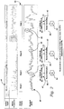
Figure 2 is a schematic of exemplary signals captured by each of a motion sensor and biosignal sensor of the adaptive noise quantification system, and -
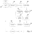
Figure 3 is a flow diagram of an exemplary method for adaptive noise quantification in dynamic biosignal analysis, in accordance with at least one embodiment. - The above described drawing figures illustrate aspects of the invention in at least one of its exemplary embodiments, which are further defined in detail in the following description. Features, elements, and aspects of the invention that are referenced by the same numerals in different figures represent the same, equivalent, or similar features, elements, or aspects, in accordance with one or more embodiments.
- Turning now to
Fig. 1 , there is shown a simplified schematic view of an exemplary adaptivenoise quantification system 20. Thesystem 20 provides, an at least onecomputing device 22 configured for receiving and processing select data obtained by an at least onesensor array 23 comprising each of an at least onebiosignal sensor 24 in communication with thecomputing device 22, and an at least onemotion sensor 26 in communication with thecomputing device 22. Additionally, in at least one embodiment, an at least onedata storage device 28 is in communication with thecomputing device 22 and configured for storing said data obtained by the at least onebiosignal sensor 24 andmotion sensor 26, along with certain other data as discussed further below. In at least one embodiment, thecomputing device 22 anddata storage device 28 are one and the same unit. - At the outset, it should be noted that communication between each of the at least one
computing device 22, at least onebiosignal sensor 24, at least onemotion sensor 26, and at least onedata storage device 28 may be achieved using any wired- or wireless-based communication protocol (or combination of protocols) now known or later developed. As such, the present invention should not be read as being limited to any one particular type of communication protocol, even though certain exemplary protocols may be mentioned herein for illustrative purposes. - In at least one embodiment, the
biosignal sensor 24 is positioned and configured for obtaining select data related to certain vitals of a user on which thebiosignal sensor 24 is positioned. For example, in one such embodiment, thebiosignal sensor 24 is an electrocardiogram ("ECG") sensor positioned and configured for obtaining data related to the user's heart activity (i.e., electrical activity of the user's heart). In still further embodiments, the at least onebiosignal sensor 24 may be any other type of sensor or combination of sensors - now known or later developed - capable of obtaining data related to desired vitals of the user and which might be susceptible to unwanted noise. Thus, while thepresent system 20 and associated methods are herein discussed in the context of ECG sensors and the user's heart activity for illustrative purposes, the scope of the present invention should not be read as being so limited. In at least one embodiment, themotion sensor 26 is positioned and configured for obtaining select data related to the user's motion level (i.e., at rest, low level of motion, medium level of motion, high level of motion, etc.), the purpose of which is explained further below. For example, in one such embodiment, themotion sensor 26 is a microelectromechanical system ("MEMS") tri-axial accelerometer. - With continued reference to
Fig. 1 , in at least one embodiment, the at least onebiosignal sensor 24 is positioned on a wearable device, such as garment or other accessory being worn by the user, such as described in at leastU.S. Patent Application Publication No. 2013/0338472 . In still further embodiments, the at least onebiosignal sensor 24 may be appropriately positioned in contact with (or proximal to) the user using any other means now known or later developed. Similarly, the at least onemotion sensor 26 may be appropriately positioned in contact with (or proximal to) the user using any means now known or later developed. As mentioned above, in at least one embodiment, both the at least onebiosignal sensor 24 and at least onemotion sensor 26 form thesensor array 23, which should be disposed in such a way that the motion data generated by the at least onemotion sensor 26 reflects the motion of the at least onebiosignal sensor 24. In at least one embodiment, thecomputing device 22 is also removably engagable with the user - either directly with the user's body or with a wearable device, such as garment or other accessory being worn by the user. In at least one such embodiment, themotion sensor 26 is positioned within thecomputing device 22. In at least one further such embodiment, thebiosignal sensor 24 is positioned within thecomputing device 22. In an alternate embodiment, thecomputing device 22 is positioned elsewhere - either still local to the user or remotely, or even divided, with some of the functional units implemented in acomputing device 22 local to the user and other units implemented in remote computer work stations. - In at least one embodiment, the
computing device 22 contains the hardware and software necessary to carry out the exemplary methods for performing adaptive noise quantification in dynamic biosignal analysis as described herein. In at least one embodiment, thecomputing device 22 provides abiosignal preprocessing module 30, abiosignal processing module 32, and abiosignal analysis module 34, each residing inmemory 38 on the computing device 22 (Fig. 1 ). As discussed further below, in at least one such embodiment, thebiosignal preprocessing module 30 is configured for receiving araw biosignal 40 captured by thebiosignal sensor 24, discarding any portion of thebiosignal 40 that is determined to be unsuitable for use, and preprocessing the suitable portions; thebiosignal processing module 32 is configured for receiving thepreprocessed biosignal 40 from thebiosignal preprocessing module 30, extracting from thebiosignal 40 the desired vitals and calculating the user's current motion level; and thebiosignal analysis module 34 is configured for receiving the vitals from thebiosignal processing module 32, calculating a noise descriptor set 42 for the vitals and, by using the noise descriptor set 42 and the user's current motion level, estimating anoise level 54 of thebiosignal 40. It should be noted that the term "memory" is intended to include any type of electronic storage medium (or combination of storage mediums) now known or later developed, such as local hard drives, solid state drives, RAM, flash memory, secure digital ("SD") cards, external storage devices, network or cloud storage devices, integrated circuits, etc. Furthermore, the various components of thecomputing device 22 may reside in memory on asingle computing device 22, or may separately reside on two ormore computing devices 22 in communication with one another. It should also be noted that while the exemplary methods for performing adaptive noise quantification in dynamic biosignal analysis are described herein as being carried out by the above-mentioned modules 30-34, in further embodiments, the below-described functionality may be carried out by more or less modules. Thus, thepresent system 20 should not be read as being limited to the particular modules 30-34, and their respective functions, described herein; but rather, should be read as generally covering the methods described herein. - In use, the
system 20 utilizes a method for estimating and quantifying the amount of noise - herein referred to as the noise level 54 - that is contaminating thebiosignal 40 captured by thebiosignal sensor 24, which takes advantage of the fact that the biosignal 40 contains some repetitive events, the vitals, which tend to be highly redundant or repetitive, while noise tends to be random. Noise is essentially random and is mainly provoked by slight and fast displacements of thebiosignal sensor 24 from its position relative to the user's body. These displacements are caused by movements of the user. Furthermore, similar motion levels - and similar movements - tend to have similar noise behavior, thereby allowing thesystem 20 to identify and distinguish different motion stages and, in turn, make better noise estimations. - In at least one embodiment, as illustrated in the exemplary schematic of
Fig. 2 and the flow diagram ofFig. 3 , amotion signal 44 is captured by themotion sensor 26 and transmitted to the computing device 22 (302), where it is analyzed to determine acurrent motion stage 46 of the user (304) - i.e., the wearer of at least themotion sensor 26 andbiosignal sensor 24. As mentioned above, in at least one embodiment, themotion sensor 26 is positioned and configured for obtaining select data related to the user's motion level (i.e., at rest, low level of motion, medium level of motion, high level of motion, etc.). Thus, in at least one embodiment, themotion stage 46 of the user is comprised of at least the user's motion level. In at least one embodiment, thecomputing device 22 extracts the necessary portions of themotion signal 44 and passes them to a classification function that determines themotion stage 46. In at least one such embodiment, where themotion sensor 26 is a MEMS tri-axial accelerometer, themotion sensor 26 measures accelerations in each of an orthogonal X, Y and Z direction and transmits the data, via the communication protocol, to thecomputing device 22. Using that data, thecomputing device 22 is able to calculate various parameters, including but not limited to a motion index ("MI") or a median absolute deviation ("MAD"). In a bit more detail, in at least one embodiment, the motion index is a 1-second window integration of the modulus of the X, Y, Z vector without gravitational influence (i.e., a high pass filtering of accelerometry components) using the following formula:

- Thus, in at least one embodiment, the classification function used to determine the
motion stage 46 is a threshold function dependent on previous parameters calculated in predefined intervals of time. - With continued reference to
Fig. 3 , in at least one embodiment, thebiosignal 40 is captured by thebiosignal sensor 24 and is also transmitted to the computing device 22 (306), where it is analyzed to determine and obtain the relevant vitals of the user. In at least one such embodiment, where thebiosignal sensor 24 is an ECG sensor or the like, thebiosignal sensor 24 senses and transmits raw ECG data, via the communication protocol, to thecomputing device 22. As mentioned above, in at least one embodiment, thebiosignal 40 is first received by thebiosignal preprocessing module 30, where any portion of the biosignal 40 determined to be unsuitable for use (i.e., saturated, etc.) is discarded (308). Additionally, any remaining portions of thebiosignal 40 are improved by filtering any baseline, power line or high frequency interferences (310). - The
biosignal processing module 32 then extracts from the preprocessedbiosignal 40 the desired vitals (312). In at least one embodiment, where thebiosignal sensor 24 is an ECG sensor or the like, the vitals are the heart beats that thebiosignal processing module 32 is configured to detect. - The
biosignal analysis module 34 then calculates a noise descriptor set 42 for each vital extracted by thebiosignal processing module 32. In at least one embodiment, where thebiosignal sensor 24 is an ECG sensor or the like, thebiosignal analysis module 34 obtains the noise descriptor set 42 for each heart beat, which will be used, together with thecorresponding motion stage 46, to estimate thenoise level 54 of the beat. In a bit more detail, in at least one embodiment, each noise descriptor set 42 is comprised of at least of one a morphological descriptor set ("MDS") 50, which describes the vitals, and an environmental descriptor set ("EDS") 52, which describes the environment context of the vitals. In at least one such embodiment, thebiosignal analysis module 34 calculates three parameters related to the morphological descriptor set 50 (314): a maximum second derivative ("Max2Der"), a derivative zero crosses ("DerivZX"), and a derivative asymmetry ("DerivAsym"). The Max2Der parameter is the maximum value of the absolute second derivative. As the second derivative describes the variation of the slope of thebiosignal 40, the maximum absolute value characterizes the concavity/convexity of thebiosignal 40; thus, high values indicate sharp peaks, such as spikes. The DerivZX parameter is the zero crosses count of the first derivative, modified by nullifying all values with an absolute value lower than ten percent (10%) of the maximum absolute value. This parameter is high when thebiosignal 40 has too many oscillations, such as when thebiosignal 40 is very noisy. The DerivAsym parameter is the ratio between the integral of the second half of the absolute derivative and the integral of the first half. In at least one embodiment, for each noise descriptor set 42, thebiosignal analysis module 34 also calculates the environmental descriptor set 52 (316), to be used by thecomputing device 22. For example, one such parameter of the environmental descriptor set 52 is related to adjacent heart beat segments in the biosignal 40 - when a given heart beat is adjacent to or near a relatively noisy segment in thebiosignal 40, such is typically indicative of a transition from a very noisy portion of the biosignal 40 to a relatively clean portion of thebiosignal 40. Another exemplary parameter of the environmental descriptor set 52 is related to the amplitude of a given heart beat - relatively lower amplitudes tend to be more suitable to having a low signal-to-noise ratio. Another exemplary parameter of the environmental descriptor set 52 is the similarity of the vital to the neighbor vitals, since noisy vitals are less similar to its neighbors and non-noisy vitals should be almost identical. Thus, in at least one embodiment, the noise descriptor set 42 is constructed by grouping both the morphological descriptor set 50 and environmental descriptor set 52 (i.e., { [MDS] , [EDS] }. - With continued reference to
Figs. 2 and3 , with themotion stage 46 of the user determined (304), thecomputing system 22 uses an appropriate noise estimator 56 (318) to determine thenoise level 54 of the biosignal 40 (320) using as input information the noise descriptor set 42 and themotion stage 46. In a bit more detail, in at least one such embodiment, thesystem 20 provides a plurality ofnoise estimators 56 with each being tailored and trained to model a different noise behavior for aparticular motion stage 46; so eachnoise estimator 56 is specialized in estimating thenoise level 54 of aparticular motion stage 46. Additionally, thenoise estimator 56 is preferably an at least one artificially intelligent system - such as a neural network - capable of estimating thenoise level 54 based on the morphological descriptor set 50 and environmental descriptor set 52 associated with a given noise descriptor set 42 of thebiosignal 40. The output of thenoise estimator 56 is anoise level 54 estimation ("NL") for thebiosignal 40, and a time-dependent noise level 54 function can be obtained for thebiosignal 40. This function has a constant value calculated for each discrete unit of the vitals (such as a heart beat, where thebiosignal sensor 24 is an ECG sensor or the like), so it is a time-dependent piecewise constant function. In at least one such embodiment, the function is defined as:
- In at least one embodiment, once the
noise level 54 for thebiosignal 40 has been obtained, this information is stored (322) so that it can be used in different ways by subsequent processing algorithms, such as heart rate calculation methods or arrhythmia detection for example. Thus, thesystem 20 is capable of performing noise quantification methods on biosignals by analyzing the motion data associated with the user and dynamically adapting the biosignal assessment based on that motion, independently of the physical activity which is being performed by the user. - In closing, regarding the exemplary embodiments of the present invention as shown and described herein, it will be appreciated that a system not forming part of the invention and associated methods for adaptive noise quantification in dynamic biosignal analysis is disclosed. Because the principles of the invention may be practiced in a number of configurations beyond those shown and described, it is to be understood that the present disclosure is not in any way limited by the exemplary embodiments, but is generally directed to a system and associated methods for adaptive noise quantification in dynamic biosignal analysis and is able to take numerous forms to do so without departing from the scope of the invention. It will also be appreciated by those skilled in the art that the present invention is not limited to the particular geometries and materials of construction disclosed, but may instead entail other functionally comparable structures or materials, now known or later developed, without departing from the scope of the invention. Furthermore, the various features of each of the above-described embodiments may be combined in any logical manner and are intended to be included within the scope of the present invention.
- Groupings of alternative embodiments, elements, or steps of the present invention are not to be construed as limitations. Each group member may be referred to and claimed individually or in any combination with other group members disclosed herein. It is anticipated that one or more members of a group may be included in, or deleted from, a group for reasons of convenience and/or patentability. When any such inclusion or deletion occurs, the specification is deemed to contain the group as modified thus fulfilling the written description of all Markush groups used in the appended claims.
- Unless otherwise indicated, all numbers expressing a characteristic, item, quantity, parameter, property, term, and so forth used in the present specification and claims are to be understood as being modified in all instances by the term "about." As used herein, the term "about" means that the characteristic, item, quantity, parameter, property, or term so qualified encompasses a range of plus or minus ten percent above and below the value of the stated characteristic, item, quantity, parameter, property, or term. Accordingly, unless indicated to the contrary, the numerical parameters set forth in the specification and attached claims are approximations that may vary. At the very least, and not as an attempt to limit the application of the doctrine of equivalents to the scope of the claims, each numerical indication should at least be construed in light of the number of reported significant digits and by applying ordinary rounding techniques. Notwithstanding that the numerical ranges and values setting forth the broad scope of the invention are approximations, the numerical ranges and values set forth in the specific examples are reported as precisely as possible. Any numerical range or value, however, inherently contains certain errors necessarily resulting from the standard deviation found in their respective testing measurements. Recitation of numerical ranges of values herein is merely intended to serve as a shorthand method of referring individually to each separate numerical value falling within the range. Unless otherwise indicated herein, each individual value of a numerical range is incorporated into the present specification as if it were individually recited herein.
- The terms "a," "an," "the" and similar referents used in the context of describing the present invention (especially in the context of the following claims) are to be construed to cover both the singular and the plural, unless otherwise indicated herein or clearly contradicted by context. All methods described herein can be performed in any suitable order unless otherwise indicated herein or otherwise clearly contradicted by context. The use of any and all examples, or exemplary language (e.g., "such as") provided herein is intended merely to better illuminate the present invention and does not pose a limitation on the scope of the invention otherwise claimed. No language in the present specification should be construed as indicating any non-claimed element essential to the practice of the invention.
- Specific embodiments disclosed herein may be further limited in the claims using consisting of or consisting essentially of language. When used in the claims, whether as filed or added per amendment, the transition term "consisting of" excludes any element, step, or ingredient not specified in the claims. The transition term "consisting essentially of" limits the scope of a claim to the specified materials or steps and those that do not materially affect the basic and novel characteristic(s). Embodiments of the present invention so claimed are inherently or expressly described and enabled herein.
- It should be understood that the logic code, programs, modules, processes, methods, and the order in which the respective elements of each method are performed are purely exemplary. Depending on the implementation, they may be performed in any order or in parallel, unless indicated otherwise in the present disclosure. Further, the logic code is not related, or limited to any particular programming language, and may comprise one or more modules that execute on one or more processors in a distributed, non-distributed, or multiprocessing environment.
- The methods as described above may be used in the fabrication of integrated circuit chips. The resulting integrated circuit chips can be distributed by the fabricator in raw wafer form (that is, as a single wafer that has multiple unpackaged chips), as a bare die, or in a packaged form. In the latter case, the chip is mounted in a single chip package (such as a plastic carrier, with leads that are affixed to a motherboard or other higher level carrier) or in a multi-chip package (such as a ceramic carrier that has either or both surface interconnections or buried interconnections). In any case, the chip is then integrated with other chips, discrete circuit elements, and/or other signal processing devices as part of either (a) an intermediate product, such as a motherboard, or (b) an end product. The end product can be any product that includes integrated circuit chips, ranging from toys and other low-end applications to advanced computer products having a display, a keyboard or other input device, and a central processor.
- While aspects of the invention have been described with reference to at least one exemplary embodiment, it is to be clearly understood by those skilled in the art that the invention is not limited thereto. Rather, the scope of the invention is to be interpreted only in conjunction with the appended claims and it is made clear, here, that the inventor(s) believe that the claimed subject matter is the invention.
Claims (8)
- A method for adaptive noise quantification in dynamic biosignal analysis of a user, the method comprising the steps of:transmitting to a computing device (22) an at least one motion signal (44) captured by an at least one motion sensor (26), the motion signal containing data related to a motion level of the user,wherein the motion sensor is a tri-axial accelerometer;transmitting to the computing device an at least one biosignal (40) captured by an at least one biosignal sensor (24), the biosignal containing data related to a select at least one vital of the user;determining by the computing device (22) a motion stage (46) of the user based on the at least one motion signal;wherein the motion stage is determined by a classification function being a threshold function using at least one of a motion index (MI) and a median absolute deviation (MAD) defined as:

 calculating, for each select at least one vital, a noise descriptor set comprising at least one of a morphological descriptor set (50) and an environmental descriptor set (52);generating a noise level estimation (54) of the select at least one vital based on at least one of the noise descriptor set and the motion stage of the user;calculating by the computing device (22) a noise level of the biosignal based on the noise level estimation of the select at least one vital; andstoring the noise level estimation at the computing device.
 - The method of claim 1, further comprising the step of positioning the at least one motion sensor on a wearable device worn by the user.
- The method of claim 2, wherein the step of positioning the at least one motion sensor further comprises the step of positioning an at least one tri-axial accelerometer on the wearable device worn by the user.
- The method of claim 1, further comprising the step of positioning the at least one biosignal sensor on a wearable device worn by the user.
- The method of claim 4, wherein the step of positioning the at least one biosignal sensor further comprises the step of positioning an at least one electrocardiogram sensor on the wearable device worn by the user.
- The method of any preceding claim, further comprising the step of grouping the at least one motion signal based on motion stages, thereby allowing the computing device to more accurately estimate, identify and separate out noise while performing dynamic biosignal analysis.
- The method of any preceding claim, further comprising the step of removing any baseline, power line, and high frequency interferences in the remaining portions of the biosignal.
- The method of any preceding claim, further comprising the step of selecting an appropriate noise estimator (56), based on the motion stage of the user, for generating the noise level estimation of the biosignal.
Priority Applications (1)
| Application Number | Priority Date | Filing Date | Title |
|---|---|---|---|
| PL16747455T PL3322327T3 (en) | 2015-07-14 | 2016-07-14 | Methods for adaptive noise quantification in dynamic biosignal analysis |
Applications Claiming Priority (3)
| Application Number | Priority Date | Filing Date | Title |
|---|---|---|---|
| US201562192504P | 2015-07-14 | 2015-07-14 | |
| ES201531026 | 2015-07-14 | ||
| PCT/EP2016/066802 WO2017009430A1 (en) | 2015-07-14 | 2016-07-14 | System and methods for adaptive noise quantification in dynamic biosignal analysis |
Publications (2)
| Publication Number | Publication Date |
|---|---|
| EP3322327A1 EP3322327A1 (en) | 2018-05-23 |
| EP3322327B1 true EP3322327B1 (en) | 2019-12-11 |
Family
ID=57757306
Family Applications (1)
| Application Number | Title | Priority Date | Filing Date |
|---|---|---|---|
| EP16747455.0A Active EP3322327B1 (en) | 2015-07-14 | 2016-07-14 | Methods for adaptive noise quantification in dynamic biosignal analysis |
Country Status (7)
| Country | Link |
|---|---|
| US (2) | US10588574B2 (en) |
| EP (1) | EP3322327B1 (en) |
| JP (1) | JP6843855B2 (en) |
| AU (1) | AU2016293066B2 (en) |
| CA (1) | CA2992368C (en) |
| PL (1) | PL3322327T3 (en) |
| WO (1) | WO2017009430A1 (en) |
Families Citing this family (8)
| Publication number | Priority date | Publication date | Assignee | Title |
|---|---|---|---|---|
| WO2019060298A1 (en) | 2017-09-19 | 2019-03-28 | Neuroenhancement Lab, LLC | Method and apparatus for neuroenhancement |
| US11717686B2 (en) | 2017-12-04 | 2023-08-08 | Neuroenhancement Lab, LLC | Method and apparatus for neuroenhancement to facilitate learning and performance |
| US12280219B2 (en) | 2017-12-31 | 2025-04-22 | NeuroLight, Inc. | Method and apparatus for neuroenhancement to enhance emotional response |
| US11318277B2 (en) | 2017-12-31 | 2022-05-03 | Neuroenhancement Lab, LLC | Method and apparatus for neuroenhancement to enhance emotional response |
| CN108379560B (en) * | 2018-02-02 | 2019-11-29 | 中山大学 | A kind of enteric solubility nano-particle of load insulin and its preparation method and application |
| US11364361B2 (en) | 2018-04-20 | 2022-06-21 | Neuroenhancement Lab, LLC | System and method for inducing sleep by transplanting mental states |
| CN113382683A (en) | 2018-09-14 | 2021-09-10 | 纽罗因恒思蒙特实验有限责任公司 | System and method for improving sleep |
| US11786694B2 (en) | 2019-05-24 | 2023-10-17 | NeuroLight, Inc. | Device, method, and app for facilitating sleep |
Family Cites Families (11)
| Publication number | Priority date | Publication date | Assignee | Title |
|---|---|---|---|---|
| AU2004290588A1 (en) * | 2003-11-18 | 2005-06-02 | Vivometrics, Inc. | Method and system for processing data from ambulatory physiological monitoring |
| KR100721803B1 (en) * | 2005-10-07 | 2007-05-25 | 삼성전자주식회사 | Noise removal method and noise removal system using behavior pattern change |
| US7725187B1 (en) * | 2006-11-06 | 2010-05-25 | Pacesetter, Inc. | Motion detection for sensors sensitive to motion induced noise |
| US8075499B2 (en) * | 2007-05-18 | 2011-12-13 | Vaidhi Nathan | Abnormal motion detector and monitor |
| US9451886B2 (en) * | 2009-04-22 | 2016-09-27 | Rodrigo E. Teixeira | Probabilistic parameter estimation using fused data apparatus and method of use thereof |
| US8909332B2 (en) * | 2010-01-26 | 2014-12-09 | Stmicroelectronics S.R.L. | Method and device for estimating morphological features of heart beats |
| WO2013075270A1 (en) * | 2011-11-25 | 2013-05-30 | Yang Chang-Ming | Object, method, and system for detecting heartbeat or whether or not electrodes are in proper contact |
| TWI498846B (en) * | 2012-07-06 | 2015-09-01 | Univ Nat Cheng Kung | Gait analysis method and gait analysis system |
| US10413251B2 (en) | 2012-10-07 | 2019-09-17 | Rhythm Diagnostic Systems, Inc. | Wearable cardiac monitor |
| JP2016512762A (en) * | 2013-03-15 | 2016-05-09 | ゾル メディカル コーポレーションZoll Medical Corporation | ECG noise reduction system for vehicle motion artifact removal |
| JP6469075B2 (en) * | 2013-03-29 | 2019-02-13 | コーニンクレッカ フィリップス エヌ ヴェKoninklijke Philips N.V. | Apparatus and method for ECG motion artifact removal |
-
2016
- 2016-07-13 US US15/209,506 patent/US10588574B2/en active Active
- 2016-07-14 PL PL16747455T patent/PL3322327T3/en unknown
- 2016-07-14 CA CA2992368A patent/CA2992368C/en active Active
- 2016-07-14 AU AU2016293066A patent/AU2016293066B2/en not_active Ceased
- 2016-07-14 JP JP2018521705A patent/JP6843855B2/en active Active
- 2016-07-14 WO PCT/EP2016/066802 patent/WO2017009430A1/en not_active Ceased
- 2016-07-14 EP EP16747455.0A patent/EP3322327B1/en active Active
-
2020
- 2020-02-04 US US16/781,402 patent/US11497450B2/en active Active
Non-Patent Citations (1)
| Title |
|---|
| None * |
Also Published As
| Publication number | Publication date |
|---|---|
| JP6843855B2 (en) | 2021-03-17 |
| WO2017009430A1 (en) | 2017-01-19 |
| AU2016293066A1 (en) | 2018-03-08 |
| CA2992368A1 (en) | 2017-01-19 |
| AU2016293066B2 (en) | 2020-09-10 |
| JP2018525187A (en) | 2018-09-06 |
| US11497450B2 (en) | 2022-11-15 |
| US20170014080A1 (en) | 2017-01-19 |
| CA2992368C (en) | 2022-01-18 |
| US20200170577A1 (en) | 2020-06-04 |
| PL3322327T3 (en) | 2020-05-18 |
| EP3322327A1 (en) | 2018-05-23 |
| US10588574B2 (en) | 2020-03-17 |
Similar Documents
| Publication | Publication Date | Title |
|---|---|---|
| US10588574B2 (en) | System and methods for adaptive noise quantification in dynamic biosignal analysis | |
| US9179862B2 (en) | Method and system for assessing locomotive bio-rhythms | |
| JP4921491B2 (en) | Body parameter detection | |
| JP6795980B2 (en) | A method of processing acceleration measurements to identify a step by a user and a corresponding computer program, and a device that processes acceleration measurements to identify a step by a user and a device comprising such a device. | |
| JP5674766B2 (en) | Sensing device for detecting wearing position | |
| US9042973B2 (en) | Apparatus and method for measuring physiological signal quality | |
| WO2017089921A1 (en) | Method to quantify photoplethysmogram (ppg) signal quality | |
| Tafreshi et al. | Automated analysis of ECG waveforms with atypical QRS complex morphologies | |
| JP6943287B2 (en) | Biometric information processing equipment, biometric information processing systems, biometric information processing methods, and programs | |
| US20160106332A1 (en) | Ecg waveform detecting apparatus and imaging apparatus | |
| CN114052693A (en) | Heart rate analysis method, device and equipment | |
| Bashar et al. | Extraction of heart rate from PPG signal: A machine learning approach using decision tree regression algorithm | |
| CN107847146B (en) | Method and system for automatic tagging of activity on ECG data | |
| JP6779518B2 (en) | Biosignal detection system, biosignal detection method | |
| KR102276614B1 (en) | Method and apparatus for measuring biosignal in a non-contact manner and clothes using the same | |
| John et al. | Multimodal fusion for robust respiratory rate estimation in wearable sensing | |
| US20170311899A1 (en) | Apparatus and method for identifying movement in a patient | |
| CN104274165B (en) | Determination device and determination method | |
| CN106419884B (en) | A kind of rate calculation method and system based on wavelet analysis | |
| EP3847961B1 (en) | Walking state determination program, walking state determination method, and information processing device | |
| Lee et al. | A wearable RFID system to monitor hand use for individuals with upper limb paresis | |
| EP3662824B1 (en) | Autonomous full spectrum biometric monitoring | |
| JP2015217060A (en) | Heart rate detection method and heart rate detection device | |
| ES2775531T3 (en) | Methods for adaptive noise quantification in dynamic biological signal analysis | |
| KR102849394B1 (en) | Method for determining optimal parameters for denoising based on features of bio-signal, and method and system for denoising using the same |
Legal Events
| Date | Code | Title | Description |
|---|---|---|---|
| STAA | Information on the status of an ep patent application or granted ep patent |
Free format text: STATUS: THE INTERNATIONAL PUBLICATION HAS BEEN MADE |
|
| PUAI | Public reference made under article 153(3) epc to a published international application that has entered the european phase |
Free format text: ORIGINAL CODE: 0009012 |
|
| STAA | Information on the status of an ep patent application or granted ep patent |
Free format text: STATUS: REQUEST FOR EXAMINATION WAS MADE |
|
| 17P | Request for examination filed |
Effective date: 20180213 |
|
| AK | Designated contracting states |
Kind code of ref document: A1 Designated state(s): AL AT BE BG CH CY CZ DE DK EE ES FI FR GB GR HR HU IE IS IT LI LT LU LV MC MK MT NL NO PL PT RO RS SE SI SK SM TR |
|
| AX | Request for extension of the european patent |
Extension state: BA ME |
|
| DAV | Request for validation of the european patent (deleted) | ||
| DAX | Request for extension of the european patent (deleted) | ||
| GRAP | Despatch of communication of intention to grant a patent |
Free format text: ORIGINAL CODE: EPIDOSNIGR1 |
|
| STAA | Information on the status of an ep patent application or granted ep patent |
Free format text: STATUS: GRANT OF PATENT IS INTENDED |
|
| INTG | Intention to grant announced |
Effective date: 20190318 |
|
| GRAS | Grant fee paid |
Free format text: ORIGINAL CODE: EPIDOSNIGR3 |
|
| GRAA | (expected) grant |
Free format text: ORIGINAL CODE: 0009210 |
|
| STAA | Information on the status of an ep patent application or granted ep patent |
Free format text: STATUS: THE PATENT HAS BEEN GRANTED |
|
| AK | Designated contracting states |
Kind code of ref document: B1 Designated state(s): AL AT BE BG CH CY CZ DE DK EE ES FI FR GB GR HR HU IE IS IT LI LT LU LV MC MK MT NL NO PL PT RO RS SE SI SK SM TR |
|
| REG | Reference to a national code |
Ref country code: GB Ref legal event code: FG4D |
|
| REG | Reference to a national code |
Ref country code: CH Ref legal event code: EP |
|
| REG | Reference to a national code |
Ref country code: AT Ref legal event code: REF Ref document number: 1211322 Country of ref document: AT Kind code of ref document: T Effective date: 20191215 |
|
| REG | Reference to a national code |
Ref country code: DE Ref legal event code: R096 Ref document number: 602016026026 Country of ref document: DE |
|
| REG | Reference to a national code |
Ref country code: IE Ref legal event code: FG4D |
|
| REG | Reference to a national code |
Ref country code: PT Ref legal event code: SC4A Ref document number: 3322327 Country of ref document: PT Date of ref document: 20200306 Kind code of ref document: T Free format text: AVAILABILITY OF NATIONAL TRANSLATION Effective date: 20200302 |
|
| RAP2 | Party data changed (patent owner data changed or rights of a patent transferred) |
Owner name: SMART SOLUTIONS TECHNOLOGIES, S.L. |
|
| REG | Reference to a national code |
Ref country code: NL Ref legal event code: MP Effective date: 20191211 |
|
| REG | Reference to a national code |
Ref country code: LT Ref legal event code: MG4D |
|
| PG25 | Lapsed in a contracting state [announced via postgrant information from national office to epo] |
Ref country code: LT Free format text: LAPSE BECAUSE OF FAILURE TO SUBMIT A TRANSLATION OF THE DESCRIPTION OR TO PAY THE FEE WITHIN THE PRESCRIBED TIME-LIMIT Effective date: 20191211 Ref country code: NO Free format text: LAPSE BECAUSE OF FAILURE TO SUBMIT A TRANSLATION OF THE DESCRIPTION OR TO PAY THE FEE WITHIN THE PRESCRIBED TIME-LIMIT Effective date: 20200311 Ref country code: BG Free format text: LAPSE BECAUSE OF FAILURE TO SUBMIT A TRANSLATION OF THE DESCRIPTION OR TO PAY THE FEE WITHIN THE PRESCRIBED TIME-LIMIT Effective date: 20200311 Ref country code: GR Free format text: LAPSE BECAUSE OF FAILURE TO SUBMIT A TRANSLATION OF THE DESCRIPTION OR TO PAY THE FEE WITHIN THE PRESCRIBED TIME-LIMIT Effective date: 20200312 Ref country code: FI Free format text: LAPSE BECAUSE OF FAILURE TO SUBMIT A TRANSLATION OF THE DESCRIPTION OR TO PAY THE FEE WITHIN THE PRESCRIBED TIME-LIMIT Effective date: 20191211 Ref country code: LV Free format text: LAPSE BECAUSE OF FAILURE TO SUBMIT A TRANSLATION OF THE DESCRIPTION OR TO PAY THE FEE WITHIN THE PRESCRIBED TIME-LIMIT Effective date: 20191211 Ref country code: SE Free format text: LAPSE BECAUSE OF FAILURE TO SUBMIT A TRANSLATION OF THE DESCRIPTION OR TO PAY THE FEE WITHIN THE PRESCRIBED TIME-LIMIT Effective date: 20191211 |
|
| PG25 | Lapsed in a contracting state [announced via postgrant information from national office to epo] |
Ref country code: RS Free format text: LAPSE BECAUSE OF FAILURE TO SUBMIT A TRANSLATION OF THE DESCRIPTION OR TO PAY THE FEE WITHIN THE PRESCRIBED TIME-LIMIT Effective date: 20191211 Ref country code: HR Free format text: LAPSE BECAUSE OF FAILURE TO SUBMIT A TRANSLATION OF THE DESCRIPTION OR TO PAY THE FEE WITHIN THE PRESCRIBED TIME-LIMIT Effective date: 20191211 |
|
| PG25 | Lapsed in a contracting state [announced via postgrant information from national office to epo] |
Ref country code: AL Free format text: LAPSE BECAUSE OF FAILURE TO SUBMIT A TRANSLATION OF THE DESCRIPTION OR TO PAY THE FEE WITHIN THE PRESCRIBED TIME-LIMIT Effective date: 20191211 |
|
| REG | Reference to a national code |
Ref country code: ES Ref legal event code: FG2A Ref document number: 2775531 Country of ref document: ES Kind code of ref document: T3 Effective date: 20200727 |
|
| PG25 | Lapsed in a contracting state [announced via postgrant information from national office to epo] |
Ref country code: CZ Free format text: LAPSE BECAUSE OF FAILURE TO SUBMIT A TRANSLATION OF THE DESCRIPTION OR TO PAY THE FEE WITHIN THE PRESCRIBED TIME-LIMIT Effective date: 20191211 Ref country code: RO Free format text: LAPSE BECAUSE OF FAILURE TO SUBMIT A TRANSLATION OF THE DESCRIPTION OR TO PAY THE FEE WITHIN THE PRESCRIBED TIME-LIMIT Effective date: 20191211 Ref country code: NL Free format text: LAPSE BECAUSE OF FAILURE TO SUBMIT A TRANSLATION OF THE DESCRIPTION OR TO PAY THE FEE WITHIN THE PRESCRIBED TIME-LIMIT Effective date: 20191211 Ref country code: EE Free format text: LAPSE BECAUSE OF FAILURE TO SUBMIT A TRANSLATION OF THE DESCRIPTION OR TO PAY THE FEE WITHIN THE PRESCRIBED TIME-LIMIT Effective date: 20191211 |
|
| PG25 | Lapsed in a contracting state [announced via postgrant information from national office to epo] |
Ref country code: SK Free format text: LAPSE BECAUSE OF FAILURE TO SUBMIT A TRANSLATION OF THE DESCRIPTION OR TO PAY THE FEE WITHIN THE PRESCRIBED TIME-LIMIT Effective date: 20191211 Ref country code: IS Free format text: LAPSE BECAUSE OF FAILURE TO SUBMIT A TRANSLATION OF THE DESCRIPTION OR TO PAY THE FEE WITHIN THE PRESCRIBED TIME-LIMIT Effective date: 20200411 Ref country code: SM Free format text: LAPSE BECAUSE OF FAILURE TO SUBMIT A TRANSLATION OF THE DESCRIPTION OR TO PAY THE FEE WITHIN THE PRESCRIBED TIME-LIMIT Effective date: 20191211 |
|
| REG | Reference to a national code |
Ref country code: DE Ref legal event code: R097 Ref document number: 602016026026 Country of ref document: DE |
|
| REG | Reference to a national code |
Ref country code: AT Ref legal event code: MK05 Ref document number: 1211322 Country of ref document: AT Kind code of ref document: T Effective date: 20191211 |
|
| PLBE | No opposition filed within time limit |
Free format text: ORIGINAL CODE: 0009261 |
|
| STAA | Information on the status of an ep patent application or granted ep patent |
Free format text: STATUS: NO OPPOSITION FILED WITHIN TIME LIMIT |
|
| PG25 | Lapsed in a contracting state [announced via postgrant information from national office to epo] |
Ref country code: DK Free format text: LAPSE BECAUSE OF FAILURE TO SUBMIT A TRANSLATION OF THE DESCRIPTION OR TO PAY THE FEE WITHIN THE PRESCRIBED TIME-LIMIT Effective date: 20191211 |
|
| 26N | No opposition filed |
Effective date: 20200914 |
|
| PG25 | Lapsed in a contracting state [announced via postgrant information from national office to epo] |
Ref country code: SI Free format text: LAPSE BECAUSE OF FAILURE TO SUBMIT A TRANSLATION OF THE DESCRIPTION OR TO PAY THE FEE WITHIN THE PRESCRIBED TIME-LIMIT Effective date: 20191211 Ref country code: AT Free format text: LAPSE BECAUSE OF FAILURE TO SUBMIT A TRANSLATION OF THE DESCRIPTION OR TO PAY THE FEE WITHIN THE PRESCRIBED TIME-LIMIT Effective date: 20191211 |
|
| PG25 | Lapsed in a contracting state [announced via postgrant information from national office to epo] |
Ref country code: MC Free format text: LAPSE BECAUSE OF FAILURE TO SUBMIT A TRANSLATION OF THE DESCRIPTION OR TO PAY THE FEE WITHIN THE PRESCRIBED TIME-LIMIT Effective date: 20191211 |
|
| REG | Reference to a national code |
Ref country code: CH Ref legal event code: PL |
|
| REG | Reference to a national code |
Ref country code: BE Ref legal event code: MM Effective date: 20200731 |
|
| PG25 | Lapsed in a contracting state [announced via postgrant information from national office to epo] |
Ref country code: LU Free format text: LAPSE BECAUSE OF NON-PAYMENT OF DUE FEES Effective date: 20200714 Ref country code: LI Free format text: LAPSE BECAUSE OF NON-PAYMENT OF DUE FEES Effective date: 20200731 Ref country code: CH Free format text: LAPSE BECAUSE OF NON-PAYMENT OF DUE FEES Effective date: 20200731 |
|
| PG25 | Lapsed in a contracting state [announced via postgrant information from national office to epo] |
Ref country code: BE Free format text: LAPSE BECAUSE OF NON-PAYMENT OF DUE FEES Effective date: 20200731 |
|
| PG25 | Lapsed in a contracting state [announced via postgrant information from national office to epo] |
Ref country code: IE Free format text: LAPSE BECAUSE OF NON-PAYMENT OF DUE FEES Effective date: 20200714 |
|
| PGFP | Annual fee paid to national office [announced via postgrant information from national office to epo] |
Ref country code: PT Payment date: 20210707 Year of fee payment: 6 |
|
| PG25 | Lapsed in a contracting state [announced via postgrant information from national office to epo] |
Ref country code: TR Free format text: LAPSE BECAUSE OF FAILURE TO SUBMIT A TRANSLATION OF THE DESCRIPTION OR TO PAY THE FEE WITHIN THE PRESCRIBED TIME-LIMIT Effective date: 20191211 Ref country code: MT Free format text: LAPSE BECAUSE OF FAILURE TO SUBMIT A TRANSLATION OF THE DESCRIPTION OR TO PAY THE FEE WITHIN THE PRESCRIBED TIME-LIMIT Effective date: 20191211 Ref country code: CY Free format text: LAPSE BECAUSE OF FAILURE TO SUBMIT A TRANSLATION OF THE DESCRIPTION OR TO PAY THE FEE WITHIN THE PRESCRIBED TIME-LIMIT Effective date: 20191211 |
|
| PG25 | Lapsed in a contracting state [announced via postgrant information from national office to epo] |
Ref country code: MK Free format text: LAPSE BECAUSE OF FAILURE TO SUBMIT A TRANSLATION OF THE DESCRIPTION OR TO PAY THE FEE WITHIN THE PRESCRIBED TIME-LIMIT Effective date: 20191211 |
|
| PG25 | Lapsed in a contracting state [announced via postgrant information from national office to epo] |
Ref country code: PT Free format text: LAPSE BECAUSE OF NON-PAYMENT OF DUE FEES Effective date: 20230116 |
|
| PGFP | Annual fee paid to national office [announced via postgrant information from national office to epo] |
Ref country code: ES Payment date: 20250826 Year of fee payment: 10 |
|
| PGFP | Annual fee paid to national office [announced via postgrant information from national office to epo] |
Ref country code: DE Payment date: 20250722 Year of fee payment: 10 |
|
| PGFP | Annual fee paid to national office [announced via postgrant information from national office to epo] |
Ref country code: IT Payment date: 20250724 Year of fee payment: 10 Ref country code: PL Payment date: 20250711 Year of fee payment: 10 |
|
| PGFP | Annual fee paid to national office [announced via postgrant information from national office to epo] |
Ref country code: GB Payment date: 20250722 Year of fee payment: 10 |
|
| PGFP | Annual fee paid to national office [announced via postgrant information from national office to epo] |
Ref country code: FR Payment date: 20250725 Year of fee payment: 10 |