EP3322260B1 - Light and display content integration method - Google Patents
Light and display content integration method Download PDFInfo
- Publication number
- EP3322260B1 EP3322260B1 EP16820742.1A EP16820742A EP3322260B1 EP 3322260 B1 EP3322260 B1 EP 3322260B1 EP 16820742 A EP16820742 A EP 16820742A EP 3322260 B1 EP3322260 B1 EP 3322260B1
- Authority
- EP
- European Patent Office
- Prior art keywords
- signal
- light
- display content
- display
- area
- Prior art date
- Legal status (The legal status is an assumption and is not a legal conclusion. Google has not performed a legal analysis and makes no representation as to the accuracy of the status listed.)
- Active
Links
Images


Classifications
-
- H—ELECTRICITY
- H05—ELECTRIC TECHNIQUES NOT OTHERWISE PROVIDED FOR
- H05B—ELECTRIC HEATING; ELECTRIC LIGHT SOURCES NOT OTHERWISE PROVIDED FOR; CIRCUIT ARRANGEMENTS FOR ELECTRIC LIGHT SOURCES, IN GENERAL
- H05B47/00—Circuit arrangements for operating light sources in general, i.e. where the type of light source is not relevant
-
- G—PHYSICS
- G09—EDUCATION; CRYPTOGRAPHY; DISPLAY; ADVERTISING; SEALS
- G09G—ARRANGEMENTS OR CIRCUITS FOR CONTROL OF INDICATING DEVICES USING STATIC MEANS TO PRESENT VARIABLE INFORMATION
- G09G3/00—Control arrangements or circuits, of interest only in connection with visual indicators other than cathode-ray tubes
- G09G3/20—Control arrangements or circuits, of interest only in connection with visual indicators other than cathode-ray tubes for presentation of an assembly of a number of characters, e.g. a page, by composing the assembly by combination of individual elements arranged in a matrix no fixed position being assigned to or needed to be assigned to the individual characters or partial characters
- G09G3/2007—Display of intermediate tones
-
- G—PHYSICS
- G09—EDUCATION; CRYPTOGRAPHY; DISPLAY; ADVERTISING; SEALS
- G09G—ARRANGEMENTS OR CIRCUITS FOR CONTROL OF INDICATING DEVICES USING STATIC MEANS TO PRESENT VARIABLE INFORMATION
- G09G3/00—Control arrangements or circuits, of interest only in connection with visual indicators other than cathode-ray tubes
- G09G3/04—Control arrangements or circuits, of interest only in connection with visual indicators other than cathode-ray tubes for presentation of a single character by selection from a plurality of characters, or by composing the character by combination of individual elements, e.g. segments using a combination of such display devices for composing words, rows or the like, in a frame with fixed character positions
- G09G3/06—Control arrangements or circuits, of interest only in connection with visual indicators other than cathode-ray tubes for presentation of a single character by selection from a plurality of characters, or by composing the character by combination of individual elements, e.g. segments using a combination of such display devices for composing words, rows or the like, in a frame with fixed character positions using controlled light sources
-
- Y—GENERAL TAGGING OF NEW TECHNOLOGICAL DEVELOPMENTS; GENERAL TAGGING OF CROSS-SECTIONAL TECHNOLOGIES SPANNING OVER SEVERAL SECTIONS OF THE IPC; TECHNICAL SUBJECTS COVERED BY FORMER USPC CROSS-REFERENCE ART COLLECTIONS [XRACs] AND DIGESTS
- Y02—TECHNOLOGIES OR APPLICATIONS FOR MITIGATION OR ADAPTATION AGAINST CLIMATE CHANGE
- Y02B—CLIMATE CHANGE MITIGATION TECHNOLOGIES RELATED TO BUILDINGS, e.g. HOUSING, HOUSE APPLIANCES OR RELATED END-USER APPLICATIONS
- Y02B20/00—Energy efficient lighting technologies, e.g. halogen lamps or gas discharge lamps
- Y02B20/40—Control techniques providing energy savings, e.g. smart controller or presence detection
Definitions
- the invention relates to the field of display, and more particularly, to light and display content integration method.
- EP 2 854 392 A1 discloses lighting systems and methods for enhancing the functionality of display units.
- the present invention provides a method for integration of light and display content, which can intelligently adjust lighting tone according to the display content.
- the above technical schemes have the advantages that:
- the present technical schemes control an output of a corresponding light signal and display content signal according to different input signals by analyzing a type of the input signal, so as to achieve an effect where display content and lighting tone can be intelligently adjusted, allowing the light signal and the display signal to be well integrated, thus expanding the scope of the application.
- the term "plurality” means a number greater than one.
- a method for integration of light and display content applicable to a display device.
- the display device is an integrated screen, comprising a display area and a light area.
- the light area is illuminated by an LED array located behind the display area and around a periphery of the display area.
- the LED array comprises a plurality of light set units, and the display area is divided into a plurality of video regions according to the number of the light set unit, each video region corresponding to one light set unit:
- the method for integration of light and display content comprises the following steps of:
- the display area is located inside a screen.
- the light area is a screen portion excluding the display area, which is illuminated by an LED array disposed in an area behind the screen and surrounding the display area.
- the LED array comprises a plurality of light set units.
- the display area is virtually divided into a plurality of video regions according to the number of the LED array, each video region corresponding to one light set unit. If the input signal comprises the display content signal and the light signal, the input display content signal and the light signal can be served as input signals that have integrated and adapted the LED array and the display area.
- the present technical schemes control an output of a corresponding light signal and display content signal according to different input signals by analyzing a type of the input signal, so as to achieve an effect where display content and lighting tone can be intelligently adjusted, allowing the light signal and the display content signal to be well integrated, thus expanding the scope of the application.
- both the resolution and the definition of the display area are higher than those of the light area illuminated by the LED array.
- the lighting effect of the LED array is consistent with the display content in the display area by driving the LED array according to the display content signal, so as to create a broad view of vision and make the display content more vivid.
- the display device further comprises a boundary area located around the periphery of the display area and bordering the light area.
- the display content can be divided into a dynamic video and a static image
- the light signal can be divided into a static light signal and a dynamic light signal.
- the boundary area located at an outer edge of the display area will integrate the display content with the lighting effect emitted by the LED array, so that the edge of the display content will be free from the interference of the light emitted by the LED array, avoiding ambiguous visual effect.
- Step S4 when the display content signal is a dynamic video, extracting the color space of consecutive video frames of each of the video regions in the display content signal, and a average value of the tone data in the color space of the consecutive video frames of the video region is calculated at a first predetermined interval, then generating the light signal of the light set units corresponding to the video region based on the tone data.
- the first predetermined interval can range from 0.5 seconds to 2 seconds.
- the main color tone of the video area is calculated first by making the light set units corresponding to the video regions, to generate light information of corresponding light set units, and all the light information is combined into the light signal, then a video frame of the dynamic video (display content signal) is sent to the display area for display, and the light signal is sent to the LED array for display.
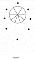
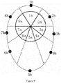
- the number of the video region is equal to that of the light set units, in the meantime, in order to achieve an optimal display effect as a whole, the video region can be uniformly zoned according to the arrangement of the light set units, as shown in Figures 2 and 3 , and in Figure 4 , the video region is non-uniformly zoned according to the arrangement of the light set units, wherein the light signal of the light set unit is corresponding to the main tone value of the video frame of the closest video region.
- Step S4 when the display content signal is a static image, extracting the tone data of each video region of the display content signal, and generating the corresponding light signal based on the tone data, wherein the light signal is a static light signal.
- a full image of the static image can be calculated to obtain a single main tone value, so as to control all the light set units to operate by adopting the light signal corresponding to the main tone value.
- Step S4 when the display content signal is a static image, RGB values of the tone data for each static image are respectively divided into X intervals to form a color space data of X 3 intervals, calculating a color histogram of the display content signal, extracting Y intervals with the highest numerical values in the color histogram, and obtaining median values of the RGB values in the Y intervals, and combining median values of the Y RGB values to form a main tone color space, and arranging the Y median values into a continuous sequence to generate the light signal based on the distribution of the Y median values in the color space, each of the RGB values in the Y median values having a duration of a preset interval, and the light signal being the dynamic light signal; wherein, X and Y are positive integers, 2 ⁇ X ⁇ 50, 0 ⁇ Y ⁇ X 3
- the preset interval can range from 0.5 seconds to 2 seconds.
- the light set units can also be operated by using the dynamic light signal.
- RGB abbreviation for red, green, and blue, that is, red, green and blue
- the entire color space becomes 1000 intervals of 10 ⁇ 10 ⁇ 10.
- the color histogram of the entire image is calculated, and 100 intervals of the highest value are taken out, to form a main tone color space with the median values of the RGB values of the 100 intervals.
- each light set unit Based on the distribution of 100 RGB median values in the color space, starting arrangement from one direction to form a continuous sequence, and the arranged sequence is generated into corresponding light signals, and the duration of each light set unit can be adjusted according to the actual effect, wherein the duration is associated with a density of the light set unit around the display area and a relative configuration of the video region.
- Step S5 when the light signal is a dynamic light signal, dynamic information of a change of the light signal is obtained, and light change frequency of each light set unit is obtained according to the dynamic information, and generating the display content signal corresponding to the change frequency, so as to display a dynamic oscillogram corresponding to the change frequency.
- the video region can present an image of dynamic correlation information associated with the change of the dynamic light signal.
- the frequency of lighting change can be calculated to show the frequency change characteristics of each light set unit in a three-dimensional perspective. Since each light set unit has the same or similar frequency, and its frequency change rate is very slow, or has a stable frequency value, sinusoidal waveform can be used to represent the frequency characteristics, and color of the waveform per se can be in consistent with the color of the light set unit.
- Step S5 when the light signal is a static light signal, the tone data of the light signal is obtained, the tone data comprise a tone value, and each light set unit corresponds to the tone value, and generating a single signal of each video region corresponding to the light set unit, and combining all the single signals to generate the display content signal.
- the video region when the input light signal is a static light signal, the video region can display a single signal with the same color and brightness value.
- the tone data is represented in a RGB format.
- the tone data represented in the RGB format can comprises lighting intensity information without being specified separately.
- Gaussian blur processing can be performed to the boundary area, such that blurriness of the boundary area is increasing from the inside to the outside, to eliminate an obvious boundary between an entire video region and the LED array.
- the input signal is the dynamic video
- a display device of a target comprises the display area and the light area illuminated by the LED array (as shown in Figures 4 and 5 ).
- the display device is displayed in a partitioned mode and a corresponding format as shown in the Figure 5 , that is, the light set units (1b-8b) correspond to the video regions (1a-8a) with corresponding reference numerals.
- a boundary area equivalent to 5% of the width of the size of the display content can be added outside the display content, and the boundary area can be filled with Tiffany blue. Adjusting the size of the video frame in which the boundary area has been added to reach a target size, then the width of the boundary area is divided into five even parts, and Gaussian Blur processing from gradient 1-2 is performed to the boundary area with parameters, the blurriness is increasing outwardly, and the outermost part is well integrated with the light area, to achieve a natural-transition effect in the boundary area.
- the light signal and the display content signal having been processed by an integration method, are combined into a final overall display content signal. Since the light signal changes once per second, while a frame rate of a video is much larger than 1, correspondence is done according to the time during integration, and the light signal is inserted into the display content signal, and a specific mark is added to describe the signal characteristics to form an integration signal, and the integration signal is transmitted to the display content signal for display.
- the input signal is a static single light signal
- a target display device comprises the display area and the light area illuminated by the LED array (as shown in Figure 3 ).
- the display area can be displayed in a manner that the same tone is displayed to enhance the lighting effect.
- the specific process of obtaining the display content signal is as follows: the RGB value of the light signal is obtained first, and then the value is set as the pixel value of the overall display area. It is also possible to add a random deviation of 1/50 of the overall amplitude value to the RGB values respectively and then generate a display content signal in a video frame format with a frame rate of 30 to mimic the influence of various factors on the display device in a natural state.
- the light signal and the display content signal having been processed by an integration method, are combined into a final overall display signal. Since the light signal refreshes once per second, while the frame rate of a video is 30, correspondence is done according to the time during integration, and the light signal is inserted into the display content signal, and a specific mark is added to describe the signal characteristics to form an integration signal, and the integration signal is transmitted to the display content signal for display.
Landscapes
- Engineering & Computer Science (AREA)
- Physics & Mathematics (AREA)
- Computer Hardware Design (AREA)
- General Physics & Mathematics (AREA)
- Theoretical Computer Science (AREA)
- Control Of Indicators Other Than Cathode Ray Tubes (AREA)
- Transforming Electric Information Into Light Information (AREA)
- Controls And Circuits For Display Device (AREA)
- Control Of El Displays (AREA)
Description
- The invention relates to the field of display, and more particularly, to light and display content integration method.
- With regard to a technology, traditional light, together with a display, is utilized for display, wherein it is achieved in a way that light cooperates with the change of the tone and the brightness of display content. However, since limiting light of the conventional technology plays a smaller role in assisting the display, the light cannot be well integrated with the display content. Moreover, the traditional light can only cooperate with the display content in a preset specific display mode for display, having limitations and poor practicability.
- In the prior art,
EP 2 854 392 A1 - Given that the foregoing problems exist in the integration of the existing light and display content, the present invention provides a method for integration of light and display content, which can intelligently adjust lighting tone according to the display content.
- Specific technical schemes are as disclosed in claim 1 with further schemes disclosed in the dependent claims.
- The above technical schemes have the advantages that:
The present technical schemes control an output of a corresponding light signal and display content signal according to different input signals by analyzing a type of the input signal, so as to achieve an effect where display content and lighting tone can be intelligently adjusted, allowing the light signal and the display signal to be well integrated, thus expanding the scope of the application. - The accompanying drawings, together with the specification, illustrate exemplary embodiments of the present disclosure, and, together with the description, serve to explain the principles of the present invention.
-
Figure 1 is a flowchart of an embodiment of a method for integration of light and display content of the present invention; -
Figure 2 is a schematic diagram of an embodiment in which a video region and light set units being uniformly zoned and arranged; -
Figure 3 is a schematic diagram of another embodiment in which a video region and light set units are uniformly zoned and arranged; -
Figure 4 is a schematic diagram of an embodiment in which a video area and light set units are non-uniformly zoned and arranged; -
Figure 5 is a schematic diagram of the zones ofFigure 4 . - The present invention will now be described more fully hereinafter with reference to the accompanying drawings, in which exemplary embodiments of the invention are shown. This invention may, however, be embodied in many different forms and should not be construed as limited to the embodiments set forth herein. Rather, these embodiments are provided so that this disclosure will be thorough and complete, and will fully convey the scope of the invention to those skilled in the art. Like reference numerals refer to like elements throughout.
- The terminology used herein is for the purpose of describing particular embodiments only and is not intended to be limiting of the invention. As used herein, the singular forms "a", "an" and "the" are intended to include the plural forms as well, unless the context clearly indicates otherwise. It will be further understood that the terms "comprises" and/or "comprising," or "includes" and/or "including" or "has" and/or "having" when used herein, specify the presence of stated features, regions, integers, steps, operations, elements, and/or components, but do not preclude the presence or addition of one or more other features, regions, integers, steps, operations, elements, components, and/or groups thereof.
- Unless otherwise defined, all terms (including technical and scientific terms) used herein have the same meaning as commonly understood by one of ordinary skill in the art to which this invention belongs. It will be further understood that terms, such as those defined in commonly used dictionaries, should be interpreted as having a meaning that is consistent with their meaning in the context of the relevant art and the present disclosure, and will not be interpreted in an idealized or overly formal sense unless expressly so defined herein.
- As used herein, "around", "about" or "approximately" shall generally mean within 20 percent, preferably within 10 percent, and more preferably within 5 percent of a given value or range. Numerical quantities given herein are approximate, meaning that the term "around", "about" or "approximately" can be inferred if not expressly stated.
- As used herein, the term "plurality" means a number greater than one.
- Hereinafter, certain exemplary embodiments according to the present disclosure will be described with reference to the accompanying drawings.
- As shown in
Figure 1 , a method for integration of light and display content, applicable to a display device. The display device is an integrated screen, comprising a display area and a light area. The light area is illuminated by an LED array located behind the display area and around a periphery of the display area. Wherein, the LED array comprises a plurality of light set units, and the display area is divided into a plurality of video regions according to the number of the light set unit, each video region corresponding to one light set unit:
wherein, the method for integration of light and display content comprises the following steps of: - S1. obtaining an input signal, then executing Step S2;
- S2. analyzing a type of the input signal; whereby the type of input signal is one of
- both a display content signal and a light signal,
- a display content signal only,
- a light signal only;
if the input signal is the display content signal, executing Step S4;
if the input signal is the light signal, executing Step S5; - S3. outputting the input signal as an integration signal to the display device and exit;
- S4. extracting, from said display content signal, a color space data of a video frame of each video region in the display area, obtaining by calculation, for each video region respective tone data corresponding to the respective color space data, and generating a light signal for the light set units based on the respective tone data, then executing Step S6;
- S5. obtaining the tone data of the light signal, and generating a display content signal having the same color as the tone data based on the tone data, then executing Step S6;
- S6. inserting the light signal into the display content signal according to corresponding time and a corresponding relationship between the light set units and the video regions, and adding a mark to the display content signal to describe a feature of the display content signal, so as to form the integration signal, and sending the integration signal to the display device.
- In this embodiment, the display area is located inside a screen. The light area is a screen portion excluding the display area, which is illuminated by an LED array disposed in an area behind the screen and surrounding the display area. Wherein, the LED array comprises a plurality of light set units. The display area is virtually divided into a plurality of video regions according to the number of the LED array, each video region corresponding to one light set unit. If the input signal comprises the display content signal and the light signal, the input display content signal and the light signal can be served as input signals that have integrated and adapted the LED array and the display area.
- The present technical schemes control an output of a corresponding light signal and display content signal according to different input signals by analyzing a type of the input signal, so as to achieve an effect where display content and lighting tone can be intelligently adjusted, allowing the light signal and the display content signal to be well integrated, thus expanding the scope of the application.
- Specifically, in the present invention, both the resolution and the definition of the display area are higher than those of the light area illuminated by the LED array. The lighting effect of the LED array is consistent with the display content in the display area by driving the LED array according to the display content signal, so as to create a broad view of vision and make the display content more vivid.
- In a preferred embodiment, wherein the display device further comprises a boundary area located around the periphery of the display area and bordering the light area.
- In this embodiment, the display content can be divided into a dynamic video and a static image, and the light signal can be divided into a static light signal and a dynamic light signal. When the display content is the dynamic video or the static image, the boundary area located at an outer edge of the display area will integrate the display content with the lighting effect emitted by the LED array, so that the edge of the display content will be free from the interference of the light emitted by the LED array, avoiding ambiguous visual effect.
- In a preferred embodiment, wherein in Step S4, when the display content signal is a dynamic video, extracting the color space of consecutive video frames of each of the video regions in the display content signal, and a average value of the tone data in the color space of the consecutive video frames of the video region is calculated at a first predetermined interval, then generating the light signal of the light set units corresponding to the video region based on the tone data.
- Specifically, since the frame rate of the dynamic video is generally higher, when calculating the main tone of the video area, an average value of the main tones of the corresponding areas of the plurality of consecutive video frames may be calculated to improve the visual effect of the lighting. The first predetermined interval can range from 0.5 seconds to 2 seconds.
- In this embodiment, when the display content signal is a dynamic video, the main color tone of the video area is calculated first by making the light set units corresponding to the video regions, to generate light information of corresponding light set units, and all the light information is combined into the light signal, then a video frame of the dynamic video (display content signal) is sent to the display area for display, and the light signal is sent to the LED array for display. In this embodiment, the number of the video region is equal to that of the light set units, in the meantime, in order to achieve an optimal display effect as a whole, the video region can be uniformly zoned according to the arrangement of the light set units, as shown in
Figures 2 and 3 , and inFigure 4 , the video region is non-uniformly zoned according to the arrangement of the light set units, wherein the light signal of the light set unit is corresponding to the main tone value of the video frame of the closest video region. - In a preferred embodiment, wherein in Step S4, when the display content signal is a static image, extracting the tone data of each video region of the display content signal, and generating the corresponding light signal based on the tone data, wherein the light signal is a static light signal.
- In this embodiment, when the display content signal is a static image, a full image of the static image can be calculated to obtain a single main tone value, so as to control all the light set units to operate by adopting the light signal corresponding to the main tone value.
- In Step S4, when the display content signal is a static image, RGB values of the tone data for each static image are respectively divided into X intervals to form a color space data of X3 intervals, calculating a color histogram of the display content signal, extracting Y intervals with the highest numerical values in the color histogram, and obtaining median values of the RGB values in the Y intervals, and combining median values of the Y RGB values to form a main tone color space, and arranging the Y median values into a continuous sequence to generate the light signal based on the distribution of the Y median values in the color space, each of the RGB values in the Y median values having a duration of a preset interval, and the light signal being the dynamic light signal;
wherein, X and Y are positive integers, 2≤X≤50, 0≤Y≤X3 - Further, the preset interval can range from 0.5 seconds to 2 seconds.
- In this embodiment, when the display content signal is a static image, the light set units can also be operated by using the dynamic light signal. Specifically, RGB (abbreviation for red, green, and blue, that is, red, green and blue) values are respectively divided into 10 intervals and the entire color space becomes 1000 intervals of 10 ∗ 10 ∗ 10. Then, the color histogram of the entire image is calculated, and 100 intervals of the highest value are taken out, to form a main tone color space with the median values of the RGB values of the 100 intervals. Based on the distribution of 100 RGB median values in the color space, starting arrangement from one direction to form a continuous sequence, and the arranged sequence is generated into corresponding light signals, and the duration of each light set unit can be adjusted according to the actual effect, wherein the duration is associated with a density of the light set unit around the display area and a relative configuration of the video region.
- In a preferred embodiment, wherein in Step S5, when the light signal is a dynamic light signal, dynamic information of a change of the light signal is obtained, and light change frequency of each light set unit is obtained according to the dynamic information, and generating the display content signal corresponding to the change frequency, so as to display a dynamic oscillogram corresponding to the change frequency.
- In this embodiment, when the input light signal is a dynamic light signal, the video region can present an image of dynamic correlation information associated with the change of the dynamic light signal. For example, for each light set unit, the frequency of lighting change can be calculated to show the frequency change characteristics of each light set unit in a three-dimensional perspective. Since each light set unit has the same or similar frequency, and its frequency change rate is very slow, or has a stable frequency value, sinusoidal waveform can be used to represent the frequency characteristics, and color of the waveform per se can be in consistent with the color of the light set unit.
- In a preferred embodiment, wherein in Step S5, when the light signal is a static light signal, the tone data of the light signal is obtained, the tone data comprise a tone value, and each light set unit corresponds to the tone value, and generating a single signal of each video region corresponding to the light set unit, and combining all the single signals to generate the display content signal.
- In this embodiment, when the input light signal is a static light signal, the video region can display a single signal with the same color and brightness value.
- The tone data is represented in a RGB format.
- In this embodiment, the tone data represented in the RGB format can comprises lighting intensity information without being specified separately.
- In a preferred embodiment, wherein performing Gaussian blur to the boundary area, such that blurriness of the boundary area increases from the inside of the display area to the outside of the display area.
- In this embodiment, in order to achieve a better effect of lighting effect of integration of the video region and the corresponding light set unit, Gaussian blur processing can be performed to the boundary area, such that blurriness of the boundary area is increasing from the inside to the outside, to eliminate an obvious boundary between an entire video region and the LED array.
- Based on the above technical schemes, further, take the following arrangement as an example: the input signal is the dynamic video, and a display device of a target comprises the display area and the light area illuminated by the LED array (as shown in
Figures 4 and5 ). Wherein, the display device is displayed in a partitioned mode and a corresponding format as shown in theFigure 5 , that is, the light set units (1b-8b) correspond to the video regions (1a-8a) with corresponding reference numerals. The specific process of obtaining the light signal is as follows: taking 1 second as the length of time and the main tone is calculated for the partitioned video regions, the RGB values can be divided into 10 segments when calculating, and then the entire color space becomes 1000 intervals of 10∗10∗10; calculating the color histogram of the corresponding region of all the image frames in 1 second, and taking out the interval of the largest numerical value, and taking the median value of the RGB values as a main tone of a result, wherein the median value comprises tree numerical values of the RGB; then arranging the main tone value in the same second according to the reference numeral of the light set unit to form a corresponding light signal to present a corresponding content of the light set unit. - Moreover, in order to avoid the edge of the display area becomes blur due to the interference of the LED array when displaying, a boundary area equivalent to 5% of the width of the size of the display content can be added outside the display content, and the boundary area can be filled with Tiffany blue. Adjusting the size of the video frame in which the boundary area has been added to reach a target size, then the width of the boundary area is divided into five even parts, and Gaussian Blur processing from gradient 1-2 is performed to the boundary area with parameters, the blurriness is increasing outwardly, and the outermost part is well integrated with the light area, to achieve a natural-transition effect in the boundary area.
- The light signal and the display content signal, having been processed by an integration method, are combined into a final overall display content signal. Since the light signal changes once per second, while a frame rate of a video is much larger than 1, correspondence is done according to the time during integration, and the light signal is inserted into the display content signal, and a specific mark is added to describe the signal characteristics to form an integration signal, and the integration signal is transmitted to the display content signal for display. Based on the above technical schemes, further, take the following arrangement as an example: the input signal is a static single light signal, and a target display device comprises the display area and the light area illuminated by the LED array (as shown in
Figure 3 ). Since light is a simple static single-value signal, the display area can be displayed in a manner that the same tone is displayed to enhance the lighting effect. The specific process of obtaining the display content signal is as follows: the RGB value of the light signal is obtained first, and then the value is set as the pixel value of the overall display area. It is also possible to add a random deviation of 1/50 of the overall amplitude value to the RGB values respectively and then generate a display content signal in a video frame format with a frame rate of 30 to mimic the influence of various factors on the display device in a natural state. - Due to the high resolution of the display area, the pure light area illuminated by the LED array will generate a shaper boundary. Therefore, the edge of the display area can be changed from the area size of 5% to the outermost edge, and taking 1% as a step size, and Gaussian blur processing from gradient 1-2 is performed to the boundary area with parameters, the blurriness is increasing outwardly, and the outermost part is well integrated with the light area, to achieve a natural-transition effect in the boundary area.
- The light signal and the display content signal, having been processed by an integration method, are combined into a final overall display signal. Since the light signal refreshes once per second, while the frame rate of a video is 30, correspondence is done according to the time during integration, and the light signal is inserted into the display content signal, and a specific mark is added to describe the signal characteristics to form an integration signal, and the integration signal is transmitted to the display content signal for display.
- The above descriptions are only the preferred embodiments of the invention, not thus limiting the embodiments and scope of the invention. Those skilled in the art should be able to realize that the schemes obtained from the content of specification and drawings of the invention are within the scope of the invention.
Claims (6)
- A light and display content integration method, applicable to a display device, the display device being an integrated screen, comprising a display area and a light area, wherein the light area is illuminated by an LED array located behind the display area and around a periphery of the display area, the LED array comprises a plurality of light set units, and the display area is divided into a plurality of video regions according to the number of the light set units, each video region corresponding to one light set unit:
wherein, the method for integration of light and display content comprises the following steps of:S1. obtaining an input signal, then executing Step S2;S2. analyzing a type of the input signal; whereby the type of input signal is one of- both a display content signal and a light signal,- a display content signal only,- a light signal only;when the input signal comprises the display content signal and the light signal, executing Step S3;
when the input signal is the display content signal, executing Step S4 and Step S6;
when the input signal is the light signal, executing Step S5 and Step S6;S3. outputting the input signal as an integration signal to the display device and exit;S4. extracting, from said display content signal, a color space data of a video frame of each video region in the display area, obtaining bycalculation tone data corresponding to the color space data, and generating a light signal for the light set units based on the tone data, then executing Step S6;S5. obtaining the tone data of the light signal, and generating a display content signal having the same color as the tone data based on the tone data, then executing Step S6;S6. inserting the light signal into the display content signal according to corresponding time and a corresponding relationship between the light set units and the video region, and adding a mark to the display content signal to describe a feature of the display content signal, so as to form the integration signal, and sending the integration signal to the display device;wherein the tone data is represented in a RGB format;
characterised in that in Step S4, when the display content signal is a static image, RGB values of the tone data for the static image are divided into X intervals to form a color space data of X3 intervals, calculating a color histogram of the display content signal, extracting Y intervals with the highest numerical values in the color histogram, and obtaining median values of the RGB values in the Y intervals, and combining median values of the Y RGB values to form a main tone color space, and arranging the Y median values to a continuous sequence to generate the light signal based on the distribution of the Y median values in the color space, each of Y median values is held for a duration of a preset interval, and the light signal being a dynamic light signal;
wherein, X and Y are positive integers, 2≤X≤50, 0≤Y≤X3. - The method of Claim 1, wherein the display device further comprises a boundary area located around the periphery of the display area and bordering the light area.
- The method of Claim 1, wherein in Step S4, when the display content signal is a dynamic video, extracting the color space data of consecutive video frames of each video region in the display content signal, and a average value of the tone data in the color space of the consecutive video frames of the video region is calculated at a first predetermined interval, then generating the light signal of the light set units corresponding to the video region based on the tone data.
- The method of Claim 1, wherein in Step S5, when the light signal is a dynamic light signal, dynamic information of a change of the light signal is obtained, and light change frequency of each light set unit is obtained according to the dynamic information, and generating the display content signal corresponding to the change frequency, so as to display a dynamic oscillogram corresponding to the change frequency.
- The method of Claim 1, wherein in Step S5, when the light signal is a static light signal, the tone data of the light signal is obtained, the tone data comprise a tone value, and each of the light set units corresponds to the tone value, and generating a single signal of each video region corresponding to the respective light set unit, and combining all the single signals to generate the display content signal.
- The method of Claim 2, wherein performing Gaussian Blur to the boundary area, such that blurriness of the boundary area increases from the inside of the display area to the outside of the display area.
Applications Claiming Priority (2)
| Application Number | Priority Date | Filing Date | Title |
|---|---|---|---|
| CN201510402195.7A CN106341929B (en) | 2015-07-07 | 2015-07-07 | A kind of method of light and display content mergence |
| PCT/CN2016/086789 WO2017005091A1 (en) | 2015-07-07 | 2016-06-22 | Light and display content integration method |
Publications (3)
| Publication Number | Publication Date |
|---|---|
| EP3322260A1 EP3322260A1 (en) | 2018-05-16 |
| EP3322260A4 EP3322260A4 (en) | 2019-02-20 |
| EP3322260B1 true EP3322260B1 (en) | 2021-06-09 |
Family
ID=57684851
Family Applications (1)
| Application Number | Title | Priority Date | Filing Date |
|---|---|---|---|
| EP16820742.1A Active EP3322260B1 (en) | 2015-07-07 | 2016-06-22 | Light and display content integration method |
Country Status (6)
| Country | Link |
|---|---|
| US (1) | US10292232B2 (en) |
| EP (1) | EP3322260B1 (en) |
| JP (1) | JP6582118B2 (en) |
| CN (1) | CN106341929B (en) |
| TW (1) | TWI605446B (en) |
| WO (1) | WO2017005091A1 (en) |
Families Citing this family (7)
| Publication number | Priority date | Publication date | Assignee | Title |
|---|---|---|---|---|
| CN111683439B (en) * | 2020-06-08 | 2022-09-09 | Tcl华星光电技术有限公司 | Color light strip control method and display device |
| WO2022121114A1 (en) | 2020-12-11 | 2022-06-16 | 萤火虫(深圳)灯光科技有限公司 | Lighting module control method, lighting module, electronic device, and storage medium |
| CN115220830A (en) * | 2021-04-21 | 2022-10-21 | 上海博泰悦臻网络技术服务有限公司 | Method, system, medium and terminal for realizing light fusion of atmosphere lamp and screen |
| US12432313B2 (en) * | 2021-06-28 | 2025-09-30 | Advanced Micro Devices, Inc. | Method and apparatus for adjusting video brightness |
| CN114851959B (en) * | 2022-07-07 | 2022-10-18 | 智己汽车科技有限公司 | Light adjusting method and light adjusting system for vehicle |
| CN115357179A (en) * | 2022-08-25 | 2022-11-18 | 西安诺瓦星云科技股份有限公司 | Display screen management method, display screen management device, electronic equipment and storage medium |
| CN117042265B (en) * | 2023-10-10 | 2024-02-23 | 深圳市千岩科技有限公司 | Calibration methods, devices, electronic equipment and computer-readable storage media |
Family Cites Families (20)
| Publication number | Priority date | Publication date | Assignee | Title |
|---|---|---|---|---|
| EP1383104B1 (en) * | 2001-04-25 | 2011-05-04 | Panasonic Corporation | Video display apparatus and video display method |
| EP1551178A1 (en) * | 2003-12-18 | 2005-07-06 | Koninklijke Philips Electronics N.V. | Supplementary visual display system |
| CN1906951A (en) * | 2004-01-05 | 2007-01-31 | 皇家飞利浦电子股份有限公司 | Ambient light derived by subsampling video content and mapped through unrendered color space |
| JP2005251508A (en) * | 2004-03-03 | 2005-09-15 | Sony Corp | Display device and video display method |
| JP4870665B2 (en) * | 2004-06-30 | 2012-02-08 | コーニンクレッカ フィリップス エレクトロニクス エヌ ヴィ | Dominant color extraction using perceptual rules to generate ambient light derived from video content |
| US7864204B2 (en) * | 2004-11-30 | 2011-01-04 | Koninklijke Philips Electronics N.V. | Display system |
| WO2008090506A1 (en) * | 2007-01-26 | 2008-07-31 | Koninklijke Philips Electronics N.V. | A system, method, and computer-readable medium for displaying light radiation |
| CN101276093A (en) * | 2007-03-30 | 2008-10-01 | 深圳帝光电子有限公司 | Dynamic back light module unit with low resolutions LED display as video control |
| EP2163137A1 (en) * | 2007-05-22 | 2010-03-17 | Koninklijke Philips Electronics N.V. | An ambience lighting system for a display device and a method of operating such ambience lighting system |
| WO2009028168A1 (en) * | 2007-08-31 | 2009-03-05 | Panasonic Corporation | Video collaboration type illuminating control system and video collaboration type illuminating control method |
| CN101521004B (en) * | 2008-02-29 | 2011-12-14 | 鹏智科技(深圳)有限公司 | Electronic device with image processing function and image processing method thereof |
| JP5323413B2 (en) * | 2008-07-25 | 2013-10-23 | シャープ株式会社 | Additional data generation system |
| US8262228B2 (en) * | 2009-02-23 | 2012-09-11 | International Business Machines Corporation | Light and color surround |
| US8483479B2 (en) * | 2009-05-11 | 2013-07-09 | Dolby Laboratories Licensing Corporation | Light detection, color appearance models, and modifying dynamic range for image display |
| CN201655175U (en) * | 2009-09-29 | 2010-11-24 | 北京爱国者存储科技有限责任公司 | Color-changing electronic photo frame |
| JP2013514620A (en) * | 2009-12-18 | 2013-04-25 | ティーピー ビジョン ホールディング ビー ヴィ | Ambience lighting system using global content characteristics |
| JP5818547B2 (en) * | 2011-07-15 | 2015-11-18 | キヤノン株式会社 | Backlight device, control method thereof, and image display device |
| JP2014026093A (en) * | 2012-07-26 | 2014-02-06 | Panasonic Corp | Illuminating device and display unit |
| EP2854392A1 (en) * | 2013-09-30 | 2015-04-01 | Advanced Digital Broadcast S.A. | Lighting system for a display unit and method for providing lighting functionality for a display unit |
| CN103561345B (en) * | 2013-11-08 | 2017-02-15 | 冠捷显示科技(厦门)有限公司 | Multi-node ambient light illumination control method based on smart television |
-
2015
- 2015-07-07 CN CN201510402195.7A patent/CN106341929B/en active Active
-
2016
- 2016-06-22 EP EP16820742.1A patent/EP3322260B1/en active Active
- 2016-06-22 JP JP2018500510A patent/JP6582118B2/en active Active
- 2016-06-22 WO PCT/CN2016/086789 patent/WO2017005091A1/en not_active Ceased
- 2016-06-22 US US15/741,624 patent/US10292232B2/en active Active
- 2016-06-30 TW TW105120647A patent/TWI605446B/en not_active IP Right Cessation
Non-Patent Citations (1)
| Title |
|---|
| None * |
Also Published As
| Publication number | Publication date |
|---|---|
| JP6582118B2 (en) | 2019-09-25 |
| US20180199410A1 (en) | 2018-07-12 |
| TWI605446B (en) | 2017-11-11 |
| CN106341929B (en) | 2019-01-25 |
| US10292232B2 (en) | 2019-05-14 |
| CN106341929A (en) | 2017-01-18 |
| EP3322260A1 (en) | 2018-05-16 |
| WO2017005091A1 (en) | 2017-01-12 |
| HK1231670A1 (en) | 2017-12-22 |
| JP2018523163A (en) | 2018-08-16 |
| EP3322260A4 (en) | 2019-02-20 |
| TW201712666A (en) | 2017-04-01 |
Similar Documents
| Publication | Publication Date | Title |
|---|---|---|
| US10292232B2 (en) | Light and display content integration method | |
| US10438527B2 (en) | Display device and method of driving the display device | |
| US9236027B2 (en) | Display system and computer-readable medium | |
| KR102399571B1 (en) | Display apparatus and method of driving the same | |
| US8184087B2 (en) | Display method for LCD device with reduced color break-up | |
| US20150339994A1 (en) | Refresh rate dependent adaptive dithering for a variable refresh rate display | |
| US10462337B2 (en) | Liquid crystal display device and image processing method for same | |
| CN104680995B (en) | Driving method and driving device for liquid crystal display | |
| EP1478192A3 (en) | Image processing system, projector, information storage medium, and image processing method | |
| CN101281731A (en) | Liquid crystal display method | |
| US20190073754A1 (en) | Method and device for compensating the perceptual bias of edge boost in a display panel | |
| CN102790899B (en) | Method and device for preparing three-dimensional video images | |
| EP3679769B1 (en) | Lighting method and system to improve the perspective colour perception of an image observed by a user | |
| TW201903743A (en) | Optical compensation apparatus applied to panel and operating method thereof | |
| US20200206863A1 (en) | Edge processing method for display panel and display panel | |
| US9172933B2 (en) | Correcting anamolous texture and feature width effects in a display that uses a multi primary color unit scheme | |
| CN103177702B (en) | There is display and the method thereof of GTG expanded function | |
| MX2011002792A (en) | Image display device and image display method. | |
| KR20070090224A (en) | How to Process Electronic Color Image Saturation | |
| CN102892011A (en) | Stereoscopic image display method | |
| JP2012078393A (en) | Multi-display device and video signal generation device | |
| JPWO2020152847A5 (en) | ||
| US9805480B2 (en) | Method of correcting color brightness of image, of display apparatus, and apparatus for correcting color brightness in the display of image | |
| HK1231670B (en) | An integration method of light and display content | |
| JP2014203034A (en) | Display control device |
Legal Events
| Date | Code | Title | Description |
|---|---|---|---|
| STAA | Information on the status of an ep patent application or granted ep patent |
Free format text: STATUS: THE INTERNATIONAL PUBLICATION HAS BEEN MADE |
|
| PUAI | Public reference made under article 153(3) epc to a published international application that has entered the european phase |
Free format text: ORIGINAL CODE: 0009012 |
|
| STAA | Information on the status of an ep patent application or granted ep patent |
Free format text: STATUS: REQUEST FOR EXAMINATION WAS MADE |
|
| 17P | Request for examination filed |
Effective date: 20180124 |
|
| AK | Designated contracting states |
Kind code of ref document: A1 Designated state(s): AL AT BE BG CH CY CZ DE DK EE ES FI FR GB GR HR HU IE IS IT LI LT LU LV MC MK MT NL NO PL PT RO RS SE SI SK SM TR |
|
| AX | Request for extension of the european patent |
Extension state: BA ME |
|
| DAV | Request for validation of the european patent (deleted) | ||
| DAX | Request for extension of the european patent (deleted) | ||
| A4 | Supplementary search report drawn up and despatched |
Effective date: 20190122 |
|
| RIC1 | Information provided on ipc code assigned before grant |
Ipc: H05B 37/02 20060101AFI20190117BHEP |
|
| STAA | Information on the status of an ep patent application or granted ep patent |
Free format text: STATUS: EXAMINATION IS IN PROGRESS |
|
| 17Q | First examination report despatched |
Effective date: 20200115 |
|
| REG | Reference to a national code |
Ref country code: DE Ref legal event code: R079 Ref document number: 602016059190 Country of ref document: DE Free format text: PREVIOUS MAIN CLASS: H05B0037020000 Ipc: H05B0047100000 |
|
| RIC1 | Information provided on ipc code assigned before grant |
Ipc: H05B 47/10 20200101AFI20201112BHEP |
|
| RIN1 | Information on inventor provided before grant (corrected) |
Inventor name: LIANG, NINGQING Inventor name: DU, GANGYING |
|
| GRAP | Despatch of communication of intention to grant a patent |
Free format text: ORIGINAL CODE: EPIDOSNIGR1 |
|
| STAA | Information on the status of an ep patent application or granted ep patent |
Free format text: STATUS: GRANT OF PATENT IS INTENDED |
|
| INTG | Intention to grant announced |
Effective date: 20210112 |
|
| GRAS | Grant fee paid |
Free format text: ORIGINAL CODE: EPIDOSNIGR3 |
|
| GRAA | (expected) grant |
Free format text: ORIGINAL CODE: 0009210 |
|
| STAA | Information on the status of an ep patent application or granted ep patent |
Free format text: STATUS: THE PATENT HAS BEEN GRANTED |
|
| AK | Designated contracting states |
Kind code of ref document: B1 Designated state(s): AL AT BE BG CH CY CZ DE DK EE ES FI FR GB GR HR HU IE IS IT LI LT LU LV MC MK MT NL NO PL PT RO RS SE SI SK SM TR |
|
| REG | Reference to a national code |
Ref country code: GB Ref legal event code: FG4D |
|
| REG | Reference to a national code |
Ref country code: CH Ref legal event code: EP Ref country code: AT Ref legal event code: REF Ref document number: 1401522 Country of ref document: AT Kind code of ref document: T Effective date: 20210615 |
|
| REG | Reference to a national code |
Ref country code: DE Ref legal event code: R096 Ref document number: 602016059190 Country of ref document: DE |
|
| REG | Reference to a national code |
Ref country code: IE Ref legal event code: FG4D |
|
| REG | Reference to a national code |
Ref country code: LT Ref legal event code: MG9D |
|
| PG25 | Lapsed in a contracting state [announced via postgrant information from national office to epo] |
Ref country code: HR Free format text: LAPSE BECAUSE OF FAILURE TO SUBMIT A TRANSLATION OF THE DESCRIPTION OR TO PAY THE FEE WITHIN THE PRESCRIBED TIME-LIMIT Effective date: 20210609 Ref country code: BG Free format text: LAPSE BECAUSE OF FAILURE TO SUBMIT A TRANSLATION OF THE DESCRIPTION OR TO PAY THE FEE WITHIN THE PRESCRIBED TIME-LIMIT Effective date: 20210909 Ref country code: FI Free format text: LAPSE BECAUSE OF FAILURE TO SUBMIT A TRANSLATION OF THE DESCRIPTION OR TO PAY THE FEE WITHIN THE PRESCRIBED TIME-LIMIT Effective date: 20210609 Ref country code: LT Free format text: LAPSE BECAUSE OF FAILURE TO SUBMIT A TRANSLATION OF THE DESCRIPTION OR TO PAY THE FEE WITHIN THE PRESCRIBED TIME-LIMIT Effective date: 20210609 |
|
| REG | Reference to a national code |
Ref country code: AT Ref legal event code: MK05 Ref document number: 1401522 Country of ref document: AT Kind code of ref document: T Effective date: 20210609 |
|
| REG | Reference to a national code |
Ref country code: NL Ref legal event code: MP Effective date: 20210609 |
|
| PG25 | Lapsed in a contracting state [announced via postgrant information from national office to epo] |
Ref country code: LV Free format text: LAPSE BECAUSE OF FAILURE TO SUBMIT A TRANSLATION OF THE DESCRIPTION OR TO PAY THE FEE WITHIN THE PRESCRIBED TIME-LIMIT Effective date: 20210609 Ref country code: GR Free format text: LAPSE BECAUSE OF FAILURE TO SUBMIT A TRANSLATION OF THE DESCRIPTION OR TO PAY THE FEE WITHIN THE PRESCRIBED TIME-LIMIT Effective date: 20210910 Ref country code: NO Free format text: LAPSE BECAUSE OF FAILURE TO SUBMIT A TRANSLATION OF THE DESCRIPTION OR TO PAY THE FEE WITHIN THE PRESCRIBED TIME-LIMIT Effective date: 20210909 Ref country code: RS Free format text: LAPSE BECAUSE OF FAILURE TO SUBMIT A TRANSLATION OF THE DESCRIPTION OR TO PAY THE FEE WITHIN THE PRESCRIBED TIME-LIMIT Effective date: 20210609 Ref country code: SE Free format text: LAPSE BECAUSE OF FAILURE TO SUBMIT A TRANSLATION OF THE DESCRIPTION OR TO PAY THE FEE WITHIN THE PRESCRIBED TIME-LIMIT Effective date: 20210609 |
|
| PG25 | Lapsed in a contracting state [announced via postgrant information from national office to epo] |
Ref country code: SK Free format text: LAPSE BECAUSE OF FAILURE TO SUBMIT A TRANSLATION OF THE DESCRIPTION OR TO PAY THE FEE WITHIN THE PRESCRIBED TIME-LIMIT Effective date: 20210609 Ref country code: SM Free format text: LAPSE BECAUSE OF FAILURE TO SUBMIT A TRANSLATION OF THE DESCRIPTION OR TO PAY THE FEE WITHIN THE PRESCRIBED TIME-LIMIT Effective date: 20210609 Ref country code: PT Free format text: LAPSE BECAUSE OF FAILURE TO SUBMIT A TRANSLATION OF THE DESCRIPTION OR TO PAY THE FEE WITHIN THE PRESCRIBED TIME-LIMIT Effective date: 20211011 Ref country code: NL Free format text: LAPSE BECAUSE OF FAILURE TO SUBMIT A TRANSLATION OF THE DESCRIPTION OR TO PAY THE FEE WITHIN THE PRESCRIBED TIME-LIMIT Effective date: 20210609 Ref country code: RO Free format text: LAPSE BECAUSE OF FAILURE TO SUBMIT A TRANSLATION OF THE DESCRIPTION OR TO PAY THE FEE WITHIN THE PRESCRIBED TIME-LIMIT Effective date: 20210609 Ref country code: ES Free format text: LAPSE BECAUSE OF FAILURE TO SUBMIT A TRANSLATION OF THE DESCRIPTION OR TO PAY THE FEE WITHIN THE PRESCRIBED TIME-LIMIT Effective date: 20210609 Ref country code: EE Free format text: LAPSE BECAUSE OF FAILURE TO SUBMIT A TRANSLATION OF THE DESCRIPTION OR TO PAY THE FEE WITHIN THE PRESCRIBED TIME-LIMIT Effective date: 20210609 Ref country code: CZ Free format text: LAPSE BECAUSE OF FAILURE TO SUBMIT A TRANSLATION OF THE DESCRIPTION OR TO PAY THE FEE WITHIN THE PRESCRIBED TIME-LIMIT Effective date: 20210609 Ref country code: AT Free format text: LAPSE BECAUSE OF FAILURE TO SUBMIT A TRANSLATION OF THE DESCRIPTION OR TO PAY THE FEE WITHIN THE PRESCRIBED TIME-LIMIT Effective date: 20210609 |
|
| REG | Reference to a national code |
Ref country code: CH Ref legal event code: PL |
|
| PG25 | Lapsed in a contracting state [announced via postgrant information from national office to epo] |
Ref country code: PL Free format text: LAPSE BECAUSE OF FAILURE TO SUBMIT A TRANSLATION OF THE DESCRIPTION OR TO PAY THE FEE WITHIN THE PRESCRIBED TIME-LIMIT Effective date: 20210609 |
|
| REG | Reference to a national code |
Ref country code: BE Ref legal event code: MM Effective date: 20210630 |
|
| REG | Reference to a national code |
Ref country code: DE Ref legal event code: R097 Ref document number: 602016059190 Country of ref document: DE |
|
| PG25 | Lapsed in a contracting state [announced via postgrant information from national office to epo] |
Ref country code: MC Free format text: LAPSE BECAUSE OF FAILURE TO SUBMIT A TRANSLATION OF THE DESCRIPTION OR TO PAY THE FEE WITHIN THE PRESCRIBED TIME-LIMIT Effective date: 20210609 Ref country code: LU Free format text: LAPSE BECAUSE OF NON-PAYMENT OF DUE FEES Effective date: 20210622 |
|
| PLBE | No opposition filed within time limit |
Free format text: ORIGINAL CODE: 0009261 |
|
| STAA | Information on the status of an ep patent application or granted ep patent |
Free format text: STATUS: NO OPPOSITION FILED WITHIN TIME LIMIT |
|
| PG25 | Lapsed in a contracting state [announced via postgrant information from national office to epo] |
Ref country code: LI Free format text: LAPSE BECAUSE OF NON-PAYMENT OF DUE FEES Effective date: 20210630 Ref country code: IE Free format text: LAPSE BECAUSE OF NON-PAYMENT OF DUE FEES Effective date: 20210622 Ref country code: DK Free format text: LAPSE BECAUSE OF FAILURE TO SUBMIT A TRANSLATION OF THE DESCRIPTION OR TO PAY THE FEE WITHIN THE PRESCRIBED TIME-LIMIT Effective date: 20210609 Ref country code: CH Free format text: LAPSE BECAUSE OF NON-PAYMENT OF DUE FEES Effective date: 20210630 |
|
| 26N | No opposition filed |
Effective date: 20220310 |
|
| GBPC | Gb: european patent ceased through non-payment of renewal fee |
Effective date: 20210909 |
|
| PG25 | Lapsed in a contracting state [announced via postgrant information from national office to epo] |
Ref country code: AL Free format text: LAPSE BECAUSE OF FAILURE TO SUBMIT A TRANSLATION OF THE DESCRIPTION OR TO PAY THE FEE WITHIN THE PRESCRIBED TIME-LIMIT Effective date: 20210609 |
|
| PG25 | Lapsed in a contracting state [announced via postgrant information from national office to epo] |
Ref country code: IT Free format text: LAPSE BECAUSE OF FAILURE TO SUBMIT A TRANSLATION OF THE DESCRIPTION OR TO PAY THE FEE WITHIN THE PRESCRIBED TIME-LIMIT Effective date: 20210609 Ref country code: GB Free format text: LAPSE BECAUSE OF NON-PAYMENT OF DUE FEES Effective date: 20210909 Ref country code: FR Free format text: LAPSE BECAUSE OF NON-PAYMENT OF DUE FEES Effective date: 20210809 Ref country code: BE Free format text: LAPSE BECAUSE OF NON-PAYMENT OF DUE FEES Effective date: 20210630 |
|
| PG25 | Lapsed in a contracting state [announced via postgrant information from national office to epo] |
Ref country code: CY Free format text: LAPSE BECAUSE OF FAILURE TO SUBMIT A TRANSLATION OF THE DESCRIPTION OR TO PAY THE FEE WITHIN THE PRESCRIBED TIME-LIMIT Effective date: 20210609 |
|
| PG25 | Lapsed in a contracting state [announced via postgrant information from national office to epo] |
Ref country code: HU Free format text: LAPSE BECAUSE OF FAILURE TO SUBMIT A TRANSLATION OF THE DESCRIPTION OR TO PAY THE FEE WITHIN THE PRESCRIBED TIME-LIMIT; INVALID AB INITIO Effective date: 20160622 |
|
| PG25 | Lapsed in a contracting state [announced via postgrant information from national office to epo] |
Ref country code: MK Free format text: LAPSE BECAUSE OF FAILURE TO SUBMIT A TRANSLATION OF THE DESCRIPTION OR TO PAY THE FEE WITHIN THE PRESCRIBED TIME-LIMIT Effective date: 20210609 |
|
| PG25 | Lapsed in a contracting state [announced via postgrant information from national office to epo] |
Ref country code: TR Free format text: LAPSE BECAUSE OF FAILURE TO SUBMIT A TRANSLATION OF THE DESCRIPTION OR TO PAY THE FEE WITHIN THE PRESCRIBED TIME-LIMIT Effective date: 20210609 |
|
| PG25 | Lapsed in a contracting state [announced via postgrant information from national office to epo] |
Ref country code: MT Free format text: LAPSE BECAUSE OF FAILURE TO SUBMIT A TRANSLATION OF THE DESCRIPTION OR TO PAY THE FEE WITHIN THE PRESCRIBED TIME-LIMIT Effective date: 20210609 |
|
| PGFP | Annual fee paid to national office [announced via postgrant information from national office to epo] |
Ref country code: DE Payment date: 20250618 Year of fee payment: 10 |