EP3322202B1 - Hearing device incorporating conformal folded antenna - Google Patents
Hearing device incorporating conformal folded antenna Download PDFInfo
- Publication number
- EP3322202B1 EP3322202B1 EP17201900.2A EP17201900A EP3322202B1 EP 3322202 B1 EP3322202 B1 EP 3322202B1 EP 17201900 A EP17201900 A EP 17201900A EP 3322202 B1 EP3322202 B1 EP 3322202B1
- Authority
- EP
- European Patent Office
- Prior art keywords
- shell
- folded antenna
- hearing device
- antenna
- folded
- Prior art date
- Legal status (The legal status is an assumption and is not a legal conclusion. Google has not performed a legal analysis and makes no representation as to the accuracy of the status listed.)
- Revoked
Links
Images


Classifications
-
- H—ELECTRICITY
- H04—ELECTRIC COMMUNICATION TECHNIQUE
- H04R—LOUDSPEAKERS, MICROPHONES, GRAMOPHONE PICK-UPS OR LIKE ACOUSTIC ELECTROMECHANICAL TRANSDUCERS; ELECTRIC HEARING AIDS; PUBLIC ADDRESS SYSTEMS
- H04R25/00—Electric hearing aids
- H04R25/60—Mounting or interconnection of hearing aid parts, e.g. inside tips, housings or to ossicles
- H04R25/609—Mounting or interconnection of hearing aid parts, e.g. inside tips, housings or to ossicles of circuitry
-
- H—ELECTRICITY
- H01—ELECTRIC ELEMENTS
- H01Q—ANTENNAS, i.e. RADIO AERIALS
- H01Q1/00—Details of, or arrangements associated with, antennas
- H01Q1/12—Supports; Mounting means
- H01Q1/22—Supports; Mounting means by structural association with other equipment or articles
- H01Q1/2291—Supports; Mounting means by structural association with other equipment or articles used in Bluetooth® or Wi-Fi® devices of Wireless Local Area Networks [WLAN]
-
- H—ELECTRICITY
- H01—ELECTRIC ELEMENTS
- H01Q—ANTENNAS, i.e. RADIO AERIALS
- H01Q1/00—Details of, or arrangements associated with, antennas
- H01Q1/27—Adaptation for use in or on movable bodies
- H01Q1/273—Adaptation for carrying or wearing by persons or animals
-
- H—ELECTRICITY
- H01—ELECTRIC ELEMENTS
- H01Q—ANTENNAS, i.e. RADIO AERIALS
- H01Q1/00—Details of, or arrangements associated with, antennas
- H01Q1/36—Structural form of radiating elements, e.g. cone, spiral, umbrella; Particular materials used therewith
- H01Q1/38—Structural form of radiating elements, e.g. cone, spiral, umbrella; Particular materials used therewith formed by a conductive layer on an insulating support
-
- H—ELECTRICITY
- H01—ELECTRIC ELEMENTS
- H01Q—ANTENNAS, i.e. RADIO AERIALS
- H01Q1/00—Details of, or arrangements associated with, antennas
- H01Q1/40—Radiating elements coated with or embedded in protective material
-
- H—ELECTRICITY
- H01—ELECTRIC ELEMENTS
- H01Q—ANTENNAS, i.e. RADIO AERIALS
- H01Q5/00—Arrangements for simultaneous operation of antennas on two or more different wavebands, e.g. dual-band or multi-band arrangements
- H01Q5/30—Arrangements for providing operation on different wavebands
- H01Q5/307—Individual or coupled radiating elements, each element being fed in an unspecified way
- H01Q5/314—Individual or coupled radiating elements, each element being fed in an unspecified way using frequency dependent circuits or components, e.g. trap circuits or capacitors
- H01Q5/335—Individual or coupled radiating elements, each element being fed in an unspecified way using frequency dependent circuits or components, e.g. trap circuits or capacitors at the feed, e.g. for impedance matching
-
- H—ELECTRICITY
- H01—ELECTRIC ELEMENTS
- H01Q—ANTENNAS, i.e. RADIO AERIALS
- H01Q9/00—Electrically-short antennas having dimensions not more than twice the operating wavelength and consisting of conductive active radiating elements
- H01Q9/04—Resonant antennas
- H01Q9/0407—Substantially flat resonant element parallel to ground plane, e.g. patch antenna
- H01Q9/0414—Substantially flat resonant element parallel to ground plane, e.g. patch antenna in a stacked or folded configuration
-
- H—ELECTRICITY
- H04—ELECTRIC COMMUNICATION TECHNIQUE
- H04R—LOUDSPEAKERS, MICROPHONES, GRAMOPHONE PICK-UPS OR LIKE ACOUSTIC ELECTROMECHANICAL TRANSDUCERS; ELECTRIC HEARING AIDS; PUBLIC ADDRESS SYSTEMS
- H04R25/00—Electric hearing aids
- H04R25/55—Electric hearing aids using an external connection, either wireless or wired
- H04R25/554—Electric hearing aids using an external connection, either wireless or wired using a wireless connection, e.g. between microphone and amplifier or using Tcoils
-
- H—ELECTRICITY
- H04—ELECTRIC COMMUNICATION TECHNIQUE
- H04R—LOUDSPEAKERS, MICROPHONES, GRAMOPHONE PICK-UPS OR LIKE ACOUSTIC ELECTROMECHANICAL TRANSDUCERS; ELECTRIC HEARING AIDS; PUBLIC ADDRESS SYSTEMS
- H04R25/00—Electric hearing aids
- H04R25/60—Mounting or interconnection of hearing aid parts, e.g. inside tips, housings or to ossicles
-
- H—ELECTRICITY
- H04—ELECTRIC COMMUNICATION TECHNIQUE
- H04R—LOUDSPEAKERS, MICROPHONES, GRAMOPHONE PICK-UPS OR LIKE ACOUSTIC ELECTROMECHANICAL TRANSDUCERS; ELECTRIC HEARING AIDS; PUBLIC ADDRESS SYSTEMS
- H04R2225/00—Details of deaf aids covered by H04R25/00, not provided for in any of its subgroups
- H04R2225/51—Aspects of antennas or their circuitry in or for hearing aids
Definitions
- This application relates generally to hearing devices, including hearing aids and other hearables.
- Hearing instruments can incorporate a radio and an antenna to wirelessly communicate with other devices.
- a hearing instrument may receive audio from a transceiver which is connected to a television or a radio. This audio may be reproduced by the speaker of the hearing instrument, hereby allowing the wearer to hear the audio source without having to disturb others by turning up the volume on the audio source.
- Hearing instruments positioned on left and right ears of a wearer can be configured to communicate using an ear-to-ear link in addition to communicating with other devices.
- DE 10 2015208845 discloses a hearing device comprising a housing which has a mounting opening and a housing cover for closing the mounting opening.
- US2014/010394 discloses a behind the ear (BTE) hearing aid including: a microphone; a signal processor; a receiver; a partition plane extending between a first side of the hearing aid and a second side of the hearing aid; and a transceiver for wireless data communication interconnected with an antenna for electromagnetic field emission and electromagnetic field reception.
- BTE behind the ear
- EP2680613 discloses an in-the-ear hearing aid comprising a microphone for reception of sound and conversion of the received sound into a corresponding audio signal, a signal processor for processing the audio signal, a receiver for converting the audio signal to an output sound signal, a face plate, and a transceiver for wireless data communication being interconnected with an antenna for emission and reception of an electromagnetic field.
- a hearing device adapted to be worn by a wearer, comprising:
- Conventional hearing instruments typically include a dipole antenna. Achieving reliable ear-to-ear (E2E) communication using conventional dipole antenna is problematic without compromises such as battery life and latency. Moreover, the major electric field polarization of a conventional dipole antenna in a hearing instrument is parallel to the wearer's head, which inhibits launching of creeping waves required for E2E communications at 2.4 GHz. In addition, head loading leads to at least a 3 dB radiation efficiency loss in conventional dipole antennas.
- a dipole antenna requires a half wavelength length approximately 62 mm at 2.4 GHz in free space.
- a more compact hearing instrument inevitably makes the antenna closer to more components. This closer proximity worsens the antenna performance due to stronger coupling along the antenna structures, increases the difficulties of antenna design, measurement, and assembly, and magnifies the degree of uncertainty.
- current dipole antennas used in hearing instruments are not symmetric in order to accommodate different components along antenna arms and to increase the physical length of the antenna, leading to different TRP performance between hearing devices worn on left and right ears of a wearer.
- the disclosure is directed to a hearing device which incorporates a folded antenna that generally conforms to surfaces of a shell of the hearing device.
- the folded antenna is disposed completely within the shell of the hearing device.
- the folded antenna is disposed completely outside the shell of the hearing device, with feeds extending through the shell wall to electrically connect with the folded antenna.
- portions of the folded antenna are disposed inside and outside of the shell.
- the folded antenna can be incorporated within the shell wall as an internal component of the wall. Embodiments of a folded antenna overcome the deficiencies of conventional dipole antenna discussed above.
- Hearing devices of the present disclosure can incorporate a folded antenna coupled to a high-frequency radio, such as a 2.4 GHz radio.
- the folded antenna can cooperate with a radio that conforms to an IEEE 802.11 (e.g., WiFi ® ) or Bluetooth ® (e.g., BLE, Bluetooth ® 4. 2 or 5.0) specification, for example. It is understood that a folded antenna may also be incorporated in hearing devices that employ other radios, such as a 900 MHz radio.
- Hearing devices that incorporate a folded antenna of the present disclosure can be configured communicate and interact with a wireless assistive listening system.
- Wireless assistive listening systems are useful in a variety of situations and venues where listening by persons with impaired hearing have difficulty discerning sound (e.g., a person speaking or an audio broadcast or presentation). Wireless assistive listening systems can be useful at venues such as theaters, museums, convention centers, music halls, classrooms, restaurants, conference rooms, bank teller stations or drive-up windows, point-of-purchase locations, and other private and public meeting places.
- hearing devices refers to a wide variety of devices that can aid a person with impaired hearing.
- Hearing devices of the present disclosure include hearables (e.g., wearable earphones, headphones, virtual reality headsets), hearing aids (e.g., hearing instruments), cochlear implants, and bone-conduction devices, for example.
- Hearing devices can include a housing or shell within which various internal components are disposed.
- Typical internal components of a hearing device can include a signal processor, memory, power management circuitry, one or more communication devices (e.g., a radio and a near-field magnetic induction device), one or more antennas, one or more microphones, and a receiver/speaker, for example.
- Hearing devices can incorporate a communication device, such as a BLE transceiver, which can provide for enhanced connectivity with assistive listening systems.
- Hearing devices include, but are not limited to, behind-the-ear (BTE), in-the-ear (ITE), in-the-canal (ITC), invisible-in-canal (IIC), receiver-in-canal (RIC), receiver-in-the-ear (RITE) or completely-in-the-canal (CIC) type hearing devices.
- Hearing devices can also be referred to as assistive listening devices in the context of assistive listening systems.
- a hearing device which is understood to refer to a single hearing device or a pair of hearing devices.
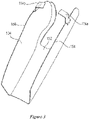
- FIG. 1 illustrates a hearing device incorporating a conformal folded antenna in accordance with various embodiments.
- the hearing device 100 is of a behind-the-ear design.
- the hearing device 100 includes an enclosure in the form of a shell 102 which includes a first end 107 and an opposing second end 109.
- the shell 102 also includes a bottom 111, a removable top or cap (removed in Figure 1 ) opposing the bottom 111, and opposing sides 124 and 126, all of which extend between the first and second ends 107 and 109.
- the shell 102 has a volume that is at a maximum near the first end 107, at a minimum near the second end 109, and incrementally reduces along a longitudinal axis defined between the first and second ends 107 and 109.
- a battery 108 is shown positioned proximate the first end 107.
- the first end 107 can be hingedly connected to the shell 102 or otherwise configured to move between closed and open positions for installing and removing the battery 108.
- a spine 110 extends longitudinally within the shell 102 between the battery 108 and the second end 109.
- the spine 110 is a structure inside the shell 102 that supports the flexible circuit substrate and electronics 106 of the hearing device 100.
- the spine 110 includes supports or struts that are connected to interior surfaces 103 of the shell 102 and positionally fix the spine 110 within the shell 102.
- a folded antenna 104 is disposed inside the shell 102 and has a shape that generally conforms to interior surfaces 103 of the shell 102. As such, the shape of the folded antenna 104 generally follows the shape of the shell wall.
- the folded antenna 104 is a substantially solid, folded structure that extends longitudinally along interior surfaces 103 of the shell 102.
- the folded antenna 104 can incorporate a metal mesh or grid surrounded by solid metal.
- a metal mesh or grid structure can be placed within an aperture of a metal frame that together define the folded antenna 104. Incorporating a metal mesh or grid pattern in the antenna structure can provide for a reduction in the area of the folded antenna 104.
- the folded antenna 104 shown in Figure 1 extends longitudinally along the bottom 111 and along the opposing sides 124 and 126 of the shell 102 between the first and second ends 107 and 109. As shown, the folded antenna 104 extends along nearly the entire axial length of the shell 102 (e.g., > 90% of the shell's axial length). In some embodiments, the folded antenna 104 can extend along most, but not all, of the axial length of the shell 102 (e.g., between about 60% and 80% of the shell's axial length, such as 70%). In other embodiments, the folded antenna 104 can extend along an appreciable percentage of the axial length of the shell 102 (e.g., between about 30% and 50% of the shell's axial length, such as 40%).
- the folded antenna 104 has a first end 158, a second and 160, and a belly 152 that extends axially between the first and second ends 158 and 160.
- the folded antenna 104 includes opposing first and second sides 154 and 156 that extend from the belly 152 at an angle (e.g., an acute angle).
- the belly 152 can define a bottom or a top of the antenna 104. In the embodiments shown in Figures 1-3 , for example, the belly 152 defines a bottom of the antenna 104.
- the folded antenna 104 can have a "taco" shape in accordance with some embodiments.
- the folded antenna 104 can have a saddle shape in accordance with some embodiments.
- the folded antenna 104 can have a generally U-shaped cross-section, for example. It is understood that the description of the folded antenna 104 as having a taco or saddle shape is for illustrative, non-limiting purposes, and that many other shapes or configurations of the folded antenna 104 are contemplated.
- the folded antenna 104 can be described as a unique type of electrically small loop antenna, symmetric folded patch antenna, magnetic dipole antenna, or differentially fed planar inverted F antenna or PIFA.
- the folded antenna 104 can have a deep profile, in which the opposing first and second sides 154 and 156 extend along a major (e.g., > 50%) portion or the entirety of the first and second sides 124 and 126 of the shell 102 (e.g., in the y-direction). In other embodiments, the folded antenna 104 can have a shallow profile, in which the opposing first and second sides 154 and 156 extend along a minor (e.g., ⁇ 50%) portion of the first and second sides 124 and 126 of the shell 102.
- the belly 152 of the folded antenna 104 can be curved along a longitudinal axis (e.g., along the z-axis in the +/- y-direction) of the antenna 104, allowing the belly 152 to conform to the curvature of the shell 102. More particularly, the belly 152 can have minima of curvature (or maxima depending on antenna orientation) at the first and second ends 158 and 160 and a maxima (or minima depending on antenna orientation) between the two ends 158 and 160. The belly 152 can also be curved relative to the longitudinal axis (e.g., left or right of the z-axis in the +/- x-direction) of the folded antenna 104.
- the folded antenna 104 is positioned in close proximity to interior surfaces 103 of the shell 102 so that the folded antenna 104 encompasses at least part of the spine 110 and at least some of the electronics 106 of the hearing device 100.
- the folded antenna 104 encompasses at least part of the spine 110, such as in the case of a shallow folded antenna 104.
- the folded antenna 104 encompasses the spine 110, all of the electronics 106, and the battery 108 of the hearing device 100.
- the components of the shell 102 considered encompassed by the folded antenna 104 are those components captured between the opposing sides 154 and 156 of the antenna 104.
- components of the shell 102 considered encompassed by the folded antenna 104 are those components (e.g., spine 110 and/or electronics 106) that effectively become part of the matching network that serves to tune the antenna 104.
- the opposing sides 154 and 156 of the folded antenna 104 form an elongated gap 101 that faces the top (removed in Figure 1 ) of the shell 102.
- the elongated gap 101 serves as the effective radiator of the folded antenna 104.
- the belly 152 of the folded antenna 104 defines a bottom that is situated at or adjacent to the bottom 111 of the shell 102.
- the elongated gap 101 is oriented upwards from the wearer's ear towards the top of the head.
- a plane (e.g., a y-z plane) passing vertically through the elongated gap 101 is aligned substantially parallel with the wearer's head adjacent the ear.
- the folded antenna 104 With the hearing device 100 positioned on a wearer's ear/head in this orientation, the folded antenna 104 generates an electric field in a direction that can readily facilitate ear-to-ear communication with a hearing device positioned on the wearer's other ear, and provides an increase in performance far from the wearer's head.
- the folded antenna 104 in the shell 102 generates substantial amount of electric field that propagates parallel to the wearer's head with a perpendicular electric field polarization, which advantageously results in the generation of creeping waves that can propagate along the surface of the wearer's head to a hearing device positioned on the wearer's opposite ear.
- the direction of electric field propagation is parallel to the head, but the electric field polarization is normal to the wearer's head for the folded antenna 104.
- This advantage of the folded antenna 104 is particularly beneficial when incorporating a high-frequency radio, such as a 2.4 GHz BLE radio, in the hearing device 100.
- the direction of major electric field polarization of a hearing device incorporating a 2.4 GHz radio connected to a conventional dipole antenna is parallel (rather than perpendicular) to the wearer's head, which discourages production of creeping waves needed for ear-to-ear communication.
- Antenna feeds 114a and 114b electrically couple opposing sides 154 and 156 of the folded antenna 104 to a radio of the electronics 106.
- the feeds 114a and 114b attach to the folded antenna 104 at locations biased toward the ends 158 and 160, rather than the middle, of the antenna 104.
- the location of the feeds 114a and 115b can be selected to optimize the input impedance, effective length, radiation efficiency, and other characteristics of the folded antenna 104.
- FIG 2 illustrates additional features of a hearing device 200 incorporating a conformal folded antenna in accordance with various embodiments.
- a folded antenna 104 is positioned along the interior surfaces 103 of a shell 102.
- the top of the shell 102 is removed in Figure 2 to allow viewing of the interior components of the hearing device 200.
- Figure 2 shows a spine 110 positioned within the shell 102 and extending between first and second ends 107 and 109 of the shell 102.
- the spine 110 supports various electronics 106 of the hearing device 200, and has an end surface 136 that is recessed with respect to the first end 107 of the shell 102. This recess is dimensioned to receive a battery 128 (not shown).
- the spine 110 and/or the folded antenna 104 can include a number of struts that extend between the spine 110 and an interior surface 103 of the shell 102. Depending on the location of the struts, some of the struts (e.g., 120 and 122) pass through apertures of the folded antenna 104, while other struts (e.g., 132, 134, 136, 138) extend from an interior surface 103 of the shell 102 above the antenna 104 and terminate at mounting locations at the spine 110. Because the folded antenna 104 is positioned between the shell 102 and the spine 110, the folded antenna 104 can include one or more apertures through which one or more struts (e.g., 120 and 122) can pass. Portions of the struts that pass through the antenna apertures can be electrically insulated from the folded antenna structure.
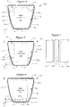
- FIG 3 illustrates a folded antenna 104 of a hearing device in accordance with various embodiments.
- the folded antenna 104 shown in Figure 3 includes first and second opposing sides 154 and 156 and a truncated belly 152 connecting the first and second opposing sides 154 and 156.
- the first and second opposing sides 154 and 156 have an axial length that extends beyond an axial length of the belly 152.
- Portions of the first and second opposing sides 154 and 156 that extend beyond the axial length of the belly 152 can be considered antenna extensions or wings.
- Feeds 114a and 114b can be electrically connected to the antenna extensions or wings, for example.
- FIG. 4 is a cross-sectional view of a folded antenna of a hearing device in accordance with other embodiments.
- the hearing device 400 shown in Figure 4 includes a shell 402 comprising a first side 424, an opposing second side 426, a bottom 411, and a removable top 413.
- the shell 402 has a depth, d , defined between the bottom 411 and the top 413 (when attached).
- a spine Disposed within the shell 402 is a spine which supports electronics of the hearing device 400, collectively shown as spine/electronics 405.
- Feeds 418a and 418b electrically connect a folded antenna 410 disposed within the shell 402 with a radio of the spine/electronics 405.
- the folded antenna 410 is shaped to generally conform to interior surfaces 403 of the shell 402, and encompasses at least part of the spine/electronics 405 of the hearing device 400.
- the folded antenna 410 shown in Figure 4 comprises a belly 416 that extends along the bottom 411 of the shell 402 and generally conforms to the shape of the bottom 411. Extending from the belly 416 of the folded antenna 410 are first and second opposing sides 414 and 415. The first and second opposing sides 414 and 415 extend along and generally conform to the shape of first and second sides 424 and 426 of the shell 402. Although not shown in the cross-sectional view of Figure 4 (and other figures), it is understood that the folded antenna 410 extends axially (e.g., into and out of the page, such as along the z-axis shown in Figure 1 ) along a longitudinal axis of shell 402.
- the folded antenna 410 has an elongated gap 401 defined between opposing first and second sides 414 and 415 of the antenna 410.
- the elongated gap 401 faces the top 413 of the shell 402.
- the first and second opposing sides 414 and 415 of the folded antenna 402 have a height, h, which is about the same as the depth, d, of the shell 402.
- the first and second opposing sides 414 and 415 have a height, h, which is between about 50% and 100% of the depth, d, of the shell 402 (e.g., > 80% or 90% of d).
- FIG. 5 illustrates a folded antenna of a hearing device in accordance with some embodiments.
- the hearing device 500 shown in Figure 5 includes a shell 402 comprising a first side 424, an opposing second side 426, a bottom 411, and a removable top 413.
- the shell 402 has a depth, d , defined between the bottom 411 and the top 413 (when attached).
- Disposed within the shell 402 is a spine which supports electronics of the hearing device 500, collectively shown as spine/electronics 405.
- Feeds 518a and 518b electrically connect a folded antenna 510 disposed within the shell 402 with a radio of the spine/electronics 405.
- the folded antenna 510 is shaped to generally conform to interior surfaces 403 of the shell 402, and encompasses at least part of the spine/electronics 405 of the hearing device 500.
- the folded antenna 510 shown in Figure 5 comprises a belly 516 that extends along the bottom 411 of the shell 402 and generally conforms to the shape of the bottom 411. Extending from the belly 516 are first and second opposing sides 514 and 515. The first and second opposing sides 514 and 515 extend along and generally conform to the shape of a limited portion of the first and second sides 424 and 426 of the shell 402.
- the folded antenna 510 has an elongated gap 401 defined between opposing first and second sides 514 and 515 of the antenna 510. In the embodiment shown in Figure 5 , the elongated gap 501 faces the top 413 of the shell 402.
- the first and second opposing sides 514 and 515 of the folded antenna 510 have a height, h , which is less than the depth, d, of the shell 402. More particularly, the first and second opposing sides 514 and 515 can have a height, h, which is less than about 50% of the depth, d, of the shell 402 (e.g., between ⁇ 20%-40% of d).
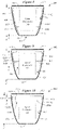
- FIG. 6 illustrates a folded antenna of a hearing device in accordance with further embodiments.
- the hearing device 600 shown in Figure 6 includes a shell 402 comprising a first side 424, an opposing second side 426, a bottom 411, and a removable top 413.
- the shell 402 has a depth, d , defined between the bottom 411 and the top 413 (when attached).
- Disposed within the shell 402 is a spine which supports electronics of the hearing device 600, collectively shown as spine/electronics 405.
- Feeds 618a and 618b electrically connect a folded antenna 610 disposed within the shell 402 with a radio of the spine/electronics 405.
- the folded antenna 610 is shaped to generally conform to interior surfaces 403 of the shell 402. According to some embodiments, the folded antenna 610 is configured to encompass at least part of the spine/electronics 405 of the hearing device 600.
- the folded antenna 610 shown in Figure 6 comprises a belly 616 that extends along the bottom 411 of the shell 402 and generally conforms to the shape of the bottom 411. Extending from the belly 616 are first and second opposing sides 614 and 615 that extend along and generally conform to the shape of a limited portion of the first and second sides 424 and 426 of the shell 402.
- the folded antenna 610 has an elongated gap 601 defined between opposing first and second sides 614 and 615 which, in the embodiment shown in Figure 6 , faces the top 413 of the shell 402.
- the first and second opposing sides 614 and 615 of the folded antenna 610 have a height, h, which is less than about one-quarter of the depth, d, of the shell 402. More particularly, the first and second opposing sides 614 and 615 can have a height, h, which is less than about 25% of the depth, d, of the shell 402 (e.g., between ⁇ 0%-20% of d).
- Figure 7 is a cross-sectional view of a portion of a hearing device that includes a folded antenna in accordance with various embodiments.
- Figure 7 shows a portion of the hearing device 400 shown in Figure 4 , but can apply to other embodiments, such as those shown in Figures 5 and 6.
- Figure 7 shows a second side 415 of a folded antenna 410 situated adjacent to a second side 426 of the hearing device's shell 402.
- An electrical insulator 419 e.g., dielectric material
- the insulator 419 can be a coating or layered material applied directly to the antenna surface.
- the insulator 419 can be a separate electrically insulating structure.
- Suitable insulator materials 419 include polyester, polyetherimide, polyimide, polytetrafluoroethylene (PTFE), silicone, tape, paper, and air, for example.
- the hearing device 800 shown in Figure 8 includes a shell 402 comprising a first side 424, an opposing second side 426, a bottom 411, and a removable top 413.
- the shell 402 has a depth, d , defined between the bottom 411 and the top 413 (when attached).
- a spine Disposed within the shell 402 is a spine which supports electronics of the hearing device 800, collectively shown as spine/electronics 405.
- Feeds 818a and 818b electrically connect a folded antenna 810 disposed within the shell 402 with a radio of the spine/electronics 405.
- the folded antenna 810 is shaped to generally conform to interior surfaces 403 of the shell 402, and encompasses at least part of the spine/electronics 405 of the hearing device 800.
- the folded antenna 810 shown in Figure 8 comprises a belly 816 that extends along the top 413 of the shell 402 and generally conforms to the shape of the top 413. Extending from the belly 816 of the folded antenna 810 are first and second opposing sides 814 and 815 that extend along and generally conform to the shape of first and second sides 424 and 426 of the shell 402.
- the folded antenna 810 has an elongated gap 801 defined between opposing first and second sides 814 and 815 which, in the embodiment of Figure 8 , faces the bottom 411 of the shell 402.
- the first and second opposing sides 814 and 815 of the folded antenna 802 have a height, h, which is about the same as the depth, d, of the shell 402. In some configurations, the first and second opposing sides 814 and 815 have a height, h, which is between about 50% and 100% of the depth, d, of the shell 402 (e.g., > 80% or 90% of d).
- the hearing device 900 shown in Figure 9 includes a shell 402 comprising a first side 424, an opposing second side 426, a bottom 411, and a removable top 413.
- the shell 402 has a depth, d , defined between the bottom 411 and the top 413 (when attached).
- a spine Disposed within the shell 402 is a spine which supports electronics of the hearing device 900, collectively shown as spine/electronics 405.
- Feeds 918a and 918b electrically connect a folded antenna 910 disposed within the shell 402 with a radio of the spine/electronics 405.
- the folded antenna 910 is shaped to generally conform to interior surfaces 403 of the shell 402, and encompasses at least part of the spine/electronics 405 of the hearing device 900.
- the folded antenna 910 shown in Figure 9 comprises a belly 916 that extends along the top 413 of the shell 402 and generally conforms to the shape of the top 413. Extending from the belly 916 of the folded antenna 910 are first and second opposing sides 914 and 915 which extend along and generally conform to the shape of a limited portion of the first and second sides 424 and 426 of the shell 402.
- the folded antenna 910 has an elongated gap 901 defined between opposing first and second sides 914 and 915 which faces the bottom 411 of the shell 402.
- the first and second opposing sides 914 and 915 of the folded antenna 902 have a height, h , which is less than the depth, d , of the shell 402. More particularly, the first and second opposing sides 914 and 915 can have a height, h, which is less than about 50% of the depth, d, of the shell 402 (e.g., between ⁇ 20%-40% of d).
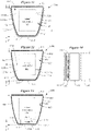
- the hearing device 1000 shown in Figure 10 includes a shell 402 comprising a first side 424, an opposing second side 426, a bottom 411, and a removable top 413.
- the shell 402 has a depth, d , defined between the bottom 411 and the top 413 (when attached).
- a spine Disposed within the shell 402 is a spine which supports electronics of the hearing device 1000, collectively shown as spine/electronics 405.
- Feeds 1018a and 1018b electrically connect a folded antenna 1010 disposed within the shell 402 with a radio of the spine/electronics 405.
- the folded antenna 1010 is shaped to generally conform to interior surfaces 403 of the shell 402. In some embodiments, the folded antenna 1010 is configured to encompass at least part of the spine/electronics 405 of the hearing device 1000.
- the folded antenna 1010 shown in Figure 10 comprises a belly 1016 that extends along the top 413 of the shell 402 and generally conforms to the shape of the top 413. Extending from the belly 1016 of the folded antenna 1010 are first and second opposing sides 1014 and 1015 that extend along and generally conform to the shape of a limited portion of the first and second sides 424 and 426 of the shell 402.
- the folded antenna 1010 has an elongated gap 1001 defined between opposing first and second sides 1014 and 1015 which faces the bottom 411 of the shell 402.
- the first and second opposing sides 1014 and 1015 of the folded antenna 1010 have a height, h, which is less than about one-third or one-quarter of the depth, d, of the shell 402.
- first and second opposing sides 1014 and 1015 can have a height, h , which is less than about 25% of the depth, d , of the shell 402 (e.g., between ⁇ 0%-20% of d ). It is noted that the embodiments shown in Figures 8-10 can incorporate an insulating coating or layer on or adjacent the folded antenna in a manner described previously with reference to Figure 7 .
- Figure 11 illustrates a hearing device incorporating a conformal folded antenna in accordance with various embodiments.
- the hearing device 1100 includes many of the structural and electrical components shown in Figure 4 .
- the embodiment of Figure 11 differs from that of Figure 4 in terms of the antenna implementation.
- the folded antenna 1110 is attached to the exterior surface 407 of the shell 402.
- the folded antenna 1110 has a shape that generally conforms to the exterior surface 407 of the shell 402, and can be attached thereto with an adhesive or other type of bonding.
- the folded antenna 1110 shown in Figure 11 and other figures can be formed as a laser direct structuring (LDS) component on the shell 402 (e.g., formed on the exterior surface 407 in Figure 11 ).
- LDS laser direct structuring
- a protective coating (not shown in Figure 11 , but see Figure 14 ) can be applied to the exterior surface of the folded antenna 1100.
- the hearing device 1100 shown in Figure 11 includes a shell 402 comprising a first side 424, an opposing second side 426, a bottom 411, and a removable top 413.
- the shell 402 has a depth, d , defined between the bottom 411 and the top 413 (when attached).
- a spine Disposed within the shell 402 is a spine which supports electronics of the hearing device 1100, collectively shown as spine/electronics 405.
- Feeds 1118a and 1118b extend through the opposing sides 424 and 426 and electrically connect a folded antenna 1110 disposed within the shell 402 with a radio of the spine/electronics 405.
- Sealing material can be used to seal the apertures in the opposing sides 424 and 426 through which the feeds 1118a and 1118b pass.
- the folded antenna 1110 is shaped to generally conform to exterior surfaces 407 of the shell 402, and encompasses at least part of the spine/electronics 405 of the hearing device 1100.
- the folded antenna 1110 shown in Figure 11 comprises a belly 1116 that extends along the bottom 411 of the shell 402 and generally conforms to the shape of the bottom 411. Extending from the belly 1116 are first and second opposing sides 1114 and 1115, which extend along and generally conform to the shape of first and second sides 424 and 426 of the shell 402.
- the folded antenna 1110 has an elongated gap 1101 defined between the opposing first and second sides 1114 and 1115.
- the elongated gap 1101 faces the top 413 of the shell 402.
- the first and second opposing sides 1114 and 1115 of the folded antenna 1102 have a height, h, which is about the same as or slightly greater than the depth, d, of the shell 402.
- the first and second opposing sides 1114 and 1115 have a height, h , which is between about 50% and 100% of the depth, d, of the shell 402 (e.g., > 80% or 90% of d).
- FIG 12 illustrates a hearing device incorporating a conformal folded antenna in accordance with various embodiments.
- the hearing device 1200 shown in Figure 12 includes a shell 402 comprising a first side 424, an opposing second side 426, a bottom 411, and a removable top 413.
- the shell 402 has a depth, d , defined between the bottom 411 and the top 413 (when attached).
- a spine Disposed within the shell 402 is a spine which supports electronics of the hearing device 1200, collectively shown as spine/electronics 405.
- Feeds 1218a and 1218b extend through the opposing sides 424 and 426 and electrically connect a folded antenna 1210 disposed within the shell 402 with a radio of the spine/electronics 405.
- the folded antenna 1210 is shaped to generally conform to exterior surfaces 407 of the shell 402, and encompasses at least part of the spine/electronics 405 of the hearing device 1200.
- the folded antenna 1210 shown in Figure 12 comprises a belly 1216 that extends along the bottom 411 of the shell 402 and generally conforms to the shape of the bottom 411. Extending from the belly 1216 of the folded antenna 1210 are first and second opposing sides 1214 and 1215, which extend along and generally conform to the shape of a limited portion of the first and second sides 424 and 426 of the shell 402.
- the folded antenna 1210 has an elongated gap 1201 defined between the opposing first and second sides 1214 and 1215. In the embodiment shown in Figure 12 , the elongated gap 1201 faces the top 413 of the shell 402.
- the first and second opposing sides 1214 and 1215 of the folded antenna 1210 have a height, h , which is less than the depth, d, of the shell 402. More particularly, the first and second opposing sides 1214 and 1215 can have a height, h, which is less than about 50% of the depth, d, of the shell 402 (e.g., between ⁇ 20%-40% of d).
- FIG 13 illustrates a hearing device incorporating a conformal folded antenna in accordance with some embodiments.
- the hearing device 1300 shown in Figure 13 includes a shell 402 comprising a first side 424, an opposing second side 426, a bottom 411, and a removable top 413.
- the shell 402 has a depth, d , defined between the bottom 411 and the top 413 (when attached).
- a spine Disposed within the shell 402 is a spine which supports electronics of the hearing device 1300, collectively shown as spine/electronics 405.
- Feeds 1318a and 1318b extend through the opposing sides 424 and 426 and electrically connect a folded antenna 1310 disposed within the shell 402 with a radio of the spine/electronics 405.
- the folded antenna 1310 is shaped to generally conform to exterior surfaces 407 of the shell 402. In some embodiments, the folded antenna 1300 is configured to encompass at least part of the spine/electronics 405 of the hearing device 1300.
- the folded antenna 1310 shown in Figure 13 comprises a belly 1316 that extends along the bottom 411 of the shell 402 and generally conforms to the shape of the bottom 411. Extending from the belly 1316 of the folded antenna 1310 are first and second opposing sides 1314 and 1315 that extend along and generally conform to the shape of a limited portion of the first and second sides 424 and 426 of the shell 402.
- the folded antenna 1310 has an elongated gap 1301 defined between opposing first and second sides 1314 and 1315 which, in the embodiment shown in Figure 13 , faces the top 413 of the shell 402.
- the first and second opposing sides 1314 and 1315 of the folded antenna 1302 have a height, h , which is less than about one-third or one-quarter of the depth, d, of the shell 402.
- the first and second opposing sides 1314 and 1315 can have a height, h, which is less than about 25% of the depth, d, of the shell 402 (e.g., between ⁇ 0%-20% of d ).
- Figure 14 is a cross-sectional view of a portion of a hearing device that includes a folded antenna in accordance with various embodiments.
- Figure 14 shows a portion of the hearing device 1100 shown in Figure 11 , but can apply to other embodiments, such as those shown in Figures 12 and 13.
- Figure 14 shows the spine/electronics 405 of the hearing device 1100 situated adjacent the second side 426 of the shell 402.
- Figure 14 also shows a second side 1115 of a folded antenna 1110 situated adjacent the second side 426 of the shell 402.
- the folded antenna 1110 can optionally incorporate a metal mesh or grid 1117 within an aperture of each side (e.g., first and second sides 1114 and 1115) of the folded antenna 1100.
- a protective material 1119 is disposed on the exterior surface of the second side 1115 (and the first side 1114) of the folded antenna 1110.
- the protective material 1119 can be a coating or one or more layers of protective material. Suitable materials 1119 can include those listed above with reference to Figure 7 , with the understanding that aesthetics are important since the protective material 1119 would be visible.
- the hearing device 1500 shown in Figure 15 includes a shell 402 comprising a first side 424, an opposing second side 426, a bottom 411, and a removable top 413.
- the shell 402 has a depth, d , defined between the bottom 411 and the top 413 (when attached).
- a spine Disposed within the shell 402 is a spine which supports electronics of the hearing device 1500, collectively shown as spine/electronics 405.
- Feeds 1518a and 1518b extend through the opposing sides 424 and 426 and electrically connect a folded antenna 1510 disposed on the exterior of the shell 402 with a radio of the spine/electronics 405.
- the folded antenna 1510 is shaped to generally conform to exterior surfaces 407 of the shell 402, and encompasses at least part of the spine/electronics 405 of the hearing device 1500.
- the folded antenna 1510 shown in Figure 15 comprises a belly 1516 that extends along the top 413 of the shell 402 and generally conforms to the shape of the top 413. Extending from the belly 1516 of the folded antenna 1510 are first and second opposing sides 1514 and 1515 that extend along and generally conform to the shape of first and second sides 424 and 426 of the shell 402.
- the folded antenna 1510 has an elongated gap 1501 defined between opposing first and second sides 1514 and 1515 whichfaces the bottom 411 of the shell 402.
- the first and second opposing sides 1514 and 1515 of the folded antenna 1510 have a height, h , which is about the same as the depth, d , of the shell 402 (e.g., +/- 10%). In some configurations, the first and second opposing sides 1514 and 1515 have a height, h, which is between about 50% and 100% of the depth, d, of the shell 402 (e.g., > 80% or 90% of d).
- the hearing device 1600 shown in Figure 16 includes a shell 402 comprising a first side 424, an opposing second side 426, a bottom 411, and a removable top 413.
- the shell 402 has a depth, d , defined between the bottom 411 and the top 413 (when attached).
- a spine Disposed within the shell 402 is a spine which supports electronics of the hearing device 1600, collectively shown as spine/electronics 405.
- Feeds 1618a and 1618b extend through the opposing sides 424 and 426 and electrically connect a folded antenna 1610 disposed on the exterior of the shell 402 with a radio of the spine/electronics 405.
- the folded antenna 1610 is shaped to generally conform to exterior surfaces 407 of the shell 402, and encompasses at least part of the spine/electronics 405 of the hearing device 1600.
- the folded antenna 1610 shown in Figure 16 comprises a belly 1616 that extends along the top 413 of the shell 402 and generally conforms to the shape of the top 413. Extending from the belly 1616 of the folded antenna 1610 are first and second opposing sides 1614 and 1615 which extend along and generally conform to the shape of a limited portion of the first and second sides 424 and 426 of the shell 402.
- the folded antenna 1610 has an elongated gap 1601 defined between opposing first and second sides 1614 and 1615 which faces the bottom 411 of the shell 402.
- the first and second opposing sides 1614 and 1615 have a height, h , which is less than the depth, d, of the shell 402. More particularly, the first and second opposing sides 1614 and 1615 can have a height, h, which is less than about 50% of the depth, d, of the shell 402 (e.g., between ⁇ 20%-40% of d).
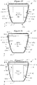
- the hearing device 1700 shown in Figure 17 includes a shell 402 comprising a first side 424, an opposing second side 426, a bottom 411, and a removable top 413.
- the shell 402 has a depth, d , defined between the bottom 411 and the top 413 (when attached).
- a spine Disposed within the shell 402 is a spine which supports electronics of the hearing device 1700, collectively shown as spine/electronics 405.
- Feeds 1718a and 1718b extend through the opposing sides 424 and 426 and electrically connect a folded antenna 1710 disposed on the exterior of the shell 402 with a radio of the spine/electronics 405.
- the folded antenna 1710 is shaped to generally conform to exterior surfaces 407 of the shell 402. In some embodiments, the folded antenna 1710 is configured to encompass at least part of the spine/electronics 405 of the hearing device 1700.
- the folded antenna 1710 shown in Figure 17 comprises a belly 1716 that extends along the top 413 of the shell 402 and generally conforms to the shape of the top 413. Extending from the belly 1716 are first and second opposing sides 1714 and 1715 that extend along and generally conform to the shape of a limited portion of the first and second sides 424 and 426 of the shell 402.
- the folded antenna 1710 has an elongated gap 1701 defined between opposing first and second sides 1714 and 1715 whichfaces the bottom 411 of the shell 402.
- the first and second opposing sides 1714 and 1715 have a height, h , which is less than about one-third or one-quarter of the depth, d, of the shell 402.
- first and second opposing sides 1714 and 1715 can have a height, h, which is less than about 25% of the depth, d, of the shell 402 (e.g., between ⁇ 0%-20% of d ).
- a protective material can be disposed on the exterior surface of the folded antennas shown in Figures 15-17 .
- the protective material can be a coating or one or more layers of protective material. Suitable materials include those listed above with reference to Figure 14 (e.g., layer(s) 1119).
- FIG 18 illustrates a folded antenna of a hearing device in accordance with further embodiments.
- the hearing device 1800 shown in Figure 18 includes a shell 402 comprising a first side 424, an opposing second side 426, a bottom 411, and a removable top 413.
- the shell 402 has a depth, d , defined between the bottom 411 and the top 413 (when attached).
- a spine Disposed within the shell 402 is a spine which supports electronics of the hearing device 1800, collectively shown as spine/electronics 405.
- Feeds 1818a and 1818b electrically connect a folded antenna 1810 disposed on and within the shell 402 with a radio of the spine/electronics 405.
- the folded antenna 1810 is shaped to generally conform to exterior surfaces 407 and interior surfaces 403 of the shell 402. More specifically, the folded antenna 1810 shown in Figure 18 is disposed on exterior surfaces 407 of the shell 402 and extends at least partially along interior surfaces 403 of the shell 402. In this regard, the folded antenna 1810 may be considered a double-layer folded antenna.
- the folded antenna 1810 is configured to encompass at least part of the spine/electronics 405 of the hearing device 1800.
- the folded antenna 1810 comprises a belly 1816 that extends along the bottom 411 (exterior) of the shell 402 and generally conforms to the shape of the bottom 411. Extending from the belly 1816 are first and second opposing exterior sides 1814a and 1815a.
- the first and second opposing exterior sides 1814a and 1815a extend along and generally conform to the shape of first and second sides 424 and 426 of the shell 402.
- the first and second opposing exterior sides 1814a and 1815a wrap around respective end surfaces 404 and 406 of the first and second sides 424 and 426 and extend along at least a portion of interior surfaces 403 of the shell 402 as first and second opposing interior sides 1814b and 1815b.
- the folded antenna 1810 has an elongated gap 1801 defined between opposing first and second sides 1814a/1814b and 1815a/1815b. In the embodiment shown in Figure 18 , the elongated gap 1801 faces the top 413 of the shell 402.
- the first and second opposing exterior sides 1814a and 1815a of the folded antenna 1810 have a height, h 1 , which is about the same as the depth, d, of the shell 402 (e.g., +/- 10%).
- the first and second opposing interior sides 1814b and 1815b of the folded antenna 1810 have a height, h 2 , which can be about the same as the depth, d , of the shell 402 (e.g., +/- 10%).
- the first and second opposing interior sides 1814b and 1815b have a height, h 2 , which is between about 50% and 100% of the depth, d, of the shell 402 (e.g., > 80% or 90% of d ).
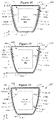
- FIG 19 illustrates a folded antenna of a hearing device in accordance with further embodiments.
- the hearing device 1900 shown in Figure 19 includes a shell 402 comprising a first side 424, an opposing second side 426, a bottom 411, and a removable top 413.
- the shell 402 has a depth, d , defined between the bottom 411 and the top 413 (when attached).
- Disposed within the shell 402 is a spine which supports electronics of the hearing device 1900, collectively shown as spine/electronics 405.
- Feeds 1918a and 1918b electrically connect a folded antenna 1910 disposed on and within the shell 402 with a radio of the spine/electronics 405.
- the folded antenna 1910 is shaped to generally conform to exterior surfaces 407 and interior surfaces 403 of the shell 402.
- the folded antenna 1910 shown in Figure 19 is disposed on exterior surfaces 407 of the shell 402 and extends at least partially along interior surfaces 403 of the shell 402.
- the folded antenna 1910 may be considered a double-layer folded antenna.
- the folded antenna 1910 is configured to encompass at least part of the spine/electronics 405 of the hearing device 1900.
- the folded antenna 1910 comprises a belly 1916 that extends along the bottom 411 (exterior) of the shell 402 and generally conforms to the shape of the bottom 411. Extending from the belly 1916 are first and second opposing exterior sides 1914a and 1915a.
- the first and second opposing exterior sides 1914a and 1915a extend along and generally conform to the shape of first and second sides 424 and 426 of the shell 402.
- the first and second opposing exterior sides 1914a and 1915a wrap around respective end surfaces 404 and 406 of the first and second sides 424 and 426 and extend along at least a portion of interior surfaces 403 of the shell 402 as first and second opposing interior sides 1914b and 1915b.
- the folded antenna 1910 has an elongated gap 1901 defined between opposing first and second sides 1914a/1914b and 1915a/1915b. In the embodiment shown in Figure 19 , the elongated gap 1901 faces the top 413 of the shell 402.
- the first and second opposing exterior sides 1914a and 1915a of the folded antenna 1910 have a height, h 1 , which is about the same as the depth, d, of the shell 402 (e.g., +/- 10%).
- the first and second opposing interior sides 1914b and 1915b of the folded antenna 1910 have a height, h 2 , which is less than the depth, d , of the shell 402.
- the first and second opposing interior sides 1914b and 1915b have a height, h 2 , which is less than about 50% of the depth, d, of the shell 402 (e.g., between ⁇ 10%-40% of d ).
- FIG 20 illustrates a folded antenna of a hearing device in accordance with some embodiments.
- the hearing device 2000 shown in Figure 20 includes a shell 402 comprising a first side 424, an opposing second side 426, a bottom 411, and a removable top 413.
- the shell 402 has a depth, d , defined between the bottom 411 and the top 413 (when attached).
- a spine Disposed within the shell 402 is a spine which supports electronics of the hearing device 2000, collectively shown as spine/electronics 405.
- Feeds 2018a and 2018b electrically connect a folded antenna 2010 disposed on and within the shell 402 with a radio of the spine/electronics 405.
- the folded antenna 2010 is shaped to generally conform to exterior surfaces 407 and interior surfaces 403 of the shell 402.
- the folded antenna 2010 shown in Figure 20 is disposed on exterior surfaces 407 of the shell 402 and extends at least partially along interior surfaces 403 of the shell 402.
- the folded antenna 2010 may be considered a double-layer folded antenna.
- the folded antenna 2010 is configured to encompass at least part of the spine/electronics 405 of the hearing device 2000.
- the folded antenna 2010 comprises a belly 2016 that extends along the bottom 411 (exterior) of the shell 402 and generally conforms to the shape of the bottom 411. Extending from the belly 2016 are first and second opposing exterior sides 2014a and 2015a.
- the first and second opposing exterior sides 2014a and 2015a extend along and generally conform to the shape of first and second sides 424 and 426 of the shell 402.
- the first and second opposing exterior sides 2014a and 2015a wrap around respective end surfaces 404 and 406 of the first and second sides 425 and 426 and extend along at least a portion of interior surfaces 403 of the shell 402 as first and second opposing interior sides 2014b and 2015b.
- the folded antenna 2010 has an elongated gap 2001 defined between opposing first and second sides 2014a/2014b and 2015a/2015b.
- the elongated gap 2001 faces the top 413 of the shell 402.
- the first and second opposing exterior sides 2014a and 2015a of the folded antenna 2010 have a height, h 1 , which is about the same as the depth, d , of the shell 402 (e.g., +/- 10%).
- the first and second opposing interior sides 2014b and 2015b of the folded antenna 2010 have a height, h 2 , which is less than about 25% of the depth, d, of the shell 402 (e.g., between ⁇ 0%-20% of d ).
- a protective material can be disposed on the exterior surface of the folded antennas shown in Figures 18-20 .
- the protective material can be a coating or one or more layers of protective material. Suitable materials include those listed above with reference to Figure 14 (e.g., layer(s) 1119).
- An electrical insulator e.g., dielectric material
- the insulator can be a coating or layered material applied directly to the antenna surface (e.g., layer(s) 419 shown in Figure 7 ).
- Embodiments of a folded antenna discussed hereinabove are configured to encompass at least some of the spine/electronics disposed within the shell of the hearing device.
- the spine and/or electronics can serve as a loading dielectric that can increase the effective length of the folded antenna.
- the spine and/or electronics disposed within the shell can also become part of the matching network that effectively tunes the folded antenna.
- portions of the folded antenna extend along at least some of the interior surfaces of the shell, which effectively serves as a tuning capacitor for the folded antenna (e.g., for tuning the input impedance through a distributed capacitance effect).
- the feed location of the folded antenna can be adjusted along the elongated gap to provide reasonable impedance to be matched relatively easily. It can be appreciated that the configuration and dimensions of the folded antenna can be adjusted to achieve desired antenna performance characteristics.
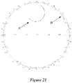
- Figure 21 is a Smith chart that demonstrates the improvement in impedance matching of the folded antenna by encompassing internal components (e.g., spine, electronics such as flex circuits, battery, receiver, etc.) disposed within the shell of the hearing device.
- Curve B shows the impedance matching characteristics of a folded antenna disposed within a hearing device shell devoid of a spine and electronics.
- Curve A shows the impedance matching characteristics of the folded antenna disposed within a hearing device which includes a spine and electronics.
- Figure 21 demonstrates that the presence of the spine and/or electronics within the shell improves the impedance matching characteristics of the folded antenna.
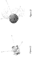
- the human head significantly impacts the performance of a folded antenna disposed in a hearing device when the hearing device is properly positioned on the ear of a wearer.
- the three-dimensional radiation pattern of a representative folded antenna in free space is illustrated in Figure 22.
- Figure 23 illustrates the three-dimensional radiation pattern of the representative folded antenna when positioned on the wearer's ear immediately adjacent the head.
- head loading significantly improves the performance of the folded antenna. More particularly, head loading makes the folded antenna form smooth approximately semi-sphere coverage as is shown in Figure 23 .
- the head-loaded folded antenna has right E-field polarization which is substantially normal to the head and a significant amount of radiated power at the hearing device/head interface plane (the y-z plane), which is important for effecting reliable ear-to-ear communication.
- the two-dimensional gain pattern of Figure 24 shows significant power is directed around the back of the head (curve A), which is an indicator that creeping waves can be launched to facilitate ear-to-ear communication.
- curve A vertical polarization to head
- curve B horizontal polarization to head
- antenna gain patterns parallel to the head e.g., the y-z plane shown in Figure 23 . Stronger creeping waves can be launched using a folded antenna because of the stronger radiation pattern directed toward the back surface of the head.
- the +x and +y axes are indicated, which correspond to x and y axes shown in Figure 23 .
- a folded antenna in accordance with embodiments of the present disclosure has about the same level of radiation efficiency in free space and on the head, as is evidenced in Table 1 below.
- Table 1 Freq (GHz) On-head Radiation Efficiency (dB) Free-space Radiation Efficiency (dB) 2.40 -7.45 -7.45 2.42 -7.45 -7.83 2.44 -7.46 -7.62 2.46 -7.39 -7.42 2.48 -7.43 -7.79
- Figure 25 provides an S-parameter comparison of a folded antenna on-head (curve A) and in free space (curve B).
- Figure 25 shows an improved impedance matching condition when the folded antenna is properly positioned on the wearer's ear immediately adjacent the head.
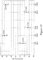
- Figure 26 shows the graphical results of this experiment.
- two different antenna topologies were evaluated; a conventional dipole antenna (curve A) and a folded antenna (curve B) implemented in accordance with the present disclosure.
- the graph of Figure 26 is divided between the channels on the left ear and channels on the right ear.
- the frequency associated with each channel can be calculated using the formula 2402 MHz + (2 x Channel Number) in MHz.
- Symmetry between left and right channels can be evaluated by comparing the TRP value for a given antenna topology at corresponding left and right channel numbers.
- left and right channel number 19 for the dipole antenna (curve A) has corresponding TRP values of ⁇ -23 and ⁇ -21 dBm, indicating asymmetric performance of approximately 2 dBm.
- the folded antenna (curve B) shows superior symmetric performance between left and right channels (e.g., ⁇ ⁇ 0.5 dBm).
- the data shown in Figure 28 demonstrates that the folded antenna has superior TRP (stays above -10 dBm across the frequency band) and excellent symmetric performance for left and right sides on the head.
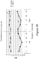
- FIG. 27 The mean E2E path gain (in dB) for each antenna topology is plotted in Figure 27 , along with an interval indicative of the standard deviation associated with each mean value.
- the antenna topologies subject to evaluation include a BTE dipole antenna (A), a BTE folded antenna of the present disclosure (B), another dipole antenna (C), a RIC Dipole antenna (D), and a RIC folded antenna of the present disclosure (E).
- the data shown in Figure 27 demonstrates that the folded antennas (B) and (E) significantly outperform all of the conventional antennas in terms of E2E path gain.
- the folded antennas (B) and (E) perform at least 20 dB better than the conventional dipole antennas (A), (C), and (D).
- Figure 27 demonstrates that folded antennas of the present disclosure provide for superior ear-to-ear communication over conventional antenna topologies.
- a folded antenna according to the some embodiments can be a continuous unitary structure.
- the folded antenna can be a continuous structure that is substantially solid except for apertures needed to accommodate elements of the hearing device (e.g., struts, electrical/magnetic components).
- the folded antenna can be notched to mitigate interference with near-field coil antennas for other wireless communication systems of the hearing device.
- the shape of the folded antenna's edge can be optimized to meet industrial design and wireless performance requirements.
- the folded antenna constitutes a stamped metal structure. In other embodiments, the folded antenna constitutes a metal plated structure.
- the folded antenna can be plated inside and/or outside of the shell, essentially forming a solid metalized shell.
- a folded antenna according to other embodiments can be a discontinuous structure comprising a multiplicity of connected antenna portions.
- the folded antenna can be split into several parts with tight coupling between each part to make the antenna more manufacturable, for example, using flex printed circuit board technology.
- the folded antenna can comprise a conductive layer on a flexible printed circuit board.
- the folded antenna can be laser direct structuring (LDS) structure.
- LDS laser direct structuring
Landscapes
- Engineering & Computer Science (AREA)
- Computer Networks & Wireless Communication (AREA)
- Health & Medical Sciences (AREA)
- General Health & Medical Sciences (AREA)
- Neurosurgery (AREA)
- Otolaryngology (AREA)
- Physics & Mathematics (AREA)
- Acoustics & Sound (AREA)
- Signal Processing (AREA)
- Support Of Aerials (AREA)
- Details Of Aerials (AREA)
Description
- This application relates generally to hearing devices, including hearing aids and other hearables.
- Hearing instruments can incorporate a radio and an antenna to wirelessly communicate with other devices. For example, a hearing instrument may receive audio from a transceiver which is connected to a television or a radio. This audio may be reproduced by the speaker of the hearing instrument, hereby allowing the wearer to hear the audio source without having to disturb others by turning up the volume on the audio source. Hearing instruments positioned on left and right ears of a wearer can be configured to communicate using an ear-to-ear link in addition to communicating with other devices.
-
DE 10 2015208845 discloses a hearing device comprising a housing which has a mounting opening and a housing cover for closing the mounting opening. -
US2014/010394 discloses a behind the ear (BTE) hearing aid including: a microphone; a signal processor; a receiver; a partition plane extending between a first side of the hearing aid and a second side of the hearing aid; and a transceiver for wireless data communication interconnected with an antenna for electromagnetic field emission and electromagnetic field reception. -
EP2680613 discloses an in-the-ear hearing aid comprising a microphone for reception of sound and conversion of the received sound into a corresponding audio signal, a signal processor for processing the audio signal, a receiver for converting the audio signal to an output sound signal, a face plate, and a transceiver for wireless data communication being interconnected with an antenna for emission and reception of an electromagnetic field. - There is provided in the following a hearing device adapted to be worn by a wearer, comprising:
- a shell configured for placement on an exterior surface of an ear of the wearer, the shell comprising a first end, a second end, a bottom, a top, and opposing sides, wherein the bottom, top, and opposing sides extend between the first and second ends;
- circuitry provided within the shell comprising at least a microphone, signal processing circuitry, radio circuitry, and a power source; and
- a folded antenna coupled to the radio circuitry, comprising opposing first and second sides conforming to the surfaces of the of the opposing sides of the shell extending from a belly conforming to the shell bottom, the folded antenna extending longitudinally along the bottom and along the opposing sides of the shell between the first and second ends, the folded antenna encompassing at least some of the circuitry and forming an elongated gap between opposing sides of the antenna, the elongated gap facing the top.
- The above summary is not intended to describe each disclosed embodiment or every implementation of the present disclosure. The figures and the detailed description below more particularly exemplify illustrative embodiments.
- Throughout the specification reference is made to the appended drawings wherein:
-
Figure 1 illustrates a hearing device incorporating a folded antenna in accordance with various embodiments; -
Figure 2 illustrates additional features of a hearing device incorporating a folded antenna in accordance with various embodiments; -
Figure 3 illustrates a folded antenna of a hearing device in accordance with various embodiments; -
Figure 4 illustrates a folded antenna disposed in the interior of a hearing device in accordance with various embodiments; -
Figure 5 illustrates a folded antenna disposed in the interior of a hearing device in accordance with some embodiments; -
Figure 6 illustrates a folded antenna disposed in the interior of a hearing device in accordance with other embodiments; -
Figure 7 is a cross-sectional view that shows a folded antenna disposed in the interior of a hearing device in accordance with various embodiments; -
Figure 8 illustrates an alternative folded antenna disposed in the interior of a hearing device; -
Figure 9 illustrates an alternative folded antenna disposed in the interior of a hearing device; -
Figure 10 illustrates an alternative folded antenna disposed in the interior of a hearing device; -
Figure 11 illustrates a folded antenna disposed on the exterior of a hearing device in accordance with various embodiments; -
Figure 12 illustrates a folded antenna disposed on the exterior of a hearing device in accordance with some embodiments; -
Figure 13 illustrates a folded antenna disposed on the exterior of a hearing device in accordance with other embodiments; -
Figure 14 is a cross-sectional view that shows a folded antenna disposed on the exterior of a hearing device in accordance with various embodiments; -
Figure 15 illustrates an alternative folded antenna disposed on the exterior of a hearing device; -
Figure 16 illustrates an alternative folded antenna disposed on the exterior of a hearing device; -
Figure 17 illustrates an alternative folded antenna disposed on the exterior of a hearing device; -
Figure 18 illustrates a folded antenna disposed on the exterior and in the interior of a hearing device in accordance with various embodiments; -
Figure 19 illustrates a folded antenna disposed on the exterior and in the interior of a hearing device in accordance with some embodiments; -
Figure 20 illustrates a folded antenna disposed on the exterior and in the interior of a hearing device in accordance with other embodiments; -
Figure 21 is a Smith chart that shows an improvement in impedance matching of a folded antenna by encompassing internal components disposed within a hearing device in accordance with various embodiments; -
Figure 22 illustrates the three-dimensional radiation pattern of a folded antenna in free space in accordance with various embodiments; -
Figure 23 illustrates the three-dimensional radiation pattern of a folded antenna when positioned on the wearer's ear immediately adjacent the head in accordance with various embodiments; -
Figure 24 is a two-dimensional gain pattern at the y-z plane showing significant power radiated by a folded antenna is directed around the back of the head to facilitate ear-to-ear communication in accordance with various embodiments; -
Figure 25 provides a Smith chart of a folded antenna on-head and in free space in accordance with various embodiments; -
Figure 26 shows plots of total radiated power (TRP) for different antenna topologies including a folded antenna according to various embodiments; and -
Figure 27 shows ear-to-ear path gain data for different antenna topologies including a folded antenna according to various embodiments. - The figures are not necessarily to scale. Like numbers used in the figures refer to like components. However, it will be understood that the use of a number to refer to a component in a given figure is not intended to limit the component in another figure labeled with the same number.
- It is understood that the embodiments described herein may be used with any hearing device without departing from the scope of this disclosure. The devices depicted in the figures are intended to demonstrate the subject matter, but not in a limited, exhaustive, or exclusive sense. It is also understood that the present subject matter can be used with a device designed for use in or on the right ear or the left ear or both ears of the wearer.
- Conventional hearing instruments typically include a dipole antenna. Achieving reliable ear-to-ear (E2E) communication using conventional dipole antenna is problematic without compromises such as battery life and latency. Moreover, the major electric field polarization of a conventional dipole antenna in a hearing instrument is parallel to the wearer's head, which inhibits launching of creeping waves required for E2E communications at 2.4 GHz. In addition, head loading leads to at least a 3 dB radiation efficiency loss in conventional dipole antennas.
- Another problem is the increasing difficulty of a dipole antenna design in a smaller hearing instrument with a greater number of functionalities. A dipole antenna requires a half wavelength length approximately 62 mm at 2.4 GHz in free space. A more compact hearing instrument inevitably makes the antenna closer to more components. This closer proximity worsens the antenna performance due to stronger coupling along the antenna structures, increases the difficulties of antenna design, measurement, and assembly, and magnifies the degree of uncertainty. Additionally, current dipole antennas used in hearing instruments are not symmetric in order to accommodate different components along antenna arms and to increase the physical length of the antenna, leading to different TRP performance between hearing devices worn on left and right ears of a wearer.
- The disclosure is directed to a hearing device which incorporates a folded antenna that generally conforms to surfaces of a shell of the hearing device. In some embodiments, the folded antenna is disposed completely within the shell of the hearing device. In other embodiments, the folded antenna is disposed completely outside the shell of the hearing device, with feeds extending through the shell wall to electrically connect with the folded antenna. In further embodiments, portions of the folded antenna are disposed inside and outside of the shell. In some embodiments, the folded antenna can be incorporated within the shell wall as an internal component of the wall. Embodiments of a folded antenna overcome the deficiencies of conventional dipole antenna discussed above.
- Hearing devices of the present disclosure can incorporate a folded antenna coupled to a high-frequency radio, such as a 2.4 GHz radio. The folded antenna can cooperate with a radio that conforms to an IEEE 802.11 (e.g., WiFi®) or Bluetooth® (e.g., BLE, Bluetooth® 4. 2 or 5.0) specification, for example. It is understood that a folded antenna may also be incorporated in hearing devices that employ other radios, such as a 900 MHz radio. Hearing devices that incorporate a folded antenna of the present disclosure can be configured communicate and interact with a wireless assistive listening system. Wireless assistive listening systems are useful in a variety of situations and venues where listening by persons with impaired hearing have difficulty discerning sound (e.g., a person speaking or an audio broadcast or presentation). Wireless assistive listening systems can be useful at venues such as theaters, museums, convention centers, music halls, classrooms, restaurants, conference rooms, bank teller stations or drive-up windows, point-of-purchase locations, and other private and public meeting places.
- The term hearing devices refers to a wide variety of devices that can aid a person with impaired hearing. Hearing devices of the present disclosure include hearables (e.g., wearable earphones, headphones, virtual reality headsets), hearing aids (e.g., hearing instruments), cochlear implants, and bone-conduction devices, for example. Hearing devices can include a housing or shell within which various internal components are disposed. Typical internal components of a hearing device can include a signal processor, memory, power management circuitry, one or more communication devices (e.g., a radio and a near-field magnetic induction device), one or more antennas, one or more microphones, and a receiver/speaker, for example. Hearing devices can incorporate a communication device, such as a BLE transceiver, which can provide for enhanced connectivity with assistive listening systems. Hearing devices include, but are not limited to, behind-the-ear (BTE), in-the-ear (ITE), in-the-canal (ITC), invisible-in-canal (IIC), receiver-in-canal (RIC), receiver-in-the-ear (RITE) or completely-in-the-canal (CIC) type hearing devices. Hearing devices can also be referred to as assistive listening devices in the context of assistive listening systems. Throughout this disclosure, reference is made to a "hearing device," which is understood to refer to a single hearing device or a pair of hearing devices.
-
Figure 1 illustrates a hearing device incorporating a conformal folded antenna in accordance with various embodiments. In the embodiment shown inFigure 1 , thehearing device 100 is of a behind-the-ear design. Thehearing device 100 includes an enclosure in the form of ashell 102 which includes afirst end 107 and an opposingsecond end 109. Theshell 102 also includes a bottom 111, a removable top or cap (removed inFigure 1 ) opposing the bottom 111, and opposingsides Figure 1 , theshell 102 has a volume that is at a maximum near thefirst end 107, at a minimum near thesecond end 109, and incrementally reduces along a longitudinal axis defined between the first and second ends 107 and 109. Abattery 108 is shown positioned proximate thefirst end 107. Thefirst end 107 can be hingedly connected to theshell 102 or otherwise configured to move between closed and open positions for installing and removing thebattery 108. - A spine 110 (best seen in
Figure 2 ) extends longitudinally within theshell 102 between thebattery 108 and thesecond end 109. Thespine 110 is a structure inside theshell 102 that supports the flexible circuit substrate andelectronics 106 of thehearing device 100. Thespine 110 includes supports or struts that are connected tointerior surfaces 103 of theshell 102 and positionally fix thespine 110 within theshell 102. - In the embodiment shown in
Figure 1 , a foldedantenna 104 is disposed inside theshell 102 and has a shape that generally conforms tointerior surfaces 103 of theshell 102. As such, the shape of the foldedantenna 104 generally follows the shape of the shell wall. The foldedantenna 104 is a substantially solid, folded structure that extends longitudinally alonginterior surfaces 103 of theshell 102. In some embodiments, the foldedantenna 104 can incorporate a metal mesh or grid surrounded by solid metal. For example, a metal mesh or grid structure can be placed within an aperture of a metal frame that together define the foldedantenna 104. Incorporating a metal mesh or grid pattern in the antenna structure can provide for a reduction in the area of the foldedantenna 104. - The folded
antenna 104 shown inFigure 1 extends longitudinally along the bottom 111 and along the opposingsides shell 102 between the first and second ends 107 and 109. As shown, the foldedantenna 104 extends along nearly the entire axial length of the shell 102 (e.g., > 90% of the shell's axial length). In some embodiments, the foldedantenna 104 can extend along most, but not all, of the axial length of the shell 102 (e.g., between about 60% and 80% of the shell's axial length, such as 70%). In other embodiments, the foldedantenna 104 can extend along an appreciable percentage of the axial length of the shell 102 (e.g., between about 30% and 50% of the shell's axial length, such as 40%). - The folded
antenna 104 has afirst end 158, a second and 160, and abelly 152 that extends axially between the first and second ends 158 and 160. The foldedantenna 104 includes opposing first andsecond sides belly 152 at an angle (e.g., an acute angle). Depending on how the foldedantenna 104 is oriented within theshell 102, thebelly 152 can define a bottom or a top of theantenna 104. In the embodiments shown inFigures 1-3 , for example, thebelly 152 defines a bottom of theantenna 104. - Using a colloquial description, the folded
antenna 104 can have a "taco" shape in accordance with some embodiments. Using a geometric description, the foldedantenna 104 can have a saddle shape in accordance with some embodiments. The foldedantenna 104 can have a generally U-shaped cross-section, for example. It is understood that the description of the foldedantenna 104 as having a taco or saddle shape is for illustrative, non-limiting purposes, and that many other shapes or configurations of the foldedantenna 104 are contemplated. Using an electrical description, the foldedantenna 104 can be described as a unique type of electrically small loop antenna, symmetric folded patch antenna, magnetic dipole antenna, or differentially fed planar inverted F antenna or PIFA. - In some embodiments, the folded
antenna 104 can have a deep profile, in which the opposing first andsecond sides second sides antenna 104 can have a shallow profile, in which the opposing first andsecond sides second sides shell 102. In addition to having two opposingsides belly 152 of the foldedantenna 104 can be curved along a longitudinal axis (e.g., along the z-axis in the +/- y-direction) of theantenna 104, allowing thebelly 152 to conform to the curvature of theshell 102. More particularly, thebelly 152 can have minima of curvature (or maxima depending on antenna orientation) at the first and second ends 158 and 160 and a maxima (or minima depending on antenna orientation) between the two ends 158 and 160. Thebelly 152 can also be curved relative to the longitudinal axis (e.g., left or right of the z-axis in the +/- x-direction) of the foldedantenna 104. - The folded
antenna 104 is positioned in close proximity tointerior surfaces 103 of theshell 102 so that the foldedantenna 104 encompasses at least part of thespine 110 and at least some of theelectronics 106 of thehearing device 100. In some embodiments, the foldedantenna 104 encompasses at least part of thespine 110, such as in the case of a shallow foldedantenna 104. As shown, the foldedantenna 104 encompasses thespine 110, all of theelectronics 106, and thebattery 108 of thehearing device 100. The components of theshell 102 considered encompassed by the foldedantenna 104 are those components captured between the opposingsides antenna 104. In an electrical context, components of theshell 102 considered encompassed by the foldedantenna 104 are those components (e.g.,spine 110 and/or electronics 106) that effectively become part of the matching network that serves to tune theantenna 104. - The opposing
sides antenna 104 form anelongated gap 101 that faces the top (removed inFigure 1 ) of theshell 102. Theelongated gap 101 serves as the effective radiator of the foldedantenna 104. In this orientation, thebelly 152 of the foldedantenna 104 defines a bottom that is situated at or adjacent to the bottom 111 of theshell 102. As shown, theelongated gap 101 is oriented upwards from the wearer's ear towards the top of the head. A plane (e.g., a y-z plane) passing vertically through theelongated gap 101 is aligned substantially parallel with the wearer's head adjacent the ear. With thehearing device 100 positioned on a wearer's ear/head in this orientation, the foldedantenna 104 generates an electric field in a direction that can readily facilitate ear-to-ear communication with a hearing device positioned on the wearer's other ear, and provides an increase in performance far from the wearer's head. - More particularly, and with the
hearing device 100 properly positioned on the wearer's ear, the foldedantenna 104 in theshell 102 generates substantial amount of electric field that propagates parallel to the wearer's head with a perpendicular electric field polarization, which advantageously results in the generation of creeping waves that can propagate along the surface of the wearer's head to a hearing device positioned on the wearer's opposite ear. In other words, the direction of electric field propagation is parallel to the head, but the electric field polarization is normal to the wearer's head for the foldedantenna 104. This advantage of the foldedantenna 104 is particularly beneficial when incorporating a high-frequency radio, such as a 2.4 GHz BLE radio, in thehearing device 100. As was discussed previously, the direction of major electric field polarization of a hearing device incorporating a 2.4 GHz radio connected to a conventional dipole antenna is parallel (rather than perpendicular) to the wearer's head, which discourages production of creeping waves needed for ear-to-ear communication. - Antenna feeds 114a and 114b electrically
couple opposing sides antenna 104 to a radio of theelectronics 106. In general, thefeeds antenna 104 at locations biased toward theends antenna 104. The location of thefeeds 114a and 115b can be selected to optimize the input impedance, effective length, radiation efficiency, and other characteristics of the foldedantenna 104. -
Figure 2 illustrates additional features of ahearing device 200 incorporating a conformal folded antenna in accordance with various embodiments. In the embodiment shown inFigure 2 , a foldedantenna 104 is positioned along theinterior surfaces 103 of ashell 102. The top of theshell 102 is removed inFigure 2 to allow viewing of the interior components of thehearing device 200.Figure 2 shows aspine 110 positioned within theshell 102 and extending between first and second ends 107 and 109 of theshell 102. Thespine 110 supportsvarious electronics 106 of thehearing device 200, and has anend surface 136 that is recessed with respect to thefirst end 107 of theshell 102. This recess is dimensioned to receive a battery 128 (not shown). - The
spine 110 and/or the foldedantenna 104 can include a number of struts that extend between thespine 110 and aninterior surface 103 of theshell 102. Depending on the location of the struts, some of the struts (e.g., 120 and 122) pass through apertures of the foldedantenna 104, while other struts (e.g., 132, 134, 136, 138) extend from aninterior surface 103 of theshell 102 above theantenna 104 and terminate at mounting locations at thespine 110. Because the foldedantenna 104 is positioned between theshell 102 and thespine 110, the foldedantenna 104 can include one or more apertures through which one or more struts (e.g., 120 and 122) can pass. Portions of the struts that pass through the antenna apertures can be electrically insulated from the folded antenna structure. -
Figure 3 illustrates a foldedantenna 104 of a hearing device in accordance with various embodiments. The foldedantenna 104 shown inFigure 3 includes first and second opposingsides truncated belly 152 connecting the first and second opposingsides Figure 3 , the first and second opposingsides belly 152. Portions of the first and second opposingsides belly 152 can be considered antenna extensions or wings.Feeds -
Figure 4 is a cross-sectional view of a folded antenna of a hearing device in accordance with other embodiments. Thehearing device 400 shown inFigure 4 includes ashell 402 comprising afirst side 424, an opposingsecond side 426, a bottom 411, and aremovable top 413. Theshell 402 has a depth, d, defined between the bottom 411 and the top 413 (when attached). Disposed within theshell 402 is a spine which supports electronics of thehearing device 400, collectively shown as spine/electronics 405.Feeds antenna 410 disposed within theshell 402 with a radio of the spine/electronics 405. The foldedantenna 410 is shaped to generally conform tointerior surfaces 403 of theshell 402, and encompasses at least part of the spine/electronics 405 of thehearing device 400. - The folded
antenna 410 shown inFigure 4 comprises abelly 416 that extends along thebottom 411 of theshell 402 and generally conforms to the shape of the bottom 411. Extending from thebelly 416 of the foldedantenna 410 are first and second opposingsides sides second sides shell 402. Although not shown in the cross-sectional view ofFigure 4 (and other figures), it is understood that the foldedantenna 410 extends axially (e.g., into and out of the page, such as along the z-axis shown inFigure 1 ) along a longitudinal axis ofshell 402. The foldedantenna 410 has an elongatedgap 401 defined between opposing first andsecond sides antenna 410. In the embodiment shown inFigure 4 , theelongated gap 401 faces the top 413 of theshell 402. The first and second opposingsides antenna 402 have a height, h, which is about the same as the depth, d, of theshell 402. In some configurations, the first and second opposingsides -
Figure 5 illustrates a folded antenna of a hearing device in accordance with some embodiments. Thehearing device 500 shown inFigure 5 includes ashell 402 comprising afirst side 424, an opposingsecond side 426, a bottom 411, and aremovable top 413. Theshell 402 has a depth, d, defined between the bottom 411 and the top 413 (when attached). Disposed within theshell 402 is a spine which supports electronics of thehearing device 500, collectively shown as spine/electronics 405.Feeds antenna 510 disposed within theshell 402 with a radio of the spine/electronics 405. The foldedantenna 510 is shaped to generally conform tointerior surfaces 403 of theshell 402, and encompasses at least part of the spine/electronics 405 of thehearing device 500. - The folded
antenna 510 shown inFigure 5 comprises abelly 516 that extends along thebottom 411 of theshell 402 and generally conforms to the shape of the bottom 411. Extending from thebelly 516 are first and second opposingsides sides second sides shell 402. The foldedantenna 510 has an elongatedgap 401 defined between opposing first andsecond sides antenna 510. In the embodiment shown inFigure 5 , the elongated gap 501 faces the top 413 of theshell 402. The first and second opposingsides antenna 510 have a height, h, which is less than the depth, d, of theshell 402. More particularly, the first and second opposingsides -
Figure 6 illustrates a folded antenna of a hearing device in accordance with further embodiments. Thehearing device 600 shown inFigure 6 includes ashell 402 comprising afirst side 424, an opposingsecond side 426, a bottom 411, and aremovable top 413. Theshell 402 has a depth, d, defined between the bottom 411 and the top 413 (when attached). Disposed within theshell 402 is a spine which supports electronics of thehearing device 600, collectively shown as spine/electronics 405.Feeds antenna 610 disposed within theshell 402 with a radio of the spine/electronics 405. The foldedantenna 610 is shaped to generally conform tointerior surfaces 403 of theshell 402. According to some embodiments, the foldedantenna 610 is configured to encompass at least part of the spine/electronics 405 of thehearing device 600. - The folded
antenna 610 shown inFigure 6 comprises abelly 616 that extends along thebottom 411 of theshell 402 and generally conforms to the shape of the bottom 411. Extending from thebelly 616 are first and second opposingsides second sides shell 402. The foldedantenna 610 has an elongatedgap 601 defined between opposing first andsecond sides Figure 6 , faces the top 413 of theshell 402. The first and second opposingsides antenna 610 have a height, h, which is less than about one-quarter of the depth, d, of theshell 402. More particularly, the first and second opposingsides -
Figure 7 is a cross-sectional view of a portion of a hearing device that includes a folded antenna in accordance with various embodiments. For purposes of illustration,Figure 7 shows a portion of thehearing device 400 shown inFigure 4 , but can apply to other embodiments, such as those shown inFigures 5 and 6. Figure 7 shows asecond side 415 of a foldedantenna 410 situated adjacent to asecond side 426 of the hearing device'sshell 402. An electrical insulator 419 (e.g., dielectric material) is disposed between thesecond side 415 of the foldedantenna 410 and the spine/electronics 405 situated within the interior of the shell. In some embodiments, theinsulator 419 can be a coating or layered material applied directly to the antenna surface. In other embodiments, theinsulator 419 can be a separate electrically insulating structure.Suitable insulator materials 419 include polyester, polyetherimide, polyimide, polytetrafluoroethylene (PTFE), silicone, tape, paper, and air, for example. - The
hearing device 800 shown inFigure 8 includes ashell 402 comprising afirst side 424, an opposingsecond side 426, a bottom 411, and aremovable top 413. Theshell 402 has a depth, d, defined between the bottom 411 and the top 413 (when attached). Disposed within theshell 402 is a spine which supports electronics of thehearing device 800, collectively shown as spine/electronics 405.Feeds antenna 810 disposed within theshell 402 with a radio of the spine/electronics 405. The foldedantenna 810 is shaped to generally conform tointerior surfaces 403 of theshell 402, and encompasses at least part of the spine/electronics 405 of thehearing device 800. - The folded
antenna 810 shown inFigure 8 comprises abelly 816 that extends along the top 413 of theshell 402 and generally conforms to the shape of the top 413. Extending from thebelly 816 of the foldedantenna 810 are first and second opposingsides second sides shell 402. The foldedantenna 810 has an elongatedgap 801 defined between opposing first andsecond sides Figure 8 , faces thebottom 411 of theshell 402. The first and second opposingsides shell 402. In some configurations, the first and second opposingsides - The
hearing device 900 shown inFigure 9 includes ashell 402 comprising afirst side 424, an opposingsecond side 426, a bottom 411, and aremovable top 413. Theshell 402 has a depth, d, defined between the bottom 411 and the top 413 (when attached). Disposed within theshell 402 is a spine which supports electronics of thehearing device 900, collectively shown as spine/electronics 405.Feeds antenna 910 disposed within theshell 402 with a radio of the spine/electronics 405. The foldedantenna 910 is shaped to generally conform tointerior surfaces 403 of theshell 402, and encompasses at least part of the spine/electronics 405 of thehearing device 900. - The folded
antenna 910 shown inFigure 9 comprises abelly 916 that extends along the top 413 of theshell 402 and generally conforms to the shape of the top 413. Extending from thebelly 916 of the foldedantenna 910 are first and second opposingsides second sides shell 402. The foldedantenna 910 has an elongatedgap 901 defined between opposing first andsecond sides bottom 411 of theshell 402. The first and second opposingsides shell 402. More particularly, the first and second opposingsides - The
hearing device 1000 shown inFigure 10 includes ashell 402 comprising afirst side 424, an opposingsecond side 426, a bottom 411, and aremovable top 413. Theshell 402 has a depth, d, defined between the bottom 411 and the top 413 (when attached). Disposed within theshell 402 is a spine which supports electronics of thehearing device 1000, collectively shown as spine/electronics 405.Feeds 1018a and 1018b electrically connect a foldedantenna 1010 disposed within theshell 402 with a radio of the spine/electronics 405. The foldedantenna 1010 is shaped to generally conform tointerior surfaces 403 of theshell 402. In some embodiments, the foldedantenna 1010 is configured to encompass at least part of the spine/electronics 405 of thehearing device 1000. - The folded
antenna 1010 shown inFigure 10 comprises abelly 1016 that extends along the top 413 of theshell 402 and generally conforms to the shape of the top 413. Extending from thebelly 1016 of the foldedantenna 1010 are first and second opposingsides second sides shell 402. The foldedantenna 1010 has an elongatedgap 1001 defined between opposing first andsecond sides bottom 411 of theshell 402. The first and second opposingsides antenna 1010 have a height, h, which is less than about one-third or one-quarter of the depth, d, of theshell 402. For example, the first and second opposingsides Figures 8-10 can incorporate an insulating coating or layer on or adjacent the folded antenna in a manner described previously with reference toFigure 7 . -
Figure 11 illustrates a hearing device incorporating a conformal folded antenna in accordance with various embodiments. In the embodiment shown inFigure 11 , thehearing device 1100 includes many of the structural and electrical components shown inFigure 4 . The embodiment ofFigure 11 differs from that ofFigure 4 in terms of the antenna implementation. In the embodiment shown inFigure 11 , the foldedantenna 1110 is attached to theexterior surface 407 of theshell 402. The foldedantenna 1110 has a shape that generally conforms to theexterior surface 407 of theshell 402, and can be attached thereto with an adhesive or other type of bonding. In some embodiments, the foldedantenna 1110 shown inFigure 11 and other figures can be formed as a laser direct structuring (LDS) component on the shell 402 (e.g., formed on theexterior surface 407 inFigure 11 ). A protective coating (not shown inFigure 11 , but seeFigure 14 ) can be applied to the exterior surface of the foldedantenna 1100. - The
hearing device 1100 shown inFigure 11 includes ashell 402 comprising afirst side 424, an opposingsecond side 426, a bottom 411, and aremovable top 413. Theshell 402 has a depth, d, defined between the bottom 411 and the top 413 (when attached). Disposed within theshell 402 is a spine which supports electronics of thehearing device 1100, collectively shown as spine/electronics 405.Feeds sides antenna 1110 disposed within theshell 402 with a radio of the spine/electronics 405. Sealing material can be used to seal the apertures in the opposingsides feeds antenna 1110 is shaped to generally conform toexterior surfaces 407 of theshell 402, and encompasses at least part of the spine/electronics 405 of thehearing device 1100. - The folded
antenna 1110 shown inFigure 11 comprises abelly 1116 that extends along thebottom 411 of theshell 402 and generally conforms to the shape of the bottom 411. Extending from thebelly 1116 are first and second opposingsides second sides shell 402. The foldedantenna 1110 has an elongatedgap 1101 defined between the opposing first andsecond sides Figure 11 , theelongated gap 1101 faces the top 413 of theshell 402. The first and second opposingsides shell 402. In some configurations, the first and second opposingsides -
Figure 12 illustrates a hearing device incorporating a conformal folded antenna in accordance with various embodiments. Thehearing device 1200 shown inFigure 12 includes ashell 402 comprising afirst side 424, an opposingsecond side 426, a bottom 411, and aremovable top 413. Theshell 402 has a depth, d, defined between the bottom 411 and the top 413 (when attached). Disposed within theshell 402 is a spine which supports electronics of thehearing device 1200, collectively shown as spine/electronics 405.Feeds sides antenna 1210 disposed within theshell 402 with a radio of the spine/electronics 405. Sealing material can be used to seal the apertures in the opposingsides feeds antenna 1210 is shaped to generally conform toexterior surfaces 407 of theshell 402, and encompasses at least part of the spine/electronics 405 of thehearing device 1200. - The folded
antenna 1210 shown inFigure 12 comprises abelly 1216 that extends along thebottom 411 of theshell 402 and generally conforms to the shape of the bottom 411. Extending from thebelly 1216 of the foldedantenna 1210 are first and second opposingsides second sides shell 402. The foldedantenna 1210 has an elongatedgap 1201 defined between the opposing first andsecond sides Figure 12 , theelongated gap 1201 faces the top 413 of theshell 402. The first and second opposingsides antenna 1210 have a height, h, which is less than the depth, d, of theshell 402. More particularly, the first and second opposingsides -
Figure 13 illustrates a hearing device incorporating a conformal folded antenna in accordance with some embodiments. Thehearing device 1300 shown inFigure 13 includes ashell 402 comprising afirst side 424, an opposingsecond side 426, a bottom 411, and aremovable top 413. Theshell 402 has a depth, d, defined between the bottom 411 and the top 413 (when attached). Disposed within theshell 402 is a spine which supports electronics of thehearing device 1300, collectively shown as spine/electronics 405.Feeds sides antenna 1310 disposed within theshell 402 with a radio of the spine/electronics 405. Sealing material can be used to seal the apertures in the opposingsides feeds antenna 1310 is shaped to generally conform toexterior surfaces 407 of theshell 402. In some embodiments, the foldedantenna 1300 is configured to encompass at least part of the spine/electronics 405 of thehearing device 1300. - The folded
antenna 1310 shown inFigure 13 comprises abelly 1316 that extends along thebottom 411 of theshell 402 and generally conforms to the shape of the bottom 411. Extending from thebelly 1316 of the foldedantenna 1310 are first and second opposingsides second sides shell 402. The foldedantenna 1310 has an elongatedgap 1301 defined between opposing first andsecond sides Figure 13 , faces the top 413 of theshell 402. The first and second opposingsides shell 402. For example, the first and second opposingsides -
Figure 14 is a cross-sectional view of a portion of a hearing device that includes a folded antenna in accordance with various embodiments. For purposes of illustration,Figure 14 shows a portion of thehearing device 1100 shown inFigure 11 , but can apply to other embodiments, such as those shown inFigures 12 and 13. Figure 14 shows the spine/electronics 405 of thehearing device 1100 situated adjacent thesecond side 426 of theshell 402.Figure 14 also shows asecond side 1115 of a foldedantenna 1110 situated adjacent thesecond side 426 of theshell 402. In some embodiments, and as shown inFigure 14 , the foldedantenna 1110 can optionally incorporate a metal mesh orgrid 1117 within an aperture of each side (e.g., first andsecond sides 1114 and 1115) of the foldedantenna 1100. Aprotective material 1119 is disposed on the exterior surface of the second side 1115 (and the first side 1114) of the foldedantenna 1110. Theprotective material 1119 can be a coating or one or more layers of protective material.Suitable materials 1119 can include those listed above with reference toFigure 7 , with the understanding that aesthetics are important since theprotective material 1119 would be visible. - The
hearing device 1500 shown inFigure 15 includes ashell 402 comprising afirst side 424, an opposingsecond side 426, a bottom 411, and aremovable top 413. Theshell 402 has a depth, d, defined between the bottom 411 and the top 413 (when attached). Disposed within theshell 402 is a spine which supports electronics of thehearing device 1500, collectively shown as spine/electronics 405.Feeds sides antenna 1510 disposed on the exterior of theshell 402 with a radio of the spine/electronics 405. Sealing material can be used to seal the apertures in the opposingsides feeds antenna 1510 is shaped to generally conform toexterior surfaces 407 of theshell 402, and encompasses at least part of the spine/electronics 405 of thehearing device 1500. - The folded
antenna 1510 shown inFigure 15 comprises abelly 1516 that extends along the top 413 of theshell 402 and generally conforms to the shape of the top 413. Extending from thebelly 1516 of the foldedantenna 1510 are first and second opposingsides second sides shell 402. The foldedantenna 1510 has an elongatedgap 1501 defined between opposing first andsecond sides bottom 411 of theshell 402. The first and second opposingsides antenna 1510 have a height, h, which is about the same as the depth, d, of the shell 402 (e.g., +/- 10%). In some configurations, the first and second opposingsides - The
hearing device 1600 shown inFigure 16 includes ashell 402 comprising afirst side 424, an opposingsecond side 426, a bottom 411, and aremovable top 413. Theshell 402 has a depth, d, defined between the bottom 411 and the top 413 (when attached). Disposed within theshell 402 is a spine which supports electronics of thehearing device 1600, collectively shown as spine/electronics 405.Feeds sides antenna 1610 disposed on the exterior of theshell 402 with a radio of the spine/electronics 405. Sealing material can be used to seal the apertures in the opposingsides feeds antenna 1610 is shaped to generally conform toexterior surfaces 407 of theshell 402, and encompasses at least part of the spine/electronics 405 of thehearing device 1600. - The folded
antenna 1610 shown inFigure 16 comprises abelly 1616 that extends along the top 413 of theshell 402 and generally conforms to the shape of the top 413. Extending from thebelly 1616 of the foldedantenna 1610 are first and second opposingsides second sides shell 402. The foldedantenna 1610 has an elongatedgap 1601 defined between opposing first andsecond sides bottom 411 of theshell 402. The first and second opposingsides shell 402. More particularly, the first and second opposingsides - The
hearing device 1700 shown inFigure 17 includes ashell 402 comprising afirst side 424, an opposingsecond side 426, a bottom 411, and aremovable top 413. Theshell 402 has a depth, d, defined between the bottom 411 and the top 413 (when attached). Disposed within theshell 402 is a spine which supports electronics of thehearing device 1700, collectively shown as spine/electronics 405.Feeds sides shell 402 with a radio of the spine/electronics 405. Sealing material can be used to seal the apertures in the opposingsides feeds exterior surfaces 407 of theshell 402. In some embodiments, the folded antenna 1710 is configured to encompass at least part of the spine/electronics 405 of thehearing device 1700. - The folded antenna 1710 shown in
Figure 17 comprises abelly 1716 that extends along the top 413 of theshell 402 and generally conforms to the shape of the top 413. Extending from thebelly 1716 are first and second opposingsides second sides shell 402. The folded antenna 1710 has an elongatedgap 1701 defined between opposing first andsecond sides bottom 411 of theshell 402. The first and second opposingsides shell 402. More particularly, the first and second opposingsides Figures 15-17 . The protective material can be a coating or one or more layers of protective material. Suitable materials include those listed above with reference toFigure 14 (e.g., layer(s) 1119). -
Figure 18 illustrates a folded antenna of a hearing device in accordance with further embodiments. Thehearing device 1800 shown inFigure 18 includes ashell 402 comprising afirst side 424, an opposingsecond side 426, a bottom 411, and aremovable top 413. Theshell 402 has a depth, d, defined between the bottom 411 and the top 413 (when attached). Disposed within theshell 402 is a spine which supports electronics of thehearing device 1800, collectively shown as spine/electronics 405.Feeds antenna 1810 disposed on and within theshell 402 with a radio of the spine/electronics 405. The foldedantenna 1810 is shaped to generally conform toexterior surfaces 407 andinterior surfaces 403 of theshell 402. More specifically, the foldedantenna 1810 shown inFigure 18 is disposed onexterior surfaces 407 of theshell 402 and extends at least partially alonginterior surfaces 403 of theshell 402. In this regard, the foldedantenna 1810 may be considered a double-layer folded antenna. The foldedantenna 1810 is configured to encompass at least part of the spine/electronics 405 of thehearing device 1800. - The folded
antenna 1810 comprises abelly 1816 that extends along the bottom 411 (exterior) of theshell 402 and generally conforms to the shape of the bottom 411. Extending from thebelly 1816 are first and second opposingexterior sides exterior sides second sides shell 402. The first and second opposingexterior sides second sides interior surfaces 403 of theshell 402 as first and second opposinginterior sides antenna 1810 has an elongatedgap 1801 defined between opposing first andsecond sides 1814a/1814b and 1815a/1815b. In the embodiment shown inFigure 18 , theelongated gap 1801 faces the top 413 of theshell 402. - The first and second opposing
exterior sides antenna 1810 have a height, h1, which is about the same as the depth, d, of the shell 402 (e.g., +/- 10%). The first and second opposinginterior sides antenna 1810 have a height, h2 , which can be about the same as the depth, d, of the shell 402 (e.g., +/- 10%). In some configurations, the first and second opposinginterior sides -
Figure 19 illustrates a folded antenna of a hearing device in accordance with further embodiments. Thehearing device 1900 shown inFigure 19 includes ashell 402 comprising afirst side 424, an opposingsecond side 426, a bottom 411, and aremovable top 413. Theshell 402 has a depth, d, defined between the bottom 411 and the top 413 (when attached). Disposed within theshell 402 is a spine which supports electronics of thehearing device 1900, collectively shown as spine/electronics 405.Feeds antenna 1910 disposed on and within theshell 402 with a radio of the spine/electronics 405. The foldedantenna 1910 is shaped to generally conform toexterior surfaces 407 andinterior surfaces 403 of theshell 402. More specifically, the foldedantenna 1910 shown inFigure 19 is disposed onexterior surfaces 407 of theshell 402 and extends at least partially alonginterior surfaces 403 of theshell 402. In this regard, the foldedantenna 1910 may be considered a double-layer folded antenna. The foldedantenna 1910 is configured to encompass at least part of the spine/electronics 405 of thehearing device 1900. - The folded
antenna 1910 comprises abelly 1916 that extends along the bottom 411 (exterior) of theshell 402 and generally conforms to the shape of the bottom 411. Extending from thebelly 1916 are first and second opposingexterior sides exterior sides second sides shell 402. The first and second opposingexterior sides second sides interior surfaces 403 of theshell 402 as first and second opposinginterior sides antenna 1910 has an elongatedgap 1901 defined between opposing first andsecond sides 1914a/1914b and 1915a/1915b. In the embodiment shown inFigure 19 , theelongated gap 1901 faces the top 413 of theshell 402. - The first and second opposing
exterior sides antenna 1910 have a height, h1, which is about the same as the depth, d, of the shell 402 (e.g., +/- 10%). The first and second opposinginterior sides antenna 1910 have a height, h2 , which is less than the depth, d, of theshell 402. In some configurations, the first and second opposinginterior sides -
Figure 20 illustrates a folded antenna of a hearing device in accordance with some embodiments. Thehearing device 2000 shown inFigure 20 includes ashell 402 comprising afirst side 424, an opposingsecond side 426, a bottom 411, and aremovable top 413. Theshell 402 has a depth, d, defined between the bottom 411 and the top 413 (when attached). Disposed within theshell 402 is a spine which supports electronics of thehearing device 2000, collectively shown as spine/electronics 405.Feeds antenna 2010 disposed on and within theshell 402 with a radio of the spine/electronics 405. The foldedantenna 2010 is shaped to generally conform toexterior surfaces 407 andinterior surfaces 403 of theshell 402. More specifically, the foldedantenna 2010 shown inFigure 20 is disposed onexterior surfaces 407 of theshell 402 and extends at least partially alonginterior surfaces 403 of theshell 402. In this regard, the foldedantenna 2010 may be considered a double-layer folded antenna. In some embodiments, the foldedantenna 2010 is configured to encompass at least part of the spine/electronics 405 of thehearing device 2000. - The folded
antenna 2010 comprises abelly 2016 that extends along the bottom 411 (exterior) of theshell 402 and generally conforms to the shape of the bottom 411. Extending from thebelly 2016 are first and second opposingexterior sides exterior sides second sides shell 402. The first and second opposingexterior sides second sides 425 and 426 and extend along at least a portion ofinterior surfaces 403 of theshell 402 as first and second opposinginterior sides antenna 2010 has an elongatedgap 2001 defined between opposing first andsecond sides 2014a/2014b and 2015a/2015b. In the embodiment shown inFigure 20 , theelongated gap 2001 faces the top 413 of theshell 402. The first and second opposingexterior sides antenna 2010 have a height, h1, which is about the same as the depth, d, of the shell 402 (e.g., +/- 10%). The first and second opposinginterior sides antenna 2010 have a height, h2 , which is less than about 25% of the depth, d, of the shell 402 (e.g., between ~0%-20% of d). - A protective material can be disposed on the exterior surface of the folded antennas shown in
Figures 18-20 . The protective material can be a coating or one or more layers of protective material. Suitable materials include those listed above with reference toFigure 14 (e.g., layer(s) 1119). An electrical insulator (e.g., dielectric material) can be disposed between interior portions of the folded antennas shown inFigures 18-12 and the spine/electronics 405. In some embodiments, the insulator can be a coating or layered material applied directly to the antenna surface (e.g., layer(s) 419 shown inFigure 7 ). - Embodiments of a folded antenna discussed hereinabove are configured to encompass at least some of the spine/electronics disposed within the shell of the hearing device. The spine and/or electronics can serve as a loading dielectric that can increase the effective length of the folded antenna. The spine and/or electronics disposed within the shell can also become part of the matching network that effectively tunes the folded antenna. In some embodiments, portions of the folded antenna extend along at least some of the interior surfaces of the shell, which effectively serves as a tuning capacitor for the folded antenna (e.g., for tuning the input impedance through a distributed capacitance effect). The feed location of the folded antenna can be adjusted along the elongated gap to provide reasonable impedance to be matched relatively easily. It can be appreciated that the configuration and dimensions of the folded antenna can be adjusted to achieve desired antenna performance characteristics.
-
Figure 21 is a Smith chart that demonstrates the improvement in impedance matching of the folded antenna by encompassing internal components (e.g., spine, electronics such as flex circuits, battery, receiver, etc.) disposed within the shell of the hearing device. Curve B shows the impedance matching characteristics of a folded antenna disposed within a hearing device shell devoid of a spine and electronics. Curve A shows the impedance matching characteristics of the folded antenna disposed within a hearing device which includes a spine and electronics.Figure 21 demonstrates that the presence of the spine and/or electronics within the shell improves the impedance matching characteristics of the folded antenna. - The human head significantly impacts the performance of a folded antenna disposed in a hearing device when the hearing device is properly positioned on the ear of a wearer. The three-dimensional radiation pattern of a representative folded antenna in free space is illustrated in
Figure 22. Figure 23 illustrates the three-dimensional radiation pattern of the representative folded antenna when positioned on the wearer's ear immediately adjacent the head. As is evident inFigures 22 and 23 , head loading significantly improves the performance of the folded antenna. More particularly, head loading makes the folded antenna form smooth approximately semi-sphere coverage as is shown inFigure 23 . The head-loaded folded antenna has right E-field polarization which is substantially normal to the head and a significant amount of radiated power at the hearing device/head interface plane (the y-z plane), which is important for effecting reliable ear-to-ear communication. - The two-dimensional gain pattern of
Figure 24 , for example, shows significant power is directed around the back of the head (curve A), which is an indicator that creeping waves can be launched to facilitate ear-to-ear communication. InFigure 24 , curve A (vertical polarization to head) and curve B (horizontal polarization to head) show antenna gain patterns parallel to the head (e.g., the y-z plane shown inFigure 23 ). Stronger creeping waves can be launched using a folded antenna because of the stronger radiation pattern directed toward the back surface of the head. It is noted that, inFigure 24 , the +x and +y axes are indicated, which correspond to x and y axes shown inFigure 23 . - It is known that conventional dipole antennas can be affected severely (e.g., at least by 3 dB) by head loading. In contrast, a folded antenna in accordance with embodiments of the present disclosure has about the same level of radiation efficiency in free space and on the head, as is evidenced in Table 1 below.
Table 1 Freq (GHz) On-head Radiation Efficiency (dB) Free-space Radiation Efficiency (dB) 2.40 -7.45 -7.45 2.42 -7.45 -7.83 2.44 -7.46 -7.62 2.46 -7.39 -7.42 2.48 -7.43 -7.79 - Moreover, head loading improves the impedance matching condition as is shown in
Figure 25. Figure 25 provides an S-parameter comparison of a folded antenna on-head (curve A) and in free space (curve B).Figure 25 shows an improved impedance matching condition when the folded antenna is properly positioned on the wearer's ear immediately adjacent the head. - An experiment was performed on a test head to compare the total radiated power for different antenna topologies.
Figure 26 shows the graphical results of this experiment. In the experiment, two different antenna topologies were evaluated; a conventional dipole antenna (curve A) and a folded antenna (curve B) implemented in accordance with the present disclosure. The graph ofFigure 26 is divided between the channels on the left ear and channels on the right ear. The frequency associated with each channel can be calculated using the formula 2402 MHz + (2 x Channel Number) in MHz. For example,Channel 38 corresponds to a frequency of 2402 MHz + (2 x 38) MHz = 2478 MHz (or 2.478 GHz). - Symmetry between left and right channels can be evaluated by comparing the TRP value for a given antenna topology at corresponding left and right channel numbers. For example, left and
right channel number 19 for the dipole antenna (curve A) has corresponding TRP values of ~-23 and ~-21 dBm, indicating asymmetric performance of approximately 2 dBm. In contrast, the folded antenna (curve B) shows superior symmetric performance between left and right channels (e.g., < ~0.5 dBm). The data shown in Figure 28 demonstrates that the folded antenna has superior TRP (stays above -10 dBm across the frequency band) and excellent symmetric performance for left and right sides on the head. - Another experiment was conducted to compare ear-to-ear path gains for different antenna topologies on 20 wearers. These data are summarized in
Figure 27 . The mean E2E path gain (in dB) for each antenna topology is plotted inFigure 27 , along with an interval indicative of the standard deviation associated with each mean value. The antenna topologies subject to evaluation include a BTE dipole antenna (A), a BTE folded antenna of the present disclosure (B), another dipole antenna (C), a RIC Dipole antenna (D), and a RIC folded antenna of the present disclosure (E). The data shown inFigure 27 demonstrates that the folded antennas (B) and (E) significantly outperform all of the conventional antennas in terms of E2E path gain. For example, the folded antennas (B) and (E) perform at least 20 dB better than the conventional dipole antennas (A), (C), and (D).Figure 27 demonstrates that folded antennas of the present disclosure provide for superior ear-to-ear communication over conventional antenna topologies. - A folded antenna according to the some embodiments can be a continuous unitary structure. For example, the folded antenna can be a continuous structure that is substantially solid except for apertures needed to accommodate elements of the hearing device (e.g., struts, electrical/magnetic components). For example, the folded antenna can be notched to mitigate interference with near-field coil antennas for other wireless communication systems of the hearing device. The shape of the folded antenna's edge can be optimized to meet industrial design and wireless performance requirements.
- In some embodiments, the folded antenna constitutes a stamped metal structure. In other embodiments, the folded antenna constitutes a metal plated structure. For example, the folded antenna can be plated inside and/or outside of the shell, essentially forming a solid metalized shell. A folded antenna according to other embodiments can be a discontinuous structure comprising a multiplicity of connected antenna portions. For example, the folded antenna can be split into several parts with tight coupling between each part to make the antenna more manufacturable, for example, using flex printed circuit board technology. For example, the folded antenna can comprise a conductive layer on a flexible printed circuit board. By way of further example, the folded antenna can be laser direct structuring (LDS) structure.
Claims (18)
- A hearing device (100, 200, 400, 500, 600, 1100, 1200, 1300, 1900, 2000) adapted to be worn by a wearer, comprising:a shell (102, 402) configured for placement on an exterior surface of an ear of the wearer, the shell (102, 402) comprising a first end, a second end, a bottom, a top, and opposing sides, wherein the bottom, top, and opposing sides extend between the first and second ends;circuitry (106) provided within the shell (102, 402) comprising at least a microphone, signal processing circuitry, radio circuitry, and a power source; anda folded antenna (104, 410, 510, 610, 1100, 1102, 1110, 1210, 1302, 1310, 1910, 2010) coupled to the radio circuitry, comprising opposing first and second sides (414, 415) conforming to the surfaces of the of the opposing sides of the shell extending from a belly (152; 416; 516; 616; 1116; 1216; 1316; 1916; 2016) conforming to the shell bottom, the folded antenna extending longitudinally along the bottom and along the opposing sides (424, 426) of the shell (102, 402) between the first and second ends, the folded antenna (104, 410, 510, 610, 1100, 1102, 1110, 1210, 1302, 1310, 1910, 2010) encompassing at least some of the circuitry and forming an elongated gap (101, 401, 501, 601, 1101, 1201, 1301, 1901, 2001) between opposing sides of the antenna, the elongated gap (101, 401, 501, 601, 1101, 1201, 1301, 1901, 2001) facing the top.
- The hearing device of claim 1, wherein:
the first and second opposing sides (154, 156) of the antenna have an axial length that extends beyond an axial length of the antenna belly (152). - The hearing device (100, 200, 400, 500, 600, 1100, 1200, 1300, 1900, 2000) of any preceding claim, wherein:
the folded antenna (104, 410, 510, 610, 1010, 1100, 1102, 1110, 1210, 1302, 1310, 1910, 2010) is disposed within the shell (102, 402); or
the folded antenna is disposed on an exterior surface of the shell. - The hearing device (100, 200, 400, 500, 600, 1100, 1200, 1300, 1900, 2000) of any preceding claim, wherein the folded antenna (104, 410, 510, 610, 1100, 1102, 1110, 1210, 1302, 1310, 1910, 2010) comprises a coating of a dielectric or protective material.
- The hearing device (100, 200, 400, 500, 600, 1100, 1200, 1300, 1900, 2000) of any preceding claim, wherein:
the folded antenna (104, 410, 510, 610, 1100, 1102, 1110, 1210, 1302, 1310, 1910, 2010) extends over at least about 50% of the opposing sides. - The hearing device (100, 200, 400, 500, 600, 1100, 1200, 1300, 1900, 2000) of any of claims 1 to 5, wherein:
the folded antenna (104, 410, 510, 610, 1100, 1102, 1110, 1210, 1302, 1310, 1910, 2010) extends over less than about 50% of the opposing sides. - The hearing device (100, 200, 400, 500, 600, 1100, 1200, 1300, 1900, 2000) of any preceding claim, wherein the folded antenna (104, 410, 510, 610, 1100, 1102, 1110, 1210, 1302, 1310, 1910, 2010) is a continuous unitary structure.
- The hearing device (100, 200, 400, 500, 600, 1100, 1200, 1300, 1900, 2000) of any preceding claim, wherein the folded antenna (104, 410, 510, 610, 1100, 1102, 1110, 1210, 1302, 1310, 1910, 2010) comprises a plurality of connected, discrete antenna portions.
- The hearing device (100, 200, 400, 500, 600, 1100, 1200, 1300, 1900, 2000) of any preceding claim, wherein the folded antenna (104, 410, 510, 610, 1100, 1102, 1110, 1210, 1302, 1310, 1910, 2010) is one of a stamped metal structure, a metal structure comprising a mesh or grid pattern, a metal plated structure, a conductive layer on a flexible printed circuit board, and a laser direct structuring (LDS) structure.
- The hearing device of any preceding claim, wherein an electric field generated by the folded antenna has an electric field polarization substantially normal to the wearer at the location of the ear.
- The hearing device (100, 200, 400, 500, 600, 1100, 1200, 1300, 1500, 1900, 2000) of any preceding claim, wherein the folded antenna (104, 410, 510, 610, 1100, 1102, 1110, 1210, 1302, 1310, 1910, 2010) is configured to generate an electric field that propagates parallel to the wearer's head with a perpendicular electric field polarization that generates creeping waves.
- The hearing device (100, 200, 400, 500, 600, 1100, 1200, 1300, 1900, 2000) of any preceding claim, wherein the folded antenna (104, 410, 510, 610, 1100, 1102, 1110, 1210, 1302, 1310, 1910, 2010) has a radiation efficiency in free space that is about the same as a radiation efficiency when the hearing device is worn by the wearer.
- The hearing device (100, 200, 400, 500, 600, 1100, 1200, 1300, 1900, 2000) of any preceding claim, wherein the circuitry encompassed by the folded antenna (104, 410, 510, 610, 810, 1100, 1102, 1110, 1210, 1302, 1310, 1910, 2010) improves impedance matching of the folded antenna (104, 410, 510, 610, 1100, 1102, 1110, 1210, 1302, 1310, 1910, 2010) relative to the folded antenna (104, 410, 510, 610, 1100, 1102, 1110, 1210, 1302, 1310, 1910, 2010) in an absence of the encompassed circuitry.
- The hearing device (100, 200, 400, 500, 600, 1100, 1200, 1300, , 1900, 2000) of any preceding claim, wherein:the folded antenna (104, 410, 510, 610, 1100, 1102, 1110, 1210, 1302, 1310, 1910, 2010) is a double-layer structure comprising a first layer continuous with or connected to a second layer;the first layer is disposed on exterior surfaces of shell (102, 402); andthe second layer is disposed on interior surfaces of the shell (102, 402).
- The hearing device (100, 200, 400, 500, 600, 1100, 1200, 1300, 1900, 2000) of any preceding claim, wherein the shell comprises a removable top or cap opposing the bottom.
- The hearing device (100, 200, 400, 500, 600, 1100, 1200, 1300, 1900, 2000) of claim 1, wherein the folded antenna (104, 410, 510, 610, 802, 810, 902, 910, 1010, 1010, 1100, 1102, 1110, 1210, 1302, 1310, 1510,1610, 1710, 1810, 1910, 2010) is configured to generate a perpendicular electric field polarization that generates creeping waves.
- The hearing device (100, 200, 400, 500, 600, 1100, 1200, 1300, 1900, 2000) of claim 15, wherein the folded antenna is configured such that the creeping waves propagate along the surface of the wearer's head to a second hearing device positioned on the wearer's second ear.
- A system comprising a left hearing device according to any preceding claim and a right hearing device according to any preceding claim, wherein a total radiated power of the left hearing device is substantially symmetric with a total radiated power of the right hearing device.
Applications Claiming Priority (1)
| Application Number | Priority Date | Filing Date | Title |
|---|---|---|---|
| US15/351,643 US10256529B2 (en) | 2016-11-15 | 2016-11-15 | Hearing device incorporating conformal folded antenna |
Publications (2)
| Publication Number | Publication Date |
|---|---|
| EP3322202A1 EP3322202A1 (en) | 2018-05-16 |
| EP3322202B1 true EP3322202B1 (en) | 2022-04-20 |
Family
ID=60327224
Family Applications (1)
| Application Number | Title | Priority Date | Filing Date |
|---|---|---|---|
| EP17201900.2A Revoked EP3322202B1 (en) | 2016-11-15 | 2017-11-15 | Hearing device incorporating conformal folded antenna |
Country Status (2)
| Country | Link |
|---|---|
| US (6) | US10256529B2 (en) |
| EP (1) | EP3322202B1 (en) |
Families Citing this family (11)
| Publication number | Priority date | Publication date | Assignee | Title |
|---|---|---|---|---|
| US10256529B2 (en) * | 2016-11-15 | 2019-04-09 | Starkey Laboratories, Inc. | Hearing device incorporating conformal folded antenna |
| DK3471198T3 (en) * | 2017-10-16 | 2021-01-11 | Widex As | ANTENNA FOR A HEARING SUPPORT DEVICE |
| US10951997B2 (en) | 2018-08-07 | 2021-03-16 | Starkey Laboratories, Inc. | Hearing device incorporating antenna arrangement with slot radiating element |
| US11902748B2 (en) | 2018-08-07 | 2024-02-13 | Starkey Laboratories, Inc. | Ear-worn electronic hearing device incorporating an antenna with cutouts |
| US10785582B2 (en) | 2018-12-10 | 2020-09-22 | Starkey Laboratories, Inc. | Ear-worn electronic hearing device incorporating an antenna with cutouts |
| US11140496B2 (en) | 2019-02-26 | 2021-10-05 | Starkey Laboratories, Inc. | Ear-worn electronic device incorporating an integrated battery/antenna module |
| US10880654B1 (en) | 2019-08-14 | 2020-12-29 | Soniphi Llc | Systems and methods for expanding sensation using temperature variations |
| WO2021097782A1 (en) * | 2019-11-22 | 2021-05-27 | Goertek Technology Co., Ltd. | Antenna, wireless earbud and electronic device |
| EP3941103B1 (en) * | 2020-07-17 | 2023-11-22 | Thomson Licensing | Method for evaluating the quality of a channel operable by a wifi access point for establishing a wifi connection with a communication device, corresponding device, computer program product and computer-readable carrier medium |
| DE102020209124A1 (en) * | 2020-07-21 | 2022-01-27 | Sivantos Pte. Ltd. | ITE hearing aid |
| GB2597971B (en) * | 2020-08-12 | 2024-03-20 | British Polythene Ltd | Improvements in or relating to container carriers |
Citations (7)
| Publication number | Priority date | Publication date | Assignee | Title |
|---|---|---|---|---|
| EP1465457A2 (en) | 2003-04-02 | 2004-10-06 | Starkey Laboratories, Inc. | Hearing aid with accessory cosmetic and functional cover |
| EP2680366A1 (en) | 2012-06-25 | 2014-01-01 | GN Resound A/S | Antenna system for a wearable computing device |
| US20140010394A1 (en) | 2012-07-06 | 2014-01-09 | Gn Resound A/S | Bte hearing aid with an antenna partition plane |
| EP2765650A1 (en) * | 2013-02-08 | 2014-08-13 | Nxp B.V. | Hearing aid antenna |
| DE102015208845B3 (en) | 2015-05-13 | 2016-08-11 | Sivantos Pte. Ltd. | hearing Aid |
| EP3148219A1 (en) | 2015-09-28 | 2017-03-29 | Oticon A/s | Hearing device |
| US20180139548A1 (en) * | 2016-11-14 | 2018-05-17 | Sivantos Pte. Ltd. | Hearing aid with electronics frame and antenna integrated therein |
Family Cites Families (28)
| Publication number | Priority date | Publication date | Assignee | Title |
|---|---|---|---|---|
| US6720923B1 (en) * | 2000-09-14 | 2004-04-13 | Stata Labs, Llc | Antenna design utilizing a cavity architecture for global positioning system (GPS) applications |
| US7097945B2 (en) | 2003-04-18 | 2006-08-29 | Macronix International Co., Ltd. | Method of reducing critical dimension bias of dense pattern and isolation pattern |
| US20050099341A1 (en) | 2003-11-12 | 2005-05-12 | Gennum Corporation | Antenna for a wireless hearing aid system |
| JP3863533B2 (en) | 2004-03-22 | 2006-12-27 | 株式会社ヨコオ | Folded antenna |
| DE102005008063B4 (en) | 2005-02-22 | 2008-05-15 | Fraunhofer-Gesellschaft zur Förderung der angewandten Forschung e.V. | antenna |
| WO2008046132A1 (en) | 2006-10-17 | 2008-04-24 | Cochlear Limited | Transcutaneous receiving antenna device for implant |
| US20090231204A1 (en) * | 2007-12-06 | 2009-09-17 | Ami Semiconductor, Inc. | Miniature antenna for wireless communications |
| US8188926B2 (en) | 2008-10-31 | 2012-05-29 | Silicon Laboratories, Inc. | Folded antenna structures for portable devices |
| US8737658B2 (en) | 2008-12-19 | 2014-05-27 | Starkey Laboratories, Inc. | Three dimensional substrate for hearing assistance devices |
| US8565457B2 (en) | 2008-12-19 | 2013-10-22 | Starkey Laboratories, Inc. | Antennas for standard fit hearing assistance devices |
| US8699733B2 (en) * | 2008-12-19 | 2014-04-15 | Starkey Laboratories, Inc. | Parallel antennas for standard fit hearing assistance devices |
| CN102013927B (en) | 2010-11-16 | 2014-09-10 | 意法·爱立信半导体(北京)有限公司 | Communication equipment and antenna testing device |
| US8587484B2 (en) | 2011-09-19 | 2013-11-19 | I-Fong Chen | Quasi-balanced fed antenna structure for reducing SAR and HAC |
| KR101185503B1 (en) | 2011-12-19 | 2012-09-24 | 에이큐 주식회사 | Nfc antenna with fold shape |
| US9408004B2 (en) | 2012-05-07 | 2016-08-02 | Starkey Laboratories, Inc. | Flex connector for a hearing assistance device |
| US20130343586A1 (en) | 2012-06-25 | 2013-12-26 | Gn Resound A/S | Hearing aid having a slot antenna |
| DK3468230T3 (en) | 2012-07-06 | 2022-08-29 | Gn Hearing As | BTE hearing aid with a balanced antenna |
| US9374650B2 (en) | 2012-07-17 | 2016-06-21 | Starkey Laboratories, Inc. | System and method for embedding conductive traces into hearing assistance device housings |
| DK2932559T3 (en) | 2012-12-12 | 2021-12-20 | Sivantos Pte Ltd | MODULAR ANTENNA FOR HEARING AID |
| EP2835862B1 (en) * | 2013-08-08 | 2019-11-13 | Nxp B.V. | Antenna |
| US9641944B2 (en) | 2013-08-16 | 2017-05-02 | Starkey Laboratories, Inc. | Method of tuning capacitance for hearing assistance device flex antenna |
| US20150071470A1 (en) | 2013-09-12 | 2015-03-12 | Starkey Laboratories, Inc. | Integrated circuit die inside a flexible circuit substrate for a hearing assistance device |
| US9641927B2 (en) * | 2015-01-12 | 2017-05-02 | Qualcomm Technologies International, Ltd. | Antennas suitable for wireless earphones |
| EP3427339B1 (en) * | 2016-03-07 | 2020-09-09 | Sivantos Pte. Ltd. | Antenna |
| US10297910B2 (en) * | 2016-10-21 | 2019-05-21 | Starkey Laboratories, Inc. | Hearing device with bowtie antenna optimized for specific band |
| US10256529B2 (en) * | 2016-11-15 | 2019-04-09 | Starkey Laboratories, Inc. | Hearing device incorporating conformal folded antenna |
| US10631109B2 (en) | 2017-09-28 | 2020-04-21 | Starkey Laboratories, Inc. | Ear-worn electronic device incorporating antenna with reactively loaded network circuit |
| US10979828B2 (en) | 2018-06-05 | 2021-04-13 | Starkey Laboratories, Inc. | Ear-worn electronic device incorporating chip antenna loading of antenna structure |
-
2016
- 2016-11-15 US US15/351,643 patent/US10256529B2/en active Active
-
2017
- 2017-11-15 EP EP17201900.2A patent/EP3322202B1/en not_active Revoked
-
2019
- 2019-01-16 US US16/249,421 patent/US10581144B2/en active Active
-
2020
- 2020-01-23 US US16/750,871 patent/US10886603B2/en active Active
- 2020-12-30 US US17/137,809 patent/US11729561B2/en active Active
-
2023
- 2023-06-27 US US18/214,822 patent/US12081947B2/en active Active
-
2024
- 2024-07-25 US US18/783,717 patent/US20250063314A1/en active Pending
Patent Citations (7)
| Publication number | Priority date | Publication date | Assignee | Title |
|---|---|---|---|---|
| EP1465457A2 (en) | 2003-04-02 | 2004-10-06 | Starkey Laboratories, Inc. | Hearing aid with accessory cosmetic and functional cover |
| EP2680366A1 (en) | 2012-06-25 | 2014-01-01 | GN Resound A/S | Antenna system for a wearable computing device |
| US20140010394A1 (en) | 2012-07-06 | 2014-01-09 | Gn Resound A/S | Bte hearing aid with an antenna partition plane |
| EP2765650A1 (en) * | 2013-02-08 | 2014-08-13 | Nxp B.V. | Hearing aid antenna |
| DE102015208845B3 (en) | 2015-05-13 | 2016-08-11 | Sivantos Pte. Ltd. | hearing Aid |
| EP3148219A1 (en) | 2015-09-28 | 2017-03-29 | Oticon A/s | Hearing device |
| US20180139548A1 (en) * | 2016-11-14 | 2018-05-17 | Sivantos Pte. Ltd. | Hearing aid with electronics frame and antenna integrated therein |
Also Published As
| Publication number | Publication date |
|---|---|
| US20230370794A1 (en) | 2023-11-16 |
| US20180138583A1 (en) | 2018-05-17 |
| US10581144B2 (en) | 2020-03-03 |
| US20190190129A1 (en) | 2019-06-20 |
| US20200203813A1 (en) | 2020-06-25 |
| US20210126352A1 (en) | 2021-04-29 |
| US12081947B2 (en) | 2024-09-03 |
| EP3322202A1 (en) | 2018-05-16 |
| US20250063314A1 (en) | 2025-02-20 |
| US10886603B2 (en) | 2021-01-05 |
| US10256529B2 (en) | 2019-04-09 |
| US11729561B2 (en) | 2023-08-15 |
Similar Documents
| Publication | Publication Date | Title |
|---|---|---|
| US12081947B2 (en) | Hearing device incorporating conformal folded antenna | |
| EP2680613B1 (en) | A hearing aid having a loop formed slot antenna | |
| US10841716B2 (en) | Hearing device with two-half loop antenna | |
| US12167202B2 (en) | Ear-worn electronic device incorporating antenna with reactively loaded network circuit | |
| US10219085B2 (en) | Antenna unit | |
| JP2018519739A (en) | Hearing aid with composite antenna | |
| US10396442B2 (en) | Ear-worn electronic device incorporating combined dipole and loop antenna | |
| CN113852900B (en) | Hearing device | |
| US11355834B2 (en) | Ear-worn electronic device incorporating an antenna substrate comprising a dielectric gel or liquid | |
| US11778394B2 (en) | Hearing device with an antenna | |
| EP3236676B1 (en) | Hearing device antenna with optimized orientation |
Legal Events
| Date | Code | Title | Description |
|---|---|---|---|
| PUAI | Public reference made under article 153(3) epc to a published international application that has entered the european phase |
Free format text: ORIGINAL CODE: 0009012 |
|
| STAA | Information on the status of an ep patent application or granted ep patent |
Free format text: STATUS: REQUEST FOR EXAMINATION WAS MADE |
|
| 17P | Request for examination filed |
Effective date: 20171115 |
|
| AK | Designated contracting states |
Kind code of ref document: A1 Designated state(s): AL AT BE BG CH CY CZ DE DK EE ES FI FR GB GR HR HU IE IS IT LI LT LU LV MC MK MT NL NO PL PT RO RS SE SI SK SM TR |
|
| AX | Request for extension of the european patent |
Extension state: BA ME |
|
| RBV | Designated contracting states (corrected) |
Designated state(s): AL AT BE BG CH CY CZ DE DK EE ES FI FR GB GR HR HU IE IS IT LI LT LU LV MC MK MT NL NO PL PT RO RS SE SI SK SM TR |
|
| STAA | Information on the status of an ep patent application or granted ep patent |
Free format text: STATUS: EXAMINATION IS IN PROGRESS |
|
| 17Q | First examination report despatched |
Effective date: 20191119 |
|
| GRAP | Despatch of communication of intention to grant a patent |
Free format text: ORIGINAL CODE: EPIDOSNIGR1 |
|
| STAA | Information on the status of an ep patent application or granted ep patent |
Free format text: STATUS: GRANT OF PATENT IS INTENDED |
|
| GRAJ | Information related to disapproval of communication of intention to grant by the applicant or resumption of examination proceedings by the epo deleted |
Free format text: ORIGINAL CODE: EPIDOSDIGR1 |
|
| GRAP | Despatch of communication of intention to grant a patent |
Free format text: ORIGINAL CODE: EPIDOSNIGR1 |
|
| INTG | Intention to grant announced |
Effective date: 20211013 |
|
| INTG | Intention to grant announced |
Effective date: 20211027 |
|
| GRAS | Grant fee paid |
Free format text: ORIGINAL CODE: EPIDOSNIGR3 |
|
| GRAA | (expected) grant |
Free format text: ORIGINAL CODE: 0009210 |
|
| STAA | Information on the status of an ep patent application or granted ep patent |
Free format text: STATUS: THE PATENT HAS BEEN GRANTED |
|
| AK | Designated contracting states |
Kind code of ref document: B1 Designated state(s): AL AT BE BG CH CY CZ DE DK EE ES FI FR GB GR HR HU IE IS IT LI LT LU LV MC MK MT NL NO PL PT RO RS SE SI SK SM TR |
|
| REG | Reference to a national code |
Ref country code: GB Ref legal event code: FG4D |
|
| REG | Reference to a national code |
Ref country code: CH Ref legal event code: EP |
|
| REG | Reference to a national code |
Ref country code: IE Ref legal event code: FG4D |
|
| REG | Reference to a national code |
Ref country code: DE Ref legal event code: R096 Ref document number: 602017056185 Country of ref document: DE |
|
| REG | Reference to a national code |
Ref country code: AT Ref legal event code: REF Ref document number: 1486105 Country of ref document: AT Kind code of ref document: T Effective date: 20220515 |
|
| REG | Reference to a national code |
Ref country code: LT Ref legal event code: MG9D |
|
| REG | Reference to a national code |
Ref country code: NL Ref legal event code: MP Effective date: 20220420 |
|
| REG | Reference to a national code |
Ref country code: AT Ref legal event code: MK05 Ref document number: 1486105 Country of ref document: AT Kind code of ref document: T Effective date: 20220420 |
|
| PG25 | Lapsed in a contracting state [announced via postgrant information from national office to epo] |
Ref country code: NL Free format text: LAPSE BECAUSE OF FAILURE TO SUBMIT A TRANSLATION OF THE DESCRIPTION OR TO PAY THE FEE WITHIN THE PRESCRIBED TIME-LIMIT Effective date: 20220420 |
|
| PG25 | Lapsed in a contracting state [announced via postgrant information from national office to epo] |
Ref country code: SE Free format text: LAPSE BECAUSE OF FAILURE TO SUBMIT A TRANSLATION OF THE DESCRIPTION OR TO PAY THE FEE WITHIN THE PRESCRIBED TIME-LIMIT Effective date: 20220420 Ref country code: PT Free format text: LAPSE BECAUSE OF FAILURE TO SUBMIT A TRANSLATION OF THE DESCRIPTION OR TO PAY THE FEE WITHIN THE PRESCRIBED TIME-LIMIT Effective date: 20220822 Ref country code: NO Free format text: LAPSE BECAUSE OF FAILURE TO SUBMIT A TRANSLATION OF THE DESCRIPTION OR TO PAY THE FEE WITHIN THE PRESCRIBED TIME-LIMIT Effective date: 20220720 Ref country code: LT Free format text: LAPSE BECAUSE OF FAILURE TO SUBMIT A TRANSLATION OF THE DESCRIPTION OR TO PAY THE FEE WITHIN THE PRESCRIBED TIME-LIMIT Effective date: 20220420 Ref country code: HR Free format text: LAPSE BECAUSE OF FAILURE TO SUBMIT A TRANSLATION OF THE DESCRIPTION OR TO PAY THE FEE WITHIN THE PRESCRIBED TIME-LIMIT Effective date: 20220420 Ref country code: GR Free format text: LAPSE BECAUSE OF FAILURE TO SUBMIT A TRANSLATION OF THE DESCRIPTION OR TO PAY THE FEE WITHIN THE PRESCRIBED TIME-LIMIT Effective date: 20220721 Ref country code: FI Free format text: LAPSE BECAUSE OF FAILURE TO SUBMIT A TRANSLATION OF THE DESCRIPTION OR TO PAY THE FEE WITHIN THE PRESCRIBED TIME-LIMIT Effective date: 20220420 Ref country code: ES Free format text: LAPSE BECAUSE OF FAILURE TO SUBMIT A TRANSLATION OF THE DESCRIPTION OR TO PAY THE FEE WITHIN THE PRESCRIBED TIME-LIMIT Effective date: 20220420 Ref country code: BG Free format text: LAPSE BECAUSE OF FAILURE TO SUBMIT A TRANSLATION OF THE DESCRIPTION OR TO PAY THE FEE WITHIN THE PRESCRIBED TIME-LIMIT Effective date: 20220720 Ref country code: AT Free format text: LAPSE BECAUSE OF FAILURE TO SUBMIT A TRANSLATION OF THE DESCRIPTION OR TO PAY THE FEE WITHIN THE PRESCRIBED TIME-LIMIT Effective date: 20220420 |
|
| PG25 | Lapsed in a contracting state [announced via postgrant information from national office to epo] |
Ref country code: RS Free format text: LAPSE BECAUSE OF FAILURE TO SUBMIT A TRANSLATION OF THE DESCRIPTION OR TO PAY THE FEE WITHIN THE PRESCRIBED TIME-LIMIT Effective date: 20220420 Ref country code: PL Free format text: LAPSE BECAUSE OF FAILURE TO SUBMIT A TRANSLATION OF THE DESCRIPTION OR TO PAY THE FEE WITHIN THE PRESCRIBED TIME-LIMIT Effective date: 20220420 Ref country code: LV Free format text: LAPSE BECAUSE OF FAILURE TO SUBMIT A TRANSLATION OF THE DESCRIPTION OR TO PAY THE FEE WITHIN THE PRESCRIBED TIME-LIMIT Effective date: 20220420 Ref country code: IS Free format text: LAPSE BECAUSE OF FAILURE TO SUBMIT A TRANSLATION OF THE DESCRIPTION OR TO PAY THE FEE WITHIN THE PRESCRIBED TIME-LIMIT Effective date: 20220820 |
|
| REG | Reference to a national code |
Ref country code: DE Ref legal event code: R026 Ref document number: 602017056185 Country of ref document: DE |
|
| PLBI | Opposition filed |
Free format text: ORIGINAL CODE: 0009260 |
|
| PG25 | Lapsed in a contracting state [announced via postgrant information from national office to epo] |
Ref country code: SM Free format text: LAPSE BECAUSE OF FAILURE TO SUBMIT A TRANSLATION OF THE DESCRIPTION OR TO PAY THE FEE WITHIN THE PRESCRIBED TIME-LIMIT Effective date: 20220420 Ref country code: SK Free format text: LAPSE BECAUSE OF FAILURE TO SUBMIT A TRANSLATION OF THE DESCRIPTION OR TO PAY THE FEE WITHIN THE PRESCRIBED TIME-LIMIT Effective date: 20220420 Ref country code: RO Free format text: LAPSE BECAUSE OF FAILURE TO SUBMIT A TRANSLATION OF THE DESCRIPTION OR TO PAY THE FEE WITHIN THE PRESCRIBED TIME-LIMIT Effective date: 20220420 Ref country code: EE Free format text: LAPSE BECAUSE OF FAILURE TO SUBMIT A TRANSLATION OF THE DESCRIPTION OR TO PAY THE FEE WITHIN THE PRESCRIBED TIME-LIMIT Effective date: 20220420 Ref country code: DK Free format text: LAPSE BECAUSE OF FAILURE TO SUBMIT A TRANSLATION OF THE DESCRIPTION OR TO PAY THE FEE WITHIN THE PRESCRIBED TIME-LIMIT Effective date: 20220420 Ref country code: CZ Free format text: LAPSE BECAUSE OF FAILURE TO SUBMIT A TRANSLATION OF THE DESCRIPTION OR TO PAY THE FEE WITHIN THE PRESCRIBED TIME-LIMIT Effective date: 20220420 |
|
| PLAX | Notice of opposition and request to file observation + time limit sent |
Free format text: ORIGINAL CODE: EPIDOSNOBS2 |
|
| 26 | Opposition filed |
Opponent name: OTICON A/S Effective date: 20230120 |
|
| PG25 | Lapsed in a contracting state [announced via postgrant information from national office to epo] |
Ref country code: AL Free format text: LAPSE BECAUSE OF FAILURE TO SUBMIT A TRANSLATION OF THE DESCRIPTION OR TO PAY THE FEE WITHIN THE PRESCRIBED TIME-LIMIT Effective date: 20220420 |
|
| PG25 | Lapsed in a contracting state [announced via postgrant information from national office to epo] |
Ref country code: SI Free format text: LAPSE BECAUSE OF FAILURE TO SUBMIT A TRANSLATION OF THE DESCRIPTION OR TO PAY THE FEE WITHIN THE PRESCRIBED TIME-LIMIT Effective date: 20220420 |
|
| PLBB | Reply of patent proprietor to notice(s) of opposition received |
Free format text: ORIGINAL CODE: EPIDOSNOBS3 |
|
| PG25 | Lapsed in a contracting state [announced via postgrant information from national office to epo] |
Ref country code: MC Free format text: LAPSE BECAUSE OF FAILURE TO SUBMIT A TRANSLATION OF THE DESCRIPTION OR TO PAY THE FEE WITHIN THE PRESCRIBED TIME-LIMIT Effective date: 20220420 |
|
| REG | Reference to a national code |
Ref country code: CH Ref legal event code: PL |
|
| REG | Reference to a national code |
Ref country code: BE Ref legal event code: MM Effective date: 20221130 |
|
| PG25 | Lapsed in a contracting state [announced via postgrant information from national office to epo] |
Ref country code: LI Free format text: LAPSE BECAUSE OF NON-PAYMENT OF DUE FEES Effective date: 20221130 Ref country code: CH Free format text: LAPSE BECAUSE OF NON-PAYMENT OF DUE FEES Effective date: 20221130 |
|
| P01 | Opt-out of the competence of the unified patent court (upc) registered |
Effective date: 20230624 |
|
| PG25 | Lapsed in a contracting state [announced via postgrant information from national office to epo] |
Ref country code: LU Free format text: LAPSE BECAUSE OF NON-PAYMENT OF DUE FEES Effective date: 20221115 |
|
| PG25 | Lapsed in a contracting state [announced via postgrant information from national office to epo] |
Ref country code: IE Free format text: LAPSE BECAUSE OF NON-PAYMENT OF DUE FEES Effective date: 20221115 |
|
| PG25 | Lapsed in a contracting state [announced via postgrant information from national office to epo] |
Ref country code: BE Free format text: LAPSE BECAUSE OF NON-PAYMENT OF DUE FEES Effective date: 20221130 |
|
| PG25 | Lapsed in a contracting state [announced via postgrant information from national office to epo] |
Ref country code: IT Free format text: LAPSE BECAUSE OF FAILURE TO SUBMIT A TRANSLATION OF THE DESCRIPTION OR TO PAY THE FEE WITHIN THE PRESCRIBED TIME-LIMIT Effective date: 20220420 |
|
| PG25 | Lapsed in a contracting state [announced via postgrant information from national office to epo] |
Ref country code: HU Free format text: LAPSE BECAUSE OF FAILURE TO SUBMIT A TRANSLATION OF THE DESCRIPTION OR TO PAY THE FEE WITHIN THE PRESCRIBED TIME-LIMIT; INVALID AB INITIO Effective date: 20171115 |
|
| PG25 | Lapsed in a contracting state [announced via postgrant information from national office to epo] |
Ref country code: CY Free format text: LAPSE BECAUSE OF FAILURE TO SUBMIT A TRANSLATION OF THE DESCRIPTION OR TO PAY THE FEE WITHIN THE PRESCRIBED TIME-LIMIT Effective date: 20220420 |
|
| PG25 | Lapsed in a contracting state [announced via postgrant information from national office to epo] |
Ref country code: MK Free format text: LAPSE BECAUSE OF FAILURE TO SUBMIT A TRANSLATION OF THE DESCRIPTION OR TO PAY THE FEE WITHIN THE PRESCRIBED TIME-LIMIT Effective date: 20220420 |
|
| PG25 | Lapsed in a contracting state [announced via postgrant information from national office to epo] |
Ref country code: TR Free format text: LAPSE BECAUSE OF FAILURE TO SUBMIT A TRANSLATION OF THE DESCRIPTION OR TO PAY THE FEE WITHIN THE PRESCRIBED TIME-LIMIT Effective date: 20220420 |
|
| RDAF | Communication despatched that patent is revoked |
Free format text: ORIGINAL CODE: EPIDOSNREV1 |
|
| APBP | Date of receipt of notice of appeal recorded |
Free format text: ORIGINAL CODE: EPIDOSNNOA2O |
|
| APAH | Appeal reference modified |
Free format text: ORIGINAL CODE: EPIDOSCREFNO |
|
| APAW | Appeal reference deleted |
Free format text: ORIGINAL CODE: EPIDOSDREFNO |
|
| PG25 | Lapsed in a contracting state [announced via postgrant information from national office to epo] |
Ref country code: MT Free format text: LAPSE BECAUSE OF FAILURE TO SUBMIT A TRANSLATION OF THE DESCRIPTION OR TO PAY THE FEE WITHIN THE PRESCRIBED TIME-LIMIT Effective date: 20220420 |
|
| APBQ | Date of receipt of statement of grounds of appeal recorded |
Free format text: ORIGINAL CODE: EPIDOSNNOA3O |
|
| PG25 | Lapsed in a contracting state [announced via postgrant information from national office to epo] |
Ref country code: BG Free format text: LAPSE BECAUSE OF FAILURE TO SUBMIT A TRANSLATION OF THE DESCRIPTION OR TO PAY THE FEE WITHIN THE PRESCRIBED TIME-LIMIT Effective date: 20220420 |
|
| PG25 | Lapsed in a contracting state [announced via postgrant information from national office to epo] |
Ref country code: BG Free format text: LAPSE BECAUSE OF FAILURE TO SUBMIT A TRANSLATION OF THE DESCRIPTION OR TO PAY THE FEE WITHIN THE PRESCRIBED TIME-LIMIT Effective date: 20220420 |
|
| PGFP | Annual fee paid to national office [announced via postgrant information from national office to epo] |
Ref country code: DE Payment date: 20241014 Year of fee payment: 8 |
|
| PGFP | Annual fee paid to national office [announced via postgrant information from national office to epo] |
Ref country code: GB Payment date: 20241007 Year of fee payment: 8 |
|
| PGFP | Annual fee paid to national office [announced via postgrant information from national office to epo] |
Ref country code: FR Payment date: 20241008 Year of fee payment: 8 |
|
| APBU | Appeal procedure closed |
Free format text: ORIGINAL CODE: EPIDOSNNOA9O |
|
| REG | Reference to a national code |
Ref country code: DE Ref legal event code: R064 Ref document number: 602017056185 Country of ref document: DE Ref country code: DE Ref legal event code: R103 Ref document number: 602017056185 Country of ref document: DE |
|
| RDAG | Patent revoked |
Free format text: ORIGINAL CODE: 0009271 |
|
| STAA | Information on the status of an ep patent application or granted ep patent |
Free format text: STATUS: PATENT REVOKED |
|
| REG | Reference to a national code |
Ref country code: CH Ref legal event code: PL |
|
| 27W | Patent revoked |
Effective date: 20250813 |
|
| GBPR | Gb: patent revoked under art. 102 of the ep convention designating the uk as contracting state |
Effective date: 20250813 |