EP3322185A1 - Video code rate control method and video encoding apparatus - Google Patents
Video code rate control method and video encoding apparatus Download PDFInfo
- Publication number
- EP3322185A1 EP3322185A1 EP15897519.3A EP15897519A EP3322185A1 EP 3322185 A1 EP3322185 A1 EP 3322185A1 EP 15897519 A EP15897519 A EP 15897519A EP 3322185 A1 EP3322185 A1 EP 3322185A1
- Authority
- EP
- European Patent Office
- Prior art keywords
- bit rate
- difference value
- time
- value
- average
- Prior art date
- Legal status (The legal status is an assumption and is not a legal conclusion. Google has not performed a legal analysis and makes no representation as to the accuracy of the status listed.)
- Granted
Links
Images


Classifications
-
- H—ELECTRICITY
- H04—ELECTRIC COMMUNICATION TECHNIQUE
- H04N—PICTORIAL COMMUNICATION, e.g. TELEVISION
- H04N21/00—Selective content distribution, e.g. interactive television or video on demand [VOD]
- H04N21/40—Client devices specifically adapted for the reception of or interaction with content, e.g. set-top-box [STB]; Operations thereof
- H04N21/43—Processing of content or additional data, e.g. demultiplexing additional data from a digital video stream; Elementary client operations, e.g. monitoring of home network or synchronising decoder's clock; Client middleware
- H04N21/44—Processing of video elementary streams, e.g. splicing a video clip retrieved from local storage with an incoming video stream or rendering scenes according to encoded video stream scene graphs
- H04N21/4408—Processing of video elementary streams, e.g. splicing a video clip retrieved from local storage with an incoming video stream or rendering scenes according to encoded video stream scene graphs involving video stream encryption, e.g. re-encrypting a decrypted video stream for redistribution in a home network
-
- H—ELECTRICITY
- H04—ELECTRIC COMMUNICATION TECHNIQUE
- H04N—PICTORIAL COMMUNICATION, e.g. TELEVISION
- H04N19/00—Methods or arrangements for coding, decoding, compressing or decompressing digital video signals
- H04N19/10—Methods or arrangements for coding, decoding, compressing or decompressing digital video signals using adaptive coding
- H04N19/102—Methods or arrangements for coding, decoding, compressing or decompressing digital video signals using adaptive coding characterised by the element, parameter or selection affected or controlled by the adaptive coding
- H04N19/115—Selection of the code volume for a coding unit prior to coding
-
- H—ELECTRICITY
- H04—ELECTRIC COMMUNICATION TECHNIQUE
- H04N—PICTORIAL COMMUNICATION, e.g. TELEVISION
- H04N19/00—Methods or arrangements for coding, decoding, compressing or decompressing digital video signals
- H04N19/10—Methods or arrangements for coding, decoding, compressing or decompressing digital video signals using adaptive coding
- H04N19/102—Methods or arrangements for coding, decoding, compressing or decompressing digital video signals using adaptive coding characterised by the element, parameter or selection affected or controlled by the adaptive coding
- H04N19/124—Quantisation
-
- H—ELECTRICITY
- H04—ELECTRIC COMMUNICATION TECHNIQUE
- H04N—PICTORIAL COMMUNICATION, e.g. TELEVISION
- H04N19/00—Methods or arrangements for coding, decoding, compressing or decompressing digital video signals
- H04N19/10—Methods or arrangements for coding, decoding, compressing or decompressing digital video signals using adaptive coding
- H04N19/134—Methods or arrangements for coding, decoding, compressing or decompressing digital video signals using adaptive coding characterised by the element, parameter or criterion affecting or controlling the adaptive coding
- H04N19/146—Data rate or code amount at the encoder output
Definitions
- the present invention belongs to the field of video compression technology, and in particular to a video bit rate control method and a video coding device.
- the output bit rate of video coding is tied to image contents, coding modes, quantization parameters, and so on. Generally, the output bit rate of video coding constantly changes. Transmission bandwidth and storage capacity are known, but the output bit rate of video coding constantly changes, so the contradiction requires bit rate control for regulation.
- CBR Constant Bit Rate
- VBR Variable Bit Rate
- the present invention is intended to provide a video bit rate control method and a video coding device, which can realize long-time (for example, 24 hours) bit rate control, and can guarantee the stability of video quality to the greatest extent.
- an aspect of the present invention provides a video bit rate control method for controlling the bit rate of video bit streams within a periodical time interval, which includes the following steps: according to a pre-set first bit rate value and a code size generated in a previous period of time, a first quantization parameter is generated; according to a pre-set second bit rate value and the code size generated in the previous period of time, a second quantization parameter is generated; the first quantization parameter is composed with the second quantization parameter; if the first quantization parameter is greater than or equal to the second quantization parameter, an image frame in a current period of time is coded by using the first quantization parameter; and if the first quantization parameter is less than the second quantization parameter, the image frame in the current period of time is coded by using the second quantization parameter.
- the first quantization parameter is generated.
- the step of performing initial allocation includes that: according to pre-set prior information, initial allocation is performed to the average bit rate of each time subinterval; or the first average bit rate of each time subinterval is allocated to be the same as the first bit rate value.
- the step of performing bit rate adjustment includes that: an average bit rate that actually generates in the corresponding time subinterval of the previous time interval is obtained, so as to regard it as a third average bit rate; a difference value between the second average bit rate of each time subinterval and the third average bit rate corresponding to the time subinterval is calculated; after the end of each time subinterval, bit rate adjustment is performed according to the difference value of each time subinterval; and/or after the end of all the N time subintervals, bit rate adjustment is performed according to the difference values of all the time subintervals.
- the step of performing bit rate adjustment according to the difference value of each time subinterval after the end of each time subinterval includes that: the difference value of the current time subinterval is divided by N to obtain a first average difference value; and the first average difference value is overlaid on the second average bit rate of each time subinterval in the N time subintervals after the time subinterval.
- the step of performing bit rate allocation according to the difference values of all the time subintervals after the end of all the N time subintervals includes that: for each positive difference value time subinterval when the difference value is positive, at least a part of the difference value is put into a saving pool; and for each negative difference value time subinterval when the difference value is negative, the total bit rate value of the saving pool is allocated to each negative difference value time subinterval.
- the step of putting at least a part of the difference value into the saving pool includes that: the second average bit rate of the positive difference value time subinterval is reallocated, so as to reduce the second average bit rate of positive difference value time subinterval by at least a part of the difference value; and the current value of the saving pool is increased by at least a part of the difference value.
- the step of allocating the total bit rate value of the saving pool to each negative difference value time subinterval includes that: the total bit rate value of the saving pool is equally allocated to each negative difference value time subinterval; or according to a difference value ratio, the total bit rate value of the saving pool is allocated to each negative difference value time subinterval.
- the step of equally allocating the total bit rate value of the saving pool to each negative difference value time subinterval includes that: the total bit rate value of the saving pool is divided by the number of the negative difference value time subintervals, so as to obtain a second average difference value; and the second average difference value is overlaid on the second average bit rate of each negative difference value time subinterval.
- the step of allocating the total bit rate value of the saving pool to each negative difference value time subinterval according to the difference value ratio includes that: the difference value ratio of the difference value of each negative difference value time subinterval to the total difference value of all the negative difference value time subintervals is calculated; the total bit rate value of the saving pool is multiplied by the difference value ratio of each negative difference value time subinterval, so as to obtain a saved bit rate allocation value of each negative difference value time subinterval; and each saved bit rate allocation value is respectively overlaid on the second average bit rate of its corresponding time subinterval.
- the first bit rate value is a predetermined target average bit rate, which is a fixed value in each periodical time interval; and the second bit rate value is a predetermined upper limit value of bit rate.
- the method further includes that: when a transmission bandwidth constraint is not detected, performing the step of coding the image frame by using the second quantization parameter is stopped.
- a video coding device for controlling the bit rate of video bit streams within a periodical time interval to perform video coding;
- the device includes: an image sensor, configured to obtain image information and generate video bit streams, and output the video bit streams to a first bit rate controller and a second bit rate controller;
- the first bit rate controller configured to generate the first quantization parameter according to the pre-set first bit rate value, and output the first quantization parameter to an coder;
- the second bit rate controller configured to generate the second quantization parameter according to the pre-set second bit rate value, and output the second quantization parameter to the coder;
- the coder configured to code the image frame of the current period of time according to the greater one in the first quantization parameter and the second quantization parameter.
- the first bit rate controller is further configured to receive from the coder the code size generated in the previous period of time, and calculate according to the first bit rate value and the code size of the previous period of time to obtain the first quantization parameter; and the second bit rate controller is further configured to receive from the coder the code size generated in the previous period of time, and calculate according to the second bit rate value and the code size of the previous period of time to obtain the second quantization parameter.
- the initial bit rate allocation unit includes: a first initial allocation unit, configured to perform initial allocation to the average bit rate of each time subinterval according to the pre-set prior information; and/or a second initial allocation unit, configured to allocate the first average bit rate of each time subinterval to be the same as the first bit rate value.
- the first bit rate controller further includes a bit rate obtaining unit, configured to obtain the average bit rate that actually generates in the corresponding time subinterval of the previous time interval, so as to regard it as the third average bit rate; the bit rate adjustment unit further includes a difference value calculating unit, configured to calculate the difference value between the second average bit rate of each time subinterval and the third average bit rate corresponding to the time subinterval.
- the bit rate adjustment unit includes: a first adjustment subunit, which is configured to, after the end of each time subinterval, perform bit rate allocation according to the difference value of each time subinterval; and/or a second adjustment subunit, which is configured to, after the end of all the N time subintervals, perform bit rate allocation according to the difference values of all the time subintervals.
- the first adjustment subunit performs bit rate allocation in the following way: dividing the difference value of the current time subinterval by N to obtain the first average difference value; and overlaying the first average difference value on the second average bit rate of each time subinterval in the N time subintervals after the time subinterval.
- the second adjustment subunit further includes: a storage, configured to store the saved bit rate value; a first difference value allocation unit, which is configured to, for each positive difference value time subinterval when the difference value is positive, store at least a part of the difference value into the storage; and the second adjustment subunit, which is configured to, for each negative difference value time subinterval when the difference value is negative, allocate the total saved bit rate value of the storage to each negative difference value time subinterval.
- the second adjustment subunit reallocates the second average bit rate of the positive difference value time subinterval, so as to reduce the second average bit rate of positive difference value time subinterval by at least a part of the difference value; and the first difference value allocation unit increases the current value of the storage by at least a part of the difference value.
- the second adjustment subunit allocates the total saved bit rate value in the storage to each negative difference value time subinterval in the following way: dividing the total bit rate value of the saving pool by the number of the each negative difference value time subintervals, so as to obtain the second average difference value; and overlaying the second average difference value on the second average bit rate of each negative difference value time subinterval.
- the second adjustment subunit further includes a second difference value allocation unit, configured to calculate the difference value ratio of the difference value of each negative difference value time subinterval to the total difference value of all the negative difference value time subintervals, and multiply the total saved bit rate value in the storage by the difference value ratio of each negative difference value time subinterval, so as to obtain the saved bit rate allocation value of each negative difference value time subinterval; and the second adjustment subunit respectively overlays each saved bit rate allocation value on the second average bit rate of its corresponding time subinterval.
- a second difference value allocation unit configured to calculate the difference value ratio of the difference value of each negative difference value time subinterval to the total difference value of all the negative difference value time subintervals, and multiply the total saved bit rate value in the storage by the difference value ratio of each negative difference value time subinterval, so as to obtain the saved bit rate allocation value of each negative difference value time subinterval; and the second adjustment subunit respectively overlays each saved bit rate allocation value on the second average bit rate of its corresponding time subinterval.
- the first bit rate value is the predetermined target average bit rate, which is a fixed value in each periodical time interval; and the second bit rate value is the predetermined upper limit value of bit rate.
- the device further includes a bandwidth detecting unit, which is configured to, when the transmission bandwidth constraint is not detected, stop the coder from coding by using the second quantization parameter.
- the video bit rate control method can realize long-time (for example, 24 hours) bit rate control, and can guarantee the stability of video quality to the greatest extent.
- CBR is a term for describing the quality of communication service, which means a video coding bit stream is always approximate to a target bit rate in a coding process.
- CBR coding means that an output bit rate per second of a coder (or an input bit rate of a decoder) should be a fixed value (constant).
- the coder detects the complexity of each frame, and then calculates the bit rate. If the bit rate is too low, then useless data is filled to make the bit rate consistent with a specified bit rate; if the bit rate is too high, then the bit rate is lowered appropriately to make it consistent with the specified bit rate. So, the coding efficiency of CBR mode is low.
- bit rate is used for showing how many bits are occupied by audio data of each second, the higher the value of the bit rate, the better the sound quality.
- the advantage of the CBR is fast compression and being capable of being supported by most software and devices; especially when multimedia communication is performed in a channel with limited bandwidth, the coding mode adopting CBR is very beneficial, because it is the highest bit rate limited at this time, the CBR can use such a channel better.
- the CBR is not suitable for storing, because the CBR cannot provide enough bit rates to code complex video contents, which causes the deterioration of quality; besides, the CBR wastes some bit rates when simple video contents are coded.
- the VBR is another term for describing the quality of communication service; the VBR can change with the different complexities of video images in the coding process, so its coding efficiency is high.
- VBR coding means that the output bit rate of the coder (or the input bit rate of the decoder) can adjust adaptively according to the complexity of an input signal of the coder, so as to keep the output quality, but not the output bit rate, remaining unchanged.
- the VBR is suitable for storage, and it can use the limited storage space better, that is, more code words are used for coding a segment with high complexity, and fewer code words are used for coding a segment with low complexity.
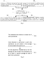
- Fig. 1 is a flowchart of a video bit rate control method of the present invention.
- the video bit rate control method of the present invention is used for controlling the bit rate of video bit streams within a periodical time interval, including the following steps.
- a user pre-sets the first bit rate value, and according to the first bit rate value and the code size generated in the previous period of time, generates the first quantization parameter and outputs it in real time.
- the first bit rate value is a predetermined target average bit rate, which is a fixed value in each periodical time interval.
- the target average bit rate is the average bit rate that coding bit streams reach after a long-time adjustment, namely the average bit rate after long-time statistics; the target average bit rate can be regarded as a fixed value in each periodical time interval.
- the target average bit rate is decided by a video storage period and storage capacity.
- the user pre-sets the second bit rate value, and according to the second bit rate value and the code size generated in the previous period of time (corresponding to the previous period of time in S1), generates the second quantization parameter and outputs it in real time.
- the second bit rate value is a predetermined upper limit value of bit rate.
- the upper limit value of bit rate is the upper limit bit rate of instantaneous statistics of the coding bit streams.
- the upper limit value of bit rate corresponds to the bit rate under the limit of user transmission bandwidth.
- sequence of performing S1 and S2 is not exclusive, they can be performed successively or simultaneously.
- the first quantization parameter is composed with the second quantization parameter, so as to select the bigger one to code the image frame in a current period of time.
- the image frame not quantized is the one not coded by using the quantization parameter.
- the bigger quantization parameter is selected to code the image frame not quantized in the current period of time. If the first quantization parameter is greater than or equal to the second quantization parameter, the first quantization parameter is used to code the image frame; or else, the second quantization parameter is used to code the image frame.
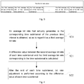
- Fig. 2 is a flowchart of performing bit rate control to a first bit rate value in an embodiment of the present invention.
- the step of according to the pre-set first bit rate value and the code size generated in the previous period of time, generating the first quantization parameter further includes the following steps: S10: the periodical time interval is divided into N time subintervals, wherein N is greater than 1.
- the current time interval corresponding to the first bit rate value is first divided into at least two time subintervals. Supposing, the current time interval corresponding to the first bit rate value is 24 hours, the 24 hours can be divided into six time subintervals or eight time subintervals, and so on, referring to Fig. 3; Fig. 3 is a reference diagram of dividing a periodical time interval in the present invention.
- the periodical time interval is a natural periodical time interval, such as one day and one week.
- initial allocation is performed to each time subinterval (namely N time subintervals), so as to obtain the first average bit rate of each time subinterval, namely the first average bit rates of N time subintervals: the first average bit rate of the first time subinterval, the first average bit rate of the second time subinterval, ..., the first average bit rate of the Nth time subinterval, and make the first average bit rate of the N time subintervals satisfy the above formula; that is, a result obtained by dividing the sum of the first average bit rates of all the time subintervals by N is required to be equal to the first bit rate value.
- bit rate adjustment is performed to the first average bit rate of each time subinterval (namely the first average bit rate of N time subintervals), so as to obtain the second average bit rate of each time subinterval, namely the second average bit rates of N time subintervals: the second average bit rate of the first time subinterval, the second average bit rate of the second time subinterval, ..., the second average bit rate of the Nth time subinterval, and make the second average bit rate of the N time subintervals satisfy the above formula; that is, a result obtained by dividing the sum of the second average bit rates of all the time subintervals after adjustment by N is required to be equal to the first bit rate value too.
- the step of performing initial allocation to each time subinterval includes that: according to pre-set prior information, initial allocation is performed to each time subinterval; or the first average bit rate of each time subinterval is allocated to be the same as the first bit rate value.
- a bit rate allocation method adopts different bit rate allocation modes because of the different phases.
- the initial allocation includes that: according to the pre-set prior information, initial allocation is performed to each time subinterval; or the first average bit rate of each time subinterval is allocated to be the same as the first bit rate value.
- the first bit rate value is 48kbps
- the periodical time interval corresponding to the first bit rate value is 24 hours. If the 24 hours are divided into six time intervals, then initial allocation is performed to the six time intervals; if initial allocation is performed according to the pre-set prior information, then the first average bit rate of the first time subinterval, ..., the first average bit rate of the sixth time subinterval may be 6kbps, 10kbps, 13kbps, 9kbps, 7kbps and 3kbps, or 4 kbps, 8kbps, 12kbps, 12kbps, 8kbps and 4kbps.
- the second initial allocation mode that is, the first bit rate value 48kbps is equally allocated to six time subintervals, the first average bit rate of the first time subinterval, ..., the first average bit rate of the sixth time subinterval are respectively 8, ..., 8.
- the step of performing bit rate allocation to the first average bit rate of each time subinterval includes that: after the end of each time subinterval, bit rate allocation is performed according to the difference value of each time subinterval; and/or after the end of all the N time subintervals, bit rate adjustment is performed according to the difference values of all the time subintervals.
- bit rate allocation is performed according to the difference value of each time subinterval
- bit rate adjustment is performed according to the difference values of all the time subintervals.
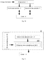
- Fig. 4 is a flowchart of performing bit rate allocation according to a difference value of each time interval in an optional embodiment of the present invention.
- the step of performing bit rate allocation according to the difference value of each time interval further includes the following steps.
- bit rate allocation is performed to the first average bit rate after the end of the first time subinterval of the current time interval
- the average bit rate that actually generates in the first time subinterval of the previous time interval is obtained, so as to regard it as the third average bit rate.
- the difference value between the second average bit rate of the first time subinterval and the average bit rate that actually generates in the first time subinterval of the previous time interval is calculated.
- bit rate adjustment is performed according to the difference value of each time subinterval.
- bit rate adjustment is performed according to the calculated difference value
- the difference values of all the time subintervals are calculated in turn, and bit rate adjustment is performed.
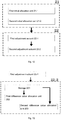
- Fig. 5 is a flowchart of after the end of each time interval, performing bit rate adjustment according to a difference value of each time interval in an embodiment of the present invention.
- the step of performing bit rate adjustment according to the difference value of each time interval after the end of each time interval further includes the following steps.
- the difference value generated in the first time subinterval is 1 kbps
- the difference value 1 kbps of the first time subinterval is divided by 6 (continuing from the above example, supposing N is 6)
- the first average difference value is obtained, namely 1/6. If the difference value generated in the second time subinterval is -1 kbps, then obtained first average difference value is -1/6.
- S31 the first average difference value is overlaid on the second average bit rate of each time subinterval in the N time subintervals after the time subinterval.
- the first average difference value (namely 1/6) is overlaid on the second average bit rate of each time subinterval in the N time subintervals (from the second time subinterval to the (N+1)th time subinterval) after the first time subinterval.
- the first average difference value (namely -1/6) of the second time subinterval is overlaid on the second average bit rate of each time subinterval in the N time subintervals (from the third time subinterval to the (N+2)th time subinterval) after the second time subinterval. If the difference value generated in the third time subinterval is 0kbps, there is no need to allocate the difference value.
- overlaying the first average difference value on the second average bit rate of each time subinterval in the N time subintervals after the time subinterval aims to even the influence of the difference value to one day to digest.
- Fig. 6 is a flowchart of performing bit rate adjustment according to difference values of all time intervals in another optional embodiment of the present invention.
- the step of performing bit rate adjustment according to the difference values of all the time subintervals further includes the following steps.
- the difference value between the second average bit rate of the N time subintervals and the average bit rate that actually generates in the corresponding time subinterval is calculated, and for each positive difference value time subinterval when the difference value is positive, at least a part of the difference value is put into the saving pool.
- At least a part can be 1/2 or 2/5, or other values, the most is all of the difference value.
- the total bit rate value of the saving pool is allocated to each negative difference value time subinterval in the current time interval.
- Fig. 7 is a flowchart of putting a difference value in a saving pool in an embodiment of the present invention.
- the step of putting at least a part of the difference value into the saving pool further includes the following steps.
- the second average bit rate of the positive difference value time subinterval is reallocated, so as to reduce the second average bit rate of positive difference value time subinterval by at least a part of the difference value.
- the second average bit rates of all the time subintervals are reallocated, namely at least a part of the difference value is reduced based on the second average bit rates of all the time subintervals.
- the current value of the saving pool (namely the current bit rate value of the saving pool) is increased by at least a part of the difference value.
- the step of allocating the total bit rate value of the saving pool to each negative difference value time subinterval includes that: the total bit rate value of the saving pool is equally allocated to each negative difference value time subinterval; or according to a difference value ratio, the total bit rate value of the saving pool is allocated to each negative difference value time subinterval.
- Fig. 8 is a flowchart of equally allocating the total bit rate value of the saving pool in an optional embodiment of the present invention.
- the step of equally allocating the total bit rate value of the saving pool to each negative difference value time subinterval further includes the following steps:
- Fig. 9 is a flowchart of allocating the total bit rate value of the saving pool according to a difference value ratio in another optional embodiment of the present invention.
- the step of allocating the total bit rate value of the saving pool to each negative difference value time subinterval according to the difference value ratio further includes the following steps.
- S70 the difference value ratio of the difference value of each negative difference value time subinterval to the total difference value of all the negative difference value time subintervals is calculated.
- each saved bit rate allocation value is respectively overlaid on the second average bit rate of its corresponding time subinterval.
- the meaning of allocating according to the difference value ratio is that: if the difference value ratios of A, B and C are 1/6, 2/6 and 3/6, the total bit rate value 6 is multiplied by the above three ratios respectively to obtain the saved bit rate allocation values 1, 2 and 3 of each time subinterval, and 1, 2 and 3 are overlaid on -1, -2 and -3 respectively.
- the method before the step of calculating the second quantization parameter, the method further includes that: when a transmission bandwidth constraint is not detected, performing the step of coding the image frame by using the second quantization parameter is stopped.
- the transmission bandwidth is limited; if it is not detected that the transmission bandwidth is limited, it means the transmission bandwidth is not limited, then performing the step of coding the image frame by using the second quantization parameter is stopped, and the image frame is coded by only using the first quantization parameter. If the transmission bandwidth constraint is detected, it means the transmission bandwidth is limited, then both the step of coding the image frame by using the first quantization parameter and the step of coding the image frame by using the second quantization parameter are performed.
- the video bit rate control method of the present invention is elaborated; a long time (like 24 hours) is divided, initial allocation is performed to the first bit rate value (namely the target average bit rate) to obtain the first average bit rate, and bit rate adjustment is performed to the first average bit rate to obtain the second average bit rate, wherein the bit rate of each time subinterval reflects the scenario complexity of the time subinterval, so that the stability of video quality can be guaranteed to the greatest extent while the bit rate (namely the second average bit rate) of each time subinterval is approximate to the first bit rate value (namely the target average bit rate).
- the video bit rate control method based on the storage capacity (the bit rate control method based on the target average bit rate) and based on the transmission bandwidth (the bit rate control method based on the upper limit of bit rate) solves the problem that the existing CBR control method and the VBR control method can only select one bit rate for control, and combines them together.
- Fig. 10 is a structure diagram of a video bit rate control device of the present invention.
- the video bit rate control device of the present invention is used for controlling the bit rate of video bit streams within a periodical time interval, including: an image sensor1, a first bit rate controller 2, a second bit rate controller 3, and a coder 4.
- the image sensor 1 is configured to obtain image information and generate video bit streams, and output the video bit streams to the first bit rate controller and the second bit rate controller.
- the first bit rate controller 2 is connected to the image sensor 1, and configured to generate the first quantization parameter according to the pre-set first bit rate value, and output the first quantization parameter to the coder.
- the second bit rate controller 3 is connected to the image sensor 1, and configured to generate the second quantization parameter according to the pre-set second bit rate value, and output the second quantization parameter to the coder.
- the coder 4 is connected to the first bit rate controller 2 and the second bit rate controller 3, and configured to code the image frame of the current period of time according to the greater one in the first quantization parameter and the second quantization parameter.
- the first bit rate controller 2 is further configured to receive from the coder 4 the code size generated in the previous period of time, and calculate according to the first bit rate value and the code size of the previous period of time to obtain the first quantization parameter
- the second bit rate controller 3 is further configured to receive from the coder 4 the code size generated in the previous period of time, and calculate according to the second bit rate value and the code size of the previous period of time to obtain the second quantization parameter.
- Fig. 11 is a structure diagram of a first bit rate controller of the present invention.
- the first bit rate controller 2 divides the periodical time interval into N time subintervals, wherein N is greater than 1; the device further includes: an initial bit rate allocation unit 21 and a bit rate adjustment unit 22.
- the first bit rate controller 2 further includes a bit rate obtaining unit 23, which is connected to the bit rate adjustment unit 22, and configured to obtain an average bit rate that actually generates in the corresponding time subinterval of the previous time interval, so as to regard it as a third average bit rate;
- the bit rate adjustment unit 22 further includes a difference value calculating unit 22-3, which is connected to the bit rate obtaining unit 23, and configured to calculate a difference value between the second average bit rate of each time subinterval and the third average bit rate corresponding to the time subinterval.
- Fig. 12 is a structure diagram of an initial bit rate allocation unit and a bit rate adjustment unit of the present invention.
- the initial bit rate allocation unit 21 includes a first initial allocation unit 21-1 and/or a second initial allocation unit 21-2.
- the first initial allocation unit 21-1 is configured to perform initial allocation to the average bit rate of each time subinterval according to the pre-set prior information.
- the second initial allocation unit 21-2 is configured to allocate the first average bit rate of each time subinterval to be the same as the first bit rate value.
- the bit rate adjustment unit 22 includes: a first adjustment subunit 22-1 and/or a second adjustment subunit 22-2.
- the first adjustment subunit 22-1 is configured to, after the end of each time subinterval, perform bit rate allocation according to the difference value of each time subinterval.
- the first adjustment subunit 22-1 performs bit rate allocation in the following way: dividing the difference value of the current time subinterval by N to obtain the first average difference value; and overlaying the first average difference value on the second average bit rate of each time subinterval in the N time subintervals after the time subinterval.
- the second adjustment subunit 22-2 is configured to, after the end of all the N time subintervals, perform bit rate allocation according to the difference values of all the time subintervals.
- Fig. 13 is a structure diagram of a second adjustment subunit of the present invention.
- the second adjustment subunit 22-2 further includes a storage 201 and a first difference value allocation unit 202.
- the storage 201 is configured to store the saved bit rate value.
- the first difference value allocation unit 202 is connected to the difference value calculating unit 22-3 and the storage 201, and configured to, for each positive difference value time subinterval when the difference value is positive, store at least a part of the difference value into the storage 201.
- the second adjustment subunit 22-2 is configured to, for each negative difference value time subinterval when the difference value is negative, allocate the total saved bit rate value of the storage 201 to each negative difference value time subinterval.
- the second adjustment subunit 22-2 reallocates the second average bit rate of the positive difference value time subinterval, so as to reduce the second average bit rate of positive difference value time subinterval by at least a part of the difference value; and the first difference value allocation unit 202 increases the current value of the storage 201 by at least a part of the difference value.
- the second adjustment subunit 22-2 allocates the total saved bit rate value in the storage 201 to each negative difference value time subinterval in the following way: dividing the total bit rate value of the saving pool by the number of the each negative difference value time subintervals, so as to obtain the second average difference value; and overlaying the second average difference value on the second average bit rate of each negative difference value time subinterval.
- the second adjustment subunit 22-2 further includes: a second difference value allocation unit 203, configured to calculate the difference value ratio of the difference value of each negative difference value time subinterval to the total difference value of all the negative difference value time subintervals, and multiply the total saved bit rate value in the storage 201 by the difference value ratio of each negative difference value time subinterval, so as to obtain the saved bit rate allocation value of each negative difference value time subinterval; and the second adjustment subunit 22-2 respectively overlays each saved bit rate allocation value on the second average bit rate of its corresponding time subinterval.
- a second difference value allocation unit 203 configured to calculate the difference value ratio of the difference value of each negative difference value time subinterval to the total difference value of all the negative difference value time subintervals, and multiply the total saved bit rate value in the storage 201 by the difference value ratio of each negative difference value time subinterval, so as to obtain the saved bit rate allocation value of each negative difference value time subinterval; and the second adjustment subunit 22-2 respectively overlays each saved bit rate allocation value on the second average
- the first bit rate value is the predetermined target average bit rate, which is a fixed value in each periodical time interval; and the second bit rate value is the predetermined upper limit value of bit rate.
- the device further includes a bandwidth detecting unit 6, which is configured to, when the transmission bandwidth constraint is not detected, stop the coder 4 from coding by using the second quantization parameter.
- the video bit rate control method of the present invention is elaborated; a long time (like 24 hours) is divided, initial allocation is performed to the first bit rate value (namely the target average bit rate) to obtain the first average bit rate, and bit rate adjustment is performed to the first average bit rate to obtain the second average bit rate, wherein the bit rate of each time subinterval reflects the scenario complexity of the time subinterval, so that the stability of video quality can be guaranteed to the greatest extent while the bit rate (namely the second average bit rate) of each time subinterval is approximate to the first bit rate value (namely the target average bit rate).
- the video bit rate control method based on the storage capacity (the bit rate control method based on the target average bit rate) and based on the transmission bandwidth (the bit rate control method based on the upper limit of bit rate) solves the problem that the existing CBR control method and the VBR control method can only select one bit rate for control, and combines them together.
- the present invention provides a bit rate control method and a video coding device.
- the technical solution of the present invention can realize long-time (for example, 24 hours) control of target average bit rate, and can guarantee the stability of video quality to the greatest extent.
Landscapes
- Engineering & Computer Science (AREA)
- Multimedia (AREA)
- Signal Processing (AREA)
- Compression Or Coding Systems Of Tv Signals (AREA)
Abstract
Description
- The present invention belongs to the field of video compression technology, and in particular to a video bit rate control method and a video coding device.
- The output bit rate of video coding is tied to image contents, coding modes, quantization parameters, and so on. Generally, the output bit rate of video coding constantly changes. Transmission bandwidth and storage capacity are known, but the output bit rate of video coding constantly changes, so the contradiction requires bit rate control for regulation.
- There are generally two bit rate control methods: a Constant Bit Rate (CBR) control method and a Variable Bit Rate (VBR) control method. The CBR serves the stability of bit rate, and the VBR serves the stability of bit rate quality. When the above two bit rate control methods set the bit rate,
- 1. the CBR is usually used for setting an average value of the bit rate; and
- 2. the VBR is usually used for setting an upper limit value of the bit rate.
- In the practical application process, both the two bit rate methods have some problems.
- 1. When the average value of the bit rate is set using the CBR, from long time, different time intervals have different requirements on the bit rate. For example, generally the requirement on the bit rate during the day is higher than that at night; at this time, setting the average bit rate value high will cause wastes, but setting it low will influence the video quality of some time intervals.
- 2. When the upper limit value of the bit rate is set using the VBR, the VBR control method does not cause the waste of bit rate while guaranteeing the overall video quality. However, the specific storage capacity cannot be previously estimated; when a storage space is configured, it is always configured according to the upper limit value of bit rate, which increases the cost.
- The actual transmission bandwidth and storage capacity are limited, but both the existing two bit rate control methods and a bit rate setting method cannot balance the relation between the video quality and the target bit rate.
- The present invention is intended to provide a video bit rate control method and a video coding device, which can realize long-time (for example, 24 hours) bit rate control, and can guarantee the stability of video quality to the greatest extent.
- To this end, an aspect of the present invention provides a video bit rate control method for controlling the bit rate of video bit streams within a periodical time interval, which includes the following steps: according to a pre-set first bit rate value and a code size generated in a previous period of time, a first quantization parameter is generated; according to a pre-set second bit rate value and the code size generated in the previous period of time, a second quantization parameter is generated; the first quantization parameter is composed with the second quantization parameter; if the first quantization parameter is greater than or equal to the second quantization parameter, an image frame in a current period of time is coded by using the first quantization parameter; and if the first quantization parameter is less than the second quantization parameter, the image frame in the current period of time is coded by using the second quantization parameter.
- The step of according to the pre-set first bit rate value and the code size generated in the previous period of time, generating the first quantization parameter includes that: the periodical time interval is divided into N time subintervals, wherein N is greater than 1; initial allocation is performed to each time subinterval, so as to obtain a first average bit rate of each time subinterval, and make the first average bit rate satisfy the following formula:


- According to the pre-set first bit rate value and the code size generated in the previous period of time, the first quantization parameter is generated.
- The step of performing initial allocation includes that: according to pre-set prior information, initial allocation is performed to the average bit rate of each time subinterval; or the first average bit rate of each time subinterval is allocated to be the same as the first bit rate value.
- The step of performing bit rate adjustment includes that: an average bit rate that actually generates in the corresponding time subinterval of the previous time interval is obtained, so as to regard it as a third average bit rate; a difference value between the second average bit rate of each time subinterval and the third average bit rate corresponding to the time subinterval is calculated; after the end of each time subinterval, bit rate adjustment is performed according to the difference value of each time subinterval; and/or after the end of all the N time subintervals, bit rate adjustment is performed according to the difference values of all the time subintervals.
- The step of performing bit rate adjustment according to the difference value of each time subinterval after the end of each time subinterval includes that: the difference value of the current time subinterval is divided by N to obtain a first average difference value; and the first average difference value is overlaid on the second average bit rate of each time subinterval in the N time subintervals after the time subinterval.
- The step of performing bit rate allocation according to the difference values of all the time subintervals after the end of all the N time subintervals includes that: for each positive difference value time subinterval when the difference value is positive, at least a part of the difference value is put into a saving pool; and for each negative difference value time subinterval when the difference value is negative, the total bit rate value of the saving pool is allocated to each negative difference value time subinterval.
- The step of putting at least a part of the difference value into the saving pool includes that: the second average bit rate of the positive difference value time subinterval is reallocated, so as to reduce the second average bit rate of positive difference value time subinterval by at least a part of the difference value; and the current value of the saving pool is increased by at least a part of the difference value.
- The step of allocating the total bit rate value of the saving pool to each negative difference value time subinterval includes that: the total bit rate value of the saving pool is equally allocated to each negative difference value time subinterval; or according to a difference value ratio, the total bit rate value of the saving pool is allocated to each negative difference value time subinterval.
- The step of equally allocating the total bit rate value of the saving pool to each negative difference value time subinterval includes that: the total bit rate value of the saving pool is divided by the number of the negative difference value time subintervals, so as to obtain a second average difference value; and the second average difference value is overlaid on the second average bit rate of each negative difference value time subinterval.
- The step of allocating the total bit rate value of the saving pool to each negative difference value time subinterval according to the difference value ratio includes that: the difference value ratio of the difference value of each negative difference value time subinterval to the total difference value of all the negative difference value time subintervals is calculated; the total bit rate value of the saving pool is multiplied by the difference value ratio of each negative difference value time subinterval, so as to obtain a saved bit rate allocation value of each negative difference value time subinterval; and each saved bit rate allocation value is respectively overlaid on the second average bit rate of its corresponding time subinterval.
- The first bit rate value is a predetermined target average bit rate, which is a fixed value in each periodical time interval; and the second bit rate value is a predetermined upper limit value of bit rate. Before the step of calculating the second quantization parameter, the method further includes that: when a transmission bandwidth constraint is not detected, performing the step of coding the image frame by using the second quantization parameter is stopped.
- Another aspect of the present invention provides a video coding device for controlling the bit rate of video bit streams within a periodical time interval to perform video coding; the device includes: an image sensor, configured to obtain image information and generate video bit streams, and output the video bit streams to a first bit rate controller and a second bit rate controller; the first bit rate controller, configured to generate the first quantization parameter according to the pre-set first bit rate value, and output the first quantization parameter to an coder; the second bit rate controller, configured to generate the second quantization parameter according to the pre-set second bit rate value, and output the second quantization parameter to the coder; and the coder, configured to code the image frame of the current period of time according to the greater one in the first quantization parameter and the second quantization parameter.
- The first bit rate controller is further configured to receive from the coder the code size generated in the previous period of time, and calculate according to the first bit rate value and the code size of the previous period of time to obtain the first quantization parameter; and the second bit rate controller is further configured to receive from the coder the code size generated in the previous period of time, and calculate according to the second bit rate value and the code size of the previous period of time to obtain the second quantization parameter.
- The first bit rate controller divides the periodical time interval into N time subintervals, wherein N is greater than 1; the device further includes: an initial bit rate allocation unit, configured to perform initial allocation to each time subinterval, so as to obtain the first average bit rate of each time subinterval, and make the first average bit rate satisfy the following formula:

a bit rate adjustment unit (22), configured to perform bit rate adjustment to the first average bit rate of each time subinterval, so as to obtain the second average bit rate of each time subinterval, and make the second average bit rate satisfy the following formula:
- The initial bit rate allocation unit includes: a first initial allocation unit, configured to perform initial allocation to the average bit rate of each time subinterval according to the pre-set prior information; and/or a second initial allocation unit, configured to allocate the first average bit rate of each time subinterval to be the same as the first bit rate value.
- The first bit rate controller further includes a bit rate obtaining unit, configured to obtain the average bit rate that actually generates in the corresponding time subinterval of the previous time interval, so as to regard it as the third average bit rate;
the bit rate adjustment unit further includes a difference value calculating unit, configured to calculate the difference value between the second average bit rate of each time subinterval and the third average bit rate corresponding to the time subinterval. - The bit rate adjustment unit includes: a first adjustment subunit, which is configured to, after the end of each time subinterval, perform bit rate allocation according to the difference value of each time subinterval; and/or a second adjustment subunit, which is configured to, after the end of all the N time subintervals, perform bit rate allocation according to the difference values of all the time subintervals.
- The first adjustment subunit performs bit rate allocation in the following way: dividing the difference value of the current time subinterval by N to obtain the first average difference value; and overlaying the first average difference value on the second average bit rate of each time subinterval in the N time subintervals after the time subinterval.
- The second adjustment subunit further includes: a storage, configured to store the saved bit rate value; a first difference value allocation unit, which is configured to, for each positive difference value time subinterval when the difference value is positive, store at least a part of the difference value into the storage; and the second adjustment subunit, which is configured to, for each negative difference value time subinterval when the difference value is negative, allocate the total saved bit rate value of the storage to each negative difference value time subinterval.
- The second adjustment subunit reallocates the second average bit rate of the positive difference value time subinterval, so as to reduce the second average bit rate of positive difference value time subinterval by at least a part of the difference value; and the first difference value allocation unit increases the current value of the storage by at least a part of the difference value.
- The second adjustment subunit allocates the total saved bit rate value in the storage to each negative difference value time subinterval in the following way: dividing the total bit rate value of the saving pool by the number of the each negative difference value time subintervals, so as to obtain the second average difference value; and overlaying the second average difference value on the second average bit rate of each negative difference value time subinterval.
- The second adjustment subunit further includes a second difference value allocation unit, configured to calculate the difference value ratio of the difference value of each negative difference value time subinterval to the total difference value of all the negative difference value time subintervals, and multiply the total saved bit rate value in the storage by the difference value ratio of each negative difference value time subinterval, so as to obtain the saved bit rate allocation value of each negative difference value time subinterval; and the second adjustment subunit respectively overlays each saved bit rate allocation value on the second average bit rate of its corresponding time subinterval.
- The first bit rate value is the predetermined target average bit rate, which is a fixed value in each periodical time interval; and the second bit rate value is the predetermined upper limit value of bit rate.
- The device further includes a bandwidth detecting unit, which is configured to, when the transmission bandwidth constraint is not detected, stop the coder from coding by using the second quantization parameter.
- As mentioned above, the video bit rate control method can realize long-time (for example, 24 hours) bit rate control, and can guarantee the stability of video quality to the greatest extent.
-
-
Fig. 1 is a flowchart of a video bit rate control method of the present invention; -
Fig. 2 is a flowchart of performing bit rate control to a first bit rate value in an embodiment of the present invention; -
Fig. 3 is a reference diagram of dividing a periodical time interval in the present invention; -
Fig. 4 is a flowchart of performing bit rate allocation according to a difference value of each time interval in an optional embodiment of the present invention; -
Fig. 5 is a flowchart of after the end of each time interval, performing bit rate adjustment according to a difference value of each time interval in an embodiment of the present invention; -
Fig. 6 is a flowchart of performing bit rate adjustment according to difference values of all time intervals in another optional embodiment of the present invention; -
Fig. 7 is a flowchart of putting a difference value in a saving pool in an embodiment of the present invention; -
Fig. 8 is a flowchart of equally allocating the total bit rate value of the saving pool in an optional embodiment of the present invention; -
Fig. 9 is a flowchart of allocating the total bit rate value of the saving pool according to a difference value ratio in another optional embodiment of the present invention; -
Fig. 10 is a structure diagram of a video bit rate control device of the present invention; -
Fig. 11 is a structure diagram of a first bit rate controller of the present invention; -
Fig. 12 is a structure diagram of an initial bit rate allocation unit and a bit rate adjustment unit of the present invention; and -
Fig. 13 is a structure diagram of a second adjustment subunit of the present invention. - For making the aim, the technical solutions and the advantages of the present invention more clear, the present invention is further elaborated below in combination with the accompanying drawings and specific embodiments. It should be understood that these descriptions are only exemplarily and not intended to limit the scope of the present invention. In addition, the description of the known structure and technology is omitted in the following elaboration, so as to avoid unnecessary confusion of the concept of the present invention.
- Note that, the CBR is a term for describing the quality of communication service, which means a video coding bit stream is always approximate to a target bit rate in a coding process. For video coding, CBR coding means that an output bit rate per second of a coder (or an input bit rate of a decoder) should be a fixed value (constant). Generally, the coder detects the complexity of each frame, and then calculates the bit rate. If the bit rate is too low, then useless data is filled to make the bit rate consistent with a specified bit rate; if the bit rate is too high, then the bit rate is lowered appropriately to make it consistent with the specified bit rate. So, the coding efficiency of CBR mode is low. There are more picture details in a fast moving picture, and more bits are usually required for description, but a coding method adopting CBR lowers the bit rate forcibly during coding, which causes the loss of detail information of part of the picture, so the picture of video is fuzzy and not clear. For audio compression, like MP3, the bit rate is used for showing how many bits are occupied by audio data of each second, the higher the value of the bit rate, the better the sound quality.
- Whether for audio coding or video coding, the advantage of the CBR is fast compression and being capable of being supported by most software and devices; especially when multimedia communication is performed in a channel with limited bandwidth, the coding mode adopting CBR is very beneficial, because it is the highest bit rate limited at this time, the CBR can use such a channel better. However, the CBR is not suitable for storing, because the CBR cannot provide enough bit rates to code complex video contents, which causes the deterioration of quality; besides, the CBR wastes some bit rates when simple video contents are coded.
- The VBR is another term for describing the quality of communication service; the VBR can change with the different complexities of video images in the coding process, so its coding efficiency is high. VBR coding means that the output bit rate of the coder (or the input bit rate of the decoder) can adjust adaptively according to the complexity of an input signal of the coder, so as to keep the output quality, but not the output bit rate, remaining unchanged. The VBR is suitable for storage, and it can use the limited storage space better, that is, more code words are used for coding a segment with high complexity, and fewer code words are used for coding a segment with low complexity.
-
Fig. 1 is a flowchart of a video bit rate control method of the present invention. - As shown in
Fig. 1 , the video bit rate control method of the present invention is used for controlling the bit rate of video bit streams within a periodical time interval, including the following steps. - S1: according to a pre-set first bit rate value and a code size generated in a previous period of time, a first quantization parameter is generated.
- In the step, a user pre-sets the first bit rate value, and according to the first bit rate value and the code size generated in the previous period of time, generates the first quantization parameter and outputs it in real time.
- In the present invention, the first bit rate value is a predetermined target average bit rate, which is a fixed value in each periodical time interval. Specifically, the target average bit rate is the average bit rate that coding bit streams reach after a long-time adjustment, namely the average bit rate after long-time statistics; the target average bit rate can be regarded as a fixed value in each periodical time interval. The target average bit rate is decided by a video storage period and storage capacity.
- S2: according to a pre-set second bit rate value and the code size generated in the previous period of time, a second quantization parameter is generated.
- In the step, the user pre-sets the second bit rate value, and according to the second bit rate value and the code size generated in the previous period of time (corresponding to the previous period of time in S1), generates the second quantization parameter and outputs it in real time.
- In the present invention, the second bit rate value is a predetermined upper limit value of bit rate. The upper limit value of bit rate is the upper limit bit rate of instantaneous statistics of the coding bit streams. The upper limit value of bit rate corresponds to the bit rate under the limit of user transmission bandwidth.
- Here, the sequence of performing S1 and S2 is not exclusive, they can be performed successively or simultaneously.
- S3: the first quantization parameter is composed with the second quantization parameter.
- In the step, the first quantization parameter is composed with the second quantization parameter, so as to select the bigger one to code the image frame in a current period of time.
- In the present invention, the image frame not quantized is the one not coded by using the quantization parameter.
- S4: if the first quantization parameter is greater than or equal to the second quantization parameter, the image frame is coded by using the first quantization parameter.
- S5: if the first quantization parameter is less than the second quantization parameter, the image frame in the current period of time is coded by using the second quantization parameter.
- Specifically, according to the comparison result, the bigger quantization parameter is selected to code the image frame not quantized in the current period of time. If the first quantization parameter is greater than or equal to the second quantization parameter, the first quantization parameter is used to code the image frame; or else, the second quantization parameter is used to code the image frame.
-
Fig. 2 is a flowchart of performing bit rate control to a first bit rate value in an embodiment of the present invention. - As shown in
Fig. 2 , in an embodiment, the step of according to the pre-set first bit rate value and the code size generated in the previous period of time, generating the first quantization parameter further includes the following steps:
S10: the periodical time interval is divided into N time subintervals, wherein N is greater than 1. - In the step, before controlling the bit rate of the first bit rate value, the current time interval corresponding to the first bit rate value is first divided into at least two time subintervals. Supposing, the current time interval corresponding to the first bit rate value is 24 hours, the 24 hours can be divided into six time subintervals or eight time subintervals, and so on, referring to
Fig. 3; Fig. 3 is a reference diagram of dividing a periodical time interval in the present invention. - In the present invention, the periodical time interval is a natural periodical time interval, such as one day and one week.
- S11: initial allocation is performed to each time subinterval, so as to obtain a first average bit rate of each time subinterval, and make the first average bit rate satisfy the following formula:

- In the step, initial allocation is performed to each time subinterval (namely N time subintervals), so as to obtain the first average bit rate of each time subinterval, namely the first average bit rates of N time subintervals: the first average bit rate of the first time subinterval, the first average bit rate of the second time subinterval, ..., the first average bit rate of the Nth time subinterval, and make the first average bit rate of the N time subintervals satisfy the above formula; that is, a result obtained by dividing the sum of the first average bit rates of all the time subintervals by N is required to be equal to the first bit rate value.
- S12: bit rate adjustment is performed to the first average bit rate of each time subinterval, so as to obtain a second average bit rate of each time subinterval, and make the second average bit rate satisfy the following formula:

- In the step, bit rate adjustment is performed to the first average bit rate of each time subinterval (namely the first average bit rate of N time subintervals), so as to obtain the second average bit rate of each time subinterval, namely the second average bit rates of N time subintervals: the second average bit rate of the first time subinterval, the second average bit rate of the second time subinterval, ..., the second average bit rate of the Nth time subinterval, and make the second average bit rate of the N time subintervals satisfy the above formula; that is, a result obtained by dividing the sum of the second average bit rates of all the time subintervals after adjustment by N is required to be equal to the first bit rate value too.
- In the present invention, the step of performing initial allocation to each time subinterval includes that: according to pre-set prior information, initial allocation is performed to each time subinterval; or the first average bit rate of each time subinterval is allocated to be the same as the first bit rate value. Specifically, a bit rate allocation method adopts different bit rate allocation modes because of the different phases. The initial allocation (namely initial bit rate allocation) includes that: according to the pre-set prior information, initial allocation is performed to each time subinterval; or the first average bit rate of each time subinterval is allocated to be the same as the first bit rate value.
- For example, it is supposed that the first bit rate value is 48kbps, and the periodical time interval corresponding to the first bit rate value is 24 hours. If the 24 hours are divided into six time intervals, then initial allocation is performed to the six time intervals; if initial allocation is performed according to the pre-set prior information, then the first average bit rate of the first time subinterval, ..., the first average bit rate of the sixth time subinterval may be 6kbps, 10kbps, 13kbps, 9kbps, 7kbps and 3kbps, or 4 kbps, 8kbps, 12kbps, 12kbps, 8kbps and 4kbps. If the second initial allocation mode is adopted, that is, the first bit rate value 48kbps is equally allocated to six time subintervals, the first average bit rate of the first time subinterval, ..., the first average bit rate of the sixth time subinterval are respectively 8, ..., 8.
- In the present invention, the step of performing bit rate allocation to the first average bit rate of each time subinterval includes that: after the end of each time subinterval, bit rate allocation is performed according to the difference value of each time subinterval; and/or after the end of all the N time subintervals, bit rate adjustment is performed according to the difference values of all the time subintervals. Specifically, optionally, it is feasible to only perform the step of performing bit rate allocation according to the difference value of each time subinterval, or only perform the step of performing bit rate allocation according to the difference values of all the time subintervals, or performing the two bit rate allocation methods at the same time.
-
Fig. 4 is a flowchart of performing bit rate allocation according to a difference value of each time interval in an optional embodiment of the present invention. - As shown in
Fig. 4 , in an optional embodiment, the step of performing bit rate allocation according to the difference value of each time interval further includes the following steps. - S20: an average bit rate that actually generates in the corresponding time subinterval of the previous time interval is obtained, so as to regard it as a third average bit rate.
- For example, when bit rate allocation is performed to the first average bit rate after the end of the first time subinterval of the current time interval, the average bit rate that actually generates in the first time subinterval of the previous time interval is obtained, so as to regard it as the third average bit rate.
- S21: a difference value between the second average bit rate of each time subinterval and the third average bit rate corresponding to the time subinterval is calculated.
- Continuing from the above example, the difference value between the second average bit rate of the first time subinterval and the average bit rate that actually generates in the first time subinterval of the previous time interval is calculated.
- S22: after the end of each time subinterval, bit rate adjustment is performed according to the difference value of each time subinterval.
- Continuing from the above example, after the end of the first time subinterval of the current time interval, bit rate adjustment is performed according to the calculated difference value, the difference values of all the time subintervals (N time subintervals) are calculated in turn, and bit rate adjustment is performed.
-
Fig. 5 is a flowchart of after the end of each time interval, performing bit rate adjustment according to a difference value of each time interval in an embodiment of the present invention. - As shown in
Fig. 5 , in an embodiment, the step of performing bit rate adjustment according to the difference value of each time interval after the end of each time interval further includes the following steps. - S30: the difference value of the current time subinterval is divided by N to obtain a first average difference value.
- Specifically, if the difference value generated in the first time subinterval is 1 kbps, the
difference value 1 kbps of the first time subinterval is divided by 6 (continuing from the above example, supposing N is 6), then the first average difference value is obtained, namely 1/6. If the difference value generated in the second time subinterval is -1 kbps, then obtained first average difference value is -1/6. - S31: the first average difference value is overlaid on the second average bit rate of each time subinterval in the N time subintervals after the time subinterval.
- Continuing from the above example, the first average difference value (namely 1/6) is overlaid on the second average bit rate of each time subinterval in the N time subintervals (from the second time subinterval to the (N+1)th time subinterval) after the first time subinterval. Likewise, the first average difference value (namely -1/6) of the second time subinterval is overlaid on the second average bit rate of each time subinterval in the N time subintervals (from the third time subinterval to the (N+2)th time subinterval) after the second time subinterval. If the difference value generated in the third time subinterval is 0kbps, there is no need to allocate the difference value.
- In the embodiment, overlaying the first average difference value on the second average bit rate of each time subinterval in the N time subintervals after the time subinterval aims to even the influence of the difference value to one day to digest.
-
Fig. 6 is a flowchart of performing bit rate adjustment according to difference values of all time intervals in another optional embodiment of the present invention. - As shown in
Fig. 6 , in an optional embodiment, the step of performing bit rate adjustment according to the difference values of all the time subintervals further includes the following steps. - S40: for each positive difference value time subinterval when the difference value is positive, at least a part of the difference value is put into a saving pool.
- In the step, after the end of all the N time subintervals, the difference value between the second average bit rate of the N time subintervals and the average bit rate that actually generates in the corresponding time subinterval is calculated, and for each positive difference value time subinterval when the difference value is positive, at least a part of the difference value is put into the saving pool.
- In the present invention, at least a part can be 1/2 or 2/5, or other values, the most is all of the difference value.
- S41: for each negative difference value time subinterval when the difference value is negative, the total bit rate value of the saving pool is allocated to each negative difference value time subinterval.
- In the step, for the negative difference value time subinterval when the difference value is negative, the total bit rate value of the saving pool is allocated to each negative difference value time subinterval in the current time interval.
-
Fig. 7 is a flowchart of putting a difference value in a saving pool in an embodiment of the present invention. - As shown in
Fig. 7 , in an embodiment, the step of putting at least a part of the difference value into the saving pool further includes the following steps. - S50: the second average bit rate of the positive difference value time subinterval is reallocated, so as to reduce the second average bit rate of positive difference value time subinterval by at least a part of the difference value.
- Specifically, the second average bit rates of all the time subintervals are reallocated, namely at least a part of the difference value is reduced based on the second average bit rates of all the time subintervals.
- S51: the current value of the saving pool is increased by at least a part of the difference value.
- Specifically, the current value of the saving pool (namely the current bit rate value of the saving pool) is increased by at least a part of the difference value.
- In the present invention, the step of allocating the total bit rate value of the saving pool to each negative difference value time subinterval includes that: the total bit rate value of the saving pool is equally allocated to each negative difference value time subinterval; or according to a difference value ratio, the total bit rate value of the saving pool is allocated to each negative difference value time subinterval.
-
Fig. 8 is a flowchart of equally allocating the total bit rate value of the saving pool in an optional embodiment of the present invention. - As shown in
Fig. 8 , in an optional embodiment, the step of equally allocating the total bit rate value of the saving pool to each negative difference value time subinterval further includes the following steps: - S60: the total bit rate value of the saving pool is divided by the number of the negative difference value time subintervals, so as to obtain a second average difference value.
- S61: the second average difference value is overlaid on the second average bit rate of each negative difference value time subinterval.
- Supposing the total bit rate value of the saving pool is 6, and the difference values of three negative difference value time subintervals A, B and C are -1, -2 and -3, the meaning of equally allocating is: 6 is divided by 3 to obtain the second average
bit rate value -
Fig. 9 is a flowchart of allocating the total bit rate value of the saving pool according to a difference value ratio in another optional embodiment of the present invention. - As shown in
Fig. 9 , the step of allocating the total bit rate value of the saving pool to each negative difference value time subinterval according to the difference value ratio further includes the following steps. - S70: the difference value ratio of the difference value of each negative difference value time subinterval to the total difference value of all the negative difference value time subintervals is calculated.
- S71: the total bit rate value of the saving pool is multiplied by the difference value ratio of each negative difference value time subinterval, so as to obtain a saved bit rate allocation value of each negative difference value time subinterval.
- S72: each saved bit rate allocation value is respectively overlaid on the second average bit rate of its corresponding time subinterval.
- Supposing the total bit rate value of the saving pool is 6, and the difference values of three negative difference value time subintervals A, B and C are -1, -2 and -3, the meaning of allocating according to the difference value ratio is that: if the difference value ratios of A, B and C are 1/6, 2/6 and 3/6, the total bit rate value 6 is multiplied by the above three ratios respectively to obtain the saved bit rate allocation values 1, 2 and 3 of each time subinterval, and 1, 2 and 3 are overlaid on -1, -2 and -3 respectively.
- In an optional embodiment, before the step of calculating the second quantization parameter, the method further includes that: when a transmission bandwidth constraint is not detected, performing the step of coding the image frame by using the second quantization parameter is stopped.
- Specifically, before calculating the second quantization parameter, first it is detected whether the transmission bandwidth is limited; if it is not detected that the transmission bandwidth is limited, it means the transmission bandwidth is not limited, then performing the step of coding the image frame by using the second quantization parameter is stopped, and the image frame is coded by only using the first quantization parameter. If the transmission bandwidth constraint is detected, it means the transmission bandwidth is limited, then both the step of coding the image frame by using the first quantization parameter and the step of coding the image frame by using the second quantization parameter are performed.
- As mentioned above, the video bit rate control method of the present invention is elaborated; a long time (like 24 hours) is divided, initial allocation is performed to the first bit rate value (namely the target average bit rate) to obtain the first average bit rate, and bit rate adjustment is performed to the first average bit rate to obtain the second average bit rate, wherein the bit rate of each time subinterval reflects the scenario complexity of the time subinterval, so that the stability of video quality can be guaranteed to the greatest extent while the bit rate (namely the second average bit rate) of each time subinterval is approximate to the first bit rate value (namely the target average bit rate). In addition, the video bit rate control method based on the storage capacity (the bit rate control method based on the target average bit rate) and based on the transmission bandwidth (the bit rate control method based on the upper limit of bit rate) solves the problem that the existing CBR control method and the VBR control method can only select one bit rate for control, and combines them together.
-
Fig. 10 is a structure diagram of a video bit rate control device of the present invention. - As shown in
Fig. 10 , the video bit rate control device of the present invention is used for controlling the bit rate of video bit streams within a periodical time interval, including: an image sensor1, a firstbit rate controller 2, a secondbit rate controller 3, and acoder 4. - The
image sensor 1 is configured to obtain image information and generate video bit streams, and output the video bit streams to the first bit rate controller and the second bit rate controller. - The first
bit rate controller 2 is connected to theimage sensor 1, and configured to generate the first quantization parameter according to the pre-set first bit rate value, and output the first quantization parameter to the coder. - The second
bit rate controller 3 is connected to theimage sensor 1, and configured to generate the second quantization parameter according to the pre-set second bit rate value, and output the second quantization parameter to the coder. - The
coder 4 is connected to the firstbit rate controller 2 and the secondbit rate controller 3, and configured to code the image frame of the current period of time according to the greater one in the first quantization parameter and the second quantization parameter. - In an embodiment, the first
bit rate controller 2 is further configured to receive from thecoder 4 the code size generated in the previous period of time, and calculate according to the first bit rate value and the code size of the previous period of time to obtain the first quantization parameter - The second
bit rate controller 3 is further configured to receive from thecoder 4 the code size generated in the previous period of time, and calculate according to the second bit rate value and the code size of the previous period of time to obtain the second quantization parameter. -
Fig. 11 is a structure diagram of a first bit rate controller of the present invention. - As shown in
Fig. 11 , the firstbit rate controller 2 divides the periodical time interval into N time subintervals, wherein N is greater than 1; the device further includes: an initial bitrate allocation unit 21 and a bitrate adjustment unit 22. - The initial bit
rate allocation unit 21 is configured to perform initial allocation to each time subinterval, so as to obtain the first average bit rate of each time subinterval, and make the first average bit rate satisfy the following formula:
- The bit
rate adjustment unit 22 is connected to the initial bitrate allocation unit 21, and configured to perform bit rate adjustment to the first average bit rate of each time subinterval, so as to obtain the second average bit rate of each time subinterval, and make the second average bit rate satisfy the following formula:
- In an embodiment, the first
bit rate controller 2 further includes a bitrate obtaining unit 23, which is connected to the bitrate adjustment unit 22, and configured to obtain an average bit rate that actually generates in the corresponding time subinterval of the previous time interval, so as to regard it as a third average bit rate;
the bitrate adjustment unit 22 further includes a difference value calculating unit 22-3, which is connected to the bitrate obtaining unit 23, and configured to calculate a difference value between the second average bit rate of each time subinterval and the third average bit rate corresponding to the time subinterval. -
Fig. 12 is a structure diagram of an initial bit rate allocation unit and a bit rate adjustment unit of the present invention. - As shown in
Fig. 12 , the initial bitrate allocation unit 21 includes a first initial allocation unit 21-1 and/or a second initial allocation unit 21-2. - The first initial allocation unit 21-1 is configured to perform initial allocation to the average bit rate of each time subinterval according to the pre-set prior information.
- The second initial allocation unit 21-2 is configured to allocate the first average bit rate of each time subinterval to be the same as the first bit rate value.
- As shown in
Fig. 12 , the bitrate adjustment unit 22 includes: a first adjustment subunit 22-1 and/or a second adjustment subunit 22-2. - The first adjustment subunit 22-1 is configured to, after the end of each time subinterval, perform bit rate allocation according to the difference value of each time subinterval.
- Specifically, the first adjustment subunit 22-1 performs bit rate allocation in the following way: dividing the difference value of the current time subinterval by N to obtain the first average difference value; and overlaying the first average difference value on the second average bit rate of each time subinterval in the N time subintervals after the time subinterval.
- The second adjustment subunit 22-2 is configured to, after the end of all the N time subintervals, perform bit rate allocation according to the difference values of all the time subintervals.
-
Fig. 13 is a structure diagram of a second adjustment subunit of the present invention. - As shown in
Fig. 13 , the second adjustment subunit 22-2 further includes astorage 201 and a first differencevalue allocation unit 202. - The
storage 201 is configured to store the saved bit rate value. - The first difference
value allocation unit 202 is connected to the difference value calculating unit 22-3 and thestorage 201, and configured to, for each positive difference value time subinterval when the difference value is positive, store at least a part of the difference value into thestorage 201. - The second adjustment subunit 22-2 is configured to, for each negative difference value time subinterval when the difference value is negative, allocate the total saved bit rate value of the
storage 201 to each negative difference value time subinterval. - Specifically, the second adjustment subunit 22-2 reallocates the second average bit rate of the positive difference value time subinterval, so as to reduce the second average bit rate of positive difference value time subinterval by at least a part of the difference value; and the first difference
value allocation unit 202 increases the current value of thestorage 201 by at least a part of the difference value. - Specifically, the second adjustment subunit 22-2 allocates the total saved bit rate value in the
storage 201 to each negative difference value time subinterval in the following way: dividing the total bit rate value of the saving pool by the number of the each negative difference value time subintervals, so as to obtain the second average difference value; and overlaying the second average difference value on the second average bit rate of each negative difference value time subinterval. - Specifically, the second adjustment subunit 22-2 further includes: a second difference
value allocation unit 203, configured to calculate the difference value ratio of the difference value of each negative difference value time subinterval to the total difference value of all the negative difference value time subintervals, and multiply the total saved bit rate value in thestorage 201 by the difference value ratio of each negative difference value time subinterval, so as to obtain the saved bit rate allocation value of each negative difference value time subinterval; and the second adjustment subunit 22-2 respectively overlays each saved bit rate allocation value on the second average bit rate of its corresponding time subinterval. - In the present invention, the first bit rate value is the predetermined target average bit rate, which is a fixed value in each periodical time interval; and the second bit rate value is the predetermined upper limit value of bit rate.
- In the present invention, the device further includes a bandwidth detecting unit 6, which is configured to, when the transmission bandwidth constraint is not detected, stop the
coder 4 from coding by using the second quantization parameter. - As mentioned above, the video bit rate control method of the present invention is elaborated; a long time (like 24 hours) is divided, initial allocation is performed to the first bit rate value (namely the target average bit rate) to obtain the first average bit rate, and bit rate adjustment is performed to the first average bit rate to obtain the second average bit rate, wherein the bit rate of each time subinterval reflects the scenario complexity of the time subinterval, so that the stability of video quality can be guaranteed to the greatest extent while the bit rate (namely the second average bit rate) of each time subinterval is approximate to the first bit rate value (namely the target average bit rate). In addition, the video bit rate control method based on the storage capacity (the bit rate control method based on the target average bit rate) and based on the transmission bandwidth (the bit rate control method based on the upper limit of bit rate) solves the problem that the existing CBR control method and the VBR control method can only select one bit rate for control, and combines them together.
- As mentioned above, the present invention provides a bit rate control method and a video coding device. The technical solution of the present invention can realize long-time (for example, 24 hours) control of target average bit rate, and can guarantee the stability of video quality to the greatest extent.
- It should be understood that the above specific embodiments are only used for exemplarily elaborating or illustrating the principle of the present invention, but not intended to limit the present invention. So, any modifications, equivalent replacements, improvements and the like within the spirit and scope of the present invention shall fall within the scope of protection of the present invention. In addition, the claims of the present invention are intended to cover all changes and modifications falling within the scope and border of the claims, or the equivalent form of the scope and border.
Claims (25)
- A video bit rate control method, for controlling the bit rate of video bit streams within a periodical time interval, comprising:according to a pre-set first bit rate value and a code size generated in a previous period of time, generating a first quantization parameter;according to a pre-set second bit rate value and the code size generated in the previous period of time, generating a second quantization parameter;comparing the first quantization parameter with the second quantization parameter;if the first quantization parameter is greater than or equal to the second quantization parameter, coding an image frame in a current period of time by using the first quantization parameter; andif the first quantization parameter is less than the second quantization parameter, coding the image frame in the current period of time by using the second quantization parameter.
- The method as claimed in claim 1, wherein according to the pre-set first bit rate value and the code size generated in the previous period of time, generating the first quantization parameter comprises:dividing the periodical time interval into N time subintervals, wherein N is greater than 1;performing initial allocation to each time subinterval, so as to obtain a first average bit rate of each time subinterval, and make the first average bit rate satisfy the following formula:


- The method as claimed in claim 2,wherein the step of performing initial allocation comprises:according to pre-set prior information, performing initial allocation to the average bit rate of each time subinterval; orallocating the first average bit rate of each time subinterval to be the same as the first bit rate value.
- The method as claimed in claim 2, wherein the step of performing bit rate adjustment comprises:obtaining an average bit rate that actually generates in the corresponding time subinterval of the previous time interval, so as to regard it as a third average bit rate;calculating a difference value between the second average bit rate of each time subinterval and the third average bit rate corresponding to the time subinterval;after the end of each time subinterval, performing bit rate adjustment according to the difference value of each time subinterval; and/orafter the end of all the N time subintervals, performing bit rate adjustment according to the difference values of all the time subintervals.
- The method as claimed in claim 4, wherein the step of performing bit rate adjustment according to the difference value of each time subinterval after the end of each time subinterval comprises:dividing the difference value of the current time subinterval by N to obtain a first average difference value; andoverlaying the first average difference value on the second average bit rate of each time subinterval in the N time subintervals after the time subinterval.
- The method as claimed in claim 4, wherein the step of performing bit rate allocation according to the difference values of all the time subintervals after the end of all the N time subintervals comprises:for each positive difference value time subinterval when the difference value is positive, putting at least a part of the difference value into a saving pool;for each negative difference value time subinterval when the difference value is negative, allocating the total bit rate value of the saving pool to each negative difference value time subinterval.
- The method as claimed in claim 6, wherein the step of putting at least a part of the difference value into the saving pool comprises:reallocating the second average bit rate of the positive difference value time subinterval, so as to reduce the second average bit rate of positive difference value time subinterval by at least a part of the difference value; andincreasing the current value of the saving pool by at least a part of the difference value.
- The method as claimed in claim 6, wherein the step of allocating the total bit rate value of the saving pool to each negative difference value time subinterval comprises:equally allocating the total bit rate value of the saving pool to each negative difference value time subinterval; oraccording to a difference value ratio, allocating the total bit rate value of the saving pool to each negative difference value time subinterval.
- The method as claimed in claim 8, wherein the step of equally allocating the total bit rate value of the saving pool to each negative difference value time subinterval comprises:dividing the total bit rate value of the saving pool by the number of the negative difference value time subintervals, so as to obtain a second average difference value; andoverlaying the second average difference value on the second average bit rate of each negative difference value time subinterval.
- The method as claimed in claim 8, wherein the step of allocating the total bit rate value of the saving pool to each negative difference value time subinterval according to the difference value ratio comprises:calculating the difference value ratio of the difference value of each negative difference value time subinterval to the total difference value of all the negative difference value time subintervals;multiplying the total bit rate value of the saving pool by the difference value ratio of each negative difference value time subinterval, so as to obtain a saved bit rate allocation value of each negative difference value time subinterval; andrespectively overlaying each saved bit rate allocation value on the second average bit rate of its corresponding time subinterval.
- The method as claimed in one of claims 1 to 10, wherein,the first bit rate value is a predetermined target average bit rate, which is a fixed value in each periodical time interval;the second bit rate value is a predetermined upper limit value of bit rate.
- The method as claimed in claim 11, wherein before the step of calculating the second quantization parameter, further comprising:
when a transmission bandwidth constraint is not detected, stopping performing the step of coding the image frame by using the second quantization parameter. - A video coding device, for controlling the bit rate of video bit streams within a periodical time interval to perform video coding, comprising:an image sensor (1), configured to obtain image information and generate video bit streams, and output the video bit streams to a first bit rate controller and a second bit rate controller;the first bit rate controller (2), configured to generate a first quantization parameter according to a pre-set first bit rate value, and output the first quantization parameter to an coder;the second bit rate controller (3), configured to generate a second quantization parameter according to a pre-set second bit rate value, and output the second quantization parameter to the coder; andthe coder (4), configured to code an image frame of a current period of time according to the greater one in the first quantization parameter and the second quantization parameter.
- The device as claimed in claim 13, wherein,the first bit rate controller (2) is further configured to receive from the coder (4) a code size generated in a previous period of time, and calculate according to the first bit rate value and the code size of the previous period of time to obtain the first quantization parameter;the second bit rate controller (3) is further configured to receive from the coder (4) the code size generated in the previous period of time, and calculate according to the second bit rate value and the code size of the previous period of time to obtain the second quantization parameter.
- The device as claimed in claim 13, wherein the first bit rate controller (2) divides the periodical time interval into N time subintervals, wherein N is greater than 1; the device further comprises:an initial bit rate allocation unit (21), configured to perform initial allocation to each time subinterval, so as to obtain a first average bit rate of each time subinterval, and make the first average bit rate satisfy the following formula:
 a bit rate adjustment unit (22), configured to perform bit rate adjustment to the first average bit rate of each time subinterval, so as to obtain a second average bit rate of each time subinterval, and make the second average bit rate satisfy the following formula:
- The device as claimed in claim 15, wherein the initial bit rate allocation unit (21) comprises:a first initial allocation unit (21-1), configured to perform initial allocation to the average bit rate of each time subinterval according to pre-set prior information; and/ora second initial allocation unit (21-2), configured to allocate the first average bit rate of each time subinterval to be the same as the first bit rate value.
- The device as claimed in claim 15, wherein,
the first bit rate controller (2) further comprises a bit rate obtaining unit (23), configured to obtain an average bit rate that actually generates in the corresponding time subinterval of the previous time interval, so as to regard it as a third average bit rate;
the bit rate adjustment unit (22) further comprises a difference value calculating unit (22-3), configured to calculate a difference value between the second average bit rate of each time subinterval and the third average bit rate corresponding to the time subinterval. - The device as claimed in claim 17, wherein the bit rate adjustment unit (22) comprises:a first adjustment subunit (22-1), configured to, after the end of each time subinterval, perform bit rate allocation according to the difference value of each time subinterval; and/ora second adjustment subunit (22-2), configured to, after the end of all the N time subintervals, perform bit rate allocation according to the difference values of all the time subintervals.
- The device as claimed in claim 18, wherein the first adjustment subunit (22-1) performs bit rate allocation in the following way:dividing the difference value of the current time subinterval by N to obtain a first average difference value;overlaying the first average difference value on the second average bit rate of each time subinterval in the N time subintervals after the time subinterval.
- The device as claimed in claim 18, wherein the second adjustment subunit (22-2) further comprises:a storage (201), configured to store the saved bit rate value;a first difference value allocation unit (202), configured to, for each positive difference value time subinterval when the difference value is positive, store at least a part of the difference value into the storage (201); anda second adjustment subunit (22-2), configured to, for each negative difference value time subinterval when the difference value is negative, allocate the total saved bit rate value of the storage (201) to each negative difference value time subinterval.
- The device as claimed in claim 20, wherein,
the second adjustment subunit (22-2) reallocates the second average bit rate of the positive difference value time subinterval, so as to reduce the second average bit rate of positive difference value time subinterval by at least a part of the difference value;
the first difference value allocation unit (202) increases the current value of the storage (201) by at least a part of the difference value. - The device as claimed in claim 20, wherein the second adjustment subunit (22-2) allocates the total saved bit rate value in the storage (201) to each negative difference value time subinterval in the following way:dividing the total bit rate value of a saving pool by the number of the each negative difference value time subintervals, so as to obtain a second average difference value; andoverlaying the second average difference value on the second average bit rate of each negative difference value time subinterval.
- The device as claimed in claim 20, wherein,
the second adjustment subunit (22-2) further comprises a second difference value allocation unit (203), configured to calculate a difference value ratio of the difference value of each negative difference value time subinterval to the total difference value of all the negative difference value time subintervals, and multiply the total saved bit rate value in the storage (201) by the difference value ratio of each negative difference value time subinterval, so as to obtain a saved bit rate allocation value of each negative difference value time subinterval; and
the second adjustment subunit (22-2) respectively overlays each saved bit rate allocation value on the second average bit rate of its corresponding time subinterval. - The device as claimed in any one of claims 13 to 20, wherein,
the first bit rate value is a predetermined target average bit rate, which is a fixed value in each periodical time interval;
the second bit rate value is a predetermined upper limit value of bit rate. - The device as claimed in claim 24, further comprising: a bandwidth detecting unit (6), which is configured to, when a transmission bandwidth constraint is not detected, stop the coder (4) from coding by using the second quantization parameter.
Applications Claiming Priority (2)
| Application Number | Priority Date | Filing Date | Title |
|---|---|---|---|
| CN201510401526.5A CN106331704B (en) | 2015-07-07 | 2015-07-07 | A kind of video bit rate control method and video coding device |
| PCT/CN2015/086688 WO2017004863A1 (en) | 2015-07-07 | 2015-08-11 | Video code rate control method and video encoding apparatus |
Publications (3)
| Publication Number | Publication Date |
|---|---|
| EP3322185A1 true EP3322185A1 (en) | 2018-05-16 |
| EP3322185A4 EP3322185A4 (en) | 2019-01-02 |
| EP3322185B1 EP3322185B1 (en) | 2021-09-29 |
Family
ID=57684791
Family Applications (1)
| Application Number | Title | Priority Date | Filing Date |
|---|---|---|---|
| EP15897519.3A Active EP3322185B1 (en) | 2015-07-07 | 2015-08-11 | Video code rate control method and video encoding apparatus |
Country Status (4)
| Country | Link |
|---|---|
| US (1) | US10542254B2 (en) |
| EP (1) | EP3322185B1 (en) |
| CN (1) | CN106331704B (en) |
| WO (1) | WO2017004863A1 (en) |
Families Citing this family (17)
| Publication number | Priority date | Publication date | Assignee | Title |
|---|---|---|---|---|
| JP6613842B2 (en) * | 2015-11-24 | 2019-12-04 | 富士通株式会社 | Image encoding apparatus, image encoding method, and image encoding program |
| CN107846590B (en) * | 2016-09-19 | 2020-09-08 | 阿里巴巴集团控股有限公司 | A kind of video coding method and video encoder |
| CN109218724B (en) | 2017-07-06 | 2020-08-04 | 腾讯科技(深圳)有限公司 | Data encoding method and device, storage equipment and terminal equipment |
| CN107205150B (en) * | 2017-07-14 | 2019-05-24 | 西安万像电子科技有限公司 | Coding method and device |
| CN107659819B (en) * | 2017-10-30 | 2019-10-25 | 网宿科技股份有限公司 | A kind of method and apparatus of video code conversion |
| WO2019119175A1 (en) * | 2017-12-18 | 2019-06-27 | 深圳市大疆创新科技有限公司 | Bit rate control method, bit rate control device and wireless communication device |
| CN109348244B (en) * | 2018-11-20 | 2021-05-18 | 浙江齐聚科技有限公司 | Method, device, equipment and storage medium for configuring video coding parameters |
| CN111279697A (en) * | 2019-01-25 | 2020-06-12 | 深圳市大疆创新科技有限公司 | Code rate allocation method and device |
| CN110312150B (en) * | 2019-04-24 | 2022-04-05 | 网宿科技股份有限公司 | Video frame transmission method, system and server |
| EP3742728B1 (en) | 2019-05-24 | 2022-09-21 | Axis AB | A method and bitrate controller for controlling output bitrate of a video encoder |
| CN110324708A (en) * | 2019-07-16 | 2019-10-11 | 浙江大华技术股份有限公司 | Method for processing video frequency, terminal device and computer storage medium |
| CN111432210B (en) * | 2020-04-30 | 2021-10-19 | 中山大学 | Point cloud attribute compression method based on filling |
| CN113473125B (en) * | 2021-06-25 | 2023-08-15 | 咪咕互动娱乐有限公司 | Code rate control method, device, storage medium and product |
| CN116320529B (en) * | 2021-12-10 | 2025-10-10 | 深圳市中兴微电子技术有限公司 | Video bit rate control method and device, and computer-readable storage medium |
| CN116016924A (en) * | 2022-12-29 | 2023-04-25 | 杭州海康威视数字技术股份有限公司 | Video data encoding method, device and equipment |
| CN118214887B (en) * | 2024-05-20 | 2024-09-06 | 浙江大华技术股份有限公司 | Video coding method |
| CN121217919B (en) * | 2025-11-27 | 2026-02-27 | 中南大学 | A video encoding control method and related equipment |
Family Cites Families (19)
| Publication number | Priority date | Publication date | Assignee | Title |
|---|---|---|---|---|
| US5623424A (en) * | 1995-05-08 | 1997-04-22 | Kabushiki Kaisha Toshiba | Rate-controlled digital video editing method and system which controls bit allocation of a video encoder by varying quantization levels |
| EP1074148B1 (en) * | 1998-03-20 | 2003-05-28 | STMicroelectronics Asia Pacific Pte Ltd. | Moving pictures encoding with constant overall bit rate |
| US20030152151A1 (en) * | 2002-02-14 | 2003-08-14 | Chao-Ho Hsieh | Rate control method for real-time video communication by using a dynamic rate table |
| HK1079886A1 (en) * | 2002-07-29 | 2006-04-13 | 高通股份有限公司 | Digital image encoding |
| US20070160127A1 (en) * | 2006-01-10 | 2007-07-12 | International Business Machines Corporation | Bandwidth adaptive stream selection |
| CN101127909B (en) * | 2007-09-29 | 2010-07-07 | 华为技术有限公司 | Method and device for image bit rate control |
| CN101202912A (en) * | 2007-11-30 | 2008-06-18 | 上海广电(集团)有限公司中央研究院 | Method for controlling balanced code rate and picture quality code rate |
| CN101222296B (en) * | 2008-01-31 | 2010-06-09 | 上海交通大学 | Adaptive transmission method and system in uplink cellular video communication |
| CN102067610B (en) * | 2008-06-16 | 2013-07-10 | 杜比实验室特许公司 | Rate control model adaptation based on slice dependencies for video coding |
| IT1398196B1 (en) * | 2009-06-25 | 2013-02-14 | St Microelectronics Srl | DYNAMIC CONTROLLER OF INDEPENDENT TRANSMISSION SPEED FROM THE GROUP OF IMAGES |
| US8948241B2 (en) * | 2009-08-07 | 2015-02-03 | Qualcomm Incorporated | Signaling characteristics of an MVC operation point |
| CN102104778A (en) * | 2009-12-17 | 2011-06-22 | 北京三星通信技术研究有限公司 | Method and device for code rate control in picture coding |
| US8644383B2 (en) * | 2011-03-10 | 2014-02-04 | Microsoft Corporation | Mean absolute difference prediction for video encoding rate control |
| EP2544450B1 (en) * | 2011-07-07 | 2016-04-13 | Fraunhofer-Gesellschaft zur Förderung der angewandten Forschung e.V. | Model parameter estimation for a rate- or distortion-quantization model function |
| US20130142249A1 (en) * | 2011-12-06 | 2013-06-06 | Advanced Micro Devices, Inc. | Method and apparatus for performing video and image compression using a video encoder |
| JP6037630B2 (en) * | 2012-03-16 | 2016-12-07 | 三菱電機株式会社 | REPRODUCTION DEVICE, REPRODUCTION DEVICE CONTROL METHOD, AND CONTROL PROGRAM |
| CN102625106B (en) * | 2012-03-28 | 2014-08-27 | 上海交通大学 | Scene self-adaptive screen encoding rate control method and system |
| CN104159109B (en) * | 2014-05-28 | 2018-12-11 | 百视通网络电视技术发展有限责任公司 | Bit rate control method and system based on VBR Video coding |
| CN104469367B (en) * | 2014-12-16 | 2017-11-14 | 北京金山云网络技术有限公司 | The video code rate control method adjusted based on frame losing and quantization parameter |
-
2015
- 2015-07-07 CN CN201510401526.5A patent/CN106331704B/en active Active
- 2015-08-11 EP EP15897519.3A patent/EP3322185B1/en active Active
- 2015-08-11 US US15/742,385 patent/US10542254B2/en active Active
- 2015-08-11 WO PCT/CN2015/086688 patent/WO2017004863A1/en not_active Ceased
Also Published As
| Publication number | Publication date |
|---|---|
| US10542254B2 (en) | 2020-01-21 |
| EP3322185A4 (en) | 2019-01-02 |
| CN106331704A (en) | 2017-01-11 |
| CN106331704B (en) | 2019-10-22 |
| WO2017004863A1 (en) | 2017-01-12 |
| EP3322185B1 (en) | 2021-09-29 |
| US20180192049A1 (en) | 2018-07-05 |
Similar Documents
| Publication | Publication Date | Title |
|---|---|---|
| EP3322185B1 (en) | Video code rate control method and video encoding apparatus | |
| EP2364551B1 (en) | Multiplexed video streaming | |
| EP0758509B1 (en) | Method and apparatus for preventing overflow and underflow of an encoder buffer in a video compression system | |
| CN1848964B (en) | Generalized reference decoder for image or video processing | |
| US8396983B1 (en) | Predictive adaptive media streaming | |
| EP3562155B1 (en) | Bit rate control method and device | |
| US9313529B2 (en) | Video streaming | |
| US8379670B2 (en) | Method and device for transmitting video data | |
| US8483272B2 (en) | System and method for frame level bit rate control without pre-analysis | |
| US20150271493A1 (en) | Camera system | |
| EP2599309B1 (en) | Improved bitrate distribution | |
| WO1996026596A1 (en) | Method, rate controller, and system for preventing overflow and underflow of a decoder buffer | |
| US20130202031A1 (en) | Gop-independent dynamic bit-rate controller | |
| CN103004190A (en) | video streaming | |
| CN103533365A (en) | Bit rate control method and bit rate control system | |
| CN102724502B (en) | The control method of code check and device in a kind of Video coding | |
| US20180027266A1 (en) | Video and data multiplexing in an adaptive bitrate server | |
| US8780977B2 (en) | Transcoder | |
| US20120269259A1 (en) | System and Method for Encoding VBR MPEG Transport Streams in a Bounded Constant Bit Rate IP Network | |
| JP4579379B2 (en) | Control apparatus and control method | |
| US9467719B2 (en) | System and method for the transmission of data and streams containing video data Dvideo in a channel with given bitrate | |
| US10893308B2 (en) | Hybrid statistical multiplexer | |
| CN106603214B (en) | Data transmission method and device | |
| AU678927C (en) | Method, rate controller, and system for preventing overflow and underflow of a decoder buffer |
Legal Events
| Date | Code | Title | Description |
|---|---|---|---|
| STAA | Information on the status of an ep patent application or granted ep patent |
Free format text: STATUS: THE INTERNATIONAL PUBLICATION HAS BEEN MADE |
|
| PUAI | Public reference made under article 153(3) epc to a published international application that has entered the european phase |
Free format text: ORIGINAL CODE: 0009012 |
|
| STAA | Information on the status of an ep patent application or granted ep patent |
Free format text: STATUS: REQUEST FOR EXAMINATION WAS MADE |
|
| 17P | Request for examination filed |
Effective date: 20180109 |
|
| AK | Designated contracting states |
Kind code of ref document: A1 Designated state(s): AL AT BE BG CH CY CZ DE DK EE ES FI FR GB GR HR HU IE IS IT LI LT LU LV MC MK MT NL NO PL PT RO RS SE SI SK SM TR |
|
| AX | Request for extension of the european patent |
Extension state: BA ME |
|
| DAV | Request for validation of the european patent (deleted) | ||
| DAX | Request for extension of the european patent (deleted) | ||
| A4 | Supplementary search report drawn up and despatched |
Effective date: 20181205 |
|
| RIC1 | Information provided on ipc code assigned before grant |
Ipc: H04N 19/146 20140101AFI20181129BHEP |
|
| STAA | Information on the status of an ep patent application or granted ep patent |
Free format text: STATUS: EXAMINATION IS IN PROGRESS |
|
| 17Q | First examination report despatched |
Effective date: 20200520 |
|
| GRAP | Despatch of communication of intention to grant a patent |
Free format text: ORIGINAL CODE: EPIDOSNIGR1 |
|
| STAA | Information on the status of an ep patent application or granted ep patent |
Free format text: STATUS: GRANT OF PATENT IS INTENDED |
|
| INTG | Intention to grant announced |
Effective date: 20210428 |
|
| GRAS | Grant fee paid |
Free format text: ORIGINAL CODE: EPIDOSNIGR3 |
|
| GRAA | (expected) grant |
Free format text: ORIGINAL CODE: 0009210 |
|
| STAA | Information on the status of an ep patent application or granted ep patent |
Free format text: STATUS: THE PATENT HAS BEEN GRANTED |
|
| AK | Designated contracting states |
Kind code of ref document: B1 Designated state(s): AL AT BE BG CH CY CZ DE DK EE ES FI FR GB GR HR HU IE IS IT LI LT LU LV MC MK MT NL NO PL PT RO RS SE SI SK SM TR |
|
| REG | Reference to a national code |
Ref country code: GB Ref legal event code: FG4D |
|
| REG | Reference to a national code |
Ref country code: DE Ref legal event code: R096 Ref document number: 602015073813 Country of ref document: DE |
|
| REG | Reference to a national code |
Ref country code: CH Ref legal event code: EP Ref country code: AT Ref legal event code: REF Ref document number: 1435283 Country of ref document: AT Kind code of ref document: T Effective date: 20211015 |
|
| REG | Reference to a national code |
Ref country code: IE Ref legal event code: FG4D |
|
| REG | Reference to a national code |
Ref country code: LT Ref legal event code: MG9D |
|
| PG25 | Lapsed in a contracting state [announced via postgrant information from national office to epo] |
Ref country code: NO Free format text: LAPSE BECAUSE OF FAILURE TO SUBMIT A TRANSLATION OF THE DESCRIPTION OR TO PAY THE FEE WITHIN THE PRESCRIBED TIME-LIMIT Effective date: 20211229 Ref country code: FI Free format text: LAPSE BECAUSE OF FAILURE TO SUBMIT A TRANSLATION OF THE DESCRIPTION OR TO PAY THE FEE WITHIN THE PRESCRIBED TIME-LIMIT Effective date: 20210929 Ref country code: LT Free format text: LAPSE BECAUSE OF FAILURE TO SUBMIT A TRANSLATION OF THE DESCRIPTION OR TO PAY THE FEE WITHIN THE PRESCRIBED TIME-LIMIT Effective date: 20210929 Ref country code: BG Free format text: LAPSE BECAUSE OF FAILURE TO SUBMIT A TRANSLATION OF THE DESCRIPTION OR TO PAY THE FEE WITHIN THE PRESCRIBED TIME-LIMIT Effective date: 20211229 Ref country code: HR Free format text: LAPSE BECAUSE OF FAILURE TO SUBMIT A TRANSLATION OF THE DESCRIPTION OR TO PAY THE FEE WITHIN THE PRESCRIBED TIME-LIMIT Effective date: 20210929 Ref country code: SE Free format text: LAPSE BECAUSE OF FAILURE TO SUBMIT A TRANSLATION OF THE DESCRIPTION OR TO PAY THE FEE WITHIN THE PRESCRIBED TIME-LIMIT Effective date: 20210929 Ref country code: RS Free format text: LAPSE BECAUSE OF FAILURE TO SUBMIT A TRANSLATION OF THE DESCRIPTION OR TO PAY THE FEE WITHIN THE PRESCRIBED TIME-LIMIT Effective date: 20210929 |
|
| REG | Reference to a national code |
Ref country code: NL Ref legal event code: MP Effective date: 20210929 |
|
| REG | Reference to a national code |
Ref country code: AT Ref legal event code: MK05 Ref document number: 1435283 Country of ref document: AT Kind code of ref document: T Effective date: 20210929 |
|
| PG25 | Lapsed in a contracting state [announced via postgrant information from national office to epo] |
Ref country code: LV Free format text: LAPSE BECAUSE OF FAILURE TO SUBMIT A TRANSLATION OF THE DESCRIPTION OR TO PAY THE FEE WITHIN THE PRESCRIBED TIME-LIMIT Effective date: 20210929 Ref country code: GR Free format text: LAPSE BECAUSE OF FAILURE TO SUBMIT A TRANSLATION OF THE DESCRIPTION OR TO PAY THE FEE WITHIN THE PRESCRIBED TIME-LIMIT Effective date: 20211230 |
|
| PG25 | Lapsed in a contracting state [announced via postgrant information from national office to epo] |
Ref country code: AT Free format text: LAPSE BECAUSE OF FAILURE TO SUBMIT A TRANSLATION OF THE DESCRIPTION OR TO PAY THE FEE WITHIN THE PRESCRIBED TIME-LIMIT Effective date: 20210929 |
|
| PG25 | Lapsed in a contracting state [announced via postgrant information from national office to epo] |
Ref country code: IS Free format text: LAPSE BECAUSE OF FAILURE TO SUBMIT A TRANSLATION OF THE DESCRIPTION OR TO PAY THE FEE WITHIN THE PRESCRIBED TIME-LIMIT Effective date: 20220129 Ref country code: SK Free format text: LAPSE BECAUSE OF FAILURE TO SUBMIT A TRANSLATION OF THE DESCRIPTION OR TO PAY THE FEE WITHIN THE PRESCRIBED TIME-LIMIT Effective date: 20210929 Ref country code: RO Free format text: LAPSE BECAUSE OF FAILURE TO SUBMIT A TRANSLATION OF THE DESCRIPTION OR TO PAY THE FEE WITHIN THE PRESCRIBED TIME-LIMIT Effective date: 20210929 Ref country code: PT Free format text: LAPSE BECAUSE OF FAILURE TO SUBMIT A TRANSLATION OF THE DESCRIPTION OR TO PAY THE FEE WITHIN THE PRESCRIBED TIME-LIMIT Effective date: 20220131 Ref country code: PL Free format text: LAPSE BECAUSE OF FAILURE TO SUBMIT A TRANSLATION OF THE DESCRIPTION OR TO PAY THE FEE WITHIN THE PRESCRIBED TIME-LIMIT Effective date: 20210929 Ref country code: NL Free format text: LAPSE BECAUSE OF FAILURE TO SUBMIT A TRANSLATION OF THE DESCRIPTION OR TO PAY THE FEE WITHIN THE PRESCRIBED TIME-LIMIT Effective date: 20210929 Ref country code: ES Free format text: LAPSE BECAUSE OF FAILURE TO SUBMIT A TRANSLATION OF THE DESCRIPTION OR TO PAY THE FEE WITHIN THE PRESCRIBED TIME-LIMIT Effective date: 20210929 Ref country code: EE Free format text: LAPSE BECAUSE OF FAILURE TO SUBMIT A TRANSLATION OF THE DESCRIPTION OR TO PAY THE FEE WITHIN THE PRESCRIBED TIME-LIMIT Effective date: 20210929 Ref country code: CZ Free format text: LAPSE BECAUSE OF FAILURE TO SUBMIT A TRANSLATION OF THE DESCRIPTION OR TO PAY THE FEE WITHIN THE PRESCRIBED TIME-LIMIT Effective date: 20210929 Ref country code: AL Free format text: LAPSE BECAUSE OF FAILURE TO SUBMIT A TRANSLATION OF THE DESCRIPTION OR TO PAY THE FEE WITHIN THE PRESCRIBED TIME-LIMIT Effective date: 20210929 |
|
| REG | Reference to a national code |
Ref country code: DE Ref legal event code: R097 Ref document number: 602015073813 Country of ref document: DE |
|
| PG25 | Lapsed in a contracting state [announced via postgrant information from national office to epo] |
Ref country code: DK Free format text: LAPSE BECAUSE OF FAILURE TO SUBMIT A TRANSLATION OF THE DESCRIPTION OR TO PAY THE FEE WITHIN THE PRESCRIBED TIME-LIMIT Effective date: 20210929 |
|
| PLBE | No opposition filed within time limit |
Free format text: ORIGINAL CODE: 0009261 |
|
| STAA | Information on the status of an ep patent application or granted ep patent |
Free format text: STATUS: NO OPPOSITION FILED WITHIN TIME LIMIT |
|
| 26N | No opposition filed |
Effective date: 20220630 |
|
| PG25 | Lapsed in a contracting state [announced via postgrant information from national office to epo] |
Ref country code: SI Free format text: LAPSE BECAUSE OF FAILURE TO SUBMIT A TRANSLATION OF THE DESCRIPTION OR TO PAY THE FEE WITHIN THE PRESCRIBED TIME-LIMIT Effective date: 20210929 |
|
| PG25 | Lapsed in a contracting state [announced via postgrant information from national office to epo] |
Ref country code: IT Free format text: LAPSE BECAUSE OF FAILURE TO SUBMIT A TRANSLATION OF THE DESCRIPTION OR TO PAY THE FEE WITHIN THE PRESCRIBED TIME-LIMIT Effective date: 20210929 |
|
| PG25 | Lapsed in a contracting state [announced via postgrant information from national office to epo] |
Ref country code: MC Free format text: LAPSE BECAUSE OF FAILURE TO SUBMIT A TRANSLATION OF THE DESCRIPTION OR TO PAY THE FEE WITHIN THE PRESCRIBED TIME-LIMIT Effective date: 20210929 |
|
| REG | Reference to a national code |
Ref country code: CH Ref legal event code: PL |
|
| PG25 | Lapsed in a contracting state [announced via postgrant information from national office to epo] |
Ref country code: LU Free format text: LAPSE BECAUSE OF NON-PAYMENT OF DUE FEES Effective date: 20220811 Ref country code: LI Free format text: LAPSE BECAUSE OF NON-PAYMENT OF DUE FEES Effective date: 20220831 Ref country code: CH Free format text: LAPSE BECAUSE OF NON-PAYMENT OF DUE FEES Effective date: 20220831 |
|
| REG | Reference to a national code |
Ref country code: BE Ref legal event code: MM Effective date: 20220831 |
|
| P01 | Opt-out of the competence of the unified patent court (upc) registered |
Effective date: 20230424 |
|
| PG25 | Lapsed in a contracting state [announced via postgrant information from national office to epo] |
Ref country code: IE Free format text: LAPSE BECAUSE OF NON-PAYMENT OF DUE FEES Effective date: 20220811 |
|
| PG25 | Lapsed in a contracting state [announced via postgrant information from national office to epo] |
Ref country code: BE Free format text: LAPSE BECAUSE OF NON-PAYMENT OF DUE FEES Effective date: 20220831 |
|
| PG25 | Lapsed in a contracting state [announced via postgrant information from national office to epo] |
Ref country code: HU Free format text: LAPSE BECAUSE OF FAILURE TO SUBMIT A TRANSLATION OF THE DESCRIPTION OR TO PAY THE FEE WITHIN THE PRESCRIBED TIME-LIMIT; INVALID AB INITIO Effective date: 20150811 |
|
| PG25 | Lapsed in a contracting state [announced via postgrant information from national office to epo] |
Ref country code: SM Free format text: LAPSE BECAUSE OF FAILURE TO SUBMIT A TRANSLATION OF THE DESCRIPTION OR TO PAY THE FEE WITHIN THE PRESCRIBED TIME-LIMIT Effective date: 20210929 Ref country code: CY Free format text: LAPSE BECAUSE OF FAILURE TO SUBMIT A TRANSLATION OF THE DESCRIPTION OR TO PAY THE FEE WITHIN THE PRESCRIBED TIME-LIMIT Effective date: 20210929 |
|
| PG25 | Lapsed in a contracting state [announced via postgrant information from national office to epo] |
Ref country code: MK Free format text: LAPSE BECAUSE OF FAILURE TO SUBMIT A TRANSLATION OF THE DESCRIPTION OR TO PAY THE FEE WITHIN THE PRESCRIBED TIME-LIMIT Effective date: 20210929 |
|
| PG25 | Lapsed in a contracting state [announced via postgrant information from national office to epo] |
Ref country code: TR Free format text: LAPSE BECAUSE OF FAILURE TO SUBMIT A TRANSLATION OF THE DESCRIPTION OR TO PAY THE FEE WITHIN THE PRESCRIBED TIME-LIMIT Effective date: 20210929 |
|
| PG25 | Lapsed in a contracting state [announced via postgrant information from national office to epo] |
Ref country code: MT Free format text: LAPSE BECAUSE OF FAILURE TO SUBMIT A TRANSLATION OF THE DESCRIPTION OR TO PAY THE FEE WITHIN THE PRESCRIBED TIME-LIMIT Effective date: 20210929 |
|
| PGFP | Annual fee paid to national office [announced via postgrant information from national office to epo] |
Ref country code: DE Payment date: 20250812 Year of fee payment: 11 |
|
| PGFP | Annual fee paid to national office [announced via postgrant information from national office to epo] |
Ref country code: GB Payment date: 20250826 Year of fee payment: 11 |
|
| PGFP | Annual fee paid to national office [announced via postgrant information from national office to epo] |
Ref country code: FR Payment date: 20250828 Year of fee payment: 11 |