EP3322057A1 - A dc power system segregated into different protection zones - Google Patents
A dc power system segregated into different protection zones Download PDFInfo
- Publication number
- EP3322057A1 EP3322057A1 EP16198226.9A EP16198226A EP3322057A1 EP 3322057 A1 EP3322057 A1 EP 3322057A1 EP 16198226 A EP16198226 A EP 16198226A EP 3322057 A1 EP3322057 A1 EP 3322057A1
- Authority
- EP
- European Patent Office
- Prior art keywords
- protection zone
- zone
- time range
- fault
- power
- Prior art date
- Legal status (The legal status is an assumption and is not a legal conclusion. Google has not performed a legal analysis and makes no representation as to the accuracy of the status listed.)
- Granted
Links
Images
Classifications
-
- H—ELECTRICITY
- H02—GENERATION; CONVERSION OR DISTRIBUTION OF ELECTRIC POWER
- H02H—EMERGENCY PROTECTIVE CIRCUIT ARRANGEMENTS
- H02H7/00—Emergency protective circuit arrangements specially adapted for specific types of electric machines or apparatus or for sectionalised protection of cable or line systems, and effecting automatic switching in the event of an undesired change from normal working conditions
- H02H7/26—Sectionalised protection of cable or line systems, e.g. for disconnecting a section on which a short-circuit, earth fault, or arc discharge has occured
- H02H7/268—Sectionalised protection of cable or line systems, e.g. for disconnecting a section on which a short-circuit, earth fault, or arc discharge has occured for DC systems
-
- B—PERFORMING OPERATIONS; TRANSPORTING
- B63—SHIPS OR OTHER WATERBORNE VESSELS; RELATED EQUIPMENT
- B63H—MARINE PROPULSION OR STEERING
- B63H23/00—Transmitting power from propulsion power plant to propulsive elements
- B63H23/22—Transmitting power from propulsion power plant to propulsive elements with non-mechanical gearing
- B63H23/24—Transmitting power from propulsion power plant to propulsive elements with non-mechanical gearing electric
-
- H—ELECTRICITY
- H02—GENERATION; CONVERSION OR DISTRIBUTION OF ELECTRIC POWER
- H02H—EMERGENCY PROTECTIVE CIRCUIT ARRANGEMENTS
- H02H3/00—Emergency protective circuit arrangements for automatic disconnection directly responsive to an undesired change from normal electric working condition with or without subsequent reconnection ; integrated protection
- H02H3/02—Details
- H02H3/05—Details with means for increasing reliability, e.g. redundancy arrangements
-
- H—ELECTRICITY
- H02—GENERATION; CONVERSION OR DISTRIBUTION OF ELECTRIC POWER
- H02H—EMERGENCY PROTECTIVE CIRCUIT ARRANGEMENTS
- H02H7/00—Emergency protective circuit arrangements specially adapted for specific types of electric machines or apparatus or for sectionalised protection of cable or line systems, and effecting automatic switching in the event of an undesired change from normal working conditions
- H02H7/10—Emergency protective circuit arrangements specially adapted for specific types of electric machines or apparatus or for sectionalised protection of cable or line systems, and effecting automatic switching in the event of an undesired change from normal working conditions for converters; for rectifiers
- H02H7/12—Emergency protective circuit arrangements specially adapted for specific types of electric machines or apparatus or for sectionalised protection of cable or line systems, and effecting automatic switching in the event of an undesired change from normal working conditions for converters; for rectifiers for static converters or rectifiers
- H02H7/125—Emergency protective circuit arrangements specially adapted for specific types of electric machines or apparatus or for sectionalised protection of cable or line systems, and effecting automatic switching in the event of an undesired change from normal working conditions for converters; for rectifiers for static converters or rectifiers for rectifiers
-
- H—ELECTRICITY
- H02—GENERATION; CONVERSION OR DISTRIBUTION OF ELECTRIC POWER
- H02H—EMERGENCY PROTECTIVE CIRCUIT ARRANGEMENTS
- H02H9/00—Emergency protective circuit arrangements for limiting excess current or voltage without disconnection
- H02H9/02—Emergency protective circuit arrangements for limiting excess current or voltage without disconnection responsive to excess current
Definitions
- the present disclosure generally relates to power systems and in particular to a DC power system with redundancy capability.
- Power systems for powering motors may comprise a plurality of components, such as one or more power generation units, drives line-ups, energy storage modules and a main bus to which the aforementioned components are connectable.
- components such as one or more power generation units, drives line-ups, energy storage modules and a main bus to which the aforementioned components are connectable.
- redundancy This is important in e.g. marine applications, where for example in some applications it is essential that dynamic positioning of a vessel to maintain its position by using its propellers and thrusters can be guaranteed at all times.
- a protection system is typically included in the power system.
- a protection system arranged to handle faults in a power system typically comprise monitoring equipment arranged to monitor electrical parameters such as currents in the power system, and circuit breakers controlled by the monitoring equipment.
- the circuit breakers are arranged in such a way in the power system that selective fault isolation can be obtained in case of a fault.
- Existing protection systems can however in some applications be both very expensive and space consuming.
- WO2013127575 discloses a DC-power system comprising a main DC bus, a power generating unit arranged to feed the main DC bus, an isolator switch arranged between the main DC bus and the power generating unit for isolating the power generating unit from the main DC bus in case of a main DC bus fault, a drive unit arranged to be fed by the main DC bus, wherein the drive unit comprises a drive unit bus system, converter units connected to the drive unit bus system, and fuses arranged between the drive unit bus system and the converter units for protecting the converter units in case of a drive unit fault.
- the various units in the DC-power system can selectively be protected in case of faults in any of the units or on the main DC bus, without the use of large, space consuming and expensive circuit breakers.
- the present inventor has realised that the protection philosophy disclosed in WO2013127575 may be simplified and that the flexibility of the protection strategy may be improved.
- Fuses/semiconductors and isolator switches have different operating speed capabilities. Fault currents from various parts of the system may have a clear transient character, or they may be generated more slowly, depending on the source of the fault current. An example of a transient type of fault current is obtained due to the discharging of capacitors in the converter units connected to the main DC bus. Thus, for example, a fault close to a power generating unit can cause discharging of any capacitors of the converter units.
- an object of the present disclosure is to provide a DC power system which solves, or at least mitigates, the problems of the prior art.
- a DC power system comprising: a main bus, a plurality of power delivery devices configured to be connected to the main bus, a first zone partitioning device, and a control system, wherein the first zone partitioning device is configured to segregate the main bus into a first protection zone which is a section of the main bus to which power delivery devices with a fault clearance requirement in a first time range are configured to be connected, and a second protection zone which is a section of the main bus with a fault clearance requirement in a second time range, which includes times that are higher than any time included in the first time range, and to which no power delivery device with a fault clearance requirement in the first time range is configured to be connected, wherein the control system is configured to control the first zone partitioning device to allow load current to flow from the first protection zone to the second protection zone and to limit fault current flow from the first protection zone to the second protection zone.
- the first zone partitioning device quickly segregates the second protection zone from the first protection zone in the event of a fault in the second protection zone, whereby transient fault currents arising in the first protection zone can be limited or prevented from flowing into the second protection zone, thereby preventing negative impact on the power delivery devices, such as power converters, in the first protection zone. It furthermore allows for a more flexible approach to protection, where higher performance protection devices may be used in the first protection zone to provide quick fault handling in the first protection zone, and lower performance protection devices may be used in the second protection zone, where a plurality of strategies for fault handling may be utilised.
- control system is configured to control the first zone partitioning device to allow load current to flow from the first protection zone to the second protection zone and to prevent fault current flow from the first protection zone to the second protection zone.
- the first protection zone is characterized by the fact that most power delivery devices in the form of power converters configured to be connected to it has integrated capacitor banks that support the dc link voltage.
- the power converters depend on these for their operation and if the voltage on these capacitors falls below a certain level the power converters trip on under voltage.
- the capacitive nature of the dc-link also means that fault currents in this zone have very short time constants and consequently reach high levels within very short time after a fault. This also means that any faults in the first protection zone must be handled extremely quickly to avoid adverse effects on its converters.
- This environment is ideally suited to solid state circuit breakers and high speed fuses which clear faults in range of a few microseconds to a few milliseconds.
- the first zone partitioning device ensures that faults outside the particular first protection zone do not immediately cause the converters to trip on under voltage.
- the second protection zone is characterized by fault currents with longer time constants and any power converters connected to it are not dependent on capacitor banks on their dc terminals to operate. This means that it is possible to use a slower-acting protection approach in this zone. All entry points from other zone(s) of the main bus into the second protection zone are guarded by zone partitioning devices that can control fault current. This can be used to, according to one example, implement a fold-back protection scheme whereby a sustained fault current triggers a reduction in grid voltage and fault current. The faulty section or component is disconnected from the system and the voltage ramped up again. Faults in this zone are typically cleared in 2-500ms.
- the first protection zone may be a capacitive zone and the second protection zone may be a DC grid zone.
- control system is configured to control the first zone partitioning device to allow load current and fault current to flow from the second protection zone to the first protection zone.
- the first zone partitioning device is a solid state circuit breaker.
- One embodiment comprises a rectifier, wherein at least one of the power delivery devices configured to be connected to the second protection zone is a diesel generator or a gas engine, wherein the diesel generator or gas engine is configured to be connected to the main bus via the rectifier.
- At least one of the power delivery devices is a power converter comprising a capacitor bank, wherein the power converter is configured to be connected to the first protection zone.
- At least one of the power delivery devices configured to be connected to the first protection zone is an energy storage unit.
- At least one of the power delivery devices configured to be connected to the first protection zone is a generator, for example a diesel generator.
- the first time range and the second time range partially overlap.
- the first time range and the second time range are disjoint.
- the first time range includes times ranging from in the order of one micro second to the order of one millisecond.
- the second time range includes times ranging from in the order of one millisecond to the order of hundreds of milliseconds.
- One embodiment comprises a bus-tie, wherein the main bus is separable into a first bus section and a second bus section by means of the bus-tie, wherein the first zone partitioning device is configured to segregate the first bus section into the first protection zone and the second protection zone, and wherein the DC power system comprises a second zone partitioning device, wherein the second zone partitioning device is configured to segregate the second bus section into a first protection zone which is a section of the second bus section to which power delivery devices with a fault clearance requirement in the first time range are configured to be connected, and a second protection zone which is a section of the main bus with a fault clearance requirement in the second time range and to which no power delivery device with a fault clearance requirement in the first time range is configured to be connected, wherein the control system is configured to control the second zone partitioning device to allow load current to flow from the first protection zone to the second protection zone and to limit fault current flow from the first protection zone to the second protection zone.
- control system is configured to control the second zone partitioning device to allow load current to flow from the first protection zone to the second protection zone and to prevent fault current flow from the first protection zone to the second protection zone.
- control system is configured to control the second zone partitioning device to allow load current and fault current to flow from the second protection zone to the first protection zone.
- One embodiment comprises a plurality of disconnecting devices, each disconnecting device being configured to be connected between the main bus and a respective power delivery device to enable disconnection of the power delivery devices from the main bus.
- At least some of the disconnecting devices configured to disconnect power delivery devices configured to be connected to the first protection zone are one of solid state circuit breakers and fuses, for example high-speed fuses.
- Disconnecting devices configured to disconnect power delivery devices that are configured to be connected to the second protection zone may be isolator switches, contactors or air circuit breakers.
- the DC power system is an on-board power system of a vessel.
- One embodiment comprises a monitoring system which in the event of a fault in the second protection zone is configured to monitor a limited fault current allowed by the first zone partitioning device to flow from the first protection zone to the second protection zone to thereby determine whether the fault has been cleared.
- a marine vessel comprising a DC power system according to the first aspect.
- the marine vessel is a dynamic positioning vessel.
- the present disclose relates to a DC power system which includes a main bus, a plurality of power delivery devices, a plurality of disconnecting devices or protection devices, a control system, and a first zone partitioning device.
- Each power delivery device is configured to be connected to the main bus by means of a respective disconnecting device.
- the disconnecting devices are configured to disconnect the respective power delivery devices from the main bus.
- the first zone partitioning device is configured to segregate the main bus into a first protection zone and a second protection zone.
- the first protection zone and the second protection zone form two types of protection zones.
- the first protection zone is one which is characterised by fast fault clearance requirements
- the second protection zone is one which is characterised by slower fault clearance requirements than the first protection zone.
- the fault clearance requirements are created by the particular power delivery devices configured to be connected to the main bus.
- a section of the main bus to which power delivery devices with fast fault clearance requirements are configured to be connected is a first protection zone.
- a section of the main bus to which power delivery devices with slower fault clearance requirements are configured to be connected, and to which no power delivery devices with fast fault clearance requirements are configured to be connected is a second protection zone.
- the fault clearance requirement in the first protection zone is within a first time range.
- the first time range includes times ranging from in the order of one micro second to the order of one millisecond.
- the fault clearance requirement in the second protection zone is within a second time range, which includes times that are higher than any time included in the first time range.
- the first time range and the second time range may have a partial overlap, or the may be disjoint.
- the second time range includes times ranging from in the order of one millisecond to the order of hundreds of milliseconds.
- the control system is configured to control the first zone partitioning device to allow load current to flow from the first protection zone to the second protection zone and to limit or prevent fault current to flow from the first protection zone to the second protection zone.
- the control system may furthermore be configured to control the first zone partitioning device to allow load current and fault current to flow from the second protection zone to the first protection zone.
- All entry points from sections of the main bus outside the second protection zone into the second protection zone are guarded by a respective zone partitioning devices, thereby limiting or preventing fault currents to flow from a first protection zone to the second protection zone.
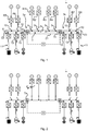
- Fig. 1 schematically shows a DC power system 1.
- the DC power system 1 comprises a main bus 3, namely a main DC bus, also known as a DC grid.
- the main DC bus 3 has a first bus section 3a, namely a first DC bus section and a second bus section 3b, namely a second DC bus section.
- the DC power system 1 further comprises a switch 3c, for example a bus-tie, which is arranged to connect and disconnect the first DC bus section 3a and the second DC bus section 3b.
- the DC power system 1 comprises power delivery devices G1 to G4 in the form of power generating units.
- power delivery devices G1 and G2 are configured to be connected to the first DC bus section 3a and power delivery devices G3 and G4 are configured to be connected to the second DC bus section 3b.
- Each power delivery G1 to G4 may for example be an AC power source, e.g. a diesel generator or a gas engine.
- the DC power system 1 may thus comprise a plurality of rectifiers R1 to R4, one rectifier R1 to R4 for each power delivery device G1 to G4.
- Each rectifier R1 to R4 is configured to be connected to a respective power delivery device G1 to G4 and to the main bus 3.
- Each rectifier R1 to R4 thus has terminals configured to be connected to a respective power delivery device G1 to G4 and terminals configured to be connected to the main bus 3.
- the DC power system 1 comprises disconnecting devices 5 such as air circuit breakers, disconnectors, or contactors, for selectively disconnecting a respective one of the rectifiers R1-R4, and thus the power delivery devices G1-G4 from the main bus 3.
- disconnecting devices 5 such as air circuit breakers, disconnectors, or contactors, for selectively disconnecting a respective one of the rectifiers R1-R4, and thus the power delivery devices G1-G4 from the main bus 3.
- the main bus 3 is configured to be segregated into different protection zones referred to as second protection zone and first protection zone.
- the segregation is provided by means of zone partitioning devices, as will be described in more detail in the following.
- the section of the main bus 3 to which the power delivery devices G1-G4 are configured to be connected is the second protection zone Z1.
- power delivery devices with longer fault clearance requirements are configured to be connected to the main bus 3.
- no power converters comprising integrated capacitor banks are connected to or configured to be connected to the second protection zone Z1.
- the exemplified DC power system 1 also comprises a plurality of power delivery devices G5 to G8 and 11-15, at least some of them having fast fault clearance requirements, configured to be connected to a respective first protection zone Z2 and Z3.
- the DC power system 1 also comprises a plurality of disconnecting devices 6 configured to be connected between a respective power delivery device 11-15 and the main bus 3, and a plurality of disconnecting devices 10 configured to be connected between the main bus 3 and respective power delivery devices G5 to G8.
- the disconnecting devices 6, 10 are configured to selectively disconnect a respective one of the power delivery devices G5-G8 and 11-15, respectively, from the main bus 3.
- the exemplified power delivery devices G5 to G8 are AC power generating units, e.g. diesel generators or gas engines.
- the exemplified DC power system 1 therefore comprises rectifiers R5-R8, and the power delivery devices G5 to G8 are configured to be connected to the main bus 3 via a respective rectifier R5-R8.
- Rectifiers R5-R8 may be provided with switchable rectifier bridges, for example thyristor-based rectifier bridges, able to block fast transient fault currents from discharging of capacitors in the event of e.g. a rectifier fault or power delivery device fault.
- Power delivery devices G5-G8 are hence configured to be installed in a fast-transient fault current environment.
- the DC power system 1 further comprises a first zone partitioning device 7a which segregates the main bus 3 into the second protection zone Z1 and first protection zone Z2, and a second zone partitioning device 7b which segregates the main bus 3 into the grid zone Z1 and first protection zone Z3.
- the first zone partitioning device 7a and the second zone partitioning device 7b may for example be solid state circuit breakers.
- the DC power system 1 also includes a control system 9 configured to control the first zone partitioning device 7a and the second zone partitioning device 7b.
- the control system 9 is configured to control the first zone partitioning device 7a to allow load current to flow from the first protection zone Z2 to the second protection zone Z1 and to limit or prevent fault current to flow from the first protection zone Z2 to the second protection zone Z1.
- the control system 9 may additionally be configured to control the first zone partitioning device 7a to allow load current and fault current to flow from the second protection zone Z1 to the first protection zone Z2.
- the control system 9 is further configured to control the second zone partitioning device 7b to allow load current to flow from the first protection zone Z3 to the second protection zone Z1 and to limit or prevent fault current to flow from the first protection zone Z3 to the second protection zone Z1.
- the control system 9 may additionally be configured to control the second zone partitioning device 7b to allow load current and fault current to flow from the second protection zone Z1 to the first protection zone Z3.
- the control system 9 may thus be configured to obtain or receive measurements or estimates of currents flowing in the system or other electrical parameters such as voltages, and in the event a fault is detected, the control system 9 controls the zone partitioning devices 7a and 7b accordingly.
- the power delivery devices 11 configured to be connected to the first bus section 3a and the second bus section 3b of the main bus 3, are exemplified by a system comprising an energy storage unit, such as a battery, and a DC/DC converter, and are thus connected to the first protection zone Z2 and first protection zone Z3, respectively.
- Power delivery devices 13 and 15 are inverters, configured to feed e.g. a motor M.
- Any of the converters of the power delivery devices 11-15 may comprise an integrated capacitor bank that is configured to support the DC link voltage. It is these capacitor banks that cause fast transients when the capacitors discharge in the event of a fault.
- Fig. 2 shows an example of a situation in which a fault F occurs in the proximity of power delivery device G1.
- the bus-tie 3c may be opened, in case the first bus section 3a and the second bus section 3b have previously been connected to disconnect the second bus section 3b from the fault.
- the control system 9 will in this case send control signals to the first zone partitioning device 7a, which as a result will block or limit fault currents from flowing from the first protection zone Z2 into the second protection zone Z1.
- the fault F may then be handled in accordance with the lower fault clearance requirements in the second protection zone Z1.
- the DC power system may comprise a monitoring system which in the event of a fault in a second protection zone is configured to monitor the limited fault current allowed by the respective zone partitioning device(s) to flow from the first protection zone(s) to a second protection zone to thereby determine whether the fault has been cleared or not.
- a monitoring system which in the event of a fault in a second protection zone is configured to monitor the limited fault current allowed by the respective zone partitioning device(s) to flow from the first protection zone(s) to a second protection zone to thereby determine whether the fault has been cleared or not.
- zone partitioning may also be implemented for DC power system that has three or four splits, i.e. sections connectable by e.g. a bus-tie. There can also be multiple second protection zones and first protection zones per section.
- control system may comprise a plurality of controllers, each controller being configured to control a respective zone partitioning device.
- the DC power system may according to one example have a second protection zone to which no power delivery devices are connected directly.
- the second protection zone may be essentially empty, in the sense that no power delivery device is configured to be connected directly to the second protection zone, only via zone partitioning devices.
- disconnecting devices that may be present in the second protection zone, such as a bus-tie and isolator switches connected between the zone protection devices and the second protection zone. These disconnecting devices may then flexibly be selected to be cheaper and/or of slower type, unable to handle fast transients, if desired. It may therefore be beneficial to segregate or subdivide the main bus into different protection zones, i.e. first protection zone(s) and second protection zone(s) also in this case.
- at least one first protection zone may in addition to power converters include power delivery devices in the form of for example diesel generators and/or gas engines to provide power to the system.
- the DC power systems described herein may advantageously be used as an on-board power system for powering a marine vessel, for example for marine vessels utilising dynamic positioning.
- marine vessels for example for marine vessels utilising dynamic positioning.
- Examples of such vessels are cable-laying vessels, drillships, floating production, storage and offloading units (FPSO), semi-submersibles, and oil platforms.
- FPSO floating production, storage and offloading units
- the present power system is typically used in a low voltage environment, although higher voltage applications, e.g. medium voltage, are also envisaged.
Landscapes
- Engineering & Computer Science (AREA)
- Power Engineering (AREA)
- Chemical & Material Sciences (AREA)
- Combustion & Propulsion (AREA)
- Mechanical Engineering (AREA)
- Ocean & Marine Engineering (AREA)
- Direct Current Feeding And Distribution (AREA)
- Supply And Distribution Of Alternating Current (AREA)
Abstract
Description
- The present disclosure generally relates to power systems and in particular to a DC power system with redundancy capability.
- Power systems for powering motors may comprise a plurality of components, such as one or more power generation units, drives line-ups, energy storage modules and a main bus to which the aforementioned components are connectable. For reasons of safety, such systems may be designed with redundancy. This is important in e.g. marine applications, where for example in some applications it is essential that dynamic positioning of a vessel to maintain its position by using its propellers and thrusters can be guaranteed at all times.
- At some point a fault, such as a short circuit will inevitably occur in the power system, either in the busbar system, in one of the components of the system, or in a load. In case of a fault, it is important to isolate the fault from the healthy part of the system such that normal power provision can be continued by means of the healthy part, and for protecting the healthy parts from being damaged. For this purpose, a protection system is typically included in the power system. A protection system arranged to handle faults in a power system typically comprise monitoring equipment arranged to monitor electrical parameters such as currents in the power system, and circuit breakers controlled by the monitoring equipment. The circuit breakers are arranged in such a way in the power system that selective fault isolation can be obtained in case of a fault. Existing protection systems can however in some applications be both very expensive and space consuming.
-
WO2013127575 discloses a DC-power system comprising a main DC bus, a power generating unit arranged to feed the main DC bus, an isolator switch arranged between the main DC bus and the power generating unit for isolating the power generating unit from the main DC bus in case of a main DC bus fault, a drive unit arranged to be fed by the main DC bus, wherein the drive unit comprises a drive unit bus system, converter units connected to the drive unit bus system, and fuses arranged between the drive unit bus system and the converter units for protecting the converter units in case of a drive unit fault. Thereby, the various units in the DC-power system can selectively be protected in case of faults in any of the units or on the main DC bus, without the use of large, space consuming and expensive circuit breakers. - The present inventor has realised that the protection philosophy disclosed in
WO2013127575 may be simplified and that the flexibility of the protection strategy may be improved. - Fuses/semiconductors and isolator switches have different operating speed capabilities. Fault currents from various parts of the system may have a clear transient character, or they may be generated more slowly, depending on the source of the fault current. An example of a transient type of fault current is obtained due to the discharging of capacitors in the converter units connected to the main DC bus. Thus, for example, a fault close to a power generating unit can cause discharging of any capacitors of the converter units.
- In view of the above, an object of the present disclosure is to provide a DC power system which solves, or at least mitigates, the problems of the prior art.
- There is hence provided a DC power system, comprising: a main bus, a plurality of power delivery devices configured to be connected to the main bus, a first zone partitioning device, and a control system, wherein the first zone partitioning device is configured to segregate the main bus into a first protection zone which is a section of the main bus to which power delivery devices with a fault clearance requirement in a first time range are configured to be connected, and a second protection zone which is a section of the main bus with a fault clearance requirement in a second time range, which includes times that are higher than any time included in the first time range, and to which no power delivery device with a fault clearance requirement in the first time range is configured to be connected, wherein the control system is configured to control the first zone partitioning device to allow load current to flow from the first protection zone to the second protection zone and to limit fault current flow from the first protection zone to the second protection zone.
- The first zone partitioning device quickly segregates the second protection zone from the first protection zone in the event of a fault in the second protection zone, whereby transient fault currents arising in the first protection zone can be limited or prevented from flowing into the second protection zone, thereby preventing negative impact on the power delivery devices, such as power converters, in the first protection zone. It furthermore allows for a more flexible approach to protection, where higher performance protection devices may be used in the first protection zone to provide quick fault handling in the first protection zone, and lower performance protection devices may be used in the second protection zone, where a plurality of strategies for fault handling may be utilised.
- According to one embodiment the control system is configured to control the first zone partitioning device to allow load current to flow from the first protection zone to the second protection zone and to prevent fault current flow from the first protection zone to the second protection zone.
- The first protection zone is characterized by the fact that most power delivery devices in the form of power converters configured to be connected to it has integrated capacitor banks that support the dc link voltage. The power converters depend on these for their operation and if the voltage on these capacitors falls below a certain level the power converters trip on under voltage. The capacitive nature of the dc-link also means that fault currents in this zone have very short time constants and consequently reach high levels within very short time after a fault. This also means that any faults in the first protection zone must be handled extremely quickly to avoid adverse effects on its converters. This environment is ideally suited to solid state circuit breakers and high speed fuses which clear faults in range of a few microseconds to a few milliseconds. The first zone partitioning device ensures that faults outside the particular first protection zone do not immediately cause the converters to trip on under voltage.
- The second protection zone is characterized by fault currents with longer time constants and any power converters connected to it are not dependent on capacitor banks on their dc terminals to operate. This means that it is possible to use a slower-acting protection approach in this zone. All entry points from other zone(s) of the main bus into the second protection zone are guarded by zone partitioning devices that can control fault current. This can be used to, according to one example, implement a fold-back protection scheme whereby a sustained fault current triggers a reduction in grid voltage and fault current. The faulty section or component is disconnected from the system and the voltage ramped up again. Faults in this zone are typically cleared in 2-500ms.
- The first protection zone may be a capacitive zone and the second protection zone may be a DC grid zone.
- According to one embodiment the control system is configured to control the first zone partitioning device to allow load current and fault current to flow from the second protection zone to the first protection zone.
- According to one embodiment the first zone partitioning device is a solid state circuit breaker.
- One embodiment comprises a rectifier, wherein at least one of the power delivery devices configured to be connected to the second protection zone is a diesel generator or a gas engine, wherein the diesel generator or gas engine is configured to be connected to the main bus via the rectifier.
- According to one embodiment at least one of the power delivery devices is a power converter comprising a capacitor bank, wherein the power converter is configured to be connected to the first protection zone.
- According to one embodiment at least one of the power delivery devices configured to be connected to the first protection zone is an energy storage unit.
- According to one embodiment at least one of the power delivery devices configured to be connected to the first protection zone is a generator, for example a diesel generator.
- According to one embodiment the first time range and the second time range partially overlap.
- According to one embodiment the first time range and the second time range are disjoint.
- According to one embodiment the first time range includes times ranging from in the order of one micro second to the order of one millisecond.
- According to one embodiment the second time range includes times ranging from in the order of one millisecond to the order of hundreds of milliseconds.
- One embodiment comprises a bus-tie, wherein the main bus is separable into a first bus section and a second bus section by means of the bus-tie, wherein the first zone partitioning device is configured to segregate the first bus section into the first protection zone and the second protection zone, and wherein the DC power system comprises a second zone partitioning device, wherein the second zone partitioning device is configured to segregate the second bus section into a first protection zone which is a section of the second bus section to which power delivery devices with a fault clearance requirement in the first time range are configured to be connected, and a second protection zone which is a section of the main bus with a fault clearance requirement in the second time range and to which no power delivery device with a fault clearance requirement in the first time range is configured to be connected, wherein the control system is configured to control the second zone partitioning device to allow load current to flow from the first protection zone to the second protection zone and to limit fault current flow from the first protection zone to the second protection zone.
- According to one embodiment the control system is configured to control the second zone partitioning device to allow load current to flow from the first protection zone to the second protection zone and to prevent fault current flow from the first protection zone to the second protection zone.
- According to one embodiment the control system is configured to control the second zone partitioning device to allow load current and fault current to flow from the second protection zone to the first protection zone.
- One embodiment comprises a plurality of disconnecting devices, each disconnecting device being configured to be connected between the main bus and a respective power delivery device to enable disconnection of the power delivery devices from the main bus.
- According to one embodiment at least some of the disconnecting devices configured to disconnect power delivery devices configured to be connected to the first protection zone are one of solid state circuit breakers and fuses, for example high-speed fuses.
- Disconnecting devices configured to disconnect power delivery devices that are configured to be connected to the second protection zone may be isolator switches, contactors or air circuit breakers.
- According to one embodiment the DC power system is an on-board power system of a vessel.
- One embodiment comprises a monitoring system which in the event of a fault in the second protection zone is configured to monitor a limited fault current allowed by the first zone partitioning device to flow from the first protection zone to the second protection zone to thereby determine whether the fault has been cleared.
- There is according to a second aspect of the present disclosure provided a marine vessel comprising a DC power system according to the first aspect.
- According to one embodiment the marine vessel is a dynamic positioning vessel.
- Generally, all terms used in the claims are to be interpreted according to their ordinary meaning in the technical field, unless explicitly defined otherwise herein. All references to "a/an/the element, apparatus, component, means, etc. are to be interpreted openly as referring to at least one instance of the element, apparatus, component, means, etc., unless explicitly stated otherwise.
- The specific embodiments of the inventive concept will now be described, by way of example, with reference to the accompanying drawings, in which:
-
Fig. 1 is a schematic diagram of an example of a DC power system; and -
Fig. 2 schematically shows one example of operation of the DC power system inFig. 1 . - The inventive concept will now be described more fully hereinafter with reference to the accompanying drawings, in which exemplifying embodiments are shown. The inventive concept may, however, be embodied in many different forms and should not be construed as limited to the embodiments set forth herein; rather, these embodiments are provided by way of example so that this disclosure will be thorough and complete, and will fully convey the scope of the inventive concept to those skilled in the art. Like numbers refer to like elements throughout the description.
- The present disclose relates to a DC power system which includes a main bus, a plurality of power delivery devices, a plurality of disconnecting devices or protection devices, a control system, and a first zone partitioning device. Each power delivery device is configured to be connected to the main bus by means of a respective disconnecting device. The disconnecting devices are configured to disconnect the respective power delivery devices from the main bus.
- The first zone partitioning device is configured to segregate the main bus into a first protection zone and a second protection zone. The first protection zone and the second protection zone form two types of protection zones.
- The first protection zone is one which is characterised by fast fault clearance requirements, and the second protection zone is one which is characterised by slower fault clearance requirements than the first protection zone. The fault clearance requirements are created by the particular power delivery devices configured to be connected to the main bus. A section of the main bus to which power delivery devices with fast fault clearance requirements are configured to be connected is a first protection zone. A section of the main bus to which power delivery devices with slower fault clearance requirements are configured to be connected, and to which no power delivery devices with fast fault clearance requirements are configured to be connected is a second protection zone.
- The fault clearance requirement in the first protection zone is within a first time range. The first time range includes times ranging from in the order of one micro second to the order of one millisecond. The fault clearance requirement in the second protection zone is within a second time range, which includes times that are higher than any time included in the first time range. The first time range and the second time range may have a partial overlap, or the may be disjoint. The second time range includes times ranging from in the order of one millisecond to the order of hundreds of milliseconds.
- The control system is configured to control the first zone partitioning device to allow load current to flow from the first protection zone to the second protection zone and to limit or prevent fault current to flow from the first protection zone to the second protection zone. The control system may furthermore be configured to control the first zone partitioning device to allow load current and fault current to flow from the second protection zone to the first protection zone.
- All entry points from sections of the main bus outside the second protection zone into the second protection zone are guarded by a respective zone partitioning devices, thereby limiting or preventing fault currents to flow from a first protection zone to the second protection zone.
- An example of a DC power system will now be described with reference to
Fig. 1 . -
Fig. 1 schematically shows aDC power system 1. TheDC power system 1 comprises amain bus 3, namely a main DC bus, also known as a DC grid. Themain DC bus 3 has afirst bus section 3a, namely a first DC bus section and asecond bus section 3b, namely a second DC bus section. TheDC power system 1 further comprises aswitch 3c, for example a bus-tie, which is arranged to connect and disconnect the firstDC bus section 3a and the secondDC bus section 3b. - The
DC power system 1 comprises power delivery devices G1 to G4 in the form of power generating units. According to the present example power delivery devices G1 and G2 are configured to be connected to the firstDC bus section 3a and power delivery devices G3 and G4 are configured to be connected to the secondDC bus section 3b. - Each power delivery G1 to G4 may for example be an AC power source, e.g. a diesel generator or a gas engine. The
DC power system 1 may thus comprise a plurality of rectifiers R1 to R4, one rectifier R1 to R4 for each power delivery device G1 to G4. Each rectifier R1 to R4 is configured to be connected to a respective power delivery device G1 to G4 and to themain bus 3. Each rectifier R1 to R4 thus has terminals configured to be connected to a respective power delivery device G1 to G4 and terminals configured to be connected to themain bus 3. - The
DC power system 1 comprises disconnectingdevices 5 such as air circuit breakers, disconnectors, or contactors, for selectively disconnecting a respective one of the rectifiers R1-R4, and thus the power delivery devices G1-G4 from themain bus 3. - The
main bus 3 is configured to be segregated into different protection zones referred to as second protection zone and first protection zone. The segregation is provided by means of zone partitioning devices, as will be described in more detail in the following. - The section of the
main bus 3 to which the power delivery devices G1-G4 are configured to be connected is the second protection zone Z1. Here only power delivery devices with longer fault clearance requirements are configured to be connected to themain bus 3. Thus, no power converters comprising integrated capacitor banks are connected to or configured to be connected to the second protection zone Z1. - The exemplified
DC power system 1 also comprises a plurality of power delivery devices G5 to G8 and 11-15, at least some of them having fast fault clearance requirements, configured to be connected to a respective first protection zone Z2 and Z3. TheDC power system 1 also comprises a plurality of disconnecting devices 6 configured to be connected between a respective power delivery device 11-15 and themain bus 3, and a plurality of disconnectingdevices 10 configured to be connected between themain bus 3 and respective power delivery devices G5 to G8. Thedisconnecting devices 6, 10 are configured to selectively disconnect a respective one of the power delivery devices G5-G8 and 11-15, respectively, from themain bus 3. - The exemplified power delivery devices G5 to G8 are AC power generating units, e.g. diesel generators or gas engines. The exemplified
DC power system 1 therefore comprises rectifiers R5-R8, and the power delivery devices G5 to G8 are configured to be connected to themain bus 3 via a respective rectifier R5-R8. Rectifiers R5-R8 may be provided with switchable rectifier bridges, for example thyristor-based rectifier bridges, able to block fast transient fault currents from discharging of capacitors in the event of e.g. a rectifier fault or power delivery device fault. Power delivery devices G5-G8 are hence configured to be installed in a fast-transient fault current environment. - The
DC power system 1 further comprises a firstzone partitioning device 7a which segregates themain bus 3 into the second protection zone Z1 and first protection zone Z2, and a secondzone partitioning device 7b which segregates themain bus 3 into the grid zone Z1 and first protection zone Z3. - The first
zone partitioning device 7a and the secondzone partitioning device 7b may for example be solid state circuit breakers. - The
DC power system 1 also includes acontrol system 9 configured to control the firstzone partitioning device 7a and the secondzone partitioning device 7b. In particular, thecontrol system 9 is configured to control the firstzone partitioning device 7a to allow load current to flow from the first protection zone Z2 to the second protection zone Z1 and to limit or prevent fault current to flow from the first protection zone Z2 to the second protection zone Z1. Thecontrol system 9 may additionally be configured to control the firstzone partitioning device 7a to allow load current and fault current to flow from the second protection zone Z1 to the first protection zone Z2. - The
control system 9 is further configured to control the secondzone partitioning device 7b to allow load current to flow from the first protection zone Z3 to the second protection zone Z1 and to limit or prevent fault current to flow from the first protection zone Z3 to the second protection zone Z1. Thecontrol system 9 may additionally be configured to control the secondzone partitioning device 7b to allow load current and fault current to flow from the second protection zone Z1 to the first protection zone Z3. - The
control system 9 may thus be configured to obtain or receive measurements or estimates of currents flowing in the system or other electrical parameters such as voltages, and in the event a fault is detected, thecontrol system 9 controls thezone partitioning devices power delivery devices 11 configured to be connected to thefirst bus section 3a and thesecond bus section 3b of themain bus 3, are exemplified by a system comprising an energy storage unit, such as a battery, and a DC/DC converter, and are thus connected to the first protection zone Z2 and first protection zone Z3, respectively. -
Power delivery devices -
Fig. 2 shows an example of a situation in which a fault F occurs in the proximity of power delivery device G1. There are a number of strategies of how to handle a fault of this type, as for example disclosed inWO2013127575 , and fault-handling strategies will therefore not be described in any detail herein. Returning now to the example inFig. 2 , the bus-tie 3c may be opened, in case thefirst bus section 3a and thesecond bus section 3b have previously been connected to disconnect thesecond bus section 3b from the fault. Furthermore, thecontrol system 9 will in this case send control signals to the firstzone partitioning device 7a, which as a result will block or limit fault currents from flowing from the first protection zone Z2 into the second protection zone Z1. The fault F may then be handled in accordance with the lower fault clearance requirements in the second protection zone Z1. - According to one example the DC power system may comprise a monitoring system which in the event of a fault in a second protection zone is configured to monitor the limited fault current allowed by the respective zone partitioning device(s) to flow from the first protection zone(s) to a second protection zone to thereby determine whether the fault has been cleared or not. By allowing a limited amount of fault current from the first protection zone(s) to flow to a fault, detection of whether the fault has been cleared or not may be facilitated.
- It should be noted that the herein described zone partitioning, exemplified above with 2-split system, may also be implemented for DC power system that has three or four splits, i.e. sections connectable by e.g. a bus-tie. There can also be multiple second protection zones and first protection zones per section.
- It should furthermore be noted that the control system may comprise a plurality of controllers, each controller being configured to control a respective zone partitioning device.
- The DC power system may according to one example have a second protection zone to which no power delivery devices are connected directly. In this case, the second protection zone may be essentially empty, in the sense that no power delivery device is configured to be connected directly to the second protection zone, only via zone partitioning devices. There may still be benefits in this type of configuration, due to disconnecting devices that may be present in the second protection zone, such as a bus-tie and isolator switches connected between the zone protection devices and the second protection zone. These disconnecting devices may then flexibly be selected to be cheaper and/or of slower type, unable to handle fast transients, if desired. It may therefore be beneficial to segregate or subdivide the main bus into different protection zones, i.e. first protection zone(s) and second protection zone(s) also in this case. In this set-up, at least one first protection zone may in addition to power converters include power delivery devices in the form of for example diesel generators and/or gas engines to provide power to the system.
- The DC power systems described herein may advantageously be used as an on-board power system for powering a marine vessel, for example for marine vessels utilising dynamic positioning. Examples of such vessels are cable-laying vessels, drillships, floating production, storage and offloading units (FPSO), semi-submersibles, and oil platforms. The present power system is typically used in a low voltage environment, although higher voltage applications, e.g. medium voltage, are also envisaged.
- The inventive concept has mainly been described above with reference to a few examples. However, as is readily appreciated by a person skilled in the art, other embodiments than the ones disclosed above are equally possible within the scope of the inventive concept, as defined by the appended claims.
Claims (16)
- A DC power system (1), comprising:a main bus (3),a plurality of power delivery devices (G1-G8, 11-15) configured to be connected to the main bus (3),a first zone partitioning device (7a), anda control system (9),wherein the first zone partitioning device (7a) is configured to segregate the main bus (3) into a first protection zone (Z2) which is a section of the main bus (3) to which power delivery devices (11-15) with a fault clearance requirement in a first time range are configured to be connected, and a second protection zone (Z1) which is a section of the main bus (3) with a fault clearance requirement in a second time range, which includes times that are higher than any time included in the first time range, and to which no power delivery device (11-15) with a fault clearance requirement in the first time range is configured to be connected,
wherein the control system (9) is configured to control the first zone partitioning device (7a) to allow load current to flow from the first protection zone (Z2) to the second protection zone (Z1) and to limit fault current flow from the first protection zone (Z2) to the second protection zone (Z1). - The DC power system (1) as claimed in claim 1, wherein the control system (9) is configured to control the first zone partitioning device (7a) to allow load current and fault current to flow from the second protection zone (Z1) to the first protection zone (Z2).
- The DC power system (1) as claimed in claim 1 or 2, wherein the first zone partitioning device (7a) is a solid state circuit breaker.
- The DC power system (1) as claimed in any of the preceding claims, comprising a power delivery device (G1-G4) with a fault clearance requirement in a second time range and a rectifier (R1-R4), wherein the power delivery device (G1-G4) is configured to be connected to the second protection zone (Z1) via the rectifier (R1-R4).
- The DC power system (1) as claimed in any of the preceding claims, wherein at least one of the power delivery devices (11-15) is a power converter comprising a capacitor bank, wherein the power converter is configure to be connected to the first protection zone (Z2).
- The DC power system (1) as claimed in any of the preceding claims, wherein the first time range and the second time range partially overlap.
- The DC power system (1) as claimed in any of the preceding claims, wherein the first time range and the second time range are disjoint.
- The DC power system (1) as claimed in any of the preceding claims, wherein the first time range includes times ranging from in the order of one micro second to the order of one millisecond.
- The DC power system (1) as claimed in any of the preceding claims, wherein the second time range includes times ranging from in the order of one millisecond to the order of hundreds of milliseconds.
- The DC power system (1) as claimed in any of the preceding claims, comprising a bus-tie (3c), wherein the main bus (3) is separable into a first bus section (3a) and a second bus section (3b) by means of the bus-tie (3c), wherein the first zone partitioning device (7a) is configured to segregate the first bus section (3a) into the first protection zone (Z2) and the second protection zone (Z1), and
wherein the DC power system (1) comprises a second zone partitioning device (7b), wherein the second zone partitioning device (7b) is configured to segregate the second bus section (3) into a first protection zone (Z3) which is a section of the second bus section (3b) to which power delivery devices (11-15) with a fault clearance requirement in the first time range are configured to be connected, and a second protection zone (Z1) which is a section of the main bus (3) with a fault clearance requirement in the second time range, and to which no power delivery device (11-15) with a fault clearance requirement in the first time range is configured to be connected, wherein the control system (9) is configured to control the second zone partitioning device (7b) to allow load current to flow from the first protection zone (Z3) to the second protection zone (Z1) and to limit fault current flow from the first protection zone (Z3) to the second protection zone (Z1). - The DC power system (1) as claimed in claim 10, wherein the control system (9) is configured to control the second zone partitioning device (7b) to allow load current and fault current to flow from the second protection zone (Z3) to the first protection zone (Z1).
- The DC power system (1) as claimed in any of the preceding claims, comprising a plurality of disconnecting devices (6, 10), each disconnecting device (5, 6, 10) being configured to be connected between the main bus (3) and a respective power delivery device (G5-G8, 11-15) to enable disconnection of the power delivery devices (G5-G8, 11-15) from the main bus (3).
- The DC power system (1) as claimed in claim 12, wherein at least some of the disconnecting devices (6) configured to disconnect power delivery devices (11-15) configured to be connected to the first protection zone (Z2, Z3) are one of solid state circuit breakers and fuses.
- The DC power system (1) as claimed in any of the preceding claims, comprising a monitoring system which in the event of a fault in the second protection zone is configured to monitor a limited fault current allowed by the first zone partitioning device to flow from the first protection zone to the second protection zone to thereby determine whether the fault has been cleared.
- A marine vessel comprising a DC power system (1) as claimed in any of claims 1-14.
- The marine vessel as claimed in claim 15, wherein the marine vessel is a dynamic positioning vessel.
Priority Applications (8)
| Application Number | Priority Date | Filing Date | Title |
|---|---|---|---|
| DK16198226.9T DK3322057T3 (en) | 2016-11-10 | 2016-11-10 | DC POWER SYSTEM DIVIDED INTO DIFFERENT PROTECTION AREAS |
| ES16198226T ES2898710T3 (en) | 2016-11-10 | 2016-11-10 | A separate DC power system in different protection zones |
| EP16198226.9A EP3322057B1 (en) | 2016-11-10 | 2016-11-10 | A dc power system segregated into different protection zones |
| CN201780069730.9A CN109923746B (en) | 2016-11-10 | 2017-10-30 | DC power system divided into different protection zones |
| US16/346,413 US10608427B2 (en) | 2016-11-10 | 2017-10-30 | DC power system segregated into different protection zones |
| PCT/EP2017/077724 WO2018086927A1 (en) | 2016-11-10 | 2017-10-30 | A dc power system segregated into different protection zones |
| SG11201903258WA SG11201903258WA (en) | 2016-11-10 | 2017-10-30 | A dc power system segregated into different protection zones |
| KR1020197012637A KR102116209B1 (en) | 2016-11-10 | 2017-10-30 | DC power system separated into different protection zones |
Applications Claiming Priority (1)
| Application Number | Priority Date | Filing Date | Title |
|---|---|---|---|
| EP16198226.9A EP3322057B1 (en) | 2016-11-10 | 2016-11-10 | A dc power system segregated into different protection zones |
Publications (2)
| Publication Number | Publication Date |
|---|---|
| EP3322057A1 true EP3322057A1 (en) | 2018-05-16 |
| EP3322057B1 EP3322057B1 (en) | 2021-09-29 |
Family
ID=57281160
Family Applications (1)
| Application Number | Title | Priority Date | Filing Date |
|---|---|---|---|
| EP16198226.9A Active EP3322057B1 (en) | 2016-11-10 | 2016-11-10 | A dc power system segregated into different protection zones |
Country Status (8)
| Country | Link |
|---|---|
| US (1) | US10608427B2 (en) |
| EP (1) | EP3322057B1 (en) |
| KR (1) | KR102116209B1 (en) |
| CN (1) | CN109923746B (en) |
| DK (1) | DK3322057T3 (en) |
| ES (1) | ES2898710T3 (en) |
| SG (1) | SG11201903258WA (en) |
| WO (1) | WO2018086927A1 (en) |
Cited By (2)
| Publication number | Priority date | Publication date | Assignee | Title |
|---|---|---|---|---|
| EP3921930A1 (en) * | 2019-03-22 | 2021-12-15 | Siemens Aktiengesellschaft | Circuit breaker device for dc voltage |
| EP4398432A1 (en) * | 2023-01-03 | 2024-07-10 | Siemens Energy Global GmbH & Co. KG | Method for operating a high-voltage dc network |
Families Citing this family (5)
| Publication number | Priority date | Publication date | Assignee | Title |
|---|---|---|---|---|
| US10958076B2 (en) * | 2016-12-21 | 2021-03-23 | Single Buoy Moorings Inc. | Power generation and distribution arrangement and floating unit comprising such an arrangement |
| GB2574039B (en) * | 2018-05-24 | 2021-04-14 | Caterpillar Inc | A power distribution system for a marine vessel |
| US11605949B2 (en) | 2020-07-20 | 2023-03-14 | Abb Schweiz Ag | Electrification arrangement for supplying power to electrical loads |
| CN115697753B (en) * | 2021-05-21 | 2025-12-05 | 深圳引望智能技术有限公司 | Power distribution equipment, vehicles and troubleshooting methods |
| KR102687863B1 (en) | 2022-05-30 | 2024-07-25 | 에이치디현대일렉트릭 주식회사 | Portection method and protect system of ship's power distribution system |
Citations (3)
| Publication number | Priority date | Publication date | Assignee | Title |
|---|---|---|---|---|
| WO2013127575A1 (en) | 2012-02-29 | 2013-09-06 | Abb Technology Ltd | A dc-power system with system protection capabilities |
| US20130270902A1 (en) * | 2012-04-17 | 2013-10-17 | Siemens Aktiengesellschaft | Fault Protection System For A Power System Of Dynamically Positioned Vessel |
| US20140022680A1 (en) * | 2011-03-11 | 2014-01-23 | Abb Technology Ag | Current limitation system for limiting the effects of a fault in a dc grid and a method of operating a current limitation system |
Family Cites Families (20)
| Publication number | Priority date | Publication date | Assignee | Title |
|---|---|---|---|---|
| US4924342A (en) * | 1987-01-27 | 1990-05-08 | Teledyne Inet | Low voltage transient current limiting circuit |
| EP2206293B1 (en) * | 2007-10-02 | 2015-03-04 | Microchip Technology Germany GmbH | System and method for signal failure detection in a ring bus system |
| CN101836342B (en) * | 2007-10-22 | 2013-02-06 | 西门子公司 | Electrical switchgear, particularly for connecting generators and thrusters in dynamically positioned vessels, and operation method thereof |
| US10324132B2 (en) * | 2010-06-07 | 2019-06-18 | Abb Inc. | Systems and methods for power line event zone identification |
| WO2012000545A1 (en) * | 2010-06-30 | 2012-01-05 | Abb Technology Ag | An hvdc transmission system, an hvdc station and a method of operating an hvdc station |
| EP2684268B1 (en) * | 2011-03-11 | 2020-01-01 | ABB Schweiz AG | A dc grid and a method of limiting the effects of a fault in a dc grid |
| KR20130020215A (en) * | 2011-08-19 | 2013-02-27 | 대우조선해양 주식회사 | Power distrubution apparatus for dynamic positioning vessel |
| CN202333963U (en) * | 2011-11-22 | 2012-07-11 | 重庆市电力公司检修分公司 | Direct-current dual power intelligent seamless switching device |
| US8564914B2 (en) * | 2012-02-21 | 2013-10-22 | Sikorsky Aircraft Corporation | Fault clearing without a DC backup power source |
| DK2654156T3 (en) * | 2012-04-17 | 2021-08-09 | Siemens Energy AS | Fault protection system for power supply system of dynamically positioned vessel |
| CN102689685B (en) * | 2012-06-01 | 2014-08-06 | 哈尔滨工程大学 | Dynamic positioning vessel thruster load limit method based on on-line available power |
| EP2907209A1 (en) | 2012-12-13 | 2015-08-19 | Siemens Aktiengesellschaft | Switch arrangement of a d.c. voltage network |
| CN103124102A (en) * | 2012-12-19 | 2013-05-29 | 上海艾能电力工程有限公司 | Shore power system for dock high-voltage ships |
| EP2910959B1 (en) * | 2014-02-19 | 2021-09-08 | General Electric Technology GmbH | Fault location in DC networks |
| CN107210603B (en) * | 2014-05-04 | 2020-07-14 | Abb瑞士股份有限公司 | Fault Protection in Converter-Based DC Power Distribution Systems |
| US9744925B2 (en) * | 2014-07-31 | 2017-08-29 | General Electric Company | DC power system for marine applications |
| US9780643B2 (en) | 2014-09-22 | 2017-10-03 | General Electric Company | DC power system for marine applications |
| US9557794B2 (en) * | 2014-11-07 | 2017-01-31 | General Electric Company | System and method for distributing electrical power |
| EP3035477A1 (en) | 2014-12-19 | 2016-06-22 | ABB Technology Ltd | A power system comprising a central energy storage system and a method of controlling power transfer in a power system |
| CN106058829B (en) * | 2016-07-22 | 2018-08-17 | 广东电网有限责任公司揭阳供电局 | Fault protection system for power distribution system |
-
2016
- 2016-11-10 DK DK16198226.9T patent/DK3322057T3/en active
- 2016-11-10 ES ES16198226T patent/ES2898710T3/en active Active
- 2016-11-10 EP EP16198226.9A patent/EP3322057B1/en active Active
-
2017
- 2017-10-30 US US16/346,413 patent/US10608427B2/en active Active
- 2017-10-30 KR KR1020197012637A patent/KR102116209B1/en active Active
- 2017-10-30 WO PCT/EP2017/077724 patent/WO2018086927A1/en not_active Ceased
- 2017-10-30 SG SG11201903258WA patent/SG11201903258WA/en unknown
- 2017-10-30 CN CN201780069730.9A patent/CN109923746B/en active Active
Patent Citations (4)
| Publication number | Priority date | Publication date | Assignee | Title |
|---|---|---|---|---|
| US20140022680A1 (en) * | 2011-03-11 | 2014-01-23 | Abb Technology Ag | Current limitation system for limiting the effects of a fault in a dc grid and a method of operating a current limitation system |
| WO2013127575A1 (en) | 2012-02-29 | 2013-09-06 | Abb Technology Ltd | A dc-power system with system protection capabilities |
| US20140361621A1 (en) * | 2012-02-29 | 2014-12-11 | John Lindtjorn | DC-Power System With System Protection Capabilities |
| US20130270902A1 (en) * | 2012-04-17 | 2013-10-17 | Siemens Aktiengesellschaft | Fault Protection System For A Power System Of Dynamically Positioned Vessel |
Cited By (2)
| Publication number | Priority date | Publication date | Assignee | Title |
|---|---|---|---|---|
| EP3921930A1 (en) * | 2019-03-22 | 2021-12-15 | Siemens Aktiengesellschaft | Circuit breaker device for dc voltage |
| EP4398432A1 (en) * | 2023-01-03 | 2024-07-10 | Siemens Energy Global GmbH & Co. KG | Method for operating a high-voltage dc network |
Also Published As
| Publication number | Publication date |
|---|---|
| EP3322057B1 (en) | 2021-09-29 |
| WO2018086927A1 (en) | 2018-05-17 |
| CN109923746B (en) | 2020-06-19 |
| ES2898710T3 (en) | 2022-03-08 |
| US10608427B2 (en) | 2020-03-31 |
| US20190273376A1 (en) | 2019-09-05 |
| CN109923746A (en) | 2019-06-21 |
| KR20190051077A (en) | 2019-05-14 |
| SG11201903258WA (en) | 2019-05-30 |
| DK3322057T3 (en) | 2021-12-20 |
| KR102116209B1 (en) | 2020-05-28 |
Similar Documents
| Publication | Publication Date | Title |
|---|---|---|
| EP3322057B1 (en) | A dc power system segregated into different protection zones | |
| EP2634885B1 (en) | A DC-power system with system protection capabilities | |
| KR101413520B1 (en) | Fault protection system for a power system of dynamically positioned vessel | |
| US10084319B2 (en) | Power system comprising a central energy storage system and a method of controlling power transfer in a power system | |
| US20170373498A1 (en) | Distribution of electric energy on a vessel | |
| CN101836342B (en) | Electrical switchgear, particularly for connecting generators and thrusters in dynamically positioned vessels, and operation method thereof | |
| EP3109964A1 (en) | Dc grid | |
| US10862300B2 (en) | Power distribution system | |
| KR102115787B1 (en) | Dc shipboard power system | |
| US11381073B2 (en) | Highly redundant DC voltage network | |
| KR20220120147A (en) | Generating apparatus for ship and power distributing system for ship | |
| Gudex et al. | Multiple line-to-ground fault characterization and mitigation in mvdc shipboard electrical systems | |
| US12451684B2 (en) | Electric power distribution system with at least two bus-tie links | |
| KR20210042502A (en) | Electric power supply system for vessel | |
| HK1186850B (en) | A dc-power system with system protection capabilities |
Legal Events
| Date | Code | Title | Description |
|---|---|---|---|
| PUAI | Public reference made under article 153(3) epc to a published international application that has entered the european phase |
Free format text: ORIGINAL CODE: 0009012 |
|
| STAA | Information on the status of an ep patent application or granted ep patent |
Free format text: STATUS: THE APPLICATION HAS BEEN PUBLISHED |
|
| AK | Designated contracting states |
Kind code of ref document: A1 Designated state(s): AL AT BE BG CH CY CZ DE DK EE ES FI FR GB GR HR HU IE IS IT LI LT LU LV MC MK MT NL NO PL PT RO RS SE SI SK SM TR |
|
| AX | Request for extension of the european patent |
Extension state: BA ME |
|
| STAA | Information on the status of an ep patent application or granted ep patent |
Free format text: STATUS: REQUEST FOR EXAMINATION WAS MADE |
|
| 17P | Request for examination filed |
Effective date: 20181116 |
|
| RBV | Designated contracting states (corrected) |
Designated state(s): AL AT BE BG CH CY CZ DE DK EE ES FI FR GB GR HR HU IE IS IT LI LT LU LV MC MK MT NL NO PL PT RO RS SE SI SK SM TR |
|
| GRAP | Despatch of communication of intention to grant a patent |
Free format text: ORIGINAL CODE: EPIDOSNIGR1 |
|
| STAA | Information on the status of an ep patent application or granted ep patent |
Free format text: STATUS: GRANT OF PATENT IS INTENDED |
|
| INTG | Intention to grant announced |
Effective date: 20210517 |
|
| GRAS | Grant fee paid |
Free format text: ORIGINAL CODE: EPIDOSNIGR3 |
|
| GRAA | (expected) grant |
Free format text: ORIGINAL CODE: 0009210 |
|
| STAA | Information on the status of an ep patent application or granted ep patent |
Free format text: STATUS: THE PATENT HAS BEEN GRANTED |
|
| AK | Designated contracting states |
Kind code of ref document: B1 Designated state(s): AL AT BE BG CH CY CZ DE DK EE ES FI FR GB GR HR HU IE IS IT LI LT LU LV MC MK MT NL NO PL PT RO RS SE SI SK SM TR |
|
| REG | Reference to a national code |
Ref country code: GB Ref legal event code: FG4D |
|
| REG | Reference to a national code |
Ref country code: CH Ref legal event code: EP Ref country code: AT Ref legal event code: REF Ref document number: 1435047 Country of ref document: AT Kind code of ref document: T Effective date: 20211015 |
|
| REG | Reference to a national code |
Ref country code: DE Ref legal event code: R096 Ref document number: 602016064255 Country of ref document: DE |
|
| REG | Reference to a national code |
Ref country code: IE Ref legal event code: FG4D |
|
| REG | Reference to a national code |
Ref country code: FI Ref legal event code: FGE |
|
| REG | Reference to a national code |
Ref country code: DK Ref legal event code: T3 Effective date: 20211216 |
|
| REG | Reference to a national code |
Ref country code: NO Ref legal event code: T2 Effective date: 20210929 |
|
| REG | Reference to a national code |
Ref country code: LT Ref legal event code: MG9D |
|
| REG | Reference to a national code |
Ref country code: NL Ref legal event code: FP |
|
| PG25 | Lapsed in a contracting state [announced via postgrant information from national office to epo] |
Ref country code: SE Free format text: LAPSE BECAUSE OF FAILURE TO SUBMIT A TRANSLATION OF THE DESCRIPTION OR TO PAY THE FEE WITHIN THE PRESCRIBED TIME-LIMIT Effective date: 20210929 Ref country code: RS Free format text: LAPSE BECAUSE OF FAILURE TO SUBMIT A TRANSLATION OF THE DESCRIPTION OR TO PAY THE FEE WITHIN THE PRESCRIBED TIME-LIMIT Effective date: 20210929 Ref country code: HR Free format text: LAPSE BECAUSE OF FAILURE TO SUBMIT A TRANSLATION OF THE DESCRIPTION OR TO PAY THE FEE WITHIN THE PRESCRIBED TIME-LIMIT Effective date: 20210929 Ref country code: LT Free format text: LAPSE BECAUSE OF FAILURE TO SUBMIT A TRANSLATION OF THE DESCRIPTION OR TO PAY THE FEE WITHIN THE PRESCRIBED TIME-LIMIT Effective date: 20210929 Ref country code: BG Free format text: LAPSE BECAUSE OF FAILURE TO SUBMIT A TRANSLATION OF THE DESCRIPTION OR TO PAY THE FEE WITHIN THE PRESCRIBED TIME-LIMIT Effective date: 20211229 |
|
| REG | Reference to a national code |
Ref country code: AT Ref legal event code: MK05 Ref document number: 1435047 Country of ref document: AT Kind code of ref document: T Effective date: 20210929 |
|
| PG25 | Lapsed in a contracting state [announced via postgrant information from national office to epo] |
Ref country code: LV Free format text: LAPSE BECAUSE OF FAILURE TO SUBMIT A TRANSLATION OF THE DESCRIPTION OR TO PAY THE FEE WITHIN THE PRESCRIBED TIME-LIMIT Effective date: 20210929 Ref country code: GR Free format text: LAPSE BECAUSE OF FAILURE TO SUBMIT A TRANSLATION OF THE DESCRIPTION OR TO PAY THE FEE WITHIN THE PRESCRIBED TIME-LIMIT Effective date: 20211230 |
|
| REG | Reference to a national code |
Ref country code: ES Ref legal event code: FG2A Ref document number: 2898710 Country of ref document: ES Kind code of ref document: T3 Effective date: 20220308 |
|
| PG25 | Lapsed in a contracting state [announced via postgrant information from national office to epo] |
Ref country code: AT Free format text: LAPSE BECAUSE OF FAILURE TO SUBMIT A TRANSLATION OF THE DESCRIPTION OR TO PAY THE FEE WITHIN THE PRESCRIBED TIME-LIMIT Effective date: 20210929 |
|
| PG25 | Lapsed in a contracting state [announced via postgrant information from national office to epo] |
Ref country code: IS Free format text: LAPSE BECAUSE OF FAILURE TO SUBMIT A TRANSLATION OF THE DESCRIPTION OR TO PAY THE FEE WITHIN THE PRESCRIBED TIME-LIMIT Effective date: 20220129 Ref country code: SK Free format text: LAPSE BECAUSE OF FAILURE TO SUBMIT A TRANSLATION OF THE DESCRIPTION OR TO PAY THE FEE WITHIN THE PRESCRIBED TIME-LIMIT Effective date: 20210929 Ref country code: RO Free format text: LAPSE BECAUSE OF FAILURE TO SUBMIT A TRANSLATION OF THE DESCRIPTION OR TO PAY THE FEE WITHIN THE PRESCRIBED TIME-LIMIT Effective date: 20210929 Ref country code: PT Free format text: LAPSE BECAUSE OF FAILURE TO SUBMIT A TRANSLATION OF THE DESCRIPTION OR TO PAY THE FEE WITHIN THE PRESCRIBED TIME-LIMIT Effective date: 20220131 Ref country code: PL Free format text: LAPSE BECAUSE OF FAILURE TO SUBMIT A TRANSLATION OF THE DESCRIPTION OR TO PAY THE FEE WITHIN THE PRESCRIBED TIME-LIMIT Effective date: 20210929 Ref country code: EE Free format text: LAPSE BECAUSE OF FAILURE TO SUBMIT A TRANSLATION OF THE DESCRIPTION OR TO PAY THE FEE WITHIN THE PRESCRIBED TIME-LIMIT Effective date: 20210929 Ref country code: CZ Free format text: LAPSE BECAUSE OF FAILURE TO SUBMIT A TRANSLATION OF THE DESCRIPTION OR TO PAY THE FEE WITHIN THE PRESCRIBED TIME-LIMIT Effective date: 20210929 Ref country code: AL Free format text: LAPSE BECAUSE OF FAILURE TO SUBMIT A TRANSLATION OF THE DESCRIPTION OR TO PAY THE FEE WITHIN THE PRESCRIBED TIME-LIMIT Effective date: 20210929 |
|
| PG25 | Lapsed in a contracting state [announced via postgrant information from national office to epo] |
Ref country code: MC Free format text: LAPSE BECAUSE OF FAILURE TO SUBMIT A TRANSLATION OF THE DESCRIPTION OR TO PAY THE FEE WITHIN THE PRESCRIBED TIME-LIMIT Effective date: 20210929 |
|
| REG | Reference to a national code |
Ref country code: DE Ref legal event code: R097 Ref document number: 602016064255 Country of ref document: DE Ref country code: CH Ref legal event code: PL |
|
| PG25 | Lapsed in a contracting state [announced via postgrant information from national office to epo] |
Ref country code: LU Free format text: LAPSE BECAUSE OF NON-PAYMENT OF DUE FEES Effective date: 20211110 Ref country code: BE Free format text: LAPSE BECAUSE OF NON-PAYMENT OF DUE FEES Effective date: 20211130 |
|
| REG | Reference to a national code |
Ref country code: BE Ref legal event code: MM Effective date: 20211130 |
|
| PLBE | No opposition filed within time limit |
Free format text: ORIGINAL CODE: 0009261 |
|
| STAA | Information on the status of an ep patent application or granted ep patent |
Free format text: STATUS: NO OPPOSITION FILED WITHIN TIME LIMIT |
|
| GBPC | Gb: european patent ceased through non-payment of renewal fee |
Effective date: 20211229 |
|
| PG25 | Lapsed in a contracting state [announced via postgrant information from national office to epo] |
Ref country code: LI Free format text: LAPSE BECAUSE OF NON-PAYMENT OF DUE FEES Effective date: 20211130 Ref country code: CH Free format text: LAPSE BECAUSE OF NON-PAYMENT OF DUE FEES Effective date: 20211130 |
|
| 26N | No opposition filed |
Effective date: 20220630 |
|
| PG25 | Lapsed in a contracting state [announced via postgrant information from national office to epo] |
Ref country code: IE Free format text: LAPSE BECAUSE OF NON-PAYMENT OF DUE FEES Effective date: 20211110 Ref country code: GB Free format text: LAPSE BECAUSE OF NON-PAYMENT OF DUE FEES Effective date: 20211229 |
|
| PG25 | Lapsed in a contracting state [announced via postgrant information from national office to epo] |
Ref country code: SI Free format text: LAPSE BECAUSE OF FAILURE TO SUBMIT A TRANSLATION OF THE DESCRIPTION OR TO PAY THE FEE WITHIN THE PRESCRIBED TIME-LIMIT Effective date: 20210929 |
|
| PG25 | Lapsed in a contracting state [announced via postgrant information from national office to epo] |
Ref country code: HU Free format text: LAPSE BECAUSE OF FAILURE TO SUBMIT A TRANSLATION OF THE DESCRIPTION OR TO PAY THE FEE WITHIN THE PRESCRIBED TIME-LIMIT; INVALID AB INITIO Effective date: 20161110 |
|
| PG25 | Lapsed in a contracting state [announced via postgrant information from national office to epo] |
Ref country code: CY Free format text: LAPSE BECAUSE OF FAILURE TO SUBMIT A TRANSLATION OF THE DESCRIPTION OR TO PAY THE FEE WITHIN THE PRESCRIBED TIME-LIMIT Effective date: 20210929 |
|
| PG25 | Lapsed in a contracting state [announced via postgrant information from national office to epo] |
Ref country code: SM Free format text: LAPSE BECAUSE OF FAILURE TO SUBMIT A TRANSLATION OF THE DESCRIPTION OR TO PAY THE FEE WITHIN THE PRESCRIBED TIME-LIMIT Effective date: 20210929 |
|
| PG25 | Lapsed in a contracting state [announced via postgrant information from national office to epo] |
Ref country code: MK Free format text: LAPSE BECAUSE OF FAILURE TO SUBMIT A TRANSLATION OF THE DESCRIPTION OR TO PAY THE FEE WITHIN THE PRESCRIBED TIME-LIMIT Effective date: 20210929 |
|
| PG25 | Lapsed in a contracting state [announced via postgrant information from national office to epo] |
Ref country code: MT Free format text: LAPSE BECAUSE OF FAILURE TO SUBMIT A TRANSLATION OF THE DESCRIPTION OR TO PAY THE FEE WITHIN THE PRESCRIBED TIME-LIMIT Effective date: 20210929 |
|
| PGFP | Annual fee paid to national office [announced via postgrant information from national office to epo] |
Ref country code: NL Payment date: 20251119 Year of fee payment: 10 |
|
| PGFP | Annual fee paid to national office [announced via postgrant information from national office to epo] |
Ref country code: DE Payment date: 20251119 Year of fee payment: 10 |
|
| PGFP | Annual fee paid to national office [announced via postgrant information from national office to epo] |
Ref country code: NO Payment date: 20251125 Year of fee payment: 10 |
|
| PGFP | Annual fee paid to national office [announced via postgrant information from national office to epo] |
Ref country code: IT Payment date: 20251125 Year of fee payment: 10 Ref country code: FI Payment date: 20251125 Year of fee payment: 10 Ref country code: DK Payment date: 20251125 Year of fee payment: 10 |
|
| PGFP | Annual fee paid to national office [announced via postgrant information from national office to epo] |
Ref country code: FR Payment date: 20251126 Year of fee payment: 10 |
|
| PGFP | Annual fee paid to national office [announced via postgrant information from national office to epo] |
Ref country code: TR Payment date: 20251104 Year of fee payment: 10 |
|
| PGFP | Annual fee paid to national office [announced via postgrant information from national office to epo] |
Ref country code: ES Payment date: 20251229 Year of fee payment: 10 |