EP3321898A1 - Alarm device - Google Patents
Alarm device Download PDFInfo
- Publication number
- EP3321898A1 EP3321898A1 EP17198285.3A EP17198285A EP3321898A1 EP 3321898 A1 EP3321898 A1 EP 3321898A1 EP 17198285 A EP17198285 A EP 17198285A EP 3321898 A1 EP3321898 A1 EP 3321898A1
- Authority
- EP
- European Patent Office
- Prior art keywords
- light
- reflection cup
- alarm device
- reflective
- emitting unit
- Prior art date
- Legal status (The legal status is an assumption and is not a legal conclusion. Google has not performed a legal analysis and makes no representation as to the accuracy of the status listed.)
- Granted
Links
- 230000003287 optical effect Effects 0.000 claims abstract description 39
- 238000007142 ring opening reaction Methods 0.000 claims description 4
- 238000010586 diagram Methods 0.000 description 7
- 230000000007 visual effect Effects 0.000 description 5
- 238000004519 manufacturing process Methods 0.000 description 4
- 230000001965 increasing effect Effects 0.000 description 3
- 230000004907 flux Effects 0.000 description 2
- 238000005286 illumination Methods 0.000 description 2
- 230000000694 effects Effects 0.000 description 1
- 238000005516 engineering process Methods 0.000 description 1
- 230000002708 enhancing effect Effects 0.000 description 1
- 230000010354 integration Effects 0.000 description 1
- 238000000034 method Methods 0.000 description 1
Images


Classifications
-
- G—PHYSICS
- G08—SIGNALLING
- G08B—SIGNALLING OR CALLING SYSTEMS; ORDER TELEGRAPHS; ALARM SYSTEMS
- G08B5/00—Visible signalling systems, e.g. personal calling systems, remote indication of seats occupied
- G08B5/22—Visible signalling systems, e.g. personal calling systems, remote indication of seats occupied using electric transmission; using electromagnetic transmission
- G08B5/36—Visible signalling systems, e.g. personal calling systems, remote indication of seats occupied using electric transmission; using electromagnetic transmission using visible light sources
-
- F—MECHANICAL ENGINEERING; LIGHTING; HEATING; WEAPONS; BLASTING
- F21—LIGHTING
- F21V—FUNCTIONAL FEATURES OR DETAILS OF LIGHTING DEVICES OR SYSTEMS THEREOF; STRUCTURAL COMBINATIONS OF LIGHTING DEVICES WITH OTHER ARTICLES, NOT OTHERWISE PROVIDED FOR
- F21V7/00—Reflectors for light sources
- F21V7/10—Construction
Definitions
- the present invention generally relates to a notification device for issuing an alert to indicate an emergency, and in particular relates to a visual notification device used in a fire protection system, also called a visual alarm device (VAD) or optical alarm device.
- VAD visual alarm device
- Visual alarm devices are widely used in fire alarm systems, being used to send out a visible alarm indication, e.g. high-intensity strobe light, to on-site personnel when an emergency occurs.
- a visual alarm device (VAD) is connected to a control apparatus (control panel) via a field line or a wireless link.
- the control apparatus can trigger the VAD via the field line, such that the VAD emits high-intensity alarm light visible to the human eye, to prompt on-site personnel to promptly evacuate a region of danger.
- a VAD may be installed on a ceiling (abbreviated as “top-mounted” or on a wall (abbreviated as “wall-mounted”).
- Fig. 1 demonstratively shows a schematic diagram of a wall-mounted VAD 100.
- the VAD 100 is mounted on a wall W, and can illuminate a cubic space V that substantially has the shape of a cube or cuboid, wherein the VAD 100 is located at the mid-point of a top edge of the cubic space V.
- the light intensity distribution on the surfaces of this cubic space V must meet the requirements of the relevant fire protection standard.
- the cubic space V is also called the optical coverage volume, which is also the space specified in the relevant fire protection standard as needing to be illuminated by alarm light.
- the alarm effectiveness of the VAD can be guaranteed as long as the room in which it is mounted is smaller than the optical coverage volume V.
- LED light-emitting diode
- VAD using an LED chip as a light source, which VAD can lower the performance requirements for single LED chips while meeting the requirements of the relevant standard.
- An object of the present invention is to provide a visual alarm device (VAD) suitable for wall mounting, which can use LED chips with low power consumption as a light source.
- VAD visual alarm device
- the present invention proposes an alarm device suitable for wall mounting, comprising: a support plate; at least three light-emitting units, which are disposed on the support plate and are arranged spaced apart from one another along a substantially semicircular arc; at least one reflection cup capable of being fixed to the support plate, each reflection cup being adapted to accommodate at least one of the light-emitting units, the reflection cup(s) substantially extending or being arranged in the shape of a semicircular ring, an inner surface of the reflection cup being a reflective surface and being constructed to reflect light emitted by the light-emitting unit towards a substantially cubic optical coverage volume, wherein an equivalent optical center of the alarm device is positioned in a center position on a top edge of the optical coverage volume.
- each pair of adjacent light-emitting units spaced apart by an equal distance.
- each pair of adjacent light-emitting units is spaced apart by a gradually changing distance.
- each light-emitting unit comprises two or more LED chips.
- the alarm device described above uses multiple discrete light-emitting units, which are arranged spaced apart from one another substantially along a semicircular arc. When such a distributed arrangement is adopted, multiple light-emitting units can together make a contribution to the light intensity output of the alarm device; this lowers the requirement for light intensity output by each light-emitting unit. If necessary, multiple light-emitting units may also be arranged to provide a higher light flux, to achieve the objective of covering a larger space.
- the light intensity distribution close to the top surface of the optical coverage volume V can be improved, so that the requirements of the relevant standard can be met more easily.
- the example shown in fig. 2 can use light-emitting units with lower power consumption, with a light intensity distribution capable of meeting standard requirements.
- the design of the reflection cups can reflect light emitted by each light-emitting unit towards the optical coverage volume. This design of reflection cup can also effectively meet the requirements set out in the relevant standard with regard to light intensity output of the alarm device in a designated direction, and effectively make up light intensity distribution.
- each reflection cup is arranged to partially surround at least one of the light-emitting units positioned therein, and a light output opening of the reflection cup is disposed on a periphery of the semicircular ring.
- an inner surface of the reflection cup is a concave surface
- the reflection cup has substantially opposite first and second reflective parts and the light-emitting unit is positioned between the first and second reflective parts, wherein at least one of the first and second reflective parts is inclined in a direction away from the light-emitting unit.
- the design of the first and second reflective parts can increase the light intensity distribution area of light outputted by the light-emitting unit, thereby making up the light intensity distribution in a region outside the range of linear illumination of the light-emitting unit.
- the two reflective parts can reflect a greater amount of the energy emitted by the light-emitting unit in a designated direction (the optical coverage volume V) required by a standard.
- the first and second reflective parts of the reflection cup close to a center point of the semicircular ring are both inclined in a direction away from the light-emitting unit.
- the first reflective part close to the end point of the semicircular ring is inclined towards the light-emitting unit, and the second reflective part is inclined away from the light-emitting unit.
- the first reflective part or second reflective part of at least one reflection cup comprises two or more secondary reflective parts adjoining each other, each secondary reflective part being a reflective surface in the form of a conical curved surface.
- each secondary reflective part being a reflective surface in the form of a conical curved surface.
- each reflection cup further comprises a third reflective part, which adjoins the first and second reflective parts and faces the light-emitting unit accommodated in the reflection cup, the third reflective part being a concave surface.
- the third reflective part comprises at least two secondary reflective parts adjoining each other, each secondary reflective part being a reflective surface in the form of a conical curved surface. Light emitted by the light-emitting part away from the optical coverage volume can be reflected towards the optical coverage volume by the third reflective part.
- each reflection cup further comprises a first auxiliary reflective part disposed on an edge of the reflection cup above the light-emitting unit, the first auxiliary reflective part extending to form a concave surface; preferably, the first auxiliary reflective part has multiple concave surfaces corresponding in quantity and position to the LED chips.
- the auxiliary reflective part can enhance the light intensity distribution in a region close to the top surface of the optical coverage volume.
- the alarm device further comprises a transparent cover, which at least covers the light-emitting units and the reflection cup, with at least one prism part being disposed on the transparent cover, the prism part being capable of guiding light emitted by the light-emitting unit so as to be scattered towards the optical coverage volume.
- the at least one prism part comprises at least one prism part extending in the circumferential direction of the transparent cover, or comprises at least one prism part extending in a direction perpendicular to the circumferential direction of the transparent cover.
- the alarm device further comprises a replaceable casing which can at least partially cover the transparent cover, with at least one of the light-emitting unit and the reflection cup being removable.
- the replaceable casing is a first casing having a semicircular ring opening, the semicircular ring opening being adapted to expose the light-emitting units and the reflection cup.
- the replaceable casing may also be a casing which completely covers the transparent cover.
- Fig. 2 shows a wall-mounted VAD 200 according to an embodiment of the present invention.
- Fig. 3 demonstratively shows an exploded view of the VAD 200 shown in fig. 2 .
- the VAD 200 comprises a support plate 21, 6 light-emitting units 23, 6 reflection cups 25, a transparent cover 27, and a casing 29.
- 25 refers to a general designation for the reflection cups, or refers to any one reflection cup.
- the VAD 200 is mounted on a wall in the manner shown in fig. 1 .
- an equivalent optical centre of the VAD 200 is positioned in a center position on a top edge of the optical coverage volume V. After mounting on the wall, a plane in which the support plate 21 of the VAD 200 lies is parallel to the wall surface W, and a transparent part A through which light can pass is oriented downward.
- the external form of the VAD 200 is substantially disk-shaped.
- the external form of the VAD is not limited to this, and could also be spherical, hemispherical, rectangular or ellipsoid, etc.
- the transparent cover 27 is a complete disk-shaped cover, which may be engaged with the support plate 21, thereby forming a chamber.
- the light-emitting units 23 and reflection cups 25 are accommodated in the chamber.
- the casing 29 may be engaged with the transparent cover 27.
- the casing 29 also has a substantially semi-annular opening 292; the transparent part A may be exposed through the opening 292, and exactly covers the light-emitting units 23 and reflection cups 25.
- the 6 light-emitting units 23 are disposed on the support plate 21.
- the support plate 21 is preferably a drive circuit board, which can support the light-emitting units 23 and can transmit a drive signal to each light-emitting unit 23.
- the support plate 21 is a main circuit board, which is substantially disk-shaped.
- the support plate 21 may also be semi-annular, and is just used to position the light-emitting units.
- the support plate 21 may also be a drive board of the light-emitting units, not a main circuit board.
- the 6 light-emitting units 23 are arranged spaced apart from one another along a semicircular arc C on the support plate 21.
- the semicircular arc C is close to an edge of the support plate 21.
- Each light-emitting unit 23 may comprise one, two or more LED chips.
- each light-emitting unit 23 has two LED chips arranged side by side, and adjacent light-emitting units 23 are spaced by substantially equal distances.
- the number of light-emitting units 23 may also be three, four or five or more.
- the 6 reflection cups 25 may be fixed to the support plate 21 and are arranged together to form a semicircular ring. Openings of the reflection cups are disposed on the periphery of the semicircular ring.
- Each reflection cup 25 may accommodate one light-emitting unit 23.
- An inner surface of each reflection cup 25 is designed as a reflective surface; these reflective surfaces can reflect light emitted by the light-emitting units 23 towards an optical coverage volume V as shown in fig. 1 , wherein the VAD 200 is disposed in a center position of a top edge of the optical coverage volume V.
- the number of reflection cups 25 may also be 1, 2, 3 or more.
- One, two or more light-emitting units 23 may be accommodated in each reflection cup.
- two adjacent reflection cups may space apart light-emitting units in each reflection cup.
- the 6 reflection cups 25 in fig. 3 are constructed as an integrally formed element 26, which substantially extends in a semi-annular shape.
- the VAD 200 uses multiple discrete light-emitting units, which are arranged spaced apart from one another substantially along a semicircular arc.
- multiple light-emitting units can together make a contribution to the light intensity output of the VAD; this lowers the requirement for light intensity output by each light-emitting unit.
- multiple light-emitting units may also be arranged to provide a higher light flux, to achieve the objective of covering a larger space.
- the light intensity distribution close to the top surface of the optical coverage volume V can be improved, so that the requirements of the relevant standard can be met more easily.
- the example shown in fig. 2 can use light-emitting units with lower power consumption, with a light intensity distribution capable of meeting standard requirements.
- the design of the reflection cups can reflect light emitted by each light-emitting unit towards the optical coverage volume V. This design of reflection cup can also effectively meet the requirements set out in the relevant standard with regard to light intensity output of the VAD in a designated direction, and effectively make up light intensity distribution.
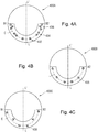
- Figs. 4A - 4C demonstratively show schematic diagrams of three types of distributed arrangement of light-emitting units.
- components such as the reflection cups and casing are omitted from figs. 4A - 4C .
- the VAD 400A comprises 6 light-emitting units which are symmetric with respect to a center line L-L'. These light-emitting units are arranged spaced apart from one another along a semicircular arc C.
- a light-emitting unit 432 is disposed close to a center point L of the semicircular arc.
- the light-emitting unit 432 has one LED chip.
- a light-emitting unit 436 is disposed close to an end-point (B1, B2) of the semicircular arc C.
- the light-emitting unit 436 has three LED chips.
- a light-emitting unit 434 located in a middle position has two LED chips.
- a reflection cup closer to an end-point of the semicircular arc C comprises a greater number of LED chips.
- Such a design cooperates with the reflection cup design, making it easier to make up light intensity distribution in a region close to the top surface of the optical coverage volume.
- the VAD 400B comprises 6 light-emitting units which are symmetric with respect to a center line L-L'. These light-emitting units are arranged spaced apart from one another along a semicircular arc C. Each light-emitting unit 435 comprises a single LED chip, and the gap between each pair of adjacent light-emitting units gradually increases from a center point L to an end-point.
- the VAD 400C comprises 6 light-emitting units which are symmetric with respect to a center line L-L'. These light-emitting units are arranged spaced apart from one another along a semicircular arc C. Each light-emitting unit 439 comprises a single LED chip, and the light-emitting units 439 are arranged in a staggered manner on two sides of the semicircular arc C.
- 6 reflection cups 25 as shown in figs. 2 and 3 are arranged in the shape of a semicircular ring, and a direction in which each reflection cup opens is arranged on the periphery of the semicircular ring.
- the 6 reflection cups 25 are symmetric with respect to the center line L-L'. Characteristics held in common by the reflection cups in the present invention are described below, taking as an example a reflection cup 251 close to the center point L in figs. 2 and 3 .
- Fig. 5 shows the specific structure of a reflection cup 251. As fig. 5 shows, the reflection cup 251 is arranged to partially surround the light-emitting unit 23, and an inner surface of the reflection cup is a reflective surface. In fig.
- the light-emitting unit 23 is two LED chips arranged side by side.
- the inner surface of the reflection cup is substantially a concave surface.
- the inner surface of the reflection cup may be one continuous curved surface, and may also comprise two or more secondary curved surfaces adjoining each other.
- part of a surface in the reflection cup could also be designed as a convex surface, as long as it can reflect light towards the optical coverage volume V.
- the reflection cup 251 has three main reflective parts 251_1, 251_3 and 251_5 which adjoin each other.
- the reflective part 251_1 faces the light-emitting unit 23, and is substantially a concave surface, extending on an inner periphery of a semicircular ring.
- Fig. 5B shows a partial section taken along M-M' in fig. 5A .
- the reflective part 251_1 1 can reflect light emitted by the light-emitting unit 23 towards the optical coverage volume V.
- the reflective part 251_1 may also specifically comprise e.g. three secondary reflective parts a, b and c, which adjoin each other.
- Each secondary reflective part extends in the direction of the inner periphery of the semicircular ring, and the different secondary reflective parts are stacked on top of one another.
- the three secondary reflective parts show slight differences in curvature and angle of inclination, in order to effectively reflect light which is incident at different angles.
- the reflective part 251_3 and the reflective part 251_5 are substantially opposite each other, with the light-emitting unit 23 being disposed between the reflective parts 251_3 and 251_5.
- the reflective parts 251_3 and 251_5 are both inclined in a direction away from the light-emitting unit 23, so as to reflect light emitted by the light-emitting unit 23 towards the optical coverage volume V thereof.
- the design of the reflective parts 251_3 and 251_5 can increase the light intensity distribution area of light outputted by the light-emitting unit 23, thereby making up the light intensity distribution in a region outside the range of linear illumination of the light-emitting unit 23; in other words, the two reflective parts can reflect a greater amount of the energy emitted by the light-emitting unit 23 in a designated direction (the optical coverage volume V) required by a standard.
- the reflection cup 251 is also provided with an auxiliary reflective part 251_7 on an edge located above the light-emitting unit 23.
- the auxiliary reflective part 251_7 is a concave surface extending in a circumferential direction. Preferably, one such concave surface is provided for each LED chip.
- the reflection cup 251 has an auxiliary reflective part 251_7 comprising two concave surfaces. The auxiliary reflective part 251_7 can enhance the light intensity distribution in a region close to the top surface of the optical coverage volume V.
- the reflection cup 251 also has a bottom surface 251_8.
- An opening 251_9 is also provided on the bottom surface 251_8; the light-emitting unit 23 is adapted to pass through the opening 251_9 and thereby expose a light-emitting surface thereof.
- the bottom surface is preferably also a reflective surface.
- the reflection cup could also not have a bottom surface, but be directly fixed to the support plate 21.
- the bottom surface 251_8 can subject stray light occurring in the reflection cup 251 to further reflection, in order to make effective use of the energy of the light-emitting unit.
- the presence of the bottom surface 251_8 can increase the sturdiness and durability of the overall structure of the 6 reflection cups arranged together.
- Figs. 2 and 3 are returned to below.
- the 6 reflection cups 250 in figs. 2 and 3 are symmetric with respect to the center line L-L', i.e. the symmetrical reflection cups on two sides of the center line have the same structure.
- the structures of the reflection cup 253 and the reflection cup 255 are substantially similar to the structure of the reflection cup 251. The difference is that the directions of inclination of two substantially opposite reflective parts 253_3 and 253_5 of the reflection cup 253 are different.
- the reflective part 253-3 close to an end B1 is inclined in a direction away from the light-emitting unit 23, whereas the reflective part 253_5 close to the center line is inclined towards the light-emitting unit.
- the reflective part 253_3 comprises three secondary reflective parts e, f and d which are stacked.
- the three secondary reflective parts are each conical curved surfaces; parameters such as curvature and direction of inclination thereof are different from one another.
- an area occupied by the secondary reflective part e is greater than the sum of the other two.
- the secondary reflective part e is inclined in a direction away from the light-emitting unit.
- the secondary reflective parts f and d are inclined towards the light-emitting unit.
- the reflective part 253_3 could also have one continuous reflective surface, or have 2, 4 or more secondary reflective parts.
- the reflective part 253_5 may be one continuous reflective curved surface, and could also be a surface having multiple secondary reflective surfaces.
- the design of the reflective part 253_3 of the reflection cup 253 makes it easier for light emitted by the light-emitting unit to be reflected in the direction of the end of the semicircular ring, to enhance light intensity distribution in a region close to the top surface of the optical coverage volume V.
- the directions of inclination of two substantially opposite reflective parts 255-3 and 255_5 of the reflection cup 255 in fig. 3 are different.
- the reflective part 255_3 close to an end B is inclined towards the light-emitting unit, whereas the reflective part 255_5 close to the center line is inclined in a direction away from the light-emitting unit.
- Such a design can cause more of the light emitted by the light-emitting unit in the reflection cup 255 to be reflected towards the end B.
- the reflective part 255_3 comprises three secondary reflective parts which are stacked.
- the three secondary reflective parts are each conical curved surfaces; parameters such as curvature and direction of inclination thereof are different from one another.
- the three secondary reflective parts have substantially equivalent areas.
- the reflective part 255_1 is a conical curved surface tending towards planarity.
- the reflective part 255_1 also preferably has two or more secondary reflective parts. As the reflective part 255_1 is a reflective surface tending towards planarity, it can reflect light in the direction of the vicinity of the end B more effectively, thereby enhancing the light intensity distribution in a region close to the top surface in the optical coverage volume.
- the transparent cover 27 and casing 29 have the function of protecting internal components of the VAD, and can enable light emitted by the VAD to be projected outwards.
- the discrete transparent cover 27 and casing 29 in fig. 3 may be replaced with a casing having a transparent window, or be replaced with a completely transparent casing; the transparent cover 27 may even be omitted, with the light-emitting units being exposed directly to the outside.
- the alarm device shown in fig. 3 is an acoustic/optical alarm device.
- the transparent cover 27 has a sound channel part 272. When the casing 29 is engaged with the transparent cover 27, a sound chamber is formed at the sound channel part 272.
- the use of an integrally formed element 27 can simultaneously realize the functions of a sound channel and an optically transparent cover, increasing the degree of integration of the entire product, and simplifying the processing steps.
- Fig. 6 demonstratively shows an alternative solution for the transparent cover 27.
- a transparent cover 67 is provided with at least one prism on a transparent part A thereof.
- each prism is positioned on an inner surface of the transparent cover 67.
- Fig. 6 demonstratively shows two prisms 673, each prism 673 extending in the circumferential direction of the transparent cover. The number of prisms 673 may also be increased or reduced as required.
- the inner surface of the transparent cover 67 may also be provided with a prism 675 as shown in fig. 6 .
- the prism 675 extends in a direction perpendicular to the circumferential direction.
- Figs. 7A - 7D demonstratively show a VAD according to another embodiment of the present invention.
- the VAD can achieve switching from an acoustic/optical alarm device (beacon and sounder) to an acoustic alarm device (sounder) by changing the casing.
- at least one of the reflection cup and the light-emitting unit is removable.
- Fig. 7A shows a perspective drawing of the casing 29 and transparent cover 27 in fig. 3 after being engaged with each other.
- the casing 29 has an opening in the form of a semicircular ring, and the transparent part A of the transparent cover 27 is exposed through the opening.
- Fig. 7B shows a partial section taken along M-M' in fig.
- FIG. 7A shows a partial sectional drawing of the acoustic alarm device, wherein the casing 79 completely covers the transparent cover 27, and no reflection cups 25 and no light-emitting units 23 are installed in the acoustic alarm device.
- two products namely an acoustic/optical alarm device and an acoustic alarm device, can be obtained with the same basic structure, with no need for excessive changes to be made.
- Such a design facilitates production and processing, and so lowers production costs.
Abstract
Description
- The present invention generally relates to a notification device for issuing an alert to indicate an emergency, and in particular relates to a visual notification device used in a fire protection system, also called a visual alarm device (VAD) or optical alarm device.
- Visual alarm devices are widely used in fire alarm systems, being used to send out a visible alarm indication, e.g. high-intensity strobe light, to on-site personnel when an emergency occurs. In general, a visual alarm device (VAD) is connected to a control apparatus (control panel) via a field line or a wireless link. When the occurrence of an emergency (e.g. a fire) is detected, the control apparatus can trigger the VAD via the field line, such that the VAD emits high-intensity alarm light visible to the human eye, to prompt on-site personnel to promptly evacuate a region of danger.
- In general, a VAD may be installed on a ceiling (abbreviated as "top-mounted" or on a wall (abbreviated as "wall-mounted").
Fig. 1 demonstratively shows a schematic diagram of a wall-mountedVAD 100. As shown infig. 1 , theVAD 100 is mounted on a wall W, and can illuminate a cubic space V that substantially has the shape of a cube or cuboid, wherein the VAD 100 is located at the mid-point of a top edge of the cubic space V. The light intensity distribution on the surfaces of this cubic space V must meet the requirements of the relevant fire protection standard. The cubic space V is generally described by (X, Y, Y), wherein X represents the mounting height of theVAD 100 from the floor, e.g. 2.4 m, and Y represents the furthest distance that can be reached by light from the VAD in the direction of a perpendicular wall surface, and the range that can be covered by light from the VAD in the direction of a parallel wall surface, e.g. Y = 10 m. Thus, the cubic space V is also called the optical coverage volume, which is also the space specified in the relevant fire protection standard as needing to be illuminated by alarm light. When the VAD 100 is actually mounted, the alarm effectiveness of the VAD can be guaranteed as long as the room in which it is mounted is smaller than the optical coverage volume V. - As light-emitting diode (LED) technology matures, LED chips are gradually being used as light sources in VADs. To meet the requirements of the relevant standard with respect to the VAD light intensity distribution, it is generally necessary to use a high-intensity LED chip, the power consumption of which is also high.
- For this reason, there is a need to propose a VAD using an LED chip as a light source, which VAD can lower the performance requirements for single LED chips while meeting the requirements of the relevant standard.
- An object of the present invention is to provide a visual alarm device (VAD) suitable for wall mounting, which can use LED chips with low power consumption as a light source.
- According to one aspect of the present invention, the present invention proposes an alarm device suitable for wall mounting, comprising: a support plate; at least three light-emitting units, which are disposed on the support plate and are arranged spaced apart from one another along a substantially semicircular arc; at least one reflection cup capable of being fixed to the support plate, each reflection cup being adapted to accommodate at least one of the light-emitting units, the reflection cup(s) substantially extending or being arranged in the shape of a semicircular ring, an inner surface of the reflection cup being a reflective surface and being constructed to reflect light emitted by the light-emitting unit towards a substantially cubic optical coverage volume, wherein an equivalent optical center of the alarm device is positioned in a center position on a top edge of the optical coverage volume.
- Preferably, if the alarm device comprises two or more reflection cups, two adjacent reflection cups space the light-emitting units in the two reflection cups apart from each other. Optionally, each pair of adjacent light-emitting units is spaced apart by an equal distance. Optionally, each pair of adjacent light-emitting units is spaced apart by a gradually changing distance. Optionally, each light-emitting unit comprises two or more LED chips.
- The alarm device described above uses multiple discrete light-emitting units, which are arranged spaced apart from one another substantially along a semicircular arc. When such a distributed arrangement is adopted, multiple light-emitting units can together make a contribution to the light intensity output of the alarm device; this lowers the requirement for light intensity output by each light-emitting unit. If necessary, multiple light-emitting units may also be arranged to provide a higher light flux, to achieve the objective of covering a larger space. Moreover, by disposing light-emitting units close to two end-points of a semicircular arc and having these cooperate with a reflecting structure such as reflection cups, the light intensity distribution close to the top surface of the optical coverage volume V can be improved, so that the requirements of the relevant standard can be met more easily. Thus, the example shown in
fig. 2 can use light-emitting units with lower power consumption, with a light intensity distribution capable of meeting standard requirements. In turn, the design of the reflection cups can reflect light emitted by each light-emitting unit towards the optical coverage volume. This design of reflection cup can also effectively meet the requirements set out in the relevant standard with regard to light intensity output of the alarm device in a designated direction, and effectively make up light intensity distribution. - Preferably, each reflection cup is arranged to partially surround at least one of the light-emitting units positioned therein, and a light output opening of the reflection cup is disposed on a periphery of the semicircular ring. Preferably, an inner surface of the reflection cup is a concave surface, the reflection cup has substantially opposite first and second reflective parts and the light-emitting unit is positioned between the first and second reflective parts, wherein at least one of the first and second reflective parts is inclined in a direction away from the light-emitting unit. The design of the first and second reflective parts can increase the light intensity distribution area of light outputted by the light-emitting unit, thereby making up the light intensity distribution in a region outside the range of linear illumination of the light-emitting unit. In other words, the two reflective parts can reflect a greater amount of the energy emitted by the light-emitting unit in a designated direction (the optical coverage volume V) required by a standard.
- Optionally, the first and second reflective parts of the reflection cup close to a center point of the semicircular ring are both inclined in a direction away from the light-emitting unit. Optionally, in the case of the reflection cup located in the vicinity of an end point of the semicircular ring, the first reflective part close to the end point of the semicircular ring is inclined towards the light-emitting unit, and the second reflective part is inclined away from the light-emitting unit.
- Preferably, the first reflective part or second reflective part of at least one reflection cup comprises two or more secondary reflective parts adjoining each other, each secondary reflective part being a reflective surface in the form of a conical curved surface. By using multiple secondary reflective surfaces, the curvature or orientation of the secondary reflective surfaces can be set more effectively for light that is incident at different angles, thereby increasing reflection efficiency.
- Preferably, each reflection cup further comprises a third reflective part, which adjoins the first and second reflective parts and faces the light-emitting unit accommodated in the reflection cup, the third reflective part being a concave surface. Preferably, the third reflective part comprises at least two secondary reflective parts adjoining each other, each secondary reflective part being a reflective surface in the form of a conical curved surface. Light emitted by the light-emitting part away from the optical coverage volume can be reflected towards the optical coverage volume by the third reflective part.
- Preferably, each reflection cup further comprises a first auxiliary reflective part disposed on an edge of the reflection cup above the light-emitting unit, the first auxiliary reflective part extending to form a concave surface; preferably, the first auxiliary reflective part has multiple concave surfaces corresponding in quantity and position to the LED chips. The auxiliary reflective part can enhance the light intensity distribution in a region close to the top surface of the optical coverage volume.
- Optionally, the alarm device further comprises a transparent cover, which at least covers the light-emitting units and the reflection cup, with at least one prism part being disposed on the transparent cover, the prism part being capable of guiding light emitted by the light-emitting unit so as to be scattered towards the optical coverage volume. Preferably, the at least one prism part comprises at least one prism part extending in the circumferential direction of the transparent cover, or comprises at least one prism part extending in a direction perpendicular to the circumferential direction of the transparent cover. By setting prisms on the transparent cover, the angle of spread of light emitted by the light-emitting units can be further expanded.
- Preferably, the alarm device further comprises a replaceable casing which can at least partially cover the transparent cover, with at least one of the light-emitting unit and the reflection cup being removable. Preferably, the replaceable casing is a first casing having a semicircular ring opening, the semicircular ring opening being adapted to expose the light-emitting units and the reflection cup. The replaceable casing may also be a casing which completely covers the transparent cover. By using a replaceable casing and a removable light-emitting unit or reflection cup, two products, namely an acoustic/optical alarm device and an acoustic alarm device, can be obtained with the same basic structure, with no need for excessive changes to be made. Such a design facilitates production and processing, and so lowers production costs.
- Preferred embodiments are explained below in a clear and easily comprehensible way with reference to the accompanying drawings, to further explain the abovementioned characteristics, technical features and advantages of the present invention and embodiments thereof.
- The accompanying drawings below merely illustrate and explain the present invention schematically, without limiting the scope thereof.
-
Fig. 1 demonstratively shows an optical coverage volume of a wall-mounted VAD. -
Fig. 2 shows a schematic diagram of a VAD according to an embodiment of the present invention. -
Fig. 3 shows a perspective exploded view of the VAD shown infig. 2 . -
Figs. 4A - 4C schematically show layout diagrams of light sources in a VAD according to another embodiment of the present invention. -
Figs. 5A and 5B show structural schematic diagrams of a reflection cup in a VAD according to an embodiment of the present invention. -
Fig. 6 shows a schematic diagram of a transparent cover in a VAD according to another embodiment of the present invention. -
Figs. 7A - 7D show schematic diagrams of a casing of a VAD according to another embodiment of the present invention. - To enable clearer understanding of the technical features, objectives and effects of the invention, particular embodiments of the present invention are now explained with reference to the accompanying drawings, in which identical labels indicate structurally identical components or components with similar structures but identical functions.
- As used herein, "schematic" means "serving as an instance, example or illustration". No drawing or embodiment described herein as "schematic" should be interpreted as a more preferred or more advantageous technical solution.
- To make the drawings appear uncluttered, only those parts relevant to the present invention are shown schematically in the drawings; they do not represent the actual structure thereof as a product. Furthermore, to make the drawings appear uncluttered for ease of understanding, in the case of components having the same structure or function in certain drawings, only one of these is drawn schematically, or only one is marked.
- In this text, "a" does not only mean "just this one"; it may also mean "more than one". Furthermore, as used herein, "first" and "second" etc. are merely used to differentiate between parts, not to indicate their order or degree of importance, etc.
-
Fig. 2 shows a wall-mountedVAD 200 according to an embodiment of the present invention.Fig. 3 demonstratively shows an exploded view of theVAD 200 shown infig. 2 . In the example offigs. 2 and3 , theVAD 200 comprises asupport plate 21, 6 light-emittingunits 23, 6 reflection cups 25, atransparent cover 27, and acasing 29. Here, to facilitate description, 25 refers to a general designation for the reflection cups, or refers to any one reflection cup. 25x (x = 1, 3, 5) refers to a single specific reflection cup. TheVAD 200 is mounted on a wall in the manner shown infig. 1 . In other words, an equivalent optical centre of theVAD 200 is positioned in a center position on a top edge of the optical coverage volume V. After mounting on the wall, a plane in which thesupport plate 21 of theVAD 200 lies is parallel to the wall surface W, and a transparent part A through which light can pass is oriented downward. - As shown in
figs. 2 and3 , the external form of theVAD 200 is substantially disk-shaped. However, the external form of the VAD is not limited to this, and could also be spherical, hemispherical, rectangular or ellipsoid, etc. Preferably, asfig. 3 shows, thetransparent cover 27 is a complete disk-shaped cover, which may be engaged with thesupport plate 21, thereby forming a chamber. The light-emittingunits 23 and reflection cups 25 are accommodated in the chamber. Thecasing 29 may be engaged with thetransparent cover 27. Thecasing 29 also has a substantiallysemi-annular opening 292; the transparent part A may be exposed through theopening 292, and exactly covers the light-emittingunits 23 and reflection cups 25. - In the example of
figs. 2 and3 , the 6 light-emittingunits 23 are disposed on thesupport plate 21. Thesupport plate 21 is preferably a drive circuit board, which can support the light-emittingunits 23 and can transmit a drive signal to each light-emittingunit 23. In this example, thesupport plate 21 is a main circuit board, which is substantially disk-shaped. Optionally, thesupport plate 21 may also be semi-annular, and is just used to position the light-emitting units. Preferably, thesupport plate 21 may also be a drive board of the light-emitting units, not a main circuit board. - The 6 light-emitting
units 23 are arranged spaced apart from one another along a semicircular arc C on thesupport plate 21. Preferably, the semicircular arc C is close to an edge of thesupport plate 21. Each light-emittingunit 23 may comprise one, two or more LED chips. In the example offigs. 2 and3 , each light-emittingunit 23 has two LED chips arranged side by side, and adjacent light-emittingunits 23 are spaced by substantially equal distances. Optionally, according to actual requirements, the number of light-emittingunits 23 may also be three, four or five or more. - In
fig. 2 , the 6 reflection cups 25 may be fixed to thesupport plate 21 and are arranged together to form a semicircular ring. Openings of the reflection cups are disposed on the periphery of the semicircular ring. Eachreflection cup 25 may accommodate one light-emittingunit 23. An inner surface of eachreflection cup 25 is designed as a reflective surface; these reflective surfaces can reflect light emitted by the light-emittingunits 23 towards an optical coverage volume V as shown infig. 1 , wherein theVAD 200 is disposed in a center position of a top edge of the optical coverage volume V. Optionally, infigs. 2 and3 , the number of reflection cups 25 may also be 1, 2, 3 or more. One, two or more light-emittingunits 23 may be accommodated in each reflection cup. In the case of two or more reflection cups, two adjacent reflection cups may space apart light-emitting units in each reflection cup. Preferably, the 6 reflection cups 25 infig. 3 are constructed as an integrally formedelement 26, which substantially extends in a semi-annular shape. - In the embodiment above, the
VAD 200 uses multiple discrete light-emitting units, which are arranged spaced apart from one another substantially along a semicircular arc. When such a distributed arrangement is adopted, multiple light-emitting units can together make a contribution to the light intensity output of the VAD; this lowers the requirement for light intensity output by each light-emitting unit. If necessary, multiple light-emitting units may also be arranged to provide a higher light flux, to achieve the objective of covering a larger space. Moreover, by disposing light-emitting units close to two end-points of a semicircular arc and having these cooperate with a reflecting structure such as reflection cups, the light intensity distribution close to the top surface of the optical coverage volume V can be improved, so that the requirements of the relevant standard can be met more easily. Thus, the example shown infig. 2 can use light-emitting units with lower power consumption, with a light intensity distribution capable of meeting standard requirements. In turn, the design of the reflection cups can reflect light emitted by each light-emitting unit towards the optical coverage volume V. This design of reflection cup can also effectively meet the requirements set out in the relevant standard with regard to light intensity output of the VAD in a designated direction, and effectively make up light intensity distribution. -
Figs. 4A - 4C demonstratively show schematic diagrams of three types of distributed arrangement of light-emitting units. For the sake of simplicity, components such as the reflection cups and casing are omitted fromfigs. 4A - 4C . Infig. 4A , theVAD 400A comprises 6 light-emitting units which are symmetric with respect to a center line L-L'. These light-emitting units are arranged spaced apart from one another along a semicircular arc C. For example, a light-emittingunit 432 is disposed close to a center point L of the semicircular arc. The light-emittingunit 432 has one LED chip. A light-emittingunit 436 is disposed close to an end-point (B1, B2) of the semicircular arc C. The light-emittingunit 436 has three LED chips. A light-emittingunit 434 located in a middle position has two LED chips. In other words, in the example offig. 4A , a reflection cup closer to an end-point of the semicircular arc C comprises a greater number of LED chips. Such a design cooperates with the reflection cup design, making it easier to make up light intensity distribution in a region close to the top surface of the optical coverage volume. - In
fig. 4B , theVAD 400B comprises 6 light-emitting units which are symmetric with respect to a center line L-L'. These light-emitting units are arranged spaced apart from one another along a semicircular arc C. Each light-emittingunit 435 comprises a single LED chip, and the gap between each pair of adjacent light-emitting units gradually increases from a center point L to an end-point. - In
fig. 4C , theVAD 400C comprises 6 light-emitting units which are symmetric with respect to a center line L-L'. These light-emitting units are arranged spaced apart from one another along a semicircular arc C. Each light-emittingunit 439 comprises a single LED chip, and the light-emittingunits 439 are arranged in a staggered manner on two sides of the semicircular arc C. - 6 reflection cups 25 as shown in
figs. 2 and3 are arranged in the shape of a semicircular ring, and a direction in which each reflection cup opens is arranged on the periphery of the semicircular ring. The 6 reflection cups 25 are symmetric with respect to the center line L-L'. Characteristics held in common by the reflection cups in the present invention are described below, taking as an example areflection cup 251 close to the center point L infigs. 2 and3 .Fig. 5 shows the specific structure of areflection cup 251. Asfig. 5 shows, thereflection cup 251 is arranged to partially surround the light-emittingunit 23, and an inner surface of the reflection cup is a reflective surface. Infig. 5 , the light-emittingunit 23 is two LED chips arranged side by side. Preferably, the inner surface of the reflection cup is substantially a concave surface. The inner surface of the reflection cup may be one continuous curved surface, and may also comprise two or more secondary curved surfaces adjoining each other. Optionally, part of a surface in the reflection cup could also be designed as a convex surface, as long as it can reflect light towards the optical coverage volume V. - As shown in
fig. 5A , thereflection cup 251 has three main reflective parts 251_1, 251_3 and 251_5 which adjoin each other. The reflective part 251_1 faces the light-emittingunit 23, and is substantially a concave surface, extending on an inner periphery of a semicircular ring.Fig. 5B shows a partial section taken along M-M' infig. 5A . The reflective part 251_1 1 can reflect light emitted by the light-emittingunit 23 towards the optical coverage volume V. Preferably, as shown infig. 5A , the reflective part 251_1 may also specifically comprise e.g. three secondary reflective parts a, b and c, which adjoin each other. Each secondary reflective part extends in the direction of the inner periphery of the semicircular ring, and the different secondary reflective parts are stacked on top of one another. The three secondary reflective parts (secondary reflective surfaces) show slight differences in curvature and angle of inclination, in order to effectively reflect light which is incident at different angles. - In the
reflection cup 251 shown infig. 5A , the reflective part 251_3 and the reflective part 251_5 are substantially opposite each other, with the light-emittingunit 23 being disposed between the reflective parts 251_3 and 251_5. As shown infig. 5A , the reflective parts 251_3 and 251_5 are both inclined in a direction away from the light-emittingunit 23, so as to reflect light emitted by the light-emittingunit 23 towards the optical coverage volume V thereof. The design of the reflective parts 251_3 and 251_5 can increase the light intensity distribution area of light outputted by the light-emittingunit 23, thereby making up the light intensity distribution in a region outside the range of linear illumination of the light-emittingunit 23; in other words, the two reflective parts can reflect a greater amount of the energy emitted by the light-emittingunit 23 in a designated direction (the optical coverage volume V) required by a standard. - Preferably, to guarantee light intensity distribution in a region close to the top surface of the optical coverage volume V, the
reflection cup 251 is also provided with an auxiliary reflective part 251_7 on an edge located above the light-emittingunit 23. The auxiliary reflective part 251_7 is a concave surface extending in a circumferential direction. Preferably, one such concave surface is provided for each LED chip. In the example offig. 5A , thereflection cup 251 has an auxiliary reflective part 251_7 comprising two concave surfaces. The auxiliary reflective part 251_7 can enhance the light intensity distribution in a region close to the top surface of the optical coverage volume V. - In the example of
fig. 5A , thereflection cup 251 also has a bottom surface 251_8. An opening 251_9 is also provided on the bottom surface 251_8; the light-emittingunit 23 is adapted to pass through the opening 251_9 and thereby expose a light-emitting surface thereof. The bottom surface is preferably also a reflective surface. Optionally, the reflection cup could also not have a bottom surface, but be directly fixed to thesupport plate 21. On the one hand, the bottom surface 251_8 can subject stray light occurring in thereflection cup 251 to further reflection, in order to make effective use of the energy of the light-emitting unit. On the other hand, the presence of the bottom surface 251_8 can increase the sturdiness and durability of the overall structure of the 6 reflection cups arranged together. -
Figs. 2 and3 are returned to below. The 6 reflection cups 250 infigs. 2 and3 are symmetric with respect to the center line L-L', i.e. the symmetrical reflection cups on two sides of the center line have the same structure. The structures of thereflection cup 253 and thereflection cup 255 are substantially similar to the structure of thereflection cup 251. The difference is that the directions of inclination of two substantially opposite reflective parts 253_3 and 253_5 of thereflection cup 253 are different. The reflective part 253-3 close to an end B1 is inclined in a direction away from the light-emittingunit 23, whereas the reflective part 253_5 close to the center line is inclined towards the light-emitting unit. Such a design can cause more of the light emitted by the light-emitting unit in thereflection cup 253 to be reflected towards the end B. More preferably, the reflective part 253_3 comprises three secondary reflective parts e, f and d which are stacked. The three secondary reflective parts are each conical curved surfaces; parameters such as curvature and direction of inclination thereof are different from one another. Preferably, an area occupied by the secondary reflective part e is greater than the sum of the other two. The secondary reflective part e is inclined in a direction away from the light-emitting unit. The secondary reflective parts f and d are inclined towards the light-emitting unit. Optionally, the reflective part 253_3 could also have one continuous reflective surface, or have 2, 4 or more secondary reflective parts. As shown infig. 3 , the reflective part 253_5 may be one continuous reflective curved surface, and could also be a surface having multiple secondary reflective surfaces. The design of the reflective part 253_3 of thereflection cup 253 makes it easier for light emitted by the light-emitting unit to be reflected in the direction of the end of the semicircular ring, to enhance light intensity distribution in a region close to the top surface of the optical coverage volume V. - Unlike the
reflection cup 251 infig. 5A , the directions of inclination of two substantially opposite reflective parts 255-3 and 255_5 of thereflection cup 255 infig. 3 are different. The reflective part 255_3 close to an end B is inclined towards the light-emitting unit, whereas the reflective part 255_5 close to the center line is inclined in a direction away from the light-emitting unit. Such a design can cause more of the light emitted by the light-emitting unit in thereflection cup 255 to be reflected towards the end B. More preferably, the reflective part 255_3 comprises three secondary reflective parts which are stacked. The three secondary reflective parts are each conical curved surfaces; parameters such as curvature and direction of inclination thereof are different from one another. Preferably, the three secondary reflective parts have substantially equivalent areas. Preferably, in thereflection cup 255, the reflective part 255_1 is a conical curved surface tending towards planarity. The reflective part 255_1 also preferably has two or more secondary reflective parts. As the reflective part 255_1 is a reflective surface tending towards planarity, it can reflect light in the direction of the vicinity of the end B more effectively, thereby enhancing the light intensity distribution in a region close to the top surface in the optical coverage volume. - Referring to
fig. 3 , thetransparent cover 27 andcasing 29 have the function of protecting internal components of the VAD, and can enable light emitted by the VAD to be projected outwards. Optionally, the discretetransparent cover 27 andcasing 29 infig. 3 may be replaced with a casing having a transparent window, or be replaced with a completely transparent casing; thetransparent cover 27 may even be omitted, with the light-emitting units being exposed directly to the outside. Preferably, the alarm device shown infig. 3 is an acoustic/optical alarm device. Thetransparent cover 27 has asound channel part 272. When thecasing 29 is engaged with thetransparent cover 27, a sound chamber is formed at thesound channel part 272. Thus, the use of an integrally formedelement 27 can simultaneously realize the functions of a sound channel and an optically transparent cover, increasing the degree of integration of the entire product, and simplifying the processing steps. -
Fig. 6 demonstratively shows an alternative solution for thetransparent cover 27. As shown infig. 6 , atransparent cover 67 is provided with at least one prism on a transparent part A thereof. In the example offig. 6 , each prism is positioned on an inner surface of thetransparent cover 67.Fig. 6 demonstratively shows twoprisms 673, eachprism 673 extending in the circumferential direction of the transparent cover. The number ofprisms 673 may also be increased or reduced as required. Preferably, the inner surface of thetransparent cover 67 may also be provided with aprism 675 as shown infig. 6 . Theprism 675 extends in a direction perpendicular to the circumferential direction. By providing prisms on the transparent cover, the angle of spread of light emitted by a single light source can be expanded effectively, thereby improving the light intensity distribution of the VAD. -
Figs. 7A - 7D demonstratively show a VAD according to another embodiment of the present invention. The VAD can achieve switching from an acoustic/optical alarm device (beacon and sounder) to an acoustic alarm device (sounder) by changing the casing. In this embodiment, at least one of the reflection cup and the light-emitting unit is removable.Fig. 7A shows a perspective drawing of thecasing 29 andtransparent cover 27 infig. 3 after being engaged with each other. As shown infig. 7A , thecasing 29 has an opening in the form of a semicircular ring, and the transparent part A of thetransparent cover 27 is exposed through the opening.Fig. 7B shows a partial section taken along M-M' infig. 7A . Asfig. 7B shows, thetransparent cover 27 covers the light-emittingunits 23 and the reflection cups 25. Thecasing 29 is engaged with thetransparent cover 27. Aprotrusion 278 is provided on thetransparent cover 27, and exactly blocks a gap between thecasing 29 and thetransparent cover 27. By replacing thecasing 29 infigs. 7A and 7B with acomplete disk casing 79, and removing the reflection cups 25, an acoustic alarm device as shown infig. 7C can be obtained.Fig. 7D shows a partial sectional drawing of the acoustic alarm device, wherein thecasing 79 completely covers thetransparent cover 27, and no reflection cups 25 and no light-emittingunits 23 are installed in the acoustic alarm device. Thus, two products, namely an acoustic/optical alarm device and an acoustic alarm device, can be obtained with the same basic structure, with no need for excessive changes to be made. Such a design facilitates production and processing, and so lowers production costs. - It should be understood that although the description herein is based on various embodiments, it is by no means the case that each embodiment contains just one independent technical solution. Such a method of presentation is adopted herein purely for the sake of clarity. Those skilled in the art should consider the description in its entirety. The technical solutions in the various embodiments could also be suitably combined to form other embodiments capable of being understood by those skilled in the art.
- The series of detailed explanations set out above are merely particular explanations of feasible embodiments of the present invention, which are not intended to limit the scope of protection thereof. All equivalent embodiments or changes made without departing from the artistic spirit of the present invention, such as combinations, divisions or repetitions of features, shall be included in the scope of protection of the present invention.
Claims (15)
- An alarm device suitable for wall mounting, comprising:a support plate (21);at least three light-emitting units (23), which are disposed on the support plate (21) and are arranged spaced apart from one another along a substantially semicircular arc (C);at least one reflection cup (25) capable of being fixed to the support plate (21), each reflection cup being adapted to accommodate at least one of the light-emitting units (23), the reflection cup(s) (25) substantially extending or being arranged in the shape of a semicircular ring, an inner surface of the reflection cup being a reflective surface and being constructed to reflect light emitted by the light-emitting unit towards a substantially cubic optical coverage volume (V), wherein an equivalent optical center of the alarm device is positioned in a center position on a top edge of the optical coverage volume (V).
- The alarm device as claimed in claim 1, wherein two adjacent reflection cups (25) space the light-emitting units (23) in the two reflection cups apart from each other.
- The alarm device as claimed in claim 1 or 2, wherein each pair of adjacent light-emitting units (23) is spaced apart by an equal distance.
- The alarm device as claimed in claim 1 or 2, wherein each pair of adjacent light-emitting units (23) is spaced apart by a gradually changing distance.
- The alarm device as claimed in any one of claims 1 - 4, wherein each light-emitting unit (23) comprises two or more LED chips.
- The alarm device as claimed in any one of claims 1 - 5, wherein each reflection cup (25) is arranged to partially surround at least one of the light-emitting units (23) positioned therein, and a light output opening of the reflection cup (25) is disposed on a periphery of the semicircular ring.
- The alarm device as claimed in any one of claims 1 - 6, wherein an inner surface of the reflection cup (25) is a concave surface, the reflection cup has substantially opposite first and second reflective parts (251_3, 251_5) and the light-emitting unit (23) is positioned between the first and second reflective parts (251_3, 251_5), wherein at least one of the first and second reflective parts is inclined in a direction away from the light-emitting unit (23).
- The alarm device as claimed in claim 7, wherein the first and second reflective parts (251_3, 251_5) of the reflection cup (251) close to a center point (L) of the semicircular ring are both inclined in a direction away from the light-emitting unit (23).
- The alarm device as claimed in claim 7, wherein in the case of the reflection cup (255) located in the vicinity of an end point (B1, B2) of the semicircular ring, the first reflective part (255_3) close to the end point (B1, B2) of the semicircular ring is inclined towards the light-emitting unit (23), and the second reflective part (255_5) is inclined away from the light-emitting unit (23).
- The alarm device as claimed in any one of claims 7 - 9, wherein the first reflective part or second reflective part of at least one reflection cup comprises two or more secondary reflective parts (e, f, d) adjoining each other, each secondary reflective part being a reflective surface in the form of a conical curved surface.
- The alarm device as claimed in any one of claims 1 - 10, wherein each reflection cup (25) further comprises a third reflective part (251_1), which adjoins the first and second reflective parts (251_3, 251_5) and faces the light-emitting unit (23) accommodated in the reflection cup (25), the third reflective part being a concave surface.
- The alarm device as claimed in claim 11, wherein the third reflective part (251_1) comprises at least two secondary reflective parts (a, b, c) adjoining each other, each secondary reflective part being a reflective surface in the form of a conical curved surface.
- The alarm device as claimed in any one of claims 1 - 12, wherein each reflection cup (25) further comprises a first auxiliary reflective part (251_7) disposed on an edge of the reflection cup above the light-emitting unit, the first auxiliary reflective part extending to form a concave surface; preferably, the first auxiliary reflective part has multiple concave surfaces corresponding in quantity and position to the LED chips.
- The alarm device as claimed in any one of claims 1 - 13, further comprising a transparent cover (27), which at least covers the light-emitting units (23) and the reflection cup (25), with at least one prism part (673, 675) being disposed on the transparent cover, the prism part being capable of guiding light emitted by the light-emitting unit so as to be scattered towards the optical coverage volume (V); preferably, the at least one prism part comprises at least one prism part (673) extending in the circumferential direction of the transparent cover (67), or at least one prism part (675) extending in a direction perpendicular to the circumferential direction of the transparent cover (67).
- The alarm device as claimed in any one of claims 1 - 14, further comprising a replaceable casing (29, 79) which at least partially covers the transparent cover (27), with at least one of the light-emitting unit and the reflection cup being removable; preferably, the replaceable casing is a first casing (29) having a semicircular ring opening, the semicircular ring opening being adapted to expose the light-emitting units and the reflection cup, or the replaceable casing is a casing (79) which completely covers the transparent cover.
Priority Applications (1)
| Application Number | Priority Date | Filing Date | Title |
|---|---|---|---|
| PL17198285T PL3321898T3 (en) | 2016-11-11 | 2017-10-25 | Alarm device |
Applications Claiming Priority (1)
| Application Number | Priority Date | Filing Date | Title |
|---|---|---|---|
| CN201611001936.1A CN108074359B (en) | 2016-11-11 | 2016-11-11 | Alarm device |
Publications (2)
| Publication Number | Publication Date |
|---|---|
| EP3321898A1 true EP3321898A1 (en) | 2018-05-16 |
| EP3321898B1 EP3321898B1 (en) | 2019-09-18 |
Family
ID=60186082
Family Applications (1)
| Application Number | Title | Priority Date | Filing Date |
|---|---|---|---|
| EP17198285.3A Active EP3321898B1 (en) | 2016-11-11 | 2017-10-25 | Alarm device |
Country Status (3)
| Country | Link |
|---|---|
| EP (1) | EP3321898B1 (en) |
| CN (1) | CN108074359B (en) |
| PL (1) | PL3321898T3 (en) |
Cited By (1)
| Publication number | Priority date | Publication date | Assignee | Title |
|---|---|---|---|---|
| EP4332930A1 (en) * | 2022-08-01 | 2024-03-06 | Urmet S.P.A. | Optical signaling device for fire alarm systems |
Citations (5)
| Publication number | Priority date | Publication date | Assignee | Title |
|---|---|---|---|---|
| US6739738B1 (en) * | 2003-01-28 | 2004-05-25 | Whelen Engineering Company, Inc. | Method and apparatus for light redistribution by internal reflection |
| US20040218391A1 (en) * | 1999-11-29 | 2004-11-04 | Procter Jeffrey K. | Light emitting diode reflector |
| CN202938198U (en) * | 2012-12-11 | 2013-05-15 | 温州奥乐安全器材有限公司 | Alarm lamp for special vehicle |
| CN203442529U (en) * | 2013-08-13 | 2014-02-19 | 广州市佛达信号设备有限公司 | LED alarm lamp having optical mode of rotating light |
| US20140268753A1 (en) * | 2013-03-15 | 2014-09-18 | Walter Kidde Portable Equipment Inc. | Alarm with reflector ring |
Family Cites Families (3)
| Publication number | Priority date | Publication date | Assignee | Title |
|---|---|---|---|---|
| JPH11162209A (en) * | 1997-11-21 | 1999-06-18 | Yakku Kk | Lamp and automobile luminaire and light scattering member used therefor |
| CN101839410B (en) * | 2010-04-15 | 2012-05-09 | 北京朗波尔光电股份有限公司 | Space omnidirectional light-emitting diode (LED) |
| CN102818212A (en) * | 2012-08-24 | 2012-12-12 | 张文虎 | Light tower |
-
2016
- 2016-11-11 CN CN201611001936.1A patent/CN108074359B/en active Active
-
2017
- 2017-10-25 EP EP17198285.3A patent/EP3321898B1/en active Active
- 2017-10-25 PL PL17198285T patent/PL3321898T3/en unknown
Patent Citations (5)
| Publication number | Priority date | Publication date | Assignee | Title |
|---|---|---|---|---|
| US20040218391A1 (en) * | 1999-11-29 | 2004-11-04 | Procter Jeffrey K. | Light emitting diode reflector |
| US6739738B1 (en) * | 2003-01-28 | 2004-05-25 | Whelen Engineering Company, Inc. | Method and apparatus for light redistribution by internal reflection |
| CN202938198U (en) * | 2012-12-11 | 2013-05-15 | 温州奥乐安全器材有限公司 | Alarm lamp for special vehicle |
| US20140268753A1 (en) * | 2013-03-15 | 2014-09-18 | Walter Kidde Portable Equipment Inc. | Alarm with reflector ring |
| CN203442529U (en) * | 2013-08-13 | 2014-02-19 | 广州市佛达信号设备有限公司 | LED alarm lamp having optical mode of rotating light |
Cited By (1)
| Publication number | Priority date | Publication date | Assignee | Title |
|---|---|---|---|---|
| EP4332930A1 (en) * | 2022-08-01 | 2024-03-06 | Urmet S.P.A. | Optical signaling device for fire alarm systems |
Also Published As
| Publication number | Publication date |
|---|---|
| PL3321898T3 (en) | 2020-03-31 |
| CN108074359B (en) | 2020-12-04 |
| CN108074359A (en) | 2018-05-25 |
| EP3321898B1 (en) | 2019-09-18 |
Similar Documents
| Publication | Publication Date | Title |
|---|---|---|
| EP2711615A1 (en) | Lens and light emitting device incorporating a lens | |
| US8459860B2 (en) | Light flux controlling member, light-emitting device and lighting device | |
| US7597453B2 (en) | Luminaires using multiple quasi-point sources for unified radially distributed illumination | |
| JP5375966B2 (en) | Surface light source device, liquid crystal display device, and lens | |
| JP2010500735A (en) | Lighting device | |
| US8591079B2 (en) | LED ceiling lamp | |
| US9459397B2 (en) | Edge lit lighting device | |
| US20120224369A1 (en) | Lighting fixture with controlled photometric light emission | |
| US9858772B2 (en) | Lens, light-emitting device having the lens, and visual notification appliance | |
| JP2011029168A (en) | Reflection cover and lighting device employing the same | |
| JP5879548B2 (en) | Lighting device | |
| US3258590A (en) | Plates for light control | |
| EP1798467A1 (en) | Projection lighting device | |
| EP3321898B1 (en) | Alarm device | |
| JP7130913B2 (en) | Optical and lighting equipment | |
| JP5312287B2 (en) | LED lighting device | |
| US8624746B2 (en) | Wait staff signaling apparatus with high visibility indicators | |
| US8297789B2 (en) | Emergency exit indicator incorporating LED unit | |
| US10133029B2 (en) | Lens and light source apparatus | |
| CA2476644C (en) | Led signal with side emitting status indicators | |
| US20170268747A1 (en) | LED Optic for Offset Beam Generation | |
| JP2004302028A (en) | Display device and guiding light device | |
| CN202691604U (en) | Portable lighting device | |
| EP3483500B1 (en) | Multiple lighting safety device | |
| JP7187857B2 (en) | lighting fixtures and lenses |
Legal Events
| Date | Code | Title | Description |
|---|---|---|---|
| PUAI | Public reference made under article 153(3) epc to a published international application that has entered the european phase |
Free format text: ORIGINAL CODE: 0009012 |
|
| STAA | Information on the status of an ep patent application or granted ep patent |
Free format text: STATUS: THE APPLICATION HAS BEEN PUBLISHED |
|
| AK | Designated contracting states |
Kind code of ref document: A1 Designated state(s): AL AT BE BG CH CY CZ DE DK EE ES FI FR GB GR HR HU IE IS IT LI LT LU LV MC MK MT NL NO PL PT RO RS SE SI SK SM TR |
|
| AX | Request for extension of the european patent |
Extension state: BA ME |
|
| STAA | Information on the status of an ep patent application or granted ep patent |
Free format text: STATUS: REQUEST FOR EXAMINATION WAS MADE |
|
| 17P | Request for examination filed |
Effective date: 20181105 |
|
| RBV | Designated contracting states (corrected) |
Designated state(s): AL AT BE BG CH CY CZ DE DK EE ES FI FR GB GR HR HU IE IS IT LI LT LU LV MC MK MT NL NO PL PT RO RS SE SI SK SM TR |
|
| GRAP | Despatch of communication of intention to grant a patent |
Free format text: ORIGINAL CODE: EPIDOSNIGR1 |
|
| STAA | Information on the status of an ep patent application or granted ep patent |
Free format text: STATUS: GRANT OF PATENT IS INTENDED |
|
| INTG | Intention to grant announced |
Effective date: 20190515 |
|
| GRAS | Grant fee paid |
Free format text: ORIGINAL CODE: EPIDOSNIGR3 |
|
| GRAA | (expected) grant |
Free format text: ORIGINAL CODE: 0009210 |
|
| STAA | Information on the status of an ep patent application or granted ep patent |
Free format text: STATUS: THE PATENT HAS BEEN GRANTED |
|
| AK | Designated contracting states |
Kind code of ref document: B1 Designated state(s): AL AT BE BG CH CY CZ DE DK EE ES FI FR GB GR HR HU IE IS IT LI LT LU LV MC MK MT NL NO PL PT RO RS SE SI SK SM TR |
|
| REG | Reference to a national code |
Ref country code: GB Ref legal event code: FG4D |
|
| REG | Reference to a national code |
Ref country code: CH Ref legal event code: EP Ref country code: CH Ref legal event code: NV Representative=s name: SIEMENS SCHWEIZ AG, CH |
|
| REG | Reference to a national code |
Ref country code: DE Ref legal event code: R096 Ref document number: 602017007141 Country of ref document: DE |
|
| REG | Reference to a national code |
Ref country code: AT Ref legal event code: REF Ref document number: 1182223 Country of ref document: AT Kind code of ref document: T Effective date: 20191015 |
|
| REG | Reference to a national code |
Ref country code: IE Ref legal event code: FG4D |
|
| REG | Reference to a national code |
Ref country code: NL Ref legal event code: FP |
|
| REG | Reference to a national code |
Ref country code: SE Ref legal event code: TRGR |
|
| PG25 | Lapsed in a contracting state [announced via postgrant information from national office to epo] |
Ref country code: FI Free format text: LAPSE BECAUSE OF FAILURE TO SUBMIT A TRANSLATION OF THE DESCRIPTION OR TO PAY THE FEE WITHIN THE PRESCRIBED TIME-LIMIT Effective date: 20190918 Ref country code: BG Free format text: LAPSE BECAUSE OF FAILURE TO SUBMIT A TRANSLATION OF THE DESCRIPTION OR TO PAY THE FEE WITHIN THE PRESCRIBED TIME-LIMIT Effective date: 20191218 Ref country code: HR Free format text: LAPSE BECAUSE OF FAILURE TO SUBMIT A TRANSLATION OF THE DESCRIPTION OR TO PAY THE FEE WITHIN THE PRESCRIBED TIME-LIMIT Effective date: 20190918 Ref country code: NO Free format text: LAPSE BECAUSE OF FAILURE TO SUBMIT A TRANSLATION OF THE DESCRIPTION OR TO PAY THE FEE WITHIN THE PRESCRIBED TIME-LIMIT Effective date: 20191218 Ref country code: LT Free format text: LAPSE BECAUSE OF FAILURE TO SUBMIT A TRANSLATION OF THE DESCRIPTION OR TO PAY THE FEE WITHIN THE PRESCRIBED TIME-LIMIT Effective date: 20190918 |
|
| REG | Reference to a national code |
Ref country code: LT Ref legal event code: MG4D |
|
| PG25 | Lapsed in a contracting state [announced via postgrant information from national office to epo] |
Ref country code: LV Free format text: LAPSE BECAUSE OF FAILURE TO SUBMIT A TRANSLATION OF THE DESCRIPTION OR TO PAY THE FEE WITHIN THE PRESCRIBED TIME-LIMIT Effective date: 20190918 Ref country code: GR Free format text: LAPSE BECAUSE OF FAILURE TO SUBMIT A TRANSLATION OF THE DESCRIPTION OR TO PAY THE FEE WITHIN THE PRESCRIBED TIME-LIMIT Effective date: 20191219 Ref country code: AL Free format text: LAPSE BECAUSE OF FAILURE TO SUBMIT A TRANSLATION OF THE DESCRIPTION OR TO PAY THE FEE WITHIN THE PRESCRIBED TIME-LIMIT Effective date: 20190918 Ref country code: RS Free format text: LAPSE BECAUSE OF FAILURE TO SUBMIT A TRANSLATION OF THE DESCRIPTION OR TO PAY THE FEE WITHIN THE PRESCRIBED TIME-LIMIT Effective date: 20190918 |
|
| PG25 | Lapsed in a contracting state [announced via postgrant information from national office to epo] |
Ref country code: EE Free format text: LAPSE BECAUSE OF FAILURE TO SUBMIT A TRANSLATION OF THE DESCRIPTION OR TO PAY THE FEE WITHIN THE PRESCRIBED TIME-LIMIT Effective date: 20190918 Ref country code: RO Free format text: LAPSE BECAUSE OF FAILURE TO SUBMIT A TRANSLATION OF THE DESCRIPTION OR TO PAY THE FEE WITHIN THE PRESCRIBED TIME-LIMIT Effective date: 20190918 Ref country code: ES Free format text: LAPSE BECAUSE OF FAILURE TO SUBMIT A TRANSLATION OF THE DESCRIPTION OR TO PAY THE FEE WITHIN THE PRESCRIBED TIME-LIMIT Effective date: 20190918 Ref country code: PT Free format text: LAPSE BECAUSE OF FAILURE TO SUBMIT A TRANSLATION OF THE DESCRIPTION OR TO PAY THE FEE WITHIN THE PRESCRIBED TIME-LIMIT Effective date: 20200120 |
|
| PG25 | Lapsed in a contracting state [announced via postgrant information from national office to epo] |
Ref country code: SK Free format text: LAPSE BECAUSE OF FAILURE TO SUBMIT A TRANSLATION OF THE DESCRIPTION OR TO PAY THE FEE WITHIN THE PRESCRIBED TIME-LIMIT Effective date: 20190918 Ref country code: CZ Free format text: LAPSE BECAUSE OF FAILURE TO SUBMIT A TRANSLATION OF THE DESCRIPTION OR TO PAY THE FEE WITHIN THE PRESCRIBED TIME-LIMIT Effective date: 20190918 Ref country code: SM Free format text: LAPSE BECAUSE OF FAILURE TO SUBMIT A TRANSLATION OF THE DESCRIPTION OR TO PAY THE FEE WITHIN THE PRESCRIBED TIME-LIMIT Effective date: 20190918 Ref country code: IS Free format text: LAPSE BECAUSE OF FAILURE TO SUBMIT A TRANSLATION OF THE DESCRIPTION OR TO PAY THE FEE WITHIN THE PRESCRIBED TIME-LIMIT Effective date: 20200224 |
|
| REG | Reference to a national code |
Ref country code: DE Ref legal event code: R097 Ref document number: 602017007141 Country of ref document: DE |
|
| PLBE | No opposition filed within time limit |
Free format text: ORIGINAL CODE: 0009261 |
|
| STAA | Information on the status of an ep patent application or granted ep patent |
Free format text: STATUS: NO OPPOSITION FILED WITHIN TIME LIMIT |
|
| PG2D | Information on lapse in contracting state deleted |
Ref country code: IS |
|
| PG25 | Lapsed in a contracting state [announced via postgrant information from national office to epo] |
Ref country code: DK Free format text: LAPSE BECAUSE OF FAILURE TO SUBMIT A TRANSLATION OF THE DESCRIPTION OR TO PAY THE FEE WITHIN THE PRESCRIBED TIME-LIMIT Effective date: 20190918 Ref country code: LU Free format text: LAPSE BECAUSE OF NON-PAYMENT OF DUE FEES Effective date: 20191025 Ref country code: IS Free format text: LAPSE BECAUSE OF FAILURE TO SUBMIT A TRANSLATION OF THE DESCRIPTION OR TO PAY THE FEE WITHIN THE PRESCRIBED TIME-LIMIT Effective date: 20200119 |
|
| REG | Reference to a national code |
Ref country code: BE Ref legal event code: MM Effective date: 20191031 |
|
| 26N | No opposition filed |
Effective date: 20200619 |
|
| PG25 | Lapsed in a contracting state [announced via postgrant information from national office to epo] |
Ref country code: BE Free format text: LAPSE BECAUSE OF NON-PAYMENT OF DUE FEES Effective date: 20191031 Ref country code: MC Free format text: LAPSE BECAUSE OF FAILURE TO SUBMIT A TRANSLATION OF THE DESCRIPTION OR TO PAY THE FEE WITHIN THE PRESCRIBED TIME-LIMIT Effective date: 20190918 Ref country code: SI Free format text: LAPSE BECAUSE OF FAILURE TO SUBMIT A TRANSLATION OF THE DESCRIPTION OR TO PAY THE FEE WITHIN THE PRESCRIBED TIME-LIMIT Effective date: 20190918 |
|
| PG25 | Lapsed in a contracting state [announced via postgrant information from national office to epo] |
Ref country code: IE Free format text: LAPSE BECAUSE OF NON-PAYMENT OF DUE FEES Effective date: 20191025 |
|
| PG25 | Lapsed in a contracting state [announced via postgrant information from national office to epo] |
Ref country code: CY Free format text: LAPSE BECAUSE OF FAILURE TO SUBMIT A TRANSLATION OF THE DESCRIPTION OR TO PAY THE FEE WITHIN THE PRESCRIBED TIME-LIMIT Effective date: 20190918 |
|
| PG25 | Lapsed in a contracting state [announced via postgrant information from national office to epo] |
Ref country code: LI Free format text: LAPSE BECAUSE OF FAILURE TO SUBMIT A TRANSLATION OF THE DESCRIPTION OR TO PAY THE FEE WITHIN THE PRESCRIBED TIME-LIMIT Effective date: 20201031 Ref country code: CH Free format text: LAPSE BECAUSE OF FAILURE TO SUBMIT A TRANSLATION OF THE DESCRIPTION OR TO PAY THE FEE WITHIN THE PRESCRIBED TIME-LIMIT Effective date: 20201031 |
|
| PG25 | Lapsed in a contracting state [announced via postgrant information from national office to epo] |
Ref country code: MT Free format text: LAPSE BECAUSE OF FAILURE TO SUBMIT A TRANSLATION OF THE DESCRIPTION OR TO PAY THE FEE WITHIN THE PRESCRIBED TIME-LIMIT Effective date: 20190918 Ref country code: HU Free format text: LAPSE BECAUSE OF FAILURE TO SUBMIT A TRANSLATION OF THE DESCRIPTION OR TO PAY THE FEE WITHIN THE PRESCRIBED TIME-LIMIT; INVALID AB INITIO Effective date: 20171025 |
|
| PG25 | Lapsed in a contracting state [announced via postgrant information from national office to epo] |
Ref country code: TR Free format text: LAPSE BECAUSE OF FAILURE TO SUBMIT A TRANSLATION OF THE DESCRIPTION OR TO PAY THE FEE WITHIN THE PRESCRIBED TIME-LIMIT Effective date: 20190918 |
|
| PG25 | Lapsed in a contracting state [announced via postgrant information from national office to epo] |
Ref country code: MK Free format text: LAPSE BECAUSE OF FAILURE TO SUBMIT A TRANSLATION OF THE DESCRIPTION OR TO PAY THE FEE WITHIN THE PRESCRIBED TIME-LIMIT Effective date: 20190918 |
|
| PGFP | Annual fee paid to national office [announced via postgrant information from national office to epo] |
Ref country code: PL Payment date: 20221017 Year of fee payment: 6 |
|
| REG | Reference to a national code |
Ref country code: AT Ref legal event code: UEP Ref document number: 1182223 Country of ref document: AT Kind code of ref document: T Effective date: 20190918 |
|
| PGFP | Annual fee paid to national office [announced via postgrant information from national office to epo] |
Ref country code: CH Payment date: 20230201 Year of fee payment: 6 |
|
| P01 | Opt-out of the competence of the unified patent court (upc) registered |
Effective date: 20230523 |
|
| PGFP | Annual fee paid to national office [announced via postgrant information from national office to epo] |
Ref country code: NL Payment date: 20231009 Year of fee payment: 7 |
|
| PGFP | Annual fee paid to national office [announced via postgrant information from national office to epo] |
Ref country code: GB Payment date: 20231106 Year of fee payment: 7 |
|
| PGFP | Annual fee paid to national office [announced via postgrant information from national office to epo] |
Ref country code: SE Payment date: 20231010 Year of fee payment: 7 Ref country code: IT Payment date: 20231025 Year of fee payment: 7 Ref country code: FR Payment date: 20231017 Year of fee payment: 7 Ref country code: DE Payment date: 20231214 Year of fee payment: 7 Ref country code: AT Payment date: 20230911 Year of fee payment: 7 |
|
| PGFP | Annual fee paid to national office [announced via postgrant information from national office to epo] |
Ref country code: PL Payment date: 20231013 Year of fee payment: 7 |