EP3321886A1 - Spectral ct image reconstructing method and spectral ct imaging system - Google Patents
Spectral ct image reconstructing method and spectral ct imaging system Download PDFInfo
- Publication number
- EP3321886A1 EP3321886A1 EP16843558.4A EP16843558A EP3321886A1 EP 3321886 A1 EP3321886 A1 EP 3321886A1 EP 16843558 A EP16843558 A EP 16843558A EP 3321886 A1 EP3321886 A1 EP 3321886A1
- Authority
- EP
- European Patent Office
- Prior art keywords
- image data
- data
- energy
- projection data
- energy window
- Prior art date
- Legal status (The legal status is an assumption and is not a legal conclusion. Google has not performed a legal analysis and makes no representation as to the accuracy of the status listed.)
- Granted
Links
Images




Classifications
-
- G—PHYSICS
- G06—COMPUTING OR CALCULATING; COUNTING
- G06T—IMAGE DATA PROCESSING OR GENERATION, IN GENERAL
- G06T12/00—Tomographic reconstruction from projections
- G06T12/10—Image preprocessing, e.g. calibration, positioning of sources or scatter correction
-
- G—PHYSICS
- G06—COMPUTING OR CALCULATING; COUNTING
- G06T—IMAGE DATA PROCESSING OR GENERATION, IN GENERAL
- G06T7/00—Image analysis
- G06T7/0002—Inspection of images, e.g. flaw detection
- G06T7/0012—Biomedical image inspection
-
- A—HUMAN NECESSITIES
- A61—MEDICAL OR VETERINARY SCIENCE; HYGIENE
- A61B—DIAGNOSIS; SURGERY; IDENTIFICATION
- A61B6/00—Apparatus or devices for radiation diagnosis; Apparatus or devices for radiation diagnosis combined with radiation therapy equipment
- A61B6/52—Devices using data or image processing specially adapted for radiation diagnosis
- A61B6/5205—Devices using data or image processing specially adapted for radiation diagnosis involving processing of raw data to produce diagnostic data
-
- G—PHYSICS
- G06—COMPUTING OR CALCULATING; COUNTING
- G06T—IMAGE DATA PROCESSING OR GENERATION, IN GENERAL
- G06T2207/00—Indexing scheme for image analysis or image enhancement
- G06T2207/10—Image acquisition modality
- G06T2207/10072—Tomographic images
- G06T2207/10081—Computed x-ray tomography [CT]
-
- G—PHYSICS
- G06—COMPUTING OR CALCULATING; COUNTING
- G06T—IMAGE DATA PROCESSING OR GENERATION, IN GENERAL
- G06T2207/00—Indexing scheme for image analysis or image enhancement
- G06T2207/20—Special algorithmic details
- G06T2207/20081—Training; Learning
-
- G—PHYSICS
- G06—COMPUTING OR CALCULATING; COUNTING
- G06T—IMAGE DATA PROCESSING OR GENERATION, IN GENERAL
- G06T2211/00—Image generation
- G06T2211/40—Computed tomography
- G06T2211/408—Dual energy
-
- G—PHYSICS
- G06—COMPUTING OR CALCULATING; COUNTING
- G06T—IMAGE DATA PROCESSING OR GENERATION, IN GENERAL
- G06T2211/00—Image generation
- G06T2211/40—Computed tomography
- G06T2211/436—Limited angle
-
- G—PHYSICS
- G06—COMPUTING OR CALCULATING; COUNTING
- G06T—IMAGE DATA PROCESSING OR GENERATION, IN GENERAL
- G06T2211/00—Image generation
- G06T2211/40—Computed tomography
- G06T2211/441—AI-based methods, deep learning or artificial neural networks
Definitions
- the present disclosure relates to the field of spectral CT imaging technologies, and more particularly, to a spectral CT image reconstructing method and a spectral CT imaging system based on machine learning and projection domain estimation.
- Dual-energy CT was put forward in the 1970s. With the development of X-ray detectors and imaging systems, dual-energy CT is widely used. In recent years, with the development of technologies related to detectors and further demands for CT imaging, spectral CT using dual-energy or multi-energy (i.e., X-ray with two and more energy spectrums is employed to pass through objects to form signals for imaging, which is generally referred to as X-ray of a plurality of energy windows or energy channels) attracts widespread attention and flourishes in practical application. Compared with traditional mono-energy CT, the spectral CT not only gets rid of defects of spectrum hardening and insufficient contrast, but also can distinguish materials, especially materials with the same absorption coefficient at certain energies. These advantages make the spectral CT available for numerous clinical applications such as abdominal imaging and lung disease detection, etc.
- dual-energy or multi-energy i.e., X-ray with two and more energy spectrums is employed to pass through objects to form signals for imaging, which is generally referred to as X-ray of
- the spectral CT at each energy needs to collect complete CT data.
- a complete projection dataset should cover a short-scan angle (180 degrees plus a fan-beam angle).
- the traditional multi-energy data collection requires a short scan at different energies for many times; or a dual-source or multi-source CT are employed to perform a single scan; or an energy resolution detector such as a photon-counting detector is employed to perform a single scan to acquire multi-energy projection data.
- the above solutions may encounter problems such as increased radiation dose, long scanning time and high hardware cost, etc.
- x ⁇ R n denotes an original signal
- ⁇ ( ⁇ ) denotes a sparse operator
- s denotes sparseness.
- L0 norm is replaced with L1 norm, which changes the problem into a convex programming problem
- A denotes a forward projection
- b denotes measured projection data: argmin x ⁇ ⁇ x ⁇ 1 s . t .
- Ax b
- This application discloses a spectral CT image reconstructing method based on machine learning and projection domain estimation, which can solve the foregoing reconstruction problem.
- a spectral CT image reconstructing method including: collecting incomplete original projection data in each of a plurality of energy windows; performing a projection data cross estimation using corresponding original projection data in at least one pair of energy windows constituted by different energy windows of the plurality of energy windows to obtain estimated projection data, wherein each pair of energy windows includes a first energy window and a second energy window; combining the original projection data with the corresponding estimated projection data to obtain complete projection data; and reconstructing a spectral CT image using the complete projection data.
- performing a projection data cross estimation using corresponding original projection data in at least one pair of energy windows constituted by different energy windows of the plurality of energy windows to obtain estimated projection data includes: establishing, on an image domain, a mapping relation between image data in the first energy window and image data in the second energy window; obtaining estimated image data using the mapping relation; and obtaining the estimated projection data from the estimated image data.
- establishing, on an image domain, a mapping relation between image data in the first energy window and image data in the second energy window includes: extracting, from the corresponding original projection data of the first energy window and of the second energy window, first identical projection data in the first energy window and second identical projection data in the second energy window passing through an identical ray path; reconstructing using the first identical projection data to obtain first training image data; reconstructing using the second identical projection data to obtain second training image data; and establishing, by means of a machine learning method using the first training image data and the second training image data, a first mapping relation from the image data in the first energy window to the image data in the second energy window and/or a second mapping relation from the image data in the second energy window to the image data in the first energy window.
- obtaining estimated image data using the mapping relation includes: respectively obtaining first initial image data and/or second initial image data by reconstructing in advance using the corresponding original projection data in the first energy window and the second energy window; and obtaining second estimated image data in the second energy window by mapping the first initial image data by means of the first mapping relation, and/or obtaining first estimated image data in the first energy window by mapping the second initial image data by means of the second mapping relation.
- obtaining the estimated projection data from the estimated image data includes: obtaining first estimated projection data using the first estimated image data and a projection operator used in the first energy window, and/or obtaining second estimated projection data using the second estimated image data and a projection operator used in the second energy window.
- collecting incomplete original projection data in each of a plurality of energy windows includes limited angle sampling, angle sparse sampling, or sparse detector sampling.
- a spectral CT imaging system including: a ray generating device, including a ray source; a photon-counting detector or an energy-sensitive detector, including a plurality of pixels; a data collecting system, configured to perform data collection on a photon passing through an imaged object from the photon-counting detector or energy-sensitive detector; and an image reconstruction system, configured to reconstruct a spectral CT image using data acquired by the data collecting system.
- the data collecting system is configured to collect incomplete original projection data in each of a plurality of energy windows.
- the image reconstruction system includes: a cross estimation module, configured to perform a projection data cross estimation using corresponding original projection data in at least one pair of energy windows constituted by different energy windows of the plurality of energy windows to obtain estimated projection data, wherein each pair of energy windows includes a first energy window and a second energy window; a combining module, configured to combine the original projection data with the corresponding estimated projection data to obtain complete projection data; and a reconstructing module, configured to reconstruct the spectral CT image using the complete projection data.
- a cross estimation module configured to perform a projection data cross estimation using corresponding original projection data in at least one pair of energy windows constituted by different energy windows of the plurality of energy windows to obtain estimated projection data, wherein each pair of energy windows includes a first energy window and a second energy window
- a combining module configured to combine the original projection data with the corresponding estimated projection data to obtain complete projection data
- a reconstructing module configured to reconstruct the spectral CT image using the complete projection data.
- the cross estimation module is configured to: establish, on an image domain, a mapping relation between image data in the first energy window and image data in the second energy window; obtain estimated image data using the mapping relation; and obtain the estimated projection data from the estimated image data.
- establishing, on an image domain, a mapping relation between image data in the first energy window and image data in the second energy window includes: extracting, from the corresponding original projection data of the first energy window and of the second energy window, first identical projection data in the first energy window and second identical projection data in the second energy window passing through an identical ray path; reconstructing using the first identical projection data to obtain first training image data; reconstructing using the second identical projection data to obtain second training image data; and establishing, by means of a machine learning method using the first training image data and the second training image data, a first mapping relation from the image data in the first energy window to the image data in the second energy window and/or a second mapping relation from the image data in the second energy window to the image data in the first energy window.
- obtaining estimated image data using the mapping relation includes: respectively obtaining first initial image data and/or second initial image data by reconstructing in advance using the corresponding original projection data in the first energy window and the second energy window; and obtaining second estimated image data in the second energy window by mapping the first initial image data by means of the first mapping relation, and/or obtaining first estimated image data in the first energy window by mapping the second initial image data by means of the second mapping relation.
- obtaining the estimated projection data from the estimated image data includes: obtaining first estimated projection data using the first estimated image data and a projection operator used in the first energy window, and/or obtaining second estimated projection data using the second estimated image data and a projection operator used in the second energy window.
- spectral CT image reconstructing method Using the spectral CT image reconstructing method according to some embodiments of the present disclosure, a relation between spectral CT absorption coefficients is learned using, for example, an artificial neural network, and then projection data not collected are estimated. In this way, the problem of inadequate projection data for reconstruction can be solved.
- projection data cross estimation is performed using pairwise data in different energy windows.
- FIG. 1 illustrates cross estimation of data space in paired energy windows in an exemplary system of three energy windows.
- the outermost solid line boxes 110, 112 and 124 represent complete data space corresponding to CT projection data in each energy
- the solid line boxes 120, 122 and 124 represent data space corresponding to incomplete data actually collected in each energy
- the dashed line boxes represent data space occupied by estimated data obtained from cross estimation.
- the arrows indicate directions of the cross estimation.
- energies E 1 and E 2 are used as a pair, and cross estimation is performed on a part of missing data in energy E 1 and a part of missing data in energy E 2 ; energies E 1 and E 3 are used as a pair, and cross estimation is performed on a part of missing data in energy E 1 and a part of missing data in energy E 3 ; and also energies E 2 and E 3 may be used as a pair, and cross estimation is performed on a part of missing data in energy E 2 and a part of missing data in energy E 3 .
- a method of projection data cross estimation is illustrated below by taking any pair of energies E k and E k' as an example.
- projection data collected at E k and E k ' whose projections pass through an identical ray path are extracted to determine a mapping relation.
- a projection consistent with a ray direction may be used, or projections of conjugate rays may be used.
- E corresponds to E ⁇ ⁇ E k ,E k' ⁇
- N represents the number of pixels of a reconstructed image
- M k and M k ' represent the number rays
- ij represent elements of a matrix corresponding to an i -th ray and a j -th pixel respectively.
- the equation is ill-conditioned because M k , M k' ⁇ N in the projection matrix.
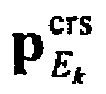
- the projection p E k crs of E k' in space ⁇ k and the projection p E k ' crs of E k in space ⁇ k' may be estimated, so that projection information may be increased, and ill-condition of the equation may be weakened.
- R is projection transformation on a continuous domain, which corresponds to the projection matrix H of a discrete domain.
- ⁇ E k , E k ' and ⁇ E k ', E k may be obtained using a machine learning method, for example, using an artificial neural network method.
- the projection data passing through an identical ray path collected from the projection at E k and E k' may be used as training data to obtain mapping relations ⁇ E k , E k ' and ⁇ E k ', E k .
- FIG. 2 illustrates a schematic diagram of image mapping.
- FIG. 3 illustrates a schematic diagram of learning taking a two-layer artificial neural network, where each layer has ten nodes (neurons), as an example.
- the original data are almost doubled, and the projection data in Formula (8) are employed for the final reconstruction. In this way, a dual-energy CT image having a higher quality may be obtained.
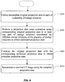
- FIG. 4 illustrates a flowchart of a spectral CT image reconstructing method based on the above conception according to an embodiment of the present disclosure.
- incomplete original projection data in each of a plurality of energy windows are collected.
- the incomplete original projection data may be collected by means of limited angle sampling, angle sparse sampling, or sparse detector sampling.
- a projection data cross estimation is performed using corresponding original projection data in at least one pair of energy windows constituted by different energy windows of the plurality of energy windows to obtain estimated projection data.
- Each pair of energy windows includes a first energy window and a second energy window.
- a mapping relation between image data in the first energy window and image data in the second energy window may be established on an image domain.
- the mapping relation may be established by means of a machine learning method. For example, first training image data are obtained by reconstructing using the first identical projection data, and second training image data are obtained by reconstructing using the second identical projection data. Next, a first mapping relation ⁇ E k , E k ' from the image data in the first energy window to the image data in the second energy window and/or a second mapping relation ⁇ E k ', E k from the image data in the second energy window to the image data in the first energy window are established by means of a machine learning method using the first training image data and the second training image data.
- the machine learning method may be, for example, an artificial neural network method, but the present disclosure is not limited thereto.
- estimated image data may be obtained using the mapping relation.
- first initial image data and/or second initial image data are respectively obtained by reconstructing in advance using the corresponding original projection data in the first energy window and the second energy window.
- second estimated image data in the second energy window are obtained by mapping the first initial image data by means of the first mapping relation
- first estimated image data in the first energy window are obtained by mapping the second initial image data by means of the second mapping relation.
- the estimated projection data are obtained from the estimated image data.
- first estimated projection data are obtained using the first estimated image data and a projection operator used in the first energy window
- second estimated projection data are obtained using the second estimated image data and a projection operator used in the second energy window.
- the original projection data are combined with the corresponding estimated projection data to obtain complete projection data.
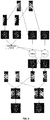
- FIG. 5 illustrates an example procedure of performing cross estimation and image reconstruction according to an embodiment of the present disclosure.
- FIG. 6 is a dental model used in the example procedure of FIG. 5 .
- FIG. 7 is a CT spectrum used in the example procedure of FIG. 5 .
- FIG. 8 is complete projection data of the dental model of FIG. 6 .
- the model as shown in FIG. 6 and the dual-energy CT spectrum in FIG. 7 are employed, and the two dual-energy energies herein correspond to the pair of E k and E k' in the foregoing method to perform data cross estimation so as to respectively perform limited angle sampling, angle sparse sampling or sparse detector sampling.
- FIG. 9 illustrates a schematic diagram of limited angle sampling dual-energy CT scanning, wherein a left side is a scanning trace, and a right side is a schematic diagram of projection down-sampling.
- 512 detectors are employed for limited angle CT scanning, one sampling every other degree from 1 degree to 90 degrees at high energy, and one sampling every other degree from 120 degrees to 210 degrees at low energy.
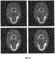
- the reconstruction results are as shown in FIG. 12 , wherein the left figure shows the result obtained according to the method of the present disclosure, and the right figure shows the result obtained by TV minimization constraint.
- FIG. 10 illustrates a schematic diagram of angle sparse sampling CT scanning, wherein a left side is a scanning trace, and a right side is a schematic diagram of projection down-sampling.
- the reconstruction results are as shown in FIG. 13 , wherein the left figure shows the result obtained according to the method of the present disclosure, and the right figure shows the result obtained by TV minimization constraint.
- FIG. 11 illustrates a schematic diagram of detector sparse sampling CT scanning, wherein a left side is a scanning trace, and a right side is a schematic diagram of projection down-sampling. There are 64 high energy detectors and 64 low energy detectors in a staggered arrangement. 360 projection angles are collected in a circle.
- a data size required for reconstruction may be significantly reduced using the method according to the embodiment of the present disclosure, which is applicable to angle sparse sampling, sparse detector sampling and the like, so that the number of the detectors and a radiation dose may be decreased to reduce the manufacturing cost of a CT system.
- the method of the present disclosure also may be used for reducing an angle coverage to reduce a z axis layer thickness and improve the time resolution.
- the method according to the embodiment of the present disclosure may effectively inhibit artifacts possibly caused by reduction of data.
- FIG. 14 schematically illustrates a schematic diagram of a system structure of a spectral CT imaging system 1400 according to some exemplary embodiments of the present disclosure.
- the spectral CT imaging system 1400 may include a ray generating device 1405, a mechanical movement system 1410, a photon-counting detector or energy-sensitive detector 1420, or a data collecting system 1430.
- the system according to the present disclosure may be implemented through circular orbit scanning, or also may be implemented through spiral trajectory scanning, and may be used for three-dimensional spectral CT imaging.
- the photon-counting detector or energy-sensitive detector 1420 may include a plurality of pixels and is configured to receive and process photons passing through an object.
- the photon-counting detector or energy-sensitive detector 1420 may be, for example, an area-array detector or annular detector. According to some embodiments of the present disclosure, the photon-counting detector or energy-sensitive detector 1420 includes an electronics system 1425.
- the ray generating device 1405 may include a ray source and is configured to emit, for example, X-ray.
- the mechanical movement system 1410 is configured to cause a relative movement between an imaged object and the ray source.
- the mechanical movement system 1410 may include, for example, a mechanical movement device and a corresponding control system (not shown).
- the imaged object 1415 may move while the ray source and/or the detector 1420 keeps still (as shown in FIG. 1 ), or the ray source and/or the detector may move while the object keeps still.
- turning patients around is avoided in the medical field, which may be implemented by rotating a source and/or a detector.
- manners of rotating and translating objects are relatively common. For CT imaging, what works is relative movement, and thus the two manners are equivalent.
- the data collecting system 1430 is configured to perform data collection on a photon passing through the imaged object 1415 from the photon-counting detector or energy-sensitive detector 1420.
- the spectral CT imaging system 1400 may further include a master controller 1440 and an image reconstruction system 1435.
- the master controller 1440 is in charge of master control of the running process of the spectral CT system, including mechanical rotation, electrical control, safety interlock control, and so on.
- the image reconstruction system 1435 is configured to process data obtained by the data collecting system 1430 to obtain an attenuation coefficient image of the spectral CT in an energy window.
- the master controller 1440 and the image reconstruction system 1435 may be single PCs or may be workstations or computer clusters.
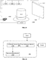
- FIG. 15 schematically illustrates modules of the image reconstruction system according to some exemplary embodiments of the present disclosure.
- the image reconstruction system includes a cross estimation module 1502, a combining module 1504, and a reconstructing module 1506.
- the cross estimation module 1502 is configured to perform a projection data cross estimation using corresponding original projection data in at least one pair of energy windows constituted by different energy windows of the plurality of energy windows to obtain estimated projection data.
- Each pair of energy windows includes a first energy window and a second energy window.
- the combining module 1504 is configured to combine the original projection data with the corresponding estimated projection data to obtain complete projection data.
- the reconstructing module 1506 is configured to reconstruct the spectral CT image using the complete projection data.
- the cross estimation module 1502 is configured to: establish, on an image domain, a mapping relation between image data in the first energy window and image data in the second energy window; obtain estimated image data using the mapping relation; and obtain the estimated projection data from the estimated image data.
- the image reconstruction system as shown in FIG. 15 may be configured to achieve the foregoing reconstruction method according to the present disclosure, which is not described any more.
- the reconstruction method and system according the embodiments of the present disclosure may be applied to the field of non-destructive inspection, medical diagnosis, safety inspection and the like.
- the method according to the embodiment of the present disclosure may obtain more projection data by using, for example, an artificial neural network to learn a mapping relation among dual-energy absorption coefficients.
- the artificial neural network may adopt online learning, and the projection data passing through the identical ray path are extracted, during reconstruction, as the training data, and may be adapted to the mapping relation among various unknown and complex absorption coefficients at different energies.
- the method may be applicable to solving the problem of incomplete data reconstruction under the condition that the projection data at different energies have a subset of a part of the projection data passing through the identical ray path, for example, limited angle and sparse sampling and the like, and the method has a good effect.
- the method according to the embodiment of the present disclosure may greatly reduce the data size required for reconstruction, is applicable to angle sparse sampling, sparse detector sampling and the like, may reduce the number of the detectors and the radiation dose to reduce the manufacturing cost of the CT system, may be used for reducing the angle coverage to reduce the z axis layer thickness and improve the time resolution, and thus has strong practicability and a wide scope of application.
- the method according to the embodiment of the present disclosure may effectively inhibit artifacts possibly caused by reduction of data.
- the reconstruction effect obtained by using this method may be equivalent to the effect of independent reconstruction of each energy of the dual-energy CT covering an angle of 150 degrees respectively.
- the embodiments of the present disclosure may be implemented by hardware or by means of software in combination with the necessary hardware.
- the technical solution according to the embodiments of the present disclosure may be embodied in the form of a software product which may be stored on a nonvolatile storage medium (which may be CD-ROM, flash memory, mobile hard disk and the like), including a number of instructions for enabling a computing device (which may be a personal computer, a server, a mobile terminal, or a network device and the like) to perform the method according to the embodiments of the present disclosure.
- a nonvolatile storage medium which may be CD-ROM, flash memory, mobile hard disk and the like
- a computing device which may be a personal computer, a server, a mobile terminal, or a network device and the like
- modules may be distributed in the apparatus as described in the embodiments, or may be modified in one or more devices different from the present embodiment.
- the modules of the above-described embodiments may be combined into one module or may be further divided into a plurality of submodules.
Landscapes
- Engineering & Computer Science (AREA)
- Physics & Mathematics (AREA)
- General Physics & Mathematics (AREA)
- Theoretical Computer Science (AREA)
- Health & Medical Sciences (AREA)
- General Health & Medical Sciences (AREA)
- Medical Informatics (AREA)
- Nuclear Medicine, Radiotherapy & Molecular Imaging (AREA)
- Radiology & Medical Imaging (AREA)
- Quality & Reliability (AREA)
- Computer Vision & Pattern Recognition (AREA)
- Apparatus For Radiation Diagnosis (AREA)
Abstract
Description
- This application is based on and claims priority to Chinese Patent Application No.
201510572013.0, filed September 9, 2015 - The present disclosure relates to the field of spectral CT imaging technologies, and more particularly, to a spectral CT image reconstructing method and a spectral CT imaging system based on machine learning and projection domain estimation.
- Dual-energy CT was put forward in the 1970s. With the development of X-ray detectors and imaging systems, dual-energy CT is widely used. In recent years, with the development of technologies related to detectors and further demands for CT imaging, spectral CT using dual-energy or multi-energy (i.e., X-ray with two and more energy spectrums is employed to pass through objects to form signals for imaging, which is generally referred to as X-ray of a plurality of energy windows or energy channels) attracts widespread attention and flourishes in practical application. Compared with traditional mono-energy CT, the spectral CT not only gets rid of defects of spectrum hardening and insufficient contrast, but also can distinguish materials, especially materials with the same absorption coefficient at certain energies. These advantages make the spectral CT available for numerous clinical applications such as abdominal imaging and lung disease detection, etc.
- In general, the spectral CT at each energy needs to collect complete CT data. Taking the fan-beam CT as an example, a complete projection dataset should cover a short-scan angle (180 degrees plus a fan-beam angle). The traditional multi-energy data collection requires a short scan at different energies for many times; or a dual-source or multi-source CT are employed to perform a single scan; or an energy resolution detector such as a photon-counting detector is employed to perform a single scan to acquire multi-energy projection data. The above solutions may encounter problems such as increased radiation dose, long scanning time and high hardware cost, etc.
- One solution is to avoid collecting complete CT data. However, this solution is faced with a problem of inadequate projection data for reconstruction. For this reason, according to a general solution, compression sensing technologies are employed. That is, supposing the signal is sparse or becomes sparse in a transform domain, namely

- wherein x ∈ R n denotes an original signal, Ψ(·) denotes a sparse operator, and s denotes sparseness. In practical application, generally L0 norm is replaced with L1 norm, which changes the problem into a convex programming problem, wherein A denotes a forward projection, and b denotes measured projection data:

- However, an improved spectral CT image reconstruction algorithm is still required.
- The above-mentioned information disclosed in this Background section is only for the purpose of enhancing the understanding of background of the present disclosure and may therefore include information that does not constitute a prior art that is known to those of ordinary skill in the art.
- This application discloses a spectral CT image reconstructing method based on machine learning and projection domain estimation, which can solve the foregoing reconstruction problem.
- Other features and advantages of the present disclosure will become apparent from the following detailed description, or in part, by practice of the present disclosure.
- According to an aspect of the present disclosure, there is provided a spectral CT image reconstructing method, including: collecting incomplete original projection data in each of a plurality of energy windows; performing a projection data cross estimation using corresponding original projection data in at least one pair of energy windows constituted by different energy windows of the plurality of energy windows to obtain estimated projection data, wherein each pair of energy windows includes a first energy window and a second energy window; combining the original projection data with the corresponding estimated projection data to obtain complete projection data; and reconstructing a spectral CT image using the complete projection data.
- According to some embodiments, performing a projection data cross estimation using corresponding original projection data in at least one pair of energy windows constituted by different energy windows of the plurality of energy windows to obtain estimated projection data includes: establishing, on an image domain, a mapping relation between image data in the first energy window and image data in the second energy window; obtaining estimated image data using the mapping relation; and obtaining the estimated projection data from the estimated image data.
- According to some embodiments, establishing, on an image domain, a mapping relation between image data in the first energy window and image data in the second energy window includes: extracting, from the corresponding original projection data of the first energy window and of the second energy window, first identical projection data in the first energy window and second identical projection data in the second energy window passing through an identical ray path; reconstructing using the first identical projection data to obtain first training image data; reconstructing using the second identical projection data to obtain second training image data; and establishing, by means of a machine learning method using the first training image data and the second training image data, a first mapping relation from the image data in the first energy window to the image data in the second energy window and/or a second mapping relation from the image data in the second energy window to the image data in the first energy window.
- According to some embodiments, obtaining estimated image data using the mapping relation includes: respectively obtaining first initial image data and/or second initial image data by reconstructing in advance using the corresponding original projection data in the first energy window and the second energy window; and obtaining second estimated image data in the second energy window by mapping the first initial image data by means of the first mapping relation, and/or obtaining first estimated image data in the first energy window by mapping the second initial image data by means of the second mapping relation.
- According to some embodiments, obtaining the estimated projection data from the estimated image data includes: obtaining first estimated projection data using the first estimated image data and a projection operator used in the first energy window, and/or obtaining second estimated projection data using the second estimated image data and a projection operator used in the second energy window.
- According to some embodiments, collecting incomplete original projection data in each of a plurality of energy windows includes limited angle sampling, angle sparse sampling, or sparse detector sampling.
- According to another aspect of the present disclosure, there is provided a spectral CT imaging system, including: a ray generating device, including a ray source; a photon-counting detector or an energy-sensitive detector, including a plurality of pixels; a data collecting system, configured to perform data collection on a photon passing through an imaged object from the photon-counting detector or energy-sensitive detector; and an image reconstruction system, configured to reconstruct a spectral CT image using data acquired by the data collecting system. The data collecting system is configured to collect incomplete original projection data in each of a plurality of energy windows. The image reconstruction system includes: a cross estimation module, configured to perform a projection data cross estimation using corresponding original projection data in at least one pair of energy windows constituted by different energy windows of the plurality of energy windows to obtain estimated projection data, wherein each pair of energy windows includes a first energy window and a second energy window; a combining module, configured to combine the original projection data with the corresponding estimated projection data to obtain complete projection data; and a reconstructing module, configured to reconstruct the spectral CT image using the complete projection data.
- According to some embodiments, the cross estimation module is configured to: establish, on an image domain, a mapping relation between image data in the first energy window and image data in the second energy window; obtain estimated image data using the mapping relation; and obtain the estimated projection data from the estimated image data.
- According to some embodiments, establishing, on an image domain, a mapping relation between image data in the first energy window and image data in the second energy window includes: extracting, from the corresponding original projection data of the first energy window and of the second energy window, first identical projection data in the first energy window and second identical projection data in the second energy window passing through an identical ray path; reconstructing using the first identical projection data to obtain first training image data; reconstructing using the second identical projection data to obtain second training image data; and establishing, by means of a machine learning method using the first training image data and the second training image data, a first mapping relation from the image data in the first energy window to the image data in the second energy window and/or a second mapping relation from the image data in the second energy window to the image data in the first energy window.
- According to some embodiments, obtaining estimated image data using the mapping relation includes: respectively obtaining first initial image data and/or second initial image data by reconstructing in advance using the corresponding original projection data in the first energy window and the second energy window; and obtaining second estimated image data in the second energy window by mapping the first initial image data by means of the first mapping relation, and/or obtaining first estimated image data in the first energy window by mapping the second initial image data by means of the second mapping relation.
- According to some embodiments, obtaining the estimated projection data from the estimated image data includes: obtaining first estimated projection data using the first estimated image data and a projection operator used in the first energy window, and/or obtaining second estimated projection data using the second estimated image data and a projection operator used in the second energy window.
- Using the spectral CT image reconstructing method according to some embodiments of the present disclosure, a relation between spectral CT absorption coefficients is learned using, for example, an artificial neural network, and then projection data not collected are estimated. In this way, the problem of inadequate projection data for reconstruction can be solved.
- The above and other features and advantages of the present disclosure will become more apparent by describing in detail the exemplary embodiments thereof with reference to the accompanying drawings.
-
FIG. 1 illustrates cross estimation of data space in paired energy windows in an exemplary system of three energy windows; -
FIG. 2 illustrates a schematic diagram of image mapping; -
FIG. 3 illustrates a schematic diagram of learning taking a two-layer artificial neural network, where each layer has ten nodes (neurons), as an example; -
FIG. 4 illustrates a flowchart of a spectral CT image reconstructing method based on the above conception according to an embodiment of the present disclosure; -
FIG. 5 illustrates an example procedure of performing cross estimation and image reconstruction according to an embodiment of the present disclosure; -
FIG. 6 is a dental model used in the example procedure ofFIG. 5 ; -
FIG. 7 is a CT spectrum used in the example procedure ofFIG. 5 ; -
FIG. 8 is complete projection data of the dental model ofFIG. 6 ; -
FIG. 9 illustrates a schematic diagram of limited angle sampling dual-energy CT scanning according to an embodiment of the present disclosure, wherein a left side is a scanning trace, and a right side is a schematic diagram of projection down-sampling; -
FIG. 10 illustrates a schematic diagram of angle sparse sampling CT scanning according to an embodiment of the present disclosure, wherein a left side is a scanning trace, and a right side is a schematic diagram of projection down-sampling; -
FIG. 11 illustrates a schematic diagram of detector sparse sampling CT scanning according to an embodiment of the present disclosure, wherein a left side is a scanning trace, and a right side is a schematic diagram of projection down-sampling; -
FIG. 12 illustrates a simulation result of performing image reconstruction on sampled data ofFIG. 9 using the method of the present disclosure; -
FIG. 13 illustrates a simulation result of performing image reconstruction on sampled data ofFIG. 10 using the method of the present disclosure; -
FIG. 14 schematically illustrates a schematic diagram of a system structure of a spectral CT imaging system according to some exemplary embodiments of the present disclosure; and -
FIG. 15 schematically illustrates modules constituting an image reconstruction system according to some exemplary embodiments of the present disclosure. - The exemplary embodiment will now be described more fully with reference to the accompanying drawings. However, the exemplary embodiments can be implemented in a variety of forms and should not be construed as limited to the embodiments set forth herein. Rather, the embodiments are provided so that this disclosure will be thorough and complete and will fully convey the concepts of exemplary embodiments to those skilled in the art. The same reference numerals in the drawings denote the same or similar parts, and thus repeated description thereof will be omitted.
- In addition, the features, structures, or characteristics described may be combined in one or more embodiments in any suitable manner. In the following description, numerous specific details are provided to give a full understanding of the embodiments of the present disclosure. However, those skilled in the art will appreciate that one or more of the specific details may be practiced without practicing the technical solutions of the present disclosure, and other methods, components, materials, devices, steps, and the like may be employed. In other instances, well-known structures, methods, devices, implementations, materials, or operations are not shown or described in detail to avoid obscuring aspects of the present disclosure.
- The block diagrams illustrated in the drawings are merely functional entities and do not necessarily correspond to any physically separate entity. In other words, these functional entities may be implemented in software form, or implemented in one or more hardware modules or integrated circuits, or implemented in different networks and/or processor devices and/or microcontroller devices.
- The flowcharts as shown in the accompanying drawings are merely exemplary description instead of necessarily including all the steps. For example, some steps may be broken down, while some steps may be combined or partly combined. Therefore, the actual execution sequences may be changed according to the actual conditions.
- According to the inventive concepts of the prevent disclosure, projection data cross estimation is performed using pairwise data in different energy windows.
-
FIG. 1 illustrates cross estimation of data space in paired energy windows in an exemplary system of three energy windows. - Referring to the system of the three energy windows as shown in
FIG. 1 , the outermostsolid line boxes solid line boxes - Only a part of data are collected in each energy window: energies E1 and E2 are used as a pair, and cross estimation is performed on a part of missing data in energy E1 and a part of missing data in energy E2 ; energies E1 and E3 are used as a pair, and cross estimation is performed on a part of missing data in energy E1 and a part of missing data in energy E3 ; and also energies E2 and E3 may be used as a pair, and cross estimation is performed on a part of missing data in energy E2 and a part of missing data in energy E3 .
- A method of projection data cross estimation is illustrated below by taking any pair of energies Ek and Ek' as an example.
- In this method, projection data collected at Ek and E k' whose projections pass through an identical ray path are extracted to determine a mapping relation. Herein, a projection consistent with a ray direction may be used, or projections of conjugate rays may be used.
- Supposing equivalent linear attenuation coefficient images at a pair of energies are f E
k = {f Ek ,1,f Ek ,2,L,fEk ,N } and f Ek ' = {f Ek ',1,f Ek ',2,L,f Ek ',N }, projection data obtained through CT scanning at each energy respectively are p Ek = {P Ek ,1,P Ek ,2 ,L,PEk ,Mk }, with corresponding data space being denoted by Ω k , and p Ek = {p Ek ,1 ,p Ek ,2,L,pEk ',Mk ' }, with corresponding data space being denoted by Ω k'. Line integral projection operators are denoted by - H E
k = {hEk ,ij } Mk ×N and H Ek ' = {hEk ,ij } Mk '×N . The problem for directly performing iterative reconstruction is as follows:
- wherein E corresponds to E ∈ {Ek,Ek' }, N represents the number of pixels of a reconstructed image, Mk and M k' represent the number rays, ij represent elements of a matrix corresponding to an i-th ray and a j-th pixel respectively. The equation is ill-conditioned because Mk ,Mk' < N in the projection matrix. In the present disclosure, by establishing a mapping from the projection data at Ek to the projection data at Ek' or a mapping from the projection data at Ek' to the projection data at Ek,

- the projection


k ,Ek ' : f Ek → f Ek ' (ΨEk ',Ek : f Ek ' → f Ek ), so that the projection domain mapping may be expressed as:
- wherein the R is projection transformation on a continuous domain, which corresponds to the projection matrix H of a discrete domain. Ψ Ek ,Ek ' and Ψ Ek ',Ek may be obtained using a machine learning method, for example, using an artificial neural network method. The projection data passing through an identical ray path collected from the projection at Ek and Ek' may be used as training data to obtain mapping relations Ψ Ek ,Ek ' and Ψ Ek ', E
k . - For example, at first, images




- wherein n is a pixel subscript n = 1,2,...,N, and N is a d×d neighbor domain taking the n as a center. f(N) is taken as an input of the artificial neural network, and f(n) is taken as an output.
FIG. 2 illustrates a schematic diagram of image mapping.FIG. 3 illustrates a schematic diagram of learning taking a two-layer artificial neural network, where each layer has ten nodes (neurons), as an example. - Mapping relations Ψ Ek ,Ek ' and Ψ Ek ',Ek are known, it is estimated:

- Complete projection data may be obtained by combining the estimated projection data with the original projection data:

- The original data are almost doubled, and the projection data in Formula (8) are employed for the final reconstruction. In this way, a dual-energy CT image having a higher quality may be obtained.
-
FIG. 4 illustrates a flowchart of a spectral CT image reconstructing method based on the above conception according to an embodiment of the present disclosure. - As shown in
FIG. 4 , in S410, incomplete original projection data in each of a plurality of energy windows are collected. For example, the incomplete original projection data may be collected by means of limited angle sampling, angle sparse sampling, or sparse detector sampling. - In S420, a projection data cross estimation is performed using corresponding original projection data in at least one pair of energy windows constituted by different energy windows of the plurality of energy windows to obtain estimated projection data. Each pair of energy windows includes a first energy window and a second energy window.
- For example, a mapping relation between image data in the first energy window and image data in the second energy window may be established on an image domain.
- The mapping relation may be established by means of a machine learning method. For example, first training image data are obtained by reconstructing using the first identical projection data, and second training image data are obtained by reconstructing using the second identical projection data. Next, a first mapping relation Ψ Ek ,Ek ' from the image data in the first energy window to the image data in the second energy window and/or a second mapping relation Ψ Ek ',Ek from the image data in the second energy window to the image data in the first energy window are established by means of a machine learning method using the first training image data and the second training image data. The machine learning method may be, for example, an artificial neural network method, but the present disclosure is not limited thereto.
- Next, estimated image data may be obtained using the mapping relation. For example, first initial image data and/or second initial image data are respectively obtained by reconstructing in advance using the corresponding original projection data in the first energy window and the second energy window. Next, second estimated image data in the second energy window are obtained by mapping the first initial image data by means of the first mapping relation, and first estimated image data in the first energy window are obtained by mapping the second initial image data by means of the second mapping relation.
- Next, the estimated projection data are obtained from the estimated image data. For example, first estimated projection data are obtained using the first estimated image data and a projection operator used in the first energy window, and second estimated projection data are obtained using the second estimated image data and a projection operator used in the second energy window.
- In S430, the original projection data are combined with the corresponding estimated projection data to obtain complete projection data.
- In S440, a spectral CT image is reconstructed using the complete projection data.
-
FIG. 5 illustrates an example procedure of performing cross estimation and image reconstruction according to an embodiment of the present disclosure.FIG. 6 is a dental model used in the example procedure ofFIG. 5 .FIG. 7 is a CT spectrum used in the example procedure ofFIG. 5 .FIG. 8 is complete projection data of the dental model ofFIG. 6 . - (1) Projection data p E
k and p Ek' passing through an identical ray path are extracted from the original projection data


- (2) The training image data


k → f Ek' , Ψ Ek' ,Ek : f Ek' → f Ek . - (3) Reconstruction is performed in advance using the projection data p E
k and p Ek' , and the initial image data

- (4) Cross estimation, estimated image data are obtained using the mapping relation:

- (5) Projection, the estimated projection data are obtained from the estimated image data:

- (6) The original projection data are combined with the estimated projection data:

- (7) Final reconstruction, complete data


- According to the embodiment, the model as shown in
FIG. 6 and the dual-energy CT spectrum inFIG. 7 are employed, and the two dual-energy energies herein correspond to the pair of Ek and Ek' in the foregoing method to perform data cross estimation so as to respectively perform limited angle sampling, angle sparse sampling or sparse detector sampling. -
FIG. 9 illustrates a schematic diagram of limited angle sampling dual-energy CT scanning, wherein a left side is a scanning trace, and a right side is a schematic diagram of projection down-sampling. 512 detectors are employed for limited angle CT scanning, one sampling every other degree from 1 degree to 90 degrees at high energy, and one sampling every other degree from 120 degrees to 210 degrees at low energy. The reconstruction results are as shown inFIG. 12 , wherein the left figure shows the result obtained according to the method of the present disclosure, and the right figure shows the result obtained by TV minimization constraint. -
FIG. 10 illustrates a schematic diagram of angle sparse sampling CT scanning, wherein a left side is a scanning trace, and a right side is a schematic diagram of projection down-sampling. 512 detectors are employed for angle sparse sampling CT scanning, 36 angles V Ek = {10°,20°,...,360°} are collected in a circle at high energy, and 24 angles V Ek' = {15°, 30°,...,360°} are collected in a circle at low energy. The reconstruction results are as shown inFIG. 13 , wherein the left figure shows the result obtained according to the method of the present disclosure, and the right figure shows the result obtained by TV minimization constraint. -
FIG. 11 illustrates a schematic diagram of detector sparse sampling CT scanning, wherein a left side is a scanning trace, and a right side is a schematic diagram of projection down-sampling. There are 64 high energy detectors and 64 low energy detectors in a staggered arrangement. 360 projection angles are collected in a circle. - As can be seen from the above results, a data size required for reconstruction may be significantly reduced using the method according to the embodiment of the present disclosure, which is applicable to angle sparse sampling, sparse detector sampling and the like, so that the number of the detectors and a radiation dose may be decreased to reduce the manufacturing cost of a CT system. Furthermore, the method of the present disclosure also may be used for reducing an angle coverage to reduce a z axis layer thickness and improve the time resolution. In addition, the method according to the embodiment of the present disclosure may effectively inhibit artifacts possibly caused by reduction of data.
-
FIG. 14 schematically illustrates a schematic diagram of a system structure of a spectralCT imaging system 1400 according to some exemplary embodiments of the present disclosure. - As shown in
FIG. 14 , the spectralCT imaging system 1400 may include aray generating device 1405, amechanical movement system 1410, a photon-counting detector or energy-sensitive detector 1420, or adata collecting system 1430. The system according to the present disclosure may be implemented through circular orbit scanning, or also may be implemented through spiral trajectory scanning, and may be used for three-dimensional spectral CT imaging. - The photon-counting detector or energy-
sensitive detector 1420 may include a plurality of pixels and is configured to receive and process photons passing through an object. The photon-counting detector or energy-sensitive detector 1420 may be, for example, an area-array detector or annular detector. According to some embodiments of the present disclosure, the photon-counting detector or energy-sensitive detector 1420 includes anelectronics system 1425. - The
ray generating device 1405 may include a ray source and is configured to emit, for example, X-ray. - The
mechanical movement system 1410 is configured to cause a relative movement between an imaged object and the ray source. Themechanical movement system 1410 may include, for example, a mechanical movement device and a corresponding control system (not shown). The imagedobject 1415 may move while the ray source and/or thedetector 1420 keeps still (as shown inFIG. 1 ), or the ray source and/or the detector may move while the object keeps still. Generally, turning patients around is avoided in the medical field, which may be implemented by rotating a source and/or a detector. In the industrial non-destructive inspection, manners of rotating and translating objects are relatively common. For CT imaging, what works is relative movement, and thus the two manners are equivalent. - The
data collecting system 1430 is configured to perform data collection on a photon passing through the imagedobject 1415 from the photon-counting detector or energy-sensitive detector 1420. - The spectral
CT imaging system 1400 may further include amaster controller 1440 and animage reconstruction system 1435. Themaster controller 1440 is in charge of master control of the running process of the spectral CT system, including mechanical rotation, electrical control, safety interlock control, and so on. Theimage reconstruction system 1435 is configured to process data obtained by thedata collecting system 1430 to obtain an attenuation coefficient image of the spectral CT in an energy window. Themaster controller 1440 and theimage reconstruction system 1435 may be single PCs or may be workstations or computer clusters. -
FIG. 15 schematically illustrates modules of the image reconstruction system according to some exemplary embodiments of the present disclosure. - As shown in
FIG. 15 , the image reconstruction system includes across estimation module 1502, a combiningmodule 1504, and a reconstructingmodule 1506. - The
cross estimation module 1502 is configured to perform a projection data cross estimation using corresponding original projection data in at least one pair of energy windows constituted by different energy windows of the plurality of energy windows to obtain estimated projection data. Each pair of energy windows includes a first energy window and a second energy window. - The combining
module 1504 is configured to combine the original projection data with the corresponding estimated projection data to obtain complete projection data. - The reconstructing
module 1506 is configured to reconstruct the spectral CT image using the complete projection data. - According to some embodiments, the
cross estimation module 1502 is configured to: establish, on an image domain, a mapping relation between image data in the first energy window and image data in the second energy window; obtain estimated image data using the mapping relation; and obtain the estimated projection data from the estimated image data. - The image reconstruction system as shown in
FIG. 15 may be configured to achieve the foregoing reconstruction method according to the present disclosure, which is not described any more. - Through the above detailed description, those skilled in the art readily understand that the system and method according the embodiments of the present disclosure have one or more of the following advantages.
- The reconstruction method and system according the embodiments of the present disclosure may be applied to the field of non-destructive inspection, medical diagnosis, safety inspection and the like. Compared with the existing reconstruction algorithm based on compressed sensing and a prior image (generally data at a single energy are used, or multi-energy data must be employed to perform determinant order minimization), the method according to the embodiment of the present disclosure may obtain more projection data by using, for example, an artificial neural network to learn a mapping relation among dual-energy absorption coefficients. The artificial neural network may adopt online learning, and the projection data passing through the identical ray path are extracted, during reconstruction, as the training data, and may be adapted to the mapping relation among various unknown and complex absorption coefficients at different energies. The method may be applicable to solving the problem of incomplete data reconstruction under the condition that the projection data at different energies have a subset of a part of the projection data passing through the identical ray path, for example, limited angle and sparse sampling and the like, and the method has a good effect.
- The method according to the embodiment of the present disclosure may greatly reduce the data size required for reconstruction, is applicable to angle sparse sampling, sparse detector sampling and the like, may reduce the number of the detectors and the radiation dose to reduce the manufacturing cost of the CT system, may be used for reducing the angle coverage to reduce the z axis layer thickness and improve the time resolution, and thus has strong practicability and a wide scope of application.
- The method according to the embodiment of the present disclosure may effectively inhibit artifacts possibly caused by reduction of data. In terms of reducing the data projection of the spectral CT, if two energies only cover an angle of 90 degrees respectively, the reconstruction effect obtained by using this method may be equivalent to the effect of independent reconstruction of each energy of the dual-energy CT covering an angle of 150 degrees respectively.
- With description of the above embodiments, it will be readily understood by those skilled in the art that the embodiments of the present disclosure may be implemented by hardware or by means of software in combination with the necessary hardware. Thus, the technical solution according to the embodiments of the present disclosure may be embodied in the form of a software product which may be stored on a nonvolatile storage medium (which may be CD-ROM, flash memory, mobile hard disk and the like), including a number of instructions for enabling a computing device (which may be a personal computer, a server, a mobile terminal, or a network device and the like) to perform the method according to the embodiments of the present disclosure.
- It will be understood by those skilled in the art that the drawings are merely schematic diagrams of exemplary embodiments and that the modules or processes in the drawings are not indispensably necessary to implement the present disclosure and are therefore not intended to limit the scope of protection of the present disclosure.
- It will be understood by those skilled in the art that the above-described modules may be distributed in the apparatus as described in the embodiments, or may be modified in one or more devices different from the present embodiment. The modules of the above-described embodiments may be combined into one module or may be further divided into a plurality of submodules.
- Exemplary embodiments of the present disclosure are particularly shown and described as above. It is to be understood that the present disclosure is not limited to the disclosed embodiments, but rather that the present disclosure is intended to cover various modifications and equivalent arrangements included within the spirit and scope of the appended claims.
Claims (11)
- A spectral CT image reconstructing method, characterized in comprising:collecting incomplete original projection data in each of a plurality of energy windows;performing a projection data cross estimation using corresponding original projection data in at least one pair of energy windows constituted by different energy windows of the plurality of energy windows to obtain estimated projection data, wherein each pair of energy windows comprises a first energy window and a second energy window;combining the original projection data with the corresponding estimated projection data to obtain complete projection data; andreconstructing a spectral CT image using the complete projection data.
- The spectral CT image reconstructing method according to claim 1, wherein the performing a projection data cross estimation using corresponding original projection data in at least one pair of energy windows constituted by different energy windows of the plurality of energy windows to obtain estimated projection data comprises:establishing, on an image domain, a mapping relation between image data in the first energy window and image data in the second energy window;obtaining estimated image data using the mapping relation; andobtaining the estimated projection data from the estimated image data.
- The spectral CT image reconstructing method according to claim 2, wherein the establishing, on an image domain, a mapping relation between image data in the first energy window and image data in the second energy window comprises:extracting, from the corresponding original projection data of the first energy window and of the second energy window, first identical projection data in the first energy window and second identical projection data in the second energy window passing through an identical ray path;reconstructing using the first identical projection data to obtain first training image data;reconstructing using the second identical projection data to obtain second training image data; andestablishing, by means of a machine learning method using the first training image data and the second training image data, a first mapping relation from the image data in the first energy window to the image data in the second energy window and/or a second mapping relation from the image data in the second energy window to the image data in the first energy window.
- The spectral CT image reconstructing method according to claim 3, wherein obtaining estimated image data using the mapping relation comprises:respectively obtaining first initial image data and/or second initial image data by reconstructing in advance using the corresponding original projection data in the first energy window and the second energy window; andobtaining second estimated image data in the second energy window by mapping the first initial image data by means of the first mapping relation, and/or obtaining first estimated image data in the first energy window by mapping the second initial image data by means of the second mapping relation.
- The spectral CT image reconstructing method according to claim 4, wherein the obtaining the estimated projection data from the estimated image data comprises:
obtaining first estimated projection data using the first estimated image data and a projection operator used in the first energy window, and/or obtaining second estimated projection data using the second estimated image data and a projection operator used in the second energy window. - The spectral CT image reconstructing method according to claim 1, wherein the collecting incomplete original projection data in each of a plurality of energy windows comprises limited angle sampling, angle sparse sampling, or sparse detector sampling.
- A spectral CT imaging system, comprising:a ray generating device, comprising a ray source;a photon-counting detector or an energy-sensitive detector, comprising a plurality of pixels;a data collecting system, configured to perform data collection on a photon passing through an imaged object from the photon-counting detector or energy-sensitive detector; andan image reconstruction system, configured to reconstruct a spectral CT image using data acquired by the data collecting system,characterized in that,the data collecting system is configured to collect incomplete original projection data in each of a plurality of energy windows; andthe image reconstruction system comprises:a cross estimation module configured to perform a projection data cross estimation using corresponding original projection data in at least one pair of energy windows constituted by different energy windows of the plurality of energy windows to obtain estimated projection data, wherein each pair of energy windows comprises a first energy window and a second energy window;a combining module configured to combine the original projection data with the corresponding estimated projection data to obtain complete projection data; anda reconstructing module configured to reconstruct the spectral CT image using the complete projection data.
- The spectral CT imaging system according to claim 7, wherein the cross estimation module is configured to:establish, on an image domain, a mapping relation between image data in the first energy window and image data in the second energy window;obtain estimated image data using the mapping relation; andobtain the estimated projection data from the estimated image data.
- The spectral CT imaging system according to claim 8, wherein the establish, on an image domain, a mapping relation between image data in the first energy window and image data in the second energy window comprises:extracting, from the corresponding original projection data of the first energy window and of the second energy window, first identical projection data in the first energy window and second identical projection data in the second energy window passing through an identical ray path;reconstructing using the first identical projection data to obtain first training image data;reconstructing using the second identical projection data to obtain second training image data; andestablishing, by means of a machine learning method using the first training image data and the second training image data, a first mapping relation from the image data in the first energy window to the image data in the second energy window and/or a second mapping relation from the image data in the second energy window to the image data in the first energy window.
- The spectral CT imaging system according to claim 9, wherein the obtaining estimated image data using the mapping relation comprises:respectively obtaining first initial image data and/or second initial image data by reconstructing in advance using the corresponding original projection data in the first energy window and the second energy window; andobtaining second estimated image data in the second energy window by mapping the first initial image data by means of the first mapping relation, and/or obtaining first estimated image data in the first energy window by mapping the second initial image data by means of the second mapping relation.
- The spectral CT imaging system according to claim 10, wherein the obtaining the estimated projection data from the estimated image data comprises:
obtaining first estimated projection data using the first estimated image data and a projection operator used in the first energy window, and/or obtaining second estimated projection data using the second estimated image data and a projection operator used in the second energy window.
Applications Claiming Priority (2)
| Application Number | Priority Date | Filing Date | Title |
|---|---|---|---|
| CN201510572013.0A CN106530366B (en) | 2015-09-09 | 2015-09-09 | Energy spectral CT image reconstruction method and energy spectral CT imaging system |
| PCT/CN2016/096191 WO2017041620A1 (en) | 2015-09-09 | 2016-08-22 | Spectral ct image reconstructing method and spectral ct imaging system |
Publications (3)
| Publication Number | Publication Date |
|---|---|
| EP3321886A1 true EP3321886A1 (en) | 2018-05-16 |
| EP3321886A4 EP3321886A4 (en) | 2019-04-03 |
| EP3321886B1 EP3321886B1 (en) | 2021-11-17 |
Family
ID=58240582
Family Applications (1)
| Application Number | Title | Priority Date | Filing Date |
|---|---|---|---|
| EP16843558.4A Not-in-force EP3321886B1 (en) | 2015-09-09 | 2016-08-22 | Spectral ct image reconstructing method and spectral ct imaging system |
Country Status (4)
| Country | Link |
|---|---|
| US (1) | US10489939B2 (en) |
| EP (1) | EP3321886B1 (en) |
| CN (1) | CN106530366B (en) |
| WO (1) | WO2017041620A1 (en) |
Families Citing this family (14)
| Publication number | Priority date | Publication date | Assignee | Title |
|---|---|---|---|---|
| US11017269B2 (en) * | 2016-09-30 | 2021-05-25 | General Electric Company | System and method for optimization of deep learning architecture |
| JP7123983B2 (en) * | 2017-06-16 | 2022-08-23 | レンセラー ポリテクニック インスティテュート | Systems and methods for integrating tomographic image reconstruction and radiomics using neural networks |
| CN109242920B (en) * | 2017-07-11 | 2020-06-02 | 清华大学 | Substance decomposition method, device and system |
| WO2019019199A1 (en) | 2017-07-28 | 2019-01-31 | Shenzhen United Imaging Healthcare Co., Ltd. | System and method for image conversion |
| CN108010096A (en) * | 2017-11-30 | 2018-05-08 | 上海联影医疗科技有限公司 | CBCT image rebuilding methods, device and CBCT equipment |
| WO2019128660A1 (en) * | 2017-12-29 | 2019-07-04 | 清华大学 | Method and device for training neural network, image processing method and device and storage medium |
| KR102094598B1 (en) * | 2018-05-29 | 2020-03-27 | 한국과학기술원 | Method for processing sparse-view computed tomography image using artificial neural network and apparatus therefor |
| CN110084864B (en) * | 2019-04-09 | 2023-04-28 | 南京航空航天大学 | An Electron Density Image Reconstruction Method Based on Spectral CT |
| CN111179228A (en) * | 2019-12-16 | 2020-05-19 | 浙江大学 | A single-energy CT spectral imaging method based on deep learning |
| CN111067561B (en) * | 2019-12-25 | 2023-05-02 | 东软医疗系统股份有限公司 | Energy spectrum CT substance decomposition method and device, CT equipment and CT system |
| EP4057229A1 (en) * | 2021-03-12 | 2022-09-14 | Fraunhofer-Gesellschaft zur Förderung der angewandten Forschung e.V. | Processing device for obtaining gap filler sinogram information, computer tomograph, method and computer program |
| EP4080459A1 (en) * | 2021-04-23 | 2022-10-26 | Koninklijke Philips N.V. | Machine learning-based improvement in iterative image reconstruction |
| US11844639B2 (en) | 2021-10-29 | 2023-12-19 | GE Precision Healthcare LLC | System and method for utilizing dual energy imaging in a computed tomography imaging system |
| US20240265591A1 (en) * | 2023-02-03 | 2024-08-08 | GE Precision Healthcare LLC | Systems and methods for interpolation of dual-energy ct data |
Family Cites Families (19)
| Publication number | Priority date | Publication date | Assignee | Title |
|---|---|---|---|---|
| CN1300938A (en) * | 1999-12-22 | 2001-06-27 | 上海交通大学 | Imaging method for X-CT finite-angle projection data |
| US6907102B1 (en) * | 2002-12-16 | 2005-06-14 | Ken Sauer | Iterative reconstruction methods for multi-slice computed tomography |
| EP1759225B1 (en) * | 2004-06-09 | 2010-12-01 | Philips Intellectual Property & Standards GmbH | Computerized tomography method with helical relative movement and conical beam |
| EP1622085A1 (en) * | 2004-07-19 | 2006-02-01 | Deutsches Krebsforschungszentrum | Method of producing x-ray computer tomography images from limited data of an image object |
| DE102005027963B3 (en) * | 2005-06-16 | 2006-12-07 | Siemens Ag | Method of reconstructing three dimensional image data set of moved object from set of projected images taken from different directions involves dividing images into several partial sets taken during given phases of object movement |
| CN100570343C (en) * | 2006-06-13 | 2009-12-16 | 北京航空航天大学 | Wide view-field three-D CT imaging method |
| US8175361B2 (en) * | 2007-02-23 | 2012-05-08 | Siemens Aktiengesellschaft | Method and apparatus for the artifact-reduced detection of a 3D object in tomographic imaging |
| US7813474B2 (en) * | 2007-10-09 | 2010-10-12 | General Electric Company | Method and apparatus for performing dual-spectrum CT with fast KV modulation at multiple-view intervals |
| US8165264B2 (en) * | 2009-01-28 | 2012-04-24 | Kabushiki Kaisha Toshiba | Method of pre-reconstruction decomposition for fast kV-switching acquisition in dual energy computed tomography (CT) |
| US8050479B2 (en) * | 2009-02-26 | 2011-11-01 | General Electric Company | Method and system for generating a computed tomography image |
| CN102362292A (en) * | 2009-03-26 | 2012-02-22 | 皇家飞利浦电子股份有限公司 | Method and apparatus for computed tomography image reconstruction |
| WO2010127241A2 (en) * | 2009-04-30 | 2010-11-04 | The Regents Of The University Of California | System and methods for fast implementation of equally-sloped tomography |
| CN102947864B (en) * | 2010-06-21 | 2015-08-12 | 皇家飞利浦电子股份有限公司 | For performing the method and system of low-dose CT imaging |
| JP5997180B2 (en) * | 2011-02-01 | 2016-09-28 | コーニンクレッカ フィリップス エヌ ヴェKoninklijke Philips N.V. | Method and system for dual energy CT image reconstruction |
| CN103913472B (en) * | 2012-12-31 | 2016-04-20 | 同方威视技术股份有限公司 | Ct imaging system and method |
| CN104240270B (en) | 2013-06-14 | 2017-12-05 | 同方威视技术股份有限公司 | CT imaging methods and system |
| CN104323789B (en) * | 2014-09-25 | 2017-08-25 | 沈阳东软医疗系统有限公司 | A kind of CT scan image rebuilding method and CT scanner |
| US9585626B2 (en) * | 2014-12-11 | 2017-03-07 | General Electric Company | Methods and systems for spectral CT imaging |
| US9977140B2 (en) * | 2015-01-09 | 2018-05-22 | Toshiba Medical Systems Corporation | More efficient method and apparatus for detector response correction and material decomposition of projection data obtained using photon-counting detectors |
-
2015
- 2015-09-09 CN CN201510572013.0A patent/CN106530366B/en active Active
-
2016
- 2016-08-22 EP EP16843558.4A patent/EP3321886B1/en not_active Not-in-force
- 2016-08-22 US US15/580,005 patent/US10489939B2/en active Active
- 2016-08-22 WO PCT/CN2016/096191 patent/WO2017041620A1/en not_active Ceased
Also Published As
| Publication number | Publication date |
|---|---|
| WO2017041620A1 (en) | 2017-03-16 |
| CN106530366B (en) | 2019-04-16 |
| US10489939B2 (en) | 2019-11-26 |
| CN106530366A (en) | 2017-03-22 |
| EP3321886A4 (en) | 2019-04-03 |
| US20180182129A1 (en) | 2018-06-28 |
| EP3321886B1 (en) | 2021-11-17 |
Similar Documents
| Publication | Publication Date | Title |
|---|---|---|
| EP3321886B1 (en) | Spectral ct image reconstructing method and spectral ct imaging system | |
| CN110544282B (en) | Three-dimensional multi-energy spectrum CT reconstruction method and equipment based on neural network and storage medium | |
| US10977842B2 (en) | Method for processing multi-directional X-ray computed tomography image using artificial neural network and apparatus therefor | |
| Zheng et al. | A dual-domain deep learning-based reconstruction method for fully 3D sparse data helical CT | |
| CN104240270B (en) | CT imaging methods and system | |
| US8582857B2 (en) | Dual-energy material identification method and apparatus with undersampling | |
| WO2020237873A1 (en) | Neural network-based spiral ct image reconstruction method and device, and storage medium | |
| CN103479379B (en) | A kind of image rebuilding method of tilting screw scanning and device | |
| CN106153647B (en) | Energy spectral CT imaging system and method for data acquisition and reconstruction of energy spectral CT image | |
| CN107822652B (en) | Method for rebuilding spectral results image data | |
| US20150335306A1 (en) | System and method for ultra-high resolution tomographic imaging | |
| CN112001978B (en) | A method and device for reconstructing images from dual-energy dual-90°CT scans based on generative confrontation networks | |
| US7599464B2 (en) | Method and computed tomography system for producing tomograms of an object | |
| Sindhura et al. | Fully automated sinogram‐based deep learning model for detection and classification of intracranial hemorrhage | |
| Peng et al. | Dual-energy cone-beam CT using two complementary limited-angle scans with a projection-consistent diffusion model | |
| Zhu et al. | Multistage dual-domain networks with informative prior and self-augmentation for dual-energy limited-angle CT reconstruction | |
| Wang et al. | Helical ct reconstruction from sparse-view data through exploiting the 3d anatomical structure sparsity | |
| CN105631908A (en) | PET image reconstruction method and device | |
| US12266102B2 (en) | Attenuation distribution image creating device, image processing device, radiation computed tomography system, attenuation distribution image creating method, and image processing method | |
| Su et al. | Ring Artifacts Correction Based on Global-Local Feature Interaction Guidance in the Projection Domain | |
| Patil et al. | Deep learning based correction of low performing pixel in computed tomography | |
| Anthoine et al. | Some proximal methods for CBCT and PET tomography | |
| Yu et al. | Continuous representation‐based reconstruction for computed tomography | |
| Chen et al. | A regularized iterative reconstruction algorithm for X-Ray Diffraction Tomography | |
| Yan et al. | Artificial Intelligence-Based Image Reconstruction for Computed Tomography: A Survey. |
Legal Events
| Date | Code | Title | Description |
|---|---|---|---|
| STAA | Information on the status of an ep patent application or granted ep patent |
Free format text: STATUS: THE INTERNATIONAL PUBLICATION HAS BEEN MADE |
|
| PUAI | Public reference made under article 153(3) epc to a published international application that has entered the european phase |
Free format text: ORIGINAL CODE: 0009012 |
|
| STAA | Information on the status of an ep patent application or granted ep patent |
Free format text: STATUS: REQUEST FOR EXAMINATION WAS MADE |
|
| 17P | Request for examination filed |
Effective date: 20171031 |
|
| AK | Designated contracting states |
Kind code of ref document: A1 Designated state(s): AL AT BE BG CH CY CZ DE DK EE ES FI FR GB GR HR HU IE IS IT LI LT LU LV MC MK MT NL NO PL PT RO RS SE SI SK SM TR |
|
| AX | Request for extension of the european patent |
Extension state: BA ME |
|
| DAV | Request for validation of the european patent (deleted) | ||
| DAX | Request for extension of the european patent (deleted) | ||
| A4 | Supplementary search report drawn up and despatched |
Effective date: 20190301 |
|
| RIC1 | Information provided on ipc code assigned before grant |
Ipc: G06T 11/00 20060101AFI20190225BHEP |
|
| GRAP | Despatch of communication of intention to grant a patent |
Free format text: ORIGINAL CODE: EPIDOSNIGR1 |
|
| STAA | Information on the status of an ep patent application or granted ep patent |
Free format text: STATUS: GRANT OF PATENT IS INTENDED |
|
| RIC1 | Information provided on ipc code assigned before grant |
Ipc: G06T 11/00 20060101AFI20210430BHEP Ipc: A61B 6/03 20060101ALI20210430BHEP |
|
| INTG | Intention to grant announced |
Effective date: 20210604 |
|
| GRAS | Grant fee paid |
Free format text: ORIGINAL CODE: EPIDOSNIGR3 |
|
| GRAA | (expected) grant |
Free format text: ORIGINAL CODE: 0009210 |
|
| STAA | Information on the status of an ep patent application or granted ep patent |
Free format text: STATUS: THE PATENT HAS BEEN GRANTED |
|
| AK | Designated contracting states |
Kind code of ref document: B1 Designated state(s): AL AT BE BG CH CY CZ DE DK EE ES FI FR GB GR HR HU IE IS IT LI LT LU LV MC MK MT NL NO PL PT RO RS SE SI SK SM TR |
|
| REG | Reference to a national code |
Ref country code: GB Ref legal event code: FG4D |
|
| REG | Reference to a national code |
Ref country code: IE Ref legal event code: FG4D |
|
| REG | Reference to a national code |
Ref country code: DE Ref legal event code: R096 Ref document number: 602016066415 Country of ref document: DE |
|
| REG | Reference to a national code |
Ref country code: AT Ref legal event code: REF Ref document number: 1448710 Country of ref document: AT Kind code of ref document: T Effective date: 20211215 |
|
| REG | Reference to a national code |
Ref country code: LT Ref legal event code: MG9D |
|
| REG | Reference to a national code |
Ref country code: NL Ref legal event code: MP Effective date: 20211117 |
|
| REG | Reference to a national code |
Ref country code: AT Ref legal event code: MK05 Ref document number: 1448710 Country of ref document: AT Kind code of ref document: T Effective date: 20211117 |
|
| PG25 | Lapsed in a contracting state [announced via postgrant information from national office to epo] |
Ref country code: RS Free format text: LAPSE BECAUSE OF FAILURE TO SUBMIT A TRANSLATION OF THE DESCRIPTION OR TO PAY THE FEE WITHIN THE PRESCRIBED TIME-LIMIT Effective date: 20211117 Ref country code: LT Free format text: LAPSE BECAUSE OF FAILURE TO SUBMIT A TRANSLATION OF THE DESCRIPTION OR TO PAY THE FEE WITHIN THE PRESCRIBED TIME-LIMIT Effective date: 20211117 Ref country code: FI Free format text: LAPSE BECAUSE OF FAILURE TO SUBMIT A TRANSLATION OF THE DESCRIPTION OR TO PAY THE FEE WITHIN THE PRESCRIBED TIME-LIMIT Effective date: 20211117 Ref country code: BG Free format text: LAPSE BECAUSE OF FAILURE TO SUBMIT A TRANSLATION OF THE DESCRIPTION OR TO PAY THE FEE WITHIN THE PRESCRIBED TIME-LIMIT Effective date: 20220217 Ref country code: AT Free format text: LAPSE BECAUSE OF FAILURE TO SUBMIT A TRANSLATION OF THE DESCRIPTION OR TO PAY THE FEE WITHIN THE PRESCRIBED TIME-LIMIT Effective date: 20211117 |
|
| PG25 | Lapsed in a contracting state [announced via postgrant information from national office to epo] |
Ref country code: IS Free format text: LAPSE BECAUSE OF FAILURE TO SUBMIT A TRANSLATION OF THE DESCRIPTION OR TO PAY THE FEE WITHIN THE PRESCRIBED TIME-LIMIT Effective date: 20220317 Ref country code: SE Free format text: LAPSE BECAUSE OF FAILURE TO SUBMIT A TRANSLATION OF THE DESCRIPTION OR TO PAY THE FEE WITHIN THE PRESCRIBED TIME-LIMIT Effective date: 20211117 Ref country code: PT Free format text: LAPSE BECAUSE OF FAILURE TO SUBMIT A TRANSLATION OF THE DESCRIPTION OR TO PAY THE FEE WITHIN THE PRESCRIBED TIME-LIMIT Effective date: 20220317 Ref country code: PL Free format text: LAPSE BECAUSE OF FAILURE TO SUBMIT A TRANSLATION OF THE DESCRIPTION OR TO PAY THE FEE WITHIN THE PRESCRIBED TIME-LIMIT Effective date: 20211117 Ref country code: NO Free format text: LAPSE BECAUSE OF FAILURE TO SUBMIT A TRANSLATION OF THE DESCRIPTION OR TO PAY THE FEE WITHIN THE PRESCRIBED TIME-LIMIT Effective date: 20220217 Ref country code: NL Free format text: LAPSE BECAUSE OF FAILURE TO SUBMIT A TRANSLATION OF THE DESCRIPTION OR TO PAY THE FEE WITHIN THE PRESCRIBED TIME-LIMIT Effective date: 20211117 Ref country code: LV Free format text: LAPSE BECAUSE OF FAILURE TO SUBMIT A TRANSLATION OF THE DESCRIPTION OR TO PAY THE FEE WITHIN THE PRESCRIBED TIME-LIMIT Effective date: 20211117 Ref country code: HR Free format text: LAPSE BECAUSE OF FAILURE TO SUBMIT A TRANSLATION OF THE DESCRIPTION OR TO PAY THE FEE WITHIN THE PRESCRIBED TIME-LIMIT Effective date: 20211117 Ref country code: GR Free format text: LAPSE BECAUSE OF FAILURE TO SUBMIT A TRANSLATION OF THE DESCRIPTION OR TO PAY THE FEE WITHIN THE PRESCRIBED TIME-LIMIT Effective date: 20220218 Ref country code: ES Free format text: LAPSE BECAUSE OF FAILURE TO SUBMIT A TRANSLATION OF THE DESCRIPTION OR TO PAY THE FEE WITHIN THE PRESCRIBED TIME-LIMIT Effective date: 20211117 |
|
| PG25 | Lapsed in a contracting state [announced via postgrant information from national office to epo] |
Ref country code: SM Free format text: LAPSE BECAUSE OF FAILURE TO SUBMIT A TRANSLATION OF THE DESCRIPTION OR TO PAY THE FEE WITHIN THE PRESCRIBED TIME-LIMIT Effective date: 20211117 Ref country code: SK Free format text: LAPSE BECAUSE OF FAILURE TO SUBMIT A TRANSLATION OF THE DESCRIPTION OR TO PAY THE FEE WITHIN THE PRESCRIBED TIME-LIMIT Effective date: 20211117 Ref country code: RO Free format text: LAPSE BECAUSE OF FAILURE TO SUBMIT A TRANSLATION OF THE DESCRIPTION OR TO PAY THE FEE WITHIN THE PRESCRIBED TIME-LIMIT Effective date: 20211117 Ref country code: EE Free format text: LAPSE BECAUSE OF FAILURE TO SUBMIT A TRANSLATION OF THE DESCRIPTION OR TO PAY THE FEE WITHIN THE PRESCRIBED TIME-LIMIT Effective date: 20211117 Ref country code: DK Free format text: LAPSE BECAUSE OF FAILURE TO SUBMIT A TRANSLATION OF THE DESCRIPTION OR TO PAY THE FEE WITHIN THE PRESCRIBED TIME-LIMIT Effective date: 20211117 Ref country code: CZ Free format text: LAPSE BECAUSE OF FAILURE TO SUBMIT A TRANSLATION OF THE DESCRIPTION OR TO PAY THE FEE WITHIN THE PRESCRIBED TIME-LIMIT Effective date: 20211117 |
|
| REG | Reference to a national code |
Ref country code: DE Ref legal event code: R097 Ref document number: 602016066415 Country of ref document: DE |
|
| PLBE | No opposition filed within time limit |
Free format text: ORIGINAL CODE: 0009261 |
|
| STAA | Information on the status of an ep patent application or granted ep patent |
Free format text: STATUS: NO OPPOSITION FILED WITHIN TIME LIMIT |
|
| 26N | No opposition filed |
Effective date: 20220818 |
|
| PG25 | Lapsed in a contracting state [announced via postgrant information from national office to epo] |
Ref country code: AL Free format text: LAPSE BECAUSE OF FAILURE TO SUBMIT A TRANSLATION OF THE DESCRIPTION OR TO PAY THE FEE WITHIN THE PRESCRIBED TIME-LIMIT Effective date: 20211117 |
|
| PG25 | Lapsed in a contracting state [announced via postgrant information from national office to epo] |
Ref country code: SI Free format text: LAPSE BECAUSE OF FAILURE TO SUBMIT A TRANSLATION OF THE DESCRIPTION OR TO PAY THE FEE WITHIN THE PRESCRIBED TIME-LIMIT Effective date: 20211117 |
|
| REG | Reference to a national code |
Ref country code: DE Ref legal event code: R119 Ref document number: 602016066415 Country of ref document: DE |
|
| PG25 | Lapsed in a contracting state [announced via postgrant information from national office to epo] |
Ref country code: MC Free format text: LAPSE BECAUSE OF FAILURE TO SUBMIT A TRANSLATION OF THE DESCRIPTION OR TO PAY THE FEE WITHIN THE PRESCRIBED TIME-LIMIT Effective date: 20211117 |
|
| REG | Reference to a national code |
Ref country code: CH Ref legal event code: PL |
|
| GBPC | Gb: european patent ceased through non-payment of renewal fee |
Effective date: 20220822 |
|
| PG25 | Lapsed in a contracting state [announced via postgrant information from national office to epo] |
Ref country code: LU Free format text: LAPSE BECAUSE OF NON-PAYMENT OF DUE FEES Effective date: 20220822 Ref country code: LI Free format text: LAPSE BECAUSE OF NON-PAYMENT OF DUE FEES Effective date: 20220831 Ref country code: CH Free format text: LAPSE BECAUSE OF NON-PAYMENT OF DUE FEES Effective date: 20220831 |
|
| REG | Reference to a national code |
Ref country code: BE Ref legal event code: MM Effective date: 20220831 |
|
| PG25 | Lapsed in a contracting state [announced via postgrant information from national office to epo] |
Ref country code: IT Free format text: LAPSE BECAUSE OF FAILURE TO SUBMIT A TRANSLATION OF THE DESCRIPTION OR TO PAY THE FEE WITHIN THE PRESCRIBED TIME-LIMIT Effective date: 20211117 |
|
| PG25 | Lapsed in a contracting state [announced via postgrant information from national office to epo] |
Ref country code: IE Free format text: LAPSE BECAUSE OF NON-PAYMENT OF DUE FEES Effective date: 20220822 Ref country code: FR Free format text: LAPSE BECAUSE OF NON-PAYMENT OF DUE FEES Effective date: 20220831 Ref country code: DE Free format text: LAPSE BECAUSE OF NON-PAYMENT OF DUE FEES Effective date: 20230301 |
|
| PG25 | Lapsed in a contracting state [announced via postgrant information from national office to epo] |
Ref country code: BE Free format text: LAPSE BECAUSE OF NON-PAYMENT OF DUE FEES Effective date: 20220831 |
|
| PG25 | Lapsed in a contracting state [announced via postgrant information from national office to epo] |
Ref country code: GB Free format text: LAPSE BECAUSE OF NON-PAYMENT OF DUE FEES Effective date: 20220822 |
|
| PG25 | Lapsed in a contracting state [announced via postgrant information from national office to epo] |
Ref country code: HU Free format text: LAPSE BECAUSE OF FAILURE TO SUBMIT A TRANSLATION OF THE DESCRIPTION OR TO PAY THE FEE WITHIN THE PRESCRIBED TIME-LIMIT; INVALID AB INITIO Effective date: 20160822 |
|
| PG25 | Lapsed in a contracting state [announced via postgrant information from national office to epo] |
Ref country code: CY Free format text: LAPSE BECAUSE OF FAILURE TO SUBMIT A TRANSLATION OF THE DESCRIPTION OR TO PAY THE FEE WITHIN THE PRESCRIBED TIME-LIMIT Effective date: 20211117 |
|
| PG25 | Lapsed in a contracting state [announced via postgrant information from national office to epo] |
Ref country code: MK Free format text: LAPSE BECAUSE OF FAILURE TO SUBMIT A TRANSLATION OF THE DESCRIPTION OR TO PAY THE FEE WITHIN THE PRESCRIBED TIME-LIMIT Effective date: 20211117 |
|
| PG25 | Lapsed in a contracting state [announced via postgrant information from national office to epo] |
Ref country code: MT Free format text: LAPSE BECAUSE OF FAILURE TO SUBMIT A TRANSLATION OF THE DESCRIPTION OR TO PAY THE FEE WITHIN THE PRESCRIBED TIME-LIMIT Effective date: 20211117 |
|
| PG25 | Lapsed in a contracting state [announced via postgrant information from national office to epo] |
Ref country code: TR Free format text: LAPSE BECAUSE OF FAILURE TO SUBMIT A TRANSLATION OF THE DESCRIPTION OR TO PAY THE FEE WITHIN THE PRESCRIBED TIME-LIMIT Effective date: 20211117 |