EP3321881A1 - Novel view synthesis using deep convolutional neural networks - Google Patents
Novel view synthesis using deep convolutional neural networks Download PDFInfo
- Publication number
- EP3321881A1 EP3321881A1 EP17200806.2A EP17200806A EP3321881A1 EP 3321881 A1 EP3321881 A1 EP 3321881A1 EP 17200806 A EP17200806 A EP 17200806A EP 3321881 A1 EP3321881 A1 EP 3321881A1
- Authority
- EP
- European Patent Office
- Prior art keywords
- image
- rectified
- generate
- features
- transformation matrix
- Prior art date
- Legal status (The legal status is an assumption and is not a legal conclusion. Google has not performed a legal analysis and makes no representation as to the accuracy of the status listed.)
- Withdrawn
Links
Images





Classifications
-
- G—PHYSICS
- G06—COMPUTING OR CALCULATING; COUNTING
- G06T—IMAGE DATA PROCESSING OR GENERATION, IN GENERAL
- G06T5/00—Image enhancement or restoration
- G06T5/50—Image enhancement or restoration using two or more images, e.g. averaging or subtraction
-
- G—PHYSICS
- G06—COMPUTING OR CALCULATING; COUNTING
- G06T—IMAGE DATA PROCESSING OR GENERATION, IN GENERAL
- G06T7/00—Image analysis
- G06T7/97—Determining parameters from multiple pictures
-
- G—PHYSICS
- G06—COMPUTING OR CALCULATING; COUNTING
- G06N—COMPUTING ARRANGEMENTS BASED ON SPECIFIC COMPUTATIONAL MODELS
- G06N3/00—Computing arrangements based on biological models
- G06N3/02—Neural networks
- G06N3/04—Architecture, e.g. interconnection topology
- G06N3/045—Combinations of networks
- G06N3/0455—Auto-encoder networks; Encoder-decoder networks
-
- G—PHYSICS
- G06—COMPUTING OR CALCULATING; COUNTING
- G06N—COMPUTING ARRANGEMENTS BASED ON SPECIFIC COMPUTATIONAL MODELS
- G06N3/00—Computing arrangements based on biological models
- G06N3/02—Neural networks
- G06N3/04—Architecture, e.g. interconnection topology
- G06N3/0464—Convolutional networks [CNN, ConvNet]
-
- G—PHYSICS
- G06—COMPUTING OR CALCULATING; COUNTING
- G06N—COMPUTING ARRANGEMENTS BASED ON SPECIFIC COMPUTATIONAL MODELS
- G06N3/00—Computing arrangements based on biological models
- G06N3/02—Neural networks
- G06N3/08—Learning methods
- G06N3/09—Supervised learning
-
- G—PHYSICS
- G06—COMPUTING OR CALCULATING; COUNTING
- G06T—IMAGE DATA PROCESSING OR GENERATION, IN GENERAL
- G06T3/00—Geometric image transformations in the plane of the image
- G06T3/18—Image warping, e.g. rearranging pixels individually
-
- G—PHYSICS
- G06—COMPUTING OR CALCULATING; COUNTING
- G06T—IMAGE DATA PROCESSING OR GENERATION, IN GENERAL
- G06T2207/00—Indexing scheme for image analysis or image enhancement
- G06T2207/10—Image acquisition modality
- G06T2207/10004—Still image; Photographic image
-
- G—PHYSICS
- G06—COMPUTING OR CALCULATING; COUNTING
- G06T—IMAGE DATA PROCESSING OR GENERATION, IN GENERAL
- G06T2207/00—Indexing scheme for image analysis or image enhancement
- G06T2207/20—Special algorithmic details
- G06T2207/20084—Artificial neural networks [ANN]
-
- G—PHYSICS
- G06—COMPUTING OR CALCULATING; COUNTING
- G06T—IMAGE DATA PROCESSING OR GENERATION, IN GENERAL
- G06T2207/00—Indexing scheme for image analysis or image enhancement
- G06T2207/20—Special algorithmic details
- G06T2207/20212—Image combination
-
- G—PHYSICS
- G06—COMPUTING OR CALCULATING; COUNTING
- G06T—IMAGE DATA PROCESSING OR GENERATION, IN GENERAL
- G06T2207/00—Indexing scheme for image analysis or image enhancement
- G06T2207/20—Special algorithmic details
- G06T2207/20228—Disparity calculation for image-based rendering
Definitions
- the present specification generally relates to the field of view synthesis and more particularly to novel view synthesis using deep convolutional neural networks.
- Novel view synthesis has practical applications, mostly in computer vision and virtual reality. For example, using computer vision to recognize an object in an image, it may be helpful to obtain images of the object in all possible different views. With limited images of the object in different views, view synthesis methods can generate images that depict the object in views not in the original images. Additionally, view synthesis may be used to create full virtual reality environments based on limited images or video footage. Recently, learning-based techniques utilizing deep convolutional neural networks have been successfully applied to the view synthesis problems. However, such techniques usually suffer from lack of texture details, geometric shape distortions, or excessive computational complexity.
- a rectification network rectifies the two images and an encoder network encodes the two rectified images to generate convolutional neural network features.
- the convolutional neural network features are fed to a decoder network that decodes the features to generate dense point correspondences between the two rectified images and blending masks.
- a view morphing network morphs the two images to generate an intermediate view image depicting an object in the two images in a view between the two images.
- the systems and methods according to the techniques of this disclosure provide techniques for generating novel views of an image using deep convolutional neural networks.
- Geometric approaches first try to estimate the approximate underlying 3D structure of the object and then apply some transformation to the pixels in the input image to produce the output image. Besides the requirement of somehow estimating the 3D structure, the other major downside of geometric approaches is that they produce holes in places where the source image does not have sufficient visual content (e.g. the back side of an object). In such cases, various types of texture hole-filling may be used but the hole-filling techniques are not always effective.
- Learning-based approaches use more information from input images to generate a novel view. For example, given a side view of a car, there is no way to guess what the front of the car looks like, unless the system has observed other fronts of cars to make an educated guess.
- Learning based approaches typically use training images to build a parametric model of the object class and then use the parametric model, together with the input image, to generate a novel view.
- results from parametric image generation are often too blurry.
- View morphing can generate shape-preserving view synthesis results.
- View morphing can be thought of as three steps: (i) rectification, (ii) view synthesis by interpolation, and (iii) post-warping.
- Two input images, I 1 and I 2 are rectified by applying homographies H 1 and H 2 to I 1 and I 2 , respectively, to align corresponding points of the two images on the same row.
- homographies can be computed from the fundamental matrix obtained from seven or more point correspondences between the images.
- the rectified image pair R 1 and R 2 can be viewed as captured from two parallel view cameras and linear interpolation of parallel views yields shape-preserving view synthesis results.
- Novel view images can be synthesized by linearly interpolating position and colors of corresponding points of R 1 and R 2 . As the image pair is already rectified, such synthesis can be done on a row by row basis.
- Post-warping with homographies can be optionally applied to R ⁇ to obtain desired views. Such homographies can be determined by user-specified control points.
- the techniques introduced herein generate a novel view by explicitly modeling geometric constraints between image pairs.
- the techniques include generating rectified representations of two input images within a view synthesis problem and producing dense point correspondences between the rectified representations of the two input images. Since the input images are rectified, the correspondence searching is simplified to a one-dimensional estimation problem. This makes the correspondence estimation problem significantly easier and less computationally intensive than existing methods.
- the techniques introduced herein use the one-dimensional dense point correspondences to generate an output image together with blending masks to explicitly model visibility of pixels in the output image. The techniques introduced herein produce results with less geometric shape distortion and clearer texture details while being less computationally extensive than existing methods.
- reference numbers may be used to refer to components found in any of the figures, regardless of whether those reference numbers are shown in the figure being described. Further, where a reference number includes a letter referring to one of multiple similar components (e.g., component 000a, 000b, and 000n), the reference number may be used without the letter to refer to one or all of the similar components.
- Figure 1A is an example depicting two images from which a novel view is generated.
- an image 102a of a chair is depicted from a left view and an image 102b of the chair is depicted from a right view.
- the techniques introduced herein provide for generating a novel view of an image given two views such as those depicted in Figure 1A.
- Figure 1B is an example depicting a novel view 104 generated from the example chair images of Figure 1A using the techniques introduced herein.
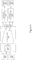
- FIG. 2 is a block diagram depicting an example network 200 for generating novel views according to the techniques disclosed herein.
- One existing view synthesis method utilizing deep convolutional neural networks estimates an appearance flow (e.g., dense point correspondences) between each of two input images and the target view as a two-dimensional flow field that can be adopted to reconstruct the target view.
- the main problem of that method is the geometric shape consistency is not considered in the process of generating the appearance flows.
- the network 200 models the dense point correspondences between the two rectified representations of two input images.
- the network 200 only has to estimate one-dimensional dense point correspondences instead of two-dimensional correspondences, which makes the correspondence estimation problem easier and thus makes the network 200 estimate the dense point correspondences more accurately.
- the network 200 thus includes an architecture which can automatically learn the rectified views of image pairs and the one-dimensional dense point correspondences within them.
- the network 200 takes image 202a and 202b as inputs to a rectification network 204 and generates rectified images 206a and 206b which are used as inputs to the encoder network 208.
- the encoder network 208 encodes the rectified images 206 using convolutional layers to generate a set of image features.
- the image features are used by the decoder network 210 to generate one-dimensional dense point correspondences and blending masks.
- the view morphing network 212 uses the one-dimensional dense point correspondences, the blending masks, and the rectified images 206 to generate the output image 214.
- the network 200 network does not have viewpoint transformation information as an input as current view synthesis methods do. Instead, the techniques introduced herein allow the network 200 to learn homography transformations used to rectify two input images without viewpoint transformation information within the network 200. Test results have shown that the network 200 without viewpoint transformation information performs better than the prior method with viewpoint transformation information.
- Some benefits of the unique architecture of network 200 include the following: 1) the unique one-dimensional dense point correspondences synthesize higher-quality images than typical two-dimensional dense point correspondences, which suffer from geometric shape distortions. This improvement is due to the geometric constraint that is imposed by the automatic rectification of the two input images by the network 200 that limits the correspondence search between the rectified image pairs to a one-dimensional search; 2) the network 200 does not require viewpoint transformation information as an input; 3) the network 200 can synthesize infinite image views between the two input images based on the estimated dense point correspondences and blending masks.
- image 202a and image 202b pass through a rectification network 204.
- the rectification network 204 learns two projective transformation matrices (i.e., homographies that are invertible 3 x 3 real matrices) and warps image pairs with the projective transform matrices.
- FIG. 3 is a block diagram depicting an example rectification network according to the techniques disclosed herein.
- the rectification network 204 includes convolutional layers 302 that receive a stack of image 202a and image 202b as inputs.
- the convolutional layers 302 generate a homography transformation matrix 304a for image 202a and a homography transformation matrix 304b for image 202b.
- the homography transform matrix 304a is used by homography transformation layer 306a to warp image 202a and generate rectified image 206a
- homography transform matrix 304b is used by homography transformation layer 306b to warp image 202b to generate rectified image 206b.
- Figure 4 is a block diagram depicting another example rectification network according to the techniques disclosed herein.
- image 202a is processed through convolutional layers 404a to generate a set of features 404a corresponding to image 202a.
- image 202b is processed through convolutional layers 404b to generate a set of features 404b corresponding to image 202b.
- the features 404a and 404b are combined and processed by convolutional layers 406a and convolutional layers 406b to generate a homography transformation matrix 408a and homography transformation matrix 408b.
- Homography transformation layer 410a processes image 202a using the homography transform matrix 408a to generate rectified image 206a
- homography transformation layer 410b processes image 202b to generate rectified image 206b.
- Figure 5 is a block diagram depicting an example encoder network 208 according to the techniques disclosed herein.
- the encoder network 208 takes a stack of rectified image 206a and rectified image 206b and encodes those images as a set of features 504 using convolutional layers 502.
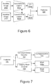
- Figure 6 is a block diagram depicting an example encoder network 208 according to the techniques disclosed herein.
- encoder network 208 includes two convolutional layers 602a and 602b with shared weights between the two encoders for two rectified images as depicted in the example of Figure 6 .
- Output features 604a and 604b of the convolutional layers 602a and 602b are concatenated to encode the viewpoint transformation between the input images as a set of feature 606.
- Figure 7 is a block depicting an example decoder network according to the techniques disclosed herein.
- the decoder network takes a set of feature 701 from an encoder network (e.g., the encoder networks depicted in Figures 5 and 6 ) and decodes the feature 701 using a correspondence decoder 702 to generate dense point correspondences 706 between the two rectified images 206a and 206b.
- a visibility mask decoder 704 uses the features 701 to generate blending masks 708a and 708b that are used by the view morphing network 214 in synthesizing the output image 214.
- the masks 708a and 708b take into account the portions of the input images that may be hidden or visible in the output image 214 but are visible (or not visible) in one or more of the input views.
- a preliminary output of the view morphing network is multiplied by the blending masks to provide an output that is more in line with the shape of the input views.
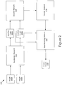
- Figure 8 is a block diagram depicting an example view morphing network according to the techniques disclosed herein.
- the view morphing network 212 uses the output dense point correspondences 706 of the decoder network 210 and the rectified images 206a and 206b, the view morphing network 212 generates output image 214 that is a middle view between the rectified images 206a and 206b.
- C(q) denote the output 706 of the correspondence decoder 702 where q is the pixel coordinates of the middle view to be synthesized.
- R m M 1 ⁇ R 1 P 1 + M 2 ⁇ R 2 P 2 , where ⁇ represents element-wise multiplication and R 1 ( P 1 ) and R 2 ( P 2 ) are images sampled from R 1 and R 2 by interpolation.
- View morphing network 212 as depicted in the example of Figure 8 , includes a sampling 802a of rectified image 206a using the dense correspondences 706 and a sampling 802b of rectified image 206b using the dense correspondences to generate sampled images 804a and 804b, respectively..
- the view morphing network 212 blends 806 the sampled images 804a and 804b with the blending masks 708a and 708b to finally synthesize the output image 214.
- the network 200 is trained using two input image views, image 202a and image 202b, and the corresponding desired ground truth middle view image.
- Figure 9 is a block diagram depicting an example process for generating a novel view according to the techniques disclosed herein.
- the network 200 receives a first image depicting a first view of an object.
- the network 200 receives image 202a.
- the network 200 receives a second image depicting a second view of the object (e.g., image 202b).
- the first image 202a and the second image 202b may depict an object, for example, from a right perspective view and a left perspective view corresponding to the first and second view of the object depicted in the images 202a and 202b.
- a rectification network 204 rectifies the first image and the second image to generate a first rectified image and a second rectified image. As described above, rectifying the first image and the second image simplifies the remaining steps in the view synthesis process by limiting correspondence estimation to a one-dimensional search.
- an encoder network 208 encodes the first and second rectified images (e.g., rectified images 206a and 206b) to generate convolutional neural network features and at 910 a decoder network 210 processes the convolutional neural network features to generate a correspondence between pixels of the first rectified image and pixels of the second rectified image, and blending masks that represents the visibility of pixels of the rectified images in the synthesized middle view.
- first and second rectified images e.g., rectified images 206a and 206b
- a decoder network 210 processes the convolutional neural network features to generate a correspondence between pixels of the first rectified image and pixels of the second rectified image, and blending masks that represents the visibility of pixels of the rectified images in the synthesized middle view.
- the view morphing network 212 synthesizes the novel middle view output using the correspondence between pixels of the first rectified image and pixels of the second rectified image, and the blending masks.
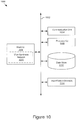
- FIG 10 is a block diagram of an example computing system 1000, which may represent the computer architecture of a computing device, computing entity, or server for implementing the view synthesis network 200.
- the computing system 1000 may include a communication unit 1004, a processor(s) 1008, a memory(ies) 1018, a data store 1012, and/or an input/output device(s) 1014, connected by a communication bus 1002, depending on the configuration.
- the computing system 1000 depicted in Figure 10 is provided by way of example and it should be understood that it may take other forms and include additional or fewer components without departing from the scope of the present disclosure.
- various components of the computing devices may be coupled for communication using a variety of communication protocols and/or technologies including, for instance, communication buses, software communication mechanisms, computer networks, etc.
- the computing system 1000 may include various operating systems, sensors, additional processors, and other physical configurations.
- Figure 10 only shows a single communication unit 1004, processor 1008, data store 1012, input/output device 1014, and memory 1018, it should be understood that the computing system 1000 may include none or a plurality of one or more of these components.
- the bus 1002 may include a communication bus for transferring data between components of a computing device or between computing devices, a network bus system, a processor mesh, a combination thereof, etc.
- the communication bus can include and/or facilitate, for example, inter-method communication, local function or procedure calls, remote procedure calls, an object broker (e.g., CORBA), direct socket communication (e.g., TCP/IP sockets) among software modules, UDP broadcasts and receipts, HTTP connections, etc. Further, any or all of the communication could be secure (e.g., SSH, HTTPS, etc.).
- the communication unit 1004 may include one or more interface devices (I/F) for wired and wireless connectivity among a larger network of computing entities.
- the communication unit 1004 may include, but is not limited to, various types known connectivity and interface options.
- the communication unit 1004 may be coupled to the other components of the computing system 1000 via the bus 1002.
- the communication unit 404 can provide other connections to a network and to other entities using various standard communication protocols or proprietary communication protocols, as described elsewhere herein.
- the processor 1008 may execute software instructions by performing various input, logical, and/or mathematical operations.
- the processor 1008 may have various computing architectures including, for example, a complex instruction set computer (CISC) architecture, a reduced instruction set computer (RISC) architecture, and/or an architecture implementing a combination of instruction sets.
- the processor 1008, which may include one or more processors, may be physical and/or virtual, and may include a single core or plurality of processing units and/or cores.
- the processor 1008 may be capable of generating and providing electronic display signals to a display device, supporting the display of images, capturing and transmitting images, performing complex tasks including various types of feature extraction and sampling, etc.
- the processor 1008 may be coupled to the memory 1018 via the bus 1002 to access data and instructions therefrom and store data therein.
- the memory(ies) 1018 may store and provide access to data to the other components of the computing system 1000.
- the memory 1018 may be included in a single computing device or a plurality of computing devices.
- the memory 1018 may store instructions and/or data that may be executed by the processor 1008.
- the memory 1018 may store view morphing network 1020.
- the memory 1018 is also capable of storing other instructions and data, including, for example, an operating system, hardware drivers, other software applications, databases, etc.
- the memory 1018 may be coupled to the bus 402 for communication with the processor 1008 and the other components of computing system 1000.
- the memory 1018 may include a non-transitory computer-usable (e.g., readable, writeable, etc.) medium, which can be any non-transitory apparatus or device that can contain, store, communicate, propagate or transport instructions, data, computer programs, software, code, routines, etc., for processing by or in connection with the processor 1008.
- the memory 1016 may include one or more of volatile memory and non-volatile memory (e.g., RAM, ROM, hard disk, optical disk, etc.). It should be understood that the memory 1016 may be a single device or may include multiple types of devices and configurations.
- the view morphing network 1020 can be implemented using programmable or specialized hardware including a field-programmable gate array (FPGA) or an application-specific integrated circuit (ASIC). In some implementations, the view morphing network 1020 can be implemented using a combination of hardware and software executable by processor 1008. In some implementations, the view morphing network 1020 may be sets of instructions executable by the processor 1008.
- FPGA field-programmable gate array
- ASIC application-specific integrated circuit
- the data store 1012 is an information source for storing and providing access to data.
- the data stored by the data store 1012 may organized and queried using various criteria including any type of data stored by them.
- the data store 1012 may include data tables, databases, or other organized collections of data.
- the input/output device(s) 1014 may include any device for inputting or outputting information into the computing system 1000.
- the input/output device(s) 1014 may include one or more input devices, such as a keyboard, a pointing device, microphone, an image/video capture device (e.g., camera), a touch-screen display, etc.
- the input/output device(s) 1014 may include one or more output devices, such as one or more of a display (LCD, OLED, etc.), a printer, a haptic device, audio reproduction device, touch-screen display, etc.
- the output device is a display, which may display electronic images and data output by the computing system 1000 for presentation to a user.
- the computing system 1000 may include a graphics adapter (not shown) for rendering and outputting the images and data for presentation on an output device.
- the graphics adapter may be a separate processing device including a separate processor and memory (not shown) or may be integrated with the processor 1008 and memory 1018.
Landscapes
- Engineering & Computer Science (AREA)
- Physics & Mathematics (AREA)
- Theoretical Computer Science (AREA)
- General Physics & Mathematics (AREA)
- General Health & Medical Sciences (AREA)
- General Engineering & Computer Science (AREA)
- Biophysics (AREA)
- Computational Linguistics (AREA)
- Data Mining & Analysis (AREA)
- Evolutionary Computation (AREA)
- Artificial Intelligence (AREA)
- Molecular Biology (AREA)
- Computing Systems (AREA)
- Biomedical Technology (AREA)
- Life Sciences & Earth Sciences (AREA)
- Mathematical Physics (AREA)
- Software Systems (AREA)
- Health & Medical Sciences (AREA)
- Computer Vision & Pattern Recognition (AREA)
- Image Processing (AREA)
- Image Generation (AREA)
Abstract
Description
- The present specification generally relates to the field of view synthesis and more particularly to novel view synthesis using deep convolutional neural networks.
- Novel view synthesis has practical applications, mostly in computer vision and virtual reality. For example, using computer vision to recognize an object in an image, it may be helpful to obtain images of the object in all possible different views. With limited images of the object in different views, view synthesis methods can generate images that depict the object in views not in the original images. Additionally, view synthesis may be used to create full virtual reality environments based on limited images or video footage. Recently, learning-based techniques utilizing deep convolutional neural networks have been successfully applied to the view synthesis problems. However, such techniques usually suffer from lack of texture details, geometric shape distortions, or excessive computational complexity.
- The techniques introduced herein overcome the deficiencies and limitations of the prior art, at least in part, with a system and method for generating novel views of an image using deep convolutional neural networks. To generate the middle view, a rectification network rectifies the two images and an encoder network encodes the two rectified images to generate convolutional neural network features. The convolutional neural network features are fed to a decoder network that decodes the features to generate dense point correspondences between the two rectified images and blending masks. Using the correspondence between the two rectified images and blending masks, a view morphing network morphs the two images to generate an intermediate view image depicting an object in the two images in a view between the two images.
- Other aspects include corresponding methods, systems, apparatuses, and computer program products for these and other innovative aspects.
- The features and advantages described herein are not all-inclusive and many additional features and advantages will be apparent to one of ordinary skill in the art in view of the figures and description. Moreover, it should be noted that the language used in the specification has been principally selected for readability and instructional purposes and not to limit the scope of the techniques described.
- The disclosure is illustrated by way of example, and not by way of limitation in the figures of the accompanying drawings in which like reference numerals are used to refer to similar elements.
-
Figure 1A is an example depicting two images from which a novel view is generated. -
Figure 1B is an example depicting a novel view generated from the example images ofFigure 1A . -
Figure 2 is a block diagram depicting an example network for generating novel views according to the techniques disclosed herein. -
Figure 3 is a block diagram depicting an example rectification network according to the techniques disclosed herein. -
Figure 4 is a block diagram depicting an example rectification network according to the techniques disclosed herein. -
Figure 5 is a block diagram depicting an example encoder network according to the techniques disclosed herein. -
Figure 6 is a block diagram depicting an example encoder network according to the techniques disclosed herein. -
Figure 7 is a block diagram depicting an example decoder network according to the techniques disclosed herein. -
Figure 8 is a block diagram depicting an example view morphing network according to the techniques disclosed herein. -
Figure 9 is a block diagram depicting an example process for generating a novel view according to the techniques disclosed herein. -
Figure 10 is a block diagram of an example computing system for implementing the network according to the techniques disclosed herein. - The systems and methods according to the techniques of this disclosure provide techniques for generating novel views of an image using deep convolutional neural networks.
- Currently, novel view synthesis is approached in two broad categories: geometry-based approaches and learning-based approaches. Geometric approaches first try to estimate the approximate underlying 3D structure of the object and then apply some transformation to the pixels in the input image to produce the output image. Besides the requirement of somehow estimating the 3D structure, the other major downside of geometric approaches is that they produce holes in places where the source image does not have sufficient visual content (e.g. the back side of an object). In such cases, various types of texture hole-filling may be used but the hole-filling techniques are not always effective.
- Learning-based approaches, on the other hand, use more information from input images to generate a novel view. For example, given a side view of a car, there is no way to guess what the front of the car looks like, unless the system has observed other fronts of cars to make an educated guess. Learning based approaches typically use training images to build a parametric model of the object class and then use the parametric model, together with the input image, to generate a novel view. However, results from parametric image generation are often too blurry.
- View morphing can generate shape-preserving view synthesis results. View morphing can be thought of as three steps: (i) rectification, (ii) view synthesis by interpolation, and (iii) post-warping. Two input images, I 1 and I 2, are rectified by applying homographies H 1 and H 2 to I 1 and I 2, respectively, to align corresponding points of the two images on the same row. Such homographies can be computed from the fundamental matrix obtained from seven or more point correspondences between the images. The rectified image pair R 1 and R 2 can be viewed as captured from two parallel view cameras and linear interpolation of parallel views yields shape-preserving view synthesis results. Novel view images can be synthesized by linearly interpolating position and colors of corresponding points of R 1 and R 2. As the image pair is already rectified, such synthesis can be done on a row by row basis. Let



- The techniques introduced herein generate a novel view by explicitly modeling geometric constraints between image pairs. The techniques include generating rectified representations of two input images within a view synthesis problem and producing dense point correspondences between the rectified representations of the two input images. Since the input images are rectified, the correspondence searching is simplified to a one-dimensional estimation problem. This makes the correspondence estimation problem significantly easier and less computationally intensive than existing methods. The techniques introduced herein use the one-dimensional dense point correspondences to generate an output image together with blending masks to explicitly model visibility of pixels in the output image. The techniques introduced herein produce results with less geometric shape distortion and clearer texture details while being less computationally extensive than existing methods.
- For the purposes of this disclosure, reference numbers may be used to refer to components found in any of the figures, regardless of whether those reference numbers are shown in the figure being described. Further, where a reference number includes a letter referring to one of multiple similar components (e.g., component 000a, 000b, and 000n), the reference number may be used without the letter to refer to one or all of the similar components.
-
Figure 1A is an example depicting two images from which a novel view is generated. In the example ofFigure 1A , animage 102a of a chair is depicted from a left view and animage 102b of the chair is depicted from a right view. As described above, the techniques introduced herein provide for generating a novel view of an image given two views such as those depicted inFigure 1A. Figure 1B is an example depicting anovel view 104 generated from the example chair images ofFigure 1A using the techniques introduced herein. -
Figure 2 is a block diagram depicting anexample network 200 for generating novel views according to the techniques disclosed herein. One existing view synthesis method utilizing deep convolutional neural networks estimates an appearance flow (e.g., dense point correspondences) between each of two input images and the target view as a two-dimensional flow field that can be adopted to reconstruct the target view. The main problem of that method is the geometric shape consistency is not considered in the process of generating the appearance flows. In contrast, thenetwork 200 models the dense point correspondences between the two rectified representations of two input images. As a result of the rectification, thenetwork 200 only has to estimate one-dimensional dense point correspondences instead of two-dimensional correspondences, which makes the correspondence estimation problem easier and thus makes thenetwork 200 estimate the dense point correspondences more accurately. Thenetwork 200 thus includes an architecture which can automatically learn the rectified views of image pairs and the one-dimensional dense point correspondences within them. - As described in more detail with reference to the remaining figures, the
network 200 takesimage rectification network 204 and generates rectifiedimages encoder network 208. Theencoder network 208 encodes the rectified images 206 using convolutional layers to generate a set of image features. The image features are used by thedecoder network 210 to generate one-dimensional dense point correspondences and blending masks. Theview morphing network 212 uses the one-dimensional dense point correspondences, the blending masks, and the rectified images 206 to generate theoutput image 214. - It should be noted that the
network 200 network does not have viewpoint transformation information as an input as current view synthesis methods do. Instead, the techniques introduced herein allow thenetwork 200 to learn homography transformations used to rectify two input images without viewpoint transformation information within thenetwork 200. Test results have shown that thenetwork 200 without viewpoint transformation information performs better than the prior method with viewpoint transformation information. - Some benefits of the unique architecture of
network 200 include the following: 1) the unique one-dimensional dense point correspondences synthesize higher-quality images than typical two-dimensional dense point correspondences, which suffer from geometric shape distortions. This improvement is due to the geometric constraint that is imposed by the automatic rectification of the two input images by thenetwork 200 that limits the correspondence search between the rectified image pairs to a one-dimensional search; 2) thenetwork 200 does not require viewpoint transformation information as an input; 3) thenetwork 200 can synthesize infinite image views between the two input images based on the estimated dense point correspondences and blending masks. - As depicted in the
network 200 in the example ofFigure 2 ,image 202a andimage 202b pass through arectification network 204. To rectify the images, therectification network 204 learns two projective transformation matrices (i.e., homographies that are invertible 3 x 3 real matrices) and warps image pairs with the projective transform matrices. -
Figure 3 is a block diagram depicting an example rectification network according to the techniques disclosed herein. As depicted in the example ofFigure 3 , therectification network 204 includesconvolutional layers 302 that receive a stack ofimage 202a andimage 202b as inputs. Theconvolutional layers 302 generate ahomography transformation matrix 304a forimage 202a and ahomography transformation matrix 304b forimage 202b. Thehomography transform matrix 304a is used byhomography transformation layer 306a to warpimage 202a and generate rectifiedimage 206a andhomography transform matrix 304b is used byhomography transformation layer 306b to warpimage 202b to generate rectifiedimage 206b. -
Figure 4 is a block diagram depicting another example rectification network according to the techniques disclosed herein. In the example ofFigure 4 ,image 202a is processed throughconvolutional layers 404a to generate a set offeatures 404a corresponding to image 202a. Similarly,image 202b is processed throughconvolutional layers 404b to generate a set offeatures 404b corresponding to image 202b. Thefeatures convolutional layers 406a andconvolutional layers 406b to generate ahomography transformation matrix 408a andhomography transformation matrix 408b.Homography transformation layer 410a processesimage 202a using thehomography transform matrix 408a to generate rectifiedimage 206a andhomography transformation layer 410b processesimage 202b to generate rectifiedimage 206b. -
Figure 5 is a block diagram depicting anexample encoder network 208 according to the techniques disclosed herein. Theencoder network 208 takes a stack of rectifiedimage 206a and rectifiedimage 206b and encodes those images as a set offeatures 504 usingconvolutional layers 502.Figure 6 is a block diagram depicting anexample encoder network 208 according to the techniques disclosed herein. In one embodiment,encoder network 208 includes twoconvolutional layers Figure 6 . Output features 604a and 604b of theconvolutional layers feature 606. -
Figure 7 is a block depicting an example decoder network according to the techniques disclosed herein. The decoder network takes a set offeature 701 from an encoder network (e.g., the encoder networks depicted inFigures 5 and6 ) and decodes thefeature 701 using acorrespondence decoder 702 to generatedense point correspondences 706 between the two rectifiedimages visibility mask decoder 704 uses thefeatures 701 to generate blendingmasks view morphing network 214 in synthesizing theoutput image 214. Themasks output image 214 but are visible (or not visible) in one or more of the input views. In one embodiment, a preliminary output of the view morphing network is multiplied by the blending masks to provide an output that is more in line with the shape of the input views. -
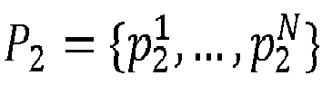
Figure 8 is a block diagram depicting an example view morphing network according to the techniques disclosed herein. Using the outputdense point correspondences 706 of thedecoder network 210 and the rectifiedimages view morphing network 212 generatesoutput image 214 that is a middle view between the rectifiedimages output 706 of thecorrespondence decoder 702 where q is the pixel coordinates of the middle view to be synthesized. Then the point correspondence sets

images 
masks visibility decoder 704 and R 1 and R 2 denote the two rectifiedimages 
network 212 as depicted in the example ofFigure 8 , includes asampling 802a of rectifiedimage 206a using thedense correspondences 706 and asampling 802b of rectifiedimage 206b using the dense correspondences to generate sampledimages view morphing network 212 blends 806 the sampledimages masks output image 214. - The
network 200 is trained using two input image views,image 202a andimage 202b, and the corresponding desired ground truth middle view image. The loss function used to train thenetwork 200 is the Euclidean loss between theoutput 214 and the ground truth image defined as:
- In some embodiments, where the assumption of a synthesized view that is centered between the two rectified
images 

images input images -
Figure 9 is a block diagram depicting an example process for generating a novel view according to the techniques disclosed herein. At 902, thenetwork 200 receives a first image depicting a first view of an object. For example, as depicted in the example ofFigure 2 , thenetwork 200 receivesimage 202a. At 904, thenetwork 200 receives a second image depicting a second view of the object (e.g.,image 202b). Thefirst image 202a and thesecond image 202b may depict an object, for example, from a right perspective view and a left perspective view corresponding to the first and second view of the object depicted in theimages - At 906, a
rectification network 204 rectifies the first image and the second image to generate a first rectified image and a second rectified image. As described above, rectifying the first image and the second image simplifies the remaining steps in the view synthesis process by limiting correspondence estimation to a one-dimensional search. - At 908, an
encoder network 208 encodes the first and second rectified images (e.g., rectifiedimages decoder network 210 processes the convolutional neural network features to generate a correspondence between pixels of the first rectified image and pixels of the second rectified image, and blending masks that represents the visibility of pixels of the rectified images in the synthesized middle view. - At 912, the
view morphing network 212 synthesizes the novel middle view output using the correspondence between pixels of the first rectified image and pixels of the second rectified image, and the blending masks. - It should be noted that the components and steps provided above are provided for illustration and that other components and processes are possible and contemplated in the techniques described herein. Further, the steps may be performed in different orders than those listed, additional or fewer steps are possible, and the steps and components performing the steps may be delineated differently than those of the provided examples.
-
Figure 10 is a block diagram of anexample computing system 1000, which may represent the computer architecture of a computing device, computing entity, or server for implementing theview synthesis network 200. As depicted inFigure 10 , thecomputing system 1000 may include acommunication unit 1004, a processor(s) 1008, a memory(ies) 1018, adata store 1012, and/or an input/output device(s) 1014, connected by acommunication bus 1002, depending on the configuration. Thecomputing system 1000 depicted inFigure 10 is provided by way of example and it should be understood that it may take other forms and include additional or fewer components without departing from the scope of the present disclosure. For instance, various components of the computing devices may be coupled for communication using a variety of communication protocols and/or technologies including, for instance, communication buses, software communication mechanisms, computer networks, etc. While not shown, thecomputing system 1000 may include various operating systems, sensors, additional processors, and other physical configurations. Although, for purposes of clarity,Figure 10 only shows asingle communication unit 1004,processor 1008,data store 1012, input/output device 1014, andmemory 1018, it should be understood that thecomputing system 1000 may include none or a plurality of one or more of these components. - The
bus 1002 may include a communication bus for transferring data between components of a computing device or between computing devices, a network bus system, a processor mesh, a combination thereof, etc. The communication bus can include and/or facilitate, for example, inter-method communication, local function or procedure calls, remote procedure calls, an object broker (e.g., CORBA), direct socket communication (e.g., TCP/IP sockets) among software modules, UDP broadcasts and receipts, HTTP connections, etc. Further, any or all of the communication could be secure (e.g., SSH, HTTPS, etc.). - The
communication unit 1004 may include one or more interface devices (I/F) for wired and wireless connectivity among a larger network of computing entities. For instance, thecommunication unit 1004 may include, but is not limited to, various types known connectivity and interface options. Thecommunication unit 1004 may be coupled to the other components of thecomputing system 1000 via thebus 1002. The communication unit 404 can provide other connections to a network and to other entities using various standard communication protocols or proprietary communication protocols, as described elsewhere herein. - The
processor 1008 may execute software instructions by performing various input, logical, and/or mathematical operations. Theprocessor 1008 may have various computing architectures including, for example, a complex instruction set computer (CISC) architecture, a reduced instruction set computer (RISC) architecture, and/or an architecture implementing a combination of instruction sets. Theprocessor 1008, which may include one or more processors, may be physical and/or virtual, and may include a single core or plurality of processing units and/or cores. In some implementations, theprocessor 1008 may be capable of generating and providing electronic display signals to a display device, supporting the display of images, capturing and transmitting images, performing complex tasks including various types of feature extraction and sampling, etc. In some implementations, theprocessor 1008 may be coupled to thememory 1018 via thebus 1002 to access data and instructions therefrom and store data therein. - The memory(ies) 1018 may store and provide access to data to the other components of the
computing system 1000. Thememory 1018 may be included in a single computing device or a plurality of computing devices. In some implementations, thememory 1018 may store instructions and/or data that may be executed by theprocessor 1008. For example, thememory 1018 may storeview morphing network 1020. Thememory 1018 is also capable of storing other instructions and data, including, for example, an operating system, hardware drivers, other software applications, databases, etc. Thememory 1018 may be coupled to the bus 402 for communication with theprocessor 1008 and the other components ofcomputing system 1000. - The
memory 1018 may include a non-transitory computer-usable (e.g., readable, writeable, etc.) medium, which can be any non-transitory apparatus or device that can contain, store, communicate, propagate or transport instructions, data, computer programs, software, code, routines, etc., for processing by or in connection with theprocessor 1008. In some implementations, the memory 1016 may include one or more of volatile memory and non-volatile memory (e.g., RAM, ROM, hard disk, optical disk, etc.). It should be understood that the memory 1016 may be a single device or may include multiple types of devices and configurations. - In some implementations, the
view morphing network 1020 can be implemented using programmable or specialized hardware including a field-programmable gate array (FPGA) or an application-specific integrated circuit (ASIC). In some implementations, theview morphing network 1020 can be implemented using a combination of hardware and software executable byprocessor 1008. In some implementations, theview morphing network 1020 may be sets of instructions executable by theprocessor 1008. - The
data store 1012 is an information source for storing and providing access to data. The data stored by thedata store 1012 may organized and queried using various criteria including any type of data stored by them. Thedata store 1012 may include data tables, databases, or other organized collections of data. - The input/output device(s) 1014 may include any device for inputting or outputting information into the
computing system 1000. For example, the input/output device(s) 1014 may include one or more input devices, such as a keyboard, a pointing device, microphone, an image/video capture device (e.g., camera), a touch-screen display, etc. The input/output device(s) 1014 may include one or more output devices, such as one or more of a display (LCD, OLED, etc.), a printer, a haptic device, audio reproduction device, touch-screen display, etc. In some implementations, the output device is a display, which may display electronic images and data output by thecomputing system 1000 for presentation to a user. In some implementations, thecomputing system 1000 may include a graphics adapter (not shown) for rendering and outputting the images and data for presentation on an output device. The graphics adapter (not shown) may be a separate processing device including a separate processor and memory (not shown) or may be integrated with theprocessor 1008 andmemory 1018. - It should be noted that the components described herein, for example, in reference to
Figure 10 may be further delineated or changed without departing from the techniques described herein. For example, the processes described throughout this disclosure may be performed by fewer, additional, or different components. The foregoing description has been presented for the purposes of illustration and description. It is not intended to be exhaustive or to limit the specification to the precise form disclosed. Many modifications and variations are possible in light of the above teaching. It is intended that the scope of the disclosure be limited not by this detailed description, but rather by the claims of this application. As will be understood by those familiar with the art, the specification may be embodied in other specific forms without departing from the spirit or essential characteristics thereof. Likewise, the particular naming and division of the modules, routines, features, attributes, methodologies and other aspects may not be mandatory or significant, and the mechanisms that implement the specification or its features may have different names, divisions and/or formats.
Claims (15)
- A method comprising:receiving a first image depicting a first view of an object;receiving a second image depicting a second view of the object;rectifying the first image and the second image to generate a first rectified image and a second rectified image;encoding the first and second rectified images to generate a plurality of convolutional neural network features;processing the plurality of convolutional neural network features to generate a correspondence between pixels of the first rectified image and pixels of the second rectified image; andsynthesizing an output image using the correspondence between pixels of the first rectified image and the pixels of the second rectified image, wherein the output image is an intermediate view image depicting the object in a view between the first view and the second view.
- The method of claim 1, further comprising:processing the plurality of convolutional neural network features to generate blending masks to predict visibility of pixels of the first rectified image and the second rectified image in the output image, wherein synthesizing the output image includes using the blending masks.
- The method of claim 1, wherein rectifying the first image and the second image further comprises:generating a first homography transformation matrix based on the first image and the second image;generating a second homography transformation matrix for the second image based on the first image and the second image;warping the first image, using the first homography transformation matrix, to generate the first rectified image; andwarping the second image, using the second homography transformation matrix, to generate the second rectified image.
- The method of claim 1, wherein rectifying the first image and the second image further comprises:generating a first set of features for the first image;generating a second set of features for the second image;fusing the first set of feature and the second set of features to generate a set of fused features for the first and second image;generating a first homography transformation matrix using the set of fused features for the first and second image, wherein the first homography transformation matrix corresponds to the first image;generating a second homography transformation matrix using the set of fused features for the first and second image, wherein the second homography transformation matrix corresponds to the second image;warping the first image, using the first homography transformation matrix, to generate the first rectified image; andwarping the second image, using the second homography transformation matrix, to generate the second rectified image.
- The method of claim 1, wherein encoding the first and second rectified images comprises:encoding the first rectified image to generate a first set of convolutional neural network features;encoding the second rectified image to generate a second set of convolutional neural network features; andfusing the first set of convolutional neural network features and the second set of convolutional neural network features to generate the plurality of convolutional neural network features.
- The method of claim 1, wherein the correspondence between pixels is one-dimensional.
- The method of claim 1, wherein synthesizing the output image comprises:performing a linear interpolation of pixel values, blending mask values, and locations of corresponding pixels between the first rectified image and the second rectified image.
- A system comprising:one or more processors; anda memory, the memory storing instructions, which when executed by the one or more processors, cause the one or more processors to:receive a first image depicting a first view of an object;receive a second image depicting a second view of the object;rectify the first image and the second image to generate a first rectified image and a second rectified image;encode the first and second rectified images to generate a plurality of convolutional neural network features;process the plurality of convolutional neural network features to generate a correspondence between pixels of the first rectified image and pixels of the second rectified image; andsynthesize an output image using the correspondence between pixels of the first rectified image and the pixels of the second rectified image,wherein the output image is an intermediate view image depicting the object in a view between the first view and the second view.
- The system of claim 8, wherein the instructions further cause the one or more processors to:process the plurality of convolutional neural network features to generate blending masks to predict visibility of pixels of the first rectified image and the second rectified image in the output image, wherein to synthesize the output image, the one or more processors use the blending masks to generate the output image.
- The system of claim 8, wherein to rectify the first image and the second image, the instructions further cause the one or more processors to:generate a first homography transformation matrix based on the first image and the second image;generate a second homography transformation matrix for the second image based on the first image and the second image;warp the first image, using the first homography transformation matrix, to generate the first rectified image; andwarp the second image, using the second homography transformation matrix, to generate the second rectified image.
- The system of claim 8, wherein to rectify the first image and the second image, the instructions further cause the one or more processors to:generate a first set of features for the first image;generate a second set of features for the second image;fuse the first set of feature and the second set of features to generate a set of fused features for the first and second image;generate a first homography transformation matrix using the set of fused features for the first and second image, wherein the first homography transformation matrix corresponds to the first image;generate a second homography transformation matrix using the set of fused features for the first and second image, wherein the second homography transformation matrix corresponds to the second image;warp the first image, using the first homography transformation matrix, to generate the first rectified image; andwarp the second image, using the second homography transformation matrix, to generate the second rectified image.
- The system of claim 8, wherein to encode the first and second rectified images, the instructions further cause the one or more processors to:encode the first rectified image to generate a first set of convolutional neural network features;encode the second rectified image to generate a second set of convolutional neural network features; andfuse the first set of convolutional neural network features and the second set of convolutional neural network features to generate the plurality of convolutional neural network features.
- The system of claim 8, wherein the correspondence between pixels is one-dimensional.
- The system of claim 8, wherein to synthesize intermediate views, the instructions cause the one or more processors to:perform a linear interpolation of pixel values, blending mask values, and locations of corresponding pixels between the first rectified image and the second rectified image.
- A non-transitory computer readable medium storing instructions which, when executed by a computer, cause the computer to perform the method of any one of claims 1 to 7.
Applications Claiming Priority (1)
| Application Number | Priority Date | Filing Date | Title |
|---|---|---|---|
| US15/351,340 US10846836B2 (en) | 2016-11-14 | 2016-11-14 | View synthesis using deep convolutional neural networks |
Publications (1)
| Publication Number | Publication Date |
|---|---|
| EP3321881A1 true EP3321881A1 (en) | 2018-05-16 |
Family
ID=60301826
Family Applications (1)
| Application Number | Title | Priority Date | Filing Date |
|---|---|---|---|
| EP17200806.2A Withdrawn EP3321881A1 (en) | 2016-11-14 | 2017-11-09 | Novel view synthesis using deep convolutional neural networks |
Country Status (4)
| Country | Link |
|---|---|
| US (1) | US10846836B2 (en) |
| EP (1) | EP3321881A1 (en) |
| JP (2) | JP6471780B2 (en) |
| CA (1) | CA2985045A1 (en) |
Cited By (3)
| Publication number | Priority date | Publication date | Assignee | Title |
|---|---|---|---|---|
| CN109685750A (en) * | 2018-12-14 | 2019-04-26 | 厦门美图之家科技有限公司 | Image enchancing method and calculating equipment |
| GB2603983A (en) * | 2020-08-25 | 2022-08-24 | Nvidia Corp | View generation using one or more neural networks |
| US12367546B2 (en) | 2019-12-24 | 2025-07-22 | Nvidia Corporation | Panorama generation using one or more neural networks |
Families Citing this family (23)
| Publication number | Priority date | Publication date | Assignee | Title |
|---|---|---|---|---|
| US10163250B2 (en) | 2016-03-25 | 2018-12-25 | Outward, Inc. | Arbitrary view generation |
| US11989821B2 (en) | 2016-03-25 | 2024-05-21 | Outward, Inc. | Arbitrary view generation |
| US10163249B2 (en) | 2016-03-25 | 2018-12-25 | Outward, Inc. | Arbitrary view generation |
| US11232627B2 (en) | 2016-03-25 | 2022-01-25 | Outward, Inc. | Arbitrary view generation |
| US11972522B2 (en) | 2016-03-25 | 2024-04-30 | Outward, Inc. | Arbitrary view generation |
| US11989820B2 (en) | 2016-03-25 | 2024-05-21 | Outward, Inc. | Arbitrary view generation |
| US11222461B2 (en) | 2016-03-25 | 2022-01-11 | Outward, Inc. | Arbitrary view generation |
| GB2563004A (en) * | 2017-05-23 | 2018-12-05 | Nokia Technologies Oy | Methods and apparatuses for handling visual virtual reality content |
| US10762359B2 (en) * | 2017-08-31 | 2020-09-01 | Nec Corporation | Computer aided traffic enforcement using dense correspondence estimation with multi-level metric learning and hierarchical matching |
| JP7179515B2 (en) * | 2018-07-13 | 2022-11-29 | キヤノン株式会社 | Apparatus, control method and program |
| US11064180B2 (en) * | 2018-10-15 | 2021-07-13 | City University Of Hong Kong | Convolutional neural network based synthesized view quality enhancement for video coding |
| CN109472360B (en) * | 2018-10-30 | 2020-09-04 | 北京地平线机器人技术研发有限公司 | Update method, update device and electronic device of neural network |
| KR102641423B1 (en) * | 2018-12-11 | 2024-02-28 | 삼성전자주식회사 | Image processing apparatus and operating method for the same |
| CN110197458B (en) * | 2019-05-14 | 2023-08-01 | 广州视源电子科技股份有限公司 | Training method and device for visual angle synthesis network, electronic equipment and storage medium |
| CN110689514B (en) * | 2019-10-11 | 2022-11-11 | 深圳大学 | Training method and computer equipment for new visual angle synthetic model of transparent object |
| KR20220074959A (en) * | 2019-11-08 | 2022-06-03 | 아웃워드, 인코포레이티드 | arbitrary view creation |
| CN110798673B (en) * | 2019-11-13 | 2021-03-19 | 南京大学 | Free viewpoint video generation and interaction method based on deep convolutional neural network |
| JP7427467B2 (en) * | 2020-02-14 | 2024-02-05 | キヤノン株式会社 | Image processing device, image processing method, trained model generation method, and program |
| JP7386888B2 (en) | 2020-10-08 | 2023-11-27 | グーグル エルエルシー | Two-shot composition of the speaker on the screen |
| CN115529835A (en) * | 2021-04-08 | 2022-12-27 | 谷歌有限责任公司 | Neural Hybrid for Novel View Synthesis |
| CN113077401B (en) * | 2021-04-09 | 2022-06-24 | 浙江大学 | Method for stereo correction by viewpoint synthesis technology |
| JP7638194B2 (en) * | 2021-10-29 | 2025-03-03 | 株式会社日立製作所 | Design device and design method |
| WO2025046779A1 (en) * | 2023-08-30 | 2025-03-06 | 日本電気株式会社 | Image processing device, image processing method, and program |
Citations (2)
| Publication number | Priority date | Publication date | Assignee | Title |
|---|---|---|---|---|
| US6724417B1 (en) * | 2000-11-29 | 2004-04-20 | Applied Minds, Inc. | Method and apparatus maintaining eye contact in video delivery systems using view morphing |
| EP2389006A2 (en) * | 2010-05-20 | 2011-11-23 | Sony Corporation | A system and method of image processing |
Family Cites Families (10)
| Publication number | Priority date | Publication date | Assignee | Title |
|---|---|---|---|---|
| WO1995006297A1 (en) | 1993-08-27 | 1995-03-02 | Massachusetts Institute Of Technology | Example-based image analysis and synthesis using pixelwise correspondence |
| JP5184824B2 (en) * | 2007-06-15 | 2013-04-17 | キヤノン株式会社 | Arithmetic processing apparatus and method |
| US8503539B2 (en) | 2010-02-26 | 2013-08-06 | Bao Tran | High definition personal computer (PC) cam |
| US8873813B2 (en) | 2012-09-17 | 2014-10-28 | Z Advanced Computing, Inc. | Application of Z-webs and Z-factors to analytics, search engine, learning, recognition, natural language, and other utilities |
| CN103493093B (en) * | 2011-11-17 | 2017-07-18 | 松下知识产权经营株式会社 | Image processing apparatus, camera device and image processing method |
| US9430834B2 (en) * | 2014-01-20 | 2016-08-30 | Nokia Corporation | Visual perception matching cost on binocular stereo images |
| KR102265109B1 (en) * | 2014-01-24 | 2021-06-15 | 삼성전자주식회사 | Method and apparatus for image processing |
| EP3086279A1 (en) * | 2015-04-24 | 2016-10-26 | KNORR-BREMSE Systeme für Nutzfahrzeuge GmbH | Image synthesizer for a driver assisting system |
| US10157452B1 (en) * | 2015-09-28 | 2018-12-18 | Amazon Technologies, Inc. | Image processing system for image rectification |
| US20170161607A1 (en) * | 2015-12-04 | 2017-06-08 | Pilot Ai Labs, Inc. | System and method for improved gesture recognition using neural networks |
-
2016
- 2016-11-14 US US15/351,340 patent/US10846836B2/en not_active Expired - Fee Related
-
2017
- 2017-08-08 JP JP2017152835A patent/JP6471780B2/en not_active Expired - Fee Related
- 2017-11-09 CA CA2985045A patent/CA2985045A1/en not_active Abandoned
- 2017-11-09 EP EP17200806.2A patent/EP3321881A1/en not_active Withdrawn
-
2019
- 2019-01-24 JP JP2019009850A patent/JP2019079565A/en active Pending
Patent Citations (2)
| Publication number | Priority date | Publication date | Assignee | Title |
|---|---|---|---|---|
| US6724417B1 (en) * | 2000-11-29 | 2004-04-20 | Applied Minds, Inc. | Method and apparatus maintaining eye contact in video delivery systems using view morphing |
| EP2389006A2 (en) * | 2010-05-20 | 2011-11-23 | Sony Corporation | A system and method of image processing |
Non-Patent Citations (2)
| Title |
|---|
| FLYNN JOHN ET AL: "Deep Stereo: Learning to Predict New Views from the World's Imagery", 2016 IEEE CONFERENCE ON COMPUTER VISION AND PATTERN RECOGNITION (CVPR), IEEE, 27 June 2016 (2016-06-27), pages 5515 - 5524, XP033021748, DOI: 10.1109/CVPR.2016.595 * |
| ZHOU TINGHUI ET AL: "View Synthesis by Appearance Flow", 17 September 2016, ECCV 2016 CONFERENCE; [LECTURE NOTES IN COMPUTER SCIENCE; LECT.NOTES COMPUTER], SPRINGER INTERNATIONAL PUBLISHING, CHAM, PAGE(S) 286 - 301, ISBN: 978-3-642-33485-6, ISSN: 0302-9743, XP047355395 * |
Cited By (6)
| Publication number | Priority date | Publication date | Assignee | Title |
|---|---|---|---|---|
| CN109685750A (en) * | 2018-12-14 | 2019-04-26 | 厦门美图之家科技有限公司 | Image enchancing method and calculating equipment |
| US12367546B2 (en) | 2019-12-24 | 2025-07-22 | Nvidia Corporation | Panorama generation using one or more neural networks |
| GB2603983A (en) * | 2020-08-25 | 2022-08-24 | Nvidia Corp | View generation using one or more neural networks |
| US11783510B2 (en) | 2020-08-25 | 2023-10-10 | Nvidia Corporation | View generation using one or more neural networks |
| GB2603983B (en) * | 2020-08-25 | 2025-03-12 | Nvidia Corp | View generation using one or more neural networks |
| US12488509B1 (en) | 2020-08-25 | 2025-12-02 | Nvidia Corporation | View generation using one or more neural networks |
Also Published As
| Publication number | Publication date |
|---|---|
| JP6471780B2 (en) | 2019-02-20 |
| JP2018081672A (en) | 2018-05-24 |
| CA2985045A1 (en) | 2018-05-14 |
| JP2019079565A (en) | 2019-05-23 |
| US20180137611A1 (en) | 2018-05-17 |
| US10846836B2 (en) | 2020-11-24 |
Similar Documents
| Publication | Publication Date | Title |
|---|---|---|
| US10846836B2 (en) | View synthesis using deep convolutional neural networks | |
| CN114170290B (en) | Image processing method and related equipment | |
| EP1354292B1 (en) | Method and apparatus FOR DEVELOPING HIGH-RESOLUTION IMAGERY | |
| CN107484428B (en) | Methods for displaying objects | |
| CN112989904A (en) | Method for generating style image, method, device, equipment and medium for training model | |
| CN112862683B (en) | A Neighborhood Image Stitching Method Based on Elastic Registration and Grid Optimization | |
| WO2016030305A1 (en) | Method and device for registering an image to a model | |
| WO1995006297A1 (en) | Example-based image analysis and synthesis using pixelwise correspondence | |
| CN117252914B (en) | Training methods, devices, electronic equipment, and storage media for depth estimation networks | |
| CN106846467A (en) | Entity scene modeling method and system based on the optimization of each camera position | |
| CN110378250B (en) | Training method, device and terminal equipment for neural network for scene cognition | |
| JP7808135B2 (en) | Modular image interpolation method | |
| JP2023153534A (en) | Image processing apparatus, image processing method, and program | |
| CN116721019A (en) | Multi-camera video image stitching method based on deep learning | |
| Lan et al. | Development of a virtual reality teleconference system using distributed depth sensors | |
| EP2879090B1 (en) | Aligning ground based images and aerial imagery | |
| CN117893719A (en) | A surround view stitching method and system for adaptive vehicle body | |
| US20160086365A1 (en) | Systems and methods for the conversion of images into personalized animations | |
| US20250218109A1 (en) | Rendering Videos with Novel Views from Near-Duplicate Photos | |
| US12323571B2 (en) | Method of training a neural network configured for converting 2D images into 3D models | |
| CN106954060B (en) | A kind of three-dimensional video-frequency generation method and auxiliary filming apparatus towards smart phone | |
| Huang et al. | AFNet: Asymmetric fusion network for monocular panorama depth estimation | |
| CN113192208B (en) | Three-dimensional roaming method and device | |
| Schnyder et al. | Depth image based compositing for stereo 3D | |
| CN120047591B (en) | A method and system for fast processing naked eye 3D character photos |
Legal Events
| Date | Code | Title | Description |
|---|---|---|---|
| PUAI | Public reference made under article 153(3) epc to a published international application that has entered the european phase |
Free format text: ORIGINAL CODE: 0009012 |
|
| STAA | Information on the status of an ep patent application or granted ep patent |
Free format text: STATUS: REQUEST FOR EXAMINATION WAS MADE |
|
| 17P | Request for examination filed |
Effective date: 20171109 |
|
| AK | Designated contracting states |
Kind code of ref document: A1 Designated state(s): AL AT BE BG CH CY CZ DE DK EE ES FI FR GB GR HR HU IE IS IT LI LT LU LV MC MK MT NL NO PL PT RO RS SE SI SK SM TR |
|
| AX | Request for extension of the european patent |
Extension state: BA ME |
|
| RAP1 | Party data changed (applicant data changed or rights of an application transferred) |
Owner name: RICOH COMPANY, LTD. |
|
| STAA | Information on the status of an ep patent application or granted ep patent |
Free format text: STATUS: THE APPLICATION IS DEEMED TO BE WITHDRAWN |
|
| 18D | Application deemed to be withdrawn |
Effective date: 20210601 |