EP3321763A1 - A switching device for an agricultural vehicle - Google Patents
A switching device for an agricultural vehicle Download PDFInfo
- Publication number
- EP3321763A1 EP3321763A1 EP17198250.7A EP17198250A EP3321763A1 EP 3321763 A1 EP3321763 A1 EP 3321763A1 EP 17198250 A EP17198250 A EP 17198250A EP 3321763 A1 EP3321763 A1 EP 3321763A1
- Authority
- EP
- European Patent Office
- Prior art keywords
- switch
- switching device
- variable
- control
- vehicle
- Prior art date
- Legal status (The legal status is an assumption and is not a legal conclusion. Google has not performed a legal analysis and makes no representation as to the accuracy of the status listed.)
- Granted
Links
Images




Classifications
-
- G—PHYSICS
- G05—CONTROLLING; REGULATING
- G05G—CONTROL DEVICES OR SYSTEMS INSOFAR AS CHARACTERISED BY MECHANICAL FEATURES ONLY
- G05G9/00—Manually-actuated control mechanisms provided with one single controlling member co-operating with two or more controlled members, e.g. selectively, simultaneously
- G05G9/02—Manually-actuated control mechanisms provided with one single controlling member co-operating with two or more controlled members, e.g. selectively, simultaneously the controlling member being movable in different independent ways, movement in each individual way actuating one controlled member only
- G05G9/04—Manually-actuated control mechanisms provided with one single controlling member co-operating with two or more controlled members, e.g. selectively, simultaneously the controlling member being movable in different independent ways, movement in each individual way actuating one controlled member only in which movement in two or more ways can occur simultaneously
- G05G9/047—Manually-actuated control mechanisms provided with one single controlling member co-operating with two or more controlled members, e.g. selectively, simultaneously the controlling member being movable in different independent ways, movement in each individual way actuating one controlled member only in which movement in two or more ways can occur simultaneously the controlling member being movable by hand about orthogonal axes, e.g. joysticks
- G05G9/04785—Manually-actuated control mechanisms provided with one single controlling member co-operating with two or more controlled members, e.g. selectively, simultaneously the controlling member being movable in different independent ways, movement in each individual way actuating one controlled member only in which movement in two or more ways can occur simultaneously the controlling member being movable by hand about orthogonal axes, e.g. joysticks the controlling member being the operating part of a switch arrangement
- G05G9/04788—Manually-actuated control mechanisms provided with one single controlling member co-operating with two or more controlled members, e.g. selectively, simultaneously the controlling member being movable in different independent ways, movement in each individual way actuating one controlled member only in which movement in two or more ways can occur simultaneously the controlling member being movable by hand about orthogonal axes, e.g. joysticks the controlling member being the operating part of a switch arrangement comprising additional control elements
- G05G9/04792—Manually-actuated control mechanisms provided with one single controlling member co-operating with two or more controlled members, e.g. selectively, simultaneously the controlling member being movable in different independent ways, movement in each individual way actuating one controlled member only in which movement in two or more ways can occur simultaneously the controlling member being movable by hand about orthogonal axes, e.g. joysticks the controlling member being the operating part of a switch arrangement comprising additional control elements for rotary control around the axis of the controlling member
-
- G—PHYSICS
- G05—CONTROLLING; REGULATING
- G05G—CONTROL DEVICES OR SYSTEMS INSOFAR AS CHARACTERISED BY MECHANICAL FEATURES ONLY
- G05G1/00—Controlling members, e.g. knobs or handles; Assemblies or arrangements thereof; Indicating position of controlling members
- G05G1/01—Arrangements of two or more controlling members with respect to one another
-
- A—HUMAN NECESSITIES
- A01—AGRICULTURE; FORESTRY; ANIMAL HUSBANDRY; HUNTING; TRAPPING; FISHING
- A01B—SOIL WORKING IN AGRICULTURE OR FORESTRY; PARTS, DETAILS, OR ACCESSORIES OF AGRICULTURAL MACHINES OR IMPLEMENTS, IN GENERAL
- A01B76/00—Parts, details or accessories of agricultural machines or implements, not provided for in groups A01B51/00 - A01B75/00
-
- G—PHYSICS
- G05—CONTROLLING; REGULATING
- G05G—CONTROL DEVICES OR SYSTEMS INSOFAR AS CHARACTERISED BY MECHANICAL FEATURES ONLY
- G05G1/00—Controlling members, e.g. knobs or handles; Assemblies or arrangements thereof; Indicating position of controlling members
- G05G1/015—Arrangements for indicating the position of a controlling member
-
- G—PHYSICS
- G05—CONTROLLING; REGULATING
- G05G—CONTROL DEVICES OR SYSTEMS INSOFAR AS CHARACTERISED BY MECHANICAL FEATURES ONLY
- G05G1/00—Controlling members, e.g. knobs or handles; Assemblies or arrangements thereof; Indicating position of controlling members
- G05G1/02—Controlling members for hand actuation by linear movement, e.g. push buttons
-
- G—PHYSICS
- G05—CONTROLLING; REGULATING
- G05G—CONTROL DEVICES OR SYSTEMS INSOFAR AS CHARACTERISED BY MECHANICAL FEATURES ONLY
- G05G1/00—Controlling members, e.g. knobs or handles; Assemblies or arrangements thereof; Indicating position of controlling members
- G05G1/04—Controlling members for hand actuation by pivoting movement, e.g. levers
-
- G—PHYSICS
- G05—CONTROLLING; REGULATING
- G05G—CONTROL DEVICES OR SYSTEMS INSOFAR AS CHARACTERISED BY MECHANICAL FEATURES ONLY
- G05G1/00—Controlling members, e.g. knobs or handles; Assemblies or arrangements thereof; Indicating position of controlling members
- G05G1/08—Controlling members for hand actuation by rotary movement, e.g. hand wheels
Definitions
- the present invention relates to a switching device for an agricultural vehicle, and an agricultural vehicle having such a switching device.
- Agricultural or constructional vehicles are generally provided with a variety of vehicle components, e.g. front or rear hitches, loader devices, or other hydraulic or pneumatic circuits.
- vehicle components e.g. front or rear hitches, loader devices, or other hydraulic or pneumatic circuits.
- Such components can comprise a number of related control variables, e.g. a depth, height, and/or extension length of a component.
- US Patent No. US 7,654,359 describes a switching device designed for increased operator comfort, having adjustment wheels switches for the control of a component variable of the tractor, with further rocker switches provided forward of the adjustment wheels switches, the rocker switches for control of additional variables related to the tractor component.
- an operator can easily become confused as to which variables are controlled by which switches, which can often result in the operator mistakenly actuating the wrong component.
- an operator may be required to look directly at the switching device and possibly remove their hand from the switching device in order to see where the rocker switches are located. Such actions can serve to divert the operator's attention, and can result in increased risk of operator discomfort or error.
- a switching device for an agricultural vehicle comprising:
- first and second or primary and secondary switches which are commonly located, where a second switch is mounted on the body of a first switch, allows an operator to easily control first and second variables without repositioning their fingers or hand.
- first and second variables may be arranged as related control variables, such that an operator can easily identify that operation of the second switch results in control of a variable related to the variable which is controlled by the first switch.
- first and second switches may be provided as simple pushbutton or "on/off" switches, or the switches may be provided as having multiple states or as continuously-variable switches.
- the first switch comprises a rotary switch.
- adjustment of the first variable can be performed by rotation of the first switch along a rotary switch path, about a rotational axis.
- the rotary switch may comprise any suitable control device, e.g. an adjustment wheel, a scroll wheel, a switch dial.
- the first switch comprises an adjustment wheel, wherein the second switch is mounted on an outer rim of the adjustment wheel.
- Providing the second switch on an outer rim of an adjustment wheel allows for ease of access to the second switch, as the first switch is rotated.
- the second switch comprises at least one of the following: a pushbutton switch, a rocker switch, a toggle switch, a scroll wheel.
- the switching device comprises an upper first switch and a lower first switch, the upper and lower first switches provided as concentric rotary switches, the upper and lower first switches having respective upper and lower second switches carried thereon.
- the first switch comprises a rotatable disc, the disc rotatable about a central axis for control of the first variable
- a switching device wherein the second switch is provided by the adjustment of the planar angle of the first switch results in an operator being able to easily control the second variable, regardless of the rotational position of the rotatable disc.
- the switching device comprises an angle detector measuring the planar angle of the disc to the horizontal, for control of the second variable.
- the switching device is configured such that when the disc is parallel to the horizontal, the angle detector outputs a zero-crossing value.
- the first switch comprises a linear slide switch or linear shuttle switch.
- adjustment of the first variable can be performed by movement of the slide or shuttle switch along a linear path, wherein the second switch is provided as mounted on the shuttle or body of the first switch.
- an agricultural vehicle preferably an agricultural tractor, having at least one switching device as described above, and at least one vehicle component controlled by said at least one switching device.
- the first and second variables are related control parameters for control of the vehicle component, such that an operator can easily interpret the status of related control parameters based on the status of the first and second switches.
- the first variable controlled by the first switch sets an operating range for the vehicle component.
- the second variable controlled by the second switch operates the vehicle component within the operating range set by the first variable.
- Such an operating range may comprise a component depth control limit, a height limit, and/or a length limit for a component.
- the second switch controls a depth, height and/or length value of the component, within the limits of the operating range set by the first switch.
- a vehicle according to the invention in the form of an agricultural tractor is indicated at 110.
- the tractor 110 comprises front wheels 112 and rear wheels 114, a forward engine section 116 and a cab section 118.
- a rear linkage 120 is provided at the rear of the tractor 110, and a front linkage 122 is provided at the front of the tractor 110.
- the front and rear linkages 120,122 can be actuated or moved using associated hydraulic cylinders.
- Rear fenders 124 are provided to cover a portion of the rear wheels 114.
- an operator station 126 is provided within the cab 118.
- the operator station 126 comprises a user interface device 128 which is used to display information relating to tractor operation, and to control different elements of the tractor 110.
- the operator station 126 is provided with a control lever 130, which can be used to operate different elements of the tractor 110, e.g. hydraulic circuits, lifting systems, and/or to control the acceleration and steering of the tractor 110.
- the operator station 126 is further provided with a switching device 10, which can be provided as part of an arm rest 132 for an operator.
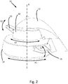
- a switching device 10 An enlarged view of a switching device 10 according to a first embodiment of the invention is provided in Figs. 2 and 3 .
- the switching device 10 comprises a housing part 12 having a dome-like shape intended for the resting of an operator's hand.
- the switching device 10 comprises a first or primary switch in the form of a lower adjustment wheel 14 arranged towards the base of the switching device 10.
- the adjustment wheel 14 is provided in a substantially horizontal alignment, and is arranged to be rotated about a central axis A, which extends through the top of the housing part 12.
- the adjustment wheel 14 is arranged to lie beneath the fingers of an operator having a hand resting on the housing part 12, such that the wheel 14 can be easily and comfortably adjusted by the operator.
- a second or secondary switch in the form of a rocker switch 16 is provided on the rim of the adjustment wheel 14, the rocker switch 16 carried by the adjustment wheel 14. Accordingly, as the adjustment wheel 14 is rotated about the central axis A, the rocker switch 16 is carried on the adjustment wheel 14. As a result, an operator can easily determine the position of the rocker switch 16 without looking at the switching device 10, by feeling for the switch 16 using their fingers.
- the first and second switches 14,16 can be configured to control related variables.
- the adjustment wheel 14 may be used to set a desired height, extension, or depth of a vehicle component such as a front or rear hitch, a front loader, etc.
- the rocker switch 16 can then be used to control a second variable for the same vehicle component, e.g. a rapid raising or lowering of a hitch or implement, or any other positional variable which may include height, extension, or depth.
- the adjustment wheel 14 may be used to set a desired operational range for a component, e.g. an upper permissible height for a front loader, where the associated rocker switch 16 is used to adjust a variable of the component within the desired range, i.e. the height of the front loader up to the upper permissible height set by the wheel 14.
- first and second switches 14,16 By configuring the first and second switches 14,16 to adjust different variables which are related to the control of the same vehicle component, as a result an operator can easily determine the relationship between the first and second switches 14,16 and actuate the switches 14,16 without looking at the switching device 10 or repositioning their hand.
- the rocker switch 16 can be positioned along the rim of the adjustment wheel 14 to act as an indicator or marker of the current variable value selected by rotation of the wheel 14.
- the rocker switch 16 is arranged such that it is moveable or actuatable in a different direction to the direction of rotation of the adjustment wheel 14, the rocker switch 16 actuatable in a substantially vertical direction as indicated by arrow Y1, the adjustment wheel 14 rotatable along a path indicated by arrow X1 substantially parallel to the horizontal axis. Providing switches 14,16 actuatable in different directions prevents inadvertent actuation of one switch while moving the other switch.
- the switching device 10 further comprises an upper adjustment wheel 18 arranged above the lower adjustment wheel 14, the upper adjustment wheel 18 having a reduced diameter compared to the lower adjustment wheel 14, and arranged parallel to and concentric with the lower adjustment wheel 14.
- the upper adjustment wheel 18 is used to control a first variable of a further vehicle component.
- an upper rocker switch 20 is provided on the outer rim of the upper adjustment wheel 18, for control of a further vehicle component variable, preferably a second variable related to the first variable controlled by the upper adjustment wheel 18.
- the switching device 10 may be configured to have any number of first and second switches, the second switches mounted or carried on the respective first switches.
- the upper rocker switch 20 is arranged such that it is moveable or actuatable in a different direction to the direction of rotation of the upper adjustment wheel 18, the rocker switch 20 actuatable in a substantially vertical direction as indicated by arrow Y2, the adjustment wheel 18 rotatable along a path indicated by arrow X2 substantially parallel to the horizontal axis.
- the relative movements of the different switching elements 14,16,18,20 can be seen in Fig. 3 , wherein the adjustment wheels 14,18 have been moved to set different values for the respective first variables, and wherein the rocker switches 16,20 can be controlled to adjust the values for the respective second variables.
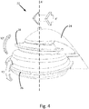
- a second embodiment of switching device according to the invention is indicated at 22.
- the switching device 22 comprises a housing part 24 having a dome-like shape intended for the resting of an operator's hand.
- the switching device 22 comprises a first switch in the form of a lower rotary disc 26 arranged towards the base of the switching device 22.
- the lower rotary disc 26 is arranged to be rotated about a central axis A', which extends through the top of the housing part 24.
- the direction of rotation of the disc 26 is indicated by arrow X', such that the rotary disc 26 can be used for control of a first variable of a vehicle.
- the rotary disc 26 is arranged along a plane substantially parallel to the horizontal.
- the rotary disc 26 is pivotally mounted in the switching device 22 such that the planar angle of the disc 26 is adjustable along the direction of the arrow Y1'.
- a second switch of the rotary disc 26 is provided in the form of an angle detector (not shown) which is arranged to measure the planar angle of the disc 26 to the horizontal, for control of a second variable of the vehicle.
- the second variable is a value for control of a vehicle component related to the component controlled by the rotation of the disc 26 along the path indicated by X'.
- the second embodiment of switching device 22 is provided with an upper rotary disc 28 arranged above and concentric with the lower rotary disc 26, and configured to be rotatable about the central axis A' as indicated by arrow X', for the control of a first variable of a further vehicle component.
- the upper rotary disc 28 is pivotally mounted in the switching device 22 such that the planar angle of the disc 28 is adjustable along the direction of the arrow Y2'. Adjustment of the planar angle is detected by a second switch in the form of an upper angle detector (not shown), for control of a second variable of the vehicle.
- a third embodiment of a switching device is indicated at 30.
- the switching device 30 is provided as part of an armrest 132 for a vehicle 110, a section of which is shown in Fig. 6 .
- the switching device 30 comprises a longitudinal rail 32 provided on the armrest 132.
- a first switch 34 is provided in the form of a linear slide or linear shuttle switch, wherein the output of the switch 34 is based on the position of the shuttle body of the switch 34 along the length of the rail 32, as indicated by arrow Z.
- the output of the first switch 34 provides a first variable used to control the operation of a component of the vehicle 110.
- a second switch 36 in the form of a rocker switch is provided on the side of the shuttle body of the switch 34, such that the second switch 36 is moved with the first switch 34 along the rail 32.
- the second switch 36 is used to output a second variable used to control the operation of a component of the vehicle 110.
- the switching device 30 is preferably configured such that the first and second switches 34,36 are used for the control of related variables, preferably for the adjustment of different variables used to control a particular vehicle component.
- Fig. 6 is further provided with an additional a linear slide or linear shuttle switch 38 moveable on the rail 32, the additional linear switch 38 having an additional rocker switch 40 provided on the side of the shuttle body of the switch 38, for the control of further first and second variables respectively.
- alternative configurations may comprise an array of linear slide or shuttle switches having secondary switched mounted thereon for control of a variety of vehicle variables, the array of switches provided on parallel rails arranged on an armrest 132 or as part of an operator station 126.
Landscapes
- Engineering & Computer Science (AREA)
- Physics & Mathematics (AREA)
- General Physics & Mathematics (AREA)
- Automation & Control Theory (AREA)
- Life Sciences & Earth Sciences (AREA)
- Mechanical Engineering (AREA)
- Soil Sciences (AREA)
- Environmental Sciences (AREA)
- Mechanical Control Devices (AREA)
- Vehicle Body Suspensions (AREA)
- Lifting Devices For Agricultural Implements (AREA)
Abstract
Description
- The present invention relates to a switching device for an agricultural vehicle, and an agricultural vehicle having such a switching device.
- Agricultural or constructional vehicles are generally provided with a variety of vehicle components, e.g. front or rear hitches, loader devices, or other hydraulic or pneumatic circuits. Such components can comprise a number of related control variables, e.g. a depth, height, and/or extension length of a component.
- US Patent No.
US 7,654,359 describes a switching device designed for increased operator comfort, having adjustment wheels switches for the control of a component variable of the tractor, with further rocker switches provided forward of the adjustment wheels switches, the rocker switches for control of additional variables related to the tractor component. However, an operator can easily become confused as to which variables are controlled by which switches, which can often result in the operator mistakenly actuating the wrong component. In addition, an operator may be required to look directly at the switching device and possibly remove their hand from the switching device in order to see where the rocker switches are located. Such actions can serve to divert the operator's attention, and can result in increased risk of operator discomfort or error. - It is an object of the invention to provide a switching device having a construction which allows for improved operator convenience and comfort.
- Accordingly, there is provided a switching device for an agricultural vehicle, the switching device comprising:
- a first or primary switch moveable along a switch path in a first direction for control of a first or primary variable of the vehicle; and
- a second or secondary switch moveable in a second direction different to said first direction for control of a second or secondary variable of the vehicle,
- wherein the second switch is carried on the first switch.
- Providing first and second or primary and secondary switches which are commonly located, where a second switch is mounted on the body of a first switch, allows an operator to easily control first and second variables without repositioning their fingers or hand. In addition, the first and second variables may be arranged as related control variables, such that an operator can easily identify that operation of the second switch results in control of a variable related to the variable which is controlled by the first switch. It will be understood that the first and second switches may be provided as simple pushbutton or "on/off" switches, or the switches may be provided as having multiple states or as continuously-variable switches.
- Preferably, the first switch comprises a rotary switch.
- In this case, adjustment of the first variable can be performed by rotation of the first switch along a rotary switch path, about a rotational axis. The rotary switch may comprise any suitable control device, e.g. an adjustment wheel, a scroll wheel, a switch dial.
- Preferably, the first switch comprises an adjustment wheel, wherein the second switch is mounted on an outer rim of the adjustment wheel.
- Providing the second switch on an outer rim of an adjustment wheel allows for ease of access to the second switch, as the first switch is rotated.
- Preferably, the second switch comprises at least one of the following: a pushbutton switch, a rocker switch, a toggle switch, a scroll wheel.
- Preferably, the switching device comprises an upper first switch and a lower first switch, the upper and lower first switches provided as concentric rotary switches, the upper and lower first switches having respective upper and lower second switches carried thereon.
- In a particular embodiment, the first switch comprises a rotatable disc, the disc rotatable about a central axis for control of the first variable,
- wherein the planar angle of the disc to the horizontal is adjustable, and
- wherein the second switch is provided by adjustment of the planar angle of the disc to the horizontal, for control of the second variable.
- A switching device wherein the second switch is provided by the adjustment of the planar angle of the first switch results in an operator being able to easily control the second variable, regardless of the rotational position of the rotatable disc.
- Preferably, the switching device comprises an angle detector measuring the planar angle of the disc to the horizontal, for control of the second variable.
- Preferably, the switching device is configured such that when the disc is parallel to the horizontal, the angle detector outputs a zero-crossing value.
- In a further alternative embodiment, the first switch comprises a linear slide switch or linear shuttle switch.
- In this case, adjustment of the first variable can be performed by movement of the slide or shuttle switch along a linear path, wherein the second switch is provided as mounted on the shuttle or body of the first switch.
- There is further provided an agricultural vehicle, preferably an agricultural tractor, having at least one switching device as described above, and at least one vehicle component controlled by said at least one switching device.
- Preferably, the first and second variables are related control parameters for control of the vehicle component, such that an operator can easily interpret the status of related control parameters based on the status of the first and second switches.
- Preferably, the first variable controlled by the first switch sets an operating range for the vehicle component.
- Preferably, the second variable controlled by the second switch operates the vehicle component within the operating range set by the first variable.
- Such an operating range may comprise a component depth control limit, a height limit, and/or a length limit for a component.
- Preferably, the second switch controls a depth, height and/or length value of the component, within the limits of the operating range set by the first switch.
- Embodiments of the invention will now be described, by way of example only, with reference to the accompanying drawings, in which:
-
Fig. 1 is a side view of an agricultural tractor having a user control system according to the invention; -
Fig. 2 is a perspective view of a switching device according to a first embodiment of the invention; -
Fig. 3 is a further perspective view of the switching device ofFig. 2 ; -
Fig. 4 is a perspective view of a switching device according to a second embodiment of the invention; -
Fig. 5 is a further perspective view of the switching device ofFig. 3 ; and -
Fig. 6 is a perspective view of a switching device according to a third embodiment of the invention. - The drawings are provided by way of reference only, and will be acknowledged as not to scale.
- With reference to
Fig. 1 , a vehicle according to the invention in the form of an agricultural tractor is indicated at 110. Thetractor 110 comprisesfront wheels 112 andrear wheels 114, aforward engine section 116 and acab section 118. Arear linkage 120 is provided at the rear of thetractor 110, and afront linkage 122 is provided at the front of thetractor 110. The front and rear linkages 120,122 can be actuated or moved using associated hydraulic cylinders.Rear fenders 124 are provided to cover a portion of therear wheels 114. - Within the
cab 118, anoperator station 126 is provided. Theoperator station 126 comprises auser interface device 128 which is used to display information relating to tractor operation, and to control different elements of thetractor 110. Theoperator station 126 is provided with acontrol lever 130, which can be used to operate different elements of thetractor 110, e.g. hydraulic circuits, lifting systems, and/or to control the acceleration and steering of thetractor 110. - The
operator station 126 is further provided with aswitching device 10, which can be provided as part of anarm rest 132 for an operator. An enlarged view of aswitching device 10 according to a first embodiment of the invention is provided inFigs. 2 and3 . - The
switching device 10 comprises ahousing part 12 having a dome-like shape intended for the resting of an operator's hand. Theswitching device 10 comprises a first or primary switch in the form of alower adjustment wheel 14 arranged towards the base of theswitching device 10. Theadjustment wheel 14 is provided in a substantially horizontal alignment, and is arranged to be rotated about a central axis A, which extends through the top of thehousing part 12. Theadjustment wheel 14 is arranged to lie beneath the fingers of an operator having a hand resting on thehousing part 12, such that thewheel 14 can be easily and comfortably adjusted by the operator. - A second or secondary switch in the form of a
rocker switch 16 is provided on the rim of theadjustment wheel 14, therocker switch 16 carried by theadjustment wheel 14. Accordingly, as theadjustment wheel 14 is rotated about the central axis A, therocker switch 16 is carried on theadjustment wheel 14. As a result, an operator can easily determine the position of therocker switch 16 without looking at theswitching device 10, by feeling for theswitch 16 using their fingers. - In addition, the first and
second switches adjustment wheel 14 may be used to set a desired height, extension, or depth of a vehicle component such as a front or rear hitch, a front loader, etc. Therocker switch 16 can then be used to control a second variable for the same vehicle component, e.g. a rapid raising or lowering of a hitch or implement, or any other positional variable which may include height, extension, or depth. Alternatively, theadjustment wheel 14 may be used to set a desired operational range for a component, e.g. an upper permissible height for a front loader, where the associatedrocker switch 16 is used to adjust a variable of the component within the desired range, i.e. the height of the front loader up to the upper permissible height set by thewheel 14. - By configuring the first and
second switches second switches switches switching device 10 or repositioning their hand. - In one aspect of the invention, the
rocker switch 16 can be positioned along the rim of theadjustment wheel 14 to act as an indicator or marker of the current variable value selected by rotation of thewheel 14. - The
rocker switch 16 is arranged such that it is moveable or actuatable in a different direction to the direction of rotation of theadjustment wheel 14, therocker switch 16 actuatable in a substantially vertical direction as indicated by arrow Y1, theadjustment wheel 14 rotatable along a path indicated by arrow X1 substantially parallel to the horizontal axis. Providing switches 14,16 actuatable in different directions prevents inadvertent actuation of one switch while moving the other switch. - It will be understood that the configuration of a second switch carried on a first switch may be replicated to provide additional controls for components. In the illustrated embodiment, the switching
device 10 further comprises anupper adjustment wheel 18 arranged above thelower adjustment wheel 14, theupper adjustment wheel 18 having a reduced diameter compared to thelower adjustment wheel 14, and arranged parallel to and concentric with thelower adjustment wheel 14. Theupper adjustment wheel 18 is used to control a first variable of a further vehicle component. In addition, similar to thelower adjustment wheel 14, anupper rocker switch 20 is provided on the outer rim of theupper adjustment wheel 18, for control of a further vehicle component variable, preferably a second variable related to the first variable controlled by theupper adjustment wheel 18. - The switching
device 10 may be configured to have any number of first and second switches, the second switches mounted or carried on the respective first switches. - As with the first and second switches of the lower adjustment wheel and
rocker upper rocker switch 20 is arranged such that it is moveable or actuatable in a different direction to the direction of rotation of theupper adjustment wheel 18, therocker switch 20 actuatable in a substantially vertical direction as indicated by arrow Y2, theadjustment wheel 18 rotatable along a path indicated by arrow X2 substantially parallel to the horizontal axis. The relative movements of thedifferent switching elements Fig. 3 , wherein theadjustment wheels - The use of two
adjustment wheels switching device 10 allows for a plurality of vehicle components to be easily and relatively comfortably controlled by an operator from thearmrest 132. Further details on the internal construction of such a rotary switching device can be found inUS 7,654,359 , the contents of which are incorporated by reference herein. While the second switches 16,20 are provided as rocker switches in the above embodiment, it will be understood that any suitable switch device may be used, e.g. a pushbutton switch, a toggle switch, a scroll wheel, a rotary dial or disc. - With reference to
Figs. 4 and5 , a second embodiment of switching device according to the invention is indicated at 22. The switchingdevice 22 comprises ahousing part 24 having a dome-like shape intended for the resting of an operator's hand. In this embodiment, the switchingdevice 22 comprises a first switch in the form of alower rotary disc 26 arranged towards the base of theswitching device 22. Thelower rotary disc 26 is arranged to be rotated about a central axis A', which extends through the top of thehousing part 24. The direction of rotation of thedisc 26 is indicated by arrow X', such that therotary disc 26 can be used for control of a first variable of a vehicle. - The
rotary disc 26 is arranged along a plane substantially parallel to the horizontal. Therotary disc 26 is pivotally mounted in theswitching device 22 such that the planar angle of thedisc 26 is adjustable along the direction of the arrow Y1'. In this case, a second switch of therotary disc 26 is provided in the form of an angle detector (not shown) which is arranged to measure the planar angle of thedisc 26 to the horizontal, for control of a second variable of the vehicle. Preferably, the second variable is a value for control of a vehicle component related to the component controlled by the rotation of thedisc 26 along the path indicated by X'. - As with the first embodiment, the second embodiment of switching
device 22 is provided with anupper rotary disc 28 arranged above and concentric with thelower rotary disc 26, and configured to be rotatable about the central axis A' as indicated by arrow X', for the control of a first variable of a further vehicle component. Theupper rotary disc 28 is pivotally mounted in theswitching device 22 such that the planar angle of thedisc 28 is adjustable along the direction of the arrow Y2'. Adjustment of the planar angle is detected by a second switch in the form of an upper angle detector (not shown), for control of a second variable of the vehicle. - The relative movements of the different
rotary discs Fig. 5 , wherein thediscs discs - With reference to
Fig. 6 , a third embodiment of a switching device according to an aspect of the invention is indicated at 30. The switchingdevice 30 is provided as part of anarmrest 132 for avehicle 110, a section of which is shown inFig. 6 . The switchingdevice 30 comprises alongitudinal rail 32 provided on thearmrest 132. Afirst switch 34 is provided in the form of a linear slide or linear shuttle switch, wherein the output of theswitch 34 is based on the position of the shuttle body of theswitch 34 along the length of therail 32, as indicated by arrow Z. The output of thefirst switch 34 provides a first variable used to control the operation of a component of thevehicle 110. - A
second switch 36 in the form of a rocker switch is provided on the side of the shuttle body of theswitch 34, such that thesecond switch 36 is moved with thefirst switch 34 along therail 32. Thesecond switch 36 is used to output a second variable used to control the operation of a component of thevehicle 110. As with the embodiments described above, the switchingdevice 30 is preferably configured such that the first andsecond switches - The embodiment of
Fig. 6 is further provided with an additional a linear slide orlinear shuttle switch 38 moveable on therail 32, the additionallinear switch 38 having anadditional rocker switch 40 provided on the side of the shuttle body of theswitch 38, for the control of further first and second variables respectively. It will be understood that alternative configurations may comprise an array of linear slide or shuttle switches having secondary switched mounted thereon for control of a variety of vehicle variables, the array of switches provided on parallel rails arranged on anarmrest 132 or as part of anoperator station 126. - It will be understood that individual features of the different embodiments may be combined without departing from the scope of the invention. For example, different combinations of switch types may be used in the different switching devices. The use of a switching device wherein a secondary switch is provided carried on or mounted to a primary switch allows for an operator to easily move between actuation of the different switches without requiring the operator to look directly at the switching device. In addition, as the switches are commonly located, an operator can easily associate the variables controlled by the switches with each other.
- The invention is not limited to the embodiments described herein, and may be modified or adapted without departing from the scope of the present invention.
Claims (15)
- A switching device for an agricultural vehicle, the switching device comprising:a first switch moveable along a switch path in a first direction for control of a first variable of the vehicle, the first switch comprising a rotary switch; anda second switch moveable in a second direction different to said first direction for control of a second variable of the vehicle,wherein the second switch is carried on the first switch.
- The switching device of claim 1, wherein the second switch comprises at least one of the following: a pushbutton switch, a rocker switch, a toggle switch, a scroll wheel.
- The switching device of claim 1 or claim 2, wherein the first switch comprises an adjustment wheel, wherein the second switch is mounted on an outer rim of the adjustment wheel.
- The switching device of claim any one of claims 1-3, wherein the switching device comprises an upper first switch and a lower first switch, the upper and lower first switches provided as concentric rotary switches, the upper and lower first switches having respective upper and lower second switches carried thereon.
- The switching device of claim 1 or claim 2, wherein the first switch comprises a rotatable disc, the disc rotatable about a central axis for control of the first variable,wherein the planar angle of the disc to the horizontal is adjustable, andwherein the second switch is provided by adjustment of the planar angle of the disc to the horizontal, for control of the second variable.
- The switching device of claim 5, wherein the switching device comprises an angle detector to measure the planar angle of the disc to the horizontal, for control of the second variable.
- The switching device of claim 5 or claim 6, wherein the switching device is configured such that when the disc is parallel to the horizontal, the angle detector outputs a zero-crossing value.
- The switching device of claim 1, wherein the first switch comprises a linear slide switch or linear shuttle switch instead of a rotary switch.
- The switching device of claim 8, wherein control of the first variable is performed by movement of the slide switch or shuttle switch along a linear path, wherein the second switch is provided as mounted on the slide switch or shuttle switch.
- An agricultural vehicle, preferably an agricultural tractor, having at least one switching device as claimed in any one of claims 1-9, and at least one vehicle component controlled by said at least one switching device.
- The agricultural vehicle of claim 10, the switching device configured such that the first and second variables are related control parameters for control of the vehicle component.
- The agricultural vehicle of claim 10 or claim 11, wherein the first variable controlled by the first switch sets an operating range for the vehicle component.
- The agricultural vehicle of claim 12, wherein the operating range is selected from at least one of the following factors: a component depth control limit, a height limit, and/or a length limit for a component.
- The agricultural vehicle of claim 12 or claim 13, wherein the second variable controlled by the second switch controls the vehicle component within the operating range set by the first variable.
- The agricultural vehicle of claim 14, wherein the second switch controls a depth, height and/or length value of the component, within the limits of the operating range set by the first switch.
Applications Claiming Priority (1)
| Application Number | Priority Date | Filing Date | Title |
|---|---|---|---|
| GB201618997 | 2016-11-10 |
Publications (2)
| Publication Number | Publication Date |
|---|---|
| EP3321763A1 true EP3321763A1 (en) | 2018-05-16 |
| EP3321763B1 EP3321763B1 (en) | 2019-08-14 |
Family
ID=60182462
Family Applications (1)
| Application Number | Title | Priority Date | Filing Date |
|---|---|---|---|
| EP17198250.7A Active EP3321763B1 (en) | 2016-11-10 | 2017-10-25 | A switching device for an agricultural vehicle |
Country Status (2)
| Country | Link |
|---|---|
| US (1) | US20180129240A1 (en) |
| EP (1) | EP3321763B1 (en) |
Families Citing this family (5)
| Publication number | Priority date | Publication date | Assignee | Title |
|---|---|---|---|---|
| GB201909473D0 (en) | 2019-07-01 | 2019-08-14 | Agco Int Gmbh | Implement hitch control system |
| DE102020206862A1 (en) | 2020-06-02 | 2021-12-02 | Deere & Company | Procedure for adjusting the position of a power lift |
| DE102020117691A1 (en) * | 2020-07-06 | 2022-01-13 | Grammer Aktiengesellschaft | Steering device for vehicles |
| IT202200009971A1 (en) * | 2022-05-13 | 2023-11-13 | Cnh Ind Italia Spa | IMPROVED JOYSTICK FOR A WORK VEHICLE |
| EP4706364A1 (en) | 2024-09-09 | 2026-03-11 | AGCO International GmbH | Input device with upper and lower wheel for controlling an agricultural machine |
Citations (3)
| Publication number | Priority date | Publication date | Assignee | Title |
|---|---|---|---|---|
| DE102007022526A1 (en) * | 2007-05-14 | 2008-11-20 | Bayerische Motoren Werke Aktiengesellschaft | operating device |
| US7654359B2 (en) * | 2006-02-24 | 2010-02-02 | Agco Gmbh | Tractor control means |
| US7823685B2 (en) * | 2007-02-02 | 2010-11-02 | Deere & Company | Operating device for a vehicle |
Family Cites Families (6)
| Publication number | Priority date | Publication date | Assignee | Title |
|---|---|---|---|---|
| JP4391193B2 (en) * | 2003-03-27 | 2009-12-24 | 本田技研工業株式会社 | Operating device |
| JP2007128862A (en) * | 2005-10-03 | 2007-05-24 | Matsushita Electric Ind Co Ltd | Multidirectional operation switch and switch device using the same |
| EP2279891B1 (en) * | 2006-02-24 | 2017-04-05 | Harman Becker Automotive Systems GmbH | Multifunction input device |
| US8198555B2 (en) * | 2009-04-22 | 2012-06-12 | Honda Motor Co., Ltd | Multi-position switch assembly for controlling a vehicle display screen |
| DE102012002305A1 (en) * | 2012-02-06 | 2013-08-22 | Audi Ag | Motor vehicle with a driver assistance device and method for operating a motor vehicle |
| EP3492816B1 (en) * | 2017-12-04 | 2021-02-03 | LG Electronics Inc. | Cooking device |
-
2017
- 2017-10-25 EP EP17198250.7A patent/EP3321763B1/en active Active
- 2017-11-08 US US15/806,450 patent/US20180129240A1/en not_active Abandoned
Patent Citations (3)
| Publication number | Priority date | Publication date | Assignee | Title |
|---|---|---|---|---|
| US7654359B2 (en) * | 2006-02-24 | 2010-02-02 | Agco Gmbh | Tractor control means |
| US7823685B2 (en) * | 2007-02-02 | 2010-11-02 | Deere & Company | Operating device for a vehicle |
| DE102007022526A1 (en) * | 2007-05-14 | 2008-11-20 | Bayerische Motoren Werke Aktiengesellschaft | operating device |
Also Published As
| Publication number | Publication date |
|---|---|
| EP3321763B1 (en) | 2019-08-14 |
| US20180129240A1 (en) | 2018-05-10 |
Similar Documents
| Publication | Publication Date | Title |
|---|---|---|
| US20180129240A1 (en) | Switching Device for an Agricultural Vehicle | |
| US5938282A (en) | Control device for vehicles | |
| EP2289730B1 (en) | Multifunction input device | |
| US6152676A (en) | Multi-function lever for an industrial truck | |
| US8466578B2 (en) | Steering wheel arrangement | |
| EP2145241B1 (en) | Motor vehicle with a control device | |
| EP3568318B1 (en) | Industrial vehicle armrest | |
| EP2277736B1 (en) | Control armrest structure. | |
| US20150033899A1 (en) | Control Element for an Industrial Truck | |
| US6626062B1 (en) | Steering wheel | |
| US7641021B2 (en) | Hand-actuated operating device for an operator's control station of an industrial truck | |
| EP3411325B1 (en) | Control elements for materials handling vehicles | |
| US20080128253A1 (en) | Manual control unit for a vehicle | |
| KR100936138B1 (en) | Adjustable Variable Steering Wheel Remote Control Switch | |
| EP3947245B1 (en) | Control station for compact vehicles | |
| EP1747964B1 (en) | Operating element with mini lever | |
| EP1748026B1 (en) | Operating arrangement for an industrial truck | |
| US20240067281A1 (en) | Civilian tracked vehicle | |
| CN215487593U (en) | Ergonomic joystick for a material handling vehicle | |
| EP4276573A1 (en) | Improved joystick for a work vehicle | |
| EP4292856B1 (en) | Operation device and work vehicle | |
| EP3335922A1 (en) | A user control system for a vehicle | |
| CN113879386A (en) | Switching device | |
| CN113071393A (en) | Control device for vehicle seat |
Legal Events
| Date | Code | Title | Description |
|---|---|---|---|
| PUAI | Public reference made under article 153(3) epc to a published international application that has entered the european phase |
Free format text: ORIGINAL CODE: 0009012 |
|
| STAA | Information on the status of an ep patent application or granted ep patent |
Free format text: STATUS: THE APPLICATION HAS BEEN PUBLISHED |
|
| AK | Designated contracting states |
Kind code of ref document: A1 Designated state(s): AL AT BE BG CH CY CZ DE DK EE ES FI FR GB GR HR HU IE IS IT LI LT LU LV MC MK MT NL NO PL PT RO RS SE SI SK SM TR |
|
| AX | Request for extension of the european patent |
Extension state: BA ME |
|
| STAA | Information on the status of an ep patent application or granted ep patent |
Free format text: STATUS: REQUEST FOR EXAMINATION WAS MADE |
|
| 17P | Request for examination filed |
Effective date: 20181116 |
|
| RBV | Designated contracting states (corrected) |
Designated state(s): AL AT BE BG CH CY CZ DE DK EE ES FI FR GB GR HR HU IE IS IT LI LT LU LV MC MK MT NL NO PL PT RO RS SE SI SK SM TR |
|
| GRAP | Despatch of communication of intention to grant a patent |
Free format text: ORIGINAL CODE: EPIDOSNIGR1 |
|
| STAA | Information on the status of an ep patent application or granted ep patent |
Free format text: STATUS: GRANT OF PATENT IS INTENDED |
|
| RIC1 | Information provided on ipc code assigned before grant |
Ipc: G05G 1/02 20060101AFI20190404BHEP Ipc: G05G 9/047 20060101ALI20190404BHEP Ipc: G05G 1/08 20060101ALI20190404BHEP |
|
| INTG | Intention to grant announced |
Effective date: 20190503 |
|
| GRAS | Grant fee paid |
Free format text: ORIGINAL CODE: EPIDOSNIGR3 |
|
| GRAA | (expected) grant |
Free format text: ORIGINAL CODE: 0009210 |
|
| STAA | Information on the status of an ep patent application or granted ep patent |
Free format text: STATUS: THE PATENT HAS BEEN GRANTED |
|
| AK | Designated contracting states |
Kind code of ref document: B1 Designated state(s): AL AT BE BG CH CY CZ DE DK EE ES FI FR GB GR HR HU IE IS IT LI LT LU LV MC MK MT NL NO PL PT RO RS SE SI SK SM TR |
|
| REG | Reference to a national code |
Ref country code: GB Ref legal event code: FG4D |
|
| REG | Reference to a national code |
Ref country code: CH Ref legal event code: EP Ref country code: AT Ref legal event code: REF Ref document number: 1167767 Country of ref document: AT Kind code of ref document: T Effective date: 20190815 |
|
| REG | Reference to a national code |
Ref country code: IE Ref legal event code: FG4D |
|
| REG | Reference to a national code |
Ref country code: DE Ref legal event code: R096 Ref document number: 602017006108 Country of ref document: DE |
|
| REG | Reference to a national code |
Ref country code: NL Ref legal event code: MP Effective date: 20190814 |
|
| REG | Reference to a national code |
Ref country code: LT Ref legal event code: MG4D |
|
| PG25 | Lapsed in a contracting state [announced via postgrant information from national office to epo] |
Ref country code: PT Free format text: LAPSE BECAUSE OF FAILURE TO SUBMIT A TRANSLATION OF THE DESCRIPTION OR TO PAY THE FEE WITHIN THE PRESCRIBED TIME-LIMIT Effective date: 20191216 Ref country code: NO Free format text: LAPSE BECAUSE OF FAILURE TO SUBMIT A TRANSLATION OF THE DESCRIPTION OR TO PAY THE FEE WITHIN THE PRESCRIBED TIME-LIMIT Effective date: 20191114 Ref country code: FI Free format text: LAPSE BECAUSE OF FAILURE TO SUBMIT A TRANSLATION OF THE DESCRIPTION OR TO PAY THE FEE WITHIN THE PRESCRIBED TIME-LIMIT Effective date: 20190814 Ref country code: LT Free format text: LAPSE BECAUSE OF FAILURE TO SUBMIT A TRANSLATION OF THE DESCRIPTION OR TO PAY THE FEE WITHIN THE PRESCRIBED TIME-LIMIT Effective date: 20190814 Ref country code: HR Free format text: LAPSE BECAUSE OF FAILURE TO SUBMIT A TRANSLATION OF THE DESCRIPTION OR TO PAY THE FEE WITHIN THE PRESCRIBED TIME-LIMIT Effective date: 20190814 Ref country code: SE Free format text: LAPSE BECAUSE OF FAILURE TO SUBMIT A TRANSLATION OF THE DESCRIPTION OR TO PAY THE FEE WITHIN THE PRESCRIBED TIME-LIMIT Effective date: 20190814 Ref country code: BG Free format text: LAPSE BECAUSE OF FAILURE TO SUBMIT A TRANSLATION OF THE DESCRIPTION OR TO PAY THE FEE WITHIN THE PRESCRIBED TIME-LIMIT Effective date: 20191114 Ref country code: NL Free format text: LAPSE BECAUSE OF FAILURE TO SUBMIT A TRANSLATION OF THE DESCRIPTION OR TO PAY THE FEE WITHIN THE PRESCRIBED TIME-LIMIT Effective date: 20190814 |
|
| REG | Reference to a national code |
Ref country code: AT Ref legal event code: MK05 Ref document number: 1167767 Country of ref document: AT Kind code of ref document: T Effective date: 20190814 |
|
| PG25 | Lapsed in a contracting state [announced via postgrant information from national office to epo] |
Ref country code: GR Free format text: LAPSE BECAUSE OF FAILURE TO SUBMIT A TRANSLATION OF THE DESCRIPTION OR TO PAY THE FEE WITHIN THE PRESCRIBED TIME-LIMIT Effective date: 20191115 Ref country code: AL Free format text: LAPSE BECAUSE OF FAILURE TO SUBMIT A TRANSLATION OF THE DESCRIPTION OR TO PAY THE FEE WITHIN THE PRESCRIBED TIME-LIMIT Effective date: 20190814 Ref country code: LV Free format text: LAPSE BECAUSE OF FAILURE TO SUBMIT A TRANSLATION OF THE DESCRIPTION OR TO PAY THE FEE WITHIN THE PRESCRIBED TIME-LIMIT Effective date: 20190814 Ref country code: IS Free format text: LAPSE BECAUSE OF FAILURE TO SUBMIT A TRANSLATION OF THE DESCRIPTION OR TO PAY THE FEE WITHIN THE PRESCRIBED TIME-LIMIT Effective date: 20191214 Ref country code: RS Free format text: LAPSE BECAUSE OF FAILURE TO SUBMIT A TRANSLATION OF THE DESCRIPTION OR TO PAY THE FEE WITHIN THE PRESCRIBED TIME-LIMIT Effective date: 20190814 Ref country code: ES Free format text: LAPSE BECAUSE OF FAILURE TO SUBMIT A TRANSLATION OF THE DESCRIPTION OR TO PAY THE FEE WITHIN THE PRESCRIBED TIME-LIMIT Effective date: 20190814 |
|
| PG25 | Lapsed in a contracting state [announced via postgrant information from national office to epo] |
Ref country code: TR Free format text: LAPSE BECAUSE OF FAILURE TO SUBMIT A TRANSLATION OF THE DESCRIPTION OR TO PAY THE FEE WITHIN THE PRESCRIBED TIME-LIMIT Effective date: 20190814 |
|
| PG25 | Lapsed in a contracting state [announced via postgrant information from national office to epo] |
Ref country code: IT Free format text: LAPSE BECAUSE OF FAILURE TO SUBMIT A TRANSLATION OF THE DESCRIPTION OR TO PAY THE FEE WITHIN THE PRESCRIBED TIME-LIMIT Effective date: 20190814 Ref country code: RO Free format text: LAPSE BECAUSE OF FAILURE TO SUBMIT A TRANSLATION OF THE DESCRIPTION OR TO PAY THE FEE WITHIN THE PRESCRIBED TIME-LIMIT Effective date: 20190814 Ref country code: PL Free format text: LAPSE BECAUSE OF FAILURE TO SUBMIT A TRANSLATION OF THE DESCRIPTION OR TO PAY THE FEE WITHIN THE PRESCRIBED TIME-LIMIT Effective date: 20190814 Ref country code: DK Free format text: LAPSE BECAUSE OF FAILURE TO SUBMIT A TRANSLATION OF THE DESCRIPTION OR TO PAY THE FEE WITHIN THE PRESCRIBED TIME-LIMIT Effective date: 20190814 Ref country code: EE Free format text: LAPSE BECAUSE OF FAILURE TO SUBMIT A TRANSLATION OF THE DESCRIPTION OR TO PAY THE FEE WITHIN THE PRESCRIBED TIME-LIMIT Effective date: 20190814 Ref country code: AT Free format text: LAPSE BECAUSE OF FAILURE TO SUBMIT A TRANSLATION OF THE DESCRIPTION OR TO PAY THE FEE WITHIN THE PRESCRIBED TIME-LIMIT Effective date: 20190814 |
|
| PG25 | Lapsed in a contracting state [announced via postgrant information from national office to epo] |
Ref country code: CZ Free format text: LAPSE BECAUSE OF FAILURE TO SUBMIT A TRANSLATION OF THE DESCRIPTION OR TO PAY THE FEE WITHIN THE PRESCRIBED TIME-LIMIT Effective date: 20190814 Ref country code: SM Free format text: LAPSE BECAUSE OF FAILURE TO SUBMIT A TRANSLATION OF THE DESCRIPTION OR TO PAY THE FEE WITHIN THE PRESCRIBED TIME-LIMIT Effective date: 20190814 Ref country code: IS Free format text: LAPSE BECAUSE OF FAILURE TO SUBMIT A TRANSLATION OF THE DESCRIPTION OR TO PAY THE FEE WITHIN THE PRESCRIBED TIME-LIMIT Effective date: 20200224 Ref country code: MC Free format text: LAPSE BECAUSE OF FAILURE TO SUBMIT A TRANSLATION OF THE DESCRIPTION OR TO PAY THE FEE WITHIN THE PRESCRIBED TIME-LIMIT Effective date: 20190814 Ref country code: SK Free format text: LAPSE BECAUSE OF FAILURE TO SUBMIT A TRANSLATION OF THE DESCRIPTION OR TO PAY THE FEE WITHIN THE PRESCRIBED TIME-LIMIT Effective date: 20190814 |
|
| REG | Reference to a national code |
Ref country code: DE Ref legal event code: R097 Ref document number: 602017006108 Country of ref document: DE |
|
| PLBE | No opposition filed within time limit |
Free format text: ORIGINAL CODE: 0009261 |
|
| STAA | Information on the status of an ep patent application or granted ep patent |
Free format text: STATUS: NO OPPOSITION FILED WITHIN TIME LIMIT |
|
| PG2D | Information on lapse in contracting state deleted |
Ref country code: IS |
|
| PG25 | Lapsed in a contracting state [announced via postgrant information from national office to epo] |
Ref country code: LU Free format text: LAPSE BECAUSE OF NON-PAYMENT OF DUE FEES Effective date: 20191025 |
|
| 26N | No opposition filed |
Effective date: 20200603 |
|
| REG | Reference to a national code |
Ref country code: BE Ref legal event code: MM Effective date: 20191031 |
|
| PG25 | Lapsed in a contracting state [announced via postgrant information from national office to epo] |
Ref country code: SI Free format text: LAPSE BECAUSE OF FAILURE TO SUBMIT A TRANSLATION OF THE DESCRIPTION OR TO PAY THE FEE WITHIN THE PRESCRIBED TIME-LIMIT Effective date: 20190814 Ref country code: BE Free format text: LAPSE BECAUSE OF NON-PAYMENT OF DUE FEES Effective date: 20191031 |
|
| PG25 | Lapsed in a contracting state [announced via postgrant information from national office to epo] |
Ref country code: IE Free format text: LAPSE BECAUSE OF NON-PAYMENT OF DUE FEES Effective date: 20191025 |
|
| PG25 | Lapsed in a contracting state [announced via postgrant information from national office to epo] |
Ref country code: CY Free format text: LAPSE BECAUSE OF FAILURE TO SUBMIT A TRANSLATION OF THE DESCRIPTION OR TO PAY THE FEE WITHIN THE PRESCRIBED TIME-LIMIT Effective date: 20190814 |
|
| REG | Reference to a national code |
Ref country code: CH Ref legal event code: PL |
|
| PG25 | Lapsed in a contracting state [announced via postgrant information from national office to epo] |
Ref country code: LI Free format text: LAPSE BECAUSE OF FAILURE TO SUBMIT A TRANSLATION OF THE DESCRIPTION OR TO PAY THE FEE WITHIN THE PRESCRIBED TIME-LIMIT Effective date: 20201031 Ref country code: CH Free format text: LAPSE BECAUSE OF FAILURE TO SUBMIT A TRANSLATION OF THE DESCRIPTION OR TO PAY THE FEE WITHIN THE PRESCRIBED TIME-LIMIT Effective date: 20201031 |
|
| PG25 | Lapsed in a contracting state [announced via postgrant information from national office to epo] |
Ref country code: HU Free format text: LAPSE BECAUSE OF FAILURE TO SUBMIT A TRANSLATION OF THE DESCRIPTION OR TO PAY THE FEE WITHIN THE PRESCRIBED TIME-LIMIT; INVALID AB INITIO Effective date: 20171025 Ref country code: MT Free format text: LAPSE BECAUSE OF FAILURE TO SUBMIT A TRANSLATION OF THE DESCRIPTION OR TO PAY THE FEE WITHIN THE PRESCRIBED TIME-LIMIT Effective date: 20190814 |
|
| REG | Reference to a national code |
Ref country code: DE Ref legal event code: R084 Ref document number: 602017006108 Country of ref document: DE |
|
| GBPC | Gb: european patent ceased through non-payment of renewal fee |
Effective date: 20211025 |
|
| PG25 | Lapsed in a contracting state [announced via postgrant information from national office to epo] |
Ref country code: MK Free format text: LAPSE BECAUSE OF FAILURE TO SUBMIT A TRANSLATION OF THE DESCRIPTION OR TO PAY THE FEE WITHIN THE PRESCRIBED TIME-LIMIT Effective date: 20190814 |
|
| PG25 | Lapsed in a contracting state [announced via postgrant information from national office to epo] |
Ref country code: GB Free format text: LAPSE BECAUSE OF NON-PAYMENT OF DUE FEES Effective date: 20211025 |
|
| P01 | Opt-out of the competence of the unified patent court (upc) registered |
Effective date: 20230518 |
|
| PGFP | Annual fee paid to national office [announced via postgrant information from national office to epo] |
Ref country code: DE Payment date: 20251021 Year of fee payment: 9 |
|
| PGFP | Annual fee paid to national office [announced via postgrant information from national office to epo] |
Ref country code: FR Payment date: 20251030 Year of fee payment: 9 |