EP3321504A1 - Correction of systematic errors in the alignment of wind turbines - Google Patents
Correction of systematic errors in the alignment of wind turbines Download PDFInfo
- Publication number
- EP3321504A1 EP3321504A1 EP16820883.3A EP16820883A EP3321504A1 EP 3321504 A1 EP3321504 A1 EP 3321504A1 EP 16820883 A EP16820883 A EP 16820883A EP 3321504 A1 EP3321504 A1 EP 3321504A1
- Authority
- EP
- European Patent Office
- Prior art keywords
- wind turbine
- nacelle
- wind
- power
- deviation
- Prior art date
- Legal status (The legal status is an assumption and is not a legal conclusion. Google has not performed a legal analysis and makes no representation as to the accuracy of the status listed.)
- Granted
Links
Images



Classifications
-
- F—MECHANICAL ENGINEERING; LIGHTING; HEATING; WEAPONS; BLASTING
- F03—MACHINES OR ENGINES FOR LIQUIDS; WIND, SPRING, OR WEIGHT MOTORS; PRODUCING MECHANICAL POWER OR A REACTIVE PROPULSIVE THRUST, NOT OTHERWISE PROVIDED FOR
- F03D—WIND MOTORS
- F03D7/00—Controlling wind motors
- F03D7/02—Controlling wind motors the wind motors having rotation axis substantially parallel to the air flow entering the rotor
- F03D7/0204—Controlling wind motors the wind motors having rotation axis substantially parallel to the air flow entering the rotor for orientation in relation to wind direction
-
- F—MECHANICAL ENGINEERING; LIGHTING; HEATING; WEAPONS; BLASTING
- F03—MACHINES OR ENGINES FOR LIQUIDS; WIND, SPRING, OR WEIGHT MOTORS; PRODUCING MECHANICAL POWER OR A REACTIVE PROPULSIVE THRUST, NOT OTHERWISE PROVIDED FOR
- F03D—WIND MOTORS
- F03D7/00—Controlling wind motors
- F03D7/02—Controlling wind motors the wind motors having rotation axis substantially parallel to the air flow entering the rotor
-
- F—MECHANICAL ENGINEERING; LIGHTING; HEATING; WEAPONS; BLASTING
- F03—MACHINES OR ENGINES FOR LIQUIDS; WIND, SPRING, OR WEIGHT MOTORS; PRODUCING MECHANICAL POWER OR A REACTIVE PROPULSIVE THRUST, NOT OTHERWISE PROVIDED FOR
- F03D—WIND MOTORS
- F03D7/00—Controlling wind motors
- F03D7/02—Controlling wind motors the wind motors having rotation axis substantially parallel to the air flow entering the rotor
- F03D7/04—Automatic control; Regulation
-
- F—MECHANICAL ENGINEERING; LIGHTING; HEATING; WEAPONS; BLASTING
- F03—MACHINES OR ENGINES FOR LIQUIDS; WIND, SPRING, OR WEIGHT MOTORS; PRODUCING MECHANICAL POWER OR A REACTIVE PROPULSIVE THRUST, NOT OTHERWISE PROVIDED FOR
- F03D—WIND MOTORS
- F03D7/00—Controlling wind motors
- F03D7/02—Controlling wind motors the wind motors having rotation axis substantially parallel to the air flow entering the rotor
- F03D7/04—Automatic control; Regulation
- F03D7/042—Automatic control; Regulation by means of an electrical or electronic controller
- F03D7/043—Automatic control; Regulation by means of an electrical or electronic controller characterised by the type of control logic
- F03D7/045—Automatic control; Regulation by means of an electrical or electronic controller characterised by the type of control logic with model-based controls
-
- F—MECHANICAL ENGINEERING; LIGHTING; HEATING; WEAPONS; BLASTING
- F03—MACHINES OR ENGINES FOR LIQUIDS; WIND, SPRING, OR WEIGHT MOTORS; PRODUCING MECHANICAL POWER OR A REACTIVE PROPULSIVE THRUST, NOT OTHERWISE PROVIDED FOR
- F03D—WIND MOTORS
- F03D80/00—Details, components or accessories not provided for in groups F03D1/00 - F03D17/00
- F03D80/80—Arrangement of components within nacelles or towers
- F03D80/82—Arrangement of components within nacelles or towers of electrical components
- F03D80/85—Cabling
-
- G—PHYSICS
- G05—CONTROLLING; REGULATING
- G05B—CONTROL OR REGULATING SYSTEMS IN GENERAL; FUNCTIONAL ELEMENTS OF SUCH SYSTEMS; MONITORING OR TESTING ARRANGEMENTS FOR SUCH SYSTEMS OR ELEMENTS
- G05B17/00—Systems involving the use of models or simulators of said systems
- G05B17/02—Systems involving the use of models or simulators of said systems electric
-
- F—MECHANICAL ENGINEERING; LIGHTING; HEATING; WEAPONS; BLASTING
- F05—INDEXING SCHEMES RELATING TO ENGINES OR PUMPS IN VARIOUS SUBCLASSES OF CLASSES F01-F04
- F05B—INDEXING SCHEME RELATING TO WIND, SPRING, WEIGHT, INERTIA OR LIKE MOTORS, TO MACHINES OR ENGINES FOR LIQUIDS COVERED BY SUBCLASSES F03B, F03D AND F03G
- F05B2260/00—Function
- F05B2260/84—Modelling or simulation
-
- F—MECHANICAL ENGINEERING; LIGHTING; HEATING; WEAPONS; BLASTING
- F05—INDEXING SCHEMES RELATING TO ENGINES OR PUMPS IN VARIOUS SUBCLASSES OF CLASSES F01-F04
- F05B—INDEXING SCHEME RELATING TO WIND, SPRING, WEIGHT, INERTIA OR LIKE MOTORS, TO MACHINES OR ENGINES FOR LIQUIDS COVERED BY SUBCLASSES F03B, F03D AND F03G
- F05B2270/00—Control
- F05B2270/10—Purpose of the control system
- F05B2270/20—Purpose of the control system to optimise the performance of a machine
-
- F—MECHANICAL ENGINEERING; LIGHTING; HEATING; WEAPONS; BLASTING
- F05—INDEXING SCHEMES RELATING TO ENGINES OR PUMPS IN VARIOUS SUBCLASSES OF CLASSES F01-F04
- F05B—INDEXING SCHEME RELATING TO WIND, SPRING, WEIGHT, INERTIA OR LIKE MOTORS, TO MACHINES OR ENGINES FOR LIQUIDS COVERED BY SUBCLASSES F03B, F03D AND F03G
- F05B2270/00—Control
- F05B2270/30—Control parameters, e.g. input parameters
- F05B2270/32—Wind speeds
-
- F—MECHANICAL ENGINEERING; LIGHTING; HEATING; WEAPONS; BLASTING
- F05—INDEXING SCHEMES RELATING TO ENGINES OR PUMPS IN VARIOUS SUBCLASSES OF CLASSES F01-F04
- F05B—INDEXING SCHEME RELATING TO WIND, SPRING, WEIGHT, INERTIA OR LIKE MOTORS, TO MACHINES OR ENGINES FOR LIQUIDS COVERED BY SUBCLASSES F03B, F03D AND F03G
- F05B2270/00—Control
- F05B2270/30—Control parameters, e.g. input parameters
- F05B2270/321—Wind directions
-
- F—MECHANICAL ENGINEERING; LIGHTING; HEATING; WEAPONS; BLASTING
- F05—INDEXING SCHEMES RELATING TO ENGINES OR PUMPS IN VARIOUS SUBCLASSES OF CLASSES F01-F04
- F05B—INDEXING SCHEME RELATING TO WIND, SPRING, WEIGHT, INERTIA OR LIKE MOTORS, TO MACHINES OR ENGINES FOR LIQUIDS COVERED BY SUBCLASSES F03B, F03D AND F03G
- F05B2270/00—Control
- F05B2270/30—Control parameters, e.g. input parameters
- F05B2270/327—Rotor or generator speeds
-
- F—MECHANICAL ENGINEERING; LIGHTING; HEATING; WEAPONS; BLASTING
- F05—INDEXING SCHEMES RELATING TO ENGINES OR PUMPS IN VARIOUS SUBCLASSES OF CLASSES F01-F04
- F05B—INDEXING SCHEME RELATING TO WIND, SPRING, WEIGHT, INERTIA OR LIKE MOTORS, TO MACHINES OR ENGINES FOR LIQUIDS COVERED BY SUBCLASSES F03B, F03D AND F03G
- F05B2270/00—Control
- F05B2270/30—Control parameters, e.g. input parameters
- F05B2270/329—Azimuth or yaw angle
-
- F—MECHANICAL ENGINEERING; LIGHTING; HEATING; WEAPONS; BLASTING
- F05—INDEXING SCHEMES RELATING TO ENGINES OR PUMPS IN VARIOUS SUBCLASSES OF CLASSES F01-F04
- F05B—INDEXING SCHEME RELATING TO WIND, SPRING, WEIGHT, INERTIA OR LIKE MOTORS, TO MACHINES OR ENGINES FOR LIQUIDS COVERED BY SUBCLASSES F03B, F03D AND F03G
- F05B2270/00—Control
- F05B2270/30—Control parameters, e.g. input parameters
- F05B2270/335—Output power or torque
-
- Y—GENERAL TAGGING OF NEW TECHNOLOGICAL DEVELOPMENTS; GENERAL TAGGING OF CROSS-SECTIONAL TECHNOLOGIES SPANNING OVER SEVERAL SECTIONS OF THE IPC; TECHNICAL SUBJECTS COVERED BY FORMER USPC CROSS-REFERENCE ART COLLECTIONS [XRACs] AND DIGESTS
- Y02—TECHNOLOGIES OR APPLICATIONS FOR MITIGATION OR ADAPTATION AGAINST CLIMATE CHANGE
- Y02E—REDUCTION OF GREENHOUSE GAS [GHG] EMISSIONS, RELATED TO ENERGY GENERATION, TRANSMISSION OR DISTRIBUTION
- Y02E10/00—Energy generation through renewable energy sources
- Y02E10/70—Wind energy
- Y02E10/72—Wind turbines with rotation axis in wind direction
Definitions
- the present invention refers to a device and a control system method to prevent wind turbine misalignment situations, employing mathematical algorithms implemented in the wind turbine controller based on operational variables to minimize a wind turbine's losses in annual energy production (AEP).
- AEP annual energy production
- a horizontal axis wind turbine consists of a stationary tower that elevates a nacelle bearing an electrical generator attached to a rotor mechanically.
- the rotor comprises a hub that attaches at least one blade, which transforms the wind's kinetic energy in the rotating rotor.
- the nacelle is capable of moving on its supporting tower to enable the rotor to position itself (yawing) in the direction of the wind through a mechanical system that moves it to the desired orientation (yaw system) with a view to best harnessing the wind and producing the most power.
- This yaw system turns the wind turbine nacelle around a vertical yaw axis, which coincides with the vertical axis of the tower until the rotational axis of the blades are parallel with the wind direction.
- the wind turbine has a yaw error determined by the angle of deviation with respect to said optimal position.
- the yaw system has a wind direction measuring system comprising sensors, usually installed at the top of the wind turbine nacelle behind the rotor.
- US2015086357A1 describes a method for adjusting yaw bias in wind turbine defining an operational condition for the wind turbine during operation of the wind turbine. This method is hardly automatable, requiring subsequent manual procedures.
- Patent US2013114067A1 describes an optical control system for a wind turbine comprising the incorporation of some sensors at the front of the wind turbine rotor that provides some measurements that, in combination with the data obtained in the wind turbine nacelle sensors, enable the positioning of the wind turbine in the optimum position.
- patent EP2267301B1 describes a wind turbine yaw control system that incorporates a wind channel that runs through the wind turbine hub and comprises an air flow measuring device to determine the yaw error through a control system.
- this solution cannot be applied to wind turbines that are already installed.
- the object of the present invention is to overcome the inconveniences of the state of the art by using only basic variables such as power, wind speed, wind direction or speed of rotation of the motor for the correct measurement of the yaw misalignment by means of a systematic error control system in the alignment of the nacelle wind turbine with respect to the wind direction that optimizes the production, being general and automatic, so that it can be applied to any type of horizontal axis wind turbine installed in any location of a wind farm and that it does not imply adding additional measuring devices to those already in place (sensors for measuring wind speed and direction, power and rotor rotation).
- the objective of the invention is to detect the systematic misalignment of the existing orientation device with respect to positions that would maximize the efficiency function
- the present invention entails, an automation of the alignment method without the need of additional sensors to the conventionally existing in the horizontal axis wind turbines, a numerical method that directs the search of the optimal result drastically reducing the time necessary to obtain stable results, and a low frequency filtering procedure and automatic convergence statistical criterion.
- an object of the invention is that the control system determines the need to measure the yaw angle and quantifies the misalignment value through not only direct measurement of the wind direction but also a set of values depending on the wind speed.
- the invention also mitigates the effects of the misalignment through corrective measures that apply the values obtained in the measurements, in either the PLC or data acquisition hardware.
- the nacelle is oscillated at a constant rate in which there are no influences of meteorological variations (bursts, turbulence, shear changes, diurnal and seasonal oscillations) or variations of the wind turbine (tower resonance, rotation of the rotor or vibration modes). These oscillations have frequency ranges lower than any mode of operation of the wind turbine and higher than any variation of weather type.
- the object of the invention lies in the association of the numerical analysis method with the variations in efficiency caused by the nacelle oscillations.
- Efficiency being the power produced at each instant with respect to the wind.
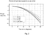
- a numerical efficiency optimization algorithm is foreseen ( Fig 4B ), based on the influence of the misalignment in the power curve of the wind turbine ( Fig 2 ) and that includes a filtering stage where the highs are attenuated and the low frequencies of the components.
- This kind of algorithms can be implemented in any current conventional wind turbine.
- optimization algorithm of numerical analysis enable a search for an optimal condition (alignment angle ⁇ *) without any previuos knowledge of the farm, and require input information of the cost function to optimize.
- This optimization algorithm of numerical analysis should have a filtering stage of low and high frequencies of wind turbine component and could be an algorithm of the following type:
- Another object of the invention is a control system capable of anticipating any possible failure in the measuring sensors, thus the control systems conducts redundant readings of the wind direction.
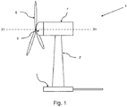
- FIG. 1 is a side view illustrating a wind turbine (1) according to one preferential embodiment of the invention.
- the wind turbine (1) includes a tower (2) that stands vertically on a foundation (3), a nacelle (4) mounted on the top part of the tower (2), and a rotor (5) mounted on the front end of the nacelle (4) for rotational support with respect of a substantially horizontal axis X1-X1.
- the rotor (5) has at least one blade (6), as shown in Figure 1 , mounted in a radial pattern with respect of its rotational axis.
- An anemometer (7) measures the wind speed in the immediate area, and an anemoscope (7) measures the wind direction, for which appropriate spots are available on the edge of the outer surface (on the top, for instance) of the wind turbine nacelle (4).
- the wind flow passing through the rotor (5) acquires a rotational moment in the direction opposite to the rotation of the rotor (5).
- the wind current measured by the anemoscope (7) which is placed in the nacelle is deviated from its original counter-current direction of the wind turbine. This effect depends on the profile of the blade root, the shape of the nacelle and the positioning of the sensor in the nacelle (4). This phenomenon can be seen in figure 3a .
- Wind turbine misalignment is construed as the condition in which the wind turbine nacelle deviates at an angle ( ⁇ ) from the real wind direction ( ⁇ ) at specific moments.
- This deviation ( ⁇ ) of the nacelle (4) with respect to the wind direction ( ⁇ ) could be surmised from different reasons; when attaining a generated power curve less than the estimated value for optimum operating conditions, by comparing the real position ( ⁇ ) of the nacelle (4) and the position that it should have based on the real direction data ( ⁇ ) of the wind obtained from the anemoscope (7), or visually when observing an alignment differing from the surrounding wind turbines.
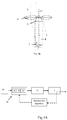
- Figure 3a depicts a wind turbine whose nacelle has a deviation ( ⁇ ) with respect to the wind direction ( ⁇ ), in which the wind does not strike the blades at a correct incidence and thus reducing power production
- figure 3b depicts a wind turbine correctly yawed with respect to the wind direction ( ⁇ ).
- the sensor is misaligned with respect to the wind incident on the rotor, but the reference sent to the alignment logic includes a °correction and therefore the nacelle is correctly aligned.
- the control system of the invention makes the nacelle oscillate by making periodic movements in the yaw of the nacelle (4) with respect to the wind direction, at a constant rate in which there are no influences of variations weather such as bursts, turbulence or changes of cuts among others.
- the oscillations have frequency ranges preferably lower than any mode of operation of the machine, therefore lower than 0.1 Hz and preferably higher than any variation of the meteorological type, therefore higher than 0.0005 Hz.
- the nacelle is oscillated, there should also be no interference from the operation of the machine such as tower resonance, rotor rotation or other vibration modes.
- the power variation data is extracted with known modulation and filtering techniques, which is combined with a numerical algorithm of power optimization ( Figure 4B ) that is based on obtaining the optimum value of an efficiency function f obtained of the aerodynamic power model of each wind turbine (1) and that must carry a filtering stage attenuating low and high frequencies of the components of the wind turbine.
- Fig. 4B forces sinusoidal oscillations of low frequency and high amplitude in the nacelle. These oscillations must be invisible from the rest of the wind turbine control to prevent the yaw control from trying to counteract them.
- f ( ⁇ ) the efficiency
- k the gain of the algorithm
- h the characteristic parameter of the filter
- s the variable of Laplace
- a and w the amplitude and the frequency respectively
- ⁇ * is the optimal value of alignment of the nacelle that maximizes the f ( ⁇ ) , so f ( ⁇ * ) will be f *.
- k / s is the filter that attenuates low frequencies and s / s + h the filter that attenuates high frequencies.
- the value ⁇ * is the one corresponding to the maximum power measured in the forced oscillation of the nacelle caused by the algorithm.
- the objective is to find an optimal value ⁇ * that maximizes the efficiency function f *.
- optimization algorithm assures stability and convergence of the result.
- the type of this optimization algorithm of numerical analysis could be: ESC (Extremum Seeking Control), the H00 (Hierarchical Optimistic Optimization) algorithm, based on yaw sweeps, or the Modified Secant algorithm, based on the Brent method.
- This function of efficiency y f( ⁇ ) is the ratio between the power measured by the wind turbine sensors and the power available in the wind.
- the yawing of the nacelle (4) moves progressively toward the positions that maximize this efficiency function, until reaching the maximum f *, and remains stable at a preset deviation value.
- the optimization algorithm is implemented in a modular composition, in such a way that it does not affect the controller.
- Figure 4A shows how the algorithm is integrated into the existing software in the wind turbine.
- the algorithm is compatible with the normal operation of the wind turbine, including maintenance actions, alarms among others.
- the misalignment signal of the wind direction sensor is sent to the alignment logic unit that subsequently orients the wind turbine nacelle.
- the output signal of the optimization algorithm is also sent to the alignment logic unit to calculate the error and the modulation signal
- the control system (20) of the invention comprises a parameters acquisition unit (8) that relates the wind direction ( ⁇ ) with the deviation ( ⁇ ) of the wind turbine nacelle (4), a wind turbine efficiency function calculation unit (9) of the efficiency function of the wind turbine (1) and a deviation comparison unit (10) of the nacelle (4) and, through a power optimization algorithm that progressively yaws the wind turbine nacelle (4) to positions that would maximize the efficiency function.
- control system (20) follows the steps below:
Landscapes
- Engineering & Computer Science (AREA)
- Life Sciences & Earth Sciences (AREA)
- Sustainable Development (AREA)
- Sustainable Energy (AREA)
- Chemical & Material Sciences (AREA)
- Combustion & Propulsion (AREA)
- Mechanical Engineering (AREA)
- General Engineering & Computer Science (AREA)
- Physics & Mathematics (AREA)
- General Physics & Mathematics (AREA)
- Automation & Control Theory (AREA)
- Wind Motors (AREA)
Abstract
Description
- The present invention refers to a device and a control system method to prevent wind turbine misalignment situations, employing mathematical algorithms implemented in the wind turbine controller based on operational variables to minimize a wind turbine's losses in annual energy production (AEP).
- A horizontal axis wind turbine consists of a stationary tower that elevates a nacelle bearing an electrical generator attached to a rotor mechanically. The rotor comprises a hub that attaches at least one blade, which transforms the wind's kinetic energy in the rotating rotor.
- It is known in the state of the art that the optimum operating point of a horizontal axis wind turbine is achieved when the rotor shaft is parallel to the direction of the wind, since this maximizes the energy produced while minimizing loads. However, the optimum production and the maximum perpendicularity to the wind do not coincide in general, due to any wind condition that generates speed asymmetries in the rotor plane. This is wind dependent and different in each wind turbine.
- The nacelle is capable of moving on its supporting tower to enable the rotor to position itself (yawing) in the direction of the wind through a mechanical system that moves it to the desired orientation (yaw system) with a view to best harnessing the wind and producing the most power. This yaw system turns the wind turbine nacelle around a vertical yaw axis, which coincides with the vertical axis of the tower until the rotational axis of the blades are parallel with the wind direction. When this optimum position is not reached, the wind turbine has a yaw error determined by the angle of deviation with respect to said optimal position.
- However, given the natural variability of the wind direction, there is a need for systems that constantly detect the wind direction and consequently adjust the position of the wind turbine so as to best harness the wind to produce maximum power. However, extreme misalignment with respect to the wind direction also causes an increase in loads on wind turbine components, resulting in the deterioration thereof.
- In this regard, the yaw system has a wind direction measuring system comprising sensors, usually installed at the top of the wind turbine nacelle behind the rotor.
- Nonetheless, in wind direction measurement there are various factors to consider that could cause retrieval of a flawed measurement value, namely the rotor's influence on the descending air currents, faulty operation of the sensors because of erroneous installation and/or configuration, ascending airflow due to the location of each wind turbine and, lastly, developments in internal blade section designs, which have evolved toward greater aerodynamic effectiveness and produce greater airflow deflection. The foregoing causes the wind turbine not to operate in the desired conditions.
-
US2015086357A1 describes a method for adjusting yaw bias in wind turbine defining an operational condition for the wind turbine during operation of the wind turbine. This method is hardly automatable, requiring subsequent manual procedures. - There are solutions in the state of the art that address misalignment issues by positioning the sensors in front of the wind turbine rotor, e.g., patent
EP2626549A1 . - Patent
US2013114067A1 describes an optical control system for a wind turbine comprising the incorporation of some sensors at the front of the wind turbine rotor that provides some measurements that, in combination with the data obtained in the wind turbine nacelle sensors, enable the positioning of the wind turbine in the optimum position. - Known state of the art includes other solutions such as patent
EP2267301B1 , which describes a wind turbine yaw control system that incorporates a wind channel that runs through the wind turbine hub and comprises an air flow measuring device to determine the yaw error through a control system. However, this solution cannot be applied to wind turbines that are already installed. - The existing solutions in the state of the art are based on the same idea: to measure the wind in the rotor and its comparison with the measurement of the sensor in the nacelle. This requires the use of additional sensors to those existing in a wind turbine (speed measurement sensors, wind direction measurement, power measurement and rotor rotation measurement) with the cost involved, in addition to the installation, removal and calibration of each measuring device of each wind turbine that needs to be adjusted.
- In light of the drawbacks of the aforementioned solutions, a need is thus envisioned for implementing a solution that could, by employing the means already existing on the wind turbines, guarantee a correct yaw error measurement to be able to position the nacelle wind turbine at the optimum operating position to assure the efficiency. The characteristics of the optimization algorithm allow the complete automation of the process, which is a technical advantage over many manual procedures of the state of the art.
- The object of the present invention is to overcome the inconveniences of the state of the art by using only basic variables such as power, wind speed, wind direction or speed of rotation of the motor for the correct measurement of the yaw misalignment by means of a systematic error control system in the alignment of the nacelle wind turbine with respect to the wind direction that optimizes the production, being general and automatic, so that it can be applied to any type of horizontal axis wind turbine installed in any location of a wind farm and that it does not imply adding additional measuring devices to those already in place (sensors for measuring wind speed and direction, power and rotor rotation). The objective of the invention is to detect the systematic misalignment of the existing orientation device with respect to positions that would maximize the efficiency function
- Therefore, the present invention entails, an automation of the alignment method without the need of additional sensors to the conventionally existing in the horizontal axis wind turbines, a numerical method that directs the search of the optimal result drastically reducing the time necessary to obtain stable results, and a low frequency filtering procedure and automatic convergence statistical criterion.
- From the State of the Art, it is known that the loss in power generated wind turbines caused by a yaw error follows a curve based on the cos2 law (see
figure 2 ), and power losses can be estimated on the basis of the different misalignment angles. - In this regard, an object of the invention is that the control system determines the need to measure the yaw angle and quantifies the misalignment value through not only direct measurement of the wind direction but also a set of values depending on the wind speed.
- The invention also mitigates the effects of the misalignment through corrective measures that apply the values obtained in the measurements, in either the PLC or data acquisition hardware.
- For this the nacelle is oscillated at a constant rate in which there are no influences of meteorological variations (bursts, turbulence, shear changes, diurnal and seasonal oscillations) or variations of the wind turbine (tower resonance, rotation of the rotor or vibration modes). These oscillations have frequency ranges lower than any mode of operation of the wind turbine and higher than any variation of weather type.
- Additionally, an algorithm of numerical analysis is associated between efficiency optimization algorithms that has as objective to find a function y = f (θ) that maximizes the efficiency of the wind turbine where θ * is the optimal alignment, the solution at each moment is proportional to the change or derivative of the analyzed function f and that incorporates a filtering stage to attenuate low frequencies of the components that generate the wind and meteorological characteristics and high frequencies of the components of the wind turbine.
- The object of the invention lies in the association of the numerical analysis method with the variations in efficiency caused by the nacelle oscillations. Efficiency being the power produced at each instant with respect to the wind.
- For this, the implementation of a numerical efficiency optimization algorithm is foreseen (
Fig 4B ), based on the influence of the misalignment in the power curve of the wind turbine (Fig 2 ) and that includes a filtering stage where the highs are attenuated and the low frequencies of the components. This kind of algorithms can be implemented in any current conventional wind turbine. - The advantages of the control system with respect to the existing in the state of the art are:
- the optimization algorithm allows the complete automation of the procedure
- does not need additional sensors to those existing in the wind turbine (wind measurement sensor, wind speed measurement sensor, rotor speed sensor and power measurement sensor)
- Use of basic variables such as power, wind speed, rotor rotation speed
- minimum convergence times of the algorithm and low uncertainty of the results.
- These optimization algorithms of numerical analysis enable a search for an optimal condition (alignment angle θ*) without any previuos knowledge of the farm, and require input information of the cost function to optimize. This optimization algorithm of numerical analysis should have a filtering stage of low and high frequencies of wind turbine component and could be an algorithm of the following type:
- ESC algorithm: Extremum-Seeking Control (IEEE control systems. 26(1):70 - 79.).
- H00 algorithm: Hierarchical Optimistic Optimization (Bubeck, S et al. "Online Optimization in x-armed bandits". OPT 2008 Optimization for Machine Learning. https://opt 2008.kyb.tuebingen.mpg.de/papers/bubeck.pdf based on yaw sweeps.
- Modified Secant algorithm, based on the Brent method (International Conference on Mechatronics & Automation, 2005, pages 248-253)
- Another object of the invention is a control system capable of anticipating any possible failure in the measuring sensors, thus the control systems conducts redundant readings of the wind direction.
- These and other aspects of the invention will be described in more detail with the help of the drawings shown below.
- The invention and its mode of operation can be understood more comprehensively from the following detailed description together with the following schematic figures:
-
Figure 1 shows a perspective view of a conventional wind turbine. -
Figure 2 depicts a curve of the existing relationship between the generated power and the yaw angle of the wind turbine according to the State of the Art. -
Figures 3a and3b respectively depict plant views of a wind turbine whose nacelle deviates from the wind direction and a wind turbine whose nacelle is aligned with the wind direction. -
Figure 4A shows a diagram of the control system implemented in the wind turbine according to the invention. -
Figure 4B shows a diagram of the algorithm implemented in the control system. -
Figure 5 shows a diagram of the operating flow of the control system. -
Figure 1 is a side view illustrating a wind turbine (1) according to one preferential embodiment of the invention. The wind turbine (1) includes a tower (2) that stands vertically on a foundation (3), a nacelle (4) mounted on the top part of the tower (2), and a rotor (5) mounted on the front end of the nacelle (4) for rotational support with respect of a substantially horizontal axis X1-X1. - The rotor (5) has at least one blade (6), as shown in
Figure 1 , mounted in a radial pattern with respect of its rotational axis. Thus, the energy from the wind when blowing against the wind turbine blades (6) from the direction of the rotational axis of the rotor (5) is converted into kinetic energy that rotates the rotor (5) on the rotational axis. An anemometer (7) measures the wind speed in the immediate area, and an anemoscope (7) measures the wind direction, for which appropriate spots are available on the edge of the outer surface (on the top, for instance) of the wind turbine nacelle (4). - The wind flow passing through the rotor (5) acquires a rotational moment in the direction opposite to the rotation of the rotor (5). The wind current measured by the anemoscope (7) which is placed in the nacelle is deviated from its original counter-current direction of the wind turbine. This effect depends on the profile of the blade root, the shape of the nacelle and the positioning of the sensor in the nacelle (4). This phenomenon can be seen in
figure 3a . - Wind turbine misalignment is construed as the condition in which the wind turbine nacelle deviates at an angle (α) from the real wind direction (γ) at specific moments. Refer to
figure 3a . This deviation (α) of the nacelle (4) with respect to the wind direction (γ) could be surmised from different reasons; when attaining a generated power curve less than the estimated value for optimum operating conditions, by comparing the real position (α) of the nacelle (4) and the position that it should have based on the real direction data (γ) of the wind obtained from the anemoscope (7), or visually when observing an alignment differing from the surrounding wind turbines. -
Figure 3a depicts a wind turbine whose nacelle has a deviation (α) with respect to the wind direction (γ), in which the wind does not strike the blades at a correct incidence and thus reducing power production, whilefigure 3b depicts a wind turbine correctly yawed with respect to the wind direction (γ). InFigure 3b , the sensor is misaligned with respect to the wind incident on the rotor, but the reference sent to the alignment logic includes a °correction and therefore the nacelle is correctly aligned. - On the other hand, from the State of the Art, it is known that the loss in power generated wind turbines caused by a yaw error follows a curve based on the cos2 law (see
figure 2 ), and power losses can be estimated on the basis of the different misalignment angles(αi). - In this regard, it is imperative to ascertain the real value of the deviation of the nacelle (4) of the wind turbine (1) with respect of the wind direction (γ) so that it can be corrected. However, it is known that noise, turbulences, vibrations of the nacelle (4) and other factors could affect the wind direction reading (γ) by the anemometer (7), hence it is necessary to relate the yaw angle deviation (α) with respect to another variable such as the wind speed.
- To do so, the control system of the invention (
Figure 4A ) makes the nacelle oscillate by making periodic movements in the yaw of the nacelle (4) with respect to the wind direction, at a constant rate in which there are no influences of variations weather such as bursts, turbulence or changes of cuts among others. The oscillations have frequency ranges preferably lower than any mode of operation of the machine, therefore lower than 0.1 Hz and preferably higher than any variation of the meteorological type, therefore higher than 0.0005 Hz. When the nacelle is oscillated, there should also be no interference from the operation of the machine such as tower resonance, rotor rotation or other vibration modes. The power variation data is extracted with known modulation and filtering techniques, which is combined with a numerical algorithm of power optimization (Figure 4B ) that is based on obtaining the optimum value of an efficiency function f obtained of the aerodynamic power model of each wind turbine (1) and that must carry a filtering stage attenuating low and high frequencies of the components of the wind turbine. - The algorithm shown in
Fig. 4B forces sinusoidal oscillations of low frequency and high amplitude in the nacelle. These oscillations must be invisible from the rest of the wind turbine control to prevent the yaw control from trying to counteract them. Being f (θ) the efficiency, k the gain of the algorithm, h the characteristic parameter of the filter, s the variable of Laplace, a and w the amplitude and the frequency respectively, θ * is the optimal value of alignment of the nacelle that maximizes the f (θ), so f (θ *) will be f *. k / s is the filter that attenuates low frequencies and s / s + h the filter that attenuates high frequencies. - The value θ * is the one corresponding to the maximum power measured in the forced oscillation of the nacelle caused by the algorithm.
- The objective is to find an optimal value θ * that maximizes the efficiency function f *.
- Optimization algorithm assures stability and convergence of the result. The type of this optimization algorithm of numerical analysis could be: ESC (Extremum Seeking Control), the H00 (Hierarchical Optimistic Optimization) algorithm, based on yaw sweeps, or the Modified Secant algorithm, based on the Brent method.
- This function of efficiency y=f(θ) is the ratio between the power measured by the wind turbine sensors and the power available in the wind. The yawing of the nacelle (4) moves progressively toward the positions that maximize this efficiency function, until reaching the maximum f*, and remains stable at a preset deviation value.
- The optimization algorithm is implemented in a modular composition, in such a way that it does not affect the controller.
Figure 4A shows how the algorithm is integrated into the existing software in the wind turbine. The algorithm is compatible with the normal operation of the wind turbine, including maintenance actions, alarms among others. The misalignment signal of the wind direction sensor is sent to the alignment logic unit that subsequently orients the wind turbine nacelle. The output signal of the optimization algorithm is also sent to the alignment logic unit to calculate the error and the modulation signal - The control system (20) of the invention, as depicted in
figure 4 , comprises a parameters acquisition unit (8) that relates the wind direction (γ) with the deviation (α) of the wind turbine nacelle (4), a wind turbine efficiency function calculation unit (9) of the efficiency function of the wind turbine (1) and a deviation comparison unit (10) of the nacelle (4) and, through a power optimization algorithm that progressively yaws the wind turbine nacelle (4) to positions that would maximize the efficiency function. - As shown in the flow diagram of the
figure 5 , the control system (20) follows the steps below: - Retrieval by existing wind turbine hardware (21) of values from different parameters, which could be wind direction, wind speed, nacelle position, produced power, twist limit condition of the wiring between tower and nacelle, yawing condition of the nacelle, and/or the wind turbine operating modes, namely emergency, stop, pause and production
- Checking the wind turbine operating mode, verifying the energy production in normal operation, i.e., in production mode, within preset wind speed ranges and without detecting alarms.
- a) If the operating mode is unsuitable, the check will be conducted again until the wind turbine is in the production mode.
- b) If the operating mode is suitable, there will be a check that the yawing and/or twist limit conditions are activated.
- If the yawing and/or twist limit conditions are activated, the calculated yaw oscillations of the efficiency function are inhibited.
- If the yawing and/or twist limit conditions are deactivated, a power optimization algorithm (
Figure 4 B) is launched and a signal known as the external deviation is obtained from this algorithm. - The optimization algorithm (
Fig 4 B) follows the steps below: - a. Adaptation of the integrity of the input variables, filtering to check that they fall within the limits; where the limits of these parameters are determined on the basis of the particular characteristics of the wind turbine (1).
- b. Determining an efficiency function y=f(θ) by calculating the ratio between the generated power obtained by the corresponding sensors and the theoretically producible power, which is determined based on the multiplication of a configurable parameter based on constants specific to each wind turbine (1), including the rotor diameter and coefficients for maximum power and wind speed. Said parameter is the product of the air density (kg/m3), the rotor surface (m2) and the coefficient for maximum power (Cpmax) (atmospheric conditions: parameter_=0.5·1.225·π·(diameter/2)2·Cpmax).
- c. Filtering of the efficiency function obtained in the previous step (s/s+h)..
- d. Demodulation of the signal obtained in the previous step, multiplying it by the actual value of the yaw oscillation signal (sin wt), obtaing ξ.
- e. Filtering the signal obtained by k/s and determining a signal known as the gradient θ̂.
- f. Accumulation of all the values obtained from the gradient signal since the beginning of calculations and integration thereof, thus attaining a signal known as external deviation θ.
- 2. Sending the external deviation θ signal to the yaw control system (11).
- 3. Comparison between the calculated external deviation value and the deviation value (α) determined by the wind sensors (7).
- If the obtained value exceeds some preset values depending on the particular characteristics of the wind turbine (1), the yaw system will move the nacelle (4) following the reference accumulating the sum of the yawing and external deviation.
- If the obtained value does not exceed the preset values, the control system (20) will impose an oscillatory movement onto the yaw system in addition to the movement of the previous step, so long as the wind conditions are within the preset safety limits.
- The sum of the described yaw movements, together with the variations of the wind per se will determine a new operating and working mode of the wind turbine (1), which will be recorded by the hardware (21) thereof, and a new cycle will begin with these data.
- While this invention has been described entirely in connection with preferential embodiments, modifications may clearly be made within its scope, which is not restricted by the aforementioned embodiments, but rather by the content of the following claims.
Claims (14)
- Control system for preventing misalignment situations of a horizontal axis wind turbine (1) equipped with a
yaw system for the nacelle (4) for yawing with respect to the wind direction comprising an acquisition unit (8) that retrieves values of parameters that relate the wind direction (γ) with a real deviation (α) of the wind turbine nacelle (4) by using the hardware already existing in the wind turbine (1), a calculation unit (9) of an efficiency function y=f(θ) of the wind turbine and a comparison unit (10) for the deviation of the nacelle (4) characterized in that, being general
automatic,
installed in any location and
requiring no extra measuring devices in addition to the ones already existing therein, (speed measurement sensors, wind direction measurement, power measurement and rotor rotation measurement),
said control system is characterized in that can detect and prevent misalignment situations of the nacelles in wind turbine implementing an optimization algorithm of numerical analysis of the efficiency function y=f(θ) that maximizes the wind turbine efficiency, where θ * is the optimal alignment, that incorporates a filtering stage to attenuate low frequencies (k/s) of the components that generate the wind and meteorological characteristics and high frequencies (s/s+h) of the components of the wind turbine and characterized in that through said algorithm, commands are generated to permit the yaw system to orient the nacelle (4) of the wind turbine (1) toward positions that would maximize the efficiency function. - Control system according to claim 1 characterized in that the calculation unit (9) calculates the efficiency function through a ratio between an obtained generated power and a theoretically producible power including rotor diameter, and maximum power and wind speed coefficients.
- Control system according to claim 2, characterized in that the theoretical power is calculated by multiplying a configurable parameter, which depends on the constants inherent to each wind turbine (1), including the rotor diameter and maximum power and wind speed coefficients, being said configurable parameter the product of the air density, the rotor surface and the coefficient for maximum power (Cpmax).
- Control system according to claim 1, characterized in that the comparison unit (10) of nacelle (4) deviation calculates the difference between the deviation value calculated by the optimization algorithm θ̂ and the deviation value (α) determined by at least one wind sensor (7). When this value exceeds configured values (between 5 ° and 10°), the yaw system will move the nacelle following the reference that has accumulated the sum of the yawing and external deviation.
- Control system for detecting and preventing wind turbine misalignment situations, characterized in that, employing the control layout in claim 1, it carries out the following stages:- retrieval by hardware (21) existing in the wind turbine (1) of parameters values, which are selected in parameters of wind direction, wind speed, nacelle position, produced power, twist limit condition of the wiring between tower and nacelle, yawing condition of the nacelle, and/or the wind turbine operating modes- checking the wind turbine (1) operating mode in normal production operation- checking the activation of the yawing and/or twist limit conditions of the nacelle (4)- launch of a power optimization algorithm- attaining the real deviation of the nacelle (4) with respect of the wind direction- comparison of the real deviation value calculated with preset deviation values based on the particular wind turbine characteristics (1)- yawing of the nacelle (4) toward a position that would maximize the efficiency function.
- Control system according to claim 5, characterized in that the stage checking the status of the wind turbine (1) is iterative until the result is normal energy production operation of the wind turbine (1) defined on the basis of the preset values according to the particular characteristics of the wind turbine (1): in production, within the preset wind value ranges and without detecting alarms
- Control method according to claim 5, characterized in that the checking stage is iterative until the yawing and/or twist limit functions of the nacelle (4) have been verified.
- Control method according to claim 5, characterized in that if the yawing and/or twist limit functions of the nacelle (4) are activated, the control system (20) prevents oscillations of the nacelle (4) for calculating the efficiency function f(θ).
- Control method according claim 1, characterized in that the power optimization algorithm incorporates a filtering stage to attenuate low and high frequencies of components of the wind turbine.
- Control method according to claim 5, characterized in that the power optimization algorithm based on attaining the optimal value of an efficiency function f(θ*) obtained from the aerodynamic power model for each wind turbine comprises the following stages:- checking and adapting by low-pass filtering of the integrity of the parameters obtained from the hardware (21) of the wind turbine (1) with respect to some preset ranges based on its particular characteristics.- determining the efficiency function of the wind turbine (1) by calculating the ratio between the obtained generated power and the theoretically producible power calculated on the basis of the particular characteristics of the wind turbine (1).- high-pass filtering of the efficiency function and demodulation of the obtained signal- determining the gradient signal by multiplying the signal obtained from the previous step by the actual deviation value of the nacelle (4) and low-pass filtering the resulting signal- accumulation of the value of the gradient signal in a variable that integrates the previous steps to secure a stabilized deviation value with respect of a preset value- attaining the real deviation of the nacelle (4) with respect of the wind direction.
- Control method according to any of the claims 5 and 9, characterized in that the power optimization algorithm is ESC (Extremum Seeking Control).
- Control method according to any of the claims 5 and 9, characterized in that the power optimization algorithm is H00 (Hierarchical Optimistic Optimization) based on yaw sweeps.
- Control method according to any of the claims 5 and 9, characterized in that the power optimization algorithm is Modified Secant based on the Brent methods.
- Control method according to claim 5, characterized in that in the stage for comparing the real deviation value determined with some preset deviation values depending on the particular characteristics of the wind turbine (1), whenever this value does not exceed the preset values, the control system (20) will activate the oscillation system of the nacelle (4).
Applications Claiming Priority (3)
| Application Number | Priority Date | Filing Date | Title |
|---|---|---|---|
| ES201500494A ES2600861B1 (en) | 2015-07-03 | 2015-07-03 | Control system to detect and avoid misalignment situations in wind turbines |
| EP15003253.0A EP3112675A1 (en) | 2015-07-03 | 2015-11-16 | Control layout and method for detecting and preventing wind turbine misalignment situations |
| PCT/ES2016/000073 WO2017005945A1 (en) | 2015-07-03 | 2016-07-01 | Correction of systematic errors in the alignment of wind turbines |
Publications (3)
| Publication Number | Publication Date |
|---|---|
| EP3321504A1 true EP3321504A1 (en) | 2018-05-16 |
| EP3321504A4 EP3321504A4 (en) | 2019-05-01 |
| EP3321504B1 EP3321504B1 (en) | 2021-03-10 |
Family
ID=55027200
Family Applications (2)
| Application Number | Title | Priority Date | Filing Date |
|---|---|---|---|
| EP15003253.0A Withdrawn EP3112675A1 (en) | 2015-07-03 | 2015-11-16 | Control layout and method for detecting and preventing wind turbine misalignment situations |
| EP16820883.3A Active EP3321504B1 (en) | 2015-07-03 | 2016-07-01 | Correction of systematic errors in the alignment of wind turbines |
Family Applications Before (1)
| Application Number | Title | Priority Date | Filing Date |
|---|---|---|---|
| EP15003253.0A Withdrawn EP3112675A1 (en) | 2015-07-03 | 2015-11-16 | Control layout and method for detecting and preventing wind turbine misalignment situations |
Country Status (7)
| Country | Link |
|---|---|
| US (1) | US10527024B2 (en) |
| EP (2) | EP3112675A1 (en) |
| CN (1) | CN107709763B (en) |
| BR (1) | BR112018000096B1 (en) |
| ES (1) | ES2600861B1 (en) |
| MX (1) | MX380382B (en) |
| WO (1) | WO2017005945A1 (en) |
Families Citing this family (14)
| Publication number | Priority date | Publication date | Assignee | Title |
|---|---|---|---|---|
| EP3187726B1 (en) | 2015-12-28 | 2018-02-28 | Acciona Windpower S.a. | Wind turbine control method and associated wind turbine |
| US11391263B2 (en) | 2017-05-31 | 2022-07-19 | Vestas Wind Systems A/S | Wind turbine yaw control system with improved wind direction tracking |
| WO2019001668A1 (en) * | 2017-06-30 | 2019-01-03 | Vestas Wind Systems A/S | Protection of a brake in a wind turbine |
| CN107742173B (en) * | 2017-11-22 | 2021-02-02 | 北京电子工程总体研究所 | Longitudinal layout method for horizontal axis wind turbine group |
| CN110318947B (en) | 2018-03-30 | 2020-06-09 | 北京金风科创风电设备有限公司 | Yaw control method, device and system for wind turbine |
| CN108843497B (en) * | 2018-06-29 | 2019-08-02 | 北京金风科创风电设备有限公司 | Yaw control method and equipment of wind generating set |
| ES2976514T3 (en) | 2018-09-17 | 2024-08-02 | American Superconductor Corp | Yaw auto-calibration for a wind turbine generator |
| CN110017247B (en) * | 2019-04-25 | 2020-05-19 | 天津瑞源电气有限公司 | Yaw wind alignment method based on self-power consumption |
| CN116157598A (en) | 2020-07-13 | 2023-05-23 | 文德斯科有限公司 | Method and system for advanced yaw control of wind turbines |
| US11231012B1 (en) * | 2020-09-22 | 2022-01-25 | General Electric Renovables Espana, S.L. | Systems and methods for controlling a wind turbine |
| CN114880889B (en) * | 2022-07-11 | 2022-09-23 | 浙江科维节能技术股份有限公司 | Efficient energy-saving design method for fan system |
| CN115559862B (en) * | 2022-08-24 | 2025-08-01 | 华能(浙江)能源开发有限公司清洁能源分公司 | Offshore wind power monitoring method and system |
| CN119696017A (en) * | 2024-11-12 | 2025-03-25 | 深圳海汇科技有限公司 | A method for automatically switching between microgrid and mains power on and off grid |
| CN120120182B (en) * | 2025-02-25 | 2025-12-30 | 内蒙古电力(集团)有限责任公司内蒙古电力科学研究院分公司 | Wind power intelligent protection control system and method based on artificial intelligence |
Family Cites Families (20)
| Publication number | Priority date | Publication date | Assignee | Title |
|---|---|---|---|---|
| DE102004051843B4 (en) * | 2004-10-25 | 2006-09-28 | Repower Systems Ag | Wind turbine and method for automatically correcting wind vane misadjustments |
| JP5022102B2 (en) * | 2007-05-25 | 2012-09-12 | 三菱重工業株式会社 | Wind power generator, wind power generator system, and power generation control method for wind power generator |
| US20100054941A1 (en) * | 2008-08-27 | 2010-03-04 | Till Hoffmann | Wind tracking system of a wind turbine |
| JP4995209B2 (en) * | 2009-01-05 | 2012-08-08 | 三菱重工業株式会社 | Wind power generator and wind direction estimating method for wind power generator |
| JP5360752B2 (en) * | 2009-01-15 | 2013-12-04 | 学校法人福岡大学 | Downwind generator |
| EP2213873A1 (en) * | 2009-01-30 | 2010-08-04 | Siemens Aktiengesellschaft | Estimating an effective wind direction for a wind turbine by means of a learning system |
| DE102009015167A1 (en) * | 2009-03-26 | 2010-09-30 | Wilkens, Bodo, Dr. | Method for tracking rotor level of wind turbine against wind direction, involves adjusting rotor level in azimuthal direction according to amount of correction value in adjustment direction that coincides with another adjustment direction |
| DK2267301T3 (en) | 2009-06-24 | 2012-11-26 | Siemens Ag | Device and method for controlling the bending of a wind turbine |
| WO2011096928A1 (en) | 2010-02-05 | 2011-08-11 | Catch the Wind, Inc. | High-density wind velocity data collection for wind turbine |
| US8202049B2 (en) * | 2010-08-31 | 2012-06-19 | Catch the Wind, Inc. | Independent blade pitch control |
| WO2012109616A2 (en) * | 2011-02-11 | 2012-08-16 | Xzeres Corp. | System and method for controlling a wind turbine including controlling yaw or other parameters |
| ES2398020B1 (en) * | 2011-03-17 | 2014-09-05 | Gamesa Innovation & Technology, S.L. | METHODS AND SYSTEMS TO RELIEF THE LOADS PRODUCED IN AEROGENERATORS BY THE WIND ASYMETRIES. |
| EP2712402B1 (en) * | 2011-05-06 | 2020-12-23 | Seawind Ocean Technology Holding BV | Systems for minimizing the yaw torque needed to control power output by yawing , for wind turbines with two hinged teetering blades. |
| CN102213182B (en) * | 2011-05-12 | 2013-09-04 | 北京金风科创风电设备有限公司 | Method for obtaining yaw error angle, yaw control method/device and wind generating set |
| DK177292B1 (en) * | 2011-06-30 | 2012-10-08 | Envision Energy Denmark Aps | A wind turbine and an associated yaw control method |
| EP2626549A1 (en) | 2012-02-08 | 2013-08-14 | ROMO Wind AG | Apparatus for adjusting the yaw of a wind turbine |
| US9512820B2 (en) * | 2013-02-19 | 2016-12-06 | Siemens Aktiengesellschaft | Method and system for improving wind farm power production efficiency |
| US20150086357A1 (en) | 2013-09-24 | 2015-03-26 | General Electric Company | Wind turbine and method for adjusting yaw bias in wind turbine |
| CN104314757B (en) * | 2014-10-15 | 2017-03-29 | 国电联合动力技术有限公司 | A kind of wind generating set yaw control method and system |
| EP3096004A1 (en) * | 2015-05-18 | 2016-11-23 | ABB Technology AG | Wind farm inertial response |
-
2015
- 2015-07-03 ES ES201500494A patent/ES2600861B1/en not_active Expired - Fee Related
- 2015-11-16 EP EP15003253.0A patent/EP3112675A1/en not_active Withdrawn
-
2016
- 2016-07-01 US US15/741,418 patent/US10527024B2/en active Active
- 2016-07-01 BR BR112018000096-5A patent/BR112018000096B1/en active IP Right Grant
- 2016-07-01 CN CN201680039456.6A patent/CN107709763B/en active Active
- 2016-07-01 EP EP16820883.3A patent/EP3321504B1/en active Active
- 2016-07-01 WO PCT/ES2016/000073 patent/WO2017005945A1/en not_active Ceased
- 2016-07-01 MX MX2018000083A patent/MX380382B/en unknown
Also Published As
| Publication number | Publication date |
|---|---|
| CN107709763B (en) | 2021-03-23 |
| US20180372070A1 (en) | 2018-12-27 |
| US10527024B2 (en) | 2020-01-07 |
| ES2600861B1 (en) | 2017-11-21 |
| BR112018000096B1 (en) | 2023-01-10 |
| MX2018000083A (en) | 2018-03-16 |
| MX380382B (en) | 2025-03-12 |
| CN107709763A (en) | 2018-02-16 |
| EP3112675A1 (en) | 2017-01-04 |
| EP3321504A4 (en) | 2019-05-01 |
| ES2600861A1 (en) | 2017-02-13 |
| EP3321504B1 (en) | 2021-03-10 |
| BR112018000096A2 (en) | 2018-08-28 |
| WO2017005945A1 (en) | 2017-01-12 |
Similar Documents
| Publication | Publication Date | Title |
|---|---|---|
| EP3321504B1 (en) | Correction of systematic errors in the alignment of wind turbines | |
| US9562515B2 (en) | Method and apparatus for wind turbine noise reduction | |
| US9004862B2 (en) | Calibration of wind turbine sensor | |
| US10036692B2 (en) | System and method for estimating rotor blade loads of a wind turbine | |
| EP2840258A1 (en) | System and method for preventing excessive loading on a wind turbine | |
| US9341159B2 (en) | Methods for controlling wind turbine loading | |
| US9920742B2 (en) | Dynamic cut-in wind speed for wind turbines | |
| US10451036B2 (en) | Adjustment factor for aerodynamic performance map | |
| US11732696B2 (en) | Load sensors in wind turbines | |
| EP4194686A1 (en) | System and method for controlling blade pitch of wind turbine rotor blades to reduce vibrations and limit loads in a locked condition of the rotor hub | |
| US20220220935A1 (en) | Thrust control for wind turbines using active sensing of wind turbulence | |
| EP3514373A1 (en) | Twist correction factor for aerodynamic performance map used in wind turbine control | |
| TW201732150A (en) | Control device of plurality of wind turbines and control method of wind farm or plurality of wind turbines | |
| US12152565B2 (en) | Vibrations in wind turbines | |
| ES2870537T3 (en) | Correction of systematic errors in the alignment of wind turbines |
Legal Events
| Date | Code | Title | Description |
|---|---|---|---|
| STAA | Information on the status of an ep patent application or granted ep patent |
Free format text: STATUS: THE INTERNATIONAL PUBLICATION HAS BEEN MADE |
|
| PUAI | Public reference made under article 153(3) epc to a published international application that has entered the european phase |
Free format text: ORIGINAL CODE: 0009012 |
|
| STAA | Information on the status of an ep patent application or granted ep patent |
Free format text: STATUS: REQUEST FOR EXAMINATION WAS MADE |
|
| 17P | Request for examination filed |
Effective date: 20180110 |
|
| AK | Designated contracting states |
Kind code of ref document: A1 Designated state(s): AL AT BE BG CH CY CZ DE DK EE ES FI FR GB GR HR HU IE IS IT LI LT LU LV MC MK MT NL NO PL PT RO RS SE SI SK SM TR |
|
| AX | Request for extension of the european patent |
Extension state: BA ME |
|
| DAV | Request for validation of the european patent (deleted) | ||
| DAX | Request for extension of the european patent (deleted) | ||
| RAP1 | Party data changed (applicant data changed or rights of an application transferred) |
Owner name: SIEMENS GAMESA RENEWABLE ENERGY INNOVATION & TECHN |
|
| A4 | Supplementary search report drawn up and despatched |
Effective date: 20190402 |
|
| RIC1 | Information provided on ipc code assigned before grant |
Ipc: F03D 7/02 20060101AFI20190327BHEP |
|
| GRAP | Despatch of communication of intention to grant a patent |
Free format text: ORIGINAL CODE: EPIDOSNIGR1 |
|
| STAA | Information on the status of an ep patent application or granted ep patent |
Free format text: STATUS: GRANT OF PATENT IS INTENDED |
|
| INTG | Intention to grant announced |
Effective date: 20201022 |
|
| GRAS | Grant fee paid |
Free format text: ORIGINAL CODE: EPIDOSNIGR3 |
|
| GRAA | (expected) grant |
Free format text: ORIGINAL CODE: 0009210 |
|
| STAA | Information on the status of an ep patent application or granted ep patent |
Free format text: STATUS: THE PATENT HAS BEEN GRANTED |
|
| AK | Designated contracting states |
Kind code of ref document: B1 Designated state(s): AL AT BE BG CH CY CZ DE DK EE ES FI FR GB GR HR HU IE IS IT LI LT LU LV MC MK MT NL NO PL PT RO RS SE SI SK SM TR |
|
| REG | Reference to a national code |
Ref country code: GB Ref legal event code: FG4D |
|
| REG | Reference to a national code |
Ref country code: CH Ref legal event code: EP Ref country code: AT Ref legal event code: REF Ref document number: 1370070 Country of ref document: AT Kind code of ref document: T Effective date: 20210315 |
|
| REG | Reference to a national code |
Ref country code: IE Ref legal event code: FG4D |
|
| REG | Reference to a national code |
Ref country code: DE Ref legal event code: R096 Ref document number: 602016054137 Country of ref document: DE |
|
| REG | Reference to a national code |
Ref country code: DK Ref legal event code: T3 Effective date: 20210421 |
|
| REG | Reference to a national code |
Ref country code: NL Ref legal event code: FP |
|
| REG | Reference to a national code |
Ref country code: LT Ref legal event code: MG9D |
|
| PG25 | Lapsed in a contracting state [announced via postgrant information from national office to epo] |
Ref country code: BG Free format text: LAPSE BECAUSE OF FAILURE TO SUBMIT A TRANSLATION OF THE DESCRIPTION OR TO PAY THE FEE WITHIN THE PRESCRIBED TIME-LIMIT Effective date: 20210610 Ref country code: LT Free format text: LAPSE BECAUSE OF FAILURE TO SUBMIT A TRANSLATION OF THE DESCRIPTION OR TO PAY THE FEE WITHIN THE PRESCRIBED TIME-LIMIT Effective date: 20210310 Ref country code: HR Free format text: LAPSE BECAUSE OF FAILURE TO SUBMIT A TRANSLATION OF THE DESCRIPTION OR TO PAY THE FEE WITHIN THE PRESCRIBED TIME-LIMIT Effective date: 20210310 Ref country code: FI Free format text: LAPSE BECAUSE OF FAILURE TO SUBMIT A TRANSLATION OF THE DESCRIPTION OR TO PAY THE FEE WITHIN THE PRESCRIBED TIME-LIMIT Effective date: 20210310 Ref country code: GR Free format text: LAPSE BECAUSE OF FAILURE TO SUBMIT A TRANSLATION OF THE DESCRIPTION OR TO PAY THE FEE WITHIN THE PRESCRIBED TIME-LIMIT Effective date: 20210611 Ref country code: NO Free format text: LAPSE BECAUSE OF FAILURE TO SUBMIT A TRANSLATION OF THE DESCRIPTION OR TO PAY THE FEE WITHIN THE PRESCRIBED TIME-LIMIT Effective date: 20210610 |
|
| REG | Reference to a national code |
Ref country code: AT Ref legal event code: MK05 Ref document number: 1370070 Country of ref document: AT Kind code of ref document: T Effective date: 20210310 |
|
| PG25 | Lapsed in a contracting state [announced via postgrant information from national office to epo] |
Ref country code: RS Free format text: LAPSE BECAUSE OF FAILURE TO SUBMIT A TRANSLATION OF THE DESCRIPTION OR TO PAY THE FEE WITHIN THE PRESCRIBED TIME-LIMIT Effective date: 20210310 Ref country code: LV Free format text: LAPSE BECAUSE OF FAILURE TO SUBMIT A TRANSLATION OF THE DESCRIPTION OR TO PAY THE FEE WITHIN THE PRESCRIBED TIME-LIMIT Effective date: 20210310 Ref country code: SE Free format text: LAPSE BECAUSE OF FAILURE TO SUBMIT A TRANSLATION OF THE DESCRIPTION OR TO PAY THE FEE WITHIN THE PRESCRIBED TIME-LIMIT Effective date: 20210310 |
|
| REG | Reference to a national code |
Ref country code: ES Ref legal event code: FG2A Ref document number: 2870537 Country of ref document: ES Kind code of ref document: T3 Effective date: 20211027 |
|
| PG25 | Lapsed in a contracting state [announced via postgrant information from national office to epo] |
Ref country code: EE Free format text: LAPSE BECAUSE OF FAILURE TO SUBMIT A TRANSLATION OF THE DESCRIPTION OR TO PAY THE FEE WITHIN THE PRESCRIBED TIME-LIMIT Effective date: 20210310 Ref country code: CZ Free format text: LAPSE BECAUSE OF FAILURE TO SUBMIT A TRANSLATION OF THE DESCRIPTION OR TO PAY THE FEE WITHIN THE PRESCRIBED TIME-LIMIT Effective date: 20210310 Ref country code: SM Free format text: LAPSE BECAUSE OF FAILURE TO SUBMIT A TRANSLATION OF THE DESCRIPTION OR TO PAY THE FEE WITHIN THE PRESCRIBED TIME-LIMIT Effective date: 20210310 Ref country code: AT Free format text: LAPSE BECAUSE OF FAILURE TO SUBMIT A TRANSLATION OF THE DESCRIPTION OR TO PAY THE FEE WITHIN THE PRESCRIBED TIME-LIMIT Effective date: 20210310 |
|
| PG25 | Lapsed in a contracting state [announced via postgrant information from national office to epo] |
Ref country code: SK Free format text: LAPSE BECAUSE OF FAILURE TO SUBMIT A TRANSLATION OF THE DESCRIPTION OR TO PAY THE FEE WITHIN THE PRESCRIBED TIME-LIMIT Effective date: 20210310 Ref country code: RO Free format text: LAPSE BECAUSE OF FAILURE TO SUBMIT A TRANSLATION OF THE DESCRIPTION OR TO PAY THE FEE WITHIN THE PRESCRIBED TIME-LIMIT Effective date: 20210310 Ref country code: PL Free format text: LAPSE BECAUSE OF FAILURE TO SUBMIT A TRANSLATION OF THE DESCRIPTION OR TO PAY THE FEE WITHIN THE PRESCRIBED TIME-LIMIT Effective date: 20210310 Ref country code: PT Free format text: LAPSE BECAUSE OF FAILURE TO SUBMIT A TRANSLATION OF THE DESCRIPTION OR TO PAY THE FEE WITHIN THE PRESCRIBED TIME-LIMIT Effective date: 20210712 Ref country code: IS Free format text: LAPSE BECAUSE OF FAILURE TO SUBMIT A TRANSLATION OF THE DESCRIPTION OR TO PAY THE FEE WITHIN THE PRESCRIBED TIME-LIMIT Effective date: 20210710 |
|
| REG | Reference to a national code |
Ref country code: DE Ref legal event code: R097 Ref document number: 602016054137 Country of ref document: DE |
|
| PLBE | No opposition filed within time limit |
Free format text: ORIGINAL CODE: 0009261 |
|
| STAA | Information on the status of an ep patent application or granted ep patent |
Free format text: STATUS: NO OPPOSITION FILED WITHIN TIME LIMIT |
|
| PG25 | Lapsed in a contracting state [announced via postgrant information from national office to epo] |
Ref country code: AL Free format text: LAPSE BECAUSE OF FAILURE TO SUBMIT A TRANSLATION OF THE DESCRIPTION OR TO PAY THE FEE WITHIN THE PRESCRIBED TIME-LIMIT Effective date: 20210310 |
|
| 26N | No opposition filed |
Effective date: 20211213 |
|
| PG25 | Lapsed in a contracting state [announced via postgrant information from national office to epo] |
Ref country code: SI Free format text: LAPSE BECAUSE OF FAILURE TO SUBMIT A TRANSLATION OF THE DESCRIPTION OR TO PAY THE FEE WITHIN THE PRESCRIBED TIME-LIMIT Effective date: 20210310 |
|
| REG | Reference to a national code |
Ref country code: CH Ref legal event code: PL |
|
| PG25 | Lapsed in a contracting state [announced via postgrant information from national office to epo] |
Ref country code: MC Free format text: LAPSE BECAUSE OF FAILURE TO SUBMIT A TRANSLATION OF THE DESCRIPTION OR TO PAY THE FEE WITHIN THE PRESCRIBED TIME-LIMIT Effective date: 20210310 |
|
| REG | Reference to a national code |
Ref country code: BE Ref legal event code: MM Effective date: 20210731 |
|
| PG25 | Lapsed in a contracting state [announced via postgrant information from national office to epo] |
Ref country code: LI Free format text: LAPSE BECAUSE OF NON-PAYMENT OF DUE FEES Effective date: 20210731 Ref country code: IT Free format text: LAPSE BECAUSE OF FAILURE TO SUBMIT A TRANSLATION OF THE DESCRIPTION OR TO PAY THE FEE WITHIN THE PRESCRIBED TIME-LIMIT Effective date: 20210310 Ref country code: CH Free format text: LAPSE BECAUSE OF NON-PAYMENT OF DUE FEES Effective date: 20210731 |
|
| PG25 | Lapsed in a contracting state [announced via postgrant information from national office to epo] |
Ref country code: IS Free format text: LAPSE BECAUSE OF FAILURE TO SUBMIT A TRANSLATION OF THE DESCRIPTION OR TO PAY THE FEE WITHIN THE PRESCRIBED TIME-LIMIT Effective date: 20210710 Ref country code: LU Free format text: LAPSE BECAUSE OF NON-PAYMENT OF DUE FEES Effective date: 20210701 |
|
| PG25 | Lapsed in a contracting state [announced via postgrant information from national office to epo] |
Ref country code: IE Free format text: LAPSE BECAUSE OF NON-PAYMENT OF DUE FEES Effective date: 20210701 Ref country code: BE Free format text: LAPSE BECAUSE OF NON-PAYMENT OF DUE FEES Effective date: 20210731 |
|
| REG | Reference to a national code |
Ref country code: DE Ref legal event code: R082 Ref document number: 602016054137 Country of ref document: DE Representative=s name: SAUTHOFF, KARSTEN, DIPL.-ING. UNIV., DE |
|
| PG25 | Lapsed in a contracting state [announced via postgrant information from national office to epo] |
Ref country code: HU Free format text: LAPSE BECAUSE OF FAILURE TO SUBMIT A TRANSLATION OF THE DESCRIPTION OR TO PAY THE FEE WITHIN THE PRESCRIBED TIME-LIMIT; INVALID AB INITIO Effective date: 20160701 |
|
| PG25 | Lapsed in a contracting state [announced via postgrant information from national office to epo] |
Ref country code: CY Free format text: LAPSE BECAUSE OF FAILURE TO SUBMIT A TRANSLATION OF THE DESCRIPTION OR TO PAY THE FEE WITHIN THE PRESCRIBED TIME-LIMIT Effective date: 20210310 |
|
| PG25 | Lapsed in a contracting state [announced via postgrant information from national office to epo] |
Ref country code: MK Free format text: LAPSE BECAUSE OF FAILURE TO SUBMIT A TRANSLATION OF THE DESCRIPTION OR TO PAY THE FEE WITHIN THE PRESCRIBED TIME-LIMIT Effective date: 20210310 |
|
| PG25 | Lapsed in a contracting state [announced via postgrant information from national office to epo] |
Ref country code: TR Free format text: LAPSE BECAUSE OF FAILURE TO SUBMIT A TRANSLATION OF THE DESCRIPTION OR TO PAY THE FEE WITHIN THE PRESCRIBED TIME-LIMIT Effective date: 20210310 |
|
| PGFP | Annual fee paid to national office [announced via postgrant information from national office to epo] |
Ref country code: NL Payment date: 20240725 Year of fee payment: 9 |
|
| PG25 | Lapsed in a contracting state [announced via postgrant information from national office to epo] |
Ref country code: MT Free format text: LAPSE BECAUSE OF FAILURE TO SUBMIT A TRANSLATION OF THE DESCRIPTION OR TO PAY THE FEE WITHIN THE PRESCRIBED TIME-LIMIT Effective date: 20210310 |
|
| PGFP | Annual fee paid to national office [announced via postgrant information from national office to epo] |
Ref country code: ES Payment date: 20250812 Year of fee payment: 10 |
|
| PGFP | Annual fee paid to national office [announced via postgrant information from national office to epo] |
Ref country code: DE Payment date: 20250728 Year of fee payment: 10 Ref country code: DK Payment date: 20250725 Year of fee payment: 10 |
|
| PGFP | Annual fee paid to national office [announced via postgrant information from national office to epo] |
Ref country code: GB Payment date: 20250722 Year of fee payment: 10 |
|
| PGFP | Annual fee paid to national office [announced via postgrant information from national office to epo] |
Ref country code: FR Payment date: 20250725 Year of fee payment: 10 |
|
| REG | Reference to a national code |
Ref country code: NL Ref legal event code: MM Effective date: 20250801 |
|
| PG25 | Lapsed in a contracting state [announced via postgrant information from national office to epo] |
Ref country code: NL Free format text: LAPSE BECAUSE OF NON-PAYMENT OF DUE FEES Effective date: 20250801 |