EP3321491A1 - Electrically boosted regenerative bleed air system - Google Patents
Electrically boosted regenerative bleed air system Download PDFInfo
- Publication number
- EP3321491A1 EP3321491A1 EP17201611.5A EP17201611A EP3321491A1 EP 3321491 A1 EP3321491 A1 EP 3321491A1 EP 17201611 A EP17201611 A EP 17201611A EP 3321491 A1 EP3321491 A1 EP 3321491A1
- Authority
- EP
- European Patent Office
- Prior art keywords
- bleed air
- generator
- turbo
- aircraft
- compressor
- Prior art date
- Legal status (The legal status is an assumption and is not a legal conclusion. Google has not performed a legal analysis and makes no representation as to the accuracy of the status listed.)
- Granted
Links
Images



Classifications
-
- F—MECHANICAL ENGINEERING; LIGHTING; HEATING; WEAPONS; BLASTING
- F02—COMBUSTION ENGINES; HOT-GAS OR COMBUSTION-PRODUCT ENGINE PLANTS
- F02C—GAS-TURBINE PLANTS; AIR INTAKES FOR JET-PROPULSION PLANTS; CONTROLLING FUEL SUPPLY IN AIR-BREATHING JET-PROPULSION PLANTS
- F02C6/00—Plural gas-turbine plants; Combinations of gas-turbine plants with other apparatus; Adaptations of gas-turbine plants for special use
- F02C6/04—Gas-turbine plants providing heated or pressurised working fluid for other apparatus, e.g. without mechanical power output
- F02C6/06—Gas-turbine plants providing heated or pressurised working fluid for other apparatus, e.g. without mechanical power output providing compressed gas
- F02C6/08—Gas-turbine plants providing heated or pressurised working fluid for other apparatus, e.g. without mechanical power output providing compressed gas the gas being bled from the gas-turbine compressor
-
- B—PERFORMING OPERATIONS; TRANSPORTING
- B64—AIRCRAFT; AVIATION; COSMONAUTICS
- B64D—EQUIPMENT FOR FITTING IN OR TO AIRCRAFT; FLIGHT SUITS; PARACHUTES; ARRANGEMENT OR MOUNTING OF POWER PLANTS OR PROPULSION TRANSMISSIONS IN AIRCRAFT
- B64D13/00—Arrangements or adaptations of air-treatment apparatus for aircraft crew or passengers, or freight space
- B64D13/06—Arrangements or adaptations of air-treatment apparatus for aircraft crew or passengers, or freight space the air being conditioned
-
- B—PERFORMING OPERATIONS; TRANSPORTING
- B64—AIRCRAFT; AVIATION; COSMONAUTICS
- B64D—EQUIPMENT FOR FITTING IN OR TO AIRCRAFT; FLIGHT SUITS; PARACHUTES; ARRANGEMENT OR MOUNTING OF POWER PLANTS OR PROPULSION TRANSMISSIONS IN AIRCRAFT
- B64D15/00—De-icing or preventing icing on exterior surfaces of aircraft
- B64D15/02—De-icing or preventing icing on exterior surfaces of aircraft by ducted hot gas or liquid
- B64D15/04—Hot gas application
-
- F—MECHANICAL ENGINEERING; LIGHTING; HEATING; WEAPONS; BLASTING
- F02—COMBUSTION ENGINES; HOT-GAS OR COMBUSTION-PRODUCT ENGINE PLANTS
- F02C—GAS-TURBINE PLANTS; AIR INTAKES FOR JET-PROPULSION PLANTS; CONTROLLING FUEL SUPPLY IN AIR-BREATHING JET-PROPULSION PLANTS
- F02C7/00—Features, components parts, details or accessories, not provided for in, or of interest apart form groups F02C1/00 - F02C6/00; Air intakes for jet-propulsion plants
- F02C7/32—Arrangement, mounting, or driving, of auxiliaries
-
- B—PERFORMING OPERATIONS; TRANSPORTING
- B64—AIRCRAFT; AVIATION; COSMONAUTICS
- B64D—EQUIPMENT FOR FITTING IN OR TO AIRCRAFT; FLIGHT SUITS; PARACHUTES; ARRANGEMENT OR MOUNTING OF POWER PLANTS OR PROPULSION TRANSMISSIONS IN AIRCRAFT
- B64D13/00—Arrangements or adaptations of air-treatment apparatus for aircraft crew or passengers, or freight space
- B64D13/06—Arrangements or adaptations of air-treatment apparatus for aircraft crew or passengers, or freight space the air being conditioned
- B64D2013/0603—Environmental Control Systems
- B64D2013/0618—Environmental Control Systems with arrangements for reducing or managing bleed air, using another air source, e.g. ram air
-
- B—PERFORMING OPERATIONS; TRANSPORTING
- B64—AIRCRAFT; AVIATION; COSMONAUTICS
- B64D—EQUIPMENT FOR FITTING IN OR TO AIRCRAFT; FLIGHT SUITS; PARACHUTES; ARRANGEMENT OR MOUNTING OF POWER PLANTS OR PROPULSION TRANSMISSIONS IN AIRCRAFT
- B64D13/00—Arrangements or adaptations of air-treatment apparatus for aircraft crew or passengers, or freight space
- B64D13/06—Arrangements or adaptations of air-treatment apparatus for aircraft crew or passengers, or freight space the air being conditioned
- B64D2013/0603—Environmental Control Systems
- B64D2013/0648—Environmental Control Systems with energy recovery means, e.g. using turbines
-
- F—MECHANICAL ENGINEERING; LIGHTING; HEATING; WEAPONS; BLASTING
- F05—INDEXING SCHEMES RELATING TO ENGINES OR PUMPS IN VARIOUS SUBCLASSES OF CLASSES F01-F04
- F05D—INDEXING SCHEME FOR ASPECTS RELATING TO NON-POSITIVE-DISPLACEMENT MACHINES OR ENGINES, GAS-TURBINES OR JET-PROPULSION PLANTS
- F05D2220/00—Application
- F05D2220/30—Application in turbines
- F05D2220/32—Application in turbines in gas turbines
- F05D2220/323—Application in turbines in gas turbines for aircraft propulsion, e.g. jet engines
-
- F—MECHANICAL ENGINEERING; LIGHTING; HEATING; WEAPONS; BLASTING
- F05—INDEXING SCHEMES RELATING TO ENGINES OR PUMPS IN VARIOUS SUBCLASSES OF CLASSES F01-F04
- F05D—INDEXING SCHEME FOR ASPECTS RELATING TO NON-POSITIVE-DISPLACEMENT MACHINES OR ENGINES, GAS-TURBINES OR JET-PROPULSION PLANTS
- F05D2220/00—Application
- F05D2220/60—Application making use of surplus or waste energy
- F05D2220/62—Application making use of surplus or waste energy with energy recovery turbines
-
- F—MECHANICAL ENGINEERING; LIGHTING; HEATING; WEAPONS; BLASTING
- F05—INDEXING SCHEMES RELATING TO ENGINES OR PUMPS IN VARIOUS SUBCLASSES OF CLASSES F01-F04
- F05D—INDEXING SCHEME FOR ASPECTS RELATING TO NON-POSITIVE-DISPLACEMENT MACHINES OR ENGINES, GAS-TURBINES OR JET-PROPULSION PLANTS
- F05D2220/00—Application
- F05D2220/70—Application in combination with
- F05D2220/76—Application in combination with an electrical generator
-
- F—MECHANICAL ENGINEERING; LIGHTING; HEATING; WEAPONS; BLASTING
- F05—INDEXING SCHEMES RELATING TO ENGINES OR PUMPS IN VARIOUS SUBCLASSES OF CLASSES F01-F04
- F05D—INDEXING SCHEME FOR ASPECTS RELATING TO NON-POSITIVE-DISPLACEMENT MACHINES OR ENGINES, GAS-TURBINES OR JET-PROPULSION PLANTS
- F05D2270/00—Control
- F05D2270/01—Purpose of the control system
- F05D2270/06—Purpose of the control system to match engine to driven device
Definitions
- This application relates to an aircraft, and more particularly, to a bleed air system for supplying air to one or more aircraft systems including an environmental control system.
- Air supply to these systems is typically provided by bleed air extracted from or provided by a compressor of an aircraft engine.
- bleed air is often extracted from a high stage of a low-pressure compressor of the aircraft engine.
- bleed air is often extracted from an eighth stage compressor of an aircraft engine.
- the pressurized bleed air is then often cooled via a precooler and a pressure regulating valve prior to providing the bleed air to a system of the aircraft (e.g., environmental control system).
- a portion of the energy spent by the engine to produce the bleed air is wasted when cooling the bleed air via the precooler and reducing the pressure of the bleed air at the pressure regulating valve.
- This reduction in temperature and pressure dissipates the energy imparted to the bleed air by the engine without recovering it.
- This reduction in the efficiency of the bleed air system causes the engine to burn more fuel, thereby reducing the aircraft's overall fuel efficiency.
- the system additionally includes a turbo-generator having a turbine and a generator.
- the generator is driven by rotation of the turbine.
- a boost compressor is fluidly coupled to the port. Bleed air from the port is selectively provided to one of the turbo-generator and the boost compressor based on a demand of the aircraft system.
- Also disclosed herein is a method of operating a bleed air system of an aircraft including determining a demand of one or more aircraft systems, extracting bleed air from an engine via a port, providing the bleed air to a turbo-generator if an energy of the bleed air is greater than the demand of the one or more aircraft systems, and providing the bleed air to a boost compressor if the energy of the bleed air is less than the demand of the one or more aircraft systems.
- FIG. 1 illustrates an example of a commercial aircraft 10 having aircraft engines 20 that may embody aspects of the teachings of this disclosure.
- FIG. 2 an example of a gas turbine engine 20 configured for use in the aircraft 10 is illustrated schematically.
- the gas turbine engine 20 disclosed herein is a two-spool turbofan that generally incorporates a fan section 22, a compressor section 24, a combustor section 26 and a turbine section 28.
- Alternative engines might include an augmentor section (not shown) among other systems or features.
- the fan section 22 drives air along a bypass flow path while the compressor section 24 drives air along a core flow path for compression and communication into the combustor section 26 and then expansion through the turbine section 28.
- turbofan gas turbine engine 20 depicted as a turbofan gas turbine engine 20 in the disclosed non-limiting embodiment, it should be understood that the concepts described herein are not limited to use with turbofans as the teachings may be applied to other types of turbine engines, such as three-spool architectures for example.
- the engine 20 generally includes a low spool 30 and a high spool 32 mounted for rotation about an engine central longitudinal axis A relative to an engine static structure 36 via several bearing systems 38. It should be understood that various bearing systems 38 at various locations may alternatively or additionally be provided.
- the low spool 30 generally includes an inner shaft 40 that interconnects a fan 42, a low pressure compressor 44, and a low pressure turbine 46.
- the inner shaft 40 may be connected to the fan 42 directly or through a geared architecture 48 to drive the fan 42 at a different, typically lower, speed than the low spool 30.
- the high spool 32 includes an outer shaft 50 that interconnects a high pressure compressor 52 and a high pressure turbine 54.
- a combustor 56 is arranged between the high pressure compressor 52 and the high pressure turbine 54.
- the inner shaft 40 and the outer shaft 50 are concentric and rotate about the engine central longitudinal axis A which is collinear with their longitudinal axes.
- the core airflow is compressed by the low pressure compressor 44 then the high pressure compressor 52, mixed and burned with fuel in the combustor 56, then expanded over the high pressure turbine 54 and low pressure turbine 46.
- the turbines 54, 46 rotationally drive the respective low spool 30 and high spool 32 in response to the expansion.
- each engine 20 of the aircraft 10 may employ a dedicated bleed air system 60, or the plurality of engines 20 may employ a common bleed air system 60.
- the bleed air system 60 provides compressed or pressurized air to one or more aircraft systems such as, for example, an environmental control system, illustrated schematically at 58, to pressurize the cabin of an aircraft 10.
- the bleed air may be used for anti-icing or deicing, heating or cooling, and/or operating pneumatic equipment, as illustrated schematically at 59.
- the bleed air system 60 includes at least one port 62 for extracting air at various stages of the engine the engine 20.
- the system 60 includes one or more ports 62 configured to bleed low pressure air from a portion of the low pressure spool 30, such as the low pressure compressor 44 for example.
- the air drawn from the port 62 may have a maximum temperature of about 800°F and a maximum pressure of about 150 psia.
- embodiments where the port 62 is located at another low pressure position, or alternatively, is configured to draw high pressure bleed air are also contemplated herein.
- the bleed air system 60 additionally includes a turbo-generator 64 and a boost compressor 66.
- a first bleed passage 68 fluidly couples the port 62 to the turbo-generator 64
- a second bleed passage 70 fluidly couples the port 62 to the boost-compressor 66.
- the second bleed passage 70 extends from the first bleed passage 68 upstream from the turbo-generator 64.
- An isolation valve 72 may be disposed within the second passage 70 upstream from the inlet 74 of the boost compressor 66. The isolation valve 72 may be selectively operable to control a flow of bleed air to the boost-compressor 66. It should be understood that the system 60 illustrated and described herein is intended as an example only, and embodiments of the bleed system 60 where the first bleed passage 68 and the second bleed passage 70 are not arranged in fluid communication are also within the scope of the disclosure.
- the bleed air output from both the turbo-generator 64 and the boost-compressor 66 may be provided to any of a number of aircraft systems 58, 59.
- the outlet passages 76, 78 extending from the turbo-generator 64 and the boost-compressor 66, respectively, may be fluidly coupled.
- a one way check valve 80 is positioned downstream from the turbo-generator 64, but upstream from the interface between the outlet passages 76, 78. The check valve 80 is configured to prevent the flow of bleed air from the outlet of the compressor 66 from flowing through the outlet passages 76, 78 towards the turbo-generator 64.
- bleed air from the port 62 is selectively provided to one of the turbo-generator 64 and the boost compressor 66.
- the air is supplied to the turbo-generator 64.
- the turbo-generator 64 is configured to reduce the pressure and/or the temperature of the air provided thereto from the bleed port 62.
- the turbo-generator 64 is configured to reduce the temperature of the bleed air to less than 450°F and reduce the pressure of the bleed air to less than 50 psia.
- the turbo-generator 64 includes a turbine 82 that directly drives an electric generator 84.
- the turbine 82 is mounted on a shaft 86 and the electric generator 84 includes a shaft 88.
- a coupler 90 separate from or integrally formed with one of the shafts 86, 88, operably couples the turbine shaft 86 and the generator shaft 88 such that rotation of the turbine shaft 86 is transmitted to the generator shaft 88.
- Rotation of the turbine 82 driven by the flow of bleed air provided at an inlet opening 92, drives rotation of the generator shaft 88.
- rotation of the turbine 82 extracts energy from the bleed air and converts it into electrical energy via the generator 84.
- the energy created at the generator 84 may be stored, or alternatively, may be sent to an aircraft bus (not shown) where it is then supplied to one or more electrical loads of the aircraft 10.
- the operational parameters of the turbo-generator 64 may be varied to achieve a desired reduction in not only pressure, but also temperature of the bleed air. For example, if the temperature of the bleed air requires cooling, the current flow from the generator 84 may be increased causing the generator 84 to develop more input torque. The increased torque will result in slower rotation of the turbine 82 causing more energy to be extracted from the bleed air before exiting from an outlet 94 of the turbo-generator 64.
- the isolation valve 72 is opened and the bleed air is provided to the boost compressor 66.
- the boost compressor 66 includes a compressor 96 coupled to a high temperature motor 98.
- the boost compressor 66 is configured to add energy to the bleed air when needed and to increase the pressure and/or temperature of the bleed air.
- electrical energy such as supplied by the aircraft bus for example, is used to operate the motor 98 of the boost compressor 66.
- the electrical energy is converted into pneumatic energy which is then added to the low pressure bleed air within the boost compressor 66.
- the bleed air system illustrated and described herein eliminates the need for bleed air hardware including valves and a pre-cooler, thereby increasing the reliability of the bleed air system. Further, by capturing excess energy of the bleed air, the bleed air system 60 which further increases the fuel efficiency of the aircraft.
Landscapes
- Engineering & Computer Science (AREA)
- Chemical & Material Sciences (AREA)
- Combustion & Propulsion (AREA)
- Mechanical Engineering (AREA)
- General Engineering & Computer Science (AREA)
- Aviation & Aerospace Engineering (AREA)
- Health & Medical Sciences (AREA)
- General Health & Medical Sciences (AREA)
- Pulmonology (AREA)
- Structures Of Non-Positive Displacement Pumps (AREA)
- Control Of Turbines (AREA)
Abstract
Description
- This application relates to an aircraft, and more particularly, to a bleed air system for supplying air to one or more aircraft systems including an environmental control system.
- Commercial aircrafts or jetliners typically employ an environmental control system to pressurize a passenger cabin of the aircraft and/or thermal anti-icing systems to provide heated air for anti-icing applications. Air supply to these systems is typically provided by bleed air extracted from or provided by a compressor of an aircraft engine.
- To meet pressure and/or temperature demands of the various aircraft systems, bleed air is often extracted from a high stage of a low-pressure compressor of the aircraft engine. For example, bleed air is often extracted from an eighth stage compressor of an aircraft engine. The pressurized bleed air is then often cooled via a precooler and a pressure regulating valve prior to providing the bleed air to a system of the aircraft (e.g., environmental control system). Thus, a portion of the energy spent by the engine to produce the bleed air is wasted when cooling the bleed air via the precooler and reducing the pressure of the bleed air at the pressure regulating valve. This reduction in temperature and pressure dissipates the energy imparted to the bleed air by the engine without recovering it. This reduction in the efficiency of the bleed air system causes the engine to burn more fuel, thereby reducing the aircraft's overall fuel efficiency.
- Disclosed herein is an engine bleed air system for providing air to an aircraft system includes a port for extracting bleed air from a compressor section of an engine. The system additionally includes a turbo-generator having a turbine and a generator. The generator is driven by rotation of the turbine. A boost compressor is fluidly coupled to the port. Bleed air from the port is selectively provided to one of the turbo-generator and the boost compressor based on a demand of the aircraft system.
- Also disclosed herein is a method of operating a bleed air system of an aircraft including determining a demand of one or more aircraft systems, extracting bleed air from an engine via a port, providing the bleed air to a turbo-generator if an energy of the bleed air is greater than the demand of the one or more aircraft systems, and providing the bleed air to a boost compressor if the energy of the bleed air is less than the demand of the one or more aircraft systems.
- The following descriptions should not be considered limiting in any way. With reference to the accompanying drawings, like elements are numbered alike:
-
Fig. 1 is an example of an aircraft having one or more engines; -
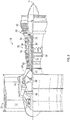
Fig. 2 is a cross-sectional diagram of a gas turbine engine of an aircraft according to one embodiment; -
Fig. 3 is a schematic of a bleed air system for use with an aircraft engine according to one embodiment; -
FIG. 4 is a cross-sectional diagram of an example of a turbo-generator of the bleed air system according to an embodiment; and -
FIG. 5 is a cross-sectional diagram of an example of a boost compressor of the bleed air system according to an embodiment. - A detailed description of one or more embodiments of the disclosed system is presented herein by way of exemplification and not limitation with reference to the Figures. It is to be understood that other embodiments may be utilized and changes may be made without departing from the scope of the present disclosure.
-
FIG. 1 illustrates an example of a commercial aircraft 10 havingaircraft engines 20 that may embody aspects of the teachings of this disclosure. With reference toFIG. 2 , an example of agas turbine engine 20 configured for use in the aircraft 10 is illustrated schematically. Thegas turbine engine 20 disclosed herein is a two-spool turbofan that generally incorporates afan section 22, acompressor section 24, acombustor section 26 and aturbine section 28. Alternative engines might include an augmentor section (not shown) among other systems or features. Thefan section 22 drives air along a bypass flow path while thecompressor section 24 drives air along a core flow path for compression and communication into thecombustor section 26 and then expansion through theturbine section 28. Although depicted as a turbofangas turbine engine 20 in the disclosed non-limiting embodiment, it should be understood that the concepts described herein are not limited to use with turbofans as the teachings may be applied to other types of turbine engines, such as three-spool architectures for example. - The
engine 20 generally includes alow spool 30 and ahigh spool 32 mounted for rotation about an engine central longitudinal axis A relative to an enginestatic structure 36 viaseveral bearing systems 38. It should be understood thatvarious bearing systems 38 at various locations may alternatively or additionally be provided. - The
low spool 30 generally includes aninner shaft 40 that interconnects afan 42, alow pressure compressor 44, and alow pressure turbine 46. Theinner shaft 40 may be connected to thefan 42 directly or through a gearedarchitecture 48 to drive thefan 42 at a different, typically lower, speed than thelow spool 30. Thehigh spool 32 includes anouter shaft 50 that interconnects ahigh pressure compressor 52 and ahigh pressure turbine 54. Acombustor 56 is arranged between thehigh pressure compressor 52 and thehigh pressure turbine 54. Theinner shaft 40 and theouter shaft 50 are concentric and rotate about the engine central longitudinal axis A which is collinear with their longitudinal axes. - The core airflow is compressed by the
low pressure compressor 44 then thehigh pressure compressor 52, mixed and burned with fuel in thecombustor 56, then expanded over thehigh pressure turbine 54 andlow pressure turbine 46. Theturbines low spool 30 andhigh spool 32 in response to the expansion. - Referring now to
FIG. 3 , eachengine 20 of the aircraft 10 may employ a dedicatedbleed air system 60, or the plurality ofengines 20 may employ a commonbleed air system 60. Thebleed air system 60 provides compressed or pressurized air to one or more aircraft systems such as, for example, an environmental control system, illustrated schematically at 58, to pressurize the cabin of an aircraft 10. Alternatively, or in addition, the bleed air may be used for anti-icing or deicing, heating or cooling, and/or operating pneumatic equipment, as illustrated schematically at 59. - The
bleed air system 60 includes at least oneport 62 for extracting air at various stages of the engine theengine 20. In the illustrated, non-limiting embodiment, thesystem 60 includes one ormore ports 62 configured to bleed low pressure air from a portion of thelow pressure spool 30, such as thelow pressure compressor 44 for example. The air drawn from theport 62 may have a maximum temperature of about 800°F and a maximum pressure of about 150 psia. However, embodiments where theport 62 is located at another low pressure position, or alternatively, is configured to draw high pressure bleed air are also contemplated herein. - The
bleed air system 60 additionally includes a turbo-generator 64 and aboost compressor 66. A first bleedpassage 68 fluidly couples theport 62 to the turbo-generator 64, and a second bleedpassage 70 fluidly couples theport 62 to the boost-compressor 66. In the illustrated, non-limiting embodiment, the secondbleed passage 70 extends from the firstbleed passage 68 upstream from the turbo-generator 64. Anisolation valve 72 may be disposed within thesecond passage 70 upstream from the inlet 74 of theboost compressor 66. Theisolation valve 72 may be selectively operable to control a flow of bleed air to the boost-compressor 66. It should be understood that thesystem 60 illustrated and described herein is intended as an example only, and embodiments of thebleed system 60 where the firstbleed passage 68 and the secondbleed passage 70 are not arranged in fluid communication are also within the scope of the disclosure. - As previously described, the bleed air output from both the turbo-
generator 64 and the boost-compressor 66 may be provided to any of a number ofaircraft systems outlet passages generator 64 and the boost-compressor 66, respectively, may be fluidly coupled. In such embodiments, a oneway check valve 80 is positioned downstream from the turbo-generator 64, but upstream from the interface between theoutlet passages check valve 80 is configured to prevent the flow of bleed air from the outlet of thecompressor 66 from flowing through theoutlet passages generator 64. - Depending on the demands of the aircraft 10, bleed air from the
port 62 is selectively provided to one of the turbo-generator 64 and theboost compressor 66. For example, when the energy of the bleed air drawn atport 62 is greater than the demands of the one or more of theaircraft systems generator 64. The turbo-generator 64 is configured to reduce the pressure and/or the temperature of the air provided thereto from thebleed port 62. In an embodiment, the turbo-generator 64 is configured to reduce the temperature of the bleed air to less than 450°F and reduce the pressure of the bleed air to less than 50 psia. - An example of a turbo-
generator 64 for use in thebleed air system 60 is illustrated in more detail inFIG. 4 . The turbo-generator 64 includes aturbine 82 that directly drives anelectric generator 84. In the illustrated, non-limiting embodiment, theturbine 82 is mounted on ashaft 86 and theelectric generator 84 includes ashaft 88. Acoupler 90, separate from or integrally formed with one of theshafts turbine shaft 86 and thegenerator shaft 88 such that rotation of theturbine shaft 86 is transmitted to thegenerator shaft 88. Rotation of theturbine 82, driven by the flow of bleed air provided at aninlet opening 92, drives rotation of thegenerator shaft 88. Accordingly, rotation of theturbine 82 extracts energy from the bleed air and converts it into electrical energy via thegenerator 84. The energy created at thegenerator 84 may be stored, or alternatively, may be sent to an aircraft bus (not shown) where it is then supplied to one or more electrical loads of the aircraft 10. - The operational parameters of the turbo-
generator 64 may be varied to achieve a desired reduction in not only pressure, but also temperature of the bleed air. For example, if the temperature of the bleed air requires cooling, the current flow from thegenerator 84 may be increased causing thegenerator 84 to develop more input torque. The increased torque will result in slower rotation of theturbine 82 causing more energy to be extracted from the bleed air before exiting from anoutlet 94 of the turbo-generator 64. - When the pressure of the bleed air drawn from
port 62 is less than the pressure demands of theaircraft systems engines 20 are idling or during descent for example, theisolation valve 72 is opened and the bleed air is provided to theboost compressor 66. - An example of a
boost compressor 66 of thebleed air system 60 is illustrated in more detail inFIG. 5 . Theboost compressor 66 includes acompressor 96 coupled to ahigh temperature motor 98. Theboost compressor 66 is configured to add energy to the bleed air when needed and to increase the pressure and/or temperature of the bleed air. As the bleed air passes from the inlet 74 to the outlet of theboost compressor 66, electrical energy, such as supplied by the aircraft bus for example, is used to operate themotor 98 of theboost compressor 66. The electrical energy is converted into pneumatic energy which is then added to the low pressure bleed air within theboost compressor 66. - The bleed air system illustrated and described herein eliminates the need for bleed air hardware including valves and a pre-cooler, thereby increasing the reliability of the bleed air system. Further, by capturing excess energy of the bleed air, the
bleed air system 60 which further increases the fuel efficiency of the aircraft. - While the invention has been described with reference to one or more embodiments, it will be understood by those skilled in the art that various changes may be made and equivalents may be substituted for elements thereof without departing from the scope of the invention. In addition, many modifications may be made to adapt a particular situation or material to the teachings of the invention without departing from the essential scope thereof. Also, in the drawings and the description, there have been disclosed embodiments of the invention and, although specific terms may have been employed, they are unless otherwise stated used in a generic and descriptive sense only and not for purposes of limitation, the scope of the invention therefore not being so limited. Moreover, the use of the terms first, second, etc. , do not denote any order or importance, but rather the terms first, second, etc. are used to distinguish one element from another. Furthermore, the use of the terms a, an, etc. do not denote a limitation of quantity, but rather denote the presence of at least one of the referenced item.
Claims (15)
- An engine bleed air system (60) for providing air to an aircraft system, comprising:a port (62) for extracting bleed air from a compressor section (24) of an engine (20);a turbo-generator (64) having a turbine (82) and a generator (84), the generator (84) being driven by rotation of the turbine (82); anda boost compressor (66) fluidly coupled to the port (62), wherein the bleed air from the port (62) is selectively provided to one of the turbo-generator (64) and the boost compressor (66) based on a demand of the aircraft system.
- The system of claim 1, wherein the port (62) is configured to draw low pressure air from the engine (20).
- The system of claim 2, wherein the port (62) is configured to bleed air from a low pressure compressor of a low pressure spool (30) of the engine (20).
- The system of claim 1, wherein bleed air is provided to the turbo-generator (64) when an energy of the bleed air is greater than the demand of the aircraft system.
- The system of claim 4, wherein the turbo-generator (64) is configured to reduce at least one of a pressure and temperature of the bleed air.
- The system of claim 4, wherein the turbo-generator (64) extracts energy from the bleed air and converts it into electrical energy via the generator (84).
- The system of claim 6, wherein the electrical energy extracted via the generator (84) is supplied to one or more electrical loads.
- The system of claim 1, wherein bleed air is provided to the boost compressor (66) when an energy of the bleed air is less than the demand of the aircraft system.
- The system of claim 7, wherein the boost compressor (66) is configured to add energy to the bleed air.
- The system of claim 7, wherein the boost compressor (66) is configured to increase at least one of a temperature and pressure of the bleed air.
- The system of any preceding claim, wherein the aircraft system includes one or more of an environmental control system and an anti-icing system.
- The system of any preceding claim, further comprising an isolator valve disposed upstream from the boost compressor, the isolator valve being operable to control a flow of bleed air to the turbo-generator and the boost compressor.
- The system of any preceding claim, further comprising:a first outlet passage (76) extending from the turbo-generator (64);a second outlet passage (78) extending from the boost compressor, the second outlet passage (78) and the first outlet passage (76) being arranged in fluid communication; anda one way check valve (80) disposed downstream from an outlet of the turbo-generator (64) and upstream from an interface between the first outlet passage (76) and the second outlet passage (78).
- A method of operating a bleed air system of an aircraft comprising:determining a demand of one or more aircraft systems;extracting bleed air from an engine via a port (62);providing the bleed air to a turbo-generator (64) if an energy of the bleed air is greater than the demand of the one or more aircraft systems; andproviding the bleed air to a boost compressor (66) if the energy of the bleed air is less than the demand of the one or more aircraft systems.
- The method of claim 14, further comprising operating an isolator valve to selectively control a flow of the bleed air to the turbo-generator (64) and the boost compressor (66).
Applications Claiming Priority (1)
| Application Number | Priority Date | Filing Date | Title |
|---|---|---|---|
| US15/350,987 US10738695B2 (en) | 2016-11-14 | 2016-11-14 | Electrically boosted regenerative bleed air system |
Publications (2)
| Publication Number | Publication Date |
|---|---|
| EP3321491A1 true EP3321491A1 (en) | 2018-05-16 |
| EP3321491B1 EP3321491B1 (en) | 2022-06-08 |
Family
ID=60327142
Family Applications (1)
| Application Number | Title | Priority Date | Filing Date |
|---|---|---|---|
| EP17201611.5A Active EP3321491B1 (en) | 2016-11-14 | 2017-11-14 | Electrically boosted regenerative bleed air system |
Country Status (2)
| Country | Link |
|---|---|
| US (1) | US10738695B2 (en) |
| EP (1) | EP3321491B1 (en) |
Families Citing this family (2)
| Publication number | Priority date | Publication date | Assignee | Title |
|---|---|---|---|---|
| US11788472B2 (en) | 2021-04-14 | 2023-10-17 | Rtx Corporation | Engine bleed generators and aircraft generator systems |
| CN115506893B (en) * | 2022-10-11 | 2025-06-03 | 中国航发沈阳发动机研究所 | A fuel thermal management system for aircraft engines |
Citations (4)
| Publication number | Priority date | Publication date | Assignee | Title |
|---|---|---|---|---|
| US5899085A (en) * | 1997-08-01 | 1999-05-04 | Mcdonnell Douglas Corporation | Integrated air conditioning and power unit |
| EP1283166A2 (en) * | 2001-08-11 | 2003-02-12 | Honeywell Normalair-Garrett (Holdings) Limited | Conditioning of air supply |
| EP2960467A1 (en) * | 2014-06-27 | 2015-12-30 | Frederick M. Schwarz | Simplified engine bleed supply with low pressure environmental control system for aircraft |
| EP3002431A1 (en) * | 2014-09-30 | 2016-04-06 | Hamilton Sundstrand Corporation | Engine bleed air system |
Family Cites Families (17)
| Publication number | Priority date | Publication date | Assignee | Title |
|---|---|---|---|---|
| US4261416A (en) * | 1979-02-23 | 1981-04-14 | The Boeing Company | Multimode cabin air conditioning system |
| US6189324B1 (en) | 1999-10-05 | 2001-02-20 | Samuel B. Williams | Environment control unit for turbine engine |
| AU2002220089A1 (en) | 2000-11-14 | 2002-05-27 | Capstone Turbine Corporation | Method and apparatus for turbogenerator anti-surge control |
| US6545373B1 (en) | 2001-08-24 | 2003-04-08 | Smiths Aerospace, Inc. | System and method for providing ballast loading for a turbo-generator |
| US6796527B1 (en) | 2001-09-20 | 2004-09-28 | Hamilton Sundstrand Corporation | Integrated air turbine driven system for providing aircraft environmental control |
| US7624592B2 (en) * | 2006-05-17 | 2009-12-01 | Northrop Grumman Corporation | Flexible power and thermal architectures using a common machine |
| US8063501B2 (en) | 2009-06-10 | 2011-11-22 | Hamilton Sundstrand Corporation | Gas turbine bleed energy recovery via counter rotating generator |
| US9062604B2 (en) | 2011-01-14 | 2015-06-23 | Hamilton Sundstrand Corporation | Low pressure bleed architecture |
| US20130040545A1 (en) | 2011-08-11 | 2013-02-14 | Hamilton Sundstrand Corporation | Low pressure compressor bleed exit for an aircraft pressurization system |
| US8978351B2 (en) * | 2011-10-21 | 2015-03-17 | United Technologies Corporation | Integrated thermal management system and environmental control system for a gas turbine engine |
| US8967528B2 (en) | 2012-01-24 | 2015-03-03 | The Boeing Company | Bleed air systems for use with aircrafts and related methods |
| US8957539B1 (en) | 2012-10-16 | 2015-02-17 | The Boeing Company | Hybrid turbogenerator and associated method |
| US10563592B2 (en) | 2012-12-14 | 2020-02-18 | United Technologies Corporation | Turbo compressor for bleed air |
| WO2015026431A1 (en) | 2013-08-21 | 2015-02-26 | Hamilton Sundstrand Corporation | Environmental control generator system and apparatus |
| US10144519B2 (en) | 2014-10-24 | 2018-12-04 | United Technologies Corporation | Compressor bleed air supply for an aircraft environmental control system |
| GB201513952D0 (en) * | 2015-08-07 | 2015-09-23 | Rolls Royce Plc | Aircraft pneumatic system |
| US20180134397A1 (en) | 2016-11-14 | 2018-05-17 | Hamilton Sundstrand Corporation | Turbo-generator based bleed air system |
-
2016
- 2016-11-14 US US15/350,987 patent/US10738695B2/en active Active
-
2017
- 2017-11-14 EP EP17201611.5A patent/EP3321491B1/en active Active
Patent Citations (4)
| Publication number | Priority date | Publication date | Assignee | Title |
|---|---|---|---|---|
| US5899085A (en) * | 1997-08-01 | 1999-05-04 | Mcdonnell Douglas Corporation | Integrated air conditioning and power unit |
| EP1283166A2 (en) * | 2001-08-11 | 2003-02-12 | Honeywell Normalair-Garrett (Holdings) Limited | Conditioning of air supply |
| EP2960467A1 (en) * | 2014-06-27 | 2015-12-30 | Frederick M. Schwarz | Simplified engine bleed supply with low pressure environmental control system for aircraft |
| EP3002431A1 (en) * | 2014-09-30 | 2016-04-06 | Hamilton Sundstrand Corporation | Engine bleed air system |
Also Published As
| Publication number | Publication date |
|---|---|
| US10738695B2 (en) | 2020-08-11 |
| US20180135513A1 (en) | 2018-05-17 |
| EP3321491B1 (en) | 2022-06-08 |
Similar Documents
| Publication | Publication Date | Title |
|---|---|---|
| EP3321490B1 (en) | Turbo-generator based bleed air system | |
| US11384690B2 (en) | System and method of reducing post-shutdown engine temperatures | |
| US10914235B2 (en) | Cooled cooling air system for a gas turbine engine | |
| CA2861131C (en) | Method of operating a multi-pack environmental control system | |
| EP2848534B1 (en) | Aircraft environmental control system (ECS) selectively powered by three bleed ports | |
| US20130040545A1 (en) | Low pressure compressor bleed exit for an aircraft pressurization system | |
| US20180162537A1 (en) | Environmental control system air circuit | |
| EP3002431B1 (en) | Engine bleed air system | |
| US20180009536A1 (en) | Bleed flow extraction system for a gas turbine engine | |
| US10830133B2 (en) | Aircraft environmental control system selectively powered by three bleed ports | |
| EP2809910B1 (en) | Gas turbine engine buffer system | |
| EP2904231B1 (en) | Gas turbine engine including bleed system coupled to upstream and downstream locations of compressor and a corresponding method | |
| US10472071B2 (en) | Hybrid compressor bleed air for aircraft use | |
| EP3321491B1 (en) | Electrically boosted regenerative bleed air system | |
| EP3112268B1 (en) | Aircraft environmental control system selectively powered by three bleed ports |
Legal Events
| Date | Code | Title | Description |
|---|---|---|---|
| PUAI | Public reference made under article 153(3) epc to a published international application that has entered the european phase |
Free format text: ORIGINAL CODE: 0009012 |
|
| STAA | Information on the status of an ep patent application or granted ep patent |
Free format text: STATUS: THE APPLICATION HAS BEEN PUBLISHED |
|
| AK | Designated contracting states |
Kind code of ref document: A1 Designated state(s): AL AT BE BG CH CY CZ DE DK EE ES FI FR GB GR HR HU IE IS IT LI LT LU LV MC MK MT NL NO PL PT RO RS SE SI SK SM TR |
|
| AX | Request for extension of the european patent |
Extension state: BA ME |
|
| STAA | Information on the status of an ep patent application or granted ep patent |
Free format text: STATUS: REQUEST FOR EXAMINATION WAS MADE |
|
| 17P | Request for examination filed |
Effective date: 20181115 |
|
| RBV | Designated contracting states (corrected) |
Designated state(s): AL AT BE BG CH CY CZ DE DK EE ES FI FR GB GR HR HU IE IS IT LI LT LU LV MC MK MT NL NO PL PT RO RS SE SI SK SM TR |
|
| STAA | Information on the status of an ep patent application or granted ep patent |
Free format text: STATUS: EXAMINATION IS IN PROGRESS |
|
| 17Q | First examination report despatched |
Effective date: 20200702 |
|
| GRAP | Despatch of communication of intention to grant a patent |
Free format text: ORIGINAL CODE: EPIDOSNIGR1 |
|
| STAA | Information on the status of an ep patent application or granted ep patent |
Free format text: STATUS: GRANT OF PATENT IS INTENDED |
|
| INTG | Intention to grant announced |
Effective date: 20220112 |
|
| RAP3 | Party data changed (applicant data changed or rights of an application transferred) |
Owner name: HAMILTON SUNDSTRAND CORPORATION |
|
| GRAS | Grant fee paid |
Free format text: ORIGINAL CODE: EPIDOSNIGR3 |
|
| GRAA | (expected) grant |
Free format text: ORIGINAL CODE: 0009210 |
|
| STAA | Information on the status of an ep patent application or granted ep patent |
Free format text: STATUS: THE PATENT HAS BEEN GRANTED |
|
| AK | Designated contracting states |
Kind code of ref document: B1 Designated state(s): AL AT BE BG CH CY CZ DE DK EE ES FI FR GB GR HR HU IE IS IT LI LT LU LV MC MK MT NL NO PL PT RO RS SE SI SK SM TR |
|
| REG | Reference to a national code |
Ref country code: AT Ref legal event code: REF Ref document number: 1497068 Country of ref document: AT Kind code of ref document: T Effective date: 20220615 Ref country code: CH Ref legal event code: EP |
|
| REG | Reference to a national code |
Ref country code: DE Ref legal event code: R096 Ref document number: 602017058242 Country of ref document: DE |
|
| REG | Reference to a national code |
Ref country code: IE Ref legal event code: FG4D |
|
| REG | Reference to a national code |
Ref country code: LT Ref legal event code: MG9D |
|
| REG | Reference to a national code |
Ref country code: NL Ref legal event code: MP Effective date: 20220608 |
|
| PG25 | Lapsed in a contracting state [announced via postgrant information from national office to epo] |
Ref country code: SE Free format text: LAPSE BECAUSE OF FAILURE TO SUBMIT A TRANSLATION OF THE DESCRIPTION OR TO PAY THE FEE WITHIN THE PRESCRIBED TIME-LIMIT Effective date: 20220608 Ref country code: NO Free format text: LAPSE BECAUSE OF FAILURE TO SUBMIT A TRANSLATION OF THE DESCRIPTION OR TO PAY THE FEE WITHIN THE PRESCRIBED TIME-LIMIT Effective date: 20220908 Ref country code: LT Free format text: LAPSE BECAUSE OF FAILURE TO SUBMIT A TRANSLATION OF THE DESCRIPTION OR TO PAY THE FEE WITHIN THE PRESCRIBED TIME-LIMIT Effective date: 20220608 Ref country code: HR Free format text: LAPSE BECAUSE OF FAILURE TO SUBMIT A TRANSLATION OF THE DESCRIPTION OR TO PAY THE FEE WITHIN THE PRESCRIBED TIME-LIMIT Effective date: 20220608 Ref country code: GR Free format text: LAPSE BECAUSE OF FAILURE TO SUBMIT A TRANSLATION OF THE DESCRIPTION OR TO PAY THE FEE WITHIN THE PRESCRIBED TIME-LIMIT Effective date: 20220909 Ref country code: FI Free format text: LAPSE BECAUSE OF FAILURE TO SUBMIT A TRANSLATION OF THE DESCRIPTION OR TO PAY THE FEE WITHIN THE PRESCRIBED TIME-LIMIT Effective date: 20220608 Ref country code: ES Free format text: LAPSE BECAUSE OF FAILURE TO SUBMIT A TRANSLATION OF THE DESCRIPTION OR TO PAY THE FEE WITHIN THE PRESCRIBED TIME-LIMIT Effective date: 20220608 Ref country code: BG Free format text: LAPSE BECAUSE OF FAILURE TO SUBMIT A TRANSLATION OF THE DESCRIPTION OR TO PAY THE FEE WITHIN THE PRESCRIBED TIME-LIMIT Effective date: 20220908 |
|
| REG | Reference to a national code |
Ref country code: AT Ref legal event code: MK05 Ref document number: 1497068 Country of ref document: AT Kind code of ref document: T Effective date: 20220608 |
|
| PG25 | Lapsed in a contracting state [announced via postgrant information from national office to epo] |
Ref country code: RS Free format text: LAPSE BECAUSE OF FAILURE TO SUBMIT A TRANSLATION OF THE DESCRIPTION OR TO PAY THE FEE WITHIN THE PRESCRIBED TIME-LIMIT Effective date: 20220608 Ref country code: LV Free format text: LAPSE BECAUSE OF FAILURE TO SUBMIT A TRANSLATION OF THE DESCRIPTION OR TO PAY THE FEE WITHIN THE PRESCRIBED TIME-LIMIT Effective date: 20220608 |
|
| PG25 | Lapsed in a contracting state [announced via postgrant information from national office to epo] |
Ref country code: NL Free format text: LAPSE BECAUSE OF FAILURE TO SUBMIT A TRANSLATION OF THE DESCRIPTION OR TO PAY THE FEE WITHIN THE PRESCRIBED TIME-LIMIT Effective date: 20220608 |
|
| PG25 | Lapsed in a contracting state [announced via postgrant information from national office to epo] |
Ref country code: SM Free format text: LAPSE BECAUSE OF FAILURE TO SUBMIT A TRANSLATION OF THE DESCRIPTION OR TO PAY THE FEE WITHIN THE PRESCRIBED TIME-LIMIT Effective date: 20220608 Ref country code: SK Free format text: LAPSE BECAUSE OF FAILURE TO SUBMIT A TRANSLATION OF THE DESCRIPTION OR TO PAY THE FEE WITHIN THE PRESCRIBED TIME-LIMIT Effective date: 20220608 Ref country code: RO Free format text: LAPSE BECAUSE OF FAILURE TO SUBMIT A TRANSLATION OF THE DESCRIPTION OR TO PAY THE FEE WITHIN THE PRESCRIBED TIME-LIMIT Effective date: 20220608 Ref country code: PT Free format text: LAPSE BECAUSE OF FAILURE TO SUBMIT A TRANSLATION OF THE DESCRIPTION OR TO PAY THE FEE WITHIN THE PRESCRIBED TIME-LIMIT Effective date: 20221010 Ref country code: EE Free format text: LAPSE BECAUSE OF FAILURE TO SUBMIT A TRANSLATION OF THE DESCRIPTION OR TO PAY THE FEE WITHIN THE PRESCRIBED TIME-LIMIT Effective date: 20220608 Ref country code: CZ Free format text: LAPSE BECAUSE OF FAILURE TO SUBMIT A TRANSLATION OF THE DESCRIPTION OR TO PAY THE FEE WITHIN THE PRESCRIBED TIME-LIMIT Effective date: 20220608 Ref country code: AT Free format text: LAPSE BECAUSE OF FAILURE TO SUBMIT A TRANSLATION OF THE DESCRIPTION OR TO PAY THE FEE WITHIN THE PRESCRIBED TIME-LIMIT Effective date: 20220608 |
|
| PG25 | Lapsed in a contracting state [announced via postgrant information from national office to epo] |
Ref country code: PL Free format text: LAPSE BECAUSE OF FAILURE TO SUBMIT A TRANSLATION OF THE DESCRIPTION OR TO PAY THE FEE WITHIN THE PRESCRIBED TIME-LIMIT Effective date: 20220608 Ref country code: IS Free format text: LAPSE BECAUSE OF FAILURE TO SUBMIT A TRANSLATION OF THE DESCRIPTION OR TO PAY THE FEE WITHIN THE PRESCRIBED TIME-LIMIT Effective date: 20221008 |
|
| REG | Reference to a national code |
Ref country code: DE Ref legal event code: R097 Ref document number: 602017058242 Country of ref document: DE |
|
| PG25 | Lapsed in a contracting state [announced via postgrant information from national office to epo] |
Ref country code: AL Free format text: LAPSE BECAUSE OF FAILURE TO SUBMIT A TRANSLATION OF THE DESCRIPTION OR TO PAY THE FEE WITHIN THE PRESCRIBED TIME-LIMIT Effective date: 20220608 |
|
| PLBE | No opposition filed within time limit |
Free format text: ORIGINAL CODE: 0009261 |
|
| STAA | Information on the status of an ep patent application or granted ep patent |
Free format text: STATUS: NO OPPOSITION FILED WITHIN TIME LIMIT |
|
| PG25 | Lapsed in a contracting state [announced via postgrant information from national office to epo] |
Ref country code: DK Free format text: LAPSE BECAUSE OF FAILURE TO SUBMIT A TRANSLATION OF THE DESCRIPTION OR TO PAY THE FEE WITHIN THE PRESCRIBED TIME-LIMIT Effective date: 20220608 |
|
| 26N | No opposition filed |
Effective date: 20230310 |
|
| PG25 | Lapsed in a contracting state [announced via postgrant information from national office to epo] |
Ref country code: SI Free format text: LAPSE BECAUSE OF FAILURE TO SUBMIT A TRANSLATION OF THE DESCRIPTION OR TO PAY THE FEE WITHIN THE PRESCRIBED TIME-LIMIT Effective date: 20220608 |
|
| P01 | Opt-out of the competence of the unified patent court (upc) registered |
Effective date: 20230522 |
|
| PG25 | Lapsed in a contracting state [announced via postgrant information from national office to epo] |
Ref country code: MC Free format text: LAPSE BECAUSE OF FAILURE TO SUBMIT A TRANSLATION OF THE DESCRIPTION OR TO PAY THE FEE WITHIN THE PRESCRIBED TIME-LIMIT Effective date: 20220608 |
|
| REG | Reference to a national code |
Ref country code: CH Ref legal event code: PL |
|
| REG | Reference to a national code |
Ref country code: BE Ref legal event code: MM Effective date: 20221130 |
|
| PG25 | Lapsed in a contracting state [announced via postgrant information from national office to epo] |
Ref country code: LI Free format text: LAPSE BECAUSE OF NON-PAYMENT OF DUE FEES Effective date: 20221130 Ref country code: CH Free format text: LAPSE BECAUSE OF NON-PAYMENT OF DUE FEES Effective date: 20221130 |
|
| PG25 | Lapsed in a contracting state [announced via postgrant information from national office to epo] |
Ref country code: LU Free format text: LAPSE BECAUSE OF NON-PAYMENT OF DUE FEES Effective date: 20221114 |
|
| PG25 | Lapsed in a contracting state [announced via postgrant information from national office to epo] |
Ref country code: IE Free format text: LAPSE BECAUSE OF NON-PAYMENT OF DUE FEES Effective date: 20221114 |
|
| PG25 | Lapsed in a contracting state [announced via postgrant information from national office to epo] |
Ref country code: BE Free format text: LAPSE BECAUSE OF NON-PAYMENT OF DUE FEES Effective date: 20221130 |
|
| PG25 | Lapsed in a contracting state [announced via postgrant information from national office to epo] |
Ref country code: IT Free format text: LAPSE BECAUSE OF FAILURE TO SUBMIT A TRANSLATION OF THE DESCRIPTION OR TO PAY THE FEE WITHIN THE PRESCRIBED TIME-LIMIT Effective date: 20220608 |
|
| PG25 | Lapsed in a contracting state [announced via postgrant information from national office to epo] |
Ref country code: HU Free format text: LAPSE BECAUSE OF FAILURE TO SUBMIT A TRANSLATION OF THE DESCRIPTION OR TO PAY THE FEE WITHIN THE PRESCRIBED TIME-LIMIT; INVALID AB INITIO Effective date: 20171114 |
|
| PG25 | Lapsed in a contracting state [announced via postgrant information from national office to epo] |
Ref country code: CY Free format text: LAPSE BECAUSE OF FAILURE TO SUBMIT A TRANSLATION OF THE DESCRIPTION OR TO PAY THE FEE WITHIN THE PRESCRIBED TIME-LIMIT Effective date: 20220608 |
|
| PG25 | Lapsed in a contracting state [announced via postgrant information from national office to epo] |
Ref country code: MK Free format text: LAPSE BECAUSE OF FAILURE TO SUBMIT A TRANSLATION OF THE DESCRIPTION OR TO PAY THE FEE WITHIN THE PRESCRIBED TIME-LIMIT Effective date: 20220608 |
|
| PG25 | Lapsed in a contracting state [announced via postgrant information from national office to epo] |
Ref country code: TR Free format text: LAPSE BECAUSE OF FAILURE TO SUBMIT A TRANSLATION OF THE DESCRIPTION OR TO PAY THE FEE WITHIN THE PRESCRIBED TIME-LIMIT Effective date: 20220608 |
|
| PG25 | Lapsed in a contracting state [announced via postgrant information from national office to epo] |
Ref country code: MT Free format text: LAPSE BECAUSE OF FAILURE TO SUBMIT A TRANSLATION OF THE DESCRIPTION OR TO PAY THE FEE WITHIN THE PRESCRIBED TIME-LIMIT Effective date: 20220608 |
|
| PG25 | Lapsed in a contracting state [announced via postgrant information from national office to epo] |
Ref country code: BG Free format text: LAPSE BECAUSE OF FAILURE TO SUBMIT A TRANSLATION OF THE DESCRIPTION OR TO PAY THE FEE WITHIN THE PRESCRIBED TIME-LIMIT Effective date: 20220608 |
|
| PG25 | Lapsed in a contracting state [announced via postgrant information from national office to epo] |
Ref country code: BG Free format text: LAPSE BECAUSE OF FAILURE TO SUBMIT A TRANSLATION OF THE DESCRIPTION OR TO PAY THE FEE WITHIN THE PRESCRIBED TIME-LIMIT Effective date: 20220608 |
|
| PGFP | Annual fee paid to national office [announced via postgrant information from national office to epo] |
Ref country code: DE Payment date: 20251022 Year of fee payment: 9 |
|
| PGFP | Annual fee paid to national office [announced via postgrant information from national office to epo] |
Ref country code: GB Payment date: 20251023 Year of fee payment: 9 |
|
| PGFP | Annual fee paid to national office [announced via postgrant information from national office to epo] |
Ref country code: FR Payment date: 20251022 Year of fee payment: 9 |